GS-5424PLC Switch User Manual
|
|
|
- Jason Gilmore
- 5 years ago
- Views:
Transcription


1 GS-5424PLC Switch User Manual / v1.0
2 CONTENTS I Introduction I-1 Overview I-2 Package Content I-3 Features I-4 Product Components I-4-1 Ports I-4-2 LED Indicators II Installation II-1 Mounting the Switch II-1-1 Placement Tips II-1-2 Rack Mounting III Getting Started III-1 Power III-1-1 Connecting to Power III-1-2 Connecting to Network III-1-3 Power over Ethernet (PoE) Considerations III-1-4 Starting the Web-based Configuration Utility III-1-5 Logging In III-1-6 Logging Out IV Web-based Switch Configuration IV-1 Status IV-1-1 System Information IV-1-2 Logging Message IV-1-3 Port IV Statistics IV Error Disabled IV Bandwidth Utilization IV-1-4 Link Aggregation IV-1-5 MAC Address Table IV-2 Network IV-2-1 IP Address IV-2-2 System Time IV-3 Port IV-3-1 Port Setting... 45
3 IV-3-2 Long Range Mode IV-3-3 Error Disable IV-3-4 Link Aggregation IV Group IV Port Setting IV LACP IV EEE IV-3-5 Jumbo Frame IV-4 PoE IV-4-1 Global Setting IV-4-2 Priority Setting IV-4-3 Power Limit IV-4-4 PoE Status IV-5 VLAN IV-5-1 VLAN IV Create VLAN IV VLAN Configuration IV Membership IV Port Setting IV-5-2 Voice VLAN IV Property IV Voice OUI IV-5-3 MAC VLAN IV MAC Group IV Group Binding IV-6 MAC Address Table IV-6-1 Dynamic Address IV-6-2 Static Address IV-6-3 Filtering Address IV-7 Spanning Tree IV-7-1 Property IV-7-2 Port Setting IV-7-3 MST Instance IV-7-4 MST Port Setting IV-7-5 Statistics IV-8 Discovery IV-8-1 LLDP IV Property IV Port Setting IV Packet View IV Local Information... 97
4 IV Neighbor IV Statistics IV-9 Multicast IV-9-1 General IV Property IV Group Address IV Router Port IV-9-2 IGMP Snooping IV Property IV Querier IV Statistics IV-9-3 MVR IV Property IV Port Setting IV Group Address IV-10 Security IV-10-1 RADIUS IV-10-2 Management Access IV Management Service IV Management ACL IV Management ACE IV-10-3 Authentication Manager IV Property IV Port Setting IV Sessions IV-10-4 Port Security IV-10-5 Protected Port IV-10-6 Storm Control IV-10-7 DoS IV Property IV Port Setting IV-10-8 DHCP Snooping IV Property IV Statistics IV Option82 Property IV Option82 Circuit ID IV-10-9 IP Source Guard IV Port Setting IV IMPV Binding IV Save Database IV-11 ACL
5 IV-11-1 MAC ACL IV-11-2 MAC ACE IV-11-3 IPv4 ACL IV-11-4 IPv4 ACE IV-11-5 ACL Binding IV-12 QoS IV-12-1 General IV Property IV Queue Scheduling IV CoS Mapping IV IP Precedence Mapping IV-12-2 Rate Limit IV Ingress/Egress Port IV-13 Diagnostics IV-13-1 Logging IV Property IV Remote Server IV-13-2 Mirroring IV-13-3 Ping IV-13-4 Traceroute IV-13-5 Copper Test IV-13-6 Fiber Module IV-13-7 UDLD IV Property IV Neighbor IV-14 Management IV-14-1 User Account IV-14-2 Fireware IV Upgrade / Backup IV Active Image IV-14-3 Configuration IV Upgrade / Backup IV Save Configuration IV-14-4 SNMP IV View IV Group IV Community IV User IV Engine ID IV Trap Event IV Notification
6 Safety and Regulatory Audience This guide is for the networking professional managing the standalone PG28CB switch series. It is recommended that only professionals with experience working with Intelligent Technology INC. networking devices who are familiar with the Ethernet and local area networking terminology, should service the equipment. Conventions The following conventions are used in this manual to convey instructions and information: Command descriptions use these conventions: Commands and keywords are in boldface text. Arguments for which you supply values are in italic. Square brackets ([ ]) mean optional elements. Braces ({ }) group required choices, and vertical bars ( ) separate the alternative elements. Braces and vertical bars within square brackets ([{ }]) mean a required choice within an optional element. Interactive examples use these conventions: Nonprinting characters, such as passwords or tabs, are in angle brackets (< >). Notes and cautions use the following conventions and symbols: Note Means additional information. Notes contain additional useful information or references to material available outside of this document. Caution Indicates that the reader must be careful. In a situation where a Caution is listed, a user may cause equipment damage or loss of data. 16


7 I Introduction Thank you for choosing a Edimax (PoE) WEB Smart Ethernet Switch. This device is designed to be operational right out-of-the-box as a standard bridge. In the default configuration, it will forward packets between connecting devices after powered up. Before you begin installing the switch, make sure you have all of the package contents available, and a PC with a web browser for using web-based system management tools. I-1 Overview The Edimax GS-5424PLC is 24-Port Gigabit PoE+ Smart Managed Switch with 4 RJ45/SFP Combo respectively. I-2 Package Content Before using the product, check that the items listed below are included and in good condition. If any item does not accord with the table, please contact your dealer immediately GS-5424PLC Swich 2. Quick Installation Guide 3. CD Power Cord 5. Rack-Mount Kit & Screws 17
8 I-3 Features Supports up to 24 10/100/1000Mbps Gigabit Ethernet ports and 4 SFP slots or 4 mini-gbic/sfp slots IEEE 802.3af/at PoE compliant to simplify deployment and installation Supports PoE up to 30W per port with 400W total power budget Automatically detects powered devices (PD) and power consumption levels IEEE 802.1Q VLAN allows network segmentation to enhance performance and security Supports Access Control List (ACL) Switch capacity: PG28CB: 56Gbps, Forwarding rate: 41.6Mbps Supports IGMP Snooping V1 / V2 / V3 8K MAC address table and 10K jumbo frames 19-inch rack-mountable metal case I-4 Product Components I-4-1 Ports The following view applies to GS-5424PLC. 1 2 Figure 1 - Front View No. Name 1 10/100/1000Mbps RJ-45 ports (1-24) 2 RJ45/SFP combo Ports (SFP1, SFP2, SFP3, and SFP4) Designed to connect to network devices with a bandwidth of 10Mbps, 100Mbps or 1000Mbps. Each has a corresponding 10/100/1000Mbps LED. Designed to install SFP modules or RJ-45 connect to network devices with a bandwidth of 1000Mbps. Each has a corresponding 1000Mbps LED. 18
9 The following view applies to GS-5424PLC. 1 Figure 2 - Rear View No. Name 1 AC power in Support AC V 50-60Hz. I-4-2 LED Indicators The following view applies to GS-5424PLC Figure 3 - Front View LED Indicators No. Name 1 Power 2 System 3 Port LED 4 SFP LED Off: power off On: power on Off: system not ready On: system ready Blinking: system boot-up LINK/ACT bi-color LED: Off: port disconnected or link fail Green on: 1000Mbs connected, PoE power output on Amber on: 10/100Mbs connected Blinking: sending or receiving data Off: port disconnected or link fail Green on: 1000Mbs connected 19

10 II Installation This chapter describes how to install and connect your Edimax Switch. Read the following topics and perform the procedures in the correct order. Incorrect installation may cause damage to the product. II-1 Mounting the Switch There are two ways to physically set up the switch. Place the switch on a flat surface. To place the switch on a desktop, install the four rubber feet (included) on the bottom of the switch. Mount the switch in a standard rack (1 rack unit high). II-1-1 Placement Tips Ambient Temperature To prevent the switch from overheating, do not operate it in an area that exceeds an ambient temperature of 122 F (50 C). Air Flow Be sure that there is adequate air flow around the switch. Mechanical Loading Be sure that the switch is level and stable to avoid any hazardous conditions. Circuit Overloading Adding the switch to the power outlet must not overload that circuit. Follow these guidelines to install the switch securely. Put the switch in a stable place such as a desktop, to avoid it falling. Ensure the switch works in the proper AC input range and matches the voltage labeled. Ensure there is proper heat dissipation from and adequate ventilation around the switch. Ensure the switch s location can support the weight of the switch and its accessories. Figure 4 - Desktop Installation 20

11 II-1-2 Rack Mounting You can mount the switch in any standard size, 19-inch (about 48 cm) wide rack. The switch requires 1 rack unit (RU) of space, which is 1.75 inches (44.45 mm) high. For stability, load the rack from the bottom to the top, with the heaviest devices on the bottom. A top-heavy rack is likely to be unstable and may tip over. When mounting smaller switch products into a standard 19-inch rack, a pair of extension brackets (sometimes referred to as ears) are needed to adapt the switch to the rack size. These extension brackets are mounted on the switch using the screws provided in the kit, and have two holes that are used to then screw the switch into the rack. An example of one type of these extension brackets is shown in the following figure. A common problem that occurs during rack mounting is the distance between the screw holes on the rack. Some racks are made with a uniform distance between all of the holes, and others have the holes organized into groups (see photo on the next page for an example). When organized into groups, the switch must be placed in the rack so that the holes in the extension brackets line up correctly. 1. Align the mounting brackets with the mounting holes on the switch s side panels and secure the brackets with the screws provided. Figure 5 - Bracket Installation 21

12 2. Secure the switch on the equipment rack with the screws provided. Figure 6 - Rack Installation 22
13 III Getting Started This section provides an introduction to the web-based configuration utility, and covers the following topics: Powering on the device Connecting to the network Power over Ethernet (PoE) considerations Starting the web-based configuration utility III-1 III-1-1 Power Connecting to Power Power down and disconnect the power cord before servicing or wiring a switch. Do not disconnect modules or cabling unless the power is first switched off. The device only supports the voltage outlined in the type plate. Do not use any other power components except those specifically designated for the switch. Disconnect the power cord before installation or cable wiring. The switch is powered by the AC V 50/60Hz internal high-performance power supply. It is recommended to connect the switch with a single-phase three-wire power source with a neutral outlet, or a multifunctional computer professional source. Connect the AC power connector on the back panel of the switch to the external power source with the included power cord, and check the power LED is on. Figure 7 - Rear View AC Power Socket 23

14 III-1-2 Connecting to Network To connect the switch to the network: 1. Connect an Ethernet cable to the Ethernet port of a computer 2. Connect the other end of the Ethernet cable to one of the numbered Ethernet ports of the switch. The LED of the port lights if the device connected is active. 3. Repeat Step 1 and Step 2 for each device to connect to the switch. We strongly recommend using CAT-5E or better cable to connect network devices. When connecting network devices, do not exceed the maximum cabling distance of 100 meters (328 feet). It can take up to one minute for attached devices or the LAN to be operational after it is connected. This is normal behavior. Connect the switch to end nodes using a standard Cat 5/5e Ethernet cable (UTP/STP) to connect the switch to end nodes as shown in the illustration below. Switch ports will automatically adjust to the characteristics (MDI/MDI-X, speed, duplex) of the device to which the switch is connected. Figure 8 - PC Connect 24
15 III-1-3 Power over Ethernet (PoE) Considerations For PoE switch models, consider the following information: Devices considered a Power Sourcing Equipment (PSE), can support up to 30 Watts per PoE port to a Powered Device (PD). Model Power Dedicated to PoE PoE Ports PoE Standard Supported GS-542PLC 400W 1 to 24 IEEE802.3at/af Ports 1-24 provide PoE power supply functionality with a maximum output power up to 30W each port. This can supply power to PDs such as internet phones, network cameras, wireless access points. Connect the switch PoE port directly to the PD port using a network cable. When connecting switches capable of supplying PoE, consider the following information: Switch models with PoE function are PSEs. These models are capable of supplying DC power to attached PDs, such as VoIP phones, IP cameras, and wireless access points (APs). PoE switches. Additionally, PoE switches are capable of detecting and supplying power to pre-standard legacy PoE Power Devices. Due to the support for legacy PoE, there is a possibility that PoE switches acting as a PSE may inadvertently detect and supply power an attached PSE, including other PoE switches. This false detection may result in a PoE switch operating improperly and unable to supply power to attached PDs. The prevention of a false detection can be easily remedied by disabling PoE on the ports that are used to connect PSEs. Another simple practice to prevent a false detection is to first power up a PSE device before connecting it to a PoE switch. When a device is falsely detected as a PD, disconnect the device from the PoE port and power recycle the device with AC power before reconnecting it to the PoE port. 25

16 III-1-4 Starting the Web-based Configuration Utility This section describes how to navigate the web-based switch configuration utility. Be sure to disable any pop-up blocker. Browser Restrictions If you are using older versions of Internet Explorer, you cannot directly use an IPv6 address to access the device. You can, however, use the DNS (Domain Name System) server to create a domain name that contains the IPv6 address, and then use that domain name in the address bar in place of the IPv6 address. If you have multiple IPv6 interfaces on your management station, use the IPv6 global address instead of the IPv6 link local address to access the device from your browser. Launching the Configuration Utility To open the web-based configuration utility: 1. Open a Web browser. 2. Enter the IP address of the device you are configuring in the address bar on the browser (factory default IP address is ) and then press Enter. When the device is using the factory default IP address, its power LED flashes continuously. When the device is using a DHCP assigned IP address or an administrator-configured static IP address, the power LED is lit a solid color. Your computer s IP address must be in the same subnet as the switch. For example, if the switch is using the factory default IP address, your computer s IP address can be in the following range: x (whereas x is a number from 2 to 254). After a successful connection, the login window displays. Figure 9 - Login Window 26
17 III-1-5 Logging In The default username is admin and the default password is admin. The first time that you log in with the default username and password, you are required to enter a new password. To log in to the device configuration utility: 1. Enter the default user ID (admin) and the default password (admin). 2. If this is the first time that you logged on with the default user ID (admin) and the default password (admin) it is recommended that you change your password immediately. See Administrator for additional information. When the login attempt is successful, the System Information window displays. Figure 10 - System Information If you entered an incorrect username or password, an error message appears and the Login page remains displayed on the window. If you are having problems logging in, 27
18 please see the Launching the Configuration Utility section in the Administration Guide for additional information. III-1-6 Logging Out By default, the application logs out after ten minutes of inactivity. To manually logout, click Logout in the top right corner of any page. When a timeout occurs or you intentionally log out of the system, a message appears and the Login page appears, with a message indicating the logged-out state. After you log in, the application returns to the initial page. 28
19 IV Web-based Switch Configuration The PoE smart switch software provides rich Layer 2 functionality for switches in your networks. This chapter describes how to use the web-based management interface (Web UI) to configure the switch s features. For the purposes of this manual, the user interface is separated into four sections, as shown in the following figure: Figure 11 - User Interface No. Name 1 Configuration menu Navigate to locate specific switch functions. 2 Configuration settings Edit specific function settings. Switch s current link Green squares indicate the port link is up, while black squares 3 status indicate the port link is down. 4 Common toolbar Provides access to frequently used settings. 29

20 IV-1 Status Use the Status pages to view system information and status. IV-1-1 System Information This page shows switch panel, CPU utilization, Memory utilization and other system current information. It also allows user to edit some system information. To display the Device Information web page, click Status > System Information. Figure 12 - Status > System Information Model System Name System Location System Contact MAC Address IPv4 Address Model name of the switch. System name of the switch. This name will also use as CLI prefix of each line. ( Switch> or Switch# ). Location information of the switch. Contact information of the switch. Base MAC address of the switch. Current system IPv4 address. 30

21 System OID System Uptime Current Time Loader Version Loader Date Firmware Version Firmware Date Telnet SSH HTTP HTTPS SNMP SNMP system object ID. Total elapsed time from booting. Current system time. Boot loader image version. Boot loader image build date. Current running firmware image version. Current running firmware image build date. Current Telnet service enable/disable state. Current SSH service enable/disable state. Current HTTP service enable/disable state. Current HTTPS service enable/disable state. Current SNMP service enable/disable state. Click Edit button on the table title to edit following system information. Figure 13 - Status > System Information > Edit System Information System Name System Location System Contact System name of the switch. This name will also use as CLI prefix of each line. ( Switch> or Switch# ). Location information of the switch. Contact information of the switch. 31

22 IV-1-2 Logging Message To view the logging messages stored on the RAM and Flash, click Status > Logging Message. Figure 14 - Status > Logging Message Log ID Time Severity Viewing Clear Refresh The log identifier. The time stamp for the logging message. The severity for the logging message. The description of logging message. RAM: Show the logging messages stored on the RAM. Flash: Show the logging messages stored on the Flash. Clear the logging messages. Refresh the logging messages. 32
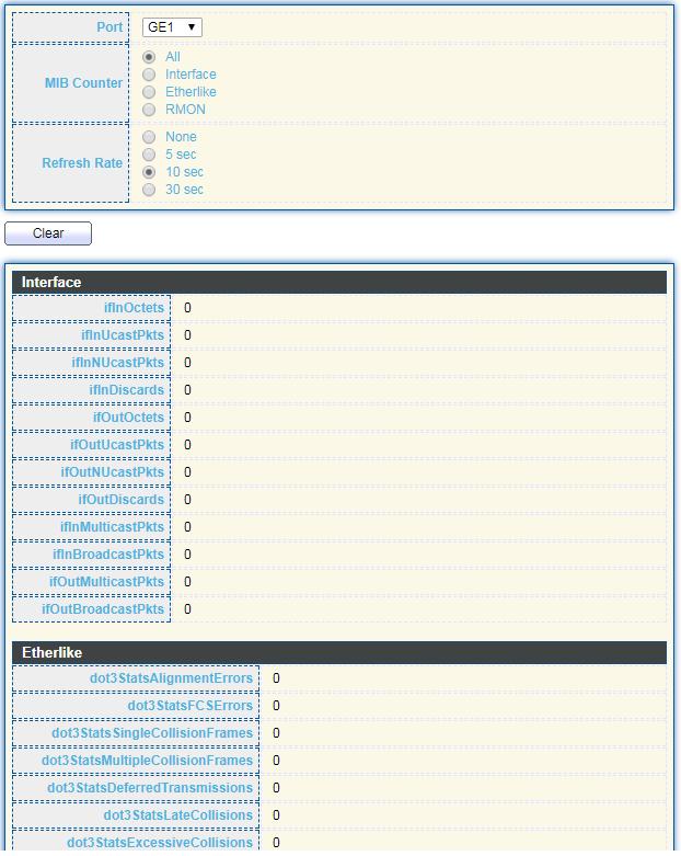
23 IV-1-3 IV Port Statistics This page displays standard counters on network traffic form the Interfaces, Ethernet -like and RMONMIB. Interfaces and Ethernet-like counters display errors on the traffic passing through each port. RMON counters provide a total count of different frame types and sizes passing through each port. The Clear button will clear MIB counter of current selected port. To display the Port Flow Chart web page, click Status > Port > Statistics. 33
24 34

25 Figure 15 - Status > Port > Statistics Port MIB Counter Refresh Rate Select one port to show counter statistics. Select the MIB counter to show different counter type All: All counters. Interface: Interface related MIB counters. Etherlike: Ethernet-like related MIB counters. RMON: RMON related MIB counters. Refresh the web page every period of seconds to get new counter of specified port. 35

26 IV Error Disabled To display the Error Disabled web page, click Status > Port > Error Disabled. Figure 16 - Status > Port > Error Disabled Port Reason Select one or more port to operate. Interface or port number. Port will be disabled by one of the following error reason: BPDU Guard UDLD Self Loop Broadcast Flood Unknown Multicast Flood Unicast Flood ACL 36

27 Time Left (sec) Refresh Recover Port Security Violation DHCP rate limit ARP rate limit The time left in second for the error recovery. Refresh the current page. Recover the selected port status. IV Bandwidth Utilization This page allow user to browse ports bandwidth utilization in real time. This page will refresh automatically in every refresh period. To display Bandwidth Utilization web page, click Status > Port > Bandwidth Utilization. Figure 17 - Status > Port > Bandwidth Utilization Refresh Rate Refresh the web page every period of seconds to get new bandwidth utilization data. 37

28 IV-1-4 Link Aggregation To display the Link Aggregation web page, click Status > Link Aggregation. Figure 18 - Status > Link Aggregation LAG Name Type Link Status Active Member Inactive Member LAG Name. LAG port description. The type of the LAG. Static: The group of ports assigned to a static LAG are always active members. LACP: The group of ports assigned to dynamic LAG are candidate ports. LACP determines which candidate ports are active member ports. LAG port link status. Active member ports of the LAG. Inactive member ports of the LAG. 38

29 IV-1-5 MAC Address Table The MAC address table page displays all MAC address entries on the switch including static MAC address created by administrator or auto learned from hardware. The Clear button will clear all dynamic entries and Refresh button will retrieve latest MAC address entries and show them on page. To display the MAC Address Table web page, click Status > MAC Address Table. Figure 19 - Status > MAC Address Table VLAN MAC Address Type Port VLAN ID of the mac address. MAC address. The type of MAC address Management: DUT s base mac address for management Purpose. Static: Manually configured by administrator Dynamic: Auto learned by hardware. The type of Port CPU: DUT s CPU port for management purpose. Other: Normal switch port. 39
30 IV-2 Network Use the Network pages to configure settings for the switch network interface and how the switch connects to a remote server to get services. IV-2-1 IP Address This section allows you to edit the IP address, Netmask, Gateway and DNS server of the switch. To view the IP Address menu, navigate to Network > IP Address. 40

31 Figure 20 - Network > IP Address Address Type IP Address Subnet Mask Default Gateway The address type of switch IP configuration including Static: Static IP configured by users will be used. Dynamic: Enable the DHCP to obtain the IP address from a DHCP server. Specify the switch static IP address on the static configuration. Specify the switch subnet mask on the static configuration. Specify the default gateway on the static configuration. The 41
32 default gateway must be in the same subnet with switch IP address configuration. DNS Server 1 Specify the primary user-defined IPv4 DNS server configuration. DNS Server 2 Specify the secondary user-defined IPv4 DNS server configuration. Table 3-2: IPv6 Address fields IPv4 Address The operational IPv4 address of the switch. IPv4 Gateway The operational IPv4 gateway of the switch. IPv6 Address v6 The operational IPv6 address of the switch. IPv6 Gateway The operational IPv6 gateway of the switch. Link Local Address The IPv6 link local address for the switch. 42

33 IV-2-2 System Time This page allow user to set time source, static time, time zone and daylight saving settings. Time zone and daylight saving takes effect both static time or time from SNTP server. To display System Time page, click Network > System Time. Figure 21 - Network > System Time Source Select the time source. 43
34 Time Zone SNTP Address Type Server Address Server Port Manual Time Date Time Daylight Saving Time Type Offset Recurring From Recurring To Non-recurring From Non-recurring To Non-recurring From Non recurring To SNTP: Time sync from NTP server. From Computer: Time set from browser host. Manual Time: Time set by manually configure. Select a time zone difference from listing district. Select the address type of NTP server. This is enabled when time source is SNTP. Input IPv4 address or hostname for NTP server. This is enabled when time source is SNTP. Input NTP port for NTP server. Default is 123. This is enabled when time source is SNTP. Input manual date. This is enabled when time source is manual. Input manual time. This is enabled when time source is manual. Select the mode of daylight saving time. Disable: Disable daylight saving time. Recurring: Using recurring mode of daylight saving time. Non-Recurring: Using non-recurring mode of daylight saving time. USA: Using daylight saving time in the United States that starts on the second Sunday of March and ends on the first Sunday of November. European: Using daylight saving time in the Europe that starts on the last Sunday in March and ending on the last Sunday in October. Specify the adjust offset of daylight saving time. Specify the starting time of recurring daylight saving time. This field available when selecting Recurring mode. Specify the ending time of recurring daylight saving time. This field available when selecting Recurring mode. Specify the starting time of non-recurring daylight saving time. This field available when selecting Non-Recurring mode. Specify the ending time of recurring daylight saving time. This field available when selecting Non-Recurring mode. Specify the starting time of non-recurring daylight saving time. This field available when selecting Non-Recurring mode. Specify the ending time of recurring daylight saving time. This field available when selecting Non-Recurring mode. 44

35 IV-3 Port Use the Port pages to configure settings for switch port related features. IV-3-1 Port Setting This page shows port current status and allow user to edit port configura-tions. Select port entry and click Edit button to edit port configurations. To display Port Setting web page, click Port > Port Setting. Figure 22 - Port > Port Setting Port Type Port Name. Port media type. Port. 45

36 State Link Status Speed Duplex Flow Control Port admin state Enabled: Enable the port. Disabled: Disable the port. Current port link status Up: Port is link up. Down: Port is link down. Current port speed configuration and link speed status. Current port duplex configuration and link duplex status. Current port flow control configuration and link flow control status. Click Edit button to edit Port Setting menu Figure 23 - Port > Port Setting > Port Setting Port State Speed Selected Port list. Port media type. Port admin state. Enabled: Enable the port. Disabled: Disable the port. Port speed capabilities. Auto: Auto speed with all capabilities. Auto-10M: Auto speed with 10M ability only. 46
37 Duplex Flow Control Auto-100M: Auto speed with 100M ability only. Auto-1000M: Auto speed with 1000M ability only. Auto-10M/100M: Auto speed with 10M/100M abilities. 10M: Force speed with 10M ability. 100M: Force speed with 100M ability. 1000M: Force speed with 1000M ability. Port duplex capabilities. Auto: Auto duplex with all capabilities. Half: Auto speed with 10M and 100M ability only. Full: Auto speed with 10M/100M/1000M ability only. Port flow control. Auto: Auto flow control by negotiation. Enabled: Enable flow control ability. Disabled: Disable flow control ability. 47

38 IV-3-2 Long Range Mode This page shows port current status and Enable long range mode will double the cabling distance but reduce the speed to 10Mbps. To display Long Range Mode web page, click Port > Long Range Mode Setting. Figure 24 - Port > Long Range Mode 48

39 IV-3-3 Error Disable To display Error Disabled web page, click Port > Error Disabled Recover Interval BPDU Guard UDLD Self Loop Broadcast Flood Unknown Multicast Flood Unicast Flood ACL Port Security DHCP rate limit Figure 25 - Port > Error disable Auto recovery after this interval for error disabled port. Enabled to auto shutdown port when BPDU Guard reason occur. This reason caused by STP BPDU Guard mechanism. Enabled to auto shutdown port when UDLD violation occur. Enabled to auto shutdown port when Self Loop reason occur. Enabled to auto shutdown port when Broadcast Flood reason occur. This reason caused by broadcast rate exceed broadcast storm control rate. Enabled to auto shutdown port when Unknown Multicast Flood reason occur. This reason caused by unknown multicast rate exceed unknown multicast storm control rate. Enabled to auto shutdown port when Unicast Flood reason occur. This reason caused by unicast rate exceed unicast storm control rate. Enabled to auto shutdown port when ACL shutdown port reason occur. This reason caused packet match the ACL shutdown port action. Enabled to auto shutdown port when Port Security Violation reason occur. This reason caused by violation port security rules. Enabled to auto shutdown port when DHCP rate limit reason occur. This reason caused by DHCP packet rate exceed DHCP rate limit. 49

40 ARP rate limit Enabled to auto shutdown port when ARP rate limit reason occur. This reason caused by DHCP packet rate exceed ARP rate limit. IV-3-4 IV Link Aggregation Group This page allow user to configure link aggregation group load balance algorithm and group member. To view the Group menu, navigate to Port > Link Aggregation > Group. Figure 26 - Port > Link Aggregation > Group Load Balance Algorithm LAG Name Type Link Status LAG load balance distribution algorithm src-dst-mac: Based on MAC address. src-dst-mac-ip: Based on MAC address and IP address. LAG Name. LAG port description. The type of the LAG Static: The group of ports assigned to a static LAG are always active members. LACP: The group of ports assigned to dynamic LAG are candidate ports. LACP determines which candidate ports are active member ports. LAG port link status 50

41 Active Member Inactive Member Active member ports of the LAG. Inactive member ports of the LAG. Click Edit to edit Link Aggregation Group menu. Figure 27 - Port > Link Aggregation > Group > Edit Link Aggregation Group LAG Name Type Member Selected LAG group ID. LAG port description. The type of the LAG Static: The group of ports assigned to a static LAG are always active members. LACP: The group of ports assigned to dynamic LAG are candidate ports. LACP determines which candidate ports are active member ports. Select available port to be LAG group member port. 51

42 IV Port Setting This page shows LAG port current status and allow user to edit LAG port configurations. Select LAG entry and click Edit button to edit LAG port configurations. To display LAG Port Setting web page, click Port > Link Aggregation > Port Setting. Figure 28 - Port > Link Aggregation > Port Setting LAG Type State Link Status Speed Duplex Flow Control LAG Port Name. LAG Port media type. LAG Port description. LAG Port admin state Enabled: Enable the port. Disabled: Disable the port. Current LAG port link status Up: Port is link up. Down: Port is link down. Current LAG port speed configuration and link speed status. Current LAG port duplex configuration and link duplex status. Current LAG port flow control configuration and link flow control status. 52

43 Click Edit to view Edit Port Setting menu. Figure 29 - Port > Link Aggregation > Port Setting > Edit Port Setting Port State Speed Flow Control Selected Port list. Port description. Port admin state Enabled: Enable the port. Disabled: Disable the port. Port speed capabilities Auto: Auto speed with all capabilities. Auto-10M: Auto speed with 10M ability only. Auto-100M: Auto speed with 100M ability only. Auto-1000M: Auto speed with 1000M ability only. Auto-10M/100M: Auto speed with 10M/100M abilities. 10M: Force speed with 10M ability. 100M: Force speed with 100M ability. 1000M: Force speed with 1000M ability. Port flow control Auto: Auto flow control by negotiation. Enabled: Enable flow control ability. Disabled: Disable flow control ability. 53

44 IV LACP This page allow user to configure LACP global and port configurations. Select ports and click Edit button to edit port configuration. To display the LACP Setting web page, click Port > Link Aggregation > LACP. Figure 30 - Port > Link Aggregation > LACP System Priority Port Port Priority Timeout Configure the system priority of LACP. This decides the system priority field in LACP PDU. Port Name. LACP priority value of the port. The periodic transmissions type of LACP PDUs. Long: Transmit LACP PDU with slow periodic (30s). Short: Transmit LACPP DU with fast periodic (1s). 54
.")
45 Click "Edit" button to view Edit LACP Port Setting menu. Figure 31 - Port > Link Aggregation > LACP > Edit LACP Port Setting Port Port Priority Timeout Selected port list. Enter the LACP priority value of the port The periodic transmissions type of LACP PDUs. Long: Transmit LACP PDU with slow periodic (30s). Short: Transmit LACPP DU with fast periodic (1s). 55

46 IV EEE This page allow user to configure Energy Efficient Ethernet settings. To display the EEE web page, click Port > EEE. Figure 32 - Port > EEE Port State Operational Status Port Name. Port EEE admin state Enabled: EEE is enabled. Disabled: EEE is disabled. Port EEE operational status Enabled: EEE is operating. Disabled: EEE is no operating. 56

47 Click Edit to edit the EEE menu. Figure 33 - Port > EEE > Edit EEE Setting Port State Port Name Port EEE admin state Enabled: EEE is enabled. Disabled: EEE is disabled. IV-3-5 Jumbo Frame This page allow user to configure switch jumbo frame size. To display Jumbo Frame web page, click Port > Jumbo Frame. Figure 34 - Port > Jumbo Frame Jumbo Frame Enable or disable jumbo frame. When jumbo frame is enabled, switch max frame size is allowed to configure. When jumbo frame is disabled, default frame size 1522 will be used. 57

48 IV-4 PoE Port security can set port isolation and specific behavior. IV-4-1 Global Setting To display the Global web page, click PoE > Global Setting. Figure 35 - PoE > Global Setting 58

49 Nominal Power Consuming Power Remaining Power Schedule Status Name Port List Schedule Status Maximum supply power. Current consumed power. Remaining available power. Schedule status global switch. PoE Schedule Name. The ports provide power in designated schedule index. The current schedule status. Click Edit to view PoE Schedule List menu. Figure 36 - PoE > Priority Setting > Edit PoE Schedule Edit Index Schedule Status Name Date Port List The serial number of schedule list. Schedule Status Checked: Schedule status is enabled. Unchecked: Schedule status is disabled. Enter the PoE schedule name. Select a valid time for this schedule. Select the port provide power. 59

50 IV-4-2 Priority Setting Use this section to set the power supply priority of PoE ports. Individual ports can be assigned critical, high, or low power supply priority. To display the Priority Setting web page, click PoE > Priority Setting. Figure 37 - PoE > Priority Setting Click the port to change its priority status according to the bottom right hand chart. 60

51 IV-4-3 Power Limit To display the Power Limit web page, click PoE > Power Limit. Figure 38 - PoE > Power Limit Port Power Limit Port name. The max supply power for this port. 61

52 Click Edit to view Power Limit Setting menu. Figure 39 - PoE > Power Setting > Power Limit Setting Table Port List Power Limit Selected port list. Enter max supply power value for the selected port list. 62

53 IV-4-4 PoE Status To display the PoE Status web page, click PoE > Power Status. Per Port PoE Status Checked: Port PoE status is enabled. Unchecked: Port PoE status is disabled. Figure 40 - PoE > Power Stauts 63

54 IV-5 VLAN A virtual local area network, virtual LAN or VLAN, is a group of hosts with a common set of requirements that communicate as if they were attached to the same broadcast domain, regardless of their physical location. A VLAN has the same attributes as a physical local area network (LAN), but it allows for end stations to be grouped togeth-er even if they are not located on the same network switch. VLAN membership can be configured through software instead of physically relocating devices or connections. IV-5-1 VLAN Use the VLAN pages to configure settings of VLAN. IV Create VLAN This page allows user to add or delete VLAN ID entries and browser all VLAN entries that add statically or dynamic learned by GVRP. Each VLAN entry has a unique name, user can edit VLAN name in edit page. To display Create VLAN page, click VLAN > VLAN > Create VLAN. Figure 41 - VLAN > VLAN > Create VLAN Available VLAN VLAN has not created yet. Select available VLANs from left box then move to right box to add. 64

55 Created VLAN VLAN Name Type VLAN had been created. Select created VLANs from right box then move to left box to delete The VLAN ID. The VLAN Name. The VLAN Type. Static: Port base VLAN. Dynamic: 802.1q VLAN. Click Edit button to view Edit VLAN Name menu. Figure 42 - VLAN > VLAN > Create VLAN > Edit VLAN Name Name Input VLAN name. 65

56 IV VLAN Configuration This page allow user to configure the membership for each port of selected VLAN. To display VLAN Configuration page, click VLAN > VLAN > VLAN Configuration. Figure 43 - VLAN > VLAN > VLAN Configuration VLAN Port Mode Membership Select specified VLAN ID to configure VLAN configuration. Display the interface of port entry. Display the interface VLAN mode of port. Select the membership for this port of the specified VLAN ID. Forbidden: Specify the port is forbidden in the VLAN. 66

57 PVID Excluded: Specify the port is excluded in the VLAN. Tagged: Specify the port is tagged member in the VLAN. Untagged: Specify the port is untagged member in the VLAN. Display if it is PVID of interface. IV Membership This page allow user to view membership information for each port and edit membership for specified interface. To display Membership page, click VLAN > VLAN > Membership. Figure 44 - VLAN > VLAN > Membership 67

58 Port Mode Administrative VLAN Operational VLAN Display the interface of port entry. Display the interface VLAN mode of port. Display the administrative VLAN list of this port. Display the operational VLAN list of this port. Operational VLAN means the VLAN status that really runs in device. It may different to administrative VLAN. Click "Edit" button to view the Edit Port Setting menu Figure 45 - VLAN > VLAN > Membership > Edit Port Setting Port Display the interface. Mode Display the VLAN mode of interface. Select VLANs of left box and select one of following membership then move to right box to add membership. Select VLANs of right box then move to left box to remove membership. Tagging membership may not choose in differ VLAN port mode. Select the time source. Membership Forbidden: Set VLAN as forbidden VLAN. Excluded: This option is always disabled. Tagged: Set VLAN as tagged VLAN. Untagged: Set VLAN as untagged VLAN. PVID: Check this checkbox to select the VLAN ID to be the port-based 68

59 VLAN ID for this port. PVID may auto select or can t select in differ settings. IV Port Setting This page allow user to configure ports VLAN settings such as VLAN port mode, PVID etc The attributes depend on different VLAN port mode. To display Port Setting page, click VLAN > VLAN > Port Setting. Figure 46 - VLAN > VLAN > Port Setting 69

60 Port Mode PVID Accept Frame Type Ingress Filtering Uplink TPID Display the interface. Display the VLAN mode of interface. Display the Port-based VLAN ID of port. Display accept frame type of port. Display ingress filter status of port. Display uplink status. Display TPID used of interface. Click Edit button to Edit Port Setting menu. Figure 47 - VLAN > VLAN > Port Setting > Edit Port Setting Port Mode PVID Accepted Type Ingress Display selected port to be edited. Select the VLAN mode of the interface. Forbidden: Set VLAN as forbidden VLAN. Hybrid: Support all functions as defined in IEEE 802.1Q specification. Access: Accepts only untagged frames and join an untagged VLAN. Trunk: An untagged member of one VLAN at most, and is a tagged member of zero or more VLANs. Specify the port-based VLAN ID (1-4094). It s only available with Hybrid and Trunk mode. Specify the acceptable-frame-type of the specified interfaces. It s only available with Hybrid mode. Set checkbox to enable/disable ingress filtering. It s only available with 70
61 Filtering Uplink TPID Hybrid mode. Set checkbox to enable/disable uplink mode. It s only available with trunk mode. Select TPID used of interface. It s only available with trunk mode. 71

62 IV-5-2 Voice VLAN Use the Voice VLAN pages to configure settings of Voice VLAN. IV Property This page allow user to configure global and per interface settings of voice VLAN. To display Property Web page, click VLAN> Voice VLAN> Property. Figure 48 - VLAN > Voice VLAN > Property 72

63 State Set checkbox to enable or disable voice VLAN function. VLAN Select Voice VLAN ID. Voice VLAN ID cannot be default VLAN. Cos/802.1p Select a value of VPT. Qualified packets will use this VPT value as inner priority. Remarking Set checkbox to enable or disable 1p remarking. If enabled, qualified packets will be remark by this value. Aging Time Input value of aging time. Default is 1440 minutes. A voice VLAN entry will be age out after this time if without any packet pass through. Port Setting Table Port Display port entry. State Display enable/disabled status of interface. Mode Display voice VLAN mode. QoS Policy Display voice VLAN remark will effect which kind of packet. Click Edit button to view Edit Port Setting menu. Figure 49 - VLAN > Voice VLAN > Property > Edit Port Setting Port State Mode QoS Policy Display selected port to be edited. Set checkbox to enable/disabled voice VLAN function of interface. Select port voice VLAN mode Auto: Voice VLAN auto detect packets that match OUI table and add received port into voice VLAN ID tagged member. Manual: User need add interface to VLAN ID tagged member manually. Select port QoS Policy mode Voice Packet: QoS attributes are applied to packets with OUIs in the source MAC address. All: QoS attributes are applied to packets that are classified to Voice VLAN. 73


64 IV Voice OUI This page allow user to add, edit or delete OUI MAC addresses. Default has 8 pre-defined OUI MAC. To display the Voice OUI Web page, click VLAN > Voice VLAN > Voice OUI. Figure 50 - VLAN > Voice VLAN > Voice OUI OUI Display OUI MAC address. Display description of OUI entry. Click Add or Edit button to Add/Edit Voice OUI menu. Figure 51 - VLAN > Voice VLAN > Voice OUI > Add/Edit Voice OUI 74
65 OUI Input OUI MAC address. Can t be edited in edit dialog. Input description of the specified MAC address to the voice VLAN OUI table. IV-5-3 MAC VLAN Use the MAC VLAN pages to configure settings of MAC VLAN. IV MAC Group This page allow user to add or edit groups settings of MAC VLAN. To display the MAC page, click VLAN > MAC VLAN > MAC Group. Figure 52 - VLAN > MAC VLAN > MAC Group Group ID MAC Address Mask Display group ID of entry. Display mac address of entry. Display mask of mac address for classified packet. Click Add button or "Edit" button to view Add/Edit MAC menu. 75


66 Figure 53 - VLAN > MAC VLAN > MAC Group > Add/Edit MAC Group ID MAC Address Mask Input group ID that is a unique ID of mac group entry. The range from 1 to Only available on Add Dialog. Input mac address for classifying packets. Input mask of mac address. IV Group Binding This page allow user to bind MAC VLAN group to each port with VLAN ID. To display Group Binding page, click VLAN> MAC VLAN > Group Binding. Figure 54 - VLAN > MAC VLAN > Group Binding 76


67 Port Group ID VLAN Display port ID that binding with MAC group entry. Display group ID that port binding with. Display VLAN ID that assign to packets which match MAC group. Click Add or Edit button to view the Add/Edit Group Binding menu. Figure 55 - VLAN > MAC VLAN > Add/Edit Group Binding Port Group ID VLAN Select ports in left box then move to right to binding with MAC group. Or select ports in right box then move to left to unbind with MAC group. Only interface has hybrid VLAN mode can be selected and bound with protocol group. Only available on Add dialog. Select a Group ID to associate with port. Only available on Add dialog. Input VLAN ID that will assign to packets which match MAC group. 77
68 IV-6 MAC Address Table Use the MAC Address Table pages to show dynamic MAC table and configure settings for static MAC entries. IV-6-1 Dynamic Address To display the Dynamic Address web page, click MAC Address Table > Dynamic Address. Figure 56 - MAC Address Table > Dynamic Address Aging Time The time in seconds that an entry remains in the MAC address table. Its valid range is from 10 to 630 seconds, and the default value is 300 seconds. IV-6-2 Static Address To display the Static Address web page, click MAC Address Table > Static Address. Figure 57 - MAC Address Table > Static Address. 78
69 MAC Address VLAN Port The MAC address to which packets will be statically forwarded. Specify the VLAN to show or clear MAC entries. Interface or port number. IV-6-3 Filtering Address To display the Filtering Address web page, click MAC Address Table > Filtering Address. Figure 58 - MAC Address Table > Filtering Address. MAC Address VLAN Specify unicast MAC address in the packets to be dropped. Specify the VLAN to show or clear MAC entries. 79

70 IV-7 Spanning Tree The Spanning Tree Protocol (STP) is a network protocol that ensures a loop-free topology for any bridged Ethernet local area network. IV-7-1 Property To display the Property web page, click Spanning Tree > Property. Figure 59 - Spanning Tree > Property 80
71 State Enable/disable the STP on the switch. Specify the STP operation mode. STP: Enable the Spanning Tree (STP) operation. Operation Mode RSTP: Enable the Rapid Spanning Tree (RSTP) operation. MSTP: Enable the Multiple Spanning Tree (MSTP) operation. Specify the path cost method. Long: Specifies that the default port path costs are within the Path Cost range: 1-200,000,000. Short: Specifies that the default port path costs are within the range: 1-65,535. Specify the BPDU forward method when the STP is disabled. BPDU Handling Filtering: Filter the BPDU when STP is disabled. Flooding: Flood the BPDU when STP is disabled. Specify the bridge priority. The valid range is from 0 to 61440, and the value should be the multiple of It ensures the probability that the Priority switch is selected as the root bridge, and the lower value has the higher priority for the switch to be selected as the root bridge of the topology. Specify the STP hello time in second to broadcast its hello message to Hello Time other bridges by Designated Ports. Its valid range is from 1 to 10 seconds. Specify the time interval in seconds for a switch to wait the Max Age configuration messages, without attempting to redefine its own configuration. Specify the STP forward delay time, which is the amount of time that a Forward Delay port remains in the Listening and Learning states before it enters the Forwarding state. Its valid range is from 4 to 10 seconds. Specify the tx-hold-count used to limit the maximum numbers of TX Hold Count packets transmission per second. The valid range is from 1 to 10. The MSTP instance name. Its maximum length is 32 characters. The Region Name default value is the MAC address of the switch. Revision The MSTP revision number. Its valid rage is from 0 to Specify the number of hops in an MSTP region before the BPDU is Max Hop discarded. The valid range is 1 to 40. Operational Status Bridge Identifier Bridge identifier of the switch. Designated Root Bridge identifier of the designated root bridge. Identifier Root Port Operational root port of the switch. Root Path Cost Operational root path cost. Topology Change Numbers of the topology changes. Count 81

72 Last Topology Change The last time for the topology change. IV-7-2 Port Setting To configure and display the STP port settings, click STP > Port Setting. Figure 60 - Spanning Tree > Port Setting Port Specify the interface ID or the list of interface IDs. State The operational state on the specified port. Path Cost STP path cost on the specified port. Priority STP priority on the specified port. BPDU Filter The states of BPDU filter on the specified port. BPDU Guard The states of BPDU guard on the specified port. Operational Edge The operational edge port status on the specified port. Operational Point-to-Point The operational point-to-point status on the specified port. The current port role on the specified port. The possible values are: Port Role Disabled, Master, Root, Designated, Alternative, and Backup. Port State The current port state on the specified port. The possible values are: Disabled, Discarding, Learning, and Forwarding. Designated Bridge The bridge ID of the designated bridge. 82
 migration process (re-negotiate with its neighborhood) on the specific interface. Click \"Edit\" button to view Edit Port Setting menu.")
73 Designated Port ID Designated Cost Protocol Migration Check The designated port ID on the switch. The path cost of the designated port on the switch. Restart the Spanning Tree Protocol (STP) migration process (re-negotiate with its neighborhood) on the specific interface. Click "Edit" button to view Edit Port Setting menu. Figure 61 - Spanning Tree > Port Setting > Edit Port Setting Port State Path Cost Priority Edge Port Selected port ID. Enable/Disable the STP on the specified port. Specify the STP path cost on the specified port. Specify the STP path cost on the specified port. Specify the edge mode. Enable: Force to true state (as link to a host). Disable: Force to false state (as link to a bridge). 83

74 BPDU Filter BPDU Guard Point-to-Point In the edge mode, the interface would be put into the Forwarding state immediately upon link up. If the edge mode is enabled for the interface and there are BPDUs received on the interface, the loop might be occurred in the short time before the STP state change. The BPDU Filter configuration avoids receiving / transmitting BPDU from the specified ports. Enable: Enable BPDU filter function. Disable: Disable BPDU filter function. The BPDU Guard configuration to drop the received BPDU directly. Enable: Enable BPDU guard function. Disable: Disable BPDU guard function. Specify the Point-to-Point port configuration: Auto: The state is depended on the duplex setting of the port Enable: Force to true state. Disable: Force to false state IV-7-3 MST Instance To configure MST instance setting, click STP > MST Instance. Figure 62 - Spanning Tree > MST Instance 84

75 MSTI Designated port number. Priority The bridge priority on the specified MSTI. Bridge Identifier The bridge identifier on the specified MSTI. Designated Root Bridge The designated root bridge identifier on the specified MSTI. Root Port The designated root port on the specified MSTI. Root Path Cost The designated root path cost on the specified MSTI. Remaining Hop The configuration of remaining hop on the specified MSTI. VLAN The VLAN configuration on the specified MSTI. Click "Edit" button to view Edit MST Instance menu. Figure 63 - Spanning Tree > MST Instance > Edit MST Instance Setting VLAN Priority Select the VLAN list for the specified MSTI. Specify the bridge priority on the specified MSTI. The valid range is from 0 to 61440, and the value must be the multiple of It ensures the probability that the switch is selected as the root bridge, and the lower values has the higher priority for the switch to be selected as the root bridge of the STP topology. 85

76 IV-7-4 MST Port Setting To configure and display MST port setting, click STP > MST Port Setting. Figure 64 - Spanning Tree > MST Port Setting MSTI Port Path Cost Priority Port Role Port State Mode Type Specify the port setting on the specified MSTI. Specify the interface ID or the list of interface IDs. The port path cost on the specified MSTI. The port priority on the specified MSTI. The current port role on the specified port. The possible values are: Disabled, Master, Root, Designated, Alternative, and Backup. The current port state on the specified port. The possible values are: Disabled, Discarding, Learning, and Forwarding. The operational STP mode on the specified port. The possible value for the port type are: Boundary: The port attaching an MST Bridge to a LAN that is not in the same region. 86

77 Internal: The port attaching an MST Bridge to a LAN that is not in the same region. Designated The bridge ID of the designated bridge. Bridge Designated Port The designated port ID on the switch. ID Designated Cost The path cost of the designated port on the switch. Remaining Hop The remaining hops count on the specified port. Click "Edit" button to view Edit MST Port Setting menu. Figure 65 - Spanning Tree > MST Port Setting > Edit MST Port Setting Path Cost Priority Specify the STP port path cost on the specified MSTI. Specify the STP port priority on the specified MSTI. 87
 The counts of the received CONFIG BPDU. Receive BPDU (TCN) The counts of the received TCN BPDU. Receive BPDU (MSTP) The counts of the received MSTP BPDU.")
78 IV-7-5 Statistics To display the STP statistics, click STP > Statistics. Figure 66 - Spanning Tree > Statistics Refresh Rate The option to refresh the statistics automatically. Receive BPDU (Config) The counts of the received CONFIG BPDU. Receive BPDU (TCN) The counts of the received TCN BPDU. Receive BPDU (MSTP) The counts of the received MSTP BPDU. Transmit BPDU (Config) The counts of the transmitted CONFIG BPDU. Transmit BPDU (TCN) The counts of the transmitted TCN BPDU. Transmit BPDU (MSTP) The counts of the transmitted MSTP BPDU. Clear Clear the statistics for the selected interfaces View View the statistics for the interface. 88

79 Click "View" button to view the STP Port Statistic menu. Figure 67 - Spanning Tree > Statistics > STP Port Statistic Refresh Rate Clear The option to refresh the statistics automatically. Clear the statistics for the selected interfaces. 89

80 IV-8 Discovery Use this section to configure LLDP. IV-8-1 LLDP LLDP is a one-way protocol; there are no request/response sequences. Informa-tion is advertised by stations implementing the transmit function, and is received and processed by stations implementing the receive function. The LLDP category contains LLDP and LLDP-MED pages. IV Property To display LLDP Property Setting web page, click Discovery > LLDP > Property. Figure 68 - Discovery > LLDP > Property State Enable/ Disable LLDP protocol on this switch. Select LLDP PDU handling action to be filtered, bridging or flooded when LLDP is globally disabled. Filtering: Deletes the packet. LLDP Handling Bridging: (VLAN-aware flooding) Forwards the packet to all VLAN members. Flooding: Forwards the packet to all ports TLV Advertise Select the interval at which frames are transmitted. The default is 30 90
81 Interval Holdtime Multiplier Reinitialization Delay Transmit Delay Fast Start Repeat Count seconds, and the valid range is seconds. Select the multiplier on the transmit interval to assign to TTL (range 2 10, default = 4). Select the delay before a re-initialization (range 1 10 seconds, default = 2). Select the delay after an LLDP frame is sent (range seconds, default = 3). Select fast start repeat count when port link up (range 1 10, default = 3). 91
82 IV Port Setting To display LLDP Port Setting, click Discovery > LLDP > Port Setting. Figure 69 - Discovery > LLDP > Port Setting Port Mode Selectde TLV Port Name. The port LLDP mode. The Selected LLDP TLV. 92

83 Click "Edit" button to view Edit Port Setting menu. Figure 70 - Discovery > LLDP > Port Setting > Edit Port Setting Port Mode Optional TLV Select specified port or all ports to configure LLDP state. Select the transmission state of LLDP port interface. Disable: Disable the transmission of LLDP PDUs. RX Only: Receive LLDP PDUs only. TX Only: Transmit LLDP PDUs only. TX And RX: Transmit and receive LLDP PDUs both. Select the LLDP optional TLVs to be carried (multiple selection is allowed). System Name Port System System Capability MAC-PHY Link Aggregation Maximum Frame Size Management Address PVID. 93

84 802.1 VLAN Name Select the VLAN Name ID to be carried (multiple selection is allowed). IV Packet View To display LLDP Overloading, click Discovery > LLDP > Packet View. Figure 71 - Discovery > LLDP > Packet View 94
 Total number of available bytes left for additional LLDP information in each packet. Operational Status Overloading or not.")
85 Port Port Name. In-Use (Bytes) Total number of bytes of LLDP information in each packet. Available (Bytes) Total number of available bytes left for additional LLDP information in each packet. Operational Status Overloading or not. Click "Detail" button to view Packet View Detail menu. 95

86 Figure 72 - Discovery > LLDP > Packet View > Packet View Detail Port Port Name. Mandatory TLVs Total mandatory TLV byte size. Status is sent or overloading. MED Capabilities Total MED Capabilities TLV byte size. Status is sent or overloading. MED Location Total MED Location byte size. Status is sent or overloading. MED Network Policy Total MED Network Policy byte size. Status is sent or overloading. MED Inventory Total MED Inventory byte size. Status is sent or overloading MED Extended Power via Total MED Extended Power via MDI byte size. Status is sent or MDI overloading TLVs Total TLVs byte size. Status is sent or overloading. Optional TLVs Total Optional TLV byte size. Status is sent or overloading TLVs Total TLVs byte size. Status is sent or overloading. Total Total number of bytes of LLDP information in each packet. 96

87 IV Local Information Use the LLDP Local Information to view LLDP local device information. To display LLDP Local Device, click Discovery > LLDP > Local Information. 97

88 Figure 73 - Discovery > LLDP > Local Information Chassis ID Subtype Type of chassis ID, such as the MAC address. Chassis ID Identifier of chassis. Where the chassis ID subtype is a MAC address, the MAC address of the switch is displayed. System Name Name of switch. System of the switch. Capabilities Primary functions of the device, such as Bridge, WLAN AP, or Router. 98

89 Supported Capabilities Enabled Port ID Subtype LLDP Status LLDP Med Status Primary enabled functions of the device. Type of the port identifier that is shown. LLDP Tx and Rx abilities. LLDP MED enable state. Click Detail button on the page to view detail information of the selected port. 99


90 Figure 74 - Discovery > LLDP > Local Information > Detail IV Neighbor Use the LLDP Neighbor page to view LLDP neighbors information. To display LLDP Remote Device, click Discovery > LLDP > Neighbor. Figure 75 - Discovery > LLDP > Neighbor 100
91 Local Port Chassis ID Subtype Port ID Subtype Port ID System Name Time to Live Number of the local port to which the neighbor is connected. Type of chassis ID (for example, MAC address). Type of the port identifier that is shown. Identifier of port. Published name of the switch. Time interval in seconds after which the information for this neighbor is deleted. 101

92 Click detail to view selected neighbor detail information 102

93 Figure 76 LLDP Neighbor Detail Page 103
94 IV Statistics The Link Layer Discovery Protocol (LLDP) Statistics page displays summary and per-port information for LLDP frames transmitted and received on the switch. 104


95 To display LLDP Statistics status, click Discovery > LLDP > Statistics. Figure 77 - Discovery > LLDP > Statistics 105
96 The number of times the complete set of information advertised by a Insertions particular MAC Service Access Point (MSAP) has been inserted into tables associated with the remote systems. The number of times the complete set of information advertised by Deletions MSAP has been deleted from tables associated with the remote systems. The number of times the complete set of information advertised by Drops MSAP could not be entered into tables associated with the remote systems because of insufficient resources. The number of times the complete set of information advertised by Age Outs MSAP has been deleted from tables associated with the remote systems because the information timeliness interval has expired. Statistics Table Port Interface or port number. Transmit Frame Number of LLDP frames transmitted on the corresponding port. Total Receive Frame Number of LLDP frames received by this LLDP agent on the Total corresponding port, while the LLDP agent is enabled. Receive Frame Number of LLDP frames discarded for any reason by the LLDP agent on Discard the corresponding port. Receive Frame Number of invalid LLDP frames received by the LLDP agent on the Error corresponding port, while the LLDP agent is enabled. Receive TLV Number of TLVs of LLDP frames discarded for any reason by the LLDP Discard agent on the corresponding port. Receive TLV Number of TLVs of LLDP frames that are unrecognied while the LLDP Unrecognized agent is enabled. Neighbor Timeout Number of age out LLDP frames. 106

97 IV-9 Multicast Use this section to configure Multicast. IV-9-1 General Use the General pages to configure settings of IGMP and MLD common function. IV Property To display multicast general property Setting web page, click Multicast> General> Property. Figure 78 - Multicast > General > Property Unknown Multicast Action IPv4 Set the unknown multicast action Flood: flood the unknown multicast data. Drop: drop the unknown multicast data. Router port: forward the unknown multicast data to router port. Set the ipv4 multicast forward method. MAC-VID: forward method dmac+vid. DIP-VID: forward method dip+vid. IPv6 MAC- DIP-VID: forward method dip+vid(dip is ipv6 low 32 bit). 107
98 IV Group Address This page allow user to browse all multicast groups that dynamic learned or statically added. To display Multicast General Group web page, click Multicast> General > Group Address. Figure 79 - Multicast > General > Group Address IP Version VLAN Group Address Member Type Life(Sec) IP Version IPv4: ipv4 multicast group IPv6: ipv6 multicast group The VLAN ID of group. The group IP address. The member ports of group. The type of group. Static or Dynamic. The life time of this dynamic group. 108


99 Click Add or Edit button to view Add or Edit Group Address menu. Figure 80 - Multicast > General > Group Address > Add/Edit Group Address VLAN IP Version Group Address Member The VLAN ID of group. IP Version IPv4: ipv4 multicast group IPv6: ipv6 multicast group The group IP address. The member ports of group. 109
100 Available Port: Optional port member Selected Port: Selected port member IV Router Port This page allow user to browse all router port information. The static and forbidden router port can set by user. To display multicast router port table web page, click Multicast > General > Router Port. Figure 81 - Multicast > General > Router Port IP Version VLAN Member Static Port Forbidden Port Life (Sec) IP Version IPv4: ipv4 multicast router IPv6: ipv6 multicast router The VLAN ID router entry. Router Port member (include static and learned port member). Static router port member. Forbidden router port member. The expiry time of the router entry. 110


101 Click "Add" or Edit button to view Add/Edit Router Port menu. Figure 82 - Multicast > General > Router Port > Add/Edit Router Port 111

102 VLAN IP Version Type Port The VLAN ID for router entry Available VLAN: Optional VLAN member Selected VLAN: Selected VLAN member. IP Version IPv4: ipv4 multicast router IPv6: ipv6 multicast router The router port type Static: static router port Forbidden: forbidden router port, can t learn dynamic router port member The member ports of router entry. Available Port: Optional router port member Selected Port: Selected router port member IV-9-2 IGMP Snooping Use the IGMP Snooping pages to configure settings of IGMP snooping function. IV Property This page allow user to configure global settings of IGMP snooping and configure specific VLAN settings of IGMP Snooping. To display IGMP Snooping global setting and VLAN Setting web page, click Multicast > IGMP Snooping > Property. Figure 83 - Multicast > IGMP Snooping > Property 112
103 Set the enabling status of IGMP Snooping functionality State Enable: If Checked Enable IGMP Snooping, else is Disabled IGMP Snooping. Set the igmp snooping version Version IGMPv2: Only support process igmp v2 packet. IGMPv3: Support v3 basic and v2. Set the enabling status of IGMP v2 report suppression Report Suppression Enable: If Checked Enable IGMP Snooping v2 report suppression, else Disable the report suppression function. VLAN The IGMP entry VLAN ID. Operation Status The enable status of IGMP snooping VLAN functionality. Router Port Auto Learn The enabling status of IGMP snooping router port auto learning. The Query Robustness allows tuning for the expected packet loss Query Robustness on a subnet. Query Interval The interval of querier to send general query. In Membership Query Messages, it specifies the maximum Query Max Response allowed time before sending a responding report in units of 1/10 Interval second. Last Member Query The count that Querier-switch sends Group-Specific Queries count Last Member Query Interval Immediate leave when it receives a Leave Group message for a group. The interval that Querier-switch sends Group-Specific Queries when it receives a Leave Group message for a group. The immediate leave status of the group will immediate leave when receive IGMP Leave message. 113

104 Click "Edit" button to Edit VLAN Setting menu. Figure 84 - Multicast > IGMP Snooping > Property >Edit VLAN Setting VLAN State Router Port Auto Learn Immediate leave Query Robustness The selected VLAN List. Set the enabling status of IGMP Snooping VLAN functionality Enable: If Checked Enable IGMP Snooping VLAN, else is Disabled IGMP Snooping VLAN. Set the enabling status of IGMP Snooping router port learning Enable: If checked Enable learning router port by query and PIM, DVRMP, else Disable the learning router port. Immediate Leave the group when receive IGMP Leave message. Enable: If checked Enable immediate leave, else disable immediate leave. The Admin Query Robustness allows tuning for the expected packet loss on a subnet. 114

105 Query Interval Query Max Response Interval Last Member Query Counter Last Member Query Interval Operational Status Status The Admin interval of querier to send general query. The Admin query max response interval, In Membership Query Messages, it specifies the maximum allowed time before sending a responding report in units of 1/10 second. The Admin last member query count that Querier-switch sends Group-Specific Queries when it receives a Leave Group message for a group. The Admin last member query interval that Querier-switch sends Group-Specific Queries when it receives a Leave Group message for a group. Operational IGMP snooping status, must both IGMP snooping global and IGMP snooping enable the status will be enable. Query Robustness Operational Query Robustness. Query Interval Operational Query Interval. Query Max Response Interval Last Member Query Counter Last Member Query Interval Operational Query Max Response Interval Operational Last Member Query Count. Operational Last Member Query Interval. IV Querier This page allow user to configure querier settings on specific VLAN of IGMP Snooping. To display IGMP Snooping Querier Setting web page, click Multicast > IGMP Snooping > Querier. Figure 85 - Multicast > IGMP Snooping > Querier 115

106 VLAN State Operational Status Querier Version Querier IP IGMP Snooping querier entry VLAN ID. The IGMP Snooping querier Admin State. The IGMP Snooping querier operational status. The IGMP Snooping querier operational version. The operational Querier IP address on the VLAN. Click "Edit" button to view Edit Querier menu. Figure 86 - Multicast > IGMP Snooping > Querier > Edit Querier VLAN State Version The Selected Edit IGMP Snooping querier VLAN List. Set the enabling status of IGMP Querier Election on the chose VLANs Enabled: if checked Enable IGMP Querier else Disable IGMP Querier. Set the query version of IGMP Querier Election on the chose VLANs IGMPv2: Querier version 2. IGMPv3: Querier version 3. (IGMP Snooping version should be IGMPv3) 116

107 IV Statistics This page allow user to clear igmp snooping statics. To display IGMP Snooping Statistics, click Multicast > IGMP Snooping > Statistics. Figure 87 - Multicast > IGMP Snooping > Statistics Receive Packet Total Valid InValid Other Leave Report General Query Special Group Query Source-specific Total RX igmp packet, include ipv4 multicast data to CPU. The valid igmp snooping process packet. The invalid igmp snooping process packet. The ICMP protocol is not 2, and is not ipv4 multicast data packet. IGMP leave packet. IGMP join and report packet. IGMP General Query packet. IGMP Special Group General Query packet. IGMP Special Source and Group General Query packet. 117
108 Group Query Transmit Packet Leave Report General Query Special Group Query Source-specific Group Query IGMP leave packet IGMP join and report packet IGMP general query packet include querier transmit general query packet. IGMP special group query packet include querier transmit special group query packet. IGMP Special Source and Group General Query packet. 118

109 IV-9-3 MVR Use the MVR pages to configure settings of MVR function. IV Property To display multicast MVR property Setting web page, click Multicast > MVR > Property. Figure 88 - Multicast > MVR > Property State VLAN Mode Group Start Group Count Query Time Maximum Current Enable: if checked enable the MVR state, else disable the MVR state. The MVR VLAN ID. Set the MVR mode Compatible: compatible mode. Dynamic: learn group member on source port. MVR group range start. MVR group continue count. MVR query time when receive MVR leave MVR group packet. The max number of MVR group database. The learned MVR group current time 119

110 IV Port Setting This page allow user to configure port role and port immediate leave. To display MVR port role and immediate leave state setting web page, click Multicast > MVR > Port Setting. Figure 89 - Multicast > MVR > Port Setting 120
111 Entry Port Role Immediate Leave Entry of number. Port Name. Port Role for MVR, the type is None/Receiver/Source. Status of immediate leave. Click "Edit" button to view Edit Port Setting menu. Figure 90 - Multicast > MVR > Port Setting > Edit Port Setting Port Role Immediate Leave Display the selected port list. MVR port role None: port role is none. Receiver: port role is receiver. Source: port role is source. MVR Port immediate leave Enable: if checked is enable immediate leave, else disable immediate leave. 121
 The VLAN ID of MVR group. The MVR group IP address. The member ports of MVR group. The type of MVR group.")
112 IV Group Address This page allow user to browse all multicast MVR groups that dynamic learned or statically added. To display Multicast MVR Group web page, click Multicast > MVR > Group Address. Figure 91 - Multicast > MVR > Group Address VLAN Group Address Member Type Life(Sec) The VLAN ID of MVR group. The MVR group IP address. The member ports of MVR group. The type of MVR group. Static or Dynamic. The life time of this dynamic MVR group. Click "Add" button to view Add/Edit Group Address Table menu. Figure 92 - Multicast > MVR > Group Address > Add Group Address 122
113 VLAN Group Address Member The VLAN ID of MVR group. The MVR group IP address. The member ports of MVR group. Available Port: Optional port member, it is only receiver port when MVR mode is compatible, it include source port when mode is dynamic. Selected Port: Selected port member 123

114 IV-10 Security Use the Security pages to configure settings for the switch security features. IV-10-1 RADIUS This page allow user to add, edit or delete RADIUS server settings and modify default parameter of RADIUS server. To display RADIUS web page, click Security > RADIUS. Figure 93 - Security > RADIUS Retry Timeout Key String RADIUS Table Server Address Server Port Priority Retry Timeout Set default retry number. Set default timeout value. Set default RADIUS key string RADIUS server address. RADIUS server port. RADIUS server priority (smaller value has higher priority). RADIUS session will try to establish with the server setting which has highest priority. If failed, it will try to connect to the server with next higher priority. RADIUS server retry value. If it is fail to connect to server, it will keep trying until timeout with retry times. RADIUS server timeout value. If it is fail to connect to server, it will 124

115 Usage keep trying until timeout. RADIUS server usage type Login: For login authentifation x: For 802.1x authentication. All: For all types. Click "Add" or Edit button to view Add/Edit RADIUS Server menu. 125

116 Figure 94 - Security > RADIUS > Add/Edit RADIUS Server Address Type Server Address Server Port Priority Retry Timeout Usage In add dialog, user need to specify server Address Type Hostname: Use domain name as server address. IPv4: Use IPv4 as server address. IPv6: Use IPv6 as server address. In add dialog, user need to input server address based on address type. In edit dialog, it shows current edit server address. Set RADIUS server port. Set RADIUS server priority (smaller value has higher priority). RADIUS session will try to establish with the server setting which has highest priority. If failed, it will try to connect to the server with next higher priority. Set RADIUS server retry value. If it is fail to connect to server, it will keep trying until timeout with retry times. Set RADIUS server timeout value. If it is fail to connect to server, it will keep trying until timeout. Set RADIUS server usage type Login: For login authentifation x: For 802.1x authentication. All: For all types. 126

117 IV-10-2 Management Access Use the Management Access pages to configure settings of management access. IV Management Service This page allow user to change management services related configurations. To display Management Service click Security > Management Access > Management Service. Figure 95 - Security > Management Access > Management Service 127

118 Management Service Session Timeout Password Retry Count Silent Time Management service admin state. Telnet: Connect CLI through telnet. SSH: Connect CLI through SSH. HTTP: Connect WEBUI through HTTP. HTTPS: Connect WEBUI through HTTPS. SNMP: Manage switch trough SNMP. Set session timeout minutes for user access to user interface. 0 minutes means never timeout. Retry count is the number which CLI password input error tolerance count. After input error password exceeds this count, the CLI will freeze after silent time. After input error password exceeds password retry count, the CLI will freeze after silent time. IV Management ACL This page allow user to add or delete management ACL rule. A rule cannot be deleted if under active. To display Management ACL page, click Security > Management Access > Management ACL. Figure 96 - Security > Management Access > Management ACL ACL Name Input MAC ACL name. Management ACL ACL Name Display Management ACL name. State Display Management ACL whether active. 128

119 Rule Display the number Management ACE rule of ACL. IV Management ACE This page allow user to add, edit or delete ACE rule. An ACE rule cannot be edited or deleted if ACL under active. New ACE cannot be added if ACL under active To display Management ACE page, click Security > Management Access > Management ACE. Figure 97 - Security > Management Access > Management ACE ACL Name Priority Action Service Port Address / Mask Select the ACL name to which an ACE is being added. Display the priority of ACE. Display the action of ACE. Display the service ACE Display the port list of ACE Display the source IP address and mask of ACE. 129
120 Click "Add" or Edit button to view Add/Edit Management ACE menu. 130
. Only available on Add Dialog. Select the type service of rule. All: All services. HTTP: Only HTTP service.")
121 Figure 98 - Security > Management Access > Add/Edit Management ACE ACL Name Priority Service Action Display the ACL name to which an ACE is being added. Specify the priority of the ACE. ACEs with higher sequence are processed first (1 is the highest priority). Only available on Add Dialog. Select the type service of rule. All: All services. HTTP: Only HTTP service. HTTPs: Only HTTPs service SNMP: Only SNMP service. SSH: Only SSH service. Telnet: Only Telnet service Select the action after ACE match packet. Permit: Forward packets that meet the ACE criteria. 131
122 Port IP Version IPv4 IPv6 Deny: Drop packets that meet the ACE criteria. Select ports which will be matched. Select the type of source IP address. All: All IP addresses can access. IPv4: Specify IPv4 address ca access. IPv6: Specify IPv6 address ca access. Enter the source IPv4 address value and mask to which will be matched. Enter the source IPv6 address value and mask to which will be matched. 132

123 IV-10-3 IV Authentication Manager Property This page allow user to edit authentication global settings and some port mods configurations. To display authentication manager Property web page, click Security > Authentication Manager > Property. Figure 99 - Security > Authentication Manager > Property Authentication Type Set checkbox to enable/disable following authentication types 802.1x: Use IEEE 802.1x to do authentication MAC-Based: Use MAC address to do authentication WEB-Based: Prompt authentication web page for user to do 133
124 Guest VLAN MAC-Based User ID Format Port Mode Table Port Authentication Type (802.1X) Authentication Type (MAC-Based) Authentication Type (WEB-Based) Host Mode authentication Set checkbox to enable/disable guest VLAN, if guest VLAN is enabled, you need to select one available VLAN ID to be guest VID. Select mac-based authentication RADIUS username/password ID format. XXXXXXXXXXXX Xxxxxxxxxxxx XX:XX:XX:XX:XX:XX xx:xx:xx:xx:xx:xx XX-XX-XX-XX-XX-XX xx-xx-xx-xx-xx-xx XX.XX.XX.XX.XX.XX xx.xx.xx.xx.xx.xx XXXX:XXXX:XXXX xxxx:xxxx:xxxx XXXX-XXXX-XXXX XXXX-XXXX-XXXX XXXX.XXXX.XXXX XXXX.XXXX.XXXX XXXXXX:XXXXXX XXXXXX:XXXXXX XXXXXX-XXXXXX XXXXXX-XXXXXX Port Name X authentication type state Enabled: 802.1X is enabled. Disabled: 802.1X is disabled. MAC-Based authentication type state Enabled: MAC-Based authentication is enabled Disabled: MAC-Based authentication is disabled WEB-Based authentication type state Enabled: WEB-Based authentication is enabled Disabled: WEB-Based authentication is disabled Authenticating host mode Multiple Authentication: In this mode, every client need to pass authenticate procedure individually. Multiple Hosts: In this mode, only one client need to be authenticated and other clients will get the same access accessibility. Web-auth cannot be enabled in this mode. Single Host: In this mode, only one host is allowed to be authenticated. It is the same as Multi-auth mode with max hosts number configure to be
125 Order Method Guest VLAN VLAN Assign Mode Support following authentication type order combinations. Web Authentication should always be the last type. The authentication manager will go to next type if current type is not enabled or authenticated fail x MAC-Based WEB-Based 802.1x MAC-Based 802.1x WEB-Based MAC-Based 802.1x WEB-Based 802.1x 802.1x MAC-Based WEB-Based 802.1x WEB-Based MAC-Based Support following authentication method order combinations. These orders only available on MAC-Based authentication and WEB-Based authentication x only support Radius method. Local: Use DUT s local database to do authentication Radius: Use remote RADIUS server to do authentication Local Radius Radius Local Port guest VLAN enable state Enabled: Guest VLAN is enabled on port. Disabled: Guest VLAN is disabled on port. Support following VLAN assign mode and only apply when source is RADIUS Disable: Ignore the VLAN authorization result and keep original VLAN of host. Reject: If get VLAN authorized information, just use it. However, if there is no VLAN authorized information, reject the host and make it unauthorized. Static: If get VLAN authorized information, just use it. If there is no VLAN authorized information, keep original VLAN of host. 135

126 Click Edit button to view the Edit Port Mode menu. Figure Security > Authentication Manager > Property > Edit Port Mode Port Selected port list. Authentication Type Set checkbox to enable/disable authentication types. Select authenticating host mode Multiple Authentication: In this mode, every client need to pass authenticate procedure individually. Multiple Hosts: In this mode, only one client need to be Host Mode authenticated and other clients will get the same access accessibility. Web-auth cannot be enabled in this mode. Single Host: In this mode, only one host is allowed to be authenticated. It is the same as Multi-auth mode with max hosts number configure to be
127 Order Method Guest VLAN VLAN Assign Mode Support following authentication type order combinations. Web Authentication should always be the last type. The authentication manager will go to next type if current type is not enabled or authenticated fail x MAC-Based WEB-Based 802.1x MAC-Based 802.1x WEB-Based MAC-Based 802.1x WEB-Based 802.1x 802.1x MAC-Based WEB-Based 802.1x WEB-Based MAC-Based Support following authentication method order combinations. These orders only available on MAC-Based authentication and WEB-Based authentication x only support Radius method. Local: Use DUT s local database to do authentication. Radius: Use remote RADIUS server to do authentication. Local Radius. Radius Local. Set checkbox to enable/disable guest VLAN. Support following VLAN assign mode and only apply when source is RADIUS Disable: Ignore the VLAN authorization result and keep original VLAN of host. Reject: If get VLAN authorized information, just use it. However, if there is no VLAN authorized information, reject the host and make it unauthorized. Static: If get VLAN authorized information, just use it. If there is no VLAN authorized information, keep original VLAN of host. 137

128 IV Port Setting This page allow user to configure authentication manger port settings To display the authentication manager Port Setting web page, click Security > Authentication Manager > Port Setting. Figure Security > Authentication Manager > Port Setting Port Port Control Reauthentication Port Support following authentication port control types. Disable: Disable authentication function and all clients have network accessibility. Force Authorized: Port is force authorized and all clients have network accessibility. Force Unauthorized: Port is force unauthorized and all clients have no network accessibility. Auto: Need passing authentication procedure to get network accessibility. Reautheticate state Enabled: Host will be reauthenticated after reauthentication period. Disabled: Host will not be reauthenticated after reauthentication period. 138
129 In Multiple Authentication mode, total host number cannot not Max Hosts exceed max hosts number. Common Timer After re-authenticate period, host will return to initial state and need (Reauthentication) to pass authentication procedure again. If no packet from the authenticated host, the inactive timer will Common Timer increase. After inactive timeout, the host will be unauthorized and (Inactive) corresponding session will be deleted. In multi-host mode, the packet is counting on the authorized host only. Common Timer (Quiet) 802.1X Params (TX Period) 802.1X Params (Supplicant Timeout) 802.1X Params (Server Timeout) 802.1X Params (Max Request) Web-Based Param (Max Login) When port is in Locked state after authenticating fail several times, the host will be locked in quiet period. After this quiet period, the host is allowed to authenticate again. Number of seconds that the device waits for a response to an Extensible Authentication Protocol (EAP) request/identity frame from the supplicant (client) before resending the request. The maximum number of EAP requests that can be sent. If a response is not received after the defined period (supplicant timeout), the authentication process is restarted. Number of seconds that lapses before EAP requests are resent to the supplicant. Number of seconds that lapses before the device resends a request to the authentication server. Allow user login fail number. After login fail number exceed, the host will enter Lock state and is not able to authenticate until quiet period exceed. 139

130 Click "Edit" button to view Edit Port Setting menu. Figure Security > Authentication Manager > Port Setting > Edit Port Setting Port Port Name. Support following authentication port control types. Disable: Disable authentication function and all clients have network accessibility.force Authorized: Port is force authorized and all clients have network accessibility. Port Control Force Unauthorized: Port is force unauthorized and all clients have no network accessibility. Auto: Need passing authentication procedure to get network accessibility. Reauthentication Set checkbox to enable/disable reuauthentication. 140

131 Max Hosts Common Timer Reauthentication Inactive Quiet 802.1X Params In Multiple Authentication mode, total host number cannot not exceed max hosts number. After re-authenticate period, host will return to initial state and need to pass authentication procedure again. If no packet from the authenticated host, the inactive timer will increase. After inactive timeout, the host will be unauthorized and corresponding session will be deleted. In multi-host mode, the packet is counting on the authorized host only and not all packets on the port. When port is in Locked state after authenticating fail several times, the host will be locked in quiet period. After this quiet period, the host is allowed to authenticate again. TX Period Supplicant Timeout Server Timeout Max Request Web-Based Param Max Login Number of seconds that the device waits for a response to an Extensible Authentication Protocol (EAP) request/identity frame from the supplicant (client) before resending the request. The maximum number of EAP requests that can be sent. If a response is not received after the defined period (supplicant timeout), the authentication process is restarted. Number of seconds that lapses before EAP requests are resent to the supplicant. Number of seconds that lapses before the device resends a request to the authentication server. Set checkbox to set max login number to be infinite or specify max login number. IV Sessions This page show all detail information of authentication sessions and allow user to select specific session to delete by clicking Clear button. To display Sessions web page, click Security > Authentication Manger > Sessions. Figure Security > Authentication Manager > Sessions 141
132 Session ID Session ID is unique of each session. Port Port name which the host located. MAC Address Host MAC address. Show current authenticating type 802.1x: Use IEEE 802.1X to do authenticating Current Type MAC-Based: Use MAC-Based authentication to do authenticating. WEB-Based: Use WEB-Based authentication to do authenticating. Show host authentication session status IP version (IPv4, IPv6) Disable: This session is ready to be deleted Running: Authentication process is running Authorized: Authentication is passed and getting network Status accessibility. UnAuthorized: Authentication is not passed and not getting network accessibility. Locked: Host is locked and do not allow to do authenticating until quiet period. Guest: Host is in the guest VLAN. Operational (VLAN) Shows host operational VLAN ID. Operational (Session Time) In Authorized state, it shows total time after authorized. Operational (Inactived) In Authorized state, it shows how long the host do not send any packet. Operational (Quiet In Locked state, it shows total time after locked. Time) Authorized (VLAN) Shows VLAN ID given from authorized procedure. Authorized (Reauthentication Shows reauthentication period given from authorized procedure. Period) Authorized Shows inactive timeout given from authorized procedure. (Inactive Timeouts) 142

133 IV-10-4 Port Security This page allow user to configure port security settings for each interface. When port security is enabled on interface, action will be perform once learned MAC address over limitation. To display Port Security web page, click Security > Port Security. Figure Security > Port Security 143

134 State Port State MAC Address Action Enable/Disable the port security function. Select one or multiple ports to configure. Select the status of port security Disable: Disable port security function. Enable: Enable port security function. Specify the number of how many mac addresses can be learned. Select the action if learned mac addresses Forward: Forward this packet whose SMAC is new to system and exceed the learning-limit number. Discard: Discard this packet whose SMAC is new to system and exceed the learning-limit number. Shutdown: Shutdown this port when receives a packet whose SMAC is new to system and exceed the learning limit number. Click "Edit" button to view Edit Port Security menu. Figure Security > Port Security > Edd Port Security Port State MAC Address Action Select one or multiple ports to configure. Select the status of port security Disable: Disable port security function. Enable: Enable port security function. Specify the number of how many mac addresses can be learned. Select the action if learned mac addresses Forward: Forward this packet whose SMAC is new to system and exceed the learning-limit number. Discard: Discard this packet whose SMAC is new to system and exceed the learning-limit number. Shutdown: Shutdown this port when receives a packet whose SMAC is new to system and exceed the learning limit number. 144

135 IV-10-5 Protected Port This page allow user to configure protected port setting to prevent the selected ports from communication with each other. Protected port is only allowed to communicate with unprotected port. In other words, protected port is not allowed to communicate with another protected port. To display Protected Port web page, click Security > Protected Port. Figure Security > Protected Port 145
136 Port State Port Name. Port protected admin state. Protected: Port is protected. Unprotected: Port is unprotected Click "Edit" button to view Edit Protected Port menu. Figure Security > Protected Port > Edit Protected Port Port State Selected port list. Port protected admin state. Protected: Enable protecting function. Unprotected: Disable protecting function. 146
 IFG Select the unit of storm control Packet / Sec: storm control rate calculates by packet-based Kbits / Sec: storm control rate calculates by")
137 IV-10-6 Storm Control To display Storm Control global setting web page, click Security > Storm Control. Figure Security > Storm Control Mode(Unit) IFG Select the unit of storm control Packet / Sec: storm control rate calculates by packet-based Kbits / Sec: storm control rate calculates by octet-based. Select the rate calculates w/o preamble & IFG (20 bytes) Excluded: exclude preamble & IFG (20 bytes) when count ingress storm control rate. 147

138 Included: include preamble & IFG (20 bytes) when count ingress storm control rate. Click "Edit" button to view Edit Port Setting menu. Figure Security > Storm Control > Edit Port Setting Port State Broadcast Unknown Multicast Unknown Unicast Action Select the setting ports. Select the state of setting Enable: Enable the storm control function. Enable: Enable the storm control function of Broadcast packet. Value of storm control rate, Unit: pps (packet per-second, range ) or Kbps (Kbits per-second, range ) depends on global mode setting. Enable: Enable the storm control function of Unknown multicast packet. Value of storm control rate, Unit: pps (packet per-second, range ) or Kbps (Kbits per-second, range ) depends on global mode setting. Enable: Enable the storm control function of Unknown unicast packet. Value of storm control rate, Unit: pps (packet per-second, range ) or Kbps (Kbits per-second, range ) depends on global mode setting. Select the state of setting Drop: Packets exceed storm control rate will be dropped. Shutdown: Port will be shutdown when packets exceed storm 148
139 control rate. IV-10-7 DoS A Denial of Service (DoS) attack is a hacker attempt to make a device unavailable to its users. DoS attacks saturate the device with external communication requests, so that it cannot respond to legitimate traffic. These attacks usually lead to a device CPU overload. The DoS protection feature is a set of predefined rules that protect the network from malicious attacks. The DoS Security Suite Settings enables activating the security suite. 149

140 IV Property To display Dos Global Setting web page, click Security > Dos > Property. Figure Security > DoS > Property POD Land UDP Blat Avoids ping of death attack. Drops the packets if the source IP address is equal to the destination IP address. Drops the packets if the UDP source port equals to the UDP 150
141 destination port. Drops the packages if the TCP source port is equal to the TCP TCP Blat destination port. Drops the packets if the destination MAC address is equal to the DMAC = SMAC source MAC address. Null Scan Attach Drops the packets with NULL scan. X-Mas Drops the packets if the sequence number is zero, and the FIN, URG Scan Attack and PSH bits are set. TCP SYN-FIN Drops the packets with SYN and FIN bits set. Attack TCP SYN-RST Attack Drops the packets with SYN and RST bits set ICMP Fragment Drops the fragmented ICMP packets. TCP SYN Drops SYN packets with sport less than (SPORT<1024) TCP Fragment Drops the TCP fragment packets with offset equals to one. (Offset = 1) Specify the maximum size of the ICMPv4/ICMPv6 ping packets. The Ping Max Size valid range is from 0 to bytes, and the default value is 512 bytes. Checks the minimum size of IPv6 fragments, and drops the packets IPv6 Min Fragment smaller than the minimum size. The valid range is from 0 to bytes, and default value is 1240 bytes. Avoids smurf attack. The length range of the netmask is from 0 to Smurf Attack 323 bytes, and default length is 0 bytes. 151

142 IV Port Setting To configure and display the state of DoS protection for interfaces, click Security > DoS > Port Setting. Figure Security > DoS > Port Setting Port State Interface or port number. Enable/Disable the DoS protection on the interface. 152

143 IV-10-8 DHCP Snooping Use the DHCP Snooping pages to configure settings of DHCP Snooping. IV Property This page allow user to configure global and per interface settings of DHCP Snooping. To display property page, click Security > DHCP Snooping > Property. Figure Security > DHCP Snooping > Property 153

144 State VLAN Port Setting Table Port Trust Verify Chaddr Rate Limit Set checkbox to enable/disable DHCP Snooping function. Select VLANs in left box then move to right to enable DHCP Snooping. Or select VLANs in right box then move to left to disable DHCP Snooping. Display port ID. Display enable/disabled trust attribute of interface. Display enable/disabled chaddr validation attribute of interface. Display rate limitation value of interface. Click "Edit" button to view Edit Port Setting menu. Figure Security > DHCP Snooping > Property > Edit Port Setting Port Trust Verify Chaddr Rate Limit Display selected port to be edited Set checkbox to enable/disabled trust of interface. All DHCP packet will be forward directly if enable trust. Default is disabled. Set checkbox to enable or disable chaddr validation of interface. All DHCP packets will be checked whether client hardware mac address is same as source mac in Ethernet header if enable chaddr validation. Default is disabled. Input rate limitation of DHCP packets. The unit is pps. 0 means unlimited. Default is unlimited. 154

145 IV Statistics This page allow user to browse all statistics that recorded by DHCP snooping function. To view the Statistics menu, navigate to Security > DHCP Snooping > Statistics. Figure Security > DHCP Snooping > Statistics Port Forwarded Display port ID. Display how many packets forwarded normally. 155
146 Chaddr Check Drop Display how many packets dropped by chaddr validation. Untrusted Port Display how many DHCP server packets that are received by Drop untrusted port dropped. Untrusted Port Display how many packets dropped by untrusted port with option82 with Option82 checking. Drop Invalid Drop Display how many packets dropped by invalid checking. 156

147 IV Option82 Property This page allow user to set string of DHCP option82 remote ID filed. The string will attach in option82 if option inserted. To display Option82 Property page, click Security > DHCP Snooping > Option82 Property. Figure Security > DHCP Snooping > Option82 Property User Defined Set checkbox to enable user-defined remote-id. By default, remote ID is switch mac in byte order. 157
148 Remote ID Input user-defined remote ID. Only available when enable user-define remote ID. Port Setting Table Port Display port ID. State Display option82 enable/disable status of interface. Allow untrusted Display allow untrusted action of interface. Click "Edit" button to view Edit Port Setting menu. Figure 116 DHCP Snooping > Option82 Property > Edit Port Setting Port State Allow untrusted Display selected port to be edited Set checkbox to enable/disable option82 function of interface. Select the action perform when untrusted port receive DHCP packet has option82 filed. Default is drop. Keep: Keep original option82 content. Replace: Replace option82 content by switch setting Drop: Drop packets with option82 158


149 IV Option82 Circuit ID This page allow user to set string of DHCP option82 circuit ID filed. The string will attach in option82 if option inserted. To display Option82 Circuit ID page, click Security > DHCP Snooping > Option82 Circuit ID. Figure Security > DHCP Snooping > Option82 Circuit ID Port Display port ID of entry. VLAN Display associate VLAN of entry. Circuit ID Display circuit ID string of entry. Click Add button or "Edit" button to view the Add/Edit Option82 Circuit ID menu. Figure Security > DHCP Snooping > Option82 Circuit ID > Add/Edit Option82 Circuit ID 159
150 Port VLAN Circuit ID Select port from list to associate to CID entry. Only available on Add dialog. Input VLAN ID to associate to circuit ID entry. VLAN ID is not mandatory. Only available on Add dialog. Input String as circuit ID. Packets match port and VLAN will be inserted circuit ID. 160

151 IV-10-9 IP Source Guard Use the IP Source Guard pages to configure settings of IP Source Guard. IV Port Setting Use the IP Source Guard pages to configure settings of IP Source Guard. To display Port Setting page, click Security > IP Source Guard > Port Setting. Figure Security > IP Source Guard > Port Setting 161

152 Port Display port ID. State Display IP Source Guard enable/disable status of interface. Verify Source Display mode of IP Source Guard verification Current Binding Entry Display current binding entries of a interface. Max Binding Entry Display the number of maximum binding entry of interface. Click "Edit" button to view the Edit Port Setting menu. Figure Security > IP Source Guard > Port Setting > Edit Port Setting Port Status Verify Source Max Entry Display selected port to be edited. Set checkbox to enable or disable IP Source Guard function. Default is disabled. Select the mode of IP Source Guard verification IP: Only verify source IP address of packet. IP-MAC: Verify source IP and source MAC address of packet. Input the maximum number of entries that a port can be bounded. Default is un-limited on all ports. No entry will be bound if limitation reached. 162
153 IV IMPV Binding This page allow user to add static IP source guard entry and browse all IP source guard entries that learned by DHCP snooping or statically create by user. To display IPMV Binding page, click Security > IP Source Guard > IMPV Binding. Figure Security > IP Source Guard > IMPV Binding Port VLAN MAC Address IP Address Binding Type Lease Time Display port ID of entry. Display VLAN ID of entry. Display MAC address of entry. Only available of IP-MAC binding entry. Display IP address of entry. Mask always to be for IP-MAC binding. IP binding entry display user input. Display binding type of entry. Type of existing binding entry Static: Entry added by user. Dynamic: Entry learned by DHCP snooping. Lease time of DHCP Snooping learned entry. After lease time entry will be deleted. Only available of dynamic entry. 163


154 Click "Add" or Edit button to view the Add/Edit IP-MAC-Port-VLAN Binding menu. Figure Security > IP Source Guard > Add/Edit IP-MAC-Port-VLAN Binding Port VLAN Binding MAC Address IP Address Select port from list of a binding entry. Specify a VLAN ID of a binding entry. Select matching mode of binding entry IP-MAC-Port-VLAN: packet must match IP address MAC address Port and VLAN ID. IP-Port-VLAN: packet must match IP address or subnet Port and VLAN ID. Input MAC address. Only available on IP-MAC-Port-VLAN mode. Input IP address and mask. Mask only available on IP-MAC-Port mode. 164

155 IV Save Database This page allow user to configure DHCP snooping database which can backup and restore dynamic DHCP snooping entries. To display Save Database page, click Security > DHCP Snooping > Save Database. Figure Security > IP Source Guard > Save Database Type Filename Address Type Server Address Write Delay Timeout Select the type of database agent. None: Disable database agent service. Flash: Save DHCP dynamic binding entries to flash. TFTP: Save DHCP dynamic binding entries to remote TFTP server. Input filename for backup file. Only available when selecting type flash and TFTP. Select the type of TFTP server. Hostname: TFTP server address is hostname. IPv4: TFTP server address is IPv4 address Input remote TFTP server hostname or IP address. Only available when selecting type TFTP Input delay timer for doing backup after change happened. Default is 300 seconds. Input aborts timeout for doing backup failure. Default is 300 seconds. 165

156 IV-11 ACL Use the ACL pages to configure settings for the switch ACL features.. IV-11-1 MAC ACL This page allow user to add or delete ACL rule. A rule cannot be deleted if under binding. To display MAC ACL page, click ACL > MAC ACL. Figure ACL > MAC ACL ACL Name ACL Name Rule Port Input MAC ACL name. Display MAC ACL name. Display the number ACE rule of ACL. Display the port list that bind this ACL. 166

157 IV-11-2 MAC ACE This page allow user to add, edit or delete ACE rule. An ACE rule cannot be edited or deleted if ACL under binding. New ACE cannot be added if ACL under binding. To display MAC ACE page, click ACL > MAC ACE. Figure ACL > MAC ACE ACL Name Select the ACL name to which an ACE is being added. Sequence Display the sequence of ACE. Action Display the action of ACE. Source MAC Display the source MAC address and mask of ACE. Destination MAC Display the destination MAC address and mask of ACE. Ethertype Display the Ethernet frame type of ACE. VLAN ID Display the VLAN ID of ACE p Value Display the 802.1p value of ACE p Mask Display the 802.1p mask of ACE. 167
. Only available on Add Dialog. Select the action after ACE match packet.")
158 Click Edit button to view the Edit ACE menu. Figure ACL > Edit ACE ACL Name Sequence Action Source MAC Destination MAC Display the ACL name to which an ACE is being added.. Specify the sequence of the ACE. ACEs with higher sequence are processed first (1 is the highest priority). Only available on Add Dialog. Select the action after ACE match packet. Permit: Forward packets that meet the ACE criteria. Deny: Drop packets that meet the ACE criteria. Shutdown: Drop packets that meet the ACE criteria, and disable the port from where the packets were received. Such ports can be reactivated from the Port Settings page. Select the type for source MAC address. Any: All source addresses are acceptable. User Defined: Only a source address or a range of source addresses which users define are acceptable. Enter the source MAC address and mask to which will be matched. Select the type for Destination MAC address. 168

159 Ethertype VLAN 802.1p Any: All destination addresses are acceptable. User Defined: Only a destination address or a range of destination addresses which users define are acceptable. Enter the destination MAC address and mask to which will be matched. Select the type for Ethernet frame type. Any: All Ethernet frame type is acceptable. User Defined: Only an Ethernet frame type which users define is acceptable. Enter the Ethernet frame type value to which will be matched. Select the type for VLAN ID. Any: All VLAN ID is acceptable. User Defined: Only a VLAN ID which users define is acceptable. Enter the VLAN ID to which will be matched. Select the type for 802.1p value. Any: All 802.1p value is acceptable. User Defined: Only an 802.1p value or a range of 802.1p value which users define is acceptable. Enter the 802.1p value and mask to which will be matched. IV-11-3 IPv4 ACL This page allow user to add or delete IPv4 ACL rule. A rule cannot be deleted if under binding. To display IPv4 ACL page, click ACL > IPv4 ACL. Figure ACL > IPv4 ACL 169
160 ACL Name ACL Name Rule Port Input IPv4 ACL name. Display IPv4 ACL name. Display the number ACE rule of ACL. Display the port list that bind this ACL. IV-11-4 IPv4 ACE This page allow user to add, edit or delete ACE rule. An ACE rule cannot be edited or deleted if ACL under binding. New ACE cannot be added if ACL under binding. To display IPv4 ACE page, click ACL > IPv4 ACE. Figure ACL > IPv4 ACE ACL Name Sequence Action Protocol Source IP Destination IP Source Port Destination Port TCP Flags Type of Service ICMP Select the ACL name to which an ACE is being added. Display the sequence of ACE. Display the action of ACE. Display the protocol value of ACE. Display the source IP address and mask of ACE. Display the destination IP address and mask of ACE. Display single source port or a range of source ports of ACE. Only available when protocol is TCP or UDP. Display single destination port or a range of destination ports of ACE. Only available when protocol is TCP or UDP. Display the TCP flag value if ACE. Only available when protocol is TCP. Display the ToS value of ACE which could be DSCP or IP Precedence. Display the ICMP type and code of ACE. Only available when protocol is ICMP. 170

161 Click "Add" or Edit button to view the Add/Edit ACE menu. Figure ACL > Add/Edit ACE 171
162 ACL Name Sequence Action Protocol Source IP Destination IP Source Port Destination Port Display the ACL name to which an ACE is being added. Specify the sequence of the ACE. ACEs with higher sequence are processed first (1 is the highest sequence). Only available on Add dialog. Select the action for a match. Permit: Forward packets that meet the ACE criteria. Deny: Drop packets that meet the ACE criteria. Shutdown: Drop packets that meet the ACE criteria, and disable the port from where the packets were received. Such ports can be reactivated from the Port Settings page. Select the type of protocol for a match. Any (IP): All IP protocols are acceptable. Select from list: Select one of the following protocols from the drop-down list. ICMP/IPinIP/TCP/EGP/IGP/UDP/HMP/RDP/IPV6/IPV6:ROUT/IPV6:F RAG/ RSVP/IPV6:ICMP/OSPF/PIM/L2TP Protocol ID to match: Enter the protocol ID. Select the type for source IP address. Any: All source addresses are acceptable. User Defined: Only a source address or a range of source addresses which users define are acceptable. Enter the source IP address value and mask to which will be matched. Select the type for destination IP address. Any: All destination addresses are acceptable. User Defined: Only a destination address or a range of destination addresses which users define are acceptable. Enter the destination IP address value and mask to which will be matched. Select the type of protocol for a match. Only available when protocol is TCP or UDP. Any: All source ports are acceptable. Single: Enter a single TCP/UDP source port to which packets are matched. Range: Select a range of TCP/UDP source ports to which the packet is matched. There are eight different port ranges that can be configured (shared between source and destination ports). TCP and UDP protocols each have eight port ranges. Select the type of protocol for a match. Only available when protocol is TCP or UDP. Any: All source ports are acceptable. Single: Enter a single TCP/UDP source port to which packets are matched. Range: Select a range of TCP/UDP source ports to which the packet is matched. There are eight different port ranges that can be 172
163 TCP Flags Type of Service ICMP Type ICMP Code configured (shared between source and destination ports). TCP and UDP protocols each have eight port ranges. Select one or more TCP flags with which to filter packets. Filtered packets are either forwarded or dropped. Filtering packets by TCP flags increases packet control, which increases network security. Only available when protocol is TCP. Select the type of service for a match. Any: All types of service are acceptable. DSCP to match: Enter a Differentiated Serves Code Point (DSCP) to match. IP Precedence to match: Enter a IP Precedence to match. Either select the message type by name or enter the message type number. Only available when protocol is ICMP. Any: All message types are acceptable. Select from list: Select message type by name. Protocol ID to match: Enter the number of message type. Select the type for ICM Any: All codes are acceptable. User Defined: Enter an ICMP code to match. 173

164 IV-11-5 ACL Binding This page allow user to bind or unbind ACL rule to or from interface. IPv4 and Ipv6 ACL cannot be bound to the same port simultaneously. To display ACL Binding page, click ACL > ACL Binding. Figure ACL > ACL Binding 174
165 Port MAC ACL IPv4 ACL IPv6 ACL Display port entry ID. Display mac ACL name that bound of interface. Empty means no rule bound. Display ipv4 ACL name that bound of interface. Empty means no rule bound. Display ipv6 ACL name that bound of interface. Empty means no rule bound. Click Edit button to view the Edit ACL Binding menu. Figure ACL > Edit ACL Binding Port MAC ACL IPv4 ACL IPv6 ACL Display port entry ID. Select mac ACL name from list to bind. Select IPv4 ACL name from list to bind. Select IPv6 ACL name from list to bind. 175
166 IV-12 QoS Use the QoS pages to configure settings for the switch QoS interface. IV-12-1 General Use the QoS general pages to configure settings for general purpose. 176

167 IV Property To display Property web page, click QoS > General > Property. Figure QoS > General > Property 177
, the actual")
168 State Set checkbox to enable/disable QoS. Select QoS trust mode CoS: Traffic is mapped to queues based on the CoS field in the VLAN tag, or based on the per-port default CoS value (if there is no VLAN tag on the incoming packet), the actual mapping of the CoS to queue can be configured on port setting dialog. Trust CoS-DSCP: Uses the trust CoS mode for non-ip traffic and trust DSCP mode for IP traffic. IP Precedence: Traffic is mapped to queues based on the IP precedence. The actual mapping of the IP precedence to queue can be configured on the IP Precedence mapping page. Port Setting Table Port Port name CoS Port default CoS priority value for the selected ports. Port trust state Trust Enabled: Traffic will follow trust mode in global setting Disabled: Traffic will always use best efforts Set checkbox to enable/disable port CoS remarking. Remarking (CoS) Enabled: CoS remarking is enabled Disabled: CoS remarking is disabled Set checkbox to enable/disable port IP Precedence remarking. Remarking Enabled: DSCP remarking is enabled (IP Precedence) Disabled: DSCP remarking is disabled Click "Edit" button to view the Edit Port Setting menu. Figure Qos > General > Property 178
169 Port Selected port list. CoS Set default CoS/802.1p priority value for the selected ports. Trust Set checkbox to enable/disable port trust state. Remarking (CoS) Set checkbox to enable/disable port CoS remarking. Remarking (IP Precedence) Set checkbox to enable/disable port IP Precedence remarking. 179
 and Weighted Round Robin (WRR).")
170 IV Queue Scheduling The switch supports eight queues for each interface. Queue number 8 is the highest priority queue. Queue number 1 is the lowest priority queue. There are two ways of determining how traffic in queues is handled, Strict Priority (SP) and Weighted Round Robin (WRR). Strict Priority (SP) Egress traffic from the highest priority queue is transmitted first. Traffic from the lower queues is processed only after the highest queue has been transmitted, which provide the highest level of priority of traffic to the highest numbered queue. Weighted Round Robin (WRR) In WRR mode the number of packets sent from the queue is proportional to the weight of the queue (the higher the weight, the more frames are sent). The queuing modes can be selected on the Queue page.when the queuing mode is by Strict Priority, the priority sets the order in which queues are serviced, starting with queue_8 (the highest priority queue) and going to the next lower queue when each queue is completed. When the queuing mode is Weighted Round Robin, queues are serviced until their quota has been used up and then another queue is serviced. It is also possible to assign some of the lower queues to WRR, while keeping some of the higher queues in Strict Priority. In this case traffic for the SP queues is always sent before traffic from the WRR queues. After the SP queues have been emptied, traffic from the WRR queues is forwarded. (The relative portion from each WRR queue depends on its weight). To display Queue Scheduling web page, click QoS > General > Queue Scheduling Figure QoS > General > Queue Scheduling 180

171 Queue Strict Priority WRR Weight WRR Bandwidth Queue ID to configure. Set queue to strict priority type. Set queue to Weight round robin type. If the queue type is WRR, set the queue weight for the queue. Percentage of WRR queue bandwidth. IV CoS Mapping The CoS to Queue table determines the egress queues of the incoming packets based on the 802.1p priority in their VLAN tags. For incoming untagged packets, the 802.1p priority will be the default CoS/802.1p priority assigned to the ingress ports. Use the Queues to CoS table to remark the CoS/802.1p priority for egress traffic from each queue. To display CoS Mapping web page, click QoS > General > CoS Mapping. Figure QoS > General > Cos Mapping 181
172 CoS to Queue Mapping CoS CoS value. Queue Select queue id for the CoS value. Queue to CoS Mapping Queue Queue ID CoS Select CoS value for the queue id. IV IP Precedence Mapping This page allow user to configure IP Precedence to Queue mapping and Queue to IP Precedence mapping. To display IP Precedence Mapping web page, click QoS > General > IP Precedence Mapping. Figure QoS > General > IP Precdence Mapping 182
173 IP Precedence to Queue Mapping IP Precedence IP Precedence value. Queue Queue value which IP Precedence is mapped. Queue to IP Precedence Mapping Queue Queue ID. IP Precedence IP Precedence value which queue is mapped. 183
174 IV-12-2 Rate Limit Use the Rate Limit pages to define values that determine how much traffic the switch can receive and send on specific port or queue. IV Ingress/Egress Port This page allow user to configure ingress port rate limit and egress port rate limit. The ingress rate limit is the number of bits per second that can be received from the ingress interface. Excess bandwidth above this limit is discarded. To display Ingress / Egress Port web page, click QoS > Rate Limit > Ingress / Egress Port. 184

175 Figure QoS > Rate Limit > Ingress / Egress Port Port Ingress (State) Ingress (Rate) IP Precedence Egress (State) Port name. Port ingress rate limit state Enabled: Ingress rate limit is enabled Disabled: Ingress rate limit is disabled Port ingress rate limit value if ingress rate state is enabled. IP Precedence value which queue is mapped. Port egress rate limit state 185

176 Egress (Rate) Enabled: Egress rate limit is enabled Disabled: Egress rate limit is disabled Port egress rate limit value if egress rate state is enabled. Click "Edit" button to view the Ingress / Egress Port menu. Figure QoS > Rate Limit > Ingress / Egress Port Port Ingress Egress Select port list. Set checkbox to enable/disable ingress rate limit. If ingress rate limit is enabled, rate limit value need to be assigned. Set checkbox to enable/disable egress rate limit. If egress rate limit is enabled, rate limit value need to be assigned. 186

177 IV-13 Diagnostics Use the Diagnostics pages to configure settings for the switch diagnostics feature or operating diagnostic utilities. IV-13-1 IV Logging Property To enable/disable the logging service, click Diagnostic > Logging > Property. Figure Diagnostics > Logging > Property Enable/Disable the global logging services. When the logging service is enabled, logging configuration of each destination rule can be State individually configured. If the logging service is disabled, no messages will be sent to these destinations. Console Logging State Enable/Disable the console logging service Minimum Severity The minimum severity for the console logging. RAM Logging State Enable/Disable the RAM logging service. Minimum Severity The minimum severity for the RAM logging. Flash Logging 187

178 State Enable/Disable the flash logging service. Minimum Severity The minimum severity for the flash loggin. IV Remote Server To configure the remote logging server, click Diagnostic > Logging > Remote Server. Figure Diagnostics > Logging > Remote Server Server Address Server Ports Facility Minimum Severity The IP address of the remote logging server. The port number of the remote logging server. The facility of the logging messages. It can be one of the following values: local0, local1, local2, local3, local4, local5, local6, and local7. Emergence: System is not usable. Alert: Immediate action is needed. Critical: System is in the critical condition. Error: System is in error condition Warning: System warning has occurred Notice: System is functioning properly, but a system notice has occurred. Informational: Device information. Debug: Provides detailed information about an event. 188

179 IV-13-2 Mirroring To display Port Mirroring web page, click Diagnostics > Mirroring. Figure Diagnostics > Mirroring Session ID State Monitor Port Ingress port Egress port Select mirror session ID. Select mirror session state : port-base mirror or disable Enabled: Enable port based mirror Disabled: Disable mirror. Select mirror session monitor port, and select whether normal packet could be sent or received by monitor port. Select mirror session source rx ports. Select mirror session source tx ports. 189

180 Click "Edit" button to view the Edit Mirroring menu. Figure Diagnostics > Mirroring > Edit Mirroring Session ID State Monitor Port Ingress port Egress port Selected mirror session ID. Select mirror session state : port-base mirror or disable Enabled: Enable port based mirror Disabled: Disable mirror. Select mirror session monitor port, and select whether normal packet could be sent or received by monitor port. Select mirror session source rx ports. Select mirror session source tx ports. 190

181 IV-13-3 Ping For the ping functionality, click Diagnostic > Ping. Figure Diagnostics > Ping Address Type Server Address Count Specify the address type to Hostname or IPv4. Specify the Hostname/IPv4 address for the remote logging server. Specify the numbers of each ICMP ping request. 191

182 IV-13-4 Traceroute For trace route functionality, click Diagnostic > Traceroute. Figure Diagnostics > Traceroute Address Type Server Address Time to Live Specify the address type to Hostname or IPv4. Specify the Hostname/IPv4 address for the remote logging server. Specify the max hops of hosts for traceroute. 192

183 IV-13-5 Copper Test For copper length diagnostic, click Diagnostic > Copper Test. Figure Diagnostics > Logging>Copper Test Port Copper Test Result Port Result Length Specify the interface for the copper test. The interface for the copper test. The status of copper test. It include: OK: Correctly terminated pair. Short Cable: Shorted pair. Open Cable: Open pair, no link partner. Impedance Mismatch: Terminating impedance is not in the reference range. Distance in meter from the port to the location on the cable where the fault was discovered. 193

184 IV-13-6 Fiber Module The Optical Module Status page displays the operational information reported by the Small Form-factor Pluggable (SFP) transceiver. Some information may not be available for SFPs without the supports of digital diagnostic monitoring standard SFF To display the Optical Module Diagnostic page, click Diagnostic > Fiber Module. Figure Diagnostics > Logging>Fiber Module Port Interface or port number. Temperature Internally measured transceiver temperature. Voltage Internally measured supply voltage. Current Measured TX bias current. Output Power Measured TX output power in milliwatts. Input Power Measured RX received power in milliwatts. Transmitter Fault State of TX fault. OE Present Indicate transceiver has achieved power up and data is ready. Loss of Signal Loss of signal. Refresh Refresh the page. Detail The detail information on the specified port. 194
185 Click "Detail" button to view the Fiber Module Status menu Figure Diagnostics > Logging>Fiber Module>Fiber Module Status IV-13-7 UDLD Use the UDLD pages to configure settings of UDLD function. IV Property This page allow user to configure global and per interface settings of UDLD. 195

186 To display Property page, click Diagnostics > UDLD > Property. Figure Diagnostics > UDLD>Property 196

187 Message Time Input the interval for sending message. Range is 1-90 seconds. Port Display port ID of entry. Mode Display UDLD running mode of interface. Bidirectional State Display bidirectional state of interface. Operational Status Display operational status of interface. Neighbor Display the number of neighbor of interface. Click "Edit" button to view the Fiber Module Status menu Figure Diagnostics > UDLD>Property>Edit Port Mode Display selected port to be edited. Select UDLD running mode of interface. Disabled: Disable UDLD function. Normal: Running on normal mode that port goes to Link Up One phase after last neighbor ages out. Aggressive: Running on aggressive mode that port goes to Re-Establish phase after last neighbor ages out. IV Neighbor To display Neighbor page, click Diagnostics > UDLD > Neighbor Figure Diagnostics > UDLD> Neigbor 197
188 Entry Expiration Time Current Neighbor State Device ID Device Name Port ID Message Interval Timeout Interval Display entry index. Display expiration time before age out. Display neighbor current state. Display neighbor device ID. Display neighbor device name. Display neighbor port ID that connected. Display neighbor message interval. Display neighbor timeout interval. IV-14 Management Use the Management pages to configure settings for the switch management features. IV-14-1 User Account The default username/password is admin/admin. And default account is not able to be deleted. Use this page to add additional users that are permitted to manage the switch or to change the passwords of existing users. To display User Account web page, click Management > User Account. Figure Management > User Account Username Privilege User name of the account. Select privilege level for new account. Admin: Allow to change switch settings. Privilege value equals to 15. User: See switch settings only. Not allow to change it. Privilege level equals to

189 Click "Add" or Edit button to view the Add/Edit User Account menu. Figure Management > User Account > Add/Edit User Account Username User name of the account. Password Set password of the account. Confirm Password Set the same password of the account as in Password field. Select privilege level for new account. Admin: Allow to change switch settings. Privilege value equals to Privilege 15. User: See switch settings only. Not allow to change it. Privilege level equals to

190 IV-14-2 IV Fireware Upgrade / Backup This page allow user to upgrade or backup firmware image through HTTP or TFTP server. To display firmware upgrade or backup web page, click Management > Firmware > Upgrade/Backup. Figure Management > Fireware > Upgrate/Backup Action Method Filename Firmware operations Upgrade: Upgrade firmware from remote host to DUT. Backup: Backup firmware image from DUT to remote host. Firmware upgrade / backup method. TFTP: Using TFTP to upgrade/backup firmware. HTTP: Using WEB browser to upgrade/backup firmware. Use browser to upgrade firmware, you should select firmware image file on your host PC. 200
191 To display firmware upgrade or backup web page, click Management > Firmware > Upgrade/Backup. Figure Management > Fireware > Upgrate/Backup Action Method Address Type Server Address Filename Firmware operations Upgrade: Upgrade firmware from remote host to DUT Backup: Backup firmware image from DUT to remote host Firmware upgrade / backup method TFTP: Using TFTP to upgrade/backup firmware. HTTP: Using WEB browser to upgrade/backup firmware. Specify TFTP server address type Hostname: Use domain name as server address IPv4: Use IPv4 as server address IPv6: Use IPv6 as server address Specify TFTP server address. Firmware image file name on remote TFTP server 201


192 To display firmware upgrade or backup web page, click Management > Firmware > Upgrade/Backup. Figure Management > Fireware > Upgrate/Backup Action Method Firmware Firmware operations Upgrade: Upgrade firmware from remote host to DUT Backup: Backup firmware image from DUT to remote host Firmware upgrade / backup method TFTP: Using TFTP to upgrade/backup firmware. HTTP: Using WEB browser to upgrade/backup firmware. Firmware partition need to backup Image0: Firmware image in flash partition 0 Image1: Firmware image in flash partition 1 To display the Fireware Upgrate/Backup web page, click Management > Fireware > Upgrate/Backup. Figure Management > Fireware >Upgrate/Backup 202
193 Action Method Firmware Address Type Server Address Filename Firmware operations Upgrade: Upgrade firmware from remote host to DUT Backup: Backup firmware image from DUT to remote host Firmware upgrade / backup method TFTP: Using TFTP to upgrade/backup firmware. HTTP: Using WEB browser to upgrade/backup firmware. Firmware partition need to backup Image0: Firmware image in flash partition 0. Image1: Firmware image in flash partition 1. Specify TFTP server address type Hostname: Use domain name as server address. IPv4: Use IPv4 as server address. IPv6: Use IPv6 as server address. Specify TFTP server address address. File name saved on remote TFTP server. 203

194 IV Active Image This page allow user to select firmware image on next booting and show firmware information on both flash partitions. To display the Active Image web page, click Management > Firmware > Active Image. Figure Management > Fireware > Active Image Active Image Firmware Version Name Size Created Select firmware image to use on next booting Firmware flash partition name. Firmware version. Firmware name. Firmware image size. Firmware image created date. 204
195 IV-14-3 IV Configuration Upgrade / Backup This page allow user to upgrade or backup configuration file through HTTP or TFTP server. To display firmware upgrade or backup web page, click Management > Configuration > Upgrade/Backup. Figure Management > Configuration > Upgrade/Backup Action Method Configuration Filename Configuration operations Upgrade: Upgrade firmware from remote host to DUT Backup: Backup firmware image from DUT to remote host Configuration upgrade / backup method TFTP: Using TFTP to upgrade/backup firmware HTTP: Using WEB browser to upgrade/backup firmware Configuration types Running Configuration: Merge to current running configuration file Startup Configuration: Replace startup configuration file Backup Configuration: Replace backup configuration file Use browser to upgrade configuration, you should select configuration file on your host PC. 205
196 To display firmware upgrade or backup web page, click Management > Configuration > Upgrade/Backup. Figure Management > Configuration > Upgrade/Backup Action Method Configuration Address Type Server Address Filename Configuration operations Upgrade: Upgrade firmware from remote host to DUT Backup: Backup firmware image from DUT to remote host Configuration upgrade / backup method TFTP: Using TFTP to upgrade/backup firmware HTTP: Using WEB browser to upgrade/backup firmware Configuration types Running Configuration: Merge to current running configuration file Startup Configuration: Replace startup configuration file Backup Configuration: Replace backup configuration file Specify TFTP server address type Hostname: Use domain name as server address IPv4: Use IPv4 as server address IPv6: Use IPv6 as server address Specify TFTP server address address File name saved on remote TFTP server 206

197 To display firmware upgrade or backup web page, click Management > Configuration > Upgrade/Backup. Figure Management > Configuration > Upgrade/Backup Action Method Configuration Configuration operations Upgrade: Upgrade firmware from remote host to DUT Backup: Backup firmware image from DUT to remote host Configuration upgrade / backup method TFTP: Using TFTP to upgrade/backup firmware HTTP: Using WEB browser to upgrade/backup firmware Configuration types Running Configuration: Backup running configuration file. Startup Configuration: Backup start configuration file. Backup Configuration: Backup backup configuration file. RAM Log: Backup log file stored in RAM. Flash Log: Backup log files store in Flash. 207

198 To display firmware upgrade or backup web page, click Management > Configuration > Upgrade/Backup Figure 161- Management > Configuration > Upgrade/Backup Action Method Configuration Address Type Server Address Filename Configuration operations Upgrade: Upgrade firmware from remote host to DUT Backup: Backup firmware image from DUT to remote host Configuration upgrade / backup method TFTP: Using TFTP to upgrade/backup firmware HTTP: Using WEB browser to upgrade/backup firmware Configuration types Running Configuration: Backup running configuration file. Startup Configuration: Backup start configuration file. Backup Configuration: Backup backup configuration file. RAM Log: Backup log file stored in RAM. Flash Log: Backup log files store in Flash. Specify TFTP server address type Hostname: Use domain name as server address IPv4: Use IPv4 as server address IPv6: Use IPv6 as server address Specify TFTP server address address. File name saved on remote TFTP server. 208

199 IV Save Configuration This page allow user to manage configuration file saved on DUT and click Restore Factory Default button to restore factory defaults. To display the Save Configuration web page, click Management > Configuration > Save Configuration. Figure Management > Configuration > Save Configuration Source File Destination File Source file types Running Configuration: Copy running configuration file to destination. Startup Configuration: Copy startup configuration file to destination. Backup Configuration: Copy backup configuration file to destination Destination file Startup Configuration: Save file as startup configuration. Backup Configuration: Save file as backup configuration. IV-14-4 IV SNMP View To configure and display the SNMP view table, click Management > SNMP > View. Figure Management > SNMP > View 209
 to be included or excluded from the SNMP view Include or exclude the selected MIBs in the view IV-14-4-2 Group To configure and display the SNMP group settings,")
200 View OID Subtree Type The SNMP view name. Its maximum length is 30 characters Specify the ASN.1 subtree object identifier (OID) to be included or excluded from the SNMP view Include or exclude the selected MIBs in the view IV Group To configure and display the SNMP group settings, click Management > SNMP > Group. Figure Management > SNMP > Group Group Version Security Level View Read Write Notify Specify SNMP group name, and the maximum length is 30 characters. Specify SNMP version SNMPv1: SNMP Version 1. SNMPv2: Community-based SNMP Version 2. SNMPv3: User security model SNMP version 3. Specify SNMP security level No Security: Specify that no packet authentication is performed. Authentication: Specify that no packet authentication without encryption is performed. Authentication and Privacy: Specify that no packet authentication with encryption is performed. Group read view name. Group write view name. The view name that sends only traps with contents that is included in SNMP view selected for notification. 210

201 Click "Add" or Edit button to view the Add/Edit Group menu. Figure Management > SNMP > Group > Add/Edit Group Group Version Specify SNMP group name, and the maximum length is 30 characters. Spedify SNMP version SNMPv1: SNMP Version
202 Security Level View Read Write Notify SNMPv2: Community-based SNMP Version 2. SNMPv3: User security model SNMP version 3. Specify SNMP security level No Security : Specify that no packet authentication is performed. Authentication: Specify that no packet authentication without encryption is performed. Authentication and Privacy: Specify that no packet authentication with encryption is performed. Select read view name if Read is checked. Select write view name, if Write is checked. Select notify view name, if Notify is checked. IV Community To configure and display the SNMP community settings, click Management > SNMP > Community. Figure Management > SNMP > Community Community Group View Access The SNMP community name. Its maximum length is 20 characters. Specify the SNMP group configured by the command snmp group to define the object available to the community. Specify the SNMP view to define the object available to the community. SNMP access mode Read-Only: Read only. Read-Write: Read and write. 212

203 Click "Add" or Edit button to view the Add/Edit Community menu. Figure Management > SNMP > Group > Add/Edit Community Community Type View Access Group The SNMP community name. Its maximum length is 20 characters. SNMP Community mode Basic: SNMP community specifies view and access right. Advanced: SNMP community specifies group. Specify the SNMP view to define the object available to the community. SNMP access mode Read-Only: Read only. Read-Write: Read and write. Specify the SNMP group configured by the command snmp group to define the object available to the community. 213

204 IV User To configure and display the SNMP users, click Management > SNMP > User. Figure Management > SNMP > User User Group Security Level Authentication Method Privacy Method Specify the SNMP user name on the host that connects to the SNMP agent. The max character is 30 characters. For the SNMP v1 or v2c, the user name must match the community name. Specify the SNMP group to which the SNMP user belongs. SNMP privilege mode No Security: Specify that no packet authentication is performed. Authentication: Specify that no packet authentication without encryption is performed. Authentication and Privacy: Specify that no packet authentication with encryption is performed. Authentication Protocol which is available when Privilege Mode is Authentication or Authentication and Privacy. None: No authentication required. MD5: Specify the HMAC-MD5-96 authentication protocol. SHA: Specify the HMAC-SHA-96 authentication protocol Encryption Protocol None: No privacy required. DES: DES algorithm 214

205 Click "Add" or Edit button to view Add/Edit User menu. Figure Management > SNMP > User > Add/Edit User 215
206 User Group Security Level Authentication Method Password Privacy Method Password Specify the SNMP user name on the host that connects to the SNMP agent. The max character is 30 characters. Specify the SNMP group to which the SNMP user belongs. SNMP privilege mode No Security: Specify that no packet authentication is performed. Authentication: Specify that no packet authentication without encryption is performed. Authentication and Privacy: Specify that no packet authentication with encryption is performed. Authentication Protocol which is available when Privilege Mode is Authentication or Authentication and Privacy. None: No authentication required. MD5: Specify the HMAC-MD5-96 authentication protocol. SHA: Specify the HMAC-SHA-96 authentication protocol. The authentication password, The number of character range is 8 to 32 characters. Encryption Protocol None: No privacy required. DES: DES algorithm The privacy password, The number of character range is 8 to 64 characters. 216

207 IV Engine ID To configure and display SNMP local and remote engine ID, click Management > SNMP > Engine ID. Local Engine ID Engine ID Remote Engine ID Table Table Server Address Engine ID Figure Management > SNMP > Engine ID If checked User Defined, the local engine ID is configure by user, else use the default Engine ID which is made up of MAC and Enterprise ID. The user defined engine ID is range 10 to 64 hexadecimal characters, and the hexadecimal number must be divided by 2. Remote host. Specify Remote SNMP engine ID. The engine ID is range10 to 64 hexadecimal characters, and the hexadecimal number must be divided by

208 Click "Add" button to view Add Remote Engine ID menu. Figure Management > SNMP > Add Engine ID Address Type Server Address Engine ID Remote host address type for Hostname/IPv4/IPv6. Remote host. Specify Remote SNMP engine ID. The engine ID is range10 to 64 hexadecimal characters, and the hexadecimal number must be divided by 2. Click Edit button to view Edit Remote Engine ID menu. Figure Management > SNMP >Edit Engine ID Server Address Engine ID Edit Remote host address Specify Remote SNMP engine ID. The engine ID is range10 to 64 hexadecimal characters, and the hexadecimal number must be divided by


209 IV Trap Event To configure and display SNMP trap event, click Management > SNMP > Trap Event. Figure Management > SNMP > Trap Event Authentication Failure Link Up/Down Cold Start Warm Start SNMP authentication failure trap, when community not match or user authentication password not match. Port link up or down trap. Device reboot configure by user trap. Device reboot by power down trap. IV Notification To configure the hosts to receive SNMPv1/v2/v3 notification, click Management > SNMP > Notification. Figure Management > SNMP > Notification Server Address Server Port Timeout Retry Version IP address or the hostname of the SNMP trap recipients. Recipients server UDP port number. Specify the SNMP informs timeout. Specify the retry counter of the SNMP informs. Specify SNMP notification version SNMPv1: SNMP Version 1 notification. 219
210 Type Community/User UDP Port Timeout Security Level SNMPv2: SNMP Version 2 notification. SNMPv3: SNMP Version 3 notification. Notification Type Trap: Send SNMP traps to the host. Inform: Send SNMP informs to the host. SNMP community/user name for notification. If version is SNMPv3 the name is user name, else is community name. Specify the UDP port number. Specify the SNMP informs timeout. SNMP trap packet security level No Security: Specify that no packet authentication is performed. Authentication: Specify that no packet authentication without encryption is performed. Authentication and Privacy: Specify that no packet authentication with encryption is performed. Click "Add" button to view the Notification menu. Figure Management > SNMP > Notification > Add Notification 220
211 Address Type Notify recipients host address type. Server Address IP address or the hostname of the SNMP trap recipients. Specify SNMP notification version SNMPv1: SNMP Version 1 notification. Version SNMPv2: SNMP Version 2 notification. SNMPv3: SNMP Version 3 notification. Notification Type Type Trap: Send SNMP traps to the host. Inform: Send SNMP informs to the host.(version 1 have no inform) SNMP community/user name for notification. If version is SNMPv3 the Community/User name is user name, else is community name. SNMP notification packet security level, the security level must less than or equal to the community/user name No Security: Specify that no packet authentication is performed. Security Level Authentication: Specify that no packet authentication without encryption is performed. Authentication and Privacy: Specify that no packet authentication with encryption is performed. Recipients server UDP port number, if use default checked the value Server Port is 162, else user configure. Specify the SNMP informs timeout, if use default checked the value is Timeout 15, else user configure. Specify the SNMP informs retry count, if use default checked the Retry value is 3, else user configure. 221
212 Click "Edit" button to view the Edit Notification menu. Figure Management > SNMP > Notification > Edit Notification Server Address Edit SNMP notify recipients address Specify SNMP notification version SNMPv1: SNMP Version 1 notification. Version SNMPv2: SNMP Version 2 notification. SNMPv3: SNMP Version 3 notification. Notification Type Type Trap: Send SNMP traps to the host. Inform: Send SNMP informs to the host.(version 1 have no inform) SNMP community/user name for notification. If version is SNMPv3 the Community/User name is user name, else is community name. SNMP notification packet security level, the security level must less than or equal to the community/user name No Security: Specify that no packet authentication is performed. Community Level Authentication: Specify that no packet authentication without encryption is performed. Authentication and Privacy: Specify that no packet authentication with encryption is performed. Server Port Recipients server UDP port number, if use default checked the value 222
213 Timeout Retry is 162, else user configure. Specify the SNMP informs timeout, if use default checked the value is 15, else user configure. Specify the SNMP informs retry count, if use default checked the value is 3, else user configure. 223
214 COPYRIGHT Copyright Edimax Technology Co., Ltd. all rights reserved. No part of this publication may be reproduced, transmitted, transcribed, stored in a retrieval system, or translated into any language or computer language, in any form or by any means, electronic, mechanical, magnetic, optical, chemical, manual or otherwise, without the prior written permission from Edimax Technology Co., Ltd. Edimax Technology Co., Ltd. makes no representations or warranties, either expressed or implied, with respect to the contents hereof and specifically disclaims any warranties, merchantability, or fitness for any particular purpose. Any software described in this manual is sold or licensed as is. Should the programs prove defective following their purchase, the buyer (and not this company, its distributor, or its dealer) assumes the entire cost of all necessary servicing, repair, and any incidental or consequential damages resulting from any defect in the software. Edimax Technology Co., Ltd. reserves the right to revise this publication and to make changes from time to time in the contents hereof without the obligation to notify any person of such revision or changes. The product you have purchased and the setup screen may appear slightly different from those shown in this QIG. The software and specifications are subject to change without notice. Please visit our website for updates. All brand and product names mentioned in this manual are trademarks and/or registered trademarks of their respective holders.
215 Federal Communication Commission Interference Statement This equipment has been tested and found to comply with the limits for a Class B digital device, pursuant to Part 15 of FCC Rules. These limits are designed to provide reasonable protection against harmful interference in a residential installation. This equipment generates, uses, and can radiate radio frequency energy and, if not installed and used in accordance with the instructions, may cause harmful interference to radio communications. However, there is no guarantee that interference will not occur in a particular installation. If this equipment does cause harmful interference to radio or television reception, which can be determined by turning the equipment off and on, the user is encouraged to try to correct the interference by one or more of the following measures: 1. Reorient or relocate the receiving antenna. 2. Increase the separation between the equipment and receiver. 3. Connect the equipment into an outlet on a circuit different from that to which the receiver is connected. 4. Consult the dealer or an experienced radio technician for help. FCC Caution This device and its antenna must not be co-located or operating in conjunction with any other antenna or transmitter. This device complies with Part 15 of the FCC Rules. Operation is subject to the following two conditions: (1) this device may not cause harmful interference, and (2) this device must accept any interference received, including interference that may cause undesired operation. Any changes or modifications not expressly approved by the party responsible for compliance could void the authority to operate equipment. Federal Communications Commission (FCC) Radiation Exposure Statement This equipment complies with FCC radiation exposure set forth for an uncontrolled environment. In order to avoid the possibility of exceeding the FCC radio frequency exposure limits, human proximity to the antenna shall not be less than 2.5cm (1 inch) during normal operation. Federal Communications Commission (FCC) RF Exposure Requirements SAR compliance has been established in the laptop computer(s) configurations with PCMCIA slot on the side near the center, as tested in the application for certification, and can be used in laptop computer(s) with substantially similar physical dimensions, construction, and electrical and RF characteristics. Use in other devices such as PDAs or lap pads is not authorized. This transmitter is restricted for use with the specific antenna tested in the application for certification. The antenna(s) used for this transmitter must not be co-located or operating in conjunction with any other antenna or transmitter. R&TTE Compliance Statement This equipment complies with all the requirements of DIRECTIVE 1999/5/EC OF THE EUROPEAN PARLIAMENT AND THE COUNCIL of March 9, 1999 on radio equipment and telecommunication terminal equipment and the mutual recognition of their conformity (R&TTE). The R&TTE Directive repeals and replaces in the directive 98/13/EEC (Telecommunications Terminal Equipment and Satellite Earth Station Equipment) As of April 8, Safety This equipment is designed with the utmost care for the safety of those who install and use it. However, special attention must be paid to the dangers of electric shock and static electricity when working with electrical equipment. All guidelines of this and of the computer manufacture must therefore be allowed at all times to ensure the safe use of the equipment. EU Countries Intended for Use The ETSI version of this device is intended for home and office use in Austria, Belgium, Bulgaria, Cyprus, Czech, Denmark, Estonia, Finland, France, Germany, Greece, Hungary, Ireland, Italy, Latvia, Lithuania, Luxembourg, Malta, Netherlands, Poland, Portugal, Romania, Slovakia, Slovenia, Spain, Sweden, Turkey, and United Kingdom. The ETSI version of this device is also authorized for use in EFTA member states: Iceland, Liechtenstein, Norway, and Switzerland. EU Countries Not Intended for Use None 2
216 EU Declaration of Conformity English: This equipment is in compliance with the essential requirements and other relevant provisions of Directive 1995/5/EC, 2009/125/EC, 2006/95/EC, 2011/65/EC. Français: Cet équipement est conforme aux exigences essentielles et autres dispositions de la directive 1995/5/CE, 2009/125/CE, 2006/95/CE, 2011/65/CE. Čeština: Toto zařízení je v souladu se základními požadavky a ostatními příslušnými ustanoveními směrnic 1995/5/ES, 2009/125/ES, 2006/95/ES, 2011/65/ES. Polski: Urządzenie jest zgodne z ogólnymi wymaganiami oraz szczególnymi warunkami określonymi Dyrektywą UE 1995/5/EC, 2009/125/EC, 2006/95/EC, 2011/65/EC.. Română: Acest echipament este în conformitate cu cerinţele esenţiale şi alte prevederi relevante ale Directivei 1995/5/CE, 2009/125/CE, 2006/95/CE, 2011/65/CE. Русский: Это оборудование соответствует основным требованиям и положениям Директивы 1995/5/EC, 2009/125/EC, 2006/95/EC, 2011/65/EC. Magyar: Ez a berendezés megfelel az alapvető követelményeknek és más vonatkozó irányelveknek (1995/5/EK, 2009/125/EK, 2006/95/EK, 2011/65/EK). Türkçe: Bu cihaz 1995/5/EC, 2009/125/EC, 2006/95/EC, 2011/65/EC direktifleri zorunlu istekler ve diğer hükümlerle ile uyumludur. Українська: Обладнання відповідає вимогам і умовам директиви 1995/5/EC, 2009/125/EC, 2006/95/EC, 2011/65/EC. Slovenčina: Toto zariadenie spĺňa základné požiadavky a ďalšie príslušné ustanovenia smerníc 1995/5/ES, 2009/125/ES, 2006/95/ES, 2011/65/ES. Deutsch: Dieses Gerät erfüllt die Voraussetzungen gemäß den Richtlinien 1995/5/EC, 2009/125/EC, 2006/95/EC, 2011/65/EC. Español: El presente equipo cumple los requisitos esenciales de la Directiva 1995/5/EC, 2009/125/EC, 2006/95/EC, 2011/65/EC. Italiano: Questo apparecchio è conforme ai requisiti essenziali e alle altre disposizioni applicabili della Direttiva 1995/5/CE, 2009/125/CE, 2006/95/CE, 2011/65/CE. Nederlands: Dit apparaat voldoet aan de essentiële eisen en andere van toepassing zijnde bepalingen van richtlijn 1995/5/EC, 2009/125/EC, 2006/95/EC, 2011/65/EC.. Português: Este equipamento cumpre os requesitos essênciais da Directiva 1995/5/EC, 2009/125/EC, 2006/95/EC, 2011/65/EC. Norsk: Dette utstyret er i samsvar med de viktigste kravene og andre relevante regler i Direktiv 1995/5/EC, 2009/125/EC, 2006/95/EC, 2011/65/EC. Svenska: Denna utrustning är i överensstämmelse med de väsentliga kraven och övriga relevanta bestämmelser i direktiv 1995/5/EG, 2009/125/EG, 2006/95/EG, 2011/65/EG. Dansk: Dette udstyr er i overensstemmelse med de væ sentligste krav og andre relevante forordninger i direktiv 1995/5/EC, 2009/125/EC, 2006/95/EC, 2011/65/EC. suomen kieli: Tämä laite täyttää direktiivien 1995/5/EY, 2009/125/EY, 2006/95/EY, 2011/65/EY oleelliset vaatimukset ja muut asiaankuuluvat määräykset WEEE Directive & Product Disposal At the end of its serviceable life, this product should not be treated as household or general waste. It should be handed over to the applicable collection point for the recycling of electrical and electronic equipment, or returned to the supplier for disposal. 3
217 Declaration of Conformity We, Edimax Technology Co., Ltd., declare under our sole responsibility, that the equipment described below complies with the requirements of the European R&TTE directives. Equipment: GS-5424PLC PoE Web Smart Switch Model No.: GS-5424PLC The following European standards for essential requirements have been followed: Directives 2014/30/EU EMC : EN55032:2015 EN55024:2010 EN :2014 class A EN :2013 Safety (LVD) : EN : A11: A1: A12:2011+A2:2013 Edimax Technology Co., Ltd. No. 3, Wu Chuan 3 rd Road, Wu-Ku Industrial Park, New Taipei City, Taiwan Date of Signature: Nov, 2017 Signature: Printed Name: Title: Albert Chang Director Edimax Technology Co., Ltd. 4
218 Notice According to GNU General Public License Version 2 This product includes software that is subject to the GNU General Public License version 2. The program is free software and distributed without any warranty of the author. We offer, valid for at least three years, to give you, for a charge no more than the costs of physically performing source distribution, a complete machine-readable copy of the corresponding source code. Das Produkt beinhaltet Software, die den Bedingungen der GNU/GPL-Version 2 unterliegt. Das Programm ist eine sog. Free Software, der Autor stellt das Programm ohne irgendeine Gewährleistungen zur Verfügung. Wir bieten Ihnen für einen Zeitraum von drei Jahren an, eine vollständige maschinenlesbare Kopie des Quelltextes der Programme zur Verfügung zu stellen zu nicht höheren Kosten als denen, die durch den physikalischen Kopiervorgang anfallen. GNU GENERAL PUBLIC LICENSE Version 2, June 1991 Copyright (C) 1989, 1991 Free Software Foundation, Inc. 51 Franklin Street, Fifth Floor, Boston, MA , USA Everyone is permitted to copy and distribute verbatim copies of this license document, but changing it is not allowed. Preamble The licenses for most software are designed to take away your freedom to share and change it. By contrast, the GNU General Public License is intended to guarantee your freedom to share and change free software--to make sure the software is free for all its users. This General Public License applies to most of the Free Software Foundation s software and to any other program whose authors commit to using it. (Some other Free Software Foundation software is covered by the GNU Lesser General Public License instead.) You can apply it to your programs, too. When we speak of free software, we are referring to freedom, not price. Our General Public Licenses are designed to make sure that you have the freedom to distribute copies of free software (and charge for this service if you wish), that you receive source code or can get it if you want it, that you can change the software or use pieces of it in new free programs; and that you know you can do these things. To protect your rights, we need to make restrictions that forbid anyone to deny you these rights or to ask you to surrender the rights. These restrictions translate to certain responsibilities for you if you distribute copies of the software, or if you modify it. For example, if you distribute copies of such a program, whether gratis or for a fee, you must give the recipients all the rights that you have. You must make sure that they, too, receive or can get the source code. And you must show them these terms so they know their rights. We protect your rights with two steps: (1) copyright the software, and (2) offer you this license which gives you legal permission to copy, distribute and/or modify the software. Also, for each author s protection and ours, we want to make certain that everyone understands that there is no warranty for this free software. If the software is modified by someone else and passed on, we want its recipients to know that what they have is not the original, so that any problems introduced by others will not reflect on the original authors reputations. Finally, any free program is threatened constantly by software patents. We wish to avoid the danger that redistributors of a free program will individually obtain patent licenses, in effect making the program proprietary. To prevent this, we have made it clear that any patent must be licensed for everyone s free use or not licensed at all. The precise terms and conditions for copying, distribution and modification follow. TERMS AND CONDITIONS FOR COPYING, DISTRIBUTION AND MODIFICATION 0. This License applies to any program or other work which contains a notice placed by the copyright holder saying it may be distributed under the terms of this General Public License. The Program, below, refers to any such program or work, and a work based on the Program means either the Program or any derivative work under copyright law: that is to say, a work containing the Program or a portion of it, either verbatim or with modifications and/or translated into another language. (Hereinafter, translation is included without limitation in the term modification.) Each licensee is addressed as you. Activities other than copying, distribution and modification are not covered by this License; they are outside its scope. The act of running the Program is not restricted, and the output from the Program is covered only if its contents constitute a work based on the Program (independent of having been made by running the Program). Whether that is true depends on what the Program does. 1. You may copy and distribute verbatim copies of the Program s source code as you receive it, in any medium, provided that you conspicuously and appropriately publish on each copy an appropriate copyright notice and disclaimer of warranty; keep intact all the notices that refer to this License and to the absence of any warranty; and give any other recipients of the Program a copy of this License along with the Program. You may charge a fee for the physical act of transferring a copy, and you may at your option offer warranty protection in exchange for a fee. 5
219 2. You may modify your copy or copies of the Program or any portion of it, thus forming a work based on the Program, and copy and distribute such modifications or work under the terms of Section 1 above, provided that you also meet all of these conditions: a) You must cause the modified files to carry prominent notices stating that you changed the files and the date of any change. b) You must cause any work that you distribute or publish, that in whole or in part contains or is derived from the Program or any part thereof, to be licensed as a whole at no charge to all third parties under the terms of this License. c) If the modified program normally reads commands interactively when run, you must cause it, when started running for such interactive use in the most ordinary way, to print or display an announcement including an appropriate copyright notice and a notice that there is no warranty (or else, saying that you provide a warranty) and that users may redistribute the program under these conditions, and telling the user how to view a copy of this License. (Exception: if the Program itself is interactive but does not normally print such an announcement, your work based on the Program is not required to print an announcement.) These requirements apply to the modified work as a whole. If identifiable sections of that work are not derived from the Program, and can be reasonably considered independent and separate works in themselves, then this License, and its terms, do not apply to those sections when you distribute them as separate works. But when you distribute the same sections as part of a whole which is a work based on the Program, the distribution of the whole must be on the terms of this License, whose permissions for other licensees extend to the entire whole, and thus to each and every part regardless of who wrote it. Thus, it is not the intent of this section to claim rights or contest your rights to work written entirely by you; rather, the intent is to exercise the right to control the distribution of derivative or collective works based on the Program. In addition, mere aggregation of another work not based on the Program with the Program (or with a work based on the Program) on a volume of a storage or distribution medium does not bring the other work under the scope of this License. 3. You may copy and distribute the Program (or a work based on it, under Section 2) in object code or executable form under the terms of Sections 1 and 2 above provided that you also do one of the following: a) Accompany it with the complete corresponding machine-readable source code, which must be distributed under the terms of Sections 1 and 2 above on a medium customarily used for software interchange; or, b) Accompany it with a written offer, valid for at least three years, to give any third party, for a charge no more than your cost of physically performing source distribution, a complete machine-readable copy of the corresponding source code, to be distributed under the terms of Sections 1 and 2 above on a medium customarily used for software interchange; or, c) Accompany it with the information you received as to the offer to distribute corresponding source code. (This alternative is allowed only for noncommercial distribution and only if you received the program in object code or executable form with such an offer, in accord with Subsection b above.) The source code for a work means the preferred form of the work for making modifications to it. For an executable work, complete source code means all the source code for all modules it contains, plus any associated interface definition files, plus the scripts used to control compilation and installation of the executable. However, as a special exception, the source code distributed need not include anything that is normally distributed (in either source or binary form) with the major components (compiler, kernel, and so on) of the operating system on which the executable runs, unless that component itself accompanies the executable. If distribution of executable or object code is made by offering access to copy from a designated place, then offering equivalent access to copy the source code from the same place counts as distribution of the source code, even though third parties are not compelled to copy the source along with the object code. 4. You may not copy, modify, sublicense, or distribute the Program except as expressly provided under this License. Any attempt otherwise to copy, modify, sublicense or distribute the Program is void, and will automatically terminate your rights under this License. However, parties who have received copies, or rights, from you under this License will not have their licenses terminated so long as such parties remain in full compliance. 5. You are not required to accept this License, since you have not signed it. However, nothing else grants you permission to modify or distribute the Program or its derivative works. These actions are prohibited by law if you do not accept this License. Therefore, by modifying or distributing the Program (or any work based on the Program), you indicate your acceptance of this License to do so, and all its terms and conditions for copying, distributing or modifying the Program or works based on it. 6. Each time you redistribute the Program (or any work based on the Program), the recipient automatically receives a license from the original licensor to copy, distribute or modify the Program subject to these terms and conditions. You may not impose any further restrictions on the recipients exercise of the rights granted herein. You are not responsible for enforcing compliance by third parties to this License. 7. If, as a consequence of a court judgment or allegation of patent infringement or for any other reason (not limited to patent issues), conditions are imposed on you (whether by court order, agreement or otherwise) that contradict the conditions of this License, they do not excuse you from the conditions of this License. If you cannot distribute so as to satisfy simultaneously your obligations under this License and any other pertinent obligations, then as a consequence you may not distribute the Program at all. For example, if a patent license would not permit royalty-free redistribution of the Program by all those who receive copies directly or indirectly through you, then the only way you could satisfy both it and this License would be to refrain entirely from distribution of the Program. 6
220 If any portion of this section is held invalid or unenforceable under any particular circumstance, the balance of the section is intended to apply and the section as a whole is intended to apply in other circumstances. It is not the purpose of this section to induce you to infringe any patents or other property right claims or to contest validity of any such claims; this section has the sole purpose of protecting the integrity of the free software distribution system, which is implemented by public license practices. Many people have made generous contributions to the wide range of software distributed through that system in reliance on consistent application of that system; it is up to the author/donor to decide if he or she is willing to distribute software through any other system and a licensee cannot impose that choice. This section is intended to make thoroughly clear what is believed to be a consequence of the rest of this License. 8. If the distribution and/or use of the Program is restricted in certain countries either by patents or by copyrighted interfaces, the original copyright holder who places the Program under this License may add an explicit geographical distribution limitation excluding those countries, so that distribution is permitted only in or among countries not thus excluded. In such case, this License incorporates the limitation as if written in the body of this License. 9. The Free Software Foundation may publish revised and/or new versions of the General Public License from time to time. Such new versions will be similar in spirit to the present version, but may differ in detail to address new problems or concerns. Each version is given a distinguishing version number. If the Program specifies a version number of this License which applies to it and any later version, you have the option of following the terms and conditions either of that version or of any later version published by the Free Software Foundation. If the Program does not specify a version number of this License, you may choose any version ever published by the Free Software Foundation. 10. If you wish to incorporate parts of the Program into other free programs whose distribution conditions are different, write to the author to ask for permission. For software which is copyrighted by the Free Software Foundation, write to the Free Software Foundation; we sometimes make exceptions for this. Our decision will be guided by the two goals of preserving the free status of all derivatives of our free software and of promoting the sharing and reuse of software generally. NO WARRANTY 11. BECAUSE THE PROGRAM IS LICENSED FREE OF CHARGE, THERE IS NO WARRANTY FOR THE PROGRAM, TO THE EXTENT PERMITTED BY APPLICABLE LAW. EXCEPT WHEN OTHERWISE STATED IN WRITING THE COPYRIGHT HOLDERS AND/OR OTHER PARTIES PROVIDE THE PROGRAM AS IS WITHOUT WARRANTY OF ANY KIND, EITHER EXPRESSED OR IMPLIED, INCLUDING, BUT NOT LIMITED TO, THE IMPLIED WARRANTIES OF MERCHANTABILITY AND FITNESS FOR A PARTICULAR PURPOSE. THE ENTIRE RISK AS TO THE QUALITY AND PERFORMANCE OF THE PROGRAM IS WITH YOU. SHOULD THE PROGRAM PROVE DEFECTIVE, YOU ASSUME THE COST OF ALL NECESSARY SERVICING, REPAIR OR CORRECTION. 12. IN NO EVENT UNLESS REQUIRED BY APPLICABLE LAW OR AGREED TO IN WRITING WILL ANY COPYRIGHT HOLDER, OR ANY OTHER PARTY WHO MAY MODIFY AND/OR REDISTRIBUTE THE PROGRAM AS PERMITTED ABOVE, BE LIABLE TO YOU FOR DAMAGES, INCLUDING ANY GENERAL, SPECIAL, INCIDENTAL OR CONSEQUENTIAL DAMAGES ARISING OUT OF THE USE OR INABILITY TO USE THE PROGRAM (INCLUDING BUT NOT LIMITED TO LOSS OF DATA OR DATA BEING RENDERED INACCURATE OR LOSSES SUSTAINED BY YOU OR THIRD PARTIES OR A FAILURE OF THE PROGRAM TO OPERATE WITH ANY OTHER PROGRAMS), EVEN IF SUCH HOLDER OR OTHER PARTY HAS BEEN ADVISED OF THE POSSIBILITY OF SUCH DAMAGES. 7

221 8
GS-5424G User Manual
 GS-5424G User Manual 03-2018 / v1.0 CONTENTS I Introduction... 1 I-1 Overview... 1 I-2 Package Content... 1 I-3 Features... 2 I-4 Product Components... 2 I-4-1 Ports... 2 I-4-2 LED Indicators... 3 II Installation...
GS-5416PLC / GS-5424PLC. User Manual / v1.0
 GS-5416PLC / GS-5424PLC User Manual 04-2018 / v1.0 CONTENTS I Introduction... 1 I-1 Overview... 1 I-2 Package Content... 1 I-3 Features... 2 I-4 Product Components... 2 I-4-1 Ports... 2 I-4-2 LED Indicators...
EstiNet L2/SDN Switch Web User Interface USER GUIDE
 EstiNet L2/SDN Switch Web User Interface USER GUIDE Table of Contents 1 Introduction... 1 2 Status... 3 2.1 System Information... 3 2.2 Logging Message... 5 2.3 Port... 6 2.3.1 Port Statistics... 6 2.3.2
NGSME48T2H. (48-Port 10/100/1000Base-T Gigabit Combo TP/SFP Layer 2+ Full Management High Power PoE Switch)
") NGSME48T2H (48-Port 10/100/1000Base-T+ 2 10-Gigabit Combo TP/SFP Layer 2+ Full Management High Power PoE Switch) * 48-Port PoE Gigabit Copper + 2-port 10-Gigabit ComboTP/ SFP+ * 802.3az Energy Efficient
NGSME48T2H (48-Port 10/100/1000Base-T+ 2 10-Gigabit Combo TP/SFP Layer 2+ Full Management High Power PoE Switch) * 48-Port PoE Gigabit Copper + 2-port 10-Gigabit ComboTP/ SFP+ * 802.3az Energy Efficient
ES Port Managed Gigabit Switch with 4 SFP ports
 ES220-28 28-Port Managed Gigabit Switch with 4 SFP ports Overview With the increasing number of wired and wireless network device, the SOARNEX SOAR series, ES220-28, provides a cost-effective solution
NGSME16T2H. (16-port 10/100/1000Base-T + 2 Gigabit SFP L2+ Management PoE Switch)
") NGSME16T2H (16-port 10/100/1000Base-T + 2 Gigabit SFP L2+ Management PoE Switch) More information: WWW.NIVEOPROFESSIONAL.COM INFO@NIVEOPROFESSIONAL.COM Product Specification Introduction The NGSM16ET2H
NGSME16T2H (16-port 10/100/1000Base-T + 2 Gigabit SFP L2+ Management PoE Switch) More information: WWW.NIVEOPROFESSIONAL.COM INFO@NIVEOPROFESSIONAL.COM Product Specification Introduction The NGSM16ET2H
EP Port Managed Gigabit Switch with 4 x IEEE 802.3at + 20 x IEEE 802.3af PoE
 EP220-28-193 28-Port Managed Gigabit Switch with 4 x IEEE 802.3at + 20 x IEEE 802.3af PoE Overview To fulfill the needs of higher power requirement of PoE network applications with Gigabit speed transmission,
48-Port 10/100/1000BASE-T + 4-Port 100/1000BASE-X SFP Gigabit Managed Switch GS T4S
 48-Port 10/100/1000BASE-T + 4-Port 100/1000BASE-X SFP Gigabit Managed Switch GS-4210-48T4S Outlines Product Overview Product Benefits Applications Appendix Product Features 2 / 42 Product Overview Layer
28 Port Fiber Gigabit with 10G SFP+ Management Switch
 28 Port Fiber Gigabit with 10G SFP+ Management Switch ES220-28-24F Gigabit Fiber applies in longer distance for Surveillance, Enterprise, Campuses and Data Centers To meet the backbone application of surveillance,
SWP-0208G, 8+2SFP. 8-Port Gigabit Web Smart Switch. User s Manual
 SWP-0208G 1 SWP-0208G, 8+2SFP 8-Port Gigabit Web Smart Switch User s Manual Version: 3.4 April 1, 2008 2 TABLE OF CONTENT 1.0 INTRODUCTION...4 1.1 MAIN FEATURES...4 1.2 START TO MANAGE THIS SWITCH...6
GV-PoE Switch Comparison Table (Full Version)
") GV-PoE Switch Comparison Table (Full Version) Contents 10/100M Web Smart L Switch... 1 GV-POE001 / 01 / 01-V / 01 / 01-V Gigabit Web Smart L Switch...1 GV-POE011-V / 011 / 11 / 11-V / 11 / 11-V Gigabit
GV-PoE Switch Comparison Table (Full Version) Contents 10/100M Web Smart L Switch... 1 GV-POE001 / 01 / 01-V / 01 / 01-V Gigabit Web Smart L Switch...1 GV-POE011-V / 011 / 11 / 11-V / 11 / 11-V Gigabit
8-port 10/100/1000M PoE + 2 Gigabit SFP/RJ45 Copper Combo Ports
 ALL-SG8910PM 8-port 10/100/1000M PoE + 2 Gigabit SFP/RJ45 Copper Combo Ports IEEE 802.3at/af PoE, up to 30W per port Layer 2+ Full Managed Software Features with MSTP, LACP, LLDP, sflow, 802.1X, RADIUS,
16-port 10/100/1000M PoE + 2 Gigabit SFP/RJ45 Copper Combo Ports
 ALL-SG8918PM 16-port 10/100/1000M PoE + 2 Gigabit SFP/RJ45 Copper Combo Ports IEEE 802.3at/af PoE, up to 30W per port Layer 2+ Full Managed Software Features with MSTP, LACP, LLDP, sflow, 802.1X, RADIUS,
Product features. Applications
 Applications Layer 2+ VLAN static routing application The managed switch features a built-in, robust IPv4/IPv6 Layer 3 traffic static routing protocol to ensure reliable routing between VLANs and network
CERIO Corporation CS-2424G-24P_A2. PoE CS-2000 Series - 24 Port 10/100/1000M Gigabit Web. Managed PoE+ Switch with 4 SFP Ports ( 400Watt Power )
") CERIO Corporation CS-2424G-24P_A2 PoE CS-2000 Series - 24 Port 10/100/1000M Gigabit Web Managed PoE+ Switch with 4 SFP Ports ( 400Watt Power ) User Manual FCC Warning This device has been tested and found
CERIO Corporation CS-2424G-24P_A2 PoE CS-2000 Series - 24 Port 10/100/1000M Gigabit Web Managed PoE+ Switch with 4 SFP Ports ( 400Watt Power ) User Manual FCC Warning This device has been tested and found
User Manual ES-5808PHG. Gigabit 8-Port 802.3at PoE Web Smart Switch
 User Manual ES-5808PHG Gigabit 8-Port 802.3at PoE Web Smart Switch Content Content I Introduction..3 Product Overview.3 Web Management Feature.3 Specification..4 Mechanical...4 Performance...5 Package
L Port 10/100/1000T PoE + 2-Port Gigabit SFP + Managed Switch
 L2 + 24-Port 10/100/1000T PoE + 2-Port Gigabit SFP + Managed Switch PS-B8266VF series are high performance and cost efficiency 802.3af/at PoE Smart Switch. It comes with 24 dedicated 10/100/1000Mbps PSE
Save installation time and money with PoE
 8-Port Gigabit Ethernet PoE+ Web-Managed Switch with 2 SFP Ports IEEE 802.3at/af Power over Ethernet (PoE+/PoE) Compliant, 140 W, Endspan, Desktop, 19" Rackmount Part No.: 561167 Save installation time
5/8-Port Gigabit Ethernet Smart-Lite/PoE Switches
 USER MANUAL 5/8-Port Gigabit Ethernet Smart-Lite/PoE Switches GS-7608, 8-Port PoE Gigabit Ethernet Smart-Lite Switch GS-7605, 5-Port PoE Gigabit Ethernet Smart-Lite Switch GS-7408, 8-Port Gigabit Ethernet
Gigabit Network Switches
 Network Transmission Gigabit Network Switches Layer 2 (Non-PoE) Layer 3 (PoE-at) OVERVIEW This Enterprise-Class Network Switch provides 24 Gigabit Ethernet ports with 4 shared 100/1000Mbps SFP slots. This
Web Smart Switch. LevelOne GES GE + 4GE SFP Web Smart Switch. User Manual. Version
 LevelOne GES-1650 16 GE + 4GE SFP Web Smart Switch User Manual Version 1.0-1109 1 FCC Certifications This Equipment has been tested and found to comply with the limits for a Class A digital device, pursuant
NGSME24T2H-AV. (24-Rear Port 10/100/1000Base-T PoE + 2 Gigabit SFP Layer 2+ Management Current Sharing PoE+ Switch)
") NGSME24T2H-AV (24-Rear Port 10/100/1000Base-T PoE + 2 Gigabit SFP Layer 2+ Management Current Sharing PoE+ Switch) More information: WWW.NIVEOPROFESSIONAL.COM INFO@NIVEOPROFESSIONAL.COM Product Specification
NGSME24T2H-AV (24-Rear Port 10/100/1000Base-T PoE + 2 Gigabit SFP Layer 2+ Management Current Sharing PoE+ Switch) More information: WWW.NIVEOPROFESSIONAL.COM INFO@NIVEOPROFESSIONAL.COM Product Specification
Save installation time and money with PoE.
 16-Port Gigabit Ethernet PoE+ Web-Managed Switch with 2 SFP Ports 16 x PoE ports, IEEE 802.3at/af Power over Ethernet (PoE+/PoE), 2 x SFP, Endspan, Desktop, 19" Rackmount Part No.: 560931 Save installation
Save installation time and money with PoE.
 48-Port Gigabit Ethernet PoE+ Layer2+ Managed Switch with 10 GbE Uplink 48 x PoE ports, IEEE 802.3at Power over Ethernet (PoE+), Layer 2+, 2 x 10 GbE SFP+ open slots, Endspan, 19" Rackmount Part No.: 561112
8-port mk2 user s guide v port mk2
 8-port mk2 1 CONTENT The 8-port mk2... 4 Connection example... 5 User Login... 6 Switch Status... 7 System information... 7 Logging message... 7 Port counters... 8 Aggregation state... 8 LLDP statistics...
28-Port L2 Managed Gigabit Switch, 4 x SFP
 GEL-2861 Version: 1 28-Port L2 Managed Gigabit Switch, 4 x SFP The GEL-2861 is a L2 managed switches designed for the SMB market. The switches can be deployed indifferent target network topologies, from
Gigabit Network Switches
 Network Transmission Gigabit Network Switches Layer 2 (Non-PoE) Layer 3 (PoE-at) OVERVIEW This Enterprise-Class Network Switch provides 24 Gigabit Ethernet ports with 4 shared 100/1000Mbps SFP slots. This
24 GE with 4 Shared SFP Web Smart Switch
 GES-2451 Version: 1 24 GE with 4 Shared SFP Web Smart Switch LevelOne GES-2451 is a powerful, high-performance Gigabit Ethernet switch with 24 10/100/1000Mbps ports shared 4 SFP(mini GBIC) ports, providing
TRENDnet User s Guide. Cover Page
 Cover Page Table of Contents Contents Product Overview... 1 Package Contents... 1 Features... 1 Product Hardware Features... 2 Switch Installation... 4 Desktop Hardware Installation... 4 Rack Mount Hardware
20 GE PoE-Plus + 4 GE PoE-Plus Combo SFP + 2 GE SFP L2 Managed Switch, 185W
 GEP-2671 Version: 1 20 GE PoE-Plus + 4 GE PoE-Plus Combo SFP + 2 GE SFP L2 Managed Switch, 185W The LevelOne GEP-2671 is a Layer 2 Managed switch with 24 x 1000Base-T PoE-Plus ports associated with 4 x
GS-1626G Web Smart+ GbE Switch
 GS-1626G Web Smart+ GbE Switch Overview GS-1626G Web Smart+ Managed Switch is a next-generation Ethernet Switch offering powerful L2 features and Layer 3 Static Route that delivers the cost-effectively
AT-GS950/10PS Switch Web Interface User s Guide AT-S110 [ ]
![AT-GS950/10PS Switch Web Interface User s Guide AT-S110 [ ]](/thumbs/85/92714654.jpg "AT-GS950/10PS Switch Web Interface User s Guide AT-S110 [ ]") AT-GS950/10PS Gigabit Ethernet PoE+ Switch AT-GS950/10PS Switch Web Interface User s Guide AT-S110 [1.00.013] 613-001770 Rev A Copyright 2013 Allied Telesis, Inc. All rights reserved. No part of this publication
AT-GS950/10PS Gigabit Ethernet PoE+ Switch AT-GS950/10PS Switch Web Interface User s Guide AT-S110 [1.00.013] 613-001770 Rev A Copyright 2013 Allied Telesis, Inc. All rights reserved. No part of this publication
GV-POE2401-V2 24-Port 802.3at Web Management PoE
 GV-POE2401-V2 24-Port 802.3at Web Management PoE Switch Packing List 1. GV-POE2401-V2 x 1 2. AC Power Cord x 1 3. Screw x 8 4. Rack Mount Kit x 1 5. Download Guide x 1 6. GV-POE2401-V2 Installation Guide
Contents. Copyright 2015 TRENDnet. All Rights Reserved. 1
 Contents PRODUCT OVERVIEW...2 FEATURES... 2 FRONT VIEW... 3 LED INDICATORS... 3 REAR VIEW... 5 PACKAGE CONTENTS... 5 SWITCH INSTALLATION...5 DESKTOP HARDWARE INSTALLATION... 5 RACK MOUNT HARDWARE INSTALLATION...
24-Port 10/100/1000T 802.3at PoE + 4-Port Gigabit TP/SFP Combo Managed Switch GS PL4C
 24-Port 10/100/1000T 802.3at PoE + 4-Port Gigabit TP/SFP Combo Managed Switch GS-4210-24P4C GS-4210-24PL4C Presentation Outlines Product Overview Applications Product Benefits Comparison Product Features
24x10/100/1000Mbps PoE and 4 Gigabit SFP (Combo) Port L2+ Managed PoE Switch
 Port L2+ Managed PoE Switch") Gigabit Managed PoE Switch BSD-3424P 24x10/100/1000Mbps PoE and 4 Gigabit SFP (Combo) Port L2+ Managed PoE Switch Products Description: The BSD-3424P is a 24 ports 10/100/1000M RJ45 and 4 Gigabit SFP (Combo)
Gigabit Managed PoE Switch BSD-3424P 24x10/100/1000Mbps PoE and 4 Gigabit SFP (Combo) Port L2+ Managed PoE Switch Products Description: The BSD-3424P is a 24 ports 10/100/1000M RJ45 and 4 Gigabit SFP (Combo)
52 Port Managed Gigabit PoE+ Switch
 52 Port Managed Gigabit PoE+ Switch EP220-52-740 Advanced Unique High Power PoE Functions for Surveillance Management with Centralized Power Management To fulfill the needs of higher power requirement
TRENDnet User s Guide. Cover Page
 Cover Page Table of Contents Contents Product Overview... 1 Package Contents... 1 Features... 1 Product Hardware Features... 2 Application Diagram... 3 Switch Installation... 4 Desktop Hardware Installation...
JetNet 5228G / 5228G-DC
 JetNet 5228G / 5228G-DC 24+4G Standalone Managed RoHS 24 10/100-TX and 4 Gigabit RJ-45/SFP combo ports (10/100/1000 Base-TX, 1000 Base-X) Design for the Building, Control Room and Telecom applications
Web Managed GbE Switch. 16-Port Gigabit Ethernet Web Managed Switch LCS-GS8416. User Manual
 16-Port Gigabit Ethernet Web Managed Switch LCS-GS8416 User Manual 1 FCC Certifications This Equipment has been tested and found to comply with the limits for a Class A digital device, pursuant to part
24-Port: 20 x (100/1000M) SFP + 4 x Combo (10/100/1000T or 100/1000M SFP)
 SFP + 4 x Combo (10/100/1000T or 100/1000M SFP)") BGS-20DSFP4C Managed Fiber Switch 24-Port: 20 x (100/1000M) SFP + 4 x Combo (10/100/1000T or 100/1000M SFP) Key Features L2+ features provide better manageability, security, QOS, and performance IEEE 802.3az
BGS-20DSFP4C Managed Fiber Switch 24-Port: 20 x (100/1000M) SFP + 4 x Combo (10/100/1000T or 100/1000M SFP) Key Features L2+ features provide better manageability, security, QOS, and performance IEEE 802.3az
GS-2610G L2+ Managed GbE Switch
 GS-2610G L2+ Managed GbE Switch Overview GS-2610G L2+ Managed Switch is a next-generation Ethernet Switch offering full suite of L2 features, including advanced L3 features such as Static Route that delivers
Save installation time and money with PoE
 16-Port Gigabit Ethernet PoE+ Web-Managed Switch with 2 SFP Ports IEEE 802.3at/af Power over Ethernet (PoE+/PoE) Compliant, 220 W, Endspan, 19" Rackmount Part No.: 561341 Save installation time and money
GV-POE Port Gigabit 802.3at Web Management
 GV-POE2411 24-Port Gigabit 802.3at Web Management PoE Switch 24-Port Gigabit Ethernet with 4-Port Combo Gigabit SFP Web Management PoE Switch Packing List Before you start to install, please verify that
JetNet 6528Gf. Features. Industrial 28G Full Gigabit Managed Ethernet Switch INDUSTRIAL ETHERNET RACKMOUNT SWITCH
 INDUSTRIAL ETHERNET RACKMOUNT SWITCH Industrial 28G Full Gigabit Managed Ethernet Switch JetNet 6528Gf The JetNet 6528Gf series is a 19-inch Full Gigabit Layer 2+ Industrial switch and is specially designed
The features and functions of the D-Link Smart Managed Switch can be configured through the web-based management interface.
 4 Configuration The features and functions of the D-Link Smart Managed Switch can be configured through the web-based management interface. Web-based Management After a successful login you will see the
SETUP INFO TPE-1620WS (V2.0R) TPE-1620WS
 TPE-1620WS") TPE-1620WS (V2.0R) SETUP INFO UPC # 710931160093 Master Carton UPC # 10710931160090 Product Page Additional Images Alternate Product Name http://www.trendnet.com/products/proddetail.asp?prod=225_tpe-1620ws
TPE-1620WS (V2.0R) SETUP INFO UPC # 710931160093 Master Carton UPC # 10710931160090 Product Page Additional Images Alternate Product Name http://www.trendnet.com/products/proddetail.asp?prod=225_tpe-1620ws
LevelOne. User Manual GSW GE + 2 GE SFP Web Smart Switch. Ver. 1.0
 LevelOne User Manual GSW-4876 48 GE + 2 GE SFP Web Smart Switch Ver. 1.0 MANAGEMENT GUIDE GSW-4876 WEB SMART SWITCH Layer 2 Gigabit Ethernet Switch with 48 10/100/1000BASE-T Ports (RJ-45) and 2 Gigabit
PSGS-2610F L2+ Managed GbE PoE Switch
 PSGS-2610F L2+ Managed GbE PoE Switch Overview PSGS-2610F L2+ Managed PoE+ Switch is a next-generation Ethernet Switch offering full suite of L2 features, better PoE functionality and usability, including
48-Port Gigabit with 4 Shared SFP Managed Switch
 48-Port Gigabit with 4 Shared SFP Managed Switch High-Density / Cost-effective / Telecom class Gigabit solution for Enterprise backbone and Data Center Networking The PLANET is a Layer 2 / Layer 4 full
SAE-PE QSFP-NMS
 Type: SAE-PE242400-QSFP-NMS Technical Specification of SAE-PE242400-QSFP-NMS 24 POE ports & 24 port 10/100/1000 switch & 4 Gigabit fiber ports(sfps) PoE Switch with 24 PoE Ports and 4 Gigabit fiber Ports
SOLO NETWORK (11) (21) (31) (41) (48) (51) (61)
 (21) (31) (41) (48) (51) (61)") (11) 4062-6971 (21) 4062-6971 (31) 4062-6971 (41) 4062-6971 (48) 4062-6971 (51) 4062-6971 (61) 4062-6971 Cisco SRW208P 8-Port 10/100 Ethernet Switch: WebView/PoE Cisco Small Business Managed Switches Highly
(11) 4062-6971 (21) 4062-6971 (31) 4062-6971 (41) 4062-6971 (48) 4062-6971 (51) 4062-6971 (61) 4062-6971 Cisco SRW208P 8-Port 10/100 Ethernet Switch: WebView/PoE Cisco Small Business Managed Switches Highly
JSH2402GBM. Introduction. Main Features Combo Port Mixed Giga Ethernet SNMP Switch. Picture for reference
 JSH2402GBM 24+2 Combo Port Mixed Giga Ethernet SNMP Switch Introduction Picture for reference The 24+2 Combo Port Mixed Giga Ethernet SNMP Switch is ideal for medium to large Internet bar or enterprise,
DW- SW-PoE-24M. wwww.denwaip.com
 DW- SW-PoE-24M w DW- SW-PoE-24M OVERVIEW The 24 -Port managed PoE Switch, with 24 100Mbit RJ45 ports,2 Gigabit SFP port and 2 Gigabit Uplink, model DW-SW-PoE-24M, reduces equipment and installation costs
Gigabit Managed Ethernet Switch
 LGB1110A LGB1126A-R2 Product Data Sheet Gigabit Managed Ethernet Switch Features Overview LGB1110A The Gigabit Managed Ethernet Switches offer L2 features plus advanced L3 features such as Static Route
24 GE With 4 Shared SFP + 2 GE SFP L2 Managed Switch
 GEL-2671 Version: 1 24 GE With 4 Shared SFP + 2 GE SFP L2 Managed Switch The LevelOne GEL-2671 is a Layer 2 Managed switch with 24 x 1000Base-T ports associated with 4 x Gigabit SFP (Small Form Factor
8-Port Gigabit Ethernet Smart Managed Plus Switch with 2-Port 10G/Multi-Gig Uplinks User Manual
 8-Port Gigabit Ethernet Smart Managed Plus Switch with 2-Port 10G/Multi-Gig Uplinks User Manual Model GS110EMX December 2017 202-11810-03 350 E. Plumeria Drive San Jose, CA 95134 USA Support Thank you
ECS /26/50-Port Layer 2 Gigabit Ethernet Switch and GE PoE Switch. Management Guide.
 ECS2000 18/26/50-Port Layer 2 Gigabit Ethernet Switch and GE PoE Switch Management Guide www.edge-core.com MANAGEMENT GUIDE ECS2000-18T GIGABIT ETHERNET SWITCH Layer 2 Gigabit Ethernet Switch with 16
JetNet 6528Gf. Features. Industrial 28G Full Gigabit Managed Ethernet Switch INDUSTRIAL ETHERNET RACKMOUNT SWITCH
 INDUSTRIAL ETHERNET RACKMOUNT SWITCH Industrial 28G Full Gigabit Managed Ethernet Switch JetNet 6528Gf The JetNet 6528Gf series is a 19-inch Full Gigabit Layer 2+ Industrial switch and is specially designed
JetNet 5428Gv2. Features. Industrial 24FE+4G Gigabit Managed Ethernet Switch INDUSTRIAL ETHERNET RACKMOUNT SWITCH
 INDUSTRIAL ETHERNET RACKMOUNT SWITCH Industrial 24FE+4G Gigabit Managed Ethernet Switch JetNet 5428Gv2 The JetNet 5428G is a 19-inch Gigabit Layer 2+ Industrial switch, equipped with 24 100 Base-TX ports
Managed 24-port Gigabit PoE + 2-port 100/1000 SFP Combo Ethernet Switch
 Managed 24-port Gigabit + 2-port 100/1000 SFP Combo Ethernet Switch Overview EtherWAN's EX26262F provides a 26-port switching platform with support for IEEE802.3at Power over Ethernet, high performance
Gigabit Managed Ethernet Switch
 LGB1110A LGB1152A Product Data Sheet Gigabit Managed Ethernet Switch LGB1110A OVERVIEW The Gigabit Managed Ethernet Switches offer L2 features plus advanced L3 features such as Static Route for Enterprise
Gigabit Managed Ethernet Switch
 LGB1110A LGB1126A-R2 LGB1152A Product Data Sheet Gigabit Managed Ethernet Switch FEATURES L2+ features make the switch easy to manage, provide robust security, and QoS. Offers a built-in device management
WSG18SFP Switch. User Manual
 WSG18SFP Switch User Manual Version: 01/01/2011 Introduction! 4 Product Overview! 4 Web Management Features! 4 Specifications! 5 Mechanical! 5 Performance! 5 Package Contents! 6 Hardware Description! 6
24 port gigabit copper PoE + 4x SFP smart-managed
 ALLNET ALL-SG8428PM 24 port gigabit copper PoE + 4x SFP smart-managed 24 Port gigabit non-blocking switch architecture supports NWay protocol (10/100/1000Mbps) and duplex mode (half/full) auto detection
S3900 Series Gigabit Stackable Switches
 Data Center & Cloud Computing DATASHEET S3900 Series Gigabit Stackable Switches Models: S3900-24T4S, S3900-24F4S, S3900-48T4S REV.1.0 2018 S3900 Series 01 Overview S3900 Series switches are Gigabit Ethernet
ProSAFE 8-Port and 16-Port 10-Gigabit Ethernet Web Managed Switch Models XS708Ev2 and XS716E User Manual
 ProSAFE 8-Port and 16-Port 10-Gigabit Ethernet Web Managed Switch Models XS708Ev2 and XS716E User Manual March 2017 202-11656-03 350 East Plumeria Drive San Jose, CA 95134 USA Support Thank you for purchasing
Quick Start Guide. Cisco 220 Series Smart Plus Switches
 Quick Start Guide Cisco 220 Series Smart Plus Switches Package Contents Cisco 220 Series Smart Plus Switch Power Cord Rack-Mount Kit and Rubber Feet Console Cable This Quick Start Guide Product CD Technical
8-Port 10/100/1000 Gigabit Switch. User Guide. with WebView WIRED SRW2008/SRW2008P/SRW2008MP. Model No.
 8-Port 10/100/1000 Gigabit Switch with WebView WIRED User Guide Model No. SRW2008/SRW2008P/SRW2008MP Copyright and Trademarks Specifications are subject to change without notice. Linksys is a registered
Gigabit PoE+ Smart Managed Pro Switches
 for NETGEAR GS728TP, GS728TPP and GS752TP Smart Managed Pro Switches Notification Date: May 9, 2018 GS728TPv2, GS728TPPv2, GS752TPPv2, GS752TPP Here at NETGEAR our primary channel and customer focus is
FGS-2616X L2+ Managed GbE Fiber Switches
 FGS-2616X L2+ Managed GbE Fiber Switches FGS-2616XD FGS-2616XA FGS-2616X Overview FGS-2616X series L2+ Managed Switch are next-generation Fiber Switch offering full suite of L2 features and additional
AT-GS950/8. AT-GS950/8 Web Interface User Guide AT-S113 Version [ ] Gigabit Ethernet Switch Rev A
![AT-GS950/8. AT-GS950/8 Web Interface User Guide AT-S113 Version [ ] Gigabit Ethernet Switch Rev A](/thumbs/86/93992653.jpg "AT-GS950/8. AT-GS950/8 Web Interface User Guide AT-S113 Version [ ] Gigabit Ethernet Switch Rev A") AT-GS950/8 Gigabit Ethernet Switch AT-GS950/8 Web Interface User Guide AT-S113 Version 1.1.0 [1.00.021] 613-001856 Rev A Copyright 2013 Allied Telesis, Inc. All rights reserved. No part of this publication
AT-GS950/8 Gigabit Ethernet Switch AT-GS950/8 Web Interface User Guide AT-S113 Version 1.1.0 [1.00.021] 613-001856 Rev A Copyright 2013 Allied Telesis, Inc. All rights reserved. No part of this publication
Features. Industrial 28G L3 Full Gigabit Managed Ethernet Switch JetNet 6828Gf INDUSTRIAL ETHERNET RACKMOUNT SWITCH
 INDUSTRIAL ETHERNET RACKMOUNT SWITCH Industrial 28G L3 Full Gigabit Managed Ethernet Switch JetNet 6828Gf The JetNet 6828Gf series is a 19-inch Full Gigabit Layer 3 Industrial switch and is specially designed
Best Connectivity. 5-Port 10/100Mbps Desktop Switch with 4-Port PoE
 NS0098 is a 5 10/100Mbps ports unmanaged switch that requires no configuration and provides 4 PoE (Power over Ethernet) ports. It can automatically detect and supply power with all IEEE 802.3af compliant
IN-16POEGWM. User Manual. 16 Port Gigabit Ethernet + 4 Combo Gigabit SFP PoE Web Smart Switch
 IN-16POEGWM User Manual 16 Port Gigabit Ethernet + 4 Combo Gigabit SFP PoE Web Smart Switch FCC Warning This Equipment has been tested and found to comply with the limits for a Class-A digital device,
SOLO NETWORK (11) (21) (31) (41) (48) (51) (61)
 (21) (31) (41) (48) (51) (61)") (11) 4062-6971 (21) 4062-6971 (31) 4062-6971 (41) 4062-6971 (48) 4062-6971 (51) 4062-6971 (61) 4062-6971 Cisco SRW208MP 8-Port 10/100 Ethernet Switch: WebView/Max PoE Cisco Small Business Managed Switches
(11) 4062-6971 (21) 4062-6971 (31) 4062-6971 (41) 4062-6971 (48) 4062-6971 (51) 4062-6971 (61) 4062-6971 Cisco SRW208MP 8-Port 10/100 Ethernet Switch: WebView/Max PoE Cisco Small Business Managed Switches
10-Port Managed GbE Switch with 8-port 802.3at PoE+ and 2-port SFP PS800GM/PS800GMA/PS800GME
 10-Port Managed GbE Switch with 8-port 802.3at PoE+ and 2-port SFP PS800GM/PS800GMA/PS800GME PS800GM series, a 10-port Gigabit Layer-2 Managed PoE+ Switch, is a standard Gigabit Ethernet switch that meets
48-Port 10/100Mbps + 4 Gigabit TP / 2 SFP Managed Switch
 High-Density / Cost-effective / Powerful class Fast Ethernet solution for SMB / Enterprise Network The PLANET is 48-Port 10/100Mbps + 4 Gigabit TP / 2 SFP Managed Switch with advanced Web-based management
SW-UNM-24FE2GC-24POE 24 Fast Ethernet Ports PoE + 2 Giga Combo User Manual Ver 1.1
 SW-UNM-24FE2GC-24POE 24 Fast Ethernet Ports PoE + 2 Giga Combo User Manual Ver 1.1 Chapter 1 Product Introduction Congratulations on your purchasing of the PoE Ethernet Switch. Before you install and use
ASIT-33018PFM. 18-Port Full Gigabit Managed PoE Switch (ASIT-33018PFM) 18-Port Full Gigabit Managed PoE Switch.
 18-Port Full Gigabit Managed PoE Switch.") () Introduction Description 16 * 10/100/1000M PoE ports + 2 * Gigabit SFP optical ports. L2+ function with better performance of management, safety & QoS etc. Supprt Layer 2 switching function, including
() Introduction Description 16 * 10/100/1000M PoE ports + 2 * Gigabit SFP optical ports. L2+ function with better performance of management, safety & QoS etc. Supprt Layer 2 switching function, including
SOLO NETWORK (11) (21) (31) (41) (48) (51) (61)
 (21) (31) (41) (48) (51) (61)") Cisco SRW2008MP 8-Port Gigabit Switch: WebView/Max PoE Cisco Small Business Managed Switches Secure, Reliable, Intelligent, Managed Gigabit Switching with PoE for Small Businesses Highlights Eight high-speed
Cisco SRW2008MP 8-Port Gigabit Switch: WebView/Max PoE Cisco Small Business Managed Switches Secure, Reliable, Intelligent, Managed Gigabit Switching with PoE for Small Businesses Highlights Eight high-speed
Save installation time and money with PoE.
 8-Port Gigabit Ethernet PoE+ Web-Managed Switch with 2 SFP Ports 8 x PoE ports, IEEE 802.3at/af Power-over-Ethernet (PoE+/PoE), 2 x SFP, Endspan, Desktop, 19" Rackmount Part No.: 561051 Save installation
Peplink SD Switch User Manual. Published on October 25th, 2018
 Peplink SD Switch User Manual Published on October 25th, 2018 1 Table of Contents Switch Layout 4 Specifications 5 Hardware Overview 6 Quick Start Functions 7 Reset Switch 7 Connect Ethernet 7 Connect
Chapter 1 Product Introduction
 Chapter 1 Product Introduction Congratulations for purchasing of the Gigabit Ethernet Switch. Before you install and use this product, please read this manual carefully for full exploiting the functions
SOLO NETWORK (11) (21) (31) (41) (48) (51) (61)
 (21) (31) (41) (48) (51) (61)") (11) 4062-6971 (21) 4062-6971 (31) 4062-6971 (41) 4062-6971 (48) 4062-6971 (51) 4062-6971 (61) 4062-6971 Cisco SRW224G4P 24-Port 10/100 + 4-Port Gigabit Switch: WebView/PoE Cisco Small Business Managed
(11) 4062-6971 (21) 4062-6971 (31) 4062-6971 (41) 4062-6971 (48) 4062-6971 (51) 4062-6971 (61) 4062-6971 Cisco SRW224G4P 24-Port 10/100 + 4-Port Gigabit Switch: WebView/PoE Cisco Small Business Managed
User Handbook. Switch Series. Default Login Details. Version 1.0 Edition
 User Handbook Switch Series Zyxel GS1920 / GS2210 / XGS2210 / GS3700 / XGS3700 / XGS4600 / XS1920 / XS3700 Default Login Details LAN IP Address https://192.168.1.1 User Name admin Password 1234 Version
ProSAFE 8-Port 10-Gigabit Web Managed Switch Model XS708Ev2 User Manual
 ProSAFE 8-Port 10-Gigabit Web Managed Switch Model XS708Ev2 User Manual April 2016 202-11656-01 350 East Plumeria Drive San Jose, CA 95134 USA Support Thank you for purchasing this NETGEAR product. You
Save installation time and money with PoE. Power over Ethernet 802.3at
 24-Port Gigabit Ethernet PoE+ Web-Managed Switch with 2 SFP Ports 24 x PoE ports, IEEE 802.3at/af Power over Ethernet (PoE+/PoE), 2 x SFP, Endspan, 19" Rackmount Part No.: 560559 Save installation time
LevelOne GES GE with 1 Combo SFP Web Smart Switch User Manual
 LevelOne GES-0852 8 GE with 1 Combo SFP Web Smart Switch User Manual Version 1.0-1109 1 FCC Certifications This Equipment has been tested and found to comply with the limits for a Class A digital device,
Cisco Small Business SF200E Series Advanced Smart Switches
 ADMINISTRATION GUIDE Cisco Small Business SF200E Series Advanced Smart Switches Contents Chapter 1: Getting Started 9 Starting the Web-Based Switch Configuration Utility 9 Launching the Utility 10 Logging
26-Port Web Smart Gigabit PoE Switch, 24 PoE Outputs, 2 x SFP/RJ45 Combo, 185W
 GEP-2651 Version: 1 26-Port Web Smart Gigabit PoE Switch, 24 PoE Outputs, 2 x SFP/RJ45 Combo, 185W GEP-2651 Web Smart Gigabit PoE Switch is a next-generation Ethernet Switch offering powerful L2 features,
Cisco SRW Port Gigabit Switch: WebView Cisco Small Business Managed Switches
 Cisco SRW2016 16-Port Gigabit Switch: WebView Cisco Small Business Managed Switches Secure, Reliable, Intelligent Switching for Small Businesses Highlights 16 high-speed ports optimized for the network
GV-PoE Switch. Multicam Digital. GV-POE2411 User's Manual
 GV-PoE Switch Multicam Digital GV-POE2411 User's Manual Before attempting to connect or operate this product, please read these instructions carefully and save this manual for future use. POE2411-A 2013
GV-PoE Switch. Multicam Digital. GV-POE0811 User's Manual
 GV-PoE Switch Multicam Digital GV-POE0811 User's Manual Before attempting to connect or operate this product, please read these instructions carefully and save this manual for future use. POE0811-A 2014
AMG9082W-HP260-C User s Manual
 8 x 10/100 PoE+ 802.3at w/ 2 Gigabit Combo Ports RJ45/SFP Fast Ethernet Switch AMG9082W-HP260-C User s Manual www.amgsystems.com FCC Warning This Equipment has been tested and found to comply with the
ADMINISTRATION GUIDE Cisco Small Business 200 Series Smart Switch Administration Guide Release 1.1
 ADMINISTRATION GUIDE Cisco Small Business 200 Series Smart Switch Administration Guide Release 1.1 10/100 Switches SF200-24, SF200-24P, SF200-48, SF200-48P Gigabit Switches SG200-18, SG200-26, SG200-26P,
26-Port L3 Lite Managed Gigabit PoE Switch, 24 PoE Outputs, 370W, 2 x SFP/RJ45 Combo
 GEP-2682 Version: 1 26-Port L3 Lite Managed Gigabit PoE Switch, 24 PoE Outputs, 370W, 2 x SFP/RJ45 Combo LevelOne GEP-2682 L3 Lite Managed PoE+ Switch is a next-generation Ethernet Switch offering full
SOLO NETWORK (11) (21) (31) (41) (48) (51) (61)
 (21) (31) (41) (48) (51) (61)") (11) 4062-6971 (21) 4062-6971 (31) 4062-6971 (41) 4062-6971 (48) 4062-6971 (51) 4062-6971 (61) 4062-6971 Cisco SRW224G4 24-Port 10/100 + 4-Port Gigabit Switch: WebView Cisco Small Business Managed Switches
(11) 4062-6971 (21) 4062-6971 (31) 4062-6971 (41) 4062-6971 (48) 4062-6971 (51) 4062-6971 (61) 4062-6971 Cisco SRW224G4 24-Port 10/100 + 4-Port Gigabit Switch: WebView Cisco Small Business Managed Switches
Rear Panel... 4 DGS P... 4 Front Panel... 4 Rear Panel... 5 DGS Front Panel... 5
 Table of Contents D-Link Web Smart Switch User Manual Table of Contents Table of Contents... i About This Guide... 1 Terms/Usage... 1 Copyright and Trademarks... 1 1 Product Introduction... 2 DGS-1500-20...
The features and functions of the D-Link Web Smart Switch can be configured for optimum use through the Web-based Management Utility.
 4 Cnfiguration The features and functions of the D-Link Web Smart Switch can be configured for optimum use through the Web-based Management Utility. Smart Wizard Configuration After a successful login,