SICOM3306PT Series Industrial Ethernet Switches Web Operation Manual
|
|
|
- Posy Barker
- 5 years ago
- Views:
Transcription
1 SICOM3306PT Series Industrial Ethernet Switches Web Operation Manual Kyland Technology Co., LTD. Publication Date: Apr Version: V1.0 Customer Service Hotline: (+8610) FAX: (+8610) Website:
2 Disclaimer: Kyland Technology Co., Ltd. tries to keep the content in this manual as accurate and as up-to-date as possible. This document is not guaranteed to be error-free, and we reserve the right to amend it without notice. Copyright 2012 KYLAND Technology CO., LTD. All rights reserved No part of this documentation may be excerpted, reproduced, translated, annotated or duplicated, in any form or by any means without the prior written permission of KYLAND Corporation.
3 Contents Preface Product Introduction Overview Product Models Software Features Switch Access View types Console Port Access Telnet Access Web Access Device Information Switch Basic Information Switch Maintenance Reboot Software Update Software Update by FTP Software Update by TFTP Device Basic Configuration Switch Basic Configuration Basic Configuration Set Exec Timeout Set Clock Port Configuration Physical Port Configuration Show Port Information VLAN Configuration Introduction Principle Port-based VLAN Web Configuration I
4 5.3.5 Typical Configuration Example Port Mirroring Introduction Explanation WEB Configuration Typical Configuration Example Port Storm Control Introduction Web Configuration Typical Configuration Example Port Channel Introduction Implementation Explanation Web Configuration Typical Configuration Example User Management of Telnet Server Introduction WEB Configuration User Management of Web Server Introduction WEB Configuration File Transmission Service TFTP Service FTP Service MAC Address Configuration Introduction Web Configuration Basic Configuration Maintenance and Debugging Information Device Advanced Configuration II
5 6.1 ARP Configuration Introduction Explanation Web Configuration Layer 3 interface configuration Show Switch IP address IP Address Configuration SNMP Introduction Implementation Explanation MIB Introduction Web configuration Typical Configuration Example DT-Ring Introduction Concepts Implementation Web Configuration Typical Configuration Example DRP Introduction Concepts Implementation Web Configuration Typical Configuration Example Alarm Introduction Web Configuration Log Configuration III
6 6.7.1 Introduction Web Configuration QoS Configuration Introduction Principle Web Configuration Typical Configuration Example IEC61850 Configuration Introduction Configuration File Web Configuration IGMP Snooping Introduction Basic Concepts Principle Web Configuration Typical Application Example LLDP Introduction Web Configuration GMRP GARP Introduction GMRP Protocol Explanation Web Configuration Typical Configuration Example STP/RSTP Introduction Basic Concepts Configuration BPDU IV
7 Implementation MSTP Configuration Introduction Basic Concepts MSTP Implementation Web Configuration Typical Configuration Example SNTP Configuration Introduction Web Configuration NTP Configuration Overview NTP Working Modes Web Configuration Typical Configuration Example PTP Configuration Introduction Concepts Synchronization Principle Web Configuration Typical Configuration Example Synchronous Ethernet Configuration Introduction Web Configuration Typical Configuration Example TACACS+ Configuration Introduction Web Configuration Typical Configuration Example IEEE802.1X configuration V
8 Introduction Web Configuration Typical Configuration Example Appendix: Acronyms VI
9 Preface This manual mainly introduces the access methods and software features of SICOM3306PT series industrial Ethernet switches, and introduces the switch configuration methods through Web interface in detail. Content Structure The manual contains the following contents: Main Content Explanation 1. Product introduction Overview Product Models Software Features 2. Access switch View types Access switch by Console port Access switch by Telnet Access switch by Web 3. Device information Introduce the main information of switch 4. Switch maintenance Reboot Exit configuration Software update (FTP, TFTP update) 5. Device basic configuration Basic configuration (Basic configuration, privileged mode timeout, clock setting) Port configuration (Physical port configuration, show port information) VALN configuration Port mirroring Port storm control Port channel User management of Telnet Server User management of WEB server 1
10 File transmission (TFTP service, FTP service) MAC address configuration Basic configuration maintenance and debugging information 6. Device advanced configuration ARP configuration Layer 3 interface configuration SNMP DT-Ring DRP configuration Alarm Log Configuration QoS Configuration IEC61850 Configuration IGMP Snooping LLDP GMRP STP/RSTP MSTP configuration SNTP configuration NTP configuration PTP configuration Synchronous Ethernet configuration TACACS+ configuration IEEE802.1X Conventions in the manual 1. Text format conventions Format Explanation < > The content in < > is a button name. For example, click <Apply> button 2
11 [ ] The content in [ ] is a window name or a menu name. For example, click [File] menu item { } The content in { } is a portfolio. For example, {IP address, MAC address} means IP address and MAC address are a portfolio and they can be configured and displayed together Multi-level menus are separated by. For example, Start All Programs Accessories. Click [Start] menu, click the sub menu [All programs], then click the submenu [Accessories]. / Select one option from two or more options that are separated by /. For example Addition/Deduction means addition or deduction. ~ It means a range. For example, 1~255 means the range from 1 to Symbol conventions Symbol Caution Explanation The matters need attention during the operation and configuration, and it is supplement to the operation description Note Warning Necessary explanations to the operation description The matters that call for special attention. Incorrect operation might cause data loss or damage to devices Product Documents The documents of SICOM3306PT series industrial Ethernet switches: Name of Document SICOM3306PT Series Industrial Ethernet Switches Hardware Installation Manual Content Introduction Introduces SICOM3306PT series products hardware structure, hardware specifications, mounting and dismounting methods 3
12 SICOM3306PT Series Industrial Ethernet Switches Web Operation Manual Introduces the switch software functions, Web configuration methods and steps of all functional modules Document Obtainment Product documents can be obtained by: CD shipped with the device Kyland website: 4
13 1. Product Introduction 1.1 Overview Based on the full gigabit switching platform, the series switches are the first industrial Ethernet switches that employ the IEC61850 modeling management technology in the world, thereby achieving unified modeling and management. With industry-leading clock frequency synthesis technology, the switches support IEEE PTP and IEC ring redundancy protocol. The small size makes the switches flexible in application. In addition, the switches comply with the IEC and IEEE1613 power industry standards. All these features enable the switches to well suit the Smart Grid industry. 1.2 Product Models This series product support four models,along with abundant types of ports, meeting different needs of customers, as shown in Table 1. Table 1: Product models Product Model Fast Ethernet Gigabit Ethernet RJ45 Port SFP Port SFP Port SICOM3306PT-3GX-6T SICOM3306PT-2GX-6T SICOM3306PT-2S/M-6T SICOM3306PT-6T Software Features This series switch has abundant software features, highly meeting customers different requirements. Redundant protocol: MSTP, DT-Ring and IEC Multicast protocol: IGMP Snooping, GMRP and Static multicast 5
14 Switching attribute: VLAN, QoS, ARP Bandwidth management: port channel, broadcast storm control Synchronous protocol: PTP, ITU-T.G.8261/G.8262, SNTP and NTP Security management: IEEE802.1X, TACACS+ Device Management: FTP/TFTP software update, FTP/TFTP file transmission,log record and upload Device Diagnosis: Port mirroring, LLDP Alarm Function: Port alarm, power alarm, ring alarm, high-temperature alarm and low-temperature alarm Network Management: Supports management by CLI, Telnet, Web and Kyvision network management software, supports SNMP, IEC61850 network monitoring 6
15 2. Switch Access There are 4 ways to access switch. Console port Telnet Web browser Kyvision management software Kyvision network management software is designed by Kyland Corporation. Please refer to its user manual for more information. 2.1 View types When logging into CLI (Command Line Interface) by Console port or Telnet, user can use different commands to enter different views or switch between different views, as shown in Table 2. Table 2: View Types View Prompt View Type View Function Command for View Switching Switch > General Show system date Input enable to mode and time; enter privileged Show software mode version Switch# Privileged Configure system Input config to mode clock and date switch from File transmission/ privileged mode software update to configuration Delete switch file mode; Configure language Input exit to in CLI return to general Show switch mode 7
16 configuration and system information Restore default configuration Save current configuration Reboot switch Switch (config) # Configuration Configure all switch Input exit to return mode functional modules to privileged mode When using command lines to configure switch, user can use? to get command help. In the help information, there are parameter descriptions with different formats, for example, <1-255> is a number range; <A.B.C.D> is the IP address Format; <FF-FF-FF-FF-FF-FF> is the MAC address Format; <1-32>character is a range of character string. In addition, and can be used to choose a command among recently used 10 commands. 2.2 Console Port Access The hyper terminal of Windows system or other software that supports serial port connection, such as HTT3.3 can be used to log in switch by Console port. The following example shows how to use Hyper Terminal to access switch by Console port. 1. Install Mini USB serial port driver Mini USB_driver.exe. See [Software download] folder in CD. 2. Use Mini USB cable to connect PC s USB port and switch Console port 3. Run the Hyper Terminal in Windows desktop. Click [Start] [All Programs] [Accessories] [Communications] [Hyper Terminal], as shown in Figure 1. 8


17 Figure 1: Hyper Terminal 4. Create a new connection aa, as shown in Figure 2 Figure 2: New Connection 5. Connect a correct communication port, as shown in Figure 3 9
![Figure 3: Select serial port Note: To confirm communication port, please right click [My Computer] [Property] [Hardware] [Device Manager] [Port] to check the USB port-used](/docs-images/94/118317192/images/18-1.jpg "communication port. 6. Serial port setting as shown in Figure 4.")
18 Figure 3: Select serial port Note: To confirm communication port, please right click [My Computer] [Property] [Hardware] [Device Manager] [Port] to check the USB port-used communication port. 6. Serial port setting as shown in Figure 4. Bits per second (Baud rate): ; Data bits: 8; Parity: None; Stop bits: 1; Flow control: None Figure 4: Port Setting 10


19 7. Click <OK> button and enter the switch CLI. Press <Enter> to enter general mode as shown in Figure 5. Figure 5: CLI 2.3 Telnet Access The precondition of Telnet login is the normal communication of PC and switch. 1. Type telnet IP address in the RUN dialog box. The default IP address of Kyland switch is , as shown in Figure 6. Figure 6: Telnet Access Note: To confirm the switch IP address, please refer to Show Switch IP address to learn how to obtain IP address. 11

20 2. In the Telnet interface, input admin in login, and 123 in password, click <Enter >to enter switch CLI, as shown in Figure 7. Figure 7: Telnet interface 2.4 Web Access The precondition of Web login is the normal communication of PC and switch. Note: IE Web browser is recommended for the best Web access results. Input IP address in the browser address bar and the login dialog box appears as shown in Figure 8, input the user name admin and the default password 123, then click <Enter>. 12


21 Figure 8: Web login The default setting is the English login interface. Select 中文 to change to the Chinese login interface. Note: To confirm the switch IP address, please refer to Show Switch IP address to learn how to obtain IP address. Once successfully logged into the switch Web configuration interface, there is a configuration navigation tree on the left side, as shown in Figure 9. Figure 9: Web interface 13
22 In the top right corner, Click < 中文 > button to change language to Chinese; Click <Exit> button to exit Web interface. 14
23 3. Device Information 3.1 Switch Basic Information The switch basic information contains prompt name, MAC address, hardware version, software version, Bootrom version, device type, compilation date and running time. Click [Device Information] [Switch basic information] in the navigation tree to show the switch basic information, as shown in Figure 10. Figure 10: Switch Basic Information 15
24 4. Switch Maintenance In the navigation tree, click [Save current running-config] to save the current configuration; click [Reboot with the default configuration] to enter the interface shown in Figure 11, click <Yes> button to restore default configuration. Figure 11 Restore default configuration 4.1 Reboot If it is necessary device needs to reboot, click [Switch maintenance] [Reboot] in the navigation tree to enter the reboot interface, as shown in Figure 12. Figure 12: Reboot Before rebooting, please confirm whether to save current configuration. If you select Yes, the switch runs current configuration after reboot; if you select No, the switch configuration is the previous saved configuration, but if configuration has never been saved, the switch will restore to default configuration after reboot. 4.2 Software Update The switch can improve its performance via software version updates. This series of switches only needs to update one software version file that not only contains system software version, but also BOOTROM software version. The software version update needs the assistance of FTP/TFTP server. 16
25 4.2.1 Software Update by FTP Install an FTP server. We will use WFTPD software as an example to introduce FTP server configuration and software update. 1. Click [Security] [ Users/rights] to open Users/Rights Security Dialog ; click <New User> button to create a new FTP user, as shown in Figure 13. Input user name and password, such as user name admin, and password 123, click OK. Figure 13: Create a new FTP user 2. Input the storage path of update file in Home Directory, as shown in Figure 14, click <Done> 17

26 Figure 14: File Location 3. Click [Switch maintenance] [FTP software update] in the navigation tree to enter the FTP Software Update/Download interface, as shown in Figure 15. Input the IP address of FTP server, FTP user name, password and file name on the server, click <Download>. Transmission type Figure 15: Software Update by FTP server 18
27 Options: binary/ascii Default: binary Function: choose the file transmission standard Explanation: ascii means using ASCII standard to transmit file; binary means using binary standard to transmit file. ForceUpdate Options: YES/NO Default: NO Function: select the handling method when the software version does not match the switch hardware Explanation: NO means to cancel software update if software and hardware don t match. YES means to continue software update even if software and hardware don t match, but in this situation, it might result in system abnormity, even boot failure. Warning: The file name must have a suffix, otherwise it might cause update failure. In order to guarantee the normal operation of switch, please choose NO in ForceUpdate. That is to cancel software update if the software and hardware version don t match. 4. Make sure the normal communication of FTP server and switch, as shown in Figure

28 Figure 16: Normal communication of FTP server and switch 5. Wait for the update to complete, as shown in Figure 17 Figure 17: Wait for update 6. When update completes as shown in Figure 18, please reboot the device and open the Switch Basic Information to check if update succeeded and the new version is active. 20

29 Figure 18: Successful software update by FTP Warning: In the software update process, keep the FTP server software running When update completes, reboot the device to activate the new version If update fails, do not reboot the device, so as to avoid losing version file and switch can not start normally 21


30 4.2.2 Software Update by TFTP Install TFTP server. We will use TFTPD software in this example to introduce TFTP server configuration, as shown in Figure 19. Figure 19: TFTP server configuration 1. In Current Directory, choose the storage path of update file on server; input server IP address in Server interface 2. Click [Switch maintenance] [TFTP software update] in the navigation tree to enter the TFTP Software Update/Download interface, as shown in Figure 20. Input IP address of TFTP server, file name on server, click <Download> button, and wait for update to complete. Figure 20: Software update by TFTP 22
31 Transmission type Options: binary/ascii Default: binary Function: choose the file transmission standard Explanation: ascii means using ASCII standard to transmit file; binary means using binary standard to transmit file. ForceUpdate Options: YES/NO Default: NO Function: select the handling method when the software version does not match the switch hardware Explanation: NO means to cancel software update if software and hardware don t match. YES means to continue software update even if software and hardware don t match, but in this situation, it might result in system abnormity, even boot failure Warning: The file name must have suffix, otherwise it might cause update failure. In order to guarantee the normal operation of switch, please choose NO in ForceUpdate. That is to cancel software update if the software and hardware version don t match. 3. Make sure the normal communication of TFTP server and switch, as shown in Figure

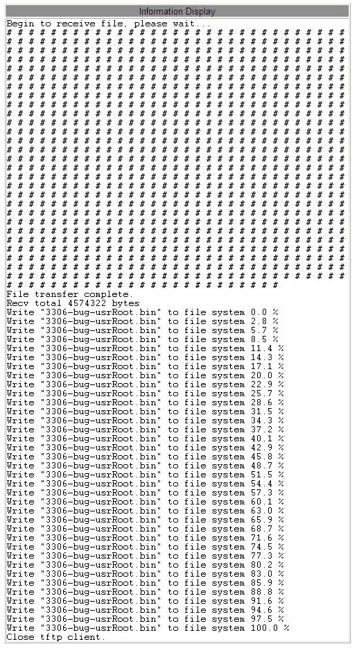
32 Figure 21: Normal communication of TFTP server and switch 4. Wait for the update to complete, as shown in Figure 22 Figure 22: Wait for update 5. When update completes as shown in Figure 23, please reboot the device and open the Switch Basic Information to check if update succeeded and the new version is active. 24
33 25
34 Figure 23: Software successfully update by TFTP Warning: In the software update process, keep the TFTP server software running When update completes, reboot the device to activate the new version If update fails, do not reboot the device, so as to avoid losing version file and switch can not start normally 26
35 5. Device Basic Configuration 5.1 Switch Basic Configuration Switch basic configuration includes hostname, mapping of host and IP address, Exec timeout and switch clock and other settings Basic Configuration 1. Set hostname Click [Device Basic Configuration] [Switch Basic Configuration] [Basic Config] to enter Hostname Configuration page, as shown in Figure 24. Figure 24: Set hostname Hostname Setting range: 1-30 characters Default: Device name Function: Set the prompt in switch CLI Method: Click <Apply> to activate the new hostname; click <Reset> to cancel current setting and use the previous hostname. 2. Set mapping of host and IP address, Click [Device Basic Configuration] [Switch Basic Configuration] [Basic Config] to enter Mapping hostname and IP page, as shown in Figure


36 Figure 25: Mapping of host and IP address Mapping hostname and IP Portfolio configuration: {Host name, IP address} Format: {1-15 characters, A.B.C.D} Function: According to the mapping relationship, use hostname to access the corresponding device. Method: Input valid hostname and IP address, click <Add>to set a mapping entry of hostname and IP address. Click <Del> to delete this mapping relationship entry. Example: After successfully setting the mapping relationship of the hostname Switch and the IP address , user can ping switch by using the command of ping Switch instead of ping in the switch CLI Set Exec Timeout In order to guarantee switch security and avoid malicious operation, set privileged mode timeout. Click [Device Basic Configuration] [ Switch Basic Configuration] [Set Exec Timeout] to enter the following page, as shown in Figure

37 Figure 26: Set the timeout of exiting privileged user configuration mode Timeout Configurable range: 0~300 minutes Default: 5 minutes Function: Start time begins when the privileged user finishes all configurations, and the system will automatically exit privileged mode when the time ends. Explanation: If set the timeout to 0, the system won t exit privileged mode Set Clock Set system date and time. This series of switches support RTC real time clock. Even if power is removed, switch still keeps time. Click [Device Basic Configuration] [Switch Basic Configuration] [clock config] to enter the clock setting page, as shown in Figure 27. Figure 27: Clock setting Clock Setting Portfolio configuration: {HH:MM:SS, YYYY.MM.DD} Configurable range: HH (hour) is in the range of 0~23; MM (minute) and SS (second) is in the range of 0~59; YYYY (year) is in the range of 2000~2100; MM (month) is in the range of 1-12; DD (day) is in the range of 1-31 Function: Set device RTC real time clock 29
38 5.2 Port Configuration Physical Port Configuration Introduction Physical port configuration can control cable type, management status, rate/mode and other information Web Configuration Click [Device Basic Configuration] [Port configuration] [Ethernet port configuration] [Physical port configuration] to enter the port configuration page, as shown in Figure 28. Figure 28: Physical port configuration Port Options: all switch ports Description: X/Y is the port format, X means the slot number for interface module where the port locates, this series products are not the modular devices, so X ==1. Y means the port number on the front panel. mdi Options: auto/normal/across Default: auto Function: Configure the cable type for Ethernet port Description: auto means auto-recognition of cable type; across means the port only supports cross-over cable, normal means the port only support straight through cable 30
39 Caution: The auto-recognition of cable type is recommended. Admin Status Options: shutdown/no shutdown Default: no shutdown Function: allow data transmission in port or not Description: no shutdown is to enable the port and allow data transmission. Shutdown means the port is disabled without data transmission. It can directly affect the hardware state of port and trigger port alarm. Speed/duplex status Options: auto, 10M/Half, 10M/Full, 100M/Half, 100M/Full, 1000M/Half, 1000M/Full Default: auto Function: configure port speed and duplex mode Description: Port speed and duplex mode support auto-negotiation and forced configuration. If it is set auto, the port speed and duplex mode will be automatically negotiated according to port connecting status. When the port duplex mode changes from auto-negotiation to forced full duplex or half duplex, the port speed will also be changed to forced mode. We recommend user to set auto negotiation of port speed and duplex mode, in order to avoid the connection problem caused by the unmatched port configuration on both ends of link. If user sets the port to forced speed or duplex, please ensure the speed or duplex mode configuration on two sides of connection are the same. Caution: The speed /mode of 10/100Base-TX port can be set to auto, 10M/Half, 10M/Full, 100M/Half, 100M/Full The speed/mode of 100Base-FX port can only be set to auto, 100M/Full The speed/mode of 10/100/1000Base-TX port can be configured to auto, 31

40 10M/Half, 10M/Full, 100M/Half, 100M/Full, 1000M/Half, 1000M/Full The speed/mode of Gigabit fiber port can only be set to auto, 1000M/Full Show port information based on Ethernet port configuration and communication conditions, as shown in Figure 29. Figure 29: Port list Show Port Information Click [Device Basic Configuration] [Port configuration] [Port debug and maintenance] [Show port information] to enter the port information displaying page. It shows port connecting status, port type, input/output packet statistics and other information, as shown in Figure
41 Figure 30: Port information 5.3 VLAN Configuration Introduction VLAN (Virtual Local Area Network) is to divide a LAN to multiple logic VLANs. The devices in a same VLAN can communicate to each other and the devices in different VLANs can not conduct intercommunication, so the broadcast messages are limited in a VLAN, highly improving LAN security. VLAN partition is not restricted by physical location. Each VLAN is regarded as a logical network. If a host in one VLAN wishes to send data packets to a host in another VLAN, a router or a layer 3 device must be involved. 33
42 5.3.2 Principle In order to let network device distinguish messages from different VLANs, fields to identify VLAN need to be added to the message. At present, the most common used protocol to identify VLAN is IEEE802.1Q protocol. The 802.1Q frame structure is shown in Table 3: Table 3: 802.1Q Frame Structure DA SA 802.1Q Header Type PRI CFI VID Length/Type Data FCS A 4 bytes 802.1Q header is added to the traditional Ethernet data frame and it becomes the VLAN Tag. Type: 16 bits. It is used to identify that the frame carries a VLAN Tag, and the value is 0x8100. PRI: three bits, mark message s 802.1p priority CFI: one bit. 0 means Ethernet, 1 means token ring network VID: 12 bits, VLAN number, ranges from 1 to , 4094 and 4095 are reserved by protocol. Note: VLAN 1 is the default VLAN and cannot be manually created and deleted by users. Reserved VLANs are reserved to realize specific functions by system and cannot be manually created and deleted by users. The message containing an 802.1Q header is a tagged message; if not, it is an untagged message. The messages in switch all carry an 802.1Q header Port-based VLAN VLAN partition contains multiple types, such as port-based, MAC address-based. This series switches support port-based VLAN partition that defines VLAN members based 34
43 on switch ports. It can add a port to the designated VLAN, and then this port can forward the designated VLAN messages. 1. Port Type According to the methods of port handling VLAN Tag during message forwarding, port can be divided to two types: Access port: the messages forwarded from this port do not have a VLAN Tag. Generally, access port is used to connect with the terminal equipment that does not support 802.1Q protocol. By default, all switch ports are Access ports and belong to VLAN1. Trunk port: When the PVID of the Trunk port is same as the VLAN ID of the message, the message is forwarded without a Tag; otherwise, the message is forwarded with a Tag. Trunk ports are generally used to connect network transmission devices. Caution: Access port allows only one VLAN with the default of VLAN 1, but Trunk port allows multiple VLANs. 2. PVID Each port has a PVID attribute. When a port receives an Untagged message, it will add a Tag into the message according to the PVID. The PVID of Access port is the ID of VLAN that the port belongs to, and it can not be configured. The PVID of Trunk port can be configured. If no setting, the port PVID is default to 1. According to port type and PVID, Table 4 shows port processing received and forwarded messages. Table 4: The Processing of port-received and port-forwarded messages Port Type Processing of Received Messages Received message is Received message is Processing of Forwarded Messages 35
44 untagged messages tagged message When VLAN ID and PVID are the same, Access Adding VLAN Tag receive this message Drop VLAN Tag and port with PVID When VLAN ID and forward the message PVID are different, drop this message When VLAN ID is same as PVID, When VLAN ID is in drop VLAN Tag the port VLAN ID list and forward the or is same as PVID, message Trunk Port Adding VLAN Tag with PVID receive this message When VLAN is not in the port VLAN ID list When VLAN ID is different from PVID, but this and is different from VLAN ID is port PVID, drop this permitted, keep message VLAN Tag and forward the message Web Configuration 1. Create or delete VLAN. Click [Device Basic Configuration] [VLAN configuration] [VLAN configuration] [Create/Remove VLAN] [VALN allocation] to enter the VLAN configuration page, as shown in Figure
45 Figure 31: Create/Delete VLAN VID Range: , the default VLAN ID is 1 Function: use different VLAN ID to distinguish different VLANs Description: this series of switches support max 4093 VLANs Method: Click <Add> to create VLAN; click <Remove> to delete the designated VLAN 2. Configure VLAN name. Click [Device Basic [VLAN Configuration] configuration] [VLAN configuration] [Create/Remove VLAN] [VLAN attribution configuration] to enter the VLAN name configuration page, as shown in Figure 32. Figure 32: VLAN name configuration VLAN ID Range: all created VLANs Function: Input the ID of VLAN that needs to change the name VLAN name Range: 1-11 characters Function: input the VLAN name corresponding to the designated VLAN ID VLAN Type Options: universal vlan Default: universal vlan After setting, the screen of VLAN ID Information lists the attribute information of all created VLANs, as shown in Figure

![(Trunk/Access)] to enter the port type configuration page, as shown in Figure 34.](/docs-images/94/118317192/images/46-2.jpg "Figure 34: Port type configuration Port Options: all switch ports Type Options: access/trunk Default: access Function: choose the type of the")
46 3. Configure port type. Figure 33: VLAN list Click [Device Basic [VLAN Configuration] configuration] [VLAN configuration] [Port type configuration] [Set port mode (Trunk/Access)] to enter the port type configuration page, as shown in Figure 34. Figure 34: Port type configuration Port Options: all switch ports Type Options: access/trunk Default: access Function: choose the type of the designated port Description: access port allows one VLAN Trunk port allows multiple VLANs After setting, the screen of Port mode configuration lists all port types, as shown in Figure


47 Figure 35: Show port types 4. Assign Access ports to the created VLANs. Click [Device Basic [VLAN Configuration] configuration] [VLAN configuration] [Allocate ports for VLAN] [Allocate ports for VLAN] to enter the Access port VLAN configuration page as shown in Figure 36: 5. Configure Trunk port s PVID. Figure 36: Allocate access ports to VLANs Click [Device Basic [VLAN Configuration] configuration] [VLAN configuration] [Trunk port configuration] [VLAN setting for trunk port] to enter Trunk port VLAN configuration page, as shown in Figure 37 Figure 37: Trunk port PVID configuration Trunk Port Options: all Trunk ports Trunk Native Vlan (pvid) 39

48 Options: all created VLANs Default: 1 Function: Configure PVID for Trunk port Method: click <Default> to restore the PVID of selected Trunk port to 1 6. Configure VLANs for Trunk port, as shown in Figure 38 Figure 38: Configure VLANs for Trunk port Trunk Port Options: all Trunk ports Trunk Allow VLAN List Options: all created VLANs Default: all created VLANs Function: Configure VLANs for the selected Trunk port After setting, all Trunk ports VLAN attribute information is shown in Figure 39 Figure 39: Show Trunk port s VLAN configuration 7. Configure VLAN ingress rule for a port. Click [Device Basic [VLAN Configuration] configuration] [VLAN configuration] [Enable/Disable VLAN ingress rule] to enter the VLAN ingress rule configuration page, as shown in Figure

49 Figure 40 Configuring VLAN Ingress Rule Options: Enable/Disable Default: Enable Function: Enable or disable the VLAN ingress rule for a port. Description: If this function is enabled, the port checks the VLAN ID of a packet against its allowed VLAN list upon receiving the packet. If a match is found, the port forwards the packet; otherwise, the packet is discarded. If this function is disabled, the port forwards all packets without checking their VLAN IDs. After setting, all VLAN ingress rule informations are shown in Figure 41. Figure 41 VLAN Ingress Rule Information 8. Show all created VLAN information. Click [Device Basic Configuration] [VLAN configuration] [VL AN debug and maintenance] [Show VLAN] to enter the VLAN information displaying page, as shown in Figure 42: 41
50 Figure 42: Show VLAN information Typical Configuration Example As Figure 43 show, the entire LAN is divided into 3 VLANs: VLAN2, VLAN100 and VLAN200. It is required that devices in a same VLAN can communicate to each other and different VLANs are isolated from each other. The terminal PC devices cannot distinguish the messages with Tag, so the ports on Switch A and Switch B that connect with PCs are set to Access ports. VLAN2, VLAN100 and VLAN200 messages need to be transmitted between Switch A and Switch B, so the ports connecting Switch A and Switch B should be set to Trunk ports to let the messages travel through. The specific configuration is shown in Table 5. Table 5: VLAN configuration VLAN VLAN2 VLAN100 VLAN200 Configuration Set A and B switches 1 and 2 ports to Access, port 7 to Trunk Set A and B switches 3 and 4 ports to Access, port 7 to Trunk Set A and B switches 5 and 6 ports to Access, port 7 to Trunk 42

51 Figure 43: VLAN Application Switch A and Switch B configuration process: 1. Create VLAN2, VLAN100 and VLAN200, as shown in Figure Configure port 1, 2, 3, 4, 5, 6 to Access port, and port 7 to Trunk port, as shown in Figure Assign port 1, 2 to VLAN2, port 3, 4 to VLAN100, port 5, 6 to VLAN200, as shown in Figure Allow all VLAN messages to pass through port 7, as shown in Figure Port Mirroring Introduction Port mirroring is that switch copy all received and transmitted data frames in a port (mirroring source port) to another port (mirroring destination port). The mirroring destination port can connect with a protocol analyzer or RMON monitor for network monitoring, management and fault diagnosis. 43

52 5.4.2 Explanation Switch supports only one mirroring destination port, but there is no restriction on mirroring source port and supports one or multiple source ports. Multiple source ports can be in the same VLAN, or in different VLANs. Mirror source port and destination port can be in the same VLAN or in different VLANs. Source port and destination port cannot be the same port. Caution: Mirroring destination port and port channel are mutually exclusive. The port that is in port channel cannot be set to a mirror destination port, and the mirroring destination port cannot be added into a port channel WEB Configuration 1. Choose mirroring source port and mirroring mode. Click [Device Basic Configuration] [Port mirroring configuration] [Mirror configuration] to enter the mirroring source port configuration page, as shown in Figure 44. Figure 44: Mirror source port configuration Session Currently, it only supports 1 Mirror Direction Options: rx/tx/both 44

53 Default: both Function: choose data to be mirrored in the mirroring source port Description: rx only mirror the received messages in source port tx only mirror the transmitted messages in source port both mirror all messages in source port Source port Options: all switch ports Function: choose mirror source port, and it supports multiple source ports 2. Choose mirror destination port, as shown in Figure 45 Figure 45: Mirror destination port configuration Session Currently, it only supports 1 Destination port Options: all ports other than source port Function: choose mirror destination port Description: choose a port to be a mirroring destination port. There is only one mirroring destination port. The mirroring destination port cannot be a member of a port channel, and it is better that the destination port throughput is larger or equal to total throughputs of its source ports Typical Configuration Example As Figure 46 shows, the mirroring destination port is 2 and the mirroring source port is 1. All message on port 1 are mirrored to port 2 45
54 Figure 46: Port mirroring example Configuration process: 1. Set port 2 to mirror destination port, as shown in Figure Set port 1 to mirror source port and the port mirroring mode is set to both, as shown in Figure Port Storm Control Introduction Port storm control is to limit the port-received broadcast/unknown multicast/unknown unicast messages. When the port-received broadcast/unknown multicast/unknown unicast flow exceeds the user configured threshold, the system will drop the excess broadcast/unknown multicast/unknown unicast messages; so as to lower the port received broadcast/unknown multicast/unknown unicast message flow to an allowable range, ensuring normal network operation Web Configuration 1. Port storm control threshold configuration. Click [Device Basic Configuration] [Port Storm Suppression configuration] [Port Storm Suppression configuration] to enter the configuration page, as shown in Figure
55 Figure 47: Port storm control threshold configuration Port name Options: all switch ports Function: select the ports that need to limit the flow Rate unit: Options: bps/kbps Function: select the unit of the limited threshold. Rate Value: Function: Configure the threshold of port rate limit and the value range depends on the actual port speed, see Table 6. When the value is 0, the port storm control is disabled. By default, the storm control is disabled. Table 6: Value range of port rate limit Port Rate Threshold Unit Step Length Value range 10M 100M 1000M bps kbps Not recommend Not recommend bps kbps bps kbps Choose the type of message to control, as shown in Figure 48 Port name Figure 48: Configure the message to limit the rate Options: all ports that enable port storm control function 47
56 Suppression Type Options: Multicast/broadcast/dlf Function: select the type of message to control Function Options: Enable/Disable Default: Disable Function: limit the selected message or not Note: One port has one limit rate threshold that can limit the rate of port storm control-enabled message Typical Configuration Example Enable the unknown multicast storm control on on port 1/1 with the bandwidth threshold of 1000kbps Configuration steps: Choose port 1/1; rate unit kbps, rate value 1000kbps, as shown in the Figure 47; Select message type multicast as shown in the Figure Port Channel Introduction Port channel is to treat a group of ports that have same attribute configuration as a logical port to increase bandwidth and improve transmission speed. The member ports in a same group share traffics and they are dynamic backups to each other, improving connection reliability. Port group is a physical port group on the configuration layer. Only the physical ports 48
57 that join in Port group can participate in link aggregation and become a member of Port Channel. When physical ports in a Port Group meet certain conditions, they can conduct port aggregation and form a port channel and become an independent logical port, not only increasing network bandwidth, but also providing link backup function Implementation As Figure 49 shows, three ports in Switch A and Switch B are aggregated and form a Port Channel. The bandwidth of port channel is the total bandwidth of three ports. Figure 49: Port channel If traffic from Switch A would like to be transmitted to Switch B through Port channel, the port channel will conduct traffic distribution calculation in Switch A according to the traffic sharing mode, then decide a member in port channel to undertake this traffic according to calculation results. If a port is disconnected in Port channel, the traffic that the port undertakes will be distributed to other ports after traffic distribution is calculated Explanation This series of switches support forming port group in any two physical ports, along 49
58 with max 8 port groups and each group contains max 8 member ports. Port group and mirroring destination port are mutually exclusive. A port that is in port group cannot be configured to a mirroring destination port and the mirroring destination port cannot join a port group. Caution: A port can only join one port group Web Configuration 1. Configure traffic sharing mode of Port Channel. Click [Device Basic Configuration] [Port channel configuration] [LACP port group configuration] to enter the configuration page, as shown in Figure 50. Figure 50: Traffic sharing mode configuration Load balance mode Options: mac-only/ip-only/mac-ip/ip-l4/mac-ip-l4 Default: mac-only Function: set the traffic sharing mode of port channel Description: mac-only: traffic sharing according to MAC address; ip-only, traffic sharing according to IP address; mac-ip: traffic sharing according to MAC address and IP address. ip-i4: traffic sharing according to IP address and TCP/UDP port number; mac-ip-14: traffic sharing according to MAC address, IP address and TCP/UDP port number Explanation: If traffic sharing mode would like to be changed and this port-group has formed a port-channel, the change will take effect after the next aggregation. 50


59 2. Create or delete a port group, as shown in Figure 51 Figure 51: Port channel configuration LACP group number Range: 1-8 Function: set the port group number with max 8 port groups Operation type Options: add port group/remove port group Default: add port group Function: create/delete port group After setting, the port group table show all created port groups and load sharing mode, as shown in Figure Port group member configuration. Figure 52: Port group list Click [Device Basic Configuration] [Port channel configuration] [LACP port configuration] to enter the configuration page, as shown in Figure
60 Figure 53: Port group member configuration LACP group number Options: all created port group numbers Port Options: all switch ports Function: choose the port to be added to or deleted from a port group Description: the member ports in a same port group have same port attribute; max 8 ports in a group Port mode: Options: on Default: on Function: configure the member port mode Description: on: manually add port to port channel Explanation: the modes of port adding into a Port Group must be the same, and it is subject to the mode of the first port adding into the group. Operation type Options: Add port to group/remove port from group Default: Add port to group Function: select port to add to or remove from Port group Typical Configuration Example As Figure 49 shows, three ports (port 1, 2, 3) of Switch A add into Port Group 1; three ports (port 1, 2, 3) of switch B add into Port Group 2. Use network cables to respectively connect above ports and form a Port channel, realizing traffic sharing between ports. (it is assumed that three aggregation ports on Switch A and B have same attributes) Switch configuration steps: 1. Add Port Group 1 into Switch A, as shown in Figure Add port 1, 2, 3 into port group 1 in on mode, as shown in Figure 52 52

61 3. Add Port Group 2 into Switch B, as shown in Figure Add port 1, 2, 3 into Port Group 2 in on mode, as shown in Figure User Management of Telnet Server Introduction Telnet remote login is a simple remote terminal protocol. User can use Telnet to log into a remote host (using IP address or host name) via TCP connection. Telnet can transmit user s keystroke to remote host and send the remote host s transmitted information back to user screen via TCP connection. Telnet uses client-server mode. The local system is Telnet client and remote host is Telnet server. This series of switches can be Telnet server and Telnet client. When switch serves as Telnet server, user can log on switch by Telnet client software of Windows or other operating system. When switch serves as Telnet server, it can establish TCP connection with max 5 Telnet clients at the same time. When switch works as Telnet client, telnet command can be used to log into other remote host under the privileged mode of the switch. When switch works as Telnet client, it can only make TCP connection with one remote host. If switch wishes to establish connection with another remote host, it must disconnect the created TCP connection first WEB Configuration 1. Enable switch Telnet server function. Click [Device Basic Configuration] [Telnet server configuration] [Telnet server user configuration] to enter the configuration page, as shown in Figure 54. Figure 54: Telnet server configuration 53
62 Telnet server state Configuration items: open/close Default: open Function: open/close switch Telnet server function Description: Open means that Telnet client can log into the switch. Close means that Telnet client cannot log into the switch Note: When this function is open or closed, switch works as Telnet client and use Telnet command to log into other remote host. 2. Configure user name and password used when Telnet client log into the switch, as shown in Figure 55. Figure 55: Configure Telnet server username and password {Username, Password} Range: {1-16 characters, 1-8 characters} Default: {admin, 123} Function: Configure username and password used when Telnet client log into the switch. It is used to configure authorized Telnet client when switch works as Telnet server. Description: Default user name and password is {admin, 123}. If switch works as Telnet server, it allows establishing TCP connection with max 5 Telnet clients at the same time. State Options: Plain text/encrypted text 54

63 Default: Plain text Function: choose the password displaying way 3. Configure security IP address for Telnet client login. Click [Device Basic Configuration] [Telnet server configuration] [Telnet security IP] to enter the configuration page, as shown in Figure 56. Figure 56: Telnet server security IP Security IP address Format: A.B.C.D Function: Configure security IP address for Telnet client login when switch works as Telnet server. Description: If do not set security IP, there is not restriction on Telnet client s IP address. After setting security IP address, only the client with a security IP address can log into and configure switch by Telnet. A switch allows max 32 security IP addresses. By default, there is not security IP address. After setting, the Telnet server Security IP list show Telnet client IP addresses that can log into switch, as shown in Figure 57. Figure 57: Security IP address list 55

64 5.8 User Management of Web Server Introduction When switch works as Web server, user can log in switch by browser. When Switch works as Web server, it can establish connection with multiple Web clients at the same time. The default username is admin and password is 123 when Web client logs into switch. This default user cannot be deleted, but its password can be changed WEB Configuration 1. Configure Web login user name and password. Click [Device Basic Configuration] [Web server user configuration] [Web server user configuration] to enter Web user configuration page, as shown in Figure 58. Figure 58: Web user configuration {Username, Password} Range: {1-16 characters, 1-8 characters} Default: {admin, 123} Function: configure username and password when Web client logs into switch. State Configuration: Plain text/encrypted text Function: choose the password displaying way After setting, the User Name Configured list shows all user names and passwords used to log into switch by Web, as shown in Figure
 are changed, user can use file transmission to obtain the original files from the server (client) by FTP/TFTP protocol.")
65 Figure 59: Web user list 5.9 File Transmission Service File transmission service can realize mutual backup of files in the client and server. When files in the client (server) are changed, user can use file transmission to obtain the original files from the server (client) by FTP/TFTP protocol. Switch not only can work as client, but also server to upload or download files by FTP/TFTP protocol TFTP Service 1. Switch works as TFTP client First, install TFTP server, as shown in Figure 60. In Current Directory, browse the file storage path in server; input server IP address in Server interface 57
![Figure 60: TFTP server configuration Click [Device Basic Configuration] [File transmit] [TFTP Service] [TFTP client service] to enter TFTP client configuration page, as shown in Figure 61.](/docs-images/94/118317192/images/66-1.jpg "Figure 61: TFTP client service Server IP address Format: A.B.C.")
66 Figure 60: TFTP server configuration Click [Device Basic Configuration] [File transmit] [TFTP Service] [TFTP client service] to enter TFTP client configuration page, as shown in Figure 61. Figure 61: TFTP client service Server IP address Format: A.B.C.D Description: input server IP address Local file name Range: characters Description: the file name in switch Server file name Range: characters 58

67 Description: the file name in server Transmission type: Configuration items: binary/ascii Default: binary Function: choose the file transmission standard Explanation: ascii means using ASCII standard to transmit file; binary means using binary standard to transmit file Method: click <Upload to PC> to upload the file from switch to server, click <Download to Device> to download file from server to switch When file transmission succeeds, the following information appears on Web interface, as shown in Figure 62 and Figure 63 Figure 62: TFTP client successful upload file Figure 63: TFTP client successful download file Caution: In the file transmission process, keep TFTP server running. 2. Switch works as TFTP server Click [Device Basic Configuration] [File transmit] [TFTP Service] [TFTP server service] to enter TFTP server configuration page, as shown in Figure
68 Figure 64: TFTP server service Server state Configuration items: Close/open Default: close Function: enable/disable the function of switch working as TFTP server TFTP Timeout Range: s Default: 20s Function: configure the timeout of TFTP server connection TFTP Retransmit times Range: 1-20 Default: 5 Function: configure the times of TFTP server retransmitting data during timeout Install TFTP client software, as shown in Figure 65. Input switch IP address in Host; choose the client file storage path in Local File; input the file name saved in switch in Remote File; click <Get> to download file from switch to client, click <Put> to upload client file to switch 60

69 Figure 65: TFTP client configuration Caution: During file transmission, keep TFTP client software running FTP Service 1. Switch works as FTP client First, install FTP server, click [Security] [users/rights] to open the dialog box, click<new user> to create a new FTP user, as shown in Figure 66, input username and password, such as, username: admin; password: 123, click <OK> 61

70 Figure 66: Create FTP new user Input the file storage path in server in Home Directory, as shown in Figure 67, click <Done> Figure 67: File storage path 62
![Click [Device Basic Configuration] [File transmit] [FTP Service] [FTP client service] to enter FTP client configuration page, as shown in Figure 68.](/docs-images/94/118317192/images/71-0.jpg "Figure 68: FTP client service Server IP address Format: A.B.C.")
71 Click [Device Basic Configuration] [File transmit] [FTP Service] [FTP client service] to enter FTP client configuration page, as shown in Figure 68. Figure 68: FTP client service Server IP address Format: A.B.C.D Description: input server IP address {User name, Password} Range: {1-100 characters, characters} Description: the username and password created on FTP server Local file name: Range: characters Description: the file name in switch Server file name Range: characters Description: the file name in server Transmission type: Configuration items: binary/ascii Default: binary Function: choose the file transmission standard Explanation: ascii means using ASCII standard to transmit file; binary means using binary standard to transmit file Method: click <Upload to PC> to upload the file from switch to server, click 63


72 <Download to Device> to download file from server to switch. When file transmission succeeds, the following information appears on Web interface, as shown in Figure 69 and Figure 70. Figure 69: FTP client successful upload file Figure 70: FTP client successful download file Caution: In the file transmission process, keep FTP server software running. 2. Switch works as FTP server Click [Device Basic Configuration] [File transmit] [FTP Service] [FTP ser ver service] to enter FTP server configuration page, as shown in Figure 71. Figure 71: FTP server service 64
73 FTP Server state Options: Close/open Default: close Function: Open/Close switch FTP server function FTP Timeout Range: s Default: 600s Function: configure the timeout of FTP server connection Description: start time begins once FTP server is connected successfully. When the time ends, the connection will be cut off. Configure the username and password used to log into FTP server, as shown in Figure 72. Figure 72: FTP server user name and password configuration {Username, Password} Range: {1-16 characters, 1-8 characters} Default: {admin, 123} Function: configure the username and password used to log into FTP server Description: when switch works as FTP server, it can connect with multiple FTP clients at the same time State Options: Plain text/encrypted text Default: Plain text Function: choose the password displaying way Click [Start] [Run] in Windows system to open the dialog box, input cmd to open CLI, as shown in Figure 73 65
74 Figure 73: cmd CLI The file transmission path can be changed. Log in FTP server, as shown in Figure 74 Figure 74: FTP server connection Use configured user name admin and password 123 to log into FTP server, as shown in Figure 75 66
75 Figure 75: login FTP server Use the get command to download switch file to designated path on client, as shown in Figure 76. Input get command and press Enter, input the name of file on switch that need to be downloaded in Remote file, input the file name saved in client in Local file Figure 76: Download file from switch to client 67

76 Use the put command to upload the file in the designated path in client to server, as shown in Figure 77, input put command, press Enter, input the file name in switch in Remote file, input the name of file in client that need to be uploaded in Local File Figure 77: Upload file from client to switch 5.10 MAC Address Configuration Introduction When a switch forwards a message, it searches the port number corresponding to the destination MAC address of the message in MAC address table, and then forwards the message from this port. MAC address is divided into static MAC address and dynamic MAC address. Static MAC address is configured by user and has highest priority (cannot be covered by dynamic MAC address) and is permanently valid. Dynamic MAC address is learned by switch in the process of forwarding data frames, and is valid in a limited time, and it is renewed regularly. When a switch receives the data frames that need to be forwarded, it learns the source MAC address of the data 68
77 frame, and establishes a mapping relationship with the receiving port, and then searches the destination MAC address in the MAC address table. If there is a corresponding entry, switch will forward the data frame to corresponding port. Otherwise, switch will broadcast the data frame in the broadcast domain that the switch belongs to. Aging time starts from an address adding into address table. If all ports do not receive the frame with this source address within once to twice aging times, this entry will be deleted from dynamic forwarding address table. Static MAC address is not affected by aging time. The switch supports max 1024 static unicast entries Web Configuration 1. Adding static unicast MAC address. Click [Device Basic Configuration] [MAC address configuration] [Unicast address configuration] to enter unicast MAC address configuration page, as shown in Figure 78. Figure 78: Adding static FDB table MAC address Format: FF-FF-FF-FF-FF-FF (F is a hexadecimal number) Function: configure unicast MAC address and the lowest bit in the first byte is 0 VLAN ID Options: all created VLAN IDs Default: VLAN1 69

78 Configuration type Options: static/blackhole Default: static Function: select the attribute of MAC address entry Description: static means establishing mapping relationship of the designated MAC address with port number or VLAN ID; blackhole is to drop the message whose source MAC address or destination MAC address is the designated MAC address. Port list Options: all switch ports Function: choose ports to forward the message with this destination MAC address; the selected ports must be in the VLAN designated above. 2. Delete unicast address. Click [Device Basic Configuration] [MAC address configuration] [Delete unicast address] to enter the configuration page, as shown in Figure 79 Figure 79: Delete unicast MAC address Choose the criterion to delete unicast address. If choose multiple criteria, they are in and relation 3. Configure MAC address aging time. Click [Device Basic Configuration] [MAC add ress configuration] [MAC address aging time setting] to enter the aging time configuration page, as shown in Figure 80 70

79 Figure 80: MAC address aging time configuration Aging time Range: s Default: 300s Function: set the aging time for the dynamic MAC address entry Description: When aging time is 0, aging is prohibited. That means the address that is dynamically learned won t age over time. 4. Unicast MAC address query. Click [Device Basic Configuration] [MAC address configuration] [MAC address query] to enter the unicast MAC address query page, as shown in Figure 81. Figure 81: Unicast MAC address query Choose the criterion of unicast MAC address query. If choose multiple criteria, they are in and relation. For example: inquire the port1/1 s corresponding MAC address table, as shown in Figure Show unicast address entries. Figure 82: Unicast MAC address query Click [Device Basic Configuration] [MAC address configuration] [ Show 71
![mac-address table] to enter the unicast MAC address query page that show all dynamic and static entries, as shown in Figure 83. Figure 83: Unicast address query 5.](/docs-images/94/118317192/images/80-0.jpg "11 Basic Configuration Maintenance and Debugging Information When user configures switch, it is needed to check whether all configurations are correct and whether switch works normally as required.")
80 mac-address table] to enter the unicast MAC address query page that show all dynamic and static entries, as shown in Figure 83. Figure 83: Unicast address query 5.11 Basic Configuration Maintenance and Debugging Information When user configures switch, it is needed to check whether all configurations are correct and whether switch works normally as required. When failover occurs on the network, user needs to diagnose faults. User can check system configuration, operation status and other information by the following operation. 1. Ping operation. Click [Device Basic Configuration] [ Basic configuration debug] [Ping and Traceroute] to enter ping operation page, as shown in Figure


81 Figure 84: Ping operation IP address Format: A.B.C.D Description: input the IP address of remote device Hostname Range: 1-30 characters Function: If the mapping relation of remote host and IP address has been set, just input the remote host name and conduct Ping operation Description: the switch sends ICMP request packets to the remote device to detect the communication between switch and remote device. 2. Traceroute operation configuration, as shown in Figure 85. Figure 85: Traceroute operation IP address Format: A.B.C.D Description: input the IP address of remote device Hostname Range: 1-30 characters Function: if the mapping relation of remote host and IP address has been set, only need to input the remote host name to conduct Traceroute operation Hops 73
82 Options: Function: Test the number of gateways that the packet travels through from the sending device to the destination device Timeout Options: ms Function: Configure the timeout. If the sending device does not receive the responding message from the receiving device within this time, it is considered that the communication fails. 3. Show system date and time. This series switches support RTC real time clock. Even the power is cut off, the timekeeping continues. Click [Device Basic Configuration] [Basic configuration debug] [show clock] to enter clock show page, as shown in Figure Show the file information in Flash. Figure 86: Show clock Click [Device Basic Configuration] [Basic configurati on debug] [show flash] to enter flash show page, as shown in Figure 87. Figure 87: Show flash 5. Show operation configuration information that is the configuration parameters in effect after modification. 74
![Click [Device Basic Configuration] [Basic configuration debug] [show running-config] to enter operation configuration page, as shown in Figure 88. 6.](/docs-images/94/118317192/images/83-1.jpg "Show port information Figure 88: Show operation configuration information Click [Device Basic Configuration] [Basic confi guration debug] [show switchport-config] to enter show port information page,")
83 Click [Device Basic Configuration] [Basic configuration debug] [show running-config] to enter operation configuration page, as shown in Figure Show port information Figure 88: Show operation configuration information Click [Device Basic Configuration] [Basic confi guration debug] [show switchport-config] to enter show port information page, as shown in Figure 89. Type Description: the port type Figure 89: Show port information 75
84 Mode Description: the port VLAN mode Port VID Description: the port PVID Trunk allowed Vlan Description: VLAN list that can pass through Trunk port 7. Show the TCP connection status established in switch. Click [Device Basic Configuration] [Basic configuration debug] [show tcp] to enter TCP connection information page, as shown in Figure 90. Figure 90: Show TCP connection Local Address Description: the local address of TCP connection Local Port Description: the local port number of TCP connection Foreign Address Description: the address in the other end of TCP connection Foreign Port 76

85 Description: the number of port in the other end of TCP connection State Description: the current state of TCP connection 8. Show UDP connection status established with switch. Click [Device Basic Configuration] [Basic configuration debug] [show udp] to enter UDP connection information page, as shown in Figure 91. Figure 91: Show UDP connection information Local Address Description: the local address of UDP connection Local Port Description: the local port number of UDP connection Foreign Address Description: the IP address in the other end of UDP connection Foreign Port Description: the number of port in the other end of UDP connection, State Description: the current state of UDP connection 9. Show the information of Telnet client that establish Telnet connection with switch. Click [Device Basic Configuration] [Basic configuration debug] [show telnet login] to enter Telnet user displaying page, as shown in Figure 92. Figure 92: Show Telnet users 77
86 6. Device Advanced Configuration 6.1 ARP Configuration Introduction ARP (Address Resolution Protocol) uses address request and response mechanism to resolve the mapping relationship of IP address and MAC address. Switch can dynamically learn the IP address-and-mac address mapping relationship of other hosts that are in a same segment with the switch, and it can fix the mapping relationship of IP address and MAC address by static ARP entry configuration. Dynamic ARP entry requires aging at a fixed period to ensure its correctness in practical application. This series switches only provides layer 2 switching function, but they support ARP function to realize the IP address resolution of other hosts that are in a same segment with switch, achieving intercommunication with network management system and other management hosts Explanation ARP entries are divided to dynamic ARP entries and static ARP entries. Dynamic entries are automatically generated and maintained by ARP message exchange. They can be aged and renewed by new ARP messages and covered by static ARP entries. Static entries are manually configured and maintained. They cannot be aged and covered by dynamic ARP entries. Max 8192 ARP entries are supported. When the number exceeds 8192, the new entry will cover the old dynamic entry. 78
![6.1.3 Web Configuration 1. Add or delete static ARP entry. Click [Device Advanced Configuration] [ARP configuration] [ARP configuration] to enter the ARP configuration page, as shown in Figure 93.](/docs-images/94/118317192/images/87-0.jpg "Figure 93: Co")
87 6.1.3 Web Configuration 1. Add or delete static ARP entry. Click [Device Advanced Configuration] [ARP configuration] [ARP configuration] to enter the ARP configuration page, as shown in Figure 93. Figure 93: Configure static ARP entry IP address Format: A.B.C.D Function: Configure IP address of static ARP entry MAC address Format: FF-FF-FF-FF-FF-FF (F is a hexadecimal number) Function: configure MAC address of static ARP entry Operation type Options: Add/Del Default: Add Function: Add or delete ARP entry L3 interface Options: all created layer 3 VLAN interfaces Default: VLAN1 Function: choose the layer 3 VLAN interface for the current ARP entry Ethernet Port Options: all ports in the designated VLAN 79

88 Function: choose the out port corresponding to the current ARP entry Caution: Before static ARP entry configuration, the static binding IP address can not be switch IP address Different IP addresses can bind to a same MAC address Through setting port s Trunk attribute, a ARP entry can bind to different VLAN attributes In a VLAN, a ARP entry only corresponds to one forwarding port Generally, switch automatically learns ARP entries without the need of static entry configuration by administrator 2. Show ARP address entry. Click [Device Advanced Configuration] [ARP configuration] [Show ARP] to show the ARP configuration, as shown in Figure 94. Figure 94: ARP list ARP list Portfolio displaying: {IP address, MAC address, L3 interface, Ethernet port, Type} Function: show ARP entries Description: ARP list shows all ARP entries corresponding to LinkUp ports, including static entries and dynamic entries 3. Clear ARP cache. Click [Device Advanced Configuration] [ARP configuration] [Clear ARP cache] to clear ARP cache, as shown in Figure

89 Figure 95: Clear ARP cache Click <Apply> to clear dynamic ARP entries in cache. 6.2 Layer 3 interface configuration Show Switch IP address When logging into switch by Console port, input enable in CLI to switch from general mode to privileged mode, then input show interface vlan 1 to show switch IP address. As Figure 96 shows, the IP address is circled in red. Figure 96: Show IP address 81

90 6.2.2 IP Address Configuration 1. Create layer 3 VLAN interface Hosts in different VLANs cannot communicate to each other, requiring router, Layer 3 switch or other network device to forward data. Layer 3 forwarding is achieved by VLAN interface. This series switches support Layer 3 VLAN interface. It is a virtual interface in layer 3, not a physical port in device, and is mainly used for Layer 3 intercommunication between VLANs. Each VLAN can create a layer 3 VLAN interface that can perform network layer forwarding of port-received messages in the VLAN. Click [Device Advanced Configuration] [L3 interface configuration] [Add interface VLAN] to enter the configuration page, as shown in Figure 97. Figure 97: Create VLAN interface Interface vlan ID Options: all created VLAN numbers Default: 1 Function: create layer 3 VLAN interface Note: Switch supports max 16 layer 3 VLAN interfaces Before creating VLAN interface, please ensure the existence of the 82

91 corresponding VLAN. If the VLAN does not exist, its VLAN interface can not be created Cannot delete the VLAN interface whose corresponding IP address is used to access switch by Web 2. IP address obtainment Switch IP address can be manually configured and be automatically obtained. Click [Device Advanced Configuration] [L3 interface configuration] [L3 port IP address mode configuration] to enter the IP address configuration page, as shown in Figure 98. Figure 98: IP address obtainment Port Options: all created layer 3 VLAN interfaces Default: VLAN1 IP Mode Options: bootp-client/dhcp-client/specify IP address Default: Specify IP address Function: select the mode to obtain IP address Description: Specify IP address is to manually configure IP address; bootp-client/dhcp-client is that the switch automatically obtain IP address by DHCP/BOOTP protocol. There should be a DHCP/BOOTP Server in the network to assign IP address to client 3. Manually configure IP address Click [Device Advanced Configuration] [L3 interface configuration] [Allocate IP address for L3 port] to allocate IP address, as shown in Figure
 is a framework to manage devices in the network by using TCP/IP protocol suite.")
92 Figure 99: IP address configuration Status Options: no shutdown/ shutdown Default: no shutdown Function: configure the state of layer 3 VLAN interface Description: no shutdown: open the layer 3 VLAN interface shutdown: close the layer 3 VLAN interface Note: Each layer 3 VLAN interface can configure max 32 IP addresses. 6.3 SNMP Introduction SNMP (Simple Network Management Protocol) is a framework to manage devices in the network by using TCP/IP protocol suite. Network administrator can use SNMP function to check device information, modify device parameters, monitor device status and locate network faults, and so on Implementation SNMP protocol adopts manager/agent mode, so SNMP network contains NMS and Agent. 84
93 NMS (Network Management Station) is a workstation running the client program of the SNMP-supported network management software, playing a core role in SNMP network management. Agent is a process in the managed device. It is responsible for receiving, processing the request messages from NMS. When alarm is triggered, Agent will automatically inform the NMS. NMS manages SNMP network while Agent is managed by SNMP network. The management information exchange between NMS and Agent is through SNMP protocol. SNMP provides 5 basic operations: Get-Request Get-Response Get-Next-Request Set-Request Trap NMS sends query and configuration requests to Agent by Get-Request, Get-Next-Request and Set-Request messages. When Agent receives request, it will send out Get-Response message as respond. When alarm is triggered, Agent will automatically send Trap message to NMS to inform the occurrence of abnormal events Explanation SNMP Agent of this series device supports SNMP v2 version which is compatible with SNMP v1. SNMP v1 adopts Community Name Authentication. Community name plays a role of password and is used to restrict SNMP NMS accessing SNMP Agent. If a SNMP message carries a community name that cannot pass device authentication, this message will be dropped. SNMP v2 also adopts community name authentication. It not only is compatible with SNMP v1, but also expands the functions of SNMP v1. 85

94 The matched SNMP version is the precondition of successful information exchange between NMS and Agent. Agent can be configured with multiple versions at the same time, and uses different version to communicate with different NMS MIB Introduction Any managed resource can be viewed as an object and it is called a managed object. MIB (Management Information Base) is a collection of managed objects. It defines the hierarchical relationships between managed objects and defines a series of attributes of objects, such as object s name, access rights, data types, and so on. Each Agent has its own MIB. NMS can read or write objects in the MIB according to its rights. The relationship of NMS, Agent and MIB is shown in Figure 100. Figure 100: NMS, Agent and MIB relationship MIB defines a tree structure and each tree node indicates a managed object. Each node contains a sole OID (Object Identifier). OID indicates node s position in the MIB tree structure, as shown in Figure 101. The OID of the managed object A is Figure 101: MIB tree structure 86
![6.3.5 Web configuration 1. Enable SNMP Protocol. Click [Device Advanced Configuration] [SNMP Configuration] [Enable SNMP Agent] to enable SNMP agent, as shown in Figure 102.](/docs-images/94/118317192/images/95-2.jpg "Snmp Agent state Options: Open/Close Default: Close Function: Enable/Disable SNMP protocol 2. Configure access rights.")
95 6.3.5 Web configuration 1. Enable SNMP Protocol. Click [Device Advanced Configuration] [SNMP Configuration] [Enable SNMP Agent] to enable SNMP agent, as shown in Figure 102. Snmp Agent state Options: Open/Close Default: Close Function: Enable/Disable SNMP protocol 2. Configure access rights. Figure 102: Enable SNMP Click [Device Advanced Configuration] [SNMP Configuration] [SNMP Manager Configuration] to enter SNMP rights configuration page, as shown in Figure 103. Figure 103: Access rights configuration Community String Range: 1~255 characters Function: configure switch community string Description: Only when the community name carried in the SNMP message is same as this community string can the message access switch MIB. 87

96 Explanation: Max 4 community strings can be set Access Priority Options: Read only/read and write Default: Read only Function: Configure the MIB access mode Description: Read only: only read MIB information Read and write: read and write MIB information State Options: Valid/Invalid Default: Invalid Function: choose the configuration validity Method: Select Invalid to delete the corresponding community string 3. Security IP address configuration. Click [Device Advanced Configuration] [SNMP Configuration] [Set IP Address of SNMP Manager] to enter security IP address configuration page, as shown in Figure 104. Figure 104: Security IP address configuration Security ip address Format: A.B.C.D Function: configure the security IP address of NMS Description: Only the NMS whose IP address is the security IP address can access switch MIB 88

97 Explanation: max 6 security IP addresses can be set State Options: Valid/Invalid Default: Invalid Function: choose validity of the security IP address Method: select Invalid to delete the corresponding IP address 4. Trap Configuration. Click [Device Advanced Configuration] [SNMP Configuration] [Trap Manager Configuration] to enter Trap configuration page, as shown in Figure 105. Figure 105: Trap configuration Trap receiver Format: A.B.C.D Function: configure the IP address of Trap server Explanation: max 4 valid Trap server IP addresses can be set Community String Range: 1~255 characters Function: configure Trap community string Description: this community string is the default value of the community string of RMON event group. State Options: Valid/Invalid Default: Invalid Function: set the validity of Trap configuration Method: select Invalid to delete the corresponding Trap configuration 89


98 5. Show SNMP statistics. Click [Device Advanced Configuration] [SNMP Configuration] [ SNMP Statistics] to enter SNMP statistics page, as shown in Figure 106. Figure 106: SNMP Statistics Typical Configuration Example SNMP NMS connects with switch through Ethernet. The IP address of NMS is and the switch IP address is NMS monitors and manages Agent by using SNMPv2 and it can read and write MIB information of Agent, and the Agent automatically sends Trap message to NMS when failover occurs with Agent, as shown in Figure 107. Figure 107: SNMPv2 Configuration example 90
99 Agent configuration: 1. Enable SNMP protocol, see Figure Configure access rights with the Read only community name public and Read and write community name private, and the configuration state is valid, as shown in Figure Configure security IP address to and the configuration state is valid, as shown in Figure The Trap server address is with the community string public and the state is valid, as shown in Figure 105 If user would like to monitor and manage Agent devices, it is needed to run the corresponding management software in NMS, such as Kyvision network management software of Kyland. About the specific operation of Kyvision software in NMS, please refer to Kyvision Network Management Software Operation Manual for more details. 6.4 DT-Ring Introduction DT-Ring and DT-Ring+ are Kyland designed protocols for redundant protection. When link fails, the network can recover within 50ms to guarantee reliable communication. DT-Ring can be divided to two types: port-based ring (DT-Port-Ring) and VLAN-based ring (DT-VLAN-Ring). DT-Port-Ring: it can set specific port to forward or block message DT-VLAN-Ring: it can set port to forward or block specific VLAN message So DT-VLAN-Ring allows multiple VLAN configurations on tangent ring ports, which means one port can belong to different redundant rings according to different VLAN attributes. DT-Port-Ring and DT-VLAN-Ring cannot be used together. 91
100 6.4.2 Concepts Master: There is one and only one master in a ring network. Master forwards DT-Ring protocol message and detects ring state. Master Port: In master, the port that links up first is called master port, which is in Forwarding state Slave Port: In master, the port that links up when master port is blocked is called slave port. It is in Blocking state when ring is closed. It switches from blocking to forwarding when ring is open due to the failover on link or port. Slave: Ring network allows multiple slaves that listening and forwarding DT-Ring protocol message and report failover to master. Backup port: The communication ports between two DT-Rings. Master Backup Port: When there are two backup ports in a ring, the master backup port is the backup port corresponding to a bigger device MAC address and it is in Forwarding state Slave Master Port: When there are two backup ports in a ring, the slave backup port is the backup port corresponding to a smaller device MAC address and it is in Blocking state Forwarding state: port can forward and receive data Blocking state: port can receive data, but cannot forward data Implementation 1. DT-Ring implementation The master port in a master forwards ring protocol messages at fixed period to detect ring state. If the slave port in master can receive this message, it means the ring is closed; otherwise, the ring is open. When ring is closed, the master port in the master is in Forwarding state and the slave port is in Blocking state while all ring ports in slaves are in Forwarding state. When ring is open, the following situations exist: When the master port in master fails, the slave port switches to Forwarding state, 92
101 and all ring ports in salves are in Forwarding state When the slave port in master fails, the master port is still in Forwarding state, and all ring ports in slaves are in Forwarding state When another port or link fails, the two ring ports in masters are in Forwarding state, all Link up ports in salves are in Forwarding state DT-Ring configuration should satisfy the following conditions: All switches in a same ring must have same domain ID There is one and only one master in each ring, but multiple slaves are allowed There are only two ring ports in each switch in a ring A ring allows max two backup ports There is one and only one backup port in each switch in a ring DT-Port-Ring and DT-VLAN-Ring cannot be configured in one switch at the same time Figure 108 shows the working process of switch A, B, C, D. Figure 108: DT-Ring topology 1) Configure Switch A to be master, and others are slaves 2) The ring port 1 in Master that links up first is in Forwarding state, and ring port 2 is in Blocking state. Two ring ports of each slave are in Forwarding state 3) When the link CD (connected Switch C and D) fails, as shown in Figure 109, port 2 switches to Forwarding state, port 6 and port 7 are in Blocking state 93
102 Caution: The change in link state affects the roles and status of ring ports. Figure 109: DT-Ring recovery 2. DT-Ring+ implementation DT-Ring+ can provide backup between two DT-Rings. As Figure 110 shows, respectively set a backup port in switch C and Switch D and determine the master backup port according to the MAC addresses of Switch C and Switch D. If failovers occurs on the master backup port or link, the salve backup port will start forwarding message to guarantee the loop-free and normal communication between redundant rings. Figure 110: DT-Ring+ topology 94

103 Caution: The change in link state affects backup port state. 3. DT-VLAN-Ring implementation DT-VLAN-Ring supports forwarding different VLAN messages along different paths. Each VLAN s forwarding path forms a DT-VLAN-Ring. Masters can be different in different rings. As Figure 111 shows, there are two DT-VLAN-Rings: The ring links of DT-VLAN-Ring10: AB-BC-CD-DE-EA The ring links of DT-VLAN-Ring20: FB-BC-CD-DE-EF Two rings are tangent in links BC, CD, DE. Switch C and Switch D have same ring ports in two rings, but they are using different logical links by VLAN isolation. Figure 111: DT-VLAN-Ring Web Configuration 1. Configure redundant ring mode. Click [Device Advanced Configuration] [DT-Ring Configuration] [DT-Ring Mode] to enter ring mode configuration page, as shown in Figure

104 Redundancy Mode Set Options: Disable/DT-PORT/DT-VLAN Default: Disable Figure 112: Redundant ring mode configuration Function: Enable/disable DT-Ring protocol and choose redundant ring mode 2. Create DT-Ring. Click [Device Advanced Configuration] [DT -Ring Configuration] [DT-Ring Configuration] to create DT-Ring, as shown in Figure 113. Figure 113: Create DT-Ring Click <Add> to create DT-Ring to make configuration. 3. Configure DT-Ring and DT-VLAN-Ring, as shown in Figure 114 and Figure

105 Figure 114: DT-Ring configuration Figure 115: DT-VLAN-Ring configuration Redundancy Forced configuration: DT-Ring Domain ID Configuration rang: 1~32 Function: domain ID is to distinguish different rings. One switch can support max 16 port-based rings or 5 VLAN-Based rings. Domain name Range: 1~31 characters Function: configure domain name Station Type Options: Master/Slave Default: Master Function: choose the switch role in ring Ring port 1/Ring port 2 97
106 Options: all switch ports Function: choose two ring ports Caution: Port channel and ring port configuration are mutually exclusive. The ports in port channel cannot be set to ring ports while the ring ports cannot join port channel. DT-Ring+ Options: Enable/Disable Default: Disable Function: Enable/disable DT-Ring+ Backup port Options: all switch ports Functions: set a port to be backup port Explanation: enable DT-Ring+ before setting backup port. Add VLAN list Options: all created VLANs Function: choose the VLANs for ring port After setting, DT-Ring List shows all created rings, as shown in Figure 116 Figure 116: DT-Ring list 4. Show and modify DT-Ring configuration. Click a DT-Ring entry in Figure 116 to show its ring configuration and modify it, as shown in Figure


107 Figure 117: Show and modify DT-Ring configuration Click <Apply> to activate changes after modification. Click <Delete> to delete the DT-Ring configuration entry. 5. Show DT-Ring state and port state, as shown in Figure 118 Figure 118: DT-Ring state Typical Configuration Example As shown in Figure 110, Switch A, B, C, D form Ring 1; Switch E, F, G, H form ring 2. Link CE and DF are the backup links between Ring 1 and Ring 2. Switch A configuration: 1. Domain ID: 1; Domain name: Ring; Ring port: port 1 and port2; Station type: Slave; 99
108 DT-Ring+: Disable; needn t to configure backup ports, as shown in Figure 114. Switch B configuration: 2. Domain ID: 1; Domain name: Ring; Ring port: port 1 and port 2; Station type: Master; DT-Ring+: Disable; needn t to configure backup ports, as shown in Figure 114. Switch C and D configuration 3. Domain ID: 1; Domain name: Ring; Ring port: port 1 and port2; Station type: Slave; DT-Ring+: Enable; Backup port: port 3, as shown in Figure 114. Switch E and F configuration: 4. Domain ID: 2; Domain name: Ring; Ring port: port 1 and port2; Station type: Slave; DT-Ring+: Enable; Backup port: port 3, as shown in Figure 114. Switch G configuration: 5. Domain ID: 2; Domain name: Ring; Ring port: port 1 and port2; Station type: Slave; DT-Ring+: Disable; needn t to configure backup ports, as shown in Figure 114. Switch H configuration: 6. Domain ID: 2; Domain name: Ring; Ring port: port 1 and port2; Station type: Master; DT-Ring+: Disable; needn t to configure backup ports, as shown in Figure DRP Introduction DRP is an IEC standard compliant redundant ring protocol and Kyland has its proprietary intellectual property rights. It adopts distributed ring network protection solution. When link fails, it can rapidly recover the network within 20ms to guarantee stable and reliable communication Concepts INIT: switch s initial state 100
109 Root: there is one and only one Root in the ring network. Root is automatically learned and elected by switches in the ring network. It changes with network topology and is not fixed. Root periodically sends out Announce message and other devices forward this message to guarantee the stability of topology. B-Root: The switch in which a ring port is Link-down, or a ring port deteriorates (it means the number of CRC messages exceeds threshold) Normal: Except Root and B-Root, the rest are Normal switches in a normal communication ring network Backup port: the communication port between DRP rings. Multiple backup ports are allowed. All backup ports must be in a same DRP ring. The backup port that links up first is the master backup port and it is in Forward state, other backup ports are slave backup ports and they are in Block state Implementation DRP protocol determines switch roles by forwarding Announce messages, so as to guarantee loop-free in redundant network. DRP configuration should meet the following conditions: All switches in a same ring must have same domain ID There is one and only one Root in a ring, but multiple B-Root or Normal are allowed There is only two ring ports in each switch in a ring A switch only set one backup port For two connected rings, the backup ports can only be configured in one of rings. Multiple backup ports are allowed in a ring Only one backup port can be configured in a switch Figure 119 shows the working process of Switch A, B, C, D. 101
110 Figure 119: DRP topology 1. In the initial state, all switch are in INIT state 2. In the ring network, switches elect Switch A that has optimum configuration to Root after comparing Announce message exchanged between switches. Root has two ring ports; ring port 1 that links up fist is in Forward state while the ring port 2 is in Block state. Other switches are B-Root or Normal. The two ring ports in B-Root/Normal are both in Forward state. 3. When the link CD (connected Switch C and D) fails, as shown in Figure 120, A will change from Root to Normal and all devices re-elect Root, at this moment, Switch C or D will be elected to the new Root. If D is Root, C will be B-Root and port 6 and 7 are blocked. Caution: The change in link state affects the status of all ring ports. Figure 120: DRP recovery 102

111 DRP protocol can provide backup between two rings. As Figure 121 shows, each switch can configure a backup port. The master backup port is in Forward state, and other backup ports are in Block state. If the master backup port or link fails, system will select a slave backup port to forward data, guaranteeing the loop-free and normal communication between redundant rings. Figure 121: DRP backup Caution: The change in link state affects the status of backup ports Web Configuration 1. Create DRP Click [Device Advanced Configuration] [DRP Configuration] [DRP Configuration] to create DRP, as shown in Figure 122. Figure 122: Create DRP 103

112 Click <Add> to create DRP entry and make configuration. 2. DRP configuration, as shown in Figure 123 Figure 123: DRP Configuration Redundancy Forced configuration: DRP Domain ID Range: 1~32 Function: Domain ID is used to distinguish different rings. One switch can set max 16 DRP rings. Domain name Range: 1~31 characters Function: Set domain name Ring port 1/Ring port 2 Options: all switch ports Function: choose two ring ports CRC threshold Range: 25~65535 Default: 100 Function: set CRC threshold Role priority 104

113 Range: 0~255 Default: 128 Function: Configure switch priority Caution: Port channel and ring port configuration are mutually exclusive. The port in port channel cannot be set to ring port. The ring port cannot join port channel. Backup port Options: all switch ports Function: configure backup port Caution: Ring ports cannot be chosen to backup ports. After setting, DRP List show all created rings, as shown in Figure 124 Figure 124: DRP list Click a DRP entry to show its ring configuration and make modification. 3. Click a DRP entry in Figure 124 to show its ring configuration and modify it, as shown in Figure


114 Figure 125: Show and modify DRP configuration Click <Apply> to activate changes after modification; Click <Delete> to delete this DRP configuration entry. 4. Show switch role and port state in DRP protocol ring, as shown in Figure 126. Figure 126: DRP state Typical Configuration Example As Figure 121 shows, Switch A, B, C, D form Ring 1; Switch E, F, G, H form Ring 2. The link CE and DF are the backup links between Ring 1 and Ring 2. Switch A and Switch B configuration: 1. Domain ID: 1; Domain name: Ring. The port priority is default setting. Ring port: port 1 and port 2. Do not set backup port, as shown in Figure 123 Switch C and Switch D configuration: 106
115 2. Domain ID: 1; Domain name: Ring. The port priority is default setting. Ring port: port 1 and port 2; Backup port: port 3, as shown in Figure 123 Switch E, F, G, H configuration: 3. Domain ID: 2; Domain name: Ring. The port priority is default setting. Ring port: port 1 and port 2. Do not set backup port, as shown in Figure Alarm Introduction This series devices support 5 types of alarms: Port alarm: once this function is enabled, alarm is triggered when port links down. The alarm modes contain log record and sending SNMP Trap message Power alarm: it is applicable for dual power products. Once this function is enabled, alarm is triggered when power is cut off or is abnormal. The alarm modes contain log record, Alarm LED on front panel blinking, triggering alarm terminal block, and sending SNMP Trap message Ring alarm: once this function is enabled, alarm is triggered when ring is open. The alarm modes contain log record and sending SNMP Trap message High-temperature alarm: once this function is enabled, alarm is triggered when switch temperature exceeds the high-temperature threshold. The alarm modes contain log record and sending SNMP Trap message The range of the general high-temperature threshold (T-high) is from 85 to 94 with the default setting of 85. The range of the dangerous high-temperature threshold (T-Max) is from 95 to 100 with the default setting of 95. General high-temperature alarm is triggered when the switch temperature (T-cur) is higher than the T-high threshold and lower than the T-Max threshold. (T-high <T-cur<T-max). Dangerous high-temperature alarm is triggered when the switch temperature reaches or is higher than the T-Max threshold. (T-cur>=T-max). 107
 is from -40 to 10 with the default setting of -40 Low-temperature alarm is")
116 Low-temperature alarm: once this function is enabled, alarm is triggered when switch temperature exceeds the low-temperature threshold. The alarm modes contain log record and sending SNMP Trap message The range of the low temperature threshold (T-low) is from -40 to 10 with the default setting of -40 Low-temperature alarm is triggered when the switch temperature (T-cur) is lower than T-low threshold (T-cur<T-low) Web Configuration 1. Port alarm configuration and displaying Click [Device Advanced Configuration] [Alarm] [Alarm Configuration] to enter port alarm configuration page, as shown in Figure 127. Figure 127: Port alarm configuration Port Options: all switch ports Alarm Administrative State Options: Disable/Enable Default: Disable 108
![Function: enable/disable port alarm Click [Device Advanced Configuration] [Alarm] [Alarm Show] to show port alarm, as shown in Figure 128.](/docs-images/94/118317192/images/117-0.jpg "Figure 128: Show port alarm Alarm Administrative State Displaying options: LinkDown/LinkUp Function: display the connection state of port that enables port alarm function Description:")

117 Function: enable/disable port alarm Click [Device Advanced Configuration] [Alarm] [Alarm Show] to show port alarm, as shown in Figure 128. Figure 128: Show port alarm Alarm Administrative State Displaying options: LinkDown/LinkUp Function: display the connection state of port that enables port alarm function Description: LinkUp means the port is in connection state and supports normal communication; LinkDown means port disconnects or is in abnormal connection and can not communicate. 2. Ring alarm configuration and displaying Click [Device Advanced Configuration] [Alarm] [Alarm Configuration] to enter ring alarm configuration page, as shown in Figure 129 Figure 129: Ring alarm configuration. Alarm Administrative State Options: Disable/Enable 109
![Default: Disable Function: enable/disable ring alarm Click [Device Advanced Configuration] [Alarm] [ Alarm Show] to show ring alarm, as shown in Figure 130 Figure 130: Show ring alarm Alarm](/docs-images/94/118317192/images/118-0.jpg "Administrative State Displaying options: Alarm/No alarm Function: show the status of rings that enable ring alarm function Description: No alarm means ring is closed; Alarm means ring is open")

118 Default: Disable Function: enable/disable ring alarm Click [Device Advanced Configuration] [Alarm] [ Alarm Show] to show ring alarm, as shown in Figure 130 Figure 130: Show ring alarm Alarm Administrative State Displaying options: Alarm/No alarm Function: show the status of rings that enable ring alarm function Description: No alarm means ring is closed; Alarm means ring is open or is in abnormal state 3. Power, temperature alarm configuration and displaying Click [Device Advanced Configuration] [Alarm] [Alarm Configuration] to enter power, temperature alarm configuration page, as shown in Figure 131 Figure 131: Power, temperature alarm configuration Alarm type Options: Power Alarm/High-Temperature Alarm/Low-Temperature Alarm Function: choose alarm type 110

119 Alarm administrative state Options: Disable/Enable Default: disable power alarm, enable High-Temperature alarm, and enable Low-Temperature alarm Function: enable/disable this type of alarm Click [Device Advanced Configuration] [Alarm] [Alarm Show] to show power, temperature alarm, as shown in Figure 132 Figure 132: Show alarm Power Alarm administrative state Displaying options: Normal/Abnormal Function: show power working state Description: Abnormal: for redundant power product, one of the power modules fails or works abnormally and alarm is triggered Normal: for single power product, the power module supplies power normally; for redundant power product, two power modules both supply power normally. High-Temperature alarm administrative state Displaying options: No Alarm/Alarm Function: show the working temperature condition of switch Description: Alarm means switch temperature exceeds the high-temperature threshold and triggers alarm; No Alarm means the working temperature of switch is normal Low-Temperature alarm administrative state Displaying options: No Alarm/Alarm Function: show the working temperature condition of switch 111
120 Description: Alarm means switch temperature exceeds the low-temperature threshold and triggers alarm; No Alarm means the working temperature of switch is normal 6.7 Log Configuration Introduction Switch s log function mainly records switch system status, malfunction, debugging, abnormalities and other information. Through configuration, the switch can upload logs into the Syslog-supported server in real time. Logs can be divided into 4 levels according to their importance and the importance decreases in the sequence of Critical, Warning, Information, Debugging. The smaller the value, the more urgent the info is Table 7: Info levels Info Level Value Description Critical 2 Serious system problem Warning 4 Warning information Information 6 Notification information that need to be recorded Debugging 7 The information generated in the debugging process Web Configuration 1. Log function configuration, as shown in Figure 133. Figure 133: Log configuration 112

121 IP Address of remote logging server Configure the IP address of the server that log info is uploaded to Facility Options: Local0-Local7 Default: Local0 Description: Facility is used to mark different log sources on log server Level Options: Critical/Warning/Information/Debugging Default: Warning Function: choose the level of the recorded log info Description: Log info can be filtered according to levels. The filtering rule is that the output of the info whose value is bigger than that of the selected info level is forbidden. For example, if the selected info level is Warning and its corresponding value is 4, the system only output the Critical info with the value of 2 and the Warning info with the value of 4. About Syslog Server, we can install a Syslog Server software on a PC, such as Tftp32. Log info can be real-timely showed through Syslog Server, as shown in Figure 134. Figure 134: Upload log info in real time 2. Show log configuration, as shown in Figure
122 Figure 135: Show log Level Options: Warning/Critical Default: Warning Function: choose the level of log info to show Begin Index/End Index Range: Function: show the designated log info in Buffer and one line is a piece of log info The following screen shown in Figure 136 displays the designated log info in Buffer. Figure 136: Display log info Caution: Only the Critical and Warning log info are saved in Buffer without Information and Debugging log info. 114

123 3. Clear log info in Buffer, as shown in Figure 137. Figure 137: Clear Log 6.8 QoS Configuration Introduction QoS (Quality of Service) is to use flow control and resource allocation to offer different services to different network businesses in limited bandwidth of IP network, highly meeting different businesses transmission requirements, reducing network congestion and minimizing the influence of network congestion to the high priority business. QoS mainly concerns business identification, congestion management and congestion avoidance. It mainly finishes the following functions: Business identification: identity objects according to certain matching rules, such as by the priority identifier in the message, the remapped priority based on port or VLAN, or a quintuplet. Business identification is the precondition of QoS. Congestion management: congestion management is an indispensible measure to solve resource competition. Generally, it is to put message in queue for cache, and use certain scheduling algorithm to arrange message s forwarding sequence, so as to guarantee the top forwarding priority to key message. Congestion avoidance: excessive congestion will damage network resource. Congestion avoidance monitors the usage of network resources. When the congestion increases, the message will be automatically dropped to adjust the flow, solving network overload. 115
124 6.8.2 Principle Each port of this series switches supports 8 cache queues and they are 0, 1, 2, 3, 4, 5, 6, 7 and the priority gradually increases. After setting the mapping relationship of priority value and queue, when a frame data reaches a port, the data will be stored in a queue according to its priority value in the Ethernet header. This series switches support two types of queue mapping modes to distinguish business priority: CoS and DSCP When the message is a tagged message, CoS value depends on the priority of 802.1Q Tag in the message. When the message is an untagged message, switch adds the port default CoS value to the message. The mapping relationship of CoS value and Queue can be configured. DSCP value depends on TOD/DSCP part of the message. The mapping relationship of DSCP value and queue can be configured. When a port forwards data, how to schedule the data in 8 queues and the bandwidth occupied by each queue are determined by scheduling mode. This series switches support two types of QoS queue scheduling modes: WRR (Weighted Round Robin) and priority-queue. WRR scheduling mode is to schedule data stream according to weight ratio. Each queue occupies a bandwidth according to its weight ratio. WRR scheduling algorithm allocates more bandwidth to the queue with a high weight ratio. Priority-queue scheduling mode can stringently guarantee the top forwarding priority to the message with highest priority and mainly used in the sensitive signal transmission. Once a frame enters a high priority queue, the system stops the data scheduling of the low priority queue and handles the data in high priority queue. Only when the high priority queue is empty can it start processing the data in the lower priority queue in turn Web Configuration 1. Enable QoS function. 116
![Click [Device Advanced Configuration] [QoS Configuration] [Enable QoS] [Enable/Disable QoS] to enable QoS, as shown in Figure 138.](/docs-images/94/118317192/images/125-1.jpg "QoS Status Options: Open/close Default: Close Figure 138: Enable QoS Function: enable/disable global QoS function 2. Configure port trust mode.")
125 Click [Device Advanced Configuration] [QoS Configuration] [Enable QoS] [Enable/Disable QoS] to enable QoS, as shown in Figure 138. QoS Status Options: Open/close Default: Close Figure 138: Enable QoS Function: enable/disable global QoS function 2. Configure port trust mode. Click [Device Advanced Configuration] [QoS Configuration] [Apply QoS to port] [Port trust mode configuration] to enter port trust mode configuration page, as shown in Figure 139. Figure 139: Port trust mode configuration Port Options: all switch ports Port trust status Options: cos/cos pass through dscp/dscp/dscp pass through cos Default: if the port-received message is an IP message, the mode is default to dscp; if it is not an IP message but is a tagged message, the mode is default to cos; if it is not a IP message but is an untagged message, the port does not have a default trust mode, and the message will be saved in queue
126 Function: configure trust status of switch ports Description: cos and cos pass through dscp both means port trust CoS value; the queue to save the port-received message is determined by the CoS value and queue mapping relationship; if the message does not have a CoS value, it is mapped to queue according to the CoS value of 0. Their differences are that cos type will change the message s DSCP value to the one in the mapping relationship of CoS and DSCP when forwarding the message, but cos pass through dscp type does not change the message s DSCP value when forwarding the message. dscp and dscp pass through cos both means port trust DSCP value; the queue to save the port-received message is determined by the DSCP value and queue mapping relationship; if the message does not have a DSCP value, it is mapped to queue according to the DSCP value of 0. Their differences are that dscp type will change the message s CoS value to the one in the mapping relationship of DSCP and CoS when forwarding the message, but dscp pass through cos type does not change the message s CoS value when forwarding the message. Port priority Options: 0-7 Default: 0 Function: Assign a priority to the physical port. The packets received from the port are queued according to the assigned priority, but not the priority carried by the packets. The packets received from port of priority 0 are put in queue 0 and those received from port of priority 1 are put in queue 1. The rest can be done in the same manner. 3. Configure port default CoS value. Click [Device Advanced Configuration] [QoS Configuration] [Apply QoS to port] [Port default CoS configuration] to enter port default CoS configuration page, as shown in Figure
127 Figure 140: Port default CoS configuration Port Options: all switch ports Default CoS value Options: 0~7 Default: 0 Function: configure port s default CoS value Explanation: when an untagged message enter a switch, add port s default CoS value to the message 4. Configure port s queue scheduling mode to priority-queue. Click [Device Advanced Configuration] [QoS Configuration] [Egress -queue configuration] [Port Egress-queue work mode configuration] to enter priority-queue scheduling mode configuration page, as shown in Figure 141. Egress-queue Work Mode Options: PQ/WRR Default: PQ Figure 141: Egress-queue mode configuration Function: Configure the selected port s egress-queue mode. 5. Configure port queue s weight WRR. Click [Device Advanced Configuration] [QoS Configuration] [Egress -queue configuration] [Port Egress-queue wrr weight configuration] to enter weight WRR 119

128 configuration page, as shown in Figure 142. Figure 142: Weight configuration Profileindex Options: 1~6 Default: 1 Function: configure a group of weight values Explanation: supports max 6 groups of weight values {Weight for queue0, Weight for queue1, Weight for queue2, Weight for queue3, Weight for queue4, Weight for queue5, Weight for queue6, Weight for queue7} Options: {0~15, 0~15, 0~15, 0~15, 0~15, 0~15, 0~15} Default: {1, 2, 3, 4, 5, 6, 7, 8} Function: configure weight values. Absolute weight value is meaningless. WRR allocates bandwidth according to 8 weight value ratios. Description: if there is one queue with the weight value of 0, this queue has highest priority and its messages will be forwarded with top priority. If there are multiple queues with the weight value of 0, the top forwarding priority is given to the data with the weight value of 0 and in the high priority queue, next is to forward the data with the weight value of 0 and in the low priority queue. When all data with the weight value of 0 are forwarded, start forwarding data in other queues according to 120

129 weight ratio. 6. Configure the port queue scheduling mode to WRR and bind the weight ratio to port, as shown in Figure 143. Port name Options: all switch port Figure 143: WRR scheduling mode configuration Function: choose the port to configure its scheduling mode to WRR Profileindex Options: 1~6 Function: choose port s WRR weight ratio 7. Configure the mapping relationship of CoS value and queue. Click [Device Advanced Configuration] [QoS Configuration] [Egress -queue configuration] [Mapping CoS values to egress queue] to enter CoS and queue mapping relationship configuration page, as shown in Figure

130 Figure 144: Configure mapping relationship of CoS value and queue {Queue-ID, COS value} Options: {0~7, 0~7} Default: CoS value 0 is mapped to queue 0; CoS value 1 is mapped to queue 1 CoS value 2 is mapped to queue 2; CoS value 3 is mapped to queue 3 CoS value 4 is mapped to queue 4; CoS value 5 is mapped to queue 5 CoS value 6 is mapped to queue 6; CoS value 7 is mapped to queue 7 Function: configure the mapping relationship of CoS value and queue Explanation: each CoS value can be only mapped to one queue. Multiple CoS values can be mapped to one queue 8. Configure the mapping relationship of DSCP value and queue. Click [Device Advanced Configuration] [QoS Configuration] [Egress-queue configuration] [Mapping DSCP values to egress queue] to enter DSCP and queue mapping relationship configuration page, as shown in Figure 145. Figure 145: Configure the mapping relationship of DSCP value and queue Operation type Options: Set/Del Default: Set 122

131 Function: configure the mapping relationship of DSCP and Queue Description: set is to establish the new mapping relationship of DSCP value and queue; Del is to restore the default mapping relationship of DSCP value and queue {DSCP, Queue value} Options: {0~63, 0~7} Default: DSCP value 0~7 is mapped to queue 0; DSCP value 8~15 is mapped to queue 1 DSCP value 16~23 is mapped to queue 2; DSCP value 24~31 is mapped to queue 3 DSCP value 32~39 is mapped to queue 4; DSCP value 40~47 is mapped to queue 5 DSCP value 48~55 is mapped to queue 6; DSCP value 56~63 is mapped to queue 7 Function: configure the mapping relationship of DSCP value and queue Explanation: each DSCP value can only be mapped to one queue. Multiple DSCP values can be mapped to one queue 9. Configure mapping relationship of CoS value to DSCP value. Click [Device Advanced Configuration] [QoS Configuration] [ QoS mapping configuration] [CoS-to-DSCP mapping] to enter CoS to DSCP mapping relationship configuration page, as shown in Figure 146. Figure 146: Configure the mapping relationship of CoS to DSCP Operation type Configuration type: Set/Del Default: Set Function: Configure mapping relationship of CoS to DSCP Description: Set is to establish the new mapping relationship of CoS to DSCP; Del is to restore the default mapping relationship of CoS to DSCP 123

132 DSCP value Options: 0~63 Default: CoS value 0 is mapped to DSCP value 0; CoS value 1 is mapped to DSCP value 8 CoS value 2 is mapped to DSCP value 16; CoS value 3 is mapped to DSCP value 24 CoS value 4 is mapped to DSCP value 32; CoS value 5 is mapped to DSCP value 40 CoS value 6 is mapped to DSCP value 48; CoS value 7 is mapped to DSCP value 56 Function: configure the mapping relationship of CoS to DSCP. When the port trust mode is CoS, message DSCP value can be changed according to this mapping relationship Explanation: multiple CoS values can be mapped to one DSCP value 10. Configure mapping relationship of DSCP value to CoS value. Click [Device Advanced Configuration] [QoS Configuration] [QoS mapping configuration] [DSCP-to-QoS mapping] to enter DSCP to CoS mapping relationship configuration page, as shown in Figure 147. Operation type Figure 147: Configure the mapping relationship of DSCP to CoS Configuration type: Set/Del 124
133 Default: Set Function: Configure mapping relationship of DSCP to CoS Description: Set is to establish the new mapping relationship of DSCP to CoS; Del is to restore the default mapping relationship of DSCP to CoS {DSCP value, COS value} Options: {0~63, 0~7} Default: DSCP value 0~7 is mapped to CoS value 0; DSCP value 8~15 is mapped to CoS value 1; DSCP value 16~23 is mapped to CoS value 2; DSCP value 24~31 is mapped to CoS value 3; DSCP value 32~39 is mapped to CoS value 4; DSCP value 40~47 is mapped to CoS value 5; DSCP value 48~55 is mapped to CoS value 6; DSCP value 56~63 is mapped to CoS value 7 Function: configure the mapping relationship of DSCP to CoS. When the port trust mode is DSCP, message CoS value can be changed according to this mapping relationship Explanation: max 8 DSCP values can be mapped to one CoS value 11. Configure mapping relationship of DSCP value to DSCP value. Click [Device Advanced Configuration] [QoS Configuration] [QoS mapping configuration] [DSCP-to-DSCP mutation mapping] to enter DSCP to DSCP mapping relationship configuration page, as shown in Figure

134 Figure 148: Configure the mapping relationship of DSCP to DSCP Operation type Configuration type: Set/Del Default: Set Function: Configure mapping relationship of DSCP to DSCP Description: Set is to establish the mapping relationship of DSCP to DSCP; Del is to delete the mapping relationship of DSCP to DSCP DSCP mutation name Range: 1~16 characters Function: configure a name to DSCP mutation {Out-DSCP value, In-DSCP value } Options: {0~63, 0~63} Function: configure the mapping relationship of DSCP to DSCP. If message s DSCP value would like to be changed, use this mapping relationship to change the message s DSCP value when the out port forward the message Explanation: max 8 DSCP values can be mapped to one DSCP value 126
135 Caution: The queue to save message is determined by the initial mapping relationship of DSCP value and queue. 12. Apply DSCP mutation mapping relationship on port. Click [Device Advanced Configuration] [QoS Configuration] [Apply QoS to port] [Apply DSCP mutation mapping] to enter the configuration page, as shown in Figure 149. Figure 149: Application of DSCP mutation mapping relationship on port Port name Options: all switch ports Function: choose the port to use DSCP mutation mapping relationship DSCP mutation name Options: the name of DSCP to DSCP mapping relationship Function: configure the port-used DSCP mutation mapping relationship Operation Options: Set/Del Function: add/delete the port-used DSCP mutation mapping relationship Typical Configuration Example As Figure 150 shows, port 1, 2, 3, 4 forward message to port 5. Among them, the DSCP value of port 1 received message is 6, trust mode is DSCP, and the messages entering port 1 are mapped to queue 3; CoS value of port 2 received message is 2, trust mode is CoS, and the messages entering port 2 are mapped to queue 1; CoS 127
136 value of port 3 received message is 4 ; trust mode is DSCP, and messages entering port 3 are mapped to queue 2; DSCP value of port 4 received message is 26, trust mode is CoS, and the messages entering port 4 are mapped to queue 3; port 5 adopts WRR bandwidth allocation mode. Switch configuration steps: 1. Enable QoS function, see Figure Configure the trust mode of port 1 and port 3 to DSCP, port 2 and port 4 to CoS, as shown in Figure The CoS-to-DSCP mapping and DSCP-to CoS mapping both use default mapping relationship, which means the CoS value of port 3 received messages is 4 and is mapped to DSCP value 32, while DSCP value of port 4 received message is 26 and is mapped to CoS value 3 4. Map the CoS value 2 to queue 1 and map the CoS value 3 to queue 3, as shown in Figure Map the DSCP value 6 to queue 3 and map the DSCP value 32 to queue 2, as shown in Figure Set port 5 to use default queue weight ratio, as shown in Figure 143 Figure 150: QoS configuration example Port 1 and port 4 messages enter queue 3, port 2 messages enter queue 1, port 3 messages enter queue 2, and then we learn from the corresponding relationship of queue and weight that the weight of queue 1 is 2, and that of queue 2 is 3, that of queue 3 is 4, so the bandwidth proportion allocated to the message in ingress queue 1 is 2/(2+3+4), the bandwidth proportion allocated to the message in ingress queue 2 is 3/(2+3+4), and the bandwidth proportion allocated to the message in ingress 128
137 queue 3 is 4/(2+3+4). Among them, port 1 and port 4 messages both enter queue 3, so they are forwarded according to the rule of First come, First go, but certainly, the total bandwidth proportion of port 1 and port 4 must be 4/(2+3+4). 6.9 IEC61850 Configuration Introduction Currently, switches become transparent for other functional main bodies in substation networks. It is needed to use tools other than IEC61850 to monitor switches, such as EMS, WEB, CLI, OPC, causing inconsistency and inconveniency of network configuration and management. In order to solve these problems, we create modeling for switch functions according to IEC61850 standard and add switches into the substation automation system as Intelligent Electronic Devices (IED), achieving a unified view of substation automation monitoring, facilitating integration and management solution planning of users, and saving construction and maintenance cost Configuration File The following configuration files are described in the IED configuration management of IEC61850 standard. 1. iec61850_startup.cfg IEC61850 function [Input] file It is a configuration file of IEC61850 function and especially defines the instructional configuration of SCL file resolution. It adopts [Name space+ Value] format. space+ means one or multiple space(s). Table 8 : IEC61850 startup configuration items Name Value Description SCLFileName switch.cid Define the name of the instantiated IED configuration file 129
138 to import when IEC61850 function starts IEDName TEMPLATE Logical device name corresponding to the IED in cid AccessPointName S1 The name of access point corresponding to the IED in cid ReportScanRate 2.0 The interval of report scanning (Unit: second) 2. IED instantiated configuration file IEC61850 function [Input] file It is defined in IEC The specific name is defined in iec61850_startup.cfg. Generally, it is the SCL file with the extension filename of cid. * cid: Configured IED Files *SCL: Substation Configuration Language 3. osicfg.xml IEC61850 function [Input] file Network parameter configuration file 4. datamap.cfg IEC61850 function [Input] file Describes the mapping of MMS data and user data 5. datamapout.cfg IEC61850 function [Output] file Describes the mapping of MMS data and user data Web Configuration Click [Device Advanced Configuration] [IEC61850 configuration] [IEC61850 configuration] to enter IE61850 configuration page, as shown in Figure
139 Figure 151: IEC61850 configuration IEC61850 Function Options: Enable/Disable Default: Disable Function: Enable or disable IEC61850 function 6.10 IGMP Snooping Introduction IGMP Snooping (Internet Group Management Protocol Snooping) is a multicast protocol run in data link layer and is used to manage and control multicast group. The IGMP Snooping-enabled switch analyzes received IGMP message to establish mapping relationships of port and multicast MAC address, and forward multicast message according to these mapping relationships Basic Concepts Querier: periodically sending general IGMP query message to inquire whether multicast group members are in running state, so as to maintain multicast group information. When there are multiple queriers in network, they will automatically elect the one with smallest IP address to be querier. Only the elected querier can periodically send IGMP query message, while other non-querier devices only receive and forward query message, and can not send out query message. Router port: in IGMP-enabled device, the port that receives the IGMP query message from querier is called router port. When an IGMP report arrives, device 131
140 need to cerate multicast entry, and the port that receive IGMP report becomes member port. In addition, if there is router port, add it into the member port list. Meanwhile, IGMP report message will be forwarded from the router port to other device, so as to establish same multicast entry in other devices Principle IGMP Snooping conducts management and maintenance of multicast group members through sending related message between IGMP devices. It mainly contains following important messages: General query message: querier periodically send out a general query message with the fixed destination IP address of to confirm the existence of multicast group member ports. When non-querier device receives the general query message, it also forwards the message to all connected ports. Specified query message: if a host wishes to leave a multicast group, it will send an IGMP leave message. When querier receives this message, it will send out a IGMP specified query message (its destination IP is the IP address of multicast group that the host wants to leave) to check whether there is other members in this multicast group. Member report message: if a host wishes to receive a certain multicast group data, it will respond to IGMP query message by sending IGMP member report message (its destination IP address is the IP address of the multicast group that the host would like to join in). Leave group message: if a host wishes to leave a multicast group, it will send an IGMP leave group message with the fixed destination IP address of Web Configuration 1. Enable IGMP Snooping protocol. Click [Device Advanced Configuration] [Multicast protocol configuration] [IGMP Snooping configuration] [Enable IGMP Snoo ping] to enter the IGMP Snooping 132

141 global configuration page, as shown in Figure 152. Figure 152: Enable IGMP Snooping IGMP Snooping Options: Open/Close Default: Close Function: enable/disable global IGMP Snooping protocol. This protocol cannot use together with GMRP at the same time. 2. Configure the processing way to unknown multicast message. Click [Device Advanced Configuration] [Multicast protocol configuration] [IGMP Snooping configuration] [Set IGMP Snooping multicast PFM] to enter the configuration page, as shown in Figure 153. Figure 153: Processing of unknown multicast message Drop unregister multicast packet Options: Open/Close Default: Close Function: choose how to process unknown multicast message Explanation: unknown multicast message is the multicast message that hasn t corresponding forwarding entry in IGMP Snooping forwarding table 3. IGMP Snooping configuration. Click [Device Advanced Configuration] [Multicast protocol configuration] [IGMP Snooping configuration] [IGMP Snooping configuration] to enter the IGMP Snooping configuration page, as shown in Figure

142 Figure 154: IGMP Snooping configuration VLAN ID Options: all created VLAN IDs Snooping state Options: Open/Close Default: Open Function: open/close VLAN s IGMP Snooping function. The precondition of this function is to enable global IGMP Snooping function Static IP Format: A.B.C.D After setting, IGMP Configuration lists IGMP configuration information, as shown in Figure 155 Figure 155: Show IGMP configuration 4. IGMP Snooping static multicast configuration. Click [Device Advanced Configuration] [Multicast protocol configu ration] [IGMP Snooping configuration] [IGMP Snooping static multicast configuration] to enter the IGMP Snooping static configuration page, as shown in Figure 156. VLAN ID Figure 156: IGMP Snooping Static multicast group configuration 134
143 Options: all created VLAN IDs Operation type Options: Add/Del Default: Add Function: add/delete member port of multicast group Multicast group member port Options: all switch ports Function: choose the member port to add/leave multicast group. If a port connects with a host and the host is fixed to receive data of a certain multicast group, this port can be configured to join static multicast group and become the static member port. Multicast address Range: ~ Function: input multicast group address Description: when the newly added static multicast address is dynamically learned, this static multicast address will cover the dynamic multicast address 5. Show multicast entry Click [Device Advanced Configuration] [Multicast protocol configuration] [IGMP Snooping configuration] [Show IGMP Snooping information] to show multicast entries, as shown in Figure 157. Figure 157: Show multicast member list Show the multicast entries in the selected VLAN Typical Application Example As Figure 158 shows, enable IGMP Snooping function in Switch 1, Switch 2, Switch 3; switch 2 and switch 3 enable auto query. The IP address of Switch 2 is ; 135

144 the IP address of Switch 3 is , so Switch 3 is elected to querier. 1. Enable IGMP Snooping function 2. Enable IGMP Snooping and auto-query functions 3. Enable IGMP Snooping and auto-query functions Figure 158: IGMP Snooping application example Because Switch 3 is elected to be querier, it periodically sends out a general query message. The port 4 of Switch 2 receives query message, it becomes router port. Meanwhile, Switch 2 will forward query message from port 3, then the port 2 of Switch 1 is elected to router port once it receives query message from Switch 2. When PC 1 joins in multicast group , it will send out igmp report message, so port 1 and router port 2 of Switch 1 will also join in multicast group ; then, the igmp report message will be forwarded to Switch 2 by router port 2, so the port 3 and port 4 of Switch 2 will also join in , and then the igmp report message will be forwarded to Switch 3 by router port 4, so port 5 of Switch 3 will join in as well. When multicast server s multicast data reaches Switch 1, the data will be forwarded to pc1 by port 1; because router port 2 also is a multicast group member, so the multicast data will be forwarded by router port. In this way, when the data reaches port 5 of Switch 3, it will stop forwarding because there is not receiver any more, but if pc2 also enter , the multicast data will be forwarded to pc2. 136
145 6.11 LLDP Introduction LLDP (Link Layer Discovery Protocol) provides a standard Link layer discovery method, which can encapsulate local device s main capability, management address, device identifier, interface identifier and other information into LLDPDU (Link Layer Discovery Protocol Data Unit), and then send the LLDPDU to its connected neighbors. Once the neighbors receive the information, they will save them in their MIB for the future query and link status judgment of network management system Web Configuration 1. Enable LLDP protocol. Click [Device Advanced Configuration] [LLDP configuration] [LLDP configuration] to enter LLDP configuration page, as shown in Figure 159. Figure 159: Enable LLDP protocol LLDP configuration Options: Enable/Disable Default: Disable Function: Enable LLDP protocol 2. Configure Chassis-id management address, as shown in Figure 160 Chassis-id Setting Figure 160: Configure Chassis-id management address 137
146 Format: A.B.C.D Default: Function: configure the Chassis-id management address displayed in neighbor device. 3. Enable TLV management address function, as shown in Figure 161. Figure 161: Enable TLV management address TLV Management Address Options: Enable/Disable Default: Disable Function: enable/disable the function of LLDP sending management address Description: once this function is enabled, all configured IP addresses of the local device will be sent to the connecting devices, including Chassis-id management address. Max 64 TLV management addresses can be sent out. Caution: When the local device enables TLV management address function, only when the connecting neighbor device also has TLV management address function (whatever it is enabled or disabled), it can correctly display all configured IP addresses of the local switch. If the connecting device does not support this function, it only displays the configured Chassis-id management address of the local switch. 4. Show LLDP information. Click [Device Advanced Configuration] [LLDP configuration] [Show lldp] to show LLDP, as shown in Figure 162 and Figure

147 Figure 162: LLDP information when TLV management address is enabled When TLV management address is enabled, LLDP display information shows the neighbor device port that connects with the local switch, the configured Chassis-id management address of the neighbor device, and the IP address of the neighbor device. Figure 163: Show LLDP information LLDP display information shows the neighbor device port that connects with the local switch, the configured Chassis-id management address of the neighbor device. Caution: The precondition of showing LLDP information is the LLDP-enabled devices connecting to each other GMRP GARP Introduction GARP (Generic Attribute Registration Protocol) is used to propagate, register and deregister certain information (such as VLAN, multicast address, and so on) between switches in a same network. GARP application is divided to GVRP and GMRP. Through GARP mechanism, the configuration information of a GARP member can be rapidly propagated in the entire network. GARP member uses join/leave message to 139
148 inform other GARP member to register or cancel its attribute information, meanwhile, it can register or cancel other members attribute information according to their join/leave messages. There three types messages in GARP: Join, Leave, LeaveAll When a GARP application entity wishes other switches to register its certain attribute information, it will send out a Join message including JoinEmpty and JoinIn. The application entity sends a JoinIn message to declare a registered attribute, while sends a JoinEmpty message to declare a non-registered message. When a GARP application entity wishes other switches to cancel its certain attribute information, it will send out a Leave message When a GARP application entity starts up, it starts LeaveAll timer at the same time. When the timer expires, GARP application entity will send out a LeaveAll message Note: Application entity means the GARP-enabled port GARP timer includes Hold timer, Join timer, Leave timer, LeaveAll timer. Hold Timer: when GARP application entity receives a registration message, it enables Hold timer rather than sending out Join message immediately. When the timer expires, it will put all registration information received during this time in a Join message and send it out, reducing the message quantity for network stability. Join Timer: in order to guarantee that the Join message can be reliably transmitted to other application entities, GARP application entity will wait for a time interval as long as a Join timer after sending the first Join message. If it won t receive a JoinIn message within this time, it will resend a Join message; otherwise, it won t resend the second Join message. Leave Timer: when a GARP application entity wishes others to cancel certain 140
149 attribute information, it sends out a Leave message. The GARP application entities that receive this message will enable Leave timer. If they do not receive Join message until the timer expires, they will cancel this attribute information LeaveAll Timer: after startup, each GARP application entity will enable LeaveAll timer. When the timer expires, GARP application entity will send out LeaveAll message to ask other GARP application entities to re-register its all attribute information, and then restart LeaveAll timer to begin a new cycle GMRP Protocol GMRP (GARP Multicast Registration Protocol) is a multicast registration protocol based on GARP and is used to maintain multicast registration information of switch. All GMRP protocol-enabled switches can receive multicast registration information from other switches, and dynamically renew the local multicast registration information. Meanwhile, it can propagate the local multicast registration information to other switches. This kind of information exchanging mechanism guarantees the consistency of multicast information of all GMPR-supported switches in a same network. Once a switch or a terminal register or deregister a multicast group, the GMPR-enabled port will broadcast this information to other ports in a same VLAN Explanation Agent port: the port that enable GMRP function and agent function Propagation port: the port that only enables GMRP function, and does not enable agent function GMRP application must have one or multiple agent ports. The agent entries of agent port will be forward from the propagation port to the propagation port of the next device. All GMRP timers in a same network must keep consistent, so as to avoid potential interference problem between them. The timer should follow the rule: hold timer < 141

150 join timer, 2*join timer < leave timer, leave timer < leaveall timer Web Configuration 1. Enable global GMRP protocol. Click [Device Advanced Configuration] [GMRP configuration] [GMRP configuration] to enter GMRP configuration page, as shown in Figure 164. Figure 164: GMRP global configuration GMRP function Options: Enable/Disable Default: Disable Function: enable/disable global GMRP function. This function cannot be used together with IGMP-Snooping function. Leave-All timer Range: 100ms~327600ms Default: 10000ms Function: the time interval of sending leave all message. It must be a multiple of 100. Explanation: if different devices LeaveAll timers expire at the same time, they will send multiple LeaveAll messages at the same time, which increases message quantity. In order to avoid the expiration of LeaveAll timers of different devices at the same time, the actual running time of LeaveAll timer is a random value that is longer than the time of one LeaveAll timer, and less than 1.5 times of LeaveAll timer. 2. Configure GMPR function on port, as shown in Figure

151 Figure 165: Port GMRP configuration Port name Options: all switch ports GMRP Function Options: Enable/Disable Default: Disable Function: Enable GMRP function on port or not GMRP Agent Function Options: Enable/Disable Default: Disable Function: enable GMRP agent function on port or not Caution: Agent port cannot propagate agent entry. The premise of enabling GMRP agent function on port is to enable GMRP function on port. Hold Timer Range: 100ms~327600ms Default: 100ms Description: This value must be a multiple of 100. It is better to set same time of Hold timers on all GMRP-enabled ports Join Timer Range: 100ms~327600ms Default: 500ms This value must be a multiple of 100. It is better to set same time of Join timers on all 143
152 GMRP-enabled ports Leave Timer Range: 100ms~327600ms Default: 3000ms This value must be a multiple of 100. It is better to set same time of Leave timers on all GMRP-enabled ports 3. Add a GMRP agent entry. Click [Device Advanced Configuration] [GMRP configuration] [GMRP agent configuration] to enter GMRP agent configuration page, as shown in Figure 166. Figure 166: GMRP agent entry configuration Operation Options: Add/Del Default: Add Function: Add or delete the entry Port name Options: all configured agent ports MAC address Format: FF-FF-FF-FF-FF-FF (F is a hexadecimal number) Function: configure MAC address of multicast group, and the lowest bit of the first byte is 1 VLAN Options: all created VLAN numbers Function: configure VLAN ID for GMRP agent entry Description: GMRP agent entry can only be forwarded from the propagation port with the VLAN ID same as this entry s VLAN ID. The VLAN ID of agent entry is similar to message VLAN ID. Whether the propagation port on the other end can learn this 144


153 agent entry depends on whether the VLAN ID of the agent entry is same as the VLAN ID of propagation ports on both ends. 4. Show GMRP agent entry. Click [Device Advanced Configuration] [GMRP configuration] [S how GMRP agent configuration] to show GMRP agent entries, as shown in Figure 167. Figure 167: Show GMRP agent entry 5. Showing the multicast members of this agent entry on the connected neighbor device, as shown in Figure 168. It should meet following conditions: Enable GMRP function on the inter-connected devices The two ports that connect the devices must be propagation ports, and the propagation port in local device must be in VLAN ID of agent entry. Figure 168: GMRP Dynamic multicast table GMRP dynamic multicast Portfolio displaying: {Index, Multicast MAC, VLAN ID, Member Port} Function: show GMRP dynamic multicast entries Typical Configuration Example As Figure 169 shows, switch A and Switch B are connected by port 2. Port 1 of Switch A is set to an agent port and generates two multicast entries: MAC address: , VLAN: 1 145
154 MAC address: , VLAN: 2 Through configuring different VLAN attributes to ports, observe the dynamic registration between switches and multicast information update Figure 169: GMRP networking Switch A configuration: 1. Enable global GMRP function in switch A; LeaveAll timer uses the default value, as shown in Figure Enable GMRP function and agent function in port 1; only enable GMPR function in port 2; the timers all use default values, as shown in Figure Configure agent multicast entry. <MAC address, VLAN ID, Member port> configure to < , 1, 1> and < , 2, 1>, as shown in Figure 166 Switch B configuration: 1. Enable global GMRP function in switch B; LeaveAll timer uses the default value, as shown in Figure Enable GMPR function in port 2; the timers all use default values, as shown in Figure 165 Dynamic-learned GMRP multicast entries in switch B are shown in Table 9. Table 9: Dynamic multicast entries Attribute of Switch A port 2 Access VID=1 Attribute of Switch B port 2 Access VID=1 Multicast entries received in switch B MAC: VLAN ID: 1 146
155 Member port: 2 MAC: Access VID=2 Access VID= 2 VLAN ID: 2 Member port: 2 MAC: Access VID= 1 Access VID= 2 VLAN ID: 2 Member port: STP/RSTP Introduction STP (Spanning Tree Protocol) is established based on 802.1D standard developed by IEEE association. It is used in LAN to avoid loops and broadcast storm and provide link backups. The STP-enabled devices selectively blocks some ports to prune the ring network to loop-free tree network by information exchange, so as to avoid packet storm in the network. The disadvantage of STP is that it does not support rapid port state transition and port must wait for twice Forward delay time before transiting to forwarding state. In order to solve this disadvantage, IEEE802.1w standard was launched to be the supplement of 802.1D standard. IEEE801.2w standard defines RSTP (Rapid Spanning Tree Protocol). RSTP protocol made the following improvements based on STP protocol to improve the convergence rate: set Alternate port for root port and set Backup port for designated port; when root port/designated port is out of running, Alternate port/backup port will enter forwarding state without delay Basic Concepts Root bridge: it works like a tree root in tree network structure. There is one and only one root bridge in the entire network. The root bridge changes with 147
156 network topology, and it is not fixed. Root bridge periodically sends out configuration BPDU, and other devices forward this configuration BPDU to guarantee the topology reliability. Root port: the best port for the data transmission from non-root bridge to root bridge and has smallest root path to the root bridge. The root port is responsible for the communication with the root bridge. There is only one root port on non-root bridge, while there is not root port on root bridge. Designated bridge: a device that is in charge of forwarding configuration BPDU to a certain device/lan Designated port: a port on designated bridge, responsible for forwarding configuration BPDU to other device or LAN. All ports in root bridge are designated ports. Alternate port: the backup port of root port. When root port fails, the alternate port will be the new root port Backup port: the backup port of designated port. When designated port fails, the backup port will rapidly become new designated port and forward date without delay Configuration BPDU In order to avoid loops in communication network, all bridges on LAN calculate a spanning tree together. They confirm the network topology by delivering BPDU messages between devices. The BPDU structure is shown in Table 10. Table 10: BPDU Data Root Root Designated Designated Message Max Hello Forward bridge path bridge ID port ID age age time delay ID cost bytes 2 bytes 2 bytes bytes bytes bytes bytes bytes Root bridge ID: 2 bytes of root bridge priority plus 6 bytes of root bridge MAC 148
157 address Root path cost: the cost of the shortest path to the root bridge Designated bridge ID: 2 bytes of designated bridge priority plus 6 bytes of designated bridge MAC address Designated port ID: designated port priority plus port number Message age: age of the configuration BPDU while it propagates in the network Max age: the maximum age of configuration BPDU maintained in the device. When Message Age > Max age, drop the BPDU message Hello time: the time interval of sending BPDU Forward delay: the state transition delay (discarding learning--forwarding) Implementation The specific process of bridges calculating spanning tree by using BPDU message: 1. Initial state Each device port generates a BPDU with itself as root bridge. Root bridge ID is the device ID, root path cost is 0, designated bridge ID is the device ID, and designated port is the local port 2. Select the optimum configuration BPDU. Each device sends out its configuration BPDUs, meanwhile it also receives configuration BPDUs from other devices. Once receiving configuration BPDUs, each port will compare them with its own configuration BPDU. If the priority of the configuration BPDU generated by the local port is higher than that of the received configuration BPDU, the device does not perform any processing on the message. If the priority of the configuration BPDU generated by the local port is lower than that of the received configuration BPDU, the device will replace the content of configuration message generated by the local port with the content of the received configuration message Device elects the optimum configuration BPDU after comparing the configuration 149
158 BPDUs of all ports. The principles of BPDU comparison are as follows: The configuration BPDU with lowest root bridge ID has highest priority If the root bridge IDs are the same, device compares root path cost. The comparison method: the root path cost of configuration BPDU plus the path cost corresponding to the port. The configuration BPDU with the smaller value has higher priority. If the root path costs are the same, devices compare designated bridge ID, designated port ID, the ID of port that receive this configuration BPDU in turn. The configuration BPDU with smaller value has higher priority. 3. Select root bridge. The root bridge of spanning tree is the bridge with lowest bridge ID. 4. Select root port. The port on non-root bridge device that receives the optimum configuration BPDU is root port. 5. Calculate designated port configuration BPDU. According to the configuration BPDU and the path cost of configuration BPDU, device calculates a designated port configuration BPDU for each port Root bridge ID is replaced by that of configuration BPDU of the root port Root path cost is replaced by that of configuration BPDU of the root port plus the path cost corresponding to root port Designated bridge ID is replaced by the device ID Designated port ID is replaced by the port ID 6. Select designated port If the calculated configuration BPDU is superior, the device will set this port to the designated port and this port s configuration BPDU will be replaced by the calculated configuration BPDU that will be forwarded. If the configuration BPDU on the port is superior, device won t renew the configuration BPDU and this port will be blocked, so the port will only receive data, and no forward data. 150

159 6.14 MSTP Configuration Introduction RSTP supports network rapid convergence, but it also has disadvantages. All network bridges share a spanning tree, so all VLAN messages are forwarded along one spanning tree. As shown in Figure 170, under certain configuration, the link connected Switch A and Switch B might be blocked. Switch B and Switch D do not include VLAN 1, so they can not forward messages of VLAN 1, so VLAN 1 of Switch A can not communicate with VLAN 1 of Switch C. Figure 170: RSTP disadvantage In order to overcome above problems, MSTP (Multiple Spanning Tree Protocol) is developed. It not only supports rapid convergence, but also supports forwarding different VLAN flow along its own path, providing a better load sharing mechanism for redundant links. MSTP can map one or multiple VLANs to one instance. The switches that have same configuration can form a region and each region forms multiple spanning trees that are independent of each other. The region is like a switch node and it conducts spanning tree algorithm with other regions to create an entire spanning tree. Based on this algorithm, the network shown in Figure 170 will form a topology shown in Figure 171. Switch A and Switch C are in Region 1, there is no loop in this region, so 151

160 no link is blocked. It is same as Region 2. Region 1 and region 2 serves are same as switch nodes. There is a loop between switches, so one link should be blocked. Figure 171: MSTP topology Basic Concepts Learn MSTP concepts based on Figure 172~Figure

161 Figure 172: Drawing to explain MSTP concepts Figure 173: VLAN 1 mapping to instance 1 153
162 Figure 174: VLAN2 mapping to instance 2 Figure 175: Other VLAN mapping to instance 0 Instance: a collection of multiple VLANs, mapping one VLAN to one instance (One VLAN forms a spanning tree), as shown in Figure 173 and Figure 174. It also supports multiple VLANs that have same topology structure map to one instance (multiple VLANs share one spanning tree) as shown in Figure 175. Different instances correspond to different spanning trees. Instance 0 corresponds to the spanning trees in all regions, and other instances correspond to the spanning 154
163 tree in the current region MST (Multiple Spanning Tree Regions): the switches that have the same MSTP region name, the same revision level, the same VLAN-to-spanning tree instance mapping configuration and are connected to each other are in a same region. As Figure 172 shows, Region 1, Region 2, Region 3, Region 4 are 4 different MST regions. VLAN mapping table: describes the mapping relationships of VLAN and spanning tree instance. As Figure 172 shows, VLAN mapping table of Region 2: VLAN 1 map to spanning tree instance 1, as shown in Figure 173; VLAN 2 maps to spanning tree instance 2, as shown in Figure 174; other VLANs map to the spanning tree instance 0, as shown in Figure 175 CIST (Common and Internal Spanning Tree): it is the spanning tree instance 0 and is the single spanning tree that connects all devices in a switching network, as shown in Figure 172. It is consist of IST and CST. IST (Internal Spanning Tree): a section of CIST in MST region. It is the instance 0 in each region, as shown in Figure 175. CST (Common Spanning Tree): the single spanning tree that connects all MST regions in the switching network. If each MST region is regarded as a device node, CST is a spanning tree calculated by these nodes through STP/RSTP protocol, as the spanning tree formed by red lines in Figure 172 MST (Multiple Spanning Tree Instance): one MST region can form multiple spanning trees and they are independent of each other. Each spanning tree is a MSTI, as shown in Figure 173 and Figure 174. IST is also a special MSTI. Common root: CIST s root bridge. The switch with smallest root bridge ID is elected to common root in the network Regional root: the root bridge of IST or MSTI in MST region are the regional roots. If the topology of each spanning tree in MST region is different, the regional root might be different. As shown in Figure 173, Figure 174 and Figure 175, the regional roots of three instances are different. The root bridge of MSTI is calculated by STP/RSTP in the MST region. 155
164 The root bridge of IST is elected from the devices that connect with other MST regions according to port received priority vector information. Region boundary port: it is located in the boundary of MST region and connects different MST regions, or connects an MST region with the region running STP, or connects an MST region with the region running RSTP. Port state: according to port learning MAC address and forwarding user flow or not, port state can be divided to three types: Forwarding state: learn MAC address, forward user flow Learning state: learn MAC address, do not forward user flow Discarding state: do not learn MAC address, do not forward user flow Root port: the optimum port to transmit data from non-root bridge to root bridge. It is the port with lowest root bridge path cost. Root port is responsible for communication with root bridge. Non-root bridge device has one and only one root port, there is not root port on root bridge The state of root port: Forwarding, Learning, Discarding Designated port: on designated bridge, it is the port that forward configuration BPDU to other devices or LAN. All ports in root bridge are designated ports The state of designated port: Forwarding, Learning, Discarding Master port: the port that connects MST region to common root and is located in the shortest path from the region to the common root. In CST, Master port is root port of region (region is seen as a node). Master port is a special region boundary port. In CIST, Master port is root port and is a Master port in other instances. The state of master port: Forwarding, Learning, Discarding Alternate port: the backup port of root port and Master port. When root port or Master port fails, Alternate port will become the new root port or Master port The state of Alternate port: Discarding Backup port: the backup port of designated port. When designated port fails, Backup port will be rapidly changed to new designated port and forward data without delay 156
165 The state of Backup port: Discarding MSTP Implementation MSTP network is divided to multiple MST regions. CST is calculated between MST regions. Multiple spanning trees are calculated in region. Each spanning tree is a multiple spanning tree instance. Among them, instance 0 is called IST, and other instances are MSTI. 1. CIST calculation Device sends out and receives BPDU message. Through comparing MSTP configuration BPDU, the device with highest priority is elected to CIST common root in the entire network. IST is calculated in each MST region Each MST region is treated as a single device, and CST is calculated through between these regions CST and IST forms CIST of the entire network 2. MSTI calculation In MST region, according to mapping relationship of VLAN and spanning tree instance, MSTP generates different spanning tree instances for different VLANs. Each spanning tree is calculated independently. The calculation process is similar to the STP calculation. VLAN message is forwarded along the corresponding MSTI in MST region, while VLAN message is forwarded along CST between MST regions Web Configuration 1. Enable MSTP protocol. Click [Device Advanced Configuration] [MSTP configuration] [Enable MSTP] to enter MSTP protocol configuration page, as shown in Figure

166 Figure 176: Enable MSTP Protocol MSTP status Options: Enable/Disable Default: Disable Function: Enable/Disable MSTP protocol 2. Configure MSTP operation mode, as shown in Figure 177 Figure 177: Configure bridge BPDU parameter Mstp Mode Options: mstp/stp Default: mstp Function: configure the mode of switch running Spanning tree Description: mstp: switch run MSTP; stp: switch run STP. In stp mode, all switch ports can only send STP BPDU message; in mstp mode, all switch ports send out MSTP BPDU message, but when it find that the switch connects with stp-enabled device, the port will automatically change to work in stp mode. 3. Force port to work in MSTP mode, as shown in Figure 178 Port Options: all switch ports Figure 178: Force port to work in MSTP mode 158

167 Function: when MSTP-enabled port connects with STP-enable device, this port will be automatically changed to work in STP mode. If the STP-enable device is removed, this port won t automatically go back to work in MSTP mode. If wish switch to go back to work in MSTP mode in this condition, please set this function for port. Once port receives STP message again, the port will automatically change to work in STP mode again. Caution: Only when switch run in MSTP mode, this configuration will take effect, otherwise, it is useless. 4. Configure MSTP state of port. Click [Device Advanced Configuration] [MSTP configuration] [Enable Port MSTP] to enter MSTP protocol configuration page, as shown in Figure 179. Figure 179: Configure MSTP state of port Port Options: all switch ports Default: if global MSTP protocol has been enabled, MSTP status of all ports is open. Function: enable/disable MSTP protocol on port Caution: Port channel and MSTP port configuration are mutually exclusive. The port in port channel can not be set to MSTP port; the MSTP-enabled port can not join in port channel. 5. Configure MST region parameter. 159
![Click [Device Advanced Configuration] [MSTP configuration] [MSTP Region Config] to enter MST region parameter configuration page, as shown in Figure 180.](/docs-images/94/118317192/images/168-2.jpg "Figure 180: Configure MST region parameter MSTP Region Name config Range: 1-32 characters Default: device MAC address Function: configure the name of MST region MSTP Revision level config Options:")
168 Click [Device Advanced Configuration] [MSTP configuration] [MSTP Region Config] to enter MST region parameter configuration page, as shown in Figure 180. Figure 180: Configure MST region parameter MSTP Region Name config Range: 1-32 characters Default: device MAC address Function: configure the name of MST region MSTP Revision level config Options: Default: 0 Function: configure the revision parameter of MSTP region Description: revision parameter, MST region name, VLAN mapping table codetermine the MST region that the device belongs to. When all configurations are the same, the devices are in same MST region. 6. Configure VLAN mapping table, as shown in Figure 181 Figure 181: Configure VLAN mapping table Portfolio configuration: <MSTP Instance ID, VLAN list> 160
169 Range: <0~16, 1~4094> Default: <0, 1~4094> Function: configure the VLAN mapping table in MST region Description: at default, all VLANs map to instance 0. One VLAN only maps to one spanning tree instance. If map a VLAN that has establish mapping relationship to another instance, the previous mapping relationship is canceled. If the mapping relationship of the designated VLAN and instance is deleted, this VLAN will be mapped to instance 0. Caution: <Del> button cannot delete VLAN list in instance 0. After setting, the Instance List will show the mapping relationships of VLAN and instance. 7. Configure switch s bridge priority in designated instance. Click [Device Advanced Configuration] [MSTP configuration] [MSTP Instance Config] to enter MSTP instance parameter configuration page, as shown in Figure 182. Figure 182: Configure bridge priority in designated instance MSTP Instance ID Options: all created instances MSTP Bridge Priority Range: with the step length of 4096 Default: Function: configure switch s bridge priority in designated instance 161
170 Description: the bridge priority determines whether the switch can be elected to regional root of spanning tree instance. The smaller value is, the higher priority is. By setting a lower priority, a certain device can be designated to root bridge of spanning tree. The MSTP-enabled device can be configured with different priorities in different spanning tree instance. 8. Configure port s priority and path cost in the designated instance, as shown in Figure 183. Figure 183: Set port s priority and path cost in designated instance MSTP Instance ID Options: all created instances Port Options: all switch ports Priority Range: with step length of 16 Default: 128 Function: configure port s priority in the designated instance Description: port priority determines whether it will be elected to root port. At the same condition, the port with low priority will be elected to root port. The MSTP-enabled port can be configured with different priorities and plays different port roles in different spanning tree instances. MSTP Port Path cost Range: Default: as shown in Table 11 and Table 12 Table 11: the default path cost of common port 162
171 Port Type Default Path Cost Recommended Range 10Mbps ~ Mbps ~ Gbps ~ Table 12: The default path cost of aggregation port Port type Number of aggregation port (in allowed aggregation range) Recommended Range 10Mbps N /N 100Mbps N /N 1Gbps N 20000/N Function: configure port s path cost in the designated instance Description: Port path cost is used to calculate the optimum path. This parameter depends on bandwidth. The bigger bandwidth is, the lower cost is. By changing port path cost changes the transmission path between the device and root bridge, so as to change port role. The MSTP-enabled port can be configured with different path costs in different spanning tree instances. 9. Configure MSTP time parameter. Click [Device Advanced Configuration] [MSTP configuration] [MSTP Time Config] to enter MSTP time parameter configuration page, as shown in Figure 184. MSTP Forward Time Config Figure 184: Configure MSTP time parameter 163
172 Options: 4-30s Default: 15s Function: configure the time interval of port state transition (Discarding--Learning Forwarding) MSTP Hello Time Range: 1-10s Default: 2s Function: configure the time interval of switch sending configuration BPDU MSTP Max Age Time Range: 6-40s Default: 20s Function: set the max age of BPDU message Caution: The values of Forward Delay Time, Hello Time and Max Age Time should meet the following requirements: 2 x (Forward Delay Time 1.0 seconds) >= Max Age Time Max Age Time >= 2 x (Hello Time seconds) Recommend using default setting MSTP Max Hop Range: 1-40 Default: 20 Function: Configure the max hops of MST region. The max hops of MST region limit the scale of MST region; the max number of hops of regional root is the max number of hops of MST region. Description: starting from the root bridge of spanning tree in MST region, the hop number deducts 1 when the configuration BPDU passes though a device in the region. Device drops the configuration BPDU with the hop number of
173 Caution: Only the max hop configuration of root bridge in MST region is valid. Non-root bridge device adopts the max hop configuration of root bridge. Recommend using default setting 10. Configure rapid state transition feature of MSTP. Click [Device Advanced Configuration] [MSTP configuration] [MSTP Fast Transfer Config] to enter the configuration page, as shown in Figure 185. Figure 185: Configure rapid state transition feature of MSTP MSTP Port Link Type Options: AUTO/Force True/Force False Default: AUTO Function: set port s link type. If port connects with point-to-point link, the port state can be transited rapidly Description: AUTO means switch will automatically detect link type according to port duplex state. When port works in full duplex mode, MSTP protocol will automatically assume that the link connecting with port is the point-to-point link. When port works in half-duplex mode, MSTP protocol will automatically assume that the link connecting with port is a shared link. Force True means the link connecting with local port is a point-to-point link. Force False means the link connecting with the local port is a shared link Set/Cancel Edge Port 165
174 Options: Edge port/ordinary port Default: Ordinary port Function: configure the port to Edge port or ordinary port Description: when port is directly connected with terminal devices, and is not connected to other device or shared segment, this port is marginal port. Edge port can rapidly transit from blocking to forwarding without delay. Once edge port receives BPDU message, this port will change to ordinary port again. 11. Show MSTP configuration information. Click [Device Advanced Configuration] [MSTP configuration] [MSTP Inform ation] to show the MSTP configuration, as shown in Figure 186. Figure 186: Show configuration information Typical Configuration Example As Figure 187 shows, Switch A, B, C, D belongs to a same MST region. The VLANs marked in red means the VLAN message can travel though the corresponding links. Through configuration, VLAN message can be forwarded along different spanning tree instances: VLAN 10 message is forwarded along instance 1 and the root bridge of instance 1 is Switch A; VLAN 30 message is forwarded along instance 3 and the root bridge of instance 3 is Switch B. VLAN 40 message is forwarded along instance 4 and the root bridge of instance 4 is Switch C; VLAN 20 message is forwarded along instance 0 and the root bridge of instance 0 is Switch B. 166
175 Figure 187: MSTP typical configuration example Switch A configuration: 1. Create VLAN 10, 20 and 30 on Switch A; set the corresponding port to Trunk port and allow corresponding VLAN to pass through 2. Enable global MSTP protocol, as shown in Figure Configure the name of MST region to Region and the revision parameter to 0, as shown in Figure Create instance 1, 3, 4 and respectively map VLAN 10, 30, 40 to instance 1, 3, 4, as shown in Figure Configure the switch bridge priority in instance 1 to 4096, and set default priority in other instances, as shown in Figure 182 Switch B Configuration: 6. Create VLAN 10, 20, 30 on Switch B; set the corresponding port to Trunk port and allows corresponding VLAN to pass through 7. Enable global MSTP protocol, as shown in Figure Configure the name of MST region to Region and the revision parameter to 0, as shown in Figure Create instance 1, 3, 4 and respectively map VLAN 10, 30, 40 to instance 1, 3, 4, as shown in Figure
176 10. Set switch bridge priority in instance 3 and instance 0 to 4096, and set default priority in other instances, as shown in Figure 182 Switch C configuration: 11. Create VLAN 10, 20 and 40 on Switch C; set the corresponding port to Trunk port and allow corresponding VLAN to pass through 12. Enable global MSTP protocol, as shown in Figure Configure the name of MST region to Region and the revision parameter to 0, as shown in Figure Create instance 1, 3, 4 and respectively map VLAN 10, 30, 40 to instance 1, 3, 4, as shown in Figure Configure the switch bridge priority in instance 4 to 4096, and set default priority in other instances, as shown in Figure 182 Switch D configuration: 16. Create VLAN 20, 30 and 40 on Switch D; set the corresponding port to Trunk port and allow corresponding VLAN to pass through 17. Enable global MSTP protocol, as shown in Figure Configure the name of MST region to Region and the revision parameter to 0, as shown in Figure Create instance 1, 3, 4 and respectively map VLAN 10, 30, 40 to instance 1, 3, 4, as shown in Figure 181 When MSTP calculation completes, the corresponding MSTI of each VLAN is shown in Figure
177 Figure 188: Corresponding Spanning tree instance of each VLAN 6.15 SNTP Configuration Introduction SNTP (Simple Network Time Protocol) aligns time according to request and response between server and client. Switch can work as client to align time according to server message and it supports multiple SNTP servers, but only one server can be in running state at the same time. The request of SNTP client is gradually send to each server in the form of unicast. The server that firstly sends response will be in running state, and other serves won t run. 169
178 Web Configuration 1. Enable SNTP protocol. Click [Device Advanced Configuration] [SNTP configuration] [SNTP server configuration] to enter the SNTP configuration page, as shown in Figure 189. Figure 189: Enable SNTP protocol SNTP State Options: Enable/Disable Default: Disable Function: enable/disable SNTP protocol Caution: SNTP and NTP protocols are mutually exclusive. Because NTP and SNTP use same UDP port number, so they can not be used at the same time 2. Configure SNTP Server, as shown in Figure 190 Figure 190: SNTP Server configuration Server address Format: A.B.C.D Function: configure the IP address of SNTP server. Client will align the time according to the server message 170

179 Version Options: 1~4 Default: 1 Function: Configure the version of SNTP protocol Caution: There is not limit on SNTP Server quantity, but in order to guarantee good operation, we recommend no more than 5 servers in application. 3. Configure the time interval of SNTP client sending synchronous request, as shown in Figure 191. Figure 191: Set the time interval of SNTP client sending synchronous request Interval Options: 16~16284s Default: 64s Function: Configure the time interval of SNTP client sending synchronous request to SNTP server 4. Configure SNTP time zone, as show in Figure 192 Time zone Range: 1-16 characters Figure 192: Configure SNTP time zone 171

180 Function: configure the name of time zone Time difference Format: {Add/Subtract, 0~12 } Function: choose time zone Description: Add/Subtract is an operation for time zone 0. Add is to add time difference to time zone 0; Subtract is to deduct time difference from time zone Check whether the clock is synchronized to the time of server. Click [Device Basic Configuration] [Switch Basic Configuration] [clock config] to enter clock displaying page, as shown in Figure 193. Figure 193: Show synchronous clock Click <Show Clock> and the Information Display window will show the clock information after the synchronization of SNTP client and server. 6. Show SNTP configuration information. Click [Device Advanced Configuration] [SNTP configuration] [SNTP information] to show the SNTP configuration, as shown in Figure 194. Figure 194: Show SNTP Configuration page 172
181 6.16 NTP Configuration Overview The Network Time Protocol (NTP) synchronizes time between distributed servers and clients. NTP synchronizes the clocks of all network devices, ensuring time consistency among all devices. This enables devices to provide multiple applications based on the same time. NTP-enabled local system can not only synchronize its clock from other clock sources, but also serve as the clock source for other devices. As shown in Figure 195, the round-trip delay "(T4-T1)-(T3-T2)" and clock offset "((T2-T1)+(T3-T4))/2" can be calculated based on the exchange of NTP packets, thereby achieving high-precision clock synchronization among devices. Figure 195 NTP NTP Working Modes NTP can adopt the following working modes for time synchronization. You can select the appropriate working mode as required. Client/Server mode: In this mode, the client sends clock synchronization packets (client mode) to the server. After receiving the packets, the server automatically works in server mode and sends response packets (server mode). After receiving response packets, the client synchronizes from the optimal server clock. 173
182 Peer mode: In this mode, the active peer sends clock synchronization packets (active peer mode) to the passive peer. After receiving the packets, the passive peer automatically works in passive peer mode and sends response packets (passive peer mode). Based on the exchange of packets, the devices set up the peer mode. The active peer and passive peer can synchronize time from each other. If both peers have synchronized time from other devices, the peer with greater clock stratum synchronizes time from the peer with smaller clock stratum. Broadcast mode: In this mode, the broadcast server periodically broadcasts clock synchronization packets (broadcast mode). After receiving the packets, the broadcast client sends clock synchronization packets (client mode) to the server. After receiving the request packets, the server sends response packets (server mode). The server and the client accomplish clock synchronization by exchanging eight request and response packets. Multicast mode: The multicast client periodically sends multicast synchronization request packets (client mode) to the multicast server. After receiving the packets, the server sends unicast response packets (server mode). Then the server and the client accomplish clock synchronization by exchanging unicast clock synchronization request and response packets Web Configuration 1. Enabling NRP. Click [Device Advanced Configuration] [NTP configuration] [NTP Global Configuration] to enter the NTP global configuration page, as shown in Figure 196. Figure 196 Enabling NTP 174

183 NTP State Options: Enable/Disable Default: Disable Function: Enable or disable the global NTP service function. Caution: NTP and SNTP cannot be used simultaneously, because they use the same UDP port number. You can also configure the NTP service and save the configuration when the NTP service is disabled. Whether the NTP service is enabled does not affect the configuration of the NTP service. 2. Configure NTP unicast, as shown in Figure 197. Figure 197 Configuring NTP Unicast NTP State Options: Server Mode/Peer Mode Function: Select the NTP working mode. Description: Server mode indicates that the NTP working mode is client/server mode; peer mode indicates that the NTP working mode is peer mode. IP address Format: A.B.C.D Description: When the client/server mode is adopted, the IP address is that of the 175
184 NTP server. When the peer mode is adopted, the IP address is that of the passive peer. Min-Poll Range: 4 to 16. Interval=2 n s ("n" is the value of this parameter) Default: 4. In this case, the interval is 16s (2 4 ). Function: Configure the minimum request interval for the NTP packet exchange between the local device and the server. Max-Poll Range: 5 to 17. Interval=2 n s ("n" is the value of this parameter) Default: 10. In this case, the interval is 1024s (2 10 ). Function: Configure the maximum request interval for the NTP packet exchange between the local device and the server. Packet source interface Function: Specify the port for sending NTP packets. Description: When the client/server mode is adopted, the local device sends NTP packets to the server. The source IP address in the packets is the primary IP address of the port. When the peer mode is adopted, the local device sends NTP packets to the peer. The source IP address in the packets is the primary IP address of the port. Caution: If the client/server mode is adopted, you only need to perform the preceding configuration on the client. The configured NTP server clock must be synchronized before provide time synchronization for other devices. If the peer mode is adopted, you only need to perform the preceding configuration on the active peer. Min-Poll Max-Poll The Min-Poll values of NTP peers must be the same. 176
185 3. Specify the port for sending NTP packets, as shown in Figure 198. Figure 198 Setting the Port for Sending NTP Packets NTP Source Function: Specify the port for sending NTP packets. Description: When the local device works in client or active peer mode and sends NTP packets to the server or peer, the source IP address in the packets is the primary IP address of the port. When the local device works in server or passive peer mode, the specified port of the local device can be used for receiving request packets. In this case, the source IP address in the response packets is the primary IP address of the specified port. Caution: If a packet source port is configured for NTP unicast, the port is used when the local device actively sends packets. 4. Configure the NTP multicast server. Click [Device Advanced Configuration] [NTP configuration] [Multicast Server Configuration] to enter the multicast server configuration page, as shown in Figure 199. Multicast IP Address Format: A.B.C.D Figure 199 Configuring a Multicast Server 177
186 Function: Configure the multicast IP address. If no specified multicast IP address is available, is adopted by default. Enable Multicast Interface Function: Specify the multicast port. 5. Configure the NTP multicast client. Click [Device Advanced Configuration] [NTP configuration] [Multicast Client Configuration] to enter the multicast client configuration page, as shown in Figure 200. Figure 200 Configuring a Unicast Client Multicast IP Address Format: A.B.C.D Function: Configure the IP address used in multicast mode. If no specified multicast IP address is available, is adopted by default. Enable Multicast Interface Function: Specify the multicast port. Min-Poll Range: 4 to 16. Interval=2 n s ("n" is the value of this parameter) Default: 4. In this case, the interval is 16s (2 4 ). Function: Configure the minimum request interval for the NTP packet exchange between the local device and the server. Max-Poll 178
187 Range: 5 to 17. Interval=2 n s ("n" is the value of this parameter) Default: 10. In this case, the interval is 1024s (2 10 ). Function: Configure the maximum request interval for the NTP packet exchange between the local device and the server. Max-TTL Range: Default: 64 Function: Configure the maximum TTL for multicast requests sent by the multicast client. 6. Configure the NTP broadcast server. Click [Device Advanced Configuration] [NTP configuration] [Broadcast Server Configuration] to enter the broadcast server configuration page, as shown in Figure 201. Figure 201 Configuring a Broadcast Server Enable Broadcast Interface Function: Specify the broadcast port. 7. Configure the NTP broadcast client. Click [Device Advanced Configuration] [NTP configuration] [Broadcast Client Configuration] to enter the broadcast client configuration page, as shown in Figure 202. Broadcast Client Configuration Figure 202 Configuring a Broadcast Client 179
188 Function: Specify the broadcast port. 8. Configure the reference clock. Click [Device Advanced Configuration] [NTP configuration] [Reference Clock Configuration] to enter the reference clock configuration page, as shown in Figure 203. Figure 203 Configuring the Reference Clock Reference Clock IP Address Format: t.u Default: Description: "t" in indicates the reference clock type, while "u" indicates the instance ID. Only is supported currently. That is, the system clock serves as the reference clock. Reference Clock Level Range: 1-15 Default: 4 Function: Configure the stratum of the reference clock. Description: The clock stratum indicates the accuracy of a clock. The larger the number, the lower the accuracy. If the stratum is 16, the clock is not synchronized and thus cannot serve as the reference clock. Caution: Currently, only the switch itself can serve as the reference clock. Before configuring this item, you must confirm the time synchronization requirements of the system. 180
189 Typical Configuration Example Configuring the Peer Mode: As shown in Figure 204, it is required to configure the local clock on Switch D as the reference clock and set its stratum to 2. Switch A works in client mode and Switch D serves as the NTP server. Switch B works in peer mode and Switch A is its peer. Switch B is the active peer while Switch A is the passive peer. Figure 204 Networking for Peer Mode Configuration on Switch D: 1. Enable NTP, as shown in Figure Set the IP address of the reference clock to and clock stratum to 2, as shown in Figure 203. Configuration on Switch A: 3. Enable NTP, as shown in Figure Set the IP address of the NTP server to , Min-Poll to 4, Max-Poll to 10, and NTP Source to VLAN 1, as shown in Figure 197. Configuration on Switch B: 5. Enable NTP, as shown in Figure Set the IP address of the NTP peer to , Min-Poll to 4, Max-Poll to 10, and NTP Source to VLAN 1, as shown in Figure 197. Configuring the Multicast Mode: As shown in Figure 205, it is required to configure the local clock on Switch D as the 181
190 reference clock and set the stratum to 2. Switch D works in multicast server mode. Multicast server mode is configured on VLAN 2 port. Switch A and Switch B work in multicast client mode. Multicast client mode is configured on VLAN 2. Figure 205 Networking for Multicast Mode Configuration on Switch D: 1. Enable NTP, as shown in Figure Set the IP address of the reference clock to and clock stratum to 2, as shown in Figure Configure the multicast server: Set multicast IP address to and port to VLAN 2, as shown in Figure 199. Configurations on Switch A and Switch B: 4. Enable NTP, as shown in Figure Configure the multicast client: Set multicast IP address to , port to VLAN 2, Min-Poll to 4, Max-Poll to 10, and Max-TTL to 64, as shown in Figure 200. Configuring the Broadcast Mode: As shown in Figure 206, it is required to configure the local clock on Switch D as the reference clock and set the stratum to 2. Switch D works in broadcast server mode. Broadcast server mode is configured on VLAN 2 port. Switch A and Switch B work in broadcast client mode. Broadcast client mode is configured on VLAN
191 Figure 206 Networking for Broadcast Mode Configuration on Switch D: 1. Enable NTP, as shown in Figure Set the IP address of the reference clock to and clock stratum to 2, as shown in Figure Configure the broadcast server: Set broadcast port to VLAN 2, as shown in Figure 201. Configurations on Switch A and Switch B: 4. Enable NTP, as shown in Figure Configure the broadcast client: Set broadcast port to VLAN 2, as shown in Figure PTP Configuration Introduction PTP (Precision Time Protocol) is a protocol to accurately synchronize clocks running independently in isolated nodes that are scattered in the measurement and control system. This synchronization protocol contains phase synchronization and frequency synchronization with the synchronization accuracy of ±100ns. 183
192 Concepts 4. PTP domain The PTP-enabled network is a PTP domain. There is one and only one Grandmaster clock in PTP domain; other devices in domain synchronize time with the Grandmaster clock. 5. PTP port The PTP-enabled port is called PTP port 4. Clock node The nodes in PTP domain are called clock nodes. PTP defines several types of clock nodes: BC (Boundary Clock) This kind of clock node has one or multiple PTP ports in PTP domain to participate in clock synchronization. When there is only one PTP port to attend clock synchronization, this port is used to synchronize time with the upstream clock node, or release time to the downstream clock node. When multiple PTP ports participate in clock synchronization, use one of the PTP ports to synchronize time with the upstream clock node, and the rest PTP ports release time to the downstream clock node; when boundary clock works as clock source, multiple PTP ports can release time to the downstream clock node. TC (Transparent Clock) This kind of clock node does not need to keep time synchronization with other clock nodes. There are multiple PTP ports on TC, but these ports only forward PTP protocol message and corrects forwarding delay rather then synchronizing time through any one of ports. Transparent transmission clock has two types: E2ETC (End-to-End Transparent Clock): it directly forward non-p2p protocol messages in the network and participate in the calculation of end-to-end delay. P2PTC (Peer-to-Peer Transparent Clock): it directly forwards Sync message, Fllow-Up message and Announce message, does not forward other types of PTP protocol message, and participate in the calculation of peer-to peer delay 184
193 1. For a pair of synchronous clock nodes that synchronize to each other, there is the master and slave relationship as follows: The clock node that release synchronization clock is the master node, and the one that receive synchronization clock is the slave node. The clock in the master node is the master clock, and the clock in the slave node is the salve clock The port that release synchronization clock is the master port and the port that receive synchronization clock is the salve port Synchronization Principle 1. Choose the grandmaster clock All clock nodes elect one clock node to the grandmaster clock in the PTP domain by exchanging Announce message that carries clock class, MAC address and other information. At this moment, the master and slave relationship between all nodes and the master and slave ports in each node are also been determined. Through this process, the entire PTP domain creates a loop-free spanning tree in which the grandmaster clock is the root. Later, the master clock will periodically transmit Announce message to slave clock. If salve clock has not received Announce message from the master clock for a period of time, it assumes that the master slave is invalid and re-elect the grandmaster clock. 2. Synchronization principle The master and slave clock exchange synchronization message and records the transmitting and receiving time. They calculate massage round-trip time to calculate the total delay between master clock and salve clock. It the network is a symmetric network, the one way delay time is half of the total delay. The salve clock adjusts the local time according to the deviation of master and slave clock and the one way delay, so as to realize the synchronization with the master clock. PTP supports two types of delay measurement mechanism: request-response mechanism: it is used for the end to end delay measurement 185


194 peer-to-peer mechanism: it is used for peer-to peer delay measurement. Compared with the Request-Response mechanism, the peer-to-peer mechanism measure the delay in each section of the entire link Web Configuration 1. Enable port s PTP function. Click [Device Advanced Configuration] [PTP configuration] [PTP configuration] to enter the PTP configuration page, as shown in Figure 207. Figure 207: Enable PTP function on port 2. PTP configuration, as shown in Figure 208 Figure 208: PTP setting PTP Current Time Function: Show switch PTP clock information Clock Stratum Range: 128~254 Default: 248 Function: Choose clock class 186
195 Description: clock class is used to choose the grandmaster clock. The clock with lowest clock class is elected to the grandmaster clock. Version Options: version2 Default: version2 Function: choose the version of PTP protocol Clock Type Options: Boundary/E2E/P2P Default: Boundary Function: Choose the type of PTP Clock Net Type Options: IEEE802.3/IPv4 UDP Default: IEEE802.3 Function: choose the type of message transmitting PTP information Domain Number Range: 0~255 Default: 0 Function: configure the domain ID of PTP Note: It is not recommended to modify the domain ID of PTP. Delay Mechanism Options: request-response/peer-to-peer Default: request-response Function: set PTP s delay measurement mechanism Caution: The delay mechanism of BC clock node can be set to request-response 187
196 or peer-to-peer mode If the TC clock node is the type of E2ETC, the delay measurement mechanism is fixed to request-response mode If the TC clock node is the type of P2PTC, the delay measurement mechanism is fixed to peer-to-peer mode The delay measurement mechanism of all devices in a same PTP domain should be the same, so all TC clock types in a PTP domain should be the same Typical Configuration Example As Figure 209 shows, port 1 of Switch A connects with port 2 of Switch B, port 3 of Switch B connects with port 4 of Switch C. Switch A is the master clock and adopts BC clock type; Switch B choose P2PTC clock type; Switch C is the slave clock and uses BC clock type, and use PTP protocol to synchronize Switch A. Because there is P2PTC clock type in PTP domain, so the delay measurement mechanism is the peer-to-peer mechanism. Figure 209: PTP configuration example Switch A configuration: 1. Enable PTP function in Switch A port 1, as shown in Figure Configure the clock type to Boundary. Because Switch A is master clock, so it should have best clock class. Here set it to 200; the delay measurement mechanism is set to peer-to-peer, as shown in Figure 208 Switch B configuration: 3. Enable PTP function in Switch B s port 2 and port 3, as shown in Figure
197 4. Configure the clock type to P2P and the clock level to 210; delay measurement mechanism in set to peer-to-peer, as shown in Figure 208 Switch C configuration: 5. Enable PTP function in Switch C s port 4, as shown in Figure Configure the clock type to Boundary and the clock class to 220; delay measurement mechanism is set to peer-to-peer, as shown in Figure Synchronous Ethernet Configuration Introduction Synchronous Ethernet (SyncE) use the PHY characteristic of switch to align the frequency of local switch to its uplink switch. The synchronization accuracy of PTP protocol can reach ±50ns once Synchronous Ethernet is enabled. As Figure 210 shows, Switch B uses Synchronous Ethernet to synchronize the data transmission frequency of Switch A while Switch C also uses Synchronous Ethernet to synchronize the data transmission frequency of Switch B, achieving the same frequency of all switches in the entire network. Figure 210: Synchronous Ethernet 189
198 Caution: The SyncE-enabled switch must connect with the frequency-synchronized uplink switch or the master clock. Because SyncE only synchronize frequency, it must be used together with PTP protocol. When use PTP and SyncE together, please enable SyncE firstly, then enable PTP and configure it Web Configuration Enable Synchronous Ethernet mode. Click [Device Advanced Configuration] [Sync Ethernet Configuration] [Sync Ethernet Mode] to enter the Synchronous Ethernet configuration page, as shown in Figure 211. Figure 211: Synchronous Ethernet mode configuration Sync Ethernet Mode Set Options: Enable/Disable Default: Disable Function: Enable/Disable switch s Sync Ethernet function Description: after enabling, the switch will synchronize the frequency with the connecting uplink switch Typical Configuration Example As Figure 212 shows, port 1 of Switch A connects with port 2 of Switch B, port 3 of Switch B connects with port 4 of Switch C. Switch A is a master clock and adopts BC 190
199 clock type, Switch B uses P2PTC clock type, Switch C is a slave clock and uses BC clock type, and synchronizes time with Switch A by using SyncE protocol and PTP protocol. The delay measurement mechanism adopts the peer-to peer mechanism. Figure 212: PTP plus SyncE configuration example Switch A configuration: 1. Enable PTP function in Switch A port 1, as shown in Figure Configure the clock type to Boundary. Because Switch A is master clock, so it should have best clock class. Here, we set it to 200; the delay measurement mechanism is set to peer-to-peer, as shown in Figure 208 Switch B configuration: 1. Enable SyncE function in Switch B, as shown in Figure Enable PTP function in Switch B s port 2 and port 3, as shown in Figure Configure the clock type to P2PTC and the clock class to 210; delay measurement mechanism in set to peer-to-peer, as shown in Figure 208 Switch C configuration: 1. Enable SyncE function in Switch C, as shown in Figure Enable PTP function in Switch C s port 4, as shown in Figure Configure the clock type to Boundary and the clock class to 220; delay measurement mechanism is set to peer-to-peer, as shown in Figure TACACS+ Configuration Introduction TACACS+ (Terminal Access Controller Access Control System) is a kind of application based on TCP transmission protocol and uses client/server mode to achieve the communication between NAS (Network Access Server) and TACACS+ server. Client 191
200 run on NAS and server perform centralized management on user information. For user, NAS is a sever; for server, it is a client. Figure 213 shows the structure. Figure 213: TACACS+ structure This protocol is used to authenticate, authorize and charge the terminal user that wishes to log in device to make operation. The device serves as TACACS+ client, sending username and password to TACACS+ server for authentication. The server receives client s TCP connection and responds to its authentication request. It will verify whether the user is a legal user. Once the user pass verification and is authorized, it can log in device to make operation Web Configuration 1. Enable TACACS+ protocol. Click [Device Advanced Configuration] [TACACS -PLUS Configuration] [TACACS-PLUS configuration] to enter the TACACS+ configuration page, as shown in Figure 214. Tacacs-plus State Figure 214: Enable TACACS+ protocol 192
201 Options: Enable/Disable Default: Disable Function: Enable/Disable TACACS+ protocol 2. TACACS+ server configuration, as shown in Figure 215 Figure 215: TACACS+ server configuration Server Options: Primary/Secondary Default: Primary Function: choose the server type IP Address Format: A.B.C.D Function: input the server IP address TCP port Range: 1~65535 Default: 49 Function: the number of port that receives NAS authentication request Encrypt Options: Enable/Disable Default: Disable Function: Encrypt the message or not. If it is enabled, it is needed to input the Secret Key. Encrypt Key Range: 1~32 characters Description: set secret key to improve the communication security between client and TACACS+ server. Two parties share the key to verify the legality of message. Only when the keys are same, both parties can receive message from each other and respond to the message, so please make sure the device key is same as the key on 193
202 TACACS+ server. After setting, the following Sever Configured lists server configuration information, as shown in Figure 216. Figure 216: Server configuration list 3. Configure authentication login mode and authentication order. Click [Device Advanced [TACACS Configuration] -PLUS Configuration] [Authentication login configuration] to enter the authentication login configuration page, as shown in Figure 217. Figure 217: Authentication login configuration Login Method Options: Telnet/Web Function: choose the login method of TACACS+ authentication Authentication Method/Authentication Method 2 Options: Local/Tacacs-plus Default: Local Function: choose the order of authentication. Firstly, authenticate by the method chosen in Authentication Method, then authenticate by the method chosen in Authentication Method 2. If the two methods are the same, use one method to authenticate. Description: Local means using username and password created on device to perform authentication, such as user name admin, password 123. Tacacs-plus means using the username and password set in TACACS+ server to take 194
203 authentication Typical Configuration Example As Figure 218 shows, TACACS+ server can authenticate and authorize user by using switch. Server IP address is , the shared key used when switch and server exchange message is aaa. Figure 218: TACACS+ authentication example 1. Enable TACACS+ protocol, as shown in Figure Server IP address is , enable Encrypt and the Encrypt key is aaa, as shown in Figure When log into switch by using Web, choose Local both in Authentication Method and Authentication Method 2 ; when log into switch by using Telnet, choose Tacacs-plus both in Authentication Method and Authentication Method 2, as shown in Figure Configure username and password bbb on TACACS+ server. 5. When log into switch by using Web, input the username admin and password 123 to pass the local authentication and successfully access switch. 6. When log into switch by using Telnet, input the username and password bbb to pass the TACACS+ authentication and successfully access switch. 195
204 6.20 IEEE802.1X configuration Introduction In order to solve the WLAN network security problem, IEEE802LAN/WAN committee put forwarded 802.1X protocol. IEEE802.1X protocol is used in Ethernet as a common access control mechanism of LAN port, mainly solving the Ethernet authentication and security problems X protocol is a kind of Port-Based Network Access Control protocol. Port-Base Network Access is to authenticate and control accessing devices on the port. If the user device connected to that port can pass authentication, it can access the resources in LAN; if cannot pass the authentication, it cannot access LAN resources. The 802.1X-enabled systems is a typical Client/Server structure X application requires three elements: Client: generally, it is user terminal device. When users want to get online, they need to activate Client program and input necessary username and password, and then the client program will send out the request for connection. Authenticator: in Ethernet system, it means authentication switch that is mainly in charge of the transmission of user authentication information and authentication result, and it enable or disable ports according to authentication result. Authentication server: it is an entity of providing authentication services to authenticator and judging whether the user has right to use the services provided by network system via the verification of client identifiers (Username and password), and it will send Enable/Disable Port command to the authenticator according to authentication result Web Configuration 1. Enable global IEEE802.1X protocol. Click [Device Advanced Configuration] [IEEE802.1x configuration] [ IEEE802.1x configuration] to enter the IEEE802.1x configuration page, as shown in Figure
205 Figure 219: Enable global IEEE802.1X IEEE802.1x State Options: Enable/Disable Default: Disable Function: Enable/Disable global IEEE802.1X security function 2. Configure authentication method and authentication timeout, as shown in Figure 220 Figure 220: Configure authentication method and timeout Authentication Method Options: Local/Remote Default: Local Function: choose the authentication method of IEEE802.1X Description: Local means that it is needed to manually input authentication username and password on device; Remote means that it is required to pass TACACS+ server authentication and the corresponding username and password should be set on TACACS+ server. Server Timeout Range: 1-30s Default: 30s Function: configure authentication timeout Description: if user do not pass authentication within this time, the authentication fails and user enters quiet state. 3. Configure IEEE802.1X information on port, as shown in Figure
 Function: configure the MAC address bound to the port Explanation: Once")
206 Figure 221: Configure Dot1x information on port Port Options: all switch ports User Name Range: 1-16 characters Function: configure the user name bound to the port User Password Range: 1-16 characters Function: configure the password bound to the port User MAC Format: FF-FF-FF-FF-FF-FF (F is a hexadecimal number) Function: configure the MAC address bound to the port Explanation: Once user MAC address is configured, user can access switch only after passing authentication by inputting matched username, password, and MAC address. If do not set user MAC address, user can access switch only after passing authentication by inputting matched username and password. 4. Configure the port that enables IEEE802.1X protocol, as shown in Figure 222. Figure 222: IEEE802.1X protocol port configuration Port Options: all switch ports IEEE802.1X state Options: Enable/Disable Default: Disable Function: Enable/Disable IEEE802.1X protocol on port 198
SICOM3000A Industrial Ethernet Switch Web Operation Manual
 SICOM3000A Industrial Ethernet Switch Web Operation Manual Publication Date: Sep. 2017 Version: V1.0 Disclaimer: Kyland Technology Co., Ltd. tries to keep the content in this manual as accurate and as
SWP-0208G, 8+2SFP. 8-Port Gigabit Web Smart Switch. User s Manual
 SWP-0208G 1 SWP-0208G, 8+2SFP 8-Port Gigabit Web Smart Switch User s Manual Version: 3.4 April 1, 2008 2 TABLE OF CONTENT 1.0 INTRODUCTION...4 1.1 MAIN FEATURES...4 1.2 START TO MANAGE THIS SWITCH...6
Management Software AT-S79. User s Guide. For use with the AT-GS950/16 and AT-GS950/24 Smart Switches. Version Rev.
 Management Software AT-S79 User s Guide For use with the AT-GS950/16 and AT-GS950/24 Smart Switches Version 1.0.0 613-000207 Rev. A Copyright 2005 Allied Telesyn, Inc. All rights reserved. No part of this
Managed Ethernet Switch User s Manual
 Managed Ethernet Switch User s Manual Information Coding: UM00D908 Version: V1.1 Product version: all Product Name: Managed Industrial Ethernet Switches on DIN Rail and Rack. Applicable to: Technical Support
VERTICAL HORIZON VH-2402S FAST ETHERNET SWITCH MANAGEMENT GUIDE
 VERTICAL HORIZON VH-2402S FAST ETHERNET SWITCH MANAGEMENT GUIDE 9033645-01 Notice Only qualified personnel should perform installation procedures. NOTICE Enterasys Networks reserves the right to make
Managed Gigabit PoE Switch PS2460GM
 Managed Gigabit PoE Switch PS2460GM Description PS2460GM Enterprise Gigabit Ethernet switch with management function is designed to meet rigorous mission critical applications, such as factory automation,
Management Software AT-S101. User s Guide. For use with the AT-GS950/8POE Gigabit Ethernet WebSmart Switch. Version Rev.
 Management Software AT-S101 User s Guide For use with the AT-GS950/8POE Gigabit Ethernet WebSmart Switch Version 1.0.0 613-000985 Rev. A Copyright 2008 Allied Telesis, Inc. All rights reserved. No part
MR2324-4C. 24-Port Intelligent Gigabit Ethernet Switch. Management Guide
 MR2324-4C 24-Port Intelligent Gigabit Ethernet Switch Management Guide Management Guide Intelligent Gigabit Ethernet Switch with 24 10/100/1000BASE-T (RJ-45) Ports, and 4 Combination RJ-45/SFP Ports E082004-R01
Product features. Applications
 Applications Layer 2+ VLAN static routing application The managed switch features a built-in, robust IPv4/IPv6 Layer 3 traffic static routing protocol to ensure reliable routing between VLANs and network
User Guide. Unmanaged Pro Configuration Utility TL-SG105E / TL-SG108E / TL-SG116E TL-SG1016DE / TL-SG1024DE / TL-SG108PE / TL-SG1016PE
 User Guide Unmanaged Pro Configuration Utility TL-SG105E / TL-SG108E / TL-SG116E TL-SG1016DE / TL-SG1024DE / TL-SG108PE / TL-SG1016PE 1910012421 REV1.0.1 May 2018 CONTENTS About This Guide Intended Readers...1
ISCOM 2126 Series Switch Command Notebook
 ISCOM 2126 Series Switch Notebook Software Version ISCOMOS 1.2 Beijing Raisecom Science & Technology Co., Ltd CONTENTS CHAPTER 1. PREFACE... 1 1.1 AUDIENCE... 1 1.2 ABBREVIATION... 1 1.3 REFERENCE... 1
GVM-1101 / GVM-1220 / GVM-1000 Web Smart Media Converter
 GVM-1101 / GVM-1220 / GVM-1000 Web Smart Media Converter User Manual Chapter 1 Overview 1.1 Overview GVM-1101 / GVM-1220 / GVM-1000 is remote Managed 10/100/1000 auto-negotiation Ethernet fiber media converter
MR2228-S2C. Stack Fast Ethernet Switch Management Guide
 MR2228-S2C Stack Fast Ethernet Switch Management Guide Management Guide Stackable Fast Ethernet Switch with 24 10/100BASE-TX (RJ-45) Ports, 2 1000BASE-T Combination Ports (RJ-45/SFP), and 2 1000BASE-T/Stacking
48-Port 10/100/1000BASE-T + 4-Port 100/1000BASE-X SFP Gigabit Managed Switch GS T4S
 48-Port 10/100/1000BASE-T + 4-Port 100/1000BASE-X SFP Gigabit Managed Switch GS-4210-48T4S Outlines Product Overview Product Benefits Applications Appendix Product Features 2 / 42 Product Overview Layer
EX Lite L3 Hardened Managed 24-port Gigabit and 4-port 1G/10G SFP+ Ethernet Switch SFP
 Lite L3 Hardened Managed 24-port Gigabit and 4-port 1G/10G SFP+ Ethernet Switch Reduced depth of 254mm NEMATS2 SFP Option Overview EtherWAN s Series provides a Hardened Full-Gigabit Managed 28-port switching
12-Port Intelligent Gigabit Ethernet Switch Management Guide
 12-Port Intelligent Gigabit Ethernet Switch Management Guide Management Guide Guide 12-Port Layer 2 Switch Intelligent Gigabit Ethernet Switch with 8 10/100/1000BASE-T (RJ-45) Ports, and 4 Gigabit Combination
LevelOne GES GE with 1 Combo SFP Web Smart Switch User Manual
 LevelOne GES-0852 8 GE with 1 Combo SFP Web Smart Switch User Manual Version 1.0-1109 1 FCC Certifications This Equipment has been tested and found to comply with the limits for a Class A digital device,
Chapter 4 Configuring Switching
 Chapter 4 Configuring Switching Using the Switching Tab The navigation tabs on the top of the home page include a Switching tab that lets you manage your GS108T Gigabit Smart Switch using features under
User Guide. Unmanaged Pro Switch TL-SG105E/TL-SG108E/TL-SG116E REV4.0.1
 User Guide Unmanaged Pro Switch TL-SG105E/TL-SG108E/TL-SG116E 1910012413 REV4.0.1 May 2018 CONTENTS About This Guide Intended Readers... 1 Conventions... 1 More Information... 1 Introduction Product Overview...
Spotlight Versatile Connectivity Modularized Ethernet Switch of 24-port 10/100BASE-TX/FX/BX and 4-port Gigabit-TX/SX/LX/BX/SFP
 IEC61850-3/IEEE1613 Modularized Managed 24-port 10/100BASE and 4-port Gigabit Ethernet Switch with SFP options IEC 61850-3 Overview EtherWAN s provides an industrial Fully Managed 28-port switching platform
Web Browser User s Guide
 Management Software AT-S63 Web Browser User s Guide For AT-9400Ts Stacks AT-S63 Version 4.0.0 for AT-9400 Basic Layer 3 Switches PN 613-001028 Rev B Copyright 2009 Allied Telesis, Inc. All rights reserved.
Peplink SD Switch User Manual. Published on October 25th, 2018
 Peplink SD Switch User Manual Published on October 25th, 2018 1 Table of Contents Switch Layout 4 Specifications 5 Hardware Overview 6 Quick Start Functions 7 Reset Switch 7 Connect Ethernet 7 Connect
Index. B Boot software 5-2 Bridging architecture 7-6 Broadcast filter 8-55 limiting 8-22 Buffer port 7-9 Syslog 8-17, 8-20
 Index Numerics 10/100 mode 8-27 1000BaseLx 7-10 1000BaseSx 7-10 1000BaseT 7-10 100BaseFx 7-10 100BaseFx Ports 7-10 100BaseTx 7-10 10BaseT 7-10 802.3x Gigabit negotiation 8-29 9304M Routing Switch 2-9 9308M
48-Port Gigabit Ethernet Smart Managed Plus Switch User Manual
 48-Port Gigabit Ethernet Smart Managed Plus Switch User Manual Model GS750E July 2017 202-11784-01 350 E. Plumeria Drive San Jose, CA 95134 USA Support Thank you for purchasing this NETGEAR product. You
STES2026 Layer 2 managed Ethernet Switch. Configuration Guide Manual VER:1.0.1
 STES2026 Layer 2 managed Ethernet Switch Configuration Guide Manual VER:1.0.1 About This Manual Release Notes This manual applies to STES2026 Ethernet Switch. Related Manuals The related manuals are listed
T PCT. Smart PoE Switch REV
 T1500-28PCT Smart PoE Switch REV1.0.0 1910011255 COPYRIGHT & TRADEMARKS Specifications are subject to change without notice. is a registered trademark of TP-LINK TECHNOLOGIES CO., LTD. Other brands and
IEC /IEEE1613 Managed 24-port 10/100BASE and 4-port Gigabit Ethernet Switch with SFP options
 Industrial Managed Ethernet Switches IEC61850-3/IEEE1613 Managed 24-port 10/100BASE and 4-port Gigabit Ethernet Switch with SFP options IEC 61850-3 Overview EtherWAN s provides an Industrial Fully Managed
TL-SG2216/TL-SG2424/TL-SG2424P/TL-SG2452. Gigabit Smart Switch REV
 TL-SG2216/TL-SG2424/TL-SG2424P/TL-SG2452 Gigabit Smart Switch REV2.0.0 1910011094 COPYRIGHT & TRADEMARKS Specifications are subject to change without notice. is a registered trademark of TP-LINK TECHNOLOGIES
Lite L3 Hardened Managed 16-port (8 x PoE) Gigabit Ethernet Switch. 8 X PoE provides 60 watt Ultra PoE ports Power Budget: 240W. 60W PoE.
 Gigabit Ethernet Switch. 8 X PoE provides 60 watt Ultra PoE ports Power Budget: 240W. 60W PoE.") Lite L3 Hardened Managed 16-port (8 x ) Gigabit Ethernet Switch 8 X provides 60 watt Ultra ports Power Budget: 240W 15W 60W SFP Option Overview EtherWAN's is a hardened DIN-rail mounted 16-port Gigabit
Lite L3 Hardened Managed 16-port (8 x ) Gigabit Ethernet Switch 8 X provides 60 watt Ultra ports Power Budget: 240W 15W 60W SFP Option Overview EtherWAN's is a hardened DIN-rail mounted 16-port Gigabit
Powered by Accton. ES Port Gigabit Web-Smart Switch. Management Guide.
 Powered by Accton ES4324 24-Port Gigabit Web-Smart Switch Management Guide www.edge-core.com Management Guide 24-Port Gigabit Web-Smart Switch with 24 1000BASE-T (RJ-45) Ports, and 4 Combination (RJ-45/SFP)
Table of Contents. Chapter 1 Port Configuration Overview
 Table of Contents Table of Contents Chapter 1 Port Configuration Overview... 1-1 Chapter 2 Ethernet Port Configuration... 2-1 2.1 Ethernet Port Overview... 2-1 2.2 Ethernet Port Configuration... 2-1 2.2.1
Spotlight Versatile Connectivity Provides flexibility of 24-port 10/100BASE-TX/FX/BX/SFP plus 4-port Gigabit-TX/SX/LX/BX/SFP
 IEC61850-3/IEEE1613 Hardened Managed 24-port 10/100BASE and 4-port Gigabit Ethernet Switch with SFP options IEC 61850-3 SFP Option Overview EtherWAN s provides a Hardened Fully Managed 28-port switching
24-Port Fast + 2-Port Giga Intelligent Ethernet Switch SG9224B WEB USER GUIDE. Date: 02, Standard Version. Version: 1.02
 1 24-Port Fast + 2-Port Giga Intelligent Ethernet Switch SG9224B WEB USER GUIDE Date: 02, 2004 Standard Version Version: 1.02 1 2 I. Table of Contents 1. Introduction 1-1. SG9224B with ARM S3C4510X01 Hardware
TL-SL2210/TL-SL2218/TL-SL2428/TL-SL2452. Smart Switch REV
 TL-SL2210/TL-SL2218/TL-SL2428/TL-SL2452 Smart Switch REV1.2.1 1910011603 COPYRIGHT & TRADEMARKS Specifications are subject to change without notice. is a registered trademark of TP-LINK TECHNOLOGIES CO.,
AT-GS950/10PS Switch Web Interface User s Guide AT-S110 [ ]
![AT-GS950/10PS Switch Web Interface User s Guide AT-S110 [ ]](/thumbs/85/92714654.jpg "AT-GS950/10PS Switch Web Interface User s Guide AT-S110 [ ]") AT-GS950/10PS Gigabit Ethernet PoE+ Switch AT-GS950/10PS Switch Web Interface User s Guide AT-S110 [1.00.013] 613-001770 Rev A Copyright 2013 Allied Telesis, Inc. All rights reserved. No part of this publication
AT-GS950/10PS Gigabit Ethernet PoE+ Switch AT-GS950/10PS Switch Web Interface User s Guide AT-S110 [1.00.013] 613-001770 Rev A Copyright 2013 Allied Telesis, Inc. All rights reserved. No part of this publication
8 X PoE provides 60 watt Ultra PoE ports Power Budget: 240W
 Hardened Managed 16-port (8 x ) Gigabit Ethernet Switch 8 X provides 60 watt Ultra ports Power Budget: 240W 15W 60W SFP Option Overview EtherWAN's is a hardened DIN-rail mounted 16-port Gigabit switching
24-Port 10/100 L3 Switch Model: Web Configuration Guide
 24-Port 10/100 L3 Switch Model: 065-7434 Web Configuration Guide Table of Contents PREPARATIONS... 6 OVERVIEW... 6 Login... 6 PRODUCT INFORMATION... 9 OVERVIEW... 9 FEATURES... 9 SYSTEM VERSION INFORMATION...10
Spotlight Versatile Connectivity Provides 16-port 10/100BASE-TX/FX/BX/SFP plus 2-port Gigabit-SX/LX/BX/SFP combo
 Industrial Managed 16-port 10/100BASE with 2-port Gigabit combo Ethernet Switch Overview EtherWAN s provides an industrial Fully Managed 18-port switching platform combining high performance switching
XonTel XT-1600G/XT-2400G PoE Switches Web Management User-Guide
 XonTel XT-1600G/XT-2400G PoE Switches Web Management User-Guide Contents Chapter 1 WEB page overview... 3 1 WEB Access features... 3 2 WEB browsing system requirements... 3 3 WEB browsing session landing...
Hardened Managed 8 to 14 ports 10/100BASE and 2-port Gigabit Ethernet Switch with SFP options
 Hardened Managed 8 to 14 ports 10/100BASE and 2-port Gigabit Ethernet Switch with SFP options UL508 NEMA TS2 SFP Option Overview EtherWAN s provides a Hardened Fully Managed 14-port switching platform
Spotlight Versatile Connectivity Provides 8-port 10/100BASE-TX/FX/BX/SFP plus 2-port Gigabit-SX/LX/BX/SFP
 Industrial Managed 8-port 10/100BASE and 2-port Gigabit Ethernet Switch with SFP options UL508 SFP Option Overview EtherWAN s provides an industrial Fully Managed 10-port switching platform combining high
Moxa Managed DSL Ethernet Extender Switch User s Manual
 Moxa Managed DSL Ethernet Extender Switch User s Manual Edition 1.0, April 2016 www.moxa.com/product Models covered by this manual: IEX-408E-2VDSL2 series 2016 Moxa Inc. All rights reserved. Moxa Managed
JetNet 5228G / 5228G-DC
 JetNet 5228G / 5228G-DC 24+4G Standalone Managed RoHS 24 10/100-TX and 4 Gigabit RJ-45/SFP combo ports (10/100/1000 Base-TX, 1000 Base-X) Design for the Building, Control Room and Telecom applications
Spotlight Versatile Connectivity Provides flexibility 12 or 8 10/100/1000BaseT(X) ports and BaseSX/LX/BX/SFP ports
 ports and BaseSX/LX/BX/SFP ports") Lite L3 Hardened Managed 16-port Gigabit Ethernet Switch SFP Option Overview EtherWAN's is a hardened DIN-rail mounted 16-port Gigabit switching platform, combining high performance switching backbone
Lite L3 Hardened Managed 16-port Gigabit Ethernet Switch SFP Option Overview EtherWAN's is a hardened DIN-rail mounted 16-port Gigabit switching platform, combining high performance switching backbone
ProSAFE 8-Port and 16-Port 10-Gigabit Ethernet Web Managed Switch Models XS708Ev2 and XS716E User Manual
 ProSAFE 8-Port and 16-Port 10-Gigabit Ethernet Web Managed Switch Models XS708Ev2 and XS716E User Manual March 2017 202-11656-03 350 East Plumeria Drive San Jose, CA 95134 USA Support Thank you for purchasing
DES P MANUAL WEBSMART SWITCH V1.05
 DES-1100-10P MANUAL WEBSMART SWITCH V1.05 Table of Content Getting Started...3 WEB Configuration...4 Home...4 System...5 Power Over Ethernet...6 LED Power Saving...8 Fundamentals...9 Security...21 Statistics...22
IEC /IEEE 1613 Lite L3 Hardened Managed 24-port Gigabit SFP. 10GbE Connectivity Four 10G SFP+ for connecting the switch to the core network
 IEC 61850-3/IEEE 1613 Lite L3 Hardened Managed 24-port Gigabit and 4-port 1G/10G SFP+ Ethernet Switch NEMATS2 IEC 61850-3 IEEE 1613 SFP Option Overview EtherWAN s provides a Hardened Full-Gigabit Managed
8-port mk2 user s guide v port mk2
 8-port mk2 1 CONTENT The 8-port mk2... 4 Connection example... 5 User Login... 6 Switch Status... 7 System information... 7 Logging message... 7 Port counters... 8 Aggregation state... 8 LLDP statistics...
InMax 6 Series Industrial Ethernet Switch User Manual
 InMax 6 Series Industrial Ethernet Switch User Manual Jan 22, 2014 Version: V 1.2 Shenzhen InMax Communications Ltd. http://www.inmax.com.cn Copyright Shenzhen InMax Communications Ltd. All Rights Reserved
Highlights. Datasheet ISCOM2128EA-MA. comboo GE network. Network Security. control, Aggregation. & Management. Advanced QoS. Support IGMP.
 ISCOM2110EA-MAA Enhanced L2 Carrier Ethernet Access Switch ISCOM2110EA-MAA is designed for Carrier Ethernet access portfolio, which provides cost-effective solutions for campus, enterprise, and residential
XSNet S4124SW. This quick start guide describes how to install and use the Managed Ethernet Switch.
 Manual Quick Start Guide This quick start guide describes how to install and use the Managed Ethernet Switch. Functional Description RS-232 console, Telnet, SNMP v1 & v2c & v3, RMON, Web Browser, and TFTP
Management Software AT-S67 AT-S68. User s Guide FOR USE WITH AT-FS7016 AND AT-FS7024 SMART SWITCHES VERSION PN Rev A
 Management Software AT-S67 AT-S68 User s Guide FOR USE WITH AT-FS7016 AND AT-FS7024 SMART SWITCHES VERSION 1.0.0 PN 613-50494-00 Rev A Copyright 2003 Allied Telesyn, Inc. 960 Stewart Drive Suite B, Sunnyvale,
Configuring VLANs. Understanding VLANs CHAPTER
 CHAPTER 9 This chapter describes how to configure normal-range VLANs (VLAN IDs 1 to 1005) and extended-range VLANs (VLAN IDs 1006 to 4094). It includes information about VLAN membership modes, VLAN configuration
Support STP/RSTP/MSTP, redundant links and IEEE 802.3ad Link Aggregation
 Enhanced Intelligent L2 Media Convertor is designed for Carrier Ethernet media transition, which provides cost-effective solutions for campus, enterprise, and residential access scenarios. The product
Industrial Din Rail Ethernet Switch
 Industrial Din Rail Ethernet Switch Build Cyber Security Network in Power Substation DS412 Industrial 8G + 4GF Layer 2 Cyber Security Switch The new DS412 is a full Gigabit L2 Managed Ethernet Switch.
Ethernet Switches. IEC / IEEE1613 Products for the Grids and Substations
 Ethernet Switches» Hardened Ethernet Switches» Fiber Intelligent Ethernet Switches» Fiber Optic Modulized Ethernet Switches» Gigabit Ethernet Switches» Ethernet Switches with SFP» PoE Ethernet Switches
ProCurve Switch G ProCurve Switch G
 Management and Configuration Guide ProCurve Switch 1800-8G ProCurve Switch 1800-24G www.procurve.com ProCurve Series 1800 Switch Management and Configuration Guide Copyright 2006, 2007 Hewlett-Packard
User Manual ES-5808PHG. Gigabit 8-Port 802.3at PoE Web Smart Switch
 User Manual ES-5808PHG Gigabit 8-Port 802.3at PoE Web Smart Switch Content Content I Introduction..3 Product Overview.3 Web Management Feature.3 Specification..4 Mechanical...4 Performance...5 Package
TS-IMF2F4-P: L2 Managed Industrial Switch. with PoE Injector
 TS-IMF2F4-P: L2 Managed Industrial Switch with PoE Injector Product Description: TS-IMF2F4-P is a L2 full managed Industrial Ethernet Switch, which can provide economical solution for your Ethernet. Its
ProSAFE 8-Port 10-Gigabit Web Managed Switch Model XS708Ev2 User Manual
 ProSAFE 8-Port 10-Gigabit Web Managed Switch Model XS708Ev2 User Manual April 2016 202-11656-01 350 East Plumeria Drive San Jose, CA 95134 USA Support Thank you for purchasing this NETGEAR product. You
Appendix A Command Index A B C D E F G H I J K L M N O P Q R S T U V W X Y Z
 The command index includes all the commands in the Comware Command Manual, which are arranged alphabetically. A B C D E F G H I J K L M N O P Q R S T U V W X Y Z A access-limit accounting accounting optional
GS-5424G User Manual
 GS-5424G User Manual 03-2018 / v1.0 CONTENTS I Introduction... 1 I-1 Overview... 1 I-2 Package Content... 1 I-3 Features... 2 I-4 Product Components... 2 I-4-1 Ports... 2 I-4-2 LED Indicators... 3 II Installation...
SW24MGSFP 10/100/1000 Mbps + 2 Gb SFP Web Smart Ethernet Switch User Manual Version 1.0 (January 2011)
") SW24MGSFP 10/100/1000 Mbps + 2 Gb SFP Web Smart Ethernet Switch User Manual Version 1.0 (January 2011) TABLE OF CONTENTS PACKING LIST... 1 PRODUCT OVERVIEW... 3 FEATURES... 3 HARDWARE INSTALLATION... 4
SW24MGSFP 10/100/1000 Mbps + 2 Gb SFP Web Smart Ethernet Switch User Manual Version 1.0 (January 2011) TABLE OF CONTENTS PACKING LIST... 1 PRODUCT OVERVIEW... 3 FEATURES... 3 HARDWARE INSTALLATION... 4
Trademarks. Statement of Conditions by NETGEAR, Inc. All rights reserved.
 2004 by NETGEAR, Inc. All rights reserved. Trademarks @2004 NETGEAR, Inc. NETGEAR, the Netgear logo, The Gear Guy and Everybody s connecting are trademarks of Netgear, Inc. in the United States and/or
Spotlight Versatile Connectivity Provides 16-port 10/100BASE-TX plus 2-port Gigabit-SX/LX/BX combo
 Series Hardened Managed 16-port 10/100BASE with 2-port Gigabit combo Ethernet Switch NEMA TS2 UL61010 ISA.12.12.01 Overview EtherWAN s Series provides a Hardened Fully Managed 18-port switching platform
ProSAFE Easy-Mount 8-Port Gigabit Ethernet PoE+ Web Managed Switch
 ProSAFE Easy-Mount 8-Port Gigabit Ethernet PoE+ Web Managed Switch Model GS408EPP User Manual December 2016 202-11693-01 350 East Plumeria Drive San Jose, CA 95134 USA Support Thank you for purchasing
Configuring VLANs. Understanding VLANs CHAPTER
 CHAPTER 10 This chapter describes how to configure normal-range VLANs (VLAN IDs 1 to 1005) and extended-range VLANs (VLAN IDs 1006 to 4094) on the switch. It includes information about VLAN membership
Spotlight Versatile Connectivity Provides flexibility of 24-port 10/100BASE-TX/FX/BX/SFP plus 4-port Gigabit-TX/SX/LX/BX/SFP
 Hardened Managed 24-port 10/100BASE and 4-port Gigabit Ethernet Switch with SFP options NEMA TS2 Overview EtherWAN s provides a Hardened Fully Managed 28-port switching platform combining high performance
STCS3526 Series Routing Switches Configuration Guide Manual
 STCS3526 Series Routing Switches Configuration Guide Manual VER:1.0.1 STEPHEN TECHNOLOGIES CO.,LIMITED ALL RIGHTS RESERVED www.stephen-tele.com About This Manual Release Notes This manual applies to STCS3526
Hardened Managed 10-port 10/100BASE (8 x PoE) and 2-port Gigabit Ethernet Switch SFP
 and 2-port Gigabit Ethernet Switch SFP") Hardened Managed 10-port 10/100BASE (8 x PoE) and 2-port Gigabit Ethernet Switch UL508 SFP Option 15W PoE 30W PoE Overview EtherWAN's provides a hardened 12-port switching platform supporting IEEE802.3at
Hardened Managed 10-port 10/100BASE (8 x PoE) and 2-port Gigabit Ethernet Switch UL508 SFP Option 15W PoE 30W PoE Overview EtherWAN's provides a hardened 12-port switching platform supporting IEEE802.3at
1U Rack Mounting 28-port 100M/Gigabit Layer 2 Managed Electricity Industrial Ethernet Switch
 MES5000 Series 1U Rack Mounting 28-port 100M/Gigabit Layer 2 Managed Electricity Industrial Ethernet Switch Support 4 gigabit fiber ports ( SFP slot) and 24 100M fiber/copper ports Conform to IEC61850
DXS-3600 Series Layer 3 Managed 10Gigabit Ethernet Switch Web UI Reference Guide
 1 Information in this document is subject to change without notice. Reproduction of this document in any manner, without the written permission of the D-Link Corporation, is strictly forbidden. Trademarks
ProSafe Plus Switch Utility
 ProSafe Plus Switch Utility User Guide 350 East Plumeria Drive San Jose, CA 95134 USA May 2012 202-10524-04 2012 NETGEAR, Inc. All rights reserved No part of this publication maybe reproduced, transmitted,
Gigabit Managed Ethernet Switch
 LGB1110A LGB1126A-R2 Product Data Sheet Gigabit Managed Ethernet Switch Features Overview LGB1110A The Gigabit Managed Ethernet Switches offer L2 features plus advanced L3 features such as Static Route
Configuring Interfaces
 CHAPTER 9 This chapter defines the types of interfaces on the Cisco ME 3400 Ethernet Access switch and describes how to configure them. Understanding Interface Types, page 9-1 Using Interface Configuration
PSGS-2610F L2+ Managed GbE PoE Switch
 PSGS-2610F L2+ Managed GbE PoE Switch Overview PSGS-2610F L2+ Managed PoE+ Switch is a next-generation Ethernet Switch offering full suite of L2 features, better PoE functionality and usability, including
User Guide TL-R470T+/TL-R480T REV9.0.2
 User Guide TL-R470T+/TL-R480T+ 1910012468 REV9.0.2 September 2018 CONTENTS About This Guide Intended Readers... 1 Conventions... 1 More Information... 1 Accessing the Router Overview... 3 Web Interface
Dual hot-swappable power supply, with voltage/temperature alarms
 ISCOM2924G-4C Intelligent Managed Layer-3 Aggregation switch ISCOM2924G-4C provides 24*10/100/1000M Base-T interfaces and 4*10GE SFP+ uplinks with redundant AC or DC power supply. Deployed on the edge
Web Smart Switch. LevelOne GES GE + 4GE SFP Web Smart Switch. User Manual. Version
 LevelOne GES-1650 16 GE + 4GE SFP Web Smart Switch User Manual Version 1.0-1109 1 FCC Certifications This Equipment has been tested and found to comply with the limits for a Class A digital device, pursuant
Configuring Interfaces
 CHAPTER 9 This chapter defines the types of interfaces on the Cisco ME 3400 Ethernet Access switch and describes how to configure them. The chapter consists of these sections: Understanding Interface Types,
EX2500 Ethernet Switch 3.0 Release Notes
 EX2500 Ethernet Switch 3.0 Release Notes Release 3.0R1 24 April 2009 Part Number: 530-029707-01 Revision 2 These release notes accompany Release 3.0R1 of the Juniper Networks EX2500 Ethernet Switches and
NGSME48T2H. (48-Port 10/100/1000Base-T Gigabit Combo TP/SFP Layer 2+ Full Management High Power PoE Switch)
") NGSME48T2H (48-Port 10/100/1000Base-T+ 2 10-Gigabit Combo TP/SFP Layer 2+ Full Management High Power PoE Switch) * 48-Port PoE Gigabit Copper + 2-port 10-Gigabit ComboTP/ SFP+ * 802.3az Energy Efficient
NGSME48T2H (48-Port 10/100/1000Base-T+ 2 10-Gigabit Combo TP/SFP Layer 2+ Full Management High Power PoE Switch) * 48-Port PoE Gigabit Copper + 2-port 10-Gigabit ComboTP/ SFP+ * 802.3az Energy Efficient
AT-GS950/8. AT-GS950/8 Web Interface User Guide AT-S113 Version [ ] Gigabit Ethernet Switch Rev A
![AT-GS950/8. AT-GS950/8 Web Interface User Guide AT-S113 Version [ ] Gigabit Ethernet Switch Rev A](/thumbs/86/93992653.jpg "AT-GS950/8. AT-GS950/8 Web Interface User Guide AT-S113 Version [ ] Gigabit Ethernet Switch Rev A") AT-GS950/8 Gigabit Ethernet Switch AT-GS950/8 Web Interface User Guide AT-S113 Version 1.1.0 [1.00.021] 613-001856 Rev A Copyright 2013 Allied Telesis, Inc. All rights reserved. No part of this publication
AT-GS950/8 Gigabit Ethernet Switch AT-GS950/8 Web Interface User Guide AT-S113 Version 1.1.0 [1.00.021] 613-001856 Rev A Copyright 2013 Allied Telesis, Inc. All rights reserved. No part of this publication
TL-SG5428 TL-SG5412F. 24-Port Gigabit L2 Managed Switch with 4 SFP Slots. 12-Port Gigabit SFP L2 Managed Switch with 4 Combo 1000BASE-T Ports REV2.1.
 TL-SG5428 24-Port Gigabit L2 Managed Switch with 4 SFP Slots TL-SG5412F 12-Port Gigabit SFP L2 Managed Switch with 4 Combo 1000BASE-T Ports REV2.1.1 1910010847 COPYRIGHT & TRADEMARKS Specifications are
Configuring VLANs. Understanding VLANs CHAPTER
 CHAPTER 16 This chapter describes how to configure normal-range VLANs (VLAN IDs 1 to 1005) and extended-range VLANs (VLAN IDs 1006 to 4094) on your Catalyst 2950 or Catalyst 2955 switch. It includes information
Highlights. Datasheet ISCOM2110EA-MA. comboo GE network. Network Security. control, & Management. Advanced QoS. U.S.A.
 ISCOM2110EA-MAA Enhanced L2 Carrier Ethernet Access Switch ISCOM2110EA-MAA is designed for Carrier Ethernet access portfolio, which provides cost-effective solutions for campus, enterprise, and residential
Command Guide of WGSW-28040
 1 Command Guide of WGSW-28040 Contents Command Guide of WGSW-28040 Chapter 1 COMMAND LINE INTERFACE... 12 1.1 Accessing the CLI... 12 1.2 Command Line Modes... 12 1.3 Cammand Help... 13 1.4 Command Line
LevelOne GES GE with 4 Shared SFP Web Smart Switch User Manual
 LevelOne GES-2451 24 GE with 4 Shared SFP Web Smart Switch User Manual REV1.0.0 1910020632 FCC STATEMENT This equipment has been tested and found to comply with the limits for a Class A digital device,
NS3550-2T-8S NS3550-8T-2S
 Network Transmission Industrial Gigabit Managed Switches 8+2 Industrial Gigabit Fiber Managed Switch 8+2 Industrial Gigabit Managed Switch OVERVIEW The IFS Industrial Gigabit Managed Switches by Interlogix
Features and Benefits. Certifications
 EDS-508A Series 8-port managed Ethernet switches Features and Benefits Turbo Ring and Turbo Chain (recovery time < 20 ms @ 250 switches), and STP/RSTP/MSTP for network redundancy TACACS+, SNMPv3, IEEE
GS-5416PLC / GS-5424PLC. User Manual / v1.0
 GS-5416PLC / GS-5424PLC User Manual 04-2018 / v1.0 CONTENTS I Introduction... 1 I-1 Overview... 1 I-2 Package Content... 1 I-3 Features... 2 I-4 Product Components... 2 I-4-1 Ports... 2 I-4-2 LED Indicators...
TL-SG3210 JetStream L2 Lite Managed Switch
 TL-SG3210 JetStream L2 Lite Managed Switch Rev: 1.0.0 1910010509 COPYRIGHT & TRADEMARKS Specifications are subject to change without notice. is a registered trademark of TP-LINK TECHNOLOGIES CO., LTD.
DGS-3000 Series Layer 2 Managed Gigabit Ethernet Switch Web UI Reference Guide
 Information in this document is subject to change without notice. 2013 D-Link Corporation. All rights reserved. Reproduction of this document in any manner whatsoever without the written permission of
NGSME16T2H. (16-port 10/100/1000Base-T + 2 Gigabit SFP L2+ Management PoE Switch)
") NGSME16T2H (16-port 10/100/1000Base-T + 2 Gigabit SFP L2+ Management PoE Switch) More information: WWW.NIVEOPROFESSIONAL.COM INFO@NIVEOPROFESSIONAL.COM Product Specification Introduction The NGSM16ET2H
NGSME16T2H (16-port 10/100/1000Base-T + 2 Gigabit SFP L2+ Management PoE Switch) More information: WWW.NIVEOPROFESSIONAL.COM INFO@NIVEOPROFESSIONAL.COM Product Specification Introduction The NGSM16ET2H
LevelOne. User Manual GES Port Web Smart Gigabit Switch. HW: ver 3
 LevelOne GES-2451 HW: ver 3 28-Port Web Smart Gigabit Switch User Manual 1 1 WEB MANAGEMENT LANDING PAGE... 5 1.1 LOG IN TO THE SWITCH MANAGEMENT PAGE WEB... 5 2 QUICK CONFIGURATION... 6 2.1 VLAN SETTING...
xstack DES-3200 Series Layer 2 Managed Fast Ethernet Switch
 Information in this document is subject to change without notice. 2014 D-Link Corporation. All rights reserved. Reproduction of this document in any manner whatsoever without the written permission of
32 Port (Multi Optical Ports) Full Gigabit Managed 10G Core Switch
 Full Gigabit Managed 10G Core Switch") 24x Gigabit SFP Optical Ports + 4x Gigabit RJ45 Ports + 4x 10G Optical Ports Optical Standard: 100BASE-FX, 1000BASE-X Packet Buffer Memory: 32Mb MAC Address Table: 32K Support dynamic/ static binding for
24x Gigabit SFP Optical Ports + 4x Gigabit RJ45 Ports + 4x 10G Optical Ports Optical Standard: 100BASE-FX, 1000BASE-X Packet Buffer Memory: 32Mb MAC Address Table: 32K Support dynamic/ static binding for
Highlights. Datasheet. defined E-Line and with specifications. Network Security. control, & Management. Advanced QoS.
 ISCOM2924GF-4GE Intelligent Managed Advanced Ethernet Switch ISCOM2924GF-4GE provides 24*100/1000Mbps optical ports+ 4 Gigabits Combo uplinks with redundant AC or DC power supply. Deployed on the edge
Operation Manual System Management. Table of Contents
 Table of Contents Table of Contents Chapter 1 File System Management... 1-1 1.1 File System Configuration... 1-1 1.1.1 File System Overview... 1-1 1.1.2 Directory... 1-1 1.1.3 File... 1-2 1.1.4 Storage
Kyland solution for IEEE1588 Precision Time Synchronization in Electric Utilities
 Kyland solution for IEEE1588 Precision Time Synchronization in Electric Utilities IEEE1588 v2 In measurement and control systems there is often a need to synchronize distributed clocks. Traditionally,