Implement VTP. LAN Switching and Wireless Chapter 4 Modified by Tony Chen 10/01/2008
|
|
|
- Alan Chandler
- 5 years ago
- Views:
Transcription

1 Implement VTP LAN Switching and Wireless Chapter 4 Modified by Tony Chen 10/01/2008 ITE I Chapter Cisco Systems, Inc. All rights reserved. Cisco Public 1
2 Notes: If you see any mistake on my PowerPoint slides or if you have any questions about the materials, please feel free to me at Thanks! Tony Chen College of DuPage Cisco Networking Academy 2
3 Objectives Explain the role of VTP in a converged switched network Describe the operation of VTP: VTP domains, VTP Modes, VTP Advertisements, and VTP Pruning. Configure VTP on the switches in a converged network. Understanding VLAN Trunk Protocol (VTP) In-Depth Analysis Of VTP 3


4 What is VTP? The VLAN Management Challenge As the number of switches increases on a small- or medium-sized business network, the overall administration required to manage VLANs and trunks becomes a challenge. Small Network VLAN Management The figure shows a network manager adding a new VLAN, VLAN30. The network manager needs to update the three trunks to allow VLANs 10, 20, 30, and 99. Recall that a common error is forgetting to update the allowed list of VLANs on trunks. Larger Network VLAN Management After you have manually updated this network a few times, you may want to know if there is a way for the switches to learn what the VLANs and trunks are so that you do not have to manually configure them. VLAN trunking protocol (VTP). Small Network VLAN Management Larger Network VLAN Management 4
. Extended-range VLANs (IDs greater than 1005) are not supported by VTP.")
5 What is VTP? What is VTP? VTP allows a network manager to configure a switch so that it will propagate VLAN configurations to other switches in the network. Switch can be configured a VTP server or VTP client. VTP only learns about normal-range VLANs (VLAN IDs 1 to 1005). Extended-range VLANs (IDs greater than 1005) are not supported by VTP. VTP Overview VTP allows a network manager to makes changes on a switch that is configured as a VTP server. The VTP server distributes and synchronizes VLAN information to VTP-enabled switches throughout the switched network, which minimizes the configuration inconsistencies. VTP stores VLAN configurations in the VLAN database called vlan.dat. For example: In the figure, a trunk link is added between S1, a VTP server, and S2, a VTP client. After a trunk is established, VTP advertisements are exchanged between the switches. VTP advertisements will not be exchanged if the trunk between the switches is inactive. 5

6 Benefits of VTP VTP maintains VLAN configuration consistency by managing the following vlan information in a switch network: Addition Deletion Renaming VTP offers a number of benefits for network managers, as shown in the figure. 6


7 VTP Components VTP Domain - Consists of one or more interconnected switches. All switches in a domain share VLAN configuration details using VTP advertisements. Router or Layer 3 switch defines the boundary of domain. VTP Modes - 3 different VTP modes VTP Server - VTP servers advertise the VTP VLAN information to other switches in the same VTP domain. VTP servers store the VLAN information for the domain in NVRAM. The server is where VLAN can created, deleted, or renamed for the domain. VTP Client - VTP clients function the same way as VTP servers, but you cannot create, change, or delete VLANs. A VTP client only stores the VLAN information for the entire domain while the switch is on. A switch reset deletes the VLAN information. You must configure VTP client mode on a switch. VTP Transparent - Transparent switches forward VTP advertisements to VTP clients and VTP servers. Transparent switches do not participate in VTP. VLANs that are created, renamed, or deleted on transparent switches are local to that switch only. 7


8 VTP Components (continue) VTP Pruning - VTP pruning increases network available bandwidth by restricting flooded traffic to those trunk links that the traffic must use to reach the destination devices. Without VTP pruning, a switch floods broadcast, multicast, and unknown unicast traffic across all trunk links within a VTP domain even though receiving switches might discard them. [Tony] It means: destination switch does not have the same VLAN as the one that starts the broadcast packets. VTP Advertisements - VTP uses a hierarchy of advertisements to distribute and synchronize VLAN configurations across the network. 8
9 VTP 9

10 Default VTP Configuration The Cisco command show VTP status displays the VTP status. The default VTP settings are. VTP Version = 1 VTP Domain Name = null VTP Mode = Server Configuration Revision = 0 VLANs = 1 The following briefly describes the show VTP status parameters: VTP Version - Displays the VTP version the switch is running. By default, the switch implements version 1. Only one VTP version is allowed in a VTP domain. Configuration Revision - Current configuration revision number. Maximum VLANs Supported Locally - Maximum number of VLANs supported locally. Number of Existing VLANs - Number of existing VLANs. VTP Operating Mode - Can be server, client, or transparent. VTP Domain Name - Name that identifies the administrative domain. VTP Pruning Mode - Displays whether pruning is enabled or disabled. VTP V2 Mode - Displays if VTP version 2 mode is enabled. VTP version 2 is disabled by default. VTP Traps Generation - Displays whether VTP traps are sent to a network management station. MD5 Digest - A 16-byte checksum of the VTP configuration. Configuration Last Modified - Date and time of the last configuration modification. Displays the IP address of the switch that caused the configuration change to the database. 10

11 VTP Domains VTP allows you to separate your network into smaller management domains to help reduce VLAN management. A VTP domain consists of one switch or several interconnected switches sharing the same VTP domain name. An additional benefit of configuring VTP domains is that it limits the extent to which configuration changes are propagated in the network if an error occurs. A switch can be a member of only one VTP domain at a time. Until the VTP domain name is specified you cannot create or modify VLANs on a VTP server, and VLAN information is not propagated over the network. 11


12 VTP Domain Name Propagation For a VTP server or client switch to participate in a VTPenabled network, it must be a part of the same domain. When switches are in different VTP domains, they do not exchange VTP messages. Domain name propagation uses three VTP components: servers, clients, and advertisements. The network in the figure shows three switches, S1, S2, and S3, in their default VTP configuration. They are configured as VTP servers. VTP domain names have not been configured. The network manager configures the VTP domain name as cisco1 on the VTP server switch S1. The VTP server sends out a VTP advertisement with the new domain name embedded inside. The S2 and S3 VTP server switches update their VTP configuration to the new domain name. Cisco recommends that access to the domain name configuration functions be protected by a password. 12
13 VTP A lot of this chapter material is summarized in this flash vtp_flash/ 13

. Each switch in the domain sends periodic advertisements out each trunk port to a reserved multicast address.")
14 VTP Frame Structure VTP advertisements (or messages) distribute VTP domain name and VLAN configuration changes to VTP-enabled switches. VTP Frame Encapsulation A VTP frame consists of a header field and a message field. The VTP information is inserted into the data field of an Ethernet frame. The Ethernet frame is then encapsulated as a 802.1Q trunk frame (or ISL frame). Each switch in the domain sends periodic advertisements out each trunk port to a reserved multicast address. These advertisements are received by neighboring switches, which update their VTP and VLAN configurations as necessary. 14
15 VTP Frame Details VTP frame encapsulated as an 802.1Q frame is not static. The contents of the VTP message determines which fields are present. The following key fields are present when a VTP frame is encapsulated as an 802.1Q frame: Destination MAC address It is C-CC-CC-CC. LLC field -Logical link control (LLC) field contains a destination service access point (DSAP) and a source service access point (SSAP) set to the value of AA. SNAP field -Subnetwork Access Protocol (SNAP) field an OUI set to AAAA and type set to VTP header field - The contents vary depending on the VTP message type (summary, subset, or request) but it always contains these VTP fields: Domain name - Identifies the domain for the switch. Domain name length - Length of the domain name. Version - Set to either VTP 1, VTP 2, or VTP 3. Configuration revision number - The current configuration revision number on this switch. VTP message field -Varies depending on the message type. 15
 size for each VLAN Frame format: ISL or 802.1Q VTP frames contain the following information for each configured VLAN: VLAN IDs (IEEE 802.")
16 VTP Message Contents VTP frames contain the following fixed-length global domain information: VTP domain name Identity of the switch sending the message, and the time it was sent MD5 digest VLAN configuration, including maximum transmission unit (MTU) size for each VLAN Frame format: ISL or 802.1Q VTP frames contain the following information for each configured VLAN: VLAN IDs (IEEE 802.1Q) VLAN name VLAN type VLAN state Additional VLAN configuration information specific to the VLAN type Note: A VTP frame is encapsulated in an 802.1Q Ethernet frame. The entire 802.1Q Ethernet frame is the VTP advertisement often called a VTP message. Often the terms frame, advertisement, and message are used interchangeably. 16


17 VTP Revision Number The configuration revision number determines whether the configuration information received from another VTP-enabled switch is more recent than the version stored on the switch. The configuration revision number is a 32-bit number. The default revision number for a switch is zero. Each time a VLAN is added or removed, the configuration revision number is incremented. Each VTP device tracks the VTP configuration revision number that is assigned to it. Note: A VTP domain name change does not increment the revision number. Instead, it resets the revision number to zero. The figure shows a network manager adding three VLANs to switch S1. The highlighted area shows that the revision number on switch S1 is 3, The number of VLANs is 8, because 3 VLANs have been added to the 5 default VLANs. 17

18 VTP operation: reset revision number Before adding a VTP client switch to a VTP domain, always verify that its VTP configuration revision number is lower than the configuration revision number of the other switches in the VTP domain. Caution: power the switch off will not reset the revision number. To reset the configuration revision number on a Catalyst switch, you must either change the switch mode to transparent then back to server or client with the command vtp mode [server client transparent] in global configuration mode, or change the VTP domain name and then set it back using the command vtp domain name in global configuration mode. ttp://

 sent if any change in the VLAN")
![configuration. [Tony] 2) in response to an advertisement request message. It may take multiple subset advertisements to fully update the VLAN information.](/docs-images/95/125563492/images/19-2.jpg "Request Advertisements When a request advertisement is sent to a VTP server in the same VTP domain, the VTP server responds by sending a summary advertisement and then a subset advertisement ([Tony]")
19 VTP Advertisements Summary Advertisements The summary advertisement contains the VTP domain name, the current revision number, and other VTP configuration details. Summary advertisements are sent: Every 5 minutes by a VTP server or client to inform neighboring VTP-enabled switches of the current VTP configuration revision number for its VTP domain Immediately after a configuration has been made Subset Advertisements A subset advertisement contains VLAN information. Subset advertisement are sent: Creating or deleting a VLAN Suspending or activating a VLAN Changing the name of a VLAN Changing the MTU of a VLAN [Tony] 1) sent if any change in the VLAN configuration. [Tony] 2) in response to an advertisement request message. It may take multiple subset advertisements to fully update the VLAN information. Request Advertisements When a request advertisement is sent to a VTP server in the same VTP domain, the VTP server responds by sending a summary advertisement and then a subset advertisement ([Tony] Both of them are sent). Request advertisements are sent if: The VTP domain name has been changed The switch receives a summary advertisement with a higher configuration revision number than its own A subset advertisement message is missed for some reason The switch has been reset ct/lan/trsrb/frames.htm#xtocid31 19
20 Summary advertisements: Version The Version field indicates the VTP version number. Code The Code field indicates the message type. Possible values are: 0x01 Summary-Advert 0x02 Subset-Advert 0x03 Advert-Request Followers The Followers field indicates the number of Subset-Advert messages that follow this Summary-Advert. Management Domain Length The Management Domain Length field indicates the length of the name of the management domain. Management Domain Name The Management Domain Name field indicates the name of the management domain. Configuration Revision Number The Configuration Revision Number field indicates the revision number of the configuration information. A configuration revision number starts at zero and increments by one with each modification until it reaches the value , at which point it wraps back to zero and starts incrementing again. Updater Identity The Updater Identity field indicates the IP address of the device that received the command that caused the configuration revision number to have its current value. Update Timestamp The Update Timestamp field indicates the time at which the configuration revision number was most increased to its current value. The timestamp is in the format "yymmddhhmmss", where yymmdd represents the year, month, and day and hhmmss represents the hours, minutes, and seconds. MD5 Digest MD5 digest value over the secret value and all VLAN information ct/lan/trsrb/frames.htm#xtocid
21 Subset Advertisements Version Code Sequence Number The Sequence Number field indicates the order of this Subset-Advert frame within the series of Subset-Advert frames that follow a Summary-Advert. For the first Subset-Advert frame following a Summary-Advert frame the sequence number is 1. Management Domain Length Management Domain Name Configuration Revision Number VLAN Information Field VLAN Information Length The length is a multiple of 4. Status Bits 1 through 7 (0x02 through 0x80) Reserved VLAN Type 0x01 Ethernet 0x02 FDDI VLAN Name Length ISL VLAN ID The ISL VLAN ID field indicates the ID of this VLAN on ISL trunks. MTU Size Possible values are 1500 through Index The Index field indicates the security association identifier (SAID) value for this VLAN. VLAN Name VLAN Information Field ct/lan/trsrb/frames.htm#xtocid
22 Request Advertisements Version The Version field indicates the VTP version number. Code The Code field indicates the message type. Possible values are: 0x01 Summary-Advert 0x02 Subset-Advert 0x03 Advert-Request Management Domain Length The Management Domain Length field indicates the length of the name of the management domain. Start Value The Start Value field indicates the VLAN ID of the first VLAN for which information is requested. Any response to the request should contain information for all VLANs having an ISL VLAN ID greater than or equal to this value. For example, in a request for information on all VLANs, this value is 0. ct/lan/trsrb/frames.htm#xtocid

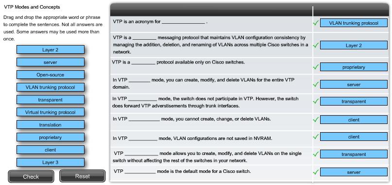
23 VTP Modes Overview Server Mode In server mode, you can create, modify, and delete VLANs for the entire VTP domain. Client Mode VTP server mode is the default mode for a Cisco switch. VTP servers advertise their VLAN configurations to other switches in the same VTP domain and synchronize their VLAN configurations with other switches based on advertisements received over trunk links. VTP servers track of updates through a configuration revision number. Other switches in the same VTP domain compare their configuration revision to see if they need to synchronize their VLAN database. If a switch is in client mode, you cannot create, change, or delete VLANs. The VLAN configuration information that a VTP client switch receives from a VTP server switch is stored in a VLAN database, not in NVRAM. When a VTP client is shut down and restarted, it sends a request advertisement to a VTP server for updated VLAN information. Transparent Mode Switches configured in transparent mode forward VTP advertisements that they receive on trunk ports to other switches. VTP transparent mode switches do not advertise their VLAN and do not synchronize their VLAN configuration with other switch. A VTP transparent mode switch reboots, it does not revert to a default VTP server mode, but remains in VTP transparent mode. 23


24 1 VTP in Action You will now see how the various VTP features come together to distribute and synchronize domain and VLAN configurations in a VTP-enabled network. The animation starts with three new switches, S1, S2, and S3, configured with their factory default settings, and finishes with all three switches configured and participating in a VTP-enabled network


25 VTP in Action: VTP transparent mode Continued from the previous slide You have seen how VTP works with three switches. This animation examines in more detail how a switch configured in VTP transparent mode supports the functionality of VTP


26 VTP pruning VTP pruning prevents unnecessary flooding of broadcast information from one VLAN across all trunks in a VTP domain. VTP pruning permits switches to negotiate which VLANs are assigned to ports at the other end of a trunk and, hence, prune the VLANs that are not assigned to ports on the remote switch. Pruning is disabled by default. VTP pruning is enabled using the vtp pruning global configuration command. You need to enable pruning on only one VTP server switch in the domain. In the figure, you would enable VTP pruning on switch S1. Switch S3 has VLAN 20 configured, Switch S2 has VLAN 10 and VLAN 20 configured. 26


27 VTP Pruning in Action VTP Pruning in Action A VLAN creates an isolated broadcast domain. A switch floods broadcast, multicast, and unknown unicast traffic across all trunk links within a VTP domain. When a computer or device broadcasts on a VLAN, for example, VLAN 10 in the figure, the broadcast traffic travels across all trunk links throughout the network to all ports on all switches in VLAN 10. In the figure, switches S1, S2, and S3 all receive broadcast frames from computer PC1. The link between switches S1 and S3 does not carry any VLAN 10 traffic, so it is a candidate for VTP pruning. VTP Pruning The flood traffic is stopped from entering the trunk connecting switches S1 and S2. VTP pruning only prunes the egress port F0/1 on switch S2. 27


28 VTP Pruning Enabled The figure shows a network topology that has switches S1, S2, and S3 configured with VTP pruning. When VTP pruning is enabled on a network, it reconfigures the trunk links based on which ports are configured with which VLANs. VTP pruning only prunes the egress port. The highlighted area shows that the trunk on port F0/1 allows VLAN 10 traffic. The highlighted area shows that the trunk on port F0/1 does not allow VLAN 10 traffic. VLAN 10 is not listed. 28


29 VTP Pruning Increases available bandwidth by reducing unnecessary flooded traffic forwarding broadcasts and unknown unicast frames on a VLAN over trunk links only if the receiving end of the trunk has ports in that VLAN. The broadcast problem in VLAN A host connected to a port configured for VLAN 2 on Switch 1, generates a network broadcast. Switch will forward the broadcast out its trunk link, so it may reach all ports in the network. The Root switch receives the broadcast through one of it's trunks and immediately forwards it out the other two - towards Switch 2 & 3. Enabling VTP Pruning VTP Pruning solves the above problem by reducing the unnecessary flooded traffic described previously. This is done by forwarding broadcasts and unknown unicast frames on a VLAN over trunk links only if the receiving end of the trunk has ports in that VLAN
 5 3, 4 1 1, 3")
30 VTP Pruning Enabled TestLet (S2 is replaced by S3) 5 3, 4 1 1, 3 30


31 Example of VTP in action VTP Modes Server will accept new vlan ceation default VTP mode, but VLANs are not propagated over the network until a management domain name is specified or learned Create vlans Modify vlans Delete vlans Sends/forwards advertisements Synchronize Saved in NVRAM Client will not accept new vlan ceation Forwards advertisements Synchronize Not saved in NVRAM Not Create vlans Not Modify vlans Not Delete vlans Transparent Create vlans Modify vlans Delete vlans Forwards advertisements Does not synchronize Saved in NVRAM changes are not transmitted to other switches in the domain, and they affect only the individual switch Local copy

32 How VTP Works VTP Server Mode By default all switches are configured as VTP Servers when first powered on. All VLAN information such as VLAN number and VLAN name is stored locally, on a separate NVRAM from where the 'startup-config' is stored, ie, vlan.dat 32 32


33 How VTP Works VTP Client Mode In most networks, the clients connect directly to the VTP Server as shown in our previous diagram. If, for any reason, two clients are cascaded together, then the information will propagate downwards via the available Trunk links, ensuring it reaches all switches. If the link between the cascaded 2950's was not a trunk link but an access link, then the 2nd set of switches would not receive and VTP updates

34 How VTP Works VTP Transparent Mode A Transparent VTP switch will act as a VTP relay (forward all VTP information it receives, out its trunk ports) only when VTP version 2 is used in the network. With VTP version 1, the transparent switch will simply ignore and discard any VTP messages received from the rest of the network
35 VTP Configuration Guidelines VTP Server Switches Confirm that all of switches you are have been set to default settings. Always reset the configuration revision number before installing a previously configured switch into a VTP domain. Not resetting the configuration revision number allows for potential disruption in the VLAN configuration across the rest of the switches. Configure at least two VTP server switches in your network. In case the primary VTP server becomes disabled, if all the switches are in VTP client mode, you cannot create new VLANs on the network. Configure a VTP domain on the VTP server. Other switches connected through trunk links receive the VTP domain information automatically through VTP advertisements. If there is an existing VTP domain, make sure that you match the name exactly. VTP domain names are case-sensitive. If you are configuring a VTP password, ensure that the same password is set on all switches in the domain. Switches without password or with the wrong password reject VTP advertisements. Ensure that all switches are configured to use the same VTP version. VTP version 1 is not compatible with VTP version 2. By default, Cisco Catalyst 2960 switches run version 1 but are capable of running version 2. Create the VLAN after you have enabled VTP on the VTP server. VTP information is only exchanged on trunk ports. 35
36 VTP Configuration Guidelines VTP Client Switches As on the VTP server switch, confirm that the default settings are present. Configure VTP client mode. Switch is not in VTP client mode by default. You have to configure this mode. Configure trunks. VTP works over trunk links. Connect to a VTP server. When you connect to a VTP server or another VTP-enabled switch, it takes a few moments for the various advertisements to make their way back and forth to the VTP server. Verify VTP status. Before you begin configuring the access ports, confirm that the revision mode and number of VLANs have been updated. Configure access ports. When a switch is in VTP client mode, you cannot add new VLANs. You can only assign access ports to existing VLANs. 36


37 Configuring VTP: Step 1 Configure the VTP Server Initially none of the devices are connected. The topology highlights switch S1. You will configure this switch to be a VTP server. The output of the show vtp status command confirms that the switch is by default a VTP server. the revision number is still set to 0 the switch does not belong to VTP domain. Configure the VTP Server If the switch was not already configured as a VTP server, you could configure it using the the vtp mode {server} command. The domain name is configured using the the vtp domaindomain-name command. switch S1 has been configured with the domain name cisco1. For security reasons, a password could be configured using the vtp passwordpassword command. The default version for Catalyst 2960 is version 1. Assume that three VLANs have been configured and have been assigned VLANs names. 37


38 Configuring VTP: Step 2 Configure the VTP client The topology highlights switches S2 and S3. You will be shown the VTP client configuration for S2. To configure S3 as a VTP client, you will follow the same procedure. Configure the VTP Client Before configuring a switch as a VTP client, verify its current VTP status. Show vtp status Configure VTP client mode using the following Cisco IOS command syntax: Enter global configuration mode with the configure terminal command. Configure the switch in client mode with the vtp mode {client} command. 38


39 Configuring VTP: Step 3 Confirm and Connect After configuring the main VTP server and the VTP clients, you will connect the VTP client switch S2 to the switch S1 VTP server. The topology highlights the trunks that will be added to this topology. Confirm VTP Operation There are 2 commands for confirming that VTP domain and VLAN configurations have been transferred. Use show VTP status command to verify the following: Configuration revision number has been incremented to 6. There are now three new VLANs indicated by the existing number of VLANs showing 8. Domain name has been changed to cisco1. Use show vtp counters command to confirm that the advertisements took place. Configure Access Ports The task now is to configure the port F0/11 on switch S2 to be in VLAN 20. Use the switchport access vlan [number] interface command 39
40 * See VTP in action between 2 switches Catalyst 2900 server Catalyst 3550 client VLANs are consistent between server and client Client try to assign a port to a not exist vlan Client failed to create vlan 55 and port 0/3 disappeared
41 * See VTP in action between 2 switches Create vlan 55 on the server vlan 55 propagated to client and port 0/3 can be used now Vtp revision number also incremented by 1 Add another vlan to the server Newly created vlan 62 automatically propagated to the client, even there is no port assign to the vlan 41 41
42 Troubleshooting VTP Connections In this topic, you will learn about common VTP configuration problems. This information, combined with your VTP configuration skills, will help you when troubleshooting VTP configuration problems. 42
43 Troubleshooting VTP: Incompatible VTP Versions VTP versions 1 and 2 are incompatible with each other. Modern Cisco Catalyst switches, such as the 2960, are configured to use VTP version 1 by default. However, older switches may only support VTP version 1. Switches that only support version 1 cannot participate in the VTP domain along with version 2 switches. If your network contains switches that support only version 1, you need to manually configure the version 2 switches to operate in version 1 mode. 43

44 Troubleshooting VTP: VTP Password Issues When using a VTP password to control participation in the VTP domain, ensure that the password is set correctly on all switches in the VTP domain. Forgetting to set a VTP password is a very common problem. If a password is used, it must be configured on each switch in the domain. By default, a Cisco switch does not use a VTP password. The switch does not automatically set the password parameter, unlike other parameters that are set automatically when a VTP advertisement is received. 44


45 Troubleshooting VTP: Incorrect VTP Domain Name The VTP domain name is a key parameter that is set on a switch. Solution An improperly configured VTP domain affects VLAN synchronization between switches. As you learned earlier, if a switch receives the wrong VTP advertisement, the switch discards the message. To avoid incorrectly configuring a VTP domain name, only set the VTP domain name on one VTP server switch. All other switches in the same VTP domain will accept and automatically configure their VTP domain name when they receive the first VTP summary advertisement. 45


46 Troubleshooting VTP: Switches Set to VTP Client Mode It is possible to change the operating mode of all switches to VTP client. Solution By doing so, you lose all ability to create, delete, and manage VLANs within your network environment. To avoid losing all VLAN configurations in a VTP domain by accidentally reconfiguring the only VTP server in the domain as a VTP client, you can configure a second switch in the same domain as a VTP server. It is not uncommon for small networks that use VTP to have all the switches in VTP server mode. 46


47 Troubleshooting VTP: Incorrect Revision Number The topology in the figure is configured with VTP. There is one VTP server switch, S1, and two VTP client switches, S2 and S3. S4, which has been previously configured as a VTP client, is added to the network. The revision number of the switch S4 is 35, which is higher than the revision number of 17 in the existing network. S4 comes preconfigured with two VLANs, 30 and 40, that are not configured in the existing network. The existing network has VLANs 10 and 20. When switch S4 is connected to switch S3, VTP summary advertisements announce the arrival of a VTP-enabled switch with the highest revision number in the network. The figure shows how switch S3, switch S1, and finally switch S2 all reconfigure themselves to the configuration found in switch S4. As each switch reconfigures itself with VLANs that are not supported in the network, the ports no longer forward traffic from the computers because they are configured with VLANs that no longer exist on the newly reconfigured switches. 47


48 Troubleshooting VTP: Incorrect Revision Number Solution The solution to the problem is to reset each switch back to an earlier configuration and then reconfigure the correct VLANs, 10 and 20, on switch S1. To prevent this problem in the first place, reset the configuration revision number on previously configured switches being added to a VTPenabled network. The figure shows the commands needed to reset switch S4 back to the default revision number. POP QUIZ: How about just power cycle the switch 4 and rest the revision number before plug it into the network? Make sure you understand the message about this revision number issue. The vlan/vtp synchronization can be triggered by the client as well. 48
49 Troubleshooting VTP: Incorrect Revision Number POP QUIZ: Is it possible for a switch network with switches that have the same revision number, but with different VLAN information and different numbers of VLANs? 49


50 Managing VLANs on a VTP Server When a new VLAN, for example, VLAN 10, is added to the network, the network manager adds the VLAN to the VTP server, switch S1 in the figure. As you know, VTP takes care of propagating the VLAN configuration details to the rest of the network. It does not have any effect on which ports are configured in VLAN 10 on switches S1, S2, and S3. The figure displays the commands used to configure VLAN 10 and the port F0/11 on switch S1. After you have configured the new VLAN on switch S1 and configured the ports on switches S1, S2, and S3 to support the new VLAN, confirm that VTP updated the VLAN database on switches S2 and S3. The output of the command is used to verify the configuration on switch S2. The output confirms that the new VLAN has been added to F0/1 on switch S2. The highlighted area shows that VLAN 10 is now active in the VTP management domain. 50
51 Summary VTP is a Cisco proprietary protocol used to exchange VLAN information across trunk links. A switch can be in one of 3 VTP operating modes Client Cannot create, modify or delete VLAN Server Can create, modify & delete VLAN Transparent Can create, modify, & delete LOCAL VLAN Forwards VTP advertisements. 51
52 Summary VTP pruning Limits unnecessary Tony Chen COD dissemination of VLAN information. Cisco Networking Academy Verify VTP configuration Show VTP status Show interfaces trunk 52
Configuring VTP. Understanding How VTP Works CHAPTER
 CHAPTER 13 This chapter describes how to configure the VLAN Trunking Protocol (VTP) on the Cisco 7600 series routers. For complete syntax and usage information for the commands used in this chapter, refer
Configuring VTP. Understanding VTP CHAPTER
 CHAPTER 14 This chapter describes how to use the VLAN Trunking Protocol (VTP) and the VLAN database for managing VLANs with the Catalyst 3750 switch. Unless otherwise noted, the term switch refers to a
Configuring VTP. Understanding VTP CHAPTER
 CHAPTER 15 This chapter describes how to use the VLAN Trunking Protocol (VTP) and the VLAN database for managing VLANs with the Catalyst 3560 switch. For complete syntax and usage information for the commands
Understanding and Configuring VTP
 27 CHAPTER This chapter describes the VLAN Trunking Protocol (VTP) on the Catalyst 4500 series switch. It also provides guidelines, procedures, and configuration examples. This chapter includes the following
For information about configuring these settings from Cluster Management Suite (CMS), refer to the online help.
, refer to the online help.") Configuring VLANs This chapter provides information about configuring virtual LANs (VLANs). It includes command-line interface (CLI) procedures for using commands that have been specifically created or
Configuring VLANs This chapter provides information about configuring virtual LANs (VLANs). It includes command-line interface (CLI) procedures for using commands that have been specifically created or
Configuring VLANs. Understanding VLANs CHAPTER
 CHAPTER 11 This chapter describes how to configure normal-range VLANs (VLAN IDs 1 to 1005) and extended-range VLANs (VLAN IDs 1006 to 4094) on your Catalyst 3550 switch. It includes information about VLAN
Configuring VLANs. Understanding VLANs CHAPTER
 CHAPTER 14 This chapter describes how to configure normal-range VLANs (VLAN IDs 1 to 1005) and extended-range VLANs (VLAN IDs 1006 to 4094). It includes information about VLAN modes and the VLAN Membership
Configuring VLANs. Understanding VLANs CHAPTER
 CHAPTER 10 This chapter describes how to configure normal-range VLANs (VLAN IDs 1 to 1005) and extended-range VLANs (VLAN IDs 1006 to 4094) on the switch. It includes information about VLAN membership
Configuring VLANs. Understanding VLANs CHAPTER
 CHAPTER 16 This chapter describes how to configure normal-range VLANs (VLAN IDs 1 to 1005) and extended-range VLANs (VLAN IDs 1006 to 4094) on your Catalyst 2950 or Catalyst 2955 switch. It includes information
Configuring VTP. Understanding How VTP Version 1 and Version 2 Work CHAPTER
 10 CHAPTER This chapter describes how to configure the VLAN Trunking Protocol (VTP) on the Catalyst 6500 series switches For complete syntax and usage information for the commands that are used in this
Configuring VLANs. Understanding VLANs CHAPTER
 CHAPTER 12 This chapter describes how to configure normal-range VLANs (VLAN IDs 1 to 1005) and extended-range VLANs (VLAN IDs 1006 to 4094) on the switch. It includes information about VLAN membership
Configuring VLANs. Understanding VLANs CHAPTER
 CHAPTER 9 This chapter describes how to configure normal-range VLANs (VLAN IDs 1 to 1005) and extended-range VLANs (VLAN IDs 1006 to 4094). It includes information about VLAN membership modes, VLAN configuration
Configuring VLANs. Understanding VLANs CHAPTER
 CHAPTER 14 This chapter describes how to configure normal-range VLANs (VLAN IDs 1 to 1005) and extended-range VLANs (VLAN IDs 1006 to 4094) on the Catalyst 3750 switch. It includes information about VLAN
Implement Inter-VLAN Routing. LAN Switching and Wireless Chapter 6 Modified by Tony Chen 11/01/2008
 Implement Inter-VLAN Routing LAN Switching and Wireless Chapter 6 Modified by Tony Chen 11/01/2008 ITE I Chapter 6 2006 Cisco Systems, Inc. All rights reserved. Cisco Public 1 Notes: If you see any mistake
VLAN Trunking Protocol (VTP)
") 24 CHAPTER Prerequisites for VTP, page 24-1 Restrictions for VTP, page 24-1 Information About VTP, page 24-2 Default Settings for VTP, page 24-9 How to Configure VTP, page 24-10 For complete syntax and
24 CHAPTER Prerequisites for VTP, page 24-1 Restrictions for VTP, page 24-1 Information About VTP, page 24-2 Default Settings for VTP, page 24-9 How to Configure VTP, page 24-10 For complete syntax and
Token Ring VLANs and Related Protocols
 Token Ring VLANs and Related Protocols CHAPTER 4 Token Ring VLANs A VLAN is a logical group of LAN segments, independent of physical location, with a common set of requirements. For example, several end
Maintaining Specific VLAN Identification. Comparing ISL and 802.1Q. VLAN Trunking
 Maintaining Specific VLAN Identification Specifically developed for multi-vlan interswitch communications Places a unique identifier in each frame Functions at Layer 2 2003, Cisco Systems, Inc. All rights
Lab Catalyst 2950T and 3550 Series VTP Domain and VLAN Trunking
 Lab 2.9.2 Catalyst 2950T and 3550 Series VTP Domain and VLAN Trunking Objective Configure a VLAN trunk between two Cisco Catalyst WS-C2950T-24-EI switches and a Cisco Catalyst WS-C3550-24-EMI switch in
Configuring VLANs. Understanding VLANs CHAPTER
 7 CHAPTER This chapter describes how to configure normal-range VLANs (VLAN IDs 1 to 1005) and extended-range VLANs (VLAN IDs 1006 to 4094) on the Cisco MWR 2941 router. It includes information about VLAN
Configuring VLANs. Finding Feature Information. Prerequisites for VLANs
 Finding Feature Information, page 1 Prerequisites for VLANs, page 1 Restrictions for VLANs, page 2 Information About VLANs, page 2 How to Configure VLANs, page 7 Monitoring VLANs, page 19 Where to Go Next,
Configuring VLAN Trunk Protocol (VTP)
") Configuring VLAN Trunk Protocol (VTP) Document ID: 98154 Contents Introduction Prerequisites Requirements Components Used Conventions Understand VTP VTP Configuration Guidelines VTP Configuration on Catalyst
Configuring VLAN Trunk Protocol (VTP) Document ID: 98154 Contents Introduction Prerequisites Requirements Components Used Conventions Understand VTP VTP Configuration Guidelines VTP Configuration on Catalyst
Configuring VLANs. Understanding VLANs CHAPTER
 CHAPTER 11 This chapter describes how to configure normal-range VLANs (VLAN IDs 1 to 1005) and extended-range VLANs (VLAN IDs 1006 to 4094) on the Cisco ME 3400 Ethernet Access switch. It includes information
Lab Catalyst 2950T and 3550 Series VTP Domain and VLAN Trunking
 Lab 2.3.7.1 Catalyst 2950T and 3550 Series VTP Domain and VLAN Trunking Objective Configure a VLAN trunk between two Cisco Catalyst WS-C2950T-24-EI switches and a Cisco Catalyst WS-C3550-24-EMI switch
VLANs. Traditional Campus Networks. Performance Issues. Broadcast Issues. Bridges terminate collision domains
 Traditional Campus Networks Broadcast Domain VLANs Collision Domain 1 Collision Domain 2 Bridges terminate collision domains 2003, Cisco Systems, Inc. All rights reserved. 2-1 2003, Cisco Systems, Inc.
VLANs. 2003, Cisco Systems, Inc. All rights reserved. 2-1
 VLANs 2003, Cisco Systems, Inc. All rights reserved. 2-1 Traditional Campus Networks Broadcast Domain Collision Domain 1 Collision Domain 2 Bridges terminate collision domains 2003, Cisco Systems, Inc.
VLANs. 2003, Cisco Systems, Inc. All rights reserved. 2-1
 VLANs 2003, Cisco Systems, Inc. All rights reserved. 2-1 Traditional Campus Networks Broadcast Domain Collision Domain 1 Collision Domain 2 Bridges terminate collision domains 2003, Cisco Systems, Inc.
Token Ring VLANs and Related Protocols
 CHAPTER 4 Token Ring VLANs and Related Protocols A VLAN is a logical group of LAN segments, independent of physical location, with a common set of requirements. For example, several end stations might
Upon completion of this chapter, you will be able to perform the following tasks: Identify what a VLAN is and how it operates. Configure a VLAN to
 Upon completion of this chapter, you will be able to perform the following tasks: Identify what a VLAN is and how it operates. Configure a VLAN to improve network performance. Identify what role the switch
VLAN Configuration. Understanding VLANs CHAPTER
 CHAPTER 11 This chapter describes how to configure normal-range VLANs (VLAN IDs 1 to 1005) and extended-range VLANs (VLAN IDs 1006 to 4094) on the CGR 2010 ESM. It includes information about VLAN membership
Switches running the LAN Base feature set support only static routing on SVIs.
 Finding Feature Information, on page 1 Prerequisites for VLANs, on page 1 Restrictions for VLANs, on page 2 Information About VLANs, on page 2 How to Configure VLANs, on page 6 Monitoring VLANs, on page
Configuring VLANs. Finding Feature Information. Prerequisites for VLANs
 Finding Feature Information, page 1 Prerequisites for VLANs, page 1 Restrictions for VLANs, page 2 Information About VLANs, page 2 How to Configure VLANs, page 8 Monitoring VLANs, page 22 Where to Go Next,
Table of Contents. Cisco Understanding and Configuring VLAN Trunk Protocol (VTP)
") Table of Contents Understanding and Configuring VLAN Trunk Protocol (VTP)...1 Document ID: 10558...1 Interactive: This document offers customized analysis of your Cisco device...1 This document contains
Table of Contents Understanding and Configuring VLAN Trunk Protocol (VTP)...1 Document ID: 10558...1 Interactive: This document offers customized analysis of your Cisco device...1 This document contains
Chapter 2 Lab 2-1, Static VLANS, VLAN Trunking, and VTP Domains and Modes
 Chapter 2 Lab 2-1, Static VLANS, VLAN Trunking, and VTP Domains and Modes Topology Objectives Background Set up a VTP domain. Create and maintain VLANs. Configure ISL and 802.1Q trunking. VLANs logically
Extending Switched Networks with Virtual LANs. 2000, Cisco Systems, Inc. 7-1
 Extending Switched Networks with Virtual LANs 2000, Cisco Systems, Inc. 7-1 Objectives Upon completion of this chapter, you will be able to perform the following tasks: Configure a VLAN Configure VLAN
Chapter 3: VLANs. Routing & Switching
 Chapter 3: VLANs Routing & Switching VLAN Definitions A VLAN is a logical partition of a Layer 2 network. VLANs logically group hosts, regardless of physical location. Multiple partitions can be created,
Note: Use two 2960 switches for ALS1 and ALS2 and two 3560 switches for DLS1 and DLS2
 LAB 2 - Part I - VLANs, VLAN Trunking, and VTP Domains Topology: Objectives Set up a VTP domain. Create and maintain VLANs. Configure 802.1Q trunking. Background VLANs logically segment a network by function,
Ch. 9 VTP (Trunking, VTP, Inter-VLAN Routing) CCNA 3 version 3.0
 CCNA 3 version 3.0") Ch. 9 VTP (Trunking, VTP, Inter-VLAN Routing) CCNA 3 version 3.0 Overview Explain the origins and functions of VLAN trunking Describe how trunking enables the implementation of VLANs in a large network
Ch. 9 VTP (Trunking, VTP, Inter-VLAN Routing) CCNA 3 version 3.0 Overview Explain the origins and functions of VLAN trunking Describe how trunking enables the implementation of VLANs in a large network
CHAPTER 1: VLANS. Routing & Switching
 CHAPTER 1: VLANS Routing & Switching CHAPTER 1 1.1 VLAN Segmentation 1.2 VLAN Implementation 1.3 VLAN Security and Design 1.4 Summary CHAPTER 1 : OBJECTIVES Explain the purpose of VLANs in a switched network.
isco Understanding and Configuring VLAN Trunk Protocol (V
 isco Understanding and Configuring VLAN Trunk Protocol (V Table of Contents Understanding and Configuring VLAN Trunk Protocol (VTP)...1 Contents...1 Introduction...1 Understanding VTP...2 VTP Domain Name...2
Lab Catalyst 2950T and 3550 Series VTP Pruning
 Lab 2.9.3 Catalyst 2950T and 3550 Series VTP Pruning Objective Configure VTP pruning between two Cisco Catalyst WS-C2950T-24-EI switches and a Cisco Catalyst WS-C3550-24-EMI switch using the command-line
VLANs and Trunking C H A P T E R. 6-1: VLAN Configuration. Section 6-1
 C H A P T E R 6 Section 6-1 VLANs and Trunking See the following sections for configuration information about these topics: 6-1: VLAN Configuration Describes the method for configuring, creating, and configuring
Configuring Port-Based Traffic Control
 CHAPTER 18 This chapter describes how to configure port-based traffic control features on the Catalyst 3750 Metro switch. For complete syntax and usage information for the commands used in this chapter,
Lab Catalyst 2950T and 3550 Series VTP Pruning
 Lab 2.3.7.2 Catalyst 2950T and 3550 Series VTP Pruning Objective Configure VTP pruning between two Cisco Catalyst WS-C2950T-24-EI switches and a Cisco Catalyst WS-C3550-24-EMI switch using the command-line
Implement Spanning Tree Protocols-PART-I. LAN Switching and Wireless Chapter 5 Modified by Tony Chen 05/01/2008
 Implement Spanning Tree Protocols-PART-I LAN Switching and Wireless Chapter 5 Modified by Tony Chen 05/01/2008 ITE I Chapter 6 2006 Cisco Systems, Inc. All rights reserved. Cisco Public 1 Notes: If you
PASS4TEST IT 인증시험덤프전문사이트
 PASS4TEST IT 인증시험덤프전문사이트 http://www.pass4test.net 일년동안무료업데이트 Exam : 640-802 Title : Cisco Certified Network Associate(CCNA) Vendors : Cisco Version : DEMO 1 / 10 Get Latest & Valid 640-802 Exam's Question
Configuring STP. Understanding Spanning-Tree Features CHAPTER
 CHAPTER 11 This chapter describes how to configure the Spanning Tree Protocol (STP) on your switch. For information about the Rapid Spanning Tree Protocol (RSTP) and the Multiple Spanning Tree Protocol
Configuring Port-Based Traffic Control
 Overview of Port-Based Traffic Control, page 1 Finding Feature Information, page 2 Information About Storm Control, page 2 How to Configure Storm Control, page 4 Information About Protected Ports, page
The multiple spanning-tree (MST) implementation is based on the IEEE 802.1s standard.
 implementation is based on the IEEE 802.1s standard.") CHAPTER 18 This chapter describes how to configure the Cisco implementation of the IEEE 802.1s Multiple STP (MSTP) on the IE 3010 switch. Note The multiple spanning-tree (MST) implementation is based on
CHAPTER 18 This chapter describes how to configure the Cisco implementation of the IEEE 802.1s Multiple STP (MSTP) on the IE 3010 switch. Note The multiple spanning-tree (MST) implementation is based on
Configuring Port-Based Traffic Control
 CHAPTER 22 This chapter describes how to configure the port-based traffic control features on the Cisco ME 3400 Ethernet Access switch. For complete syntax and usage information for the commands used in
Cisco Exploration 3 Module 3 LAN Switching and Wireless Jim Johnston Class Notes September 9, 2008
 Cisco Exploration 3 Module 3 LAN Switching and Wireless Jim Johnston Class Notes September 9, 2008 VLAN is a logically separate IP subnetwork. This allows multiple networks to exist on a switch and provide
Configuring VTP V3. Configuring VTP V3. VTP V3 Overview. Guidelines and Limitation. This chapter contains the following sections:
 This chapter contains the following sections:, page 1 From Cisco NX-OS Release 7.2(0)N1(1), VLAN Trunk Protocol (VTP) V3 supports PVLAN integration, 4K VLAN integration, generic database transport mechanism,
Configuring Private VLANs
 CHAPTER 15 This chapter describes how to configure private VLANs on the Cisco 7600 series routers. Note For complete syntax and usage information for the commands used in this chapter, refer to the Cisco
Internetwork Expert s CCNP Bootcamp. VLANs, Trunking, & VTP. VLANs Overview
 Internetwork Expert s CCNP Bootcamp VLANs, Trunking, & VTP http:// VLANs Overview Virtual Local Area Network Hosts in the same VLAN share the same broadcast domain Switches create a separate CAM table
All Transparent VTP Domain to Server Client VTP Domain Migration Configuration Example
 All Transparent VTP Domain to Server Client VTP Domain Migration Configuration Example Document ID: 81682 Contents Introduction Prerequisites Requirements Components Used Conventions Background Information
Configuring Spanning Tree Protocol
 Restrictions for STP Restrictions for STP, on page 1 Information About Spanning Tree Protocol, on page 1 How to Configure Spanning-Tree Features, on page 13 Monitoring Spanning-Tree Status, on page 25
Configuring Port-Based Traffic Control
 Overview of Port-Based Traffic Control, page 2 Finding Feature Information, page 2 Information About Storm Control, page 2 How to Configure Storm Control, page 4 Finding Feature Information, page 9 Information
Configuring Private VLANs
 36 CHAPTER This chapter describes private VLANs (PVLANs) on Catalyst 4500 series switches. It also provides restrictions, procedures, and configuration examples. This chapter includes the following major
Exam Implementing Cisco IP Switched Networks (SWITCH)
") Cisco Certified Network Professional (CCNP) Exam 300-115 Implementing Cisco IP Switched Networks (SWITCH) Multiple Choice Questions (2018-05-08 Updated) (300-115) Implementing Cisco IP Switched Networks
Cisco Certified Network Professional (CCNP) Exam 300-115 Implementing Cisco IP Switched Networks (SWITCH) Multiple Choice Questions (2018-05-08 Updated) (300-115) Implementing Cisco IP Switched Networks
Configuring IP Multicast Routing
 39 CHAPTER This chapter describes how to configure IP multicast routing on the Catalyst 3560 switch. IP multicasting is a more efficient way to use network resources, especially for bandwidth-intensive
Configuring Rapid PVST+
 This chapter describes how to configure the Rapid per VLAN Spanning Tree (Rapid PVST+) protocol on Cisco NX-OS devices using Cisco Data Center Manager (DCNM) for LAN. For more information about the Cisco
Configuring IP Multicast Routing
 34 CHAPTER This chapter describes how to configure IP multicast routing on the Cisco ME 3400 Ethernet Access switch. IP multicasting is a more efficient way to use network resources, especially for bandwidth-intensive
Configuring EtherChannels and Link-State Tracking
 CHAPTER 37 Configuring EtherChannels and Link-State Tracking This chapter describes how to configure EtherChannels on Layer 2 and Layer 3 ports on the switch. EtherChannel provides fault-tolerant high-speed
Configuring Spanning Tree Protocol
 Finding Feature Information, page 1 Restrictions for STP, page 1 Information About Spanning Tree Protocol, page 2 How to Configure Spanning-Tree Features, page 14 Monitoring Spanning-Tree Status, page
2.2 Cisco IOS Commands for the Catalyst 4500 Series Switches snmp ifindex clear. This command has no arguments or keywords.
 Chapter 2 2.2 snmp ifindex clear snmp ifindex clear To clear any previously configured snmp ifindex commands that were entered for a specific interface, use the snmp ifindex clear command. snmp ifindex
Configuring SPAN and RSPAN
 Finding Feature Information, page 1 Prerequisites for SPAN and RSPAN, page 1 Restrictions for SPAN and RSPAN, page 2 Information About SPAN and RSPAN, page 3 How to Configure SPAN and RSPAN, page 14 Monitoring
LAN Troubleshooting. Ethernet Troubleshooting
 CCIE Routing & Switching Advanced Troubleshooting Bootcamp LAN Troubleshooting http:// Ethernet Troubleshooting No Ethernet switching troubleshooting in Troubleshooting Section, but it can be included
Lab 5: Inter-VLANs Routing
 Lab 5: Inter-VLANs Routing Network Topology:- Device Interface IP Address Subnet Mask Gateway/Clock Rate Fa 0/0.10 10.5.0.1 255.255.255.192 ----- R1 Fa 0/0.20 10.6.0.1 255.255.255.192 ----- Fa 0/0.30 10.10.0.1
Configuring Rapid PVST+ Using NX-OS
 Configuring Rapid PVST+ Using NX-OS This chapter describes how to configure the Rapid per VLAN Spanning Tree (Rapid PVST+) protocol on Cisco NX-OS devices. This chapter includes the following sections:
Configuring STP and RSTP
 7 CHAPTER Configuring STP and RSTP This chapter describes the IEEE 802.1D Spanning Tree Protocol (STP) and the ML-Series implementation of the IEEE 802.1W Rapid Spanning Tree Protocol (RSTP). It also explains
1. Which two statements are true about VLAN implementation? (Choose two.)
") CCNA 2 Chapter 3 v5.0 Exam Answers 2015 (100%) 1. Which two statements are true about VLAN implementation? (Choose two.) The size of the collision domain is reduced. The number of required switches in
CCNA 2 Chapter 3 v5.0 Exam Answers 2015 (100%) 1. Which two statements are true about VLAN implementation? (Choose two.) The size of the collision domain is reduced. The number of required switches in
Top-Down Network Design
 Top-Down Network Design Chapter Seven Selecting Switching and Routing Protocols Original slides by Cisco Press & Priscilla Oppenheimer Selection Criteria for Switching and Routing Protocols Network traffic
2rd2 Cisco IOS Commands for the Cisco 7600 Series Router verify. verify {{{/md5 flash-filesystem} [expected-md5-signature]} {/ios flash-filesystem}
![2rd2 Cisco IOS Commands for the Cisco 7600 Series Router verify. verify {{{/md5 flash-filesystem} [expected-md5-signature]} {/ios flash-filesystem}](/thumbs/72/67723196.jpg "2rd2 Cisco IOS Commands for the Cisco 7600 Series Router verify. verify {{{/md5 flash-filesystem} [expected-md5-signature]} {/ios flash-filesystem}") Chapter 2 2rd2 verify verify To verify the checksum of a file on a Flash memory file system or compute an MD5 signature for a file, use the verify command. verify {{{/md5 flash-filesystem} [expected-md5-signature]}
Chapter 2 2rd2 verify verify To verify the checksum of a file on a Flash memory file system or compute an MD5 signature for a file, use the verify command. verify {{{/md5 flash-filesystem} [expected-md5-signature]}
VLAN. Command Reference, Cisco IOS XE Everest 16.6.x (Catalyst 3850 Switches) 1
 1") clear vtp counters, page 2 debug platform vlan, page 3 debug sw-vlan, page 4 debug sw-vlan ifs, page 6 debug sw-vlan notification, page 7 debug sw-vlan vtp, page 9 interface vlan, page 11 private-vlan,
clear vtp counters, page 2 debug platform vlan, page 3 debug sw-vlan, page 4 debug sw-vlan ifs, page 6 debug sw-vlan notification, page 7 debug sw-vlan vtp, page 9 interface vlan, page 11 private-vlan,
Chapter 2. Switch Concepts and Configuration. Part I
 Chapter 2 Switch Concepts and Configuration Part I CCNA3-1 Chapter 2-1 Note for Instructors These presentations are the result of a collaboration among the instructors at St. Clair College in Windsor,
no udld {aggressive enable message time seconds}
 udld udld To enable aggressive or normal mode in UniDirectional Link Detection protocol (UDLD) and set the configurable message time, use the udld command in global configuration mode. To disable aggressive
Configuring Rapid PVST+
 This chapter contains the following sections: Information About Rapid PVST+, page 1, page 16 Verifying the Rapid PVST+ Configuration, page 24 Information About Rapid PVST+ The Rapid PVST+ protocol is the
Lab - Troubleshooting VLAN Configurations (Instructor Version Optional Lab)
") (Instructor Version Optional Lab) Instructor Note: Red font color or gray highlights indicate text that appears in the instructor copy only. Optional activities are designed to enhance understanding and/or
(Instructor Version Optional Lab) Instructor Note: Red font color or gray highlights indicate text that appears in the instructor copy only. Optional activities are designed to enhance understanding and/or
Configuring the Catalyst 3920
 CHAPTER 5 Configuring the Catalyst 3920 You might not have to configure the Catalyst 3920 for it to work in your network; it is shipped with default configuration parameters and can function with these
Chapter 3. Virtual Local Area Networks (VLANs) Part II
 Part II") Chapter 3 Virtual Local Area Networks (VLANs) Part II CCNA3-1 Chapter 3-2 Note for Instructors These presentations are the result of a collaboration among the instructors at St. Clair College in Windsor,
Chapter 3 Virtual Local Area Networks (VLANs) Part II CCNA3-1 Chapter 3-2 Note for Instructors These presentations are the result of a collaboration among the instructors at St. Clair College in Windsor,
Campus Networking Workshop. Layer 2 engineering Spanning Tree and VLANs
 Campus Networking Workshop Layer 2 engineering Spanning Tree and VLANs Switching Loop When there is more than one path between two switches What are the potential problems? Switching Loop If there is more
CCNA Cisco Certified Network Associate CCNA (v3.0)
") 200-125 - CCNA Cisco Certified Network Associate CCNA (v3.0) 1.What is one benefit of PVST+? A. PVST+ supports Layer 3 load balancing without loops. B. PVST+ reduces the CPU cycles for all the switches
200-125 - CCNA Cisco Certified Network Associate CCNA (v3.0) 1.What is one benefit of PVST+? A. PVST+ supports Layer 3 load balancing without loops. B. PVST+ reduces the CPU cycles for all the switches
Configuring IEEE 802.1Q Tunneling and Layer 2 Protocol Tunneling
 CHAPTER 14 Configuring IEEE 802.1Q Tunneling and Layer 2 Protocol Tunneling With Release 12.1(13)E and later, the Catalyst 6500 series switches support IEEE 802.1Q tunneling and Layer 2 protocol tunneling.
Configuring EtherChannels and Layer 2 Trunk Failover
 35 CHAPTER Configuring EtherChannels and Layer 2 Trunk Failover This chapter describes how to configure EtherChannels on Layer 2 and Layer 3 ports on the switch. EtherChannel provides fault-tolerant high-speed
Troubleshooting VLAN Trunk Protocol (VTP)
") Troubleshooting VLAN Trunk Protocol (VTP) Document ID: 98155 Contents Introduction Prerequisites Requirements Components Used Conventions Understand VTP Configure VTP VTP Troubleshooting and Caveats Unable
Troubleshooting VLAN Trunk Protocol (VTP) Document ID: 98155 Contents Introduction Prerequisites Requirements Components Used Conventions Understand VTP Configure VTP VTP Troubleshooting and Caveats Unable
Cisco Questions & Answers
 Cisco 200-101 Questions & Answers Number: 200-101 Passing Score: 800 Time Limit: 120 min File Version: 23.7 http://www.gratisexam.com/ Cisco 200-101 Questions & Answers Exam Name: Interconnecting Cisco
Implement Spanning Tree Protocols PART-II. LAN Switching and Wireless Chapter 5 Modified by Tony Chen 07/01/2009
 Implement Spanning Tree Protocols PART-II LAN Switching and Wireless Chapter 5 Modified by Tony Chen 07/01/2009 ITE I Chapter 6 2006 Cisco Systems, Inc. All rights reserved. Cisco Public 1 Notes: If you
Configuring SPAN and RSPAN
 CHAPTER 32 This chapter describes how to configure Switched Port Analyzer (SPAN) and Remote SPAN (RSPAN) on the Catalyst 3750-X or 3560-X switch. Unless otherwise noted, the term switch refers to a Catalyst
Cisco CISCO Interconnecting Cisco Networking Devices Exam (ICND) Practice Test. Version
 Practice Test. Version") Cisco 640-811 CISCO 640-811 Interconnecting Cisco Networking Devices Exam (ICND) Practice Test Version 1.3 QUESTION NO: 1 Cisco 640-811: Practice Exam What is the purpose of the OSPF router ID in a DR/BDR
Cisco 640-811 CISCO 640-811 Interconnecting Cisco Networking Devices Exam (ICND) Practice Test Version 1.3 QUESTION NO: 1 Cisco 640-811: Practice Exam What is the purpose of the OSPF router ID in a DR/BDR
vines access-group vines access-group access-list-number no vines access-group access-list-number Syntax Description
 vines access-group vines access-group To apply an access list to an interface, use the vines access-group command in interface configuration mode. To remove the access list, use the no form of this command.
Configuring VLAN Trunks
 Finding Feature Information, page 1 Prerequisites for VLAN Trunks, page 1 Information About VLAN Trunks, page 2 How to Configure VLAN Trunks, page 5 Configuration Examples for VLAN Trunking, page 20 Where
Using VLAN & Bridge APPENDIX
 APPENDIX I Using VLAN & Bridge The VLAN & Bridge application allows you to configure groups of ports independent of their physical location as a virtual LAN. This arrangement is called a logical grouping
Configuring SPAN and RSPAN
 Prerequisites for SPAN and RSPAN, page 1 Restrictions for SPAN and RSPAN, page 1 Information About SPAN and RSPAN, page 3 How to Configure SPAN and RSPAN, page 14 Monitoring SPAN and RSPAN Operations,
Buy full file at
 14 Chapter 2 LAN Redundancy Chapter 2 LAN Redundancy 2.0.1.2 Class Activity Stormy Traffic ( ) Objective Explain the purpose of the Spanning Tree Protocol (STP) in a switched LAN environment with redundant
Configuring RIP. Information About RIP CHAPTER
 CHAPTER 23 This chapter describes how to configure the ASASM to route data, perform authentication, and redistribute routing information using the Routing Information Protocol (RIP). This chapter includes
This chapter describes how to configure VLANs on the Cisco 7600 series routers.
 CHAPTER 14 This chapter describes how to configure VLANs on the Cisco 7600 series routers. For complete syntax and usage information for the commands used in this chapter, refer to the Cisco 7600 Series
Configuring WCCPv2. Information About WCCPv2. Send document comments to CHAPTER
 CHAPTER 5 This chapter describes how to configure the Web Cache Communication Protocol version 2 (WCCPv2) on Cisco NX-OS devices. This chapter includes the following sections: Information About WCCPv2,
Cisco Implementing Cisco IP Switched Networks (SWITCH v2.0)
") Cisco 300-115 Implementing Cisco IP Switched Networks (SWITCH v2.0) http://killexams.com/pass4sure/exam-detail/300-115 Question: 323 An administrator recently configured all ports for rapid transition
Cisco 300-115 Implementing Cisco IP Switched Networks (SWITCH v2.0) http://killexams.com/pass4sure/exam-detail/300-115 Question: 323 An administrator recently configured all ports for rapid transition
Configuring VLAN CHAPTER
 CHAPTER 10 LMS collects data about devices so that you can configure and manage Virtual Local Area Network (VLAN) in your network. You must set up your LMS server properly to ensure that Data Collection
Cisco IOS Commands for the Catalyst 6500 Series Switches with the Supervisor Engine 32 PISA verify
 Chapter 2 verify verify To verify the checksum of a file on a flash memory file system or compute an MD5 signature for a file, use the verify command. verify {{{/md5 flash-filesystem} [expected-md5-signature]}
Configuring SPAN and RSPAN
 34 CHAPTER This chapter describes how to configure the Switched Port Analyzer (SPAN) and Remote SPAN (RSPAN) on the Catalyst 4500 series switches. SPAN selects network traffic for analysis by a network