Introduction to Switched Networks Routing And Switching
|
|
|
- Augustus Stone
- 6 years ago
- Views:
Transcription

1 Introduction to Switched Networks Routing And Switching 1

2 Converged Networks Growing Complexity of Networks Our digital world is changing Information must be accessed from anywhere in the world Networks must be secure, reliable, and highly available 2
3 Converged Networks Elements Of A Converged Network Collaboration is a requirement To support collaboration, networks employ converged solutions Data services such as voice systems, IP phones, voice gateways, video support, and video conferencing Call control, voice messaging, mobility and automated attendant are also common features 3

4 Converged Networks Elements Of A Converged Network Benefits of Converged Networks include: Multiple types of traffic; Only one network to manage Substantial savings over installation and management of separate voice, video and data networks Integrates IT management 4
5 Converged Networks Hierarchy in the Borderless Switched Network Borderless switched network design guidelines are built upon the following principles: Hierarchical Modularity Resiliency Flexibility 5

6 Converged Networks Core, Distribution, Access 6
7 Switched Networks Role of Switched Networks The role of switched networks has evolved A switched LAN allows more flexibility, traffic management It also support features such as quality of service, additional security, support for wireless, support for IP telephony and mobility services 7


8 Switched Networks Form Factor Fixed Modular Stackable 8
9 Frame Forwarding Switching as a General Concept A Switch makes a decision based on ingress and destination port A LAN switch keeps a table that it uses to determine how to forward traffic through the switch LAN switches forward Ethernet frames based on the destination MAC address of the frames. 9
10 Frame Forwarding Dynamically Populating a Switch MAC Address Table A switch must first learn which devices exist on each port before it can transmit a frame It builds a table called a MAC address, or content addressable memory (CAM) table The mapping device <-> port is stored in the CAM table CAM is a special type of memory used in high-speed searching applications. The information in the MAC address table is used to send frames When a switch receives an incoming frame with a MAC address that is not found in the CAM table, it floods it to all ports but the one that received the frame. 10

11 Frame Forwarding Switch Forwarding Methods 11
 Perform Automatic Buffering Slower forwarding")
12 Frame Forwarding Store-and-Forward Switching Store-and-Forwarding allows the switch to: Check for errors (via FCS check) Perform Automatic Buffering Slower forwarding 12

13 Frame Forwarding Cut-Through Switching Cut-Through allows the switch to start forwarding in about 10 microseconds No FCS check No Automatic Buffering 13
14 Switching Domains Collision Domains Collision domain is the segment where devices must compete to communicate All ports of a hub belong to the same collision domain Every port of a switch is a collision domain on its own A switch break the segment into smaller collision domains, easing device competition. 14
15 Switching Domains Broadcast Domains Broadcast domain is the extend of the network where a broadcast frame can be heard. Switches forward broadcast frames to all ports. Therefore switches don t break broadcast domains. All ports of a switch (with its default configuration) belong to the same broadcast domain If two or more switches are connected, broadcasts will be forward to all ports of all switches (except for the port that originally received the broadcast) 15
16 Switching Domains Alleviating Network Congestion Switches help alleviating network congestion by: facilitating the segmentation of a LAN into separate collision domains providing full-duplex communication between devices taking advantage of their high port density buffering large frames employing high speed ports taking advantage of their fast internal switching process having a low per-port cost 16
17 Basic Switch Configuration Switch Boot Sequence 1. POST (Power On Self Test) 2. Run boot loader software 3. Boot loader does low-level CPU initialization 4. Boot loader initializes the flash filesystem 5. Boot loader locates and loads a default IOS operating system software image into memory and hands control of the switch over to the IOS. 17
18 Basic Switch Configuration Switch Boot Sequence In order to find a suitable IOS image, the switch goes through the following steps: 1. It attempts to automatically boot by using information in the BOOT environment variable 2. If this variable is not set, the switch performs a top-tobottom search through the flash file system. It will load and execute the first executable file, if it can. 3. The IOS operating system then initializes the interfaces using the IOS commands found in the configuration file, startup configuration, which is stored in NVRAM. Note: the command boot system can be used to set the BOOT environment variable. 18
19 Basic Switch Configuration Preparing for Basic Switch Management In order to remotely manage a switch, it needs to be configured to access the network An IP address and a subnet mask must be configured If managing the switch from a remote network, a default gateway must also be configured The IP information (address, subnet mask, gateway) is to be assigned to a switch SVI (switch virtual interface) Although these IP settings allow remote management and remote access to the switch, they do not allow the switch to route Layer 3 packets. 19


20 Basic Switch Configuration Preparing for Basic Switch Management 20

21 Configure Switch Ports Configure Switch Ports at the Physical Layer 21
22 Configure Switch Ports MDIX Auto Feature Certain cable types (straight-through or crossover) were required when connecting devices The automatic medium-dependent interface crossover (auto-mdix) feature eliminates this problem When auto-mdix is enabled, the interface automatically detects and configures the connection appropriately When using auto-mdix on an interface, the interface speed and duplex must be set to auto 22

23 Configure Switch Ports MDIX Auto Feature 23

24 Configure Switch Ports Verifying Switch Port Configuration 24

25 Security Concerns in LANs MAC Address Flooding Attacker flooding the CAM table with bogus entries 25

26 Security Concerns in LANs MAC Address Flooding The switch now behaves as a hub 26
27 Security Concerns in LANs DHCP Spoofing DHCP is a network protocol used to assign IP info automatically Two types of DHCP attacks are: DHCP spoofing DHCP starvation In DHCP spoofing attacks, a fake DHCP server is placed in the network to issue DHCP addresses to clients. DHCP starvation is often used before a DHCP spoofing attack to deny service to the legitimate DHCP server 27

28 Security Concerns in LANs DHCP Spoofing DHCP Spoof Attack 28
29 Security Best Practices Network Security Tools: Options Network Security Tools are very important to network administrators Such tools allow an administrator to test the strength of the security measures implemented An administrator can launch an attack against the network and analyze the results This is also to determine how to adjust security policies to mitigate those types of attacks Security auditing and penetration testing are two basic functions that network security tools perform 29
30 Security Best Practices Network Security Tools: Audits Network Security Tools can be used to audit the network By monitoring the network, an administrator can assess what type of information an attacker would be able to gather For example, by attacking and flooding the CAM table of a switch, an administrator would learn which switch ports are vulnerable to MAC flooding and correct the issue Network Security Tools can also be used as penetration test tools 30
31 Security Best Practices Network Security Tools: Audits Penetration testing is a simulated attack It helps to determine how vulnerable the network is when under a real attack. Weaknesses within the configuration of networking devices can be identified based on pen test results Changes can be made to make the devices more resilient to attacks Such tests can damage the network and should be carried out under very controlled conditions An off-line test bed network that mimics the actual production network is the ideal. 31

32 Switch Port Security Secure Unused Ports Disable Unused Ports is a simple yet efficient security guideline 32


33 Switch Port Security DHCP Snooping DHCP Snooping specifies which switch ports can respond to DHCP requests 33
34 Switch Port Security Port Security: Operation Port security limits the number of valid MAC addresses allowed on a port The MAC addresses of legitimate devices are allowed access, while other MAC addresses are denied Any additional attempts to connect by unknown MAC addresses will generate a security violation Secure MAC addresses can be configured in a number of ways: Static secure MAC addresses Dynamic secure MAC addresses Sticky secure MAC addresses 34
35 Switch Port Security Port Security: Violation Modes IOS considers a security violation when either of these situations occurs: The maximum number of secure MAC addresses for that interface have been added to the CAM, and a station whose MAC address is not in the address table attempts to access the interface. An address learned or configured on one secure interface is seen on another secure interface in the same VLAN. There are three possible action to be taken when a violation is detected: Protect Restrict Shutdown 35

36 Switch Port Security Port Security: Configuring Dynamic Port Security Defaults 36

37 Switch Port Security Port Security: Configuring Configuring Dynamic Port Security 37

38 Switch Port Security Port Security: Configuring Configuring Port Security Sticky 38

39 Switch Port Security Port Security: Verifying Verifying Port Security Sticky 39

40 Switch Port Security Port Security: Verifying Verifying Port Security Sticky Running Config 40

41 Switch Port Security Ports In Error Disabled State A port security violation can put a switch in error disabled state A port in error disabled is effectively shut down The switch will communicate these events through console messages 41

42 Switch Port Security Ports In Error Disabled State The show interface command also reveals a switch port on error disabled state 42

43 Switch Port Security Ports In Error Disabled State A shutdown/no shutdown interface command must be issued to re-enable the port 43
44 Spanning-Tree Protocol How is reliability in a network achieved and downtime reduced? by using reliable equipment by designing networks that are tolerant to failures and faults Networks should be designed to re-converge rapidly so that a fault is bypassed Fault tolerance is achieved by redundancy 44
45 Spanning-Tree Protocol Redundant Switched Topologies Redundant topologies eliminate single points of failure If a path or device fails, the redundant path or device can take over the tasks of the failed path or device. A Simple Redundant Switched Topology 45
46 Spanning-Tree Protocol Switching loops? Switches flood traffic out all ports when the traffic is sent to a destination that is not yet known Broadcast and multicast traffic is forwarded out every port, except the port on which the traffic arrived This traffic can be caught in a loop 46
47 Spanning-Tree Protocol Avoiding Switching Loops The Spanning-Tree Protocol is used in switched networks to create a loop free logical topology from a physical topology that has loops Given a connected, undirected graph, a spanning tree of that graph is a subgraph which is a tree and connects all the vertices together. A single graph can have many different spanning trees. 47

48 Spanning-Tree Protocol Intro to Spanning-Tree Protocol (STP) IEEE 802.1D Spanning-Tree Protocol Used by Ethernet bridges and switches to construct a loop free shortest path network using the spanning-tree algorithm Shortest path is based on cumulative link costs Link costs are based on the speed of the link 48
49 Spanning-Tree Protocol Intro to STP continued The Spanning-Tree Protocol establishes a root node, called the root bridge STP constructs a topology that has one path for reaching every network node The resulting tree originates from the root bridge Redundant links that are not part of the shortest path tree are blocked. Data frames received on blocked links are dropped. Because certain paths are blocked, a loop free topology is possible 49
50 Bridge Protocol Data Units (BPDUs) The Spanning-Tree Protocol requires network devices to exchange messages to help form a loop-free logical topology These messages are called Bridge Protocol Data Units (BPDUs) Links that will cause a loop are put into a blocking state BPDUs continue to be received on blocked ports (ensures that if an active path or device fails, a new spanning tree can be calculated) 50
51 More on BPDUs BPDUs help switches do the following: Select a single switch that will act as the root of the spanning tree Calculate the shortest path from itself to the root switch Designate one of the switches as the closest one to the root, for each LAN segment. This bridge is called the designated switch The designated switch handles all communication from that LAN towards the root bridge. Choose one of its ports as a root port (if it is a non-root switch) This is the interface that gives the best path to root switch. Select ports that are part of the spanning tree, called designated ports Non-designated ports are blocked 51
52 Root Ports, Designated Ports, & Non- Designated Ports 52

53 Information Contained in BPDUs 53
54 Spanning-Tree Operation When the network has stabilized, it has converged and there is one spanning tree per network For every switched network the following elements exist: One root bridge per network One root port per non root bridge One designated port per segment Unused, non-designated ports Root ports and designated ports forward data traffic. Non-designated ports discard data traffic These ports are called blocking or discarding ports 54
55 Selecting the Root Bridge The first decision that all switches in the network make, is to identify the root bridge using the spanning-tree algorithm the bridge with the smallest Bridge ID(BID) value will be the root bridge. BPDUs are sent out with the Bridge ID (BID). The BID consists of a bridge priority (that defaults to 32768) and the switch base MAC address By default BPDUs are sent every two seconds All switches see the BIDs sent 55
56 Selecting the Root Bridge Cont d When a switch first starts up, it assumes it is the root switch and sends inferior BPDUs. These BPDUs contain the bridge priority and switch MAC address in both the root and sender BID As a switch receives a BPDU with a lower root BID it replaces that in the subsequent BPDUs it sends out A network administrator can influence the decision by setting the switch priority to a smaller value than the default (which will make the BID smaller) Should only be implemented when the traffic flow on the network is well understood 56

57 Four Stages of Spanning-Tree Port States A port can also be in a disabled state which occurs when an administrator shuts down the port or the port fails. 57
58 Four Stages of Spanning-Tree Port States Blocking State Ports can only receive BPDUs Data frames are discarded and no addresses can be learned It may take up to 20 seconds to change from this state Listening State Switches determine if there are any other paths to the root bridge The path that is not the least cost path to the root bridge goes back to the blocked state BPDUs are still processed. User data is not being forwarded and MAC addresses are not being learned The listening period is called the forward delay and lasts for 15 seconds 58
59 Four Stages of Spanning-Tree Port States Learning State user data is not forwarded, but MAC addresses are learned from any traffic that is seen The learning state lasts for 15 seconds and is also called the forward delay BPDUs are still processed Forwarding state user data is forwarded and MAC addresses continue to be learned BPDUs are still processed Disabled State (Fifth State) can occur when an administrator shuts down the port or the port fails 59
60 Spanning-Tree Recalculation A switched internetwork has converged when all the switch and bridge ports are in either the forwarding or blocked state Forwarding ports send and receive data traffic and BPDUs Blocked ports will only receive BPDUs When the network topology changes, switches and bridges recompute the Spanning Tree causing a disruption of user traffic. Convergence on a new spanning-tree topology using the IEEE 802.1D standard can take up to 50 seconds 60
61 Link Aggregation Also known as port bundling, link bundling, Etherchannel You can use multiple links in parallel as a single, logical link For increased capacity For redundancy (fault tolerance) LACP (Link Aggregation Control Protocol) is a standardized method of negotiating these bundled links between switches using LACPDUs PAgP is Cisco s proprietary Port Aggregation Protocol. 61

62 Link Aggregation Two switches connected via multiple links will send control packets to form a single logical link. active Enable LACP unconditionally passive Enable LACP only if a LACP device is detected auto Enable PAgP only if a PAgP device is detected desirable Enable PAgP unconditionally on Enable Etherchannel only 62
63 LACP Operation 100 Mbps 100 Mbps LACPDUs Two switches are connected to each other using two sets of Fast Ethernet ports. LACP is enabled and the ports are turned on Switches start sending LACPDUs, then negotiate how to set up the aggregation 100 Mbps 100 Mbps 200 Mbps logical link The result is an aggregated 200 Mbps logical link which is fault tolerant. 63
64 VLANs Routing And Switching 64
65 Overview Of VLANs VLAN Definitions VLAN (virtual LAN) is a logical partition of a layer 2 network Multiple partition can be created, allowing for multiple VLANs to co-exist Each VLAN is a broadcast domain, usually with its own IP network VLANS are mutually isolated and packets can only pass between them through a router The partitioning of the layer 2 network takes inside a layer 2 device, usually a switch. The hosts grouped within a VLAN are unaware of the VLAN s existence 65

66 Overview Of VLANs VLAN Definitions 66
67 Overview Of VLANs Benefits of VLANs Security Cost reduction Better performance Shrink broadcast domains Improved IT staff efficiency Simpler project and application management 67
68 Overview Of VLANs Types of VLANs Data VLAN Default VLAN Native VLAN Management VLAN Private VLAN 68

69 Overview Of VLANs Types of VLANs 69
70 VLANs in a Multi-Switched Environment VLAN Trunks A VLAN trunk carries more than one VLAN Usually established between switches so same-vlan devices can communicate even if physically connected to different switches A VLAN trunk is not associated to any VLANs. Cisco IOS supports IEEE802.1q, a popular VLAN trunk protocol 70

71 VLANs in a Multi-Switched Environment VLAN Trunks 71
72 VLANs in a Multi-Switched Environment Controlling Broadcast Domains with VLANs VLANs can be used to limit the reach of broadcast frames A VLAN is a broadcast domain of its own Therefore, a broadcast frame sent by a device in a specific VLAN is forwarded within that VLAN only. This help controlling the reach of broadcast frames and their impact in the network Unicast and multicast frames are forwarded within the originating VLAN as well 72
73 VLANs in a Multi-Switched Environment Tagging Ethernet Frames for VLAN Identification Frame tagging is used to properly transmit multiple VLAN frames through a trunk link Switches will tag frames to identify the VLAN they belong. Different tagging protocols exist, with IEEE 802.1q being a very popular one The protocol defines the structure of the tagging header added to the frame Switches will add VLAN tags to the frames before placing them into trunk links and remove the tags before forwarding frames through non-trunk ports Once properly tagged, the frames can transverse any number of switches via trunk links and still be forward within the correct VLAN at the destination 73

74 VLANs in a Multi-Switched Environment Tagging Ethernet Frames for VLAN Identification 74
75 VLANs in a Multi-Switched Environment Native VLANs and 802.1q Tagging A frame that belongs to the native VLAN will not be tagged A frame that is received untagged will remain untagged and placed in the native VLAN when forwarded If there are no ports associated to the native VLAN and no other trunk links, an untagged frame will be dropped In Cisco switches, the native VLAN is VLAN 1 by default 75

76 VLANs in a Multi-Switched Environment Voice VLAN Tagging 76
77 VLAN Assignment VLAN Ranges On Catalyst Switches The Catalyst 2960 and 3560 Series switches support over 4,000 VLANs These VLANs are split into 2 categories: Normal Range VLANs VLAN numbers from 1 through 1005 Configurations stored in the vlan.dat (in the flash) VTP can only learn and store normal range VLANs Extended Range VLANs VLAN numbers from 1006 through 4096 Configurations stored in the running-config (in the NVRAM) VTP does not learn extended range VLANs 77

78 VLAN Assignment Creating a VLAN 78

79 VLAN Assignment Assigning Ports To VLANs 79

80 VLAN Assignment Deleting VLANs 80

81 VLAN Assignment Verifying VLAN Information 81


82 VLAN Assignment Configuring IEEE 802.1q Trunk Links 82

83 VLAN Assignment Resetting the Trunk To Default State 83

84 VLAN Assignment Resetting the Trunk To Default State 84

85 VLAN Assignment Verifying Trunk Configuration 85
86 VLAN Trunking Protocol (VTP) 86

87 VLAN Management Challenge (1) It is not difficult to add new VLAN for a small network 87

88 VLAN Management Challenge (2) It is not easy to add a new VLAN to all of switches 88
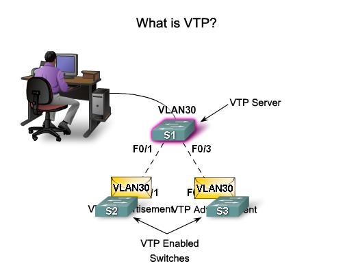
89 What is VTP? VTP allows a network manager to configure a switch so that it will propagate VLAN configurations to other switches in the network. The switch can be configured in the role of a VTP server or a VTP client. VTP server distributes and synchronizes VLAN information to VTP-enabled switches throughout the switched network VTP only learns about normal-range VLANs (VLAN IDs 1 to 1005). Extended-range VLANs (IDs greater than 1005) are not supported by VTP. 89

90 VTP benefits 90

91 VTP Components VTP Domain: consists of one or more interconnected switches. All switches in a domain share VLAN configuration details using VTP advertisements. A router or Layer 3 switch defines the boundary of each domain. VTP Advertisements : VTP uses a hierarchy of advertisements to distribute and synchronize VLAN configurations across the network. VTP Modes: A switch can be configured in one of three modes: server, client, or transparent. VTP Pruning: VTP pruning increases network available bandwidth by restricting flooded traffic to those trunk links that the traffic must use to reach the destination devices. 91
92 Dynamic Trunking Protocol Introduction to DTP Switch ports can be manually configured to form trunks Switch ports can also be configured to negotiate and establish a trunk link with a connected peer Dynamic Trunking Protocol (DTP) is a protocol to manage trunk negotiation DTP is a Cisco proprietary protocol and is enabled by default in Cisco Catalyst 2960 and 3560 switches If the port on the neighbor switch is configured in a trunk mode that supports DTP, it manages the negotiation The default DTP configuration for Cisco Catalyst 2960 and 3560 switches is dynamic auto 92

93 Dynamic Trunking Protocol Negotiated Interface Modes Cisco Catalyst 2960 and 3560 support the following trunk modes: switchport mode dynamic auto switchport mode dynamic desirable switchport mode trunk switchport nonegotiate 93
94 Routing Concepts Routing Protocols 94

95 Functions of a Router Why Routing? The router is responsible for the routing of traffic between networks. 95

96 Functions of a Router Routers Interconnect Networks Routers can connect multiple networks. Routers have multiple interfaces, each on a different IP network. 96
97 Functions of a Router Routers Choose Best Paths Determine the best path to send packets Uses its routing table to determine path Forward packets toward their destination Forwards packet to interface indicated in routing table. Encapsulates the packet and forwards out toward destination. Routers use static routes and dynamic routing protocols to learn about remote networks and build their routing tables. 97

98 Functions of a Router Packet Forwarding Methods Process switching An older packet forwarding mechanism still available for Cisco routers. Fast switching A common packet forwarding mechanism which uses a fast-switching cache to store next hop information. Cisco Express Forwarding (CEF) The most recent, fastest, and preferred Cisco IOS packet-forwarding mechanism. Table entries are not packet-triggered like fast switching but change-triggered. 98

99 Connect Devices Default Gateways To enable network access devices must be configured with the following IP address information IP address - Identifies a unique host on a local network. Subnet mask - Identifies the host s network subnet. Default gateway - Identifies the router a packet is sent to to when the destination is not on the same local network subnet. 99

100 Connect Devices Document Network Addressing Network Documentation should include at least the following in a topology diagram and addressing table: Device names Interfaces IP addresses and subnet mask Default gateways 100
101 Connect Devices Enable IP on a Host Statically Assigned IP address host is manually assigned the IP address, subnet mask and default gateway. DNS server IP address can also be assigned. Used to identify specific network resources such as network servers and printers Can be used in very small networks with few hosts. Dynamically Assigned IP Address IP Address information is dynamically assigned by a server using Dynamic Host Configuration Protocol (DHCP) Most hosts acquire their IP address information through DHCP 101

102 Connect Devices Enable IP on a Switch Network infrastructure devices require IP addresses to enable remote management. On a switch the management IP address is assigned on a virtual interface 102

103 Basic Settings on a Router Configure Basic Router Settings Basics tasks that should be first configured on a Cisco Router and Cisco Switch: Name the device Distinguishes it from other routers Secure management access Secures privileged EXEC, user EXEC, and Telnet access, and encrypts passwords to their highest level Configure a banner Provides legal notification of unauthorized access. 103

104 Basic Settings on a Router Configure Router Interfaces To be available a router interface must be: Configured with an address and subnet mask. Activated by default LAN and WAN interfaces are not activated. Must be activated using no shutdown command. Other parameters - serial cable end labeled DCE must be configured with the clock rate command. Optional description can be included. 104

105 Basic Settings on a Router Configure a Loopback Interface Loopback interface is a logical interface internal to the router. It is not assigned to a physical port, it is considered a software interface that is automatically in an UP state. Useful for testing and important in the OSPF routing process. 105

106 Verify Connectivity of Directly Connected Networks Verify Interface Settings Show commands to verify operation and configuration of interface. show ip interfaces brief show ip route show running-config Show commands to gather more detailed interface information. show interfaces show ip interfaces 106

107 Switching Packets between Networks Router Switching Functions 107

108 Switching Packets between Networks Send a Packet 108

109 Switching Packets between Networks Forward to the Next Hop 109

110 Switching Packets between Networks Packet Routing 110

111 Switching Packets between Networks Reach the Destination 111

112 Path Determination Routing Decisions 112
113 Path Determination Best Path Best path is selected by a routing protocol based on the value or metric it uses to determine the distance to reach a network. A metric is the value used to measure the distance to a given network. Best path to a network is the path with the lowest metric. Dynamic routing protocols use their own rules and metrics to build and update routing tables for example: Routing Information Protocol (RIP) - Hop count Open Shortest Path First (OSPF) - Cost based on cumulative bandwidth from source to destination Enhanced Interior Gateway Routing Protocol (EIGRP) - Bandwidth, delay, load, reliability 113
114 Path Determination Load Balancing When a router has two or more paths to a destination with equal cost metrics, then the router forwards the packets using both paths equally. 114
 Administrative Distance (AD). Administrative Distance is the trustworthiness of the route The Lower the AD the more trustworthy the route.")
115 Path Determination of the route Administrative Distance If multiple paths to a destination are configured on a router, the path installed in the routing table is the one with the best (lowest) Administrative Distance (AD). Administrative Distance is the trustworthiness of the route The Lower the AD the more trustworthy the route. 115

116 The Routing Table The Routing Table Routing Table is a file stored in RAM that contains information about Directly Connected Routes Remote Routes Network or Next hop Associations 116
117 The Routing Table Routing Table Sources Show ip route command is used to display the contents of the routing table Directly connected interfaces -Added to the routing table when an interface is configured and active. Static routes - Added when a route is manually configured and the exit interface is active. Dynamic routing protocol - Added when EIGRP or OSPF are implemented and networks are identified. 117

118 The Routing Table Routing Table Sources 118

119 The Routing Table Remote Network Routing Entries Interpreting the entries in the routing table. 119
120 Directly Connected Routes Directly Connected Interfaces A newly deployed router, without any configured interfaces, has an empty routing table. An active, configured directly connected interface creates two routing table entries Link Local (L) and Directly Connected (C) 120

121 Directly Connected Routes Directly Connected Interfaces A newly deployed router, without any configured interfaces, has an empty routing table. An active, configured directly connected interface creates two routing table entries Link Local (L) and Directly Connected (C) 121
122 Statically Learned Routes Static Routes Manually configured Define an explicit path between two networking devices. Must be manually updated if the topology changes. Benefits include improved security and control of resources. Static route to a specific network. ip routenetworkmask {next-hop-ip exit-intf} Default Static Route used when the routing table does not contain a path for a destination network. ip route {exit-intf next-hop-ip 122

123 Statically Learned Routes Static Routes Example 123

124 Dynamic Routing Protocols Dynamic Routing Used by routers to share information about the reachability and status of remote networks. Performs network discovery and maintaining routing tables. 124
125 Dynamic Routing Protocols IPv4 Routing Protocols Cisco ISR routers can support a variety of dynamic IPv4 routing protocols including: EIGRP Enhanced Interior Gateway Routing Protocol OSPF Open Shortest Path First IS-IS Intermediate System-to-Intermediate System RIP Routing Information Protocol 125

126 Dynamic Routing Protocols IPv4 Routing Protocols 126
127 Inter-VLAN Routing Routing And Switching 127

128 Inter-VLAN Routing Operation What is Inter-VLAN Routing? Layer 2 switches can t forward traffic between VLANs without the assistance of a router Inter-VLAN routing is a process for forwarding network traffic from one VLAN to another using a router 128
129 Inter-VLAN Routing Operation Router-On-A-Stick Inter-VLAN Routing The so called router-on-a-stick approach uses a different path to route between VLANs One of the router s physical interfaces is configured as a 802.1Q trunk port. Now that interface can understand VLAN tags Logical sub-interfaces are then created. One subinterface per VLAN Each sub-interface is configured with an IP address from the VLAN it represents VLAN members (hosts) are configured to use the subinterface address as a default gateway. Only one of the router s physical interface is used 129
130 Inter-VLAN Routing Operation Multilayer Switch Inter-VLAN Routing Multilayer switches can perform Layer 2 and Layer 3 functions. Routers are not required anymore Each VLAN existent in the switch is a SVI SVI are seen as layer 3 interfaces The switch understands network layer PDUs and therefore, it can route between its SVIs just as a router routes between its interfaces With a multilayer switch, traffic is routed internal to the switch device Very scalable solution 130
131 Configure Router-On-A-Stick Preparation An alternative to legacy inter-vlan routing is to use VLAN trunking and sub-interfaces VLAN trunking allows a single physical router interface to route traffic for multiple VLANs The physical interface of the router must be connected to a trunk link on the adjacent switch On the router, sub-interfaces are created for each unique VLAN on the network Each sub-interface is assigned an IP address specific to its subnet/vlan and is also configured to tag frames for that VLAN 131

132 Configure Router-On-A-Stick Switch Configuration 132

133 Configure Router-On-A-Stick Router Interface Configuration 133

134 Configure Router-On-A-Stick Verifying Sub-interfaces 134

135 Configure Router-On-A-Stick Verifying Sub-interfaces 135
136 Configure Router-On-A-Stick Verifying Routing Access to devices on remote VLANs can be tested using the ping command. The ping command sends an ICMP echo request to the destination address When a host receives an ICMP echo request, it responds with an ICMP echo reply Tracert is a useful utility for confirming the routed path taken between two devices 136
137 Layer 3 Switching Operation And Configuration Introduction To Layer 3 Switching Layer 3 switches usually have packet-switching throughputs in the millions of packets per second (pps) All Catalyst switches support two types of Layer 3 interfaces: Routed Port SVI High-performance switches, such as the Catalyst 6500 and Catalyst 4500, are able to perform most of the router s functions But several models of Catalyst switches require enhanced software for specific routing protocol feature 137
138 Layer 3 Switching Operation And Configuration Inter-VLAN Routing with SVIs Today routing has become faster and cheaper and can performed at hardware speed It can be transferred to core and distribution devices with little to no impact on network performance Many users are in separate VLANs, and each VLAN is usually a separate subnet This implies that each distribution switch must have IP addresses matching each access switch VLAN Layer 3 (routed) ports are normally implemented between the distribution and the core layer 138
139 Layer 3 Switching Operation And Configuration Inter-VLAN Routing with SVIs (cont) By default, an SVI is created for the default VLAN (VLAN1). This allows for remote switch administration Any additional SVIs must be created by the admin SVIs are created the first time the VLAN interface configuration mode is entered for a particular VLAN SVI The interface vlan 10 entered by the first time creates an SVI named VLAN 10 The VLAN number used corresponds to the VLAN tag associated with data frames on an 802.1Q encapsulated trunk Whenever the SVI is created, ensure that particular VLAN is present in the VLAN database 139
140 Layer 3 Switching Operation And Configuration Inter-VLAN Routing with SVIs (cont) SVIs advantages include: It is much faster than router-on-a-stick, because everything is hardware switched and routed. No need for external links from the switch to the router for routing. Not limited to one link. Layer 2 EtherChannels can be used between the switches to get more bandwidth. Latency is much lower, because it does not need to leave the switch. 140
141 Troubleshooting Layer 3 Switching Layer 3 Switching Configuration Issues To troubleshoot Layer 3 switching issues, check the following items for accuracy: VLANs VLANs must be defined across all the switches VLANs must be enabled on the trunk ports Ports must be in the right VLANs SVIs SVI must have the correct IP address or subnet mask SVI must be up SVI must match with the VLAN number 141
142 Troubleshooting Layer 3 Switching Layer 3 Switching Configuration Issues To troubleshoot Layer 3 switching issues, check the following items for accuracy (cont): Routing Routing must be enabled Each interface or network should be added to the routing protocol Hosts Hosts must have the correct IP address or subnet mask Hosts must have a default gateway associated with an SVI or routed port 142
Chapter 4: Routing Concepts. Routing & Switching
 Chapter 4: Routing Concepts Routing & Switching Routers are Computers Routers are specialized computers containing the following required components to operate: Central processing unit (CPU) Operating
CHAPTER 1: VLANS. Routing & Switching
 CHAPTER 1: VLANS Routing & Switching CHAPTER 1 1.1 VLAN Segmentation 1.2 VLAN Implementation 1.3 VLAN Security and Design 1.4 Summary CHAPTER 1 : OBJECTIVES Explain the purpose of VLANs in a switched network.
Chapter 3: VLANs. Routing & Switching
 Chapter 3: VLANs Routing & Switching VLAN Definitions A VLAN is a logical partition of a Layer 2 network. VLANs logically group hosts, regardless of physical location. Multiple partitions can be created,
Configuring VLANs. Understanding VLANs CHAPTER
 CHAPTER 12 This chapter describes how to configure normal-range VLANs (VLAN IDs 1 to 1005) and extended-range VLANs (VLAN IDs 1006 to 4094) on the switch. It includes information about VLAN membership
Configuring VLANs. Understanding VLANs CHAPTER
 CHAPTER 14 This chapter describes how to configure normal-range VLANs (VLAN IDs 1 to 1005) and extended-range VLANs (VLAN IDs 1006 to 4094) on the Catalyst 3750 switch. It includes information about VLAN
Configuring VLANs. Understanding VLANs CHAPTER
 CHAPTER 9 This chapter describes how to configure normal-range VLANs (VLAN IDs 1 to 1005) and extended-range VLANs (VLAN IDs 1006 to 4094). It includes information about VLAN membership modes, VLAN configuration
Configuring VLANs. Understanding VLANs CHAPTER
 CHAPTER 10 This chapter describes how to configure normal-range VLANs (VLAN IDs 1 to 1005) and extended-range VLANs (VLAN IDs 1006 to 4094) on the switch. It includes information about VLAN membership
Configuring VLANs. Understanding VLANs CHAPTER
 CHAPTER 11 This chapter describes how to configure normal-range VLANs (VLAN IDs 1 to 1005) and extended-range VLANs (VLAN IDs 1006 to 4094) on your Catalyst 3550 switch. It includes information about VLAN
Configuring Interface Characteristics
 CHAPTER 10 This chapter defines the types of interfaces on the switch and describes how to configure them. Unless otherwise noted, the term switch refers to a standalone switch and to a switch stack. The
Configuring VLANs. Understanding VLANs CHAPTER
 CHAPTER 11 This chapter describes how to configure normal-range VLANs (VLAN IDs 1 to 1005) and extended-range VLANs (VLAN IDs 1006 to 4094) on the Cisco ME 3400 Ethernet Access switch. It includes information
Configuring VLANs. Understanding VLANs CHAPTER
 CHAPTER 16 This chapter describes how to configure normal-range VLANs (VLAN IDs 1 to 1005) and extended-range VLANs (VLAN IDs 1006 to 4094) on your Catalyst 2950 or Catalyst 2955 switch. It includes information
Configuring Private VLANs
 CHAPTER 15 This chapter describes how to configure private VLANs on the Cisco 7600 series routers. Note For complete syntax and usage information for the commands used in this chapter, refer to the Cisco
Skills Assessment (OSPF) Student Training Exam
 Student Training Exam") Skills Assessment (OSPF) Student Training Exam Topology Cisco and/or its affiliates. All rights reserved. This document is Cisco Public. Page 1 of 16 Addressing Table Device Interface IP Address Subnet
Skills Assessment (OSPF) Student Training Exam Topology Cisco and/or its affiliates. All rights reserved. This document is Cisco Public. Page 1 of 16 Addressing Table Device Interface IP Address Subnet
Skills Assessment (OSPF) Student Training Exam
 Student Training Exam") Skills Assessment (OSPF) Student Training Exam Topology 2013 Cisco and/or its affiliates. All rights reserved. This document is Cisco Public. Page 1 of 17 Addressing Table Assessment Objectives Device
Skills Assessment (OSPF) Student Training Exam Topology 2013 Cisco and/or its affiliates. All rights reserved. This document is Cisco Public. Page 1 of 17 Addressing Table Assessment Objectives Device
Preview Test: cis191_chap1_quiz
 3/9/2015 Preview Test: cis191_chap1_quiz 20155229528. Sunyata 98 Courses Organizations Need Help? Prevent Sexual Violence Preview Test: cis191_chap1_quiz Test Information Description Instructions Timed
Skills Assessment (EIGRP) Student Training Exam
 Student Training Exam") Skills Assessment (EIGRP) Student Training Exam Topology Cisco and/or its affiliates. All rights reserved. This document is Cisco Public. Page 1 of 15 Addressing Table Device Interface IP Address Subnet
Skills Assessment (EIGRP) Student Training Exam Topology Cisco and/or its affiliates. All rights reserved. This document is Cisco Public. Page 1 of 15 Addressing Table Device Interface IP Address Subnet
CCNA Routing and Switching (NI )
") CCNA Routing and Switching (NI400+401) 150 Hours ` Outline The Cisco Certified Network Associate (CCNA) Routing and Switching composite exam (200-125) is a 90-minute, 50 60 question assessment that is
CCNA Routing and Switching (NI400+401) 150 Hours ` Outline The Cisco Certified Network Associate (CCNA) Routing and Switching composite exam (200-125) is a 90-minute, 50 60 question assessment that is
Cisco Certified Network Associate ( )
") Cisco Certified Network Associate (200-125) Exam Description: The Cisco Certified Network Associate (CCNA) Routing and Switching composite exam (200-125) is a 90-minute, 50 60 question assessment that
Cisco Certified Network Associate (200-125) Exam Description: The Cisco Certified Network Associate (CCNA) Routing and Switching composite exam (200-125) is a 90-minute, 50 60 question assessment that
Configuring Private VLANs
 Finding Feature Information, on page 1 Prerequisites for Private VLANs, on page 1 Restrictions for Private VLANs, on page 1 Information About Private VLANs, on page 2 How to Configure Private VLANs, on
VLAN Configuration. Understanding VLANs CHAPTER
 CHAPTER 11 This chapter describes how to configure normal-range VLANs (VLAN IDs 1 to 1005) and extended-range VLANs (VLAN IDs 1006 to 4094) on the CGR 2010 ESM. It includes information about VLAN membership
CCNA Cisco Certified Network Associate CCNA (v3.0)
") 200-125 - CCNA Cisco Certified Network Associate CCNA (v3.0) 1.What is one benefit of PVST+? A. PVST+ supports Layer 3 load balancing without loops. B. PVST+ reduces the CPU cycles for all the switches
200-125 - CCNA Cisco Certified Network Associate CCNA (v3.0) 1.What is one benefit of PVST+? A. PVST+ supports Layer 3 load balancing without loops. B. PVST+ reduces the CPU cycles for all the switches
CCNA. Murlisona App. Hiralal Lane, Ravivar Karanja, Near Pethe High-School, ,
 CCNA Cisco Certified Network Associate (200-125) Exam DescrIPtion: The Cisco Certified Network Associate (CCNA) Routing and Switching composite exam (200-125) is a 90-minute, 50 60 question assessment
3. What could you use if you wanted to reduce unnecessary broadcast, multicast, and flooded unicast packets?
 Nguyen The Nhat - Take Exam Exam questions Time remaining: 00: 00: 51 1. Which command will give the user TECH privileged-mode access after authentication with the server? username name privilege level
PASS4TEST IT 인증시험덤프전문사이트
 PASS4TEST IT 인증시험덤프전문사이트 http://www.pass4test.net 일년동안무료업데이트 Exam : 640-802 Title : Cisco Certified Network Associate(CCNA) Vendors : Cisco Version : DEMO 1 / 10 Get Latest & Valid 640-802 Exam's Question
Configuring VLANs. Understanding VLANs CHAPTER
 CHAPTER 14 This chapter describes how to configure normal-range VLANs (VLAN IDs 1 to 1005) and extended-range VLANs (VLAN IDs 1006 to 4094). It includes information about VLAN modes and the VLAN Membership
Skills Assessment (EIGRP) Student Training Exam
 Student Training Exam") Skills Assessment (EIGRP) Student Training Exam Topology 2013 Cisco and/or its affiliates. All rights reserved. This document is Cisco Public. Page 1 of 16 Addressing Table Assessment Objectives Device
Skills Assessment (EIGRP) Student Training Exam Topology 2013 Cisco and/or its affiliates. All rights reserved. This document is Cisco Public. Page 1 of 16 Addressing Table Assessment Objectives Device
TEXTBOOK MAPPING CISCO COMPANION GUIDES
 TestOut Routing and Switching Pro - English 6.0.x TEXTBOOK MAPPING CISCO COMPANION GUIDES Modified 2018-08-20 Objective Mapping: Cisco 100-105 ICND1 Objective to LabSim Section # Exam Objective TestOut
Introduction to OSPF
 Campus Networking Introduction to OSPF Workshop Campus Layer-2 Networking Network Workshop Design These materials are licensed under the Creative Commons Attribution-Noncommercial 3.0 Unported license
Cisco Exploration 3 Module 3 LAN Switching and Wireless Jim Johnston Class Notes September 9, 2008
 Cisco Exploration 3 Module 3 LAN Switching and Wireless Jim Johnston Class Notes September 9, 2008 VLAN is a logically separate IP subnetwork. This allows multiple networks to exist on a switch and provide
Lab 1-2Connecting to a Cisco Router or Switch via Console. Lab 1-6Basic Graphic Network Simulator v3 Configuration
 MODULE1 GETTING STARTED WITH YOUR CISCO LAB Lab 1-1Identifying Router Components and Accessories Lab 1-2Connecting to a Cisco Router or Switch via Console Lab 1-3Identifying Router & Switch IOS Software
For information about configuring these settings from Cluster Management Suite (CMS), refer to the online help.
, refer to the online help.") Configuring VLANs This chapter provides information about configuring virtual LANs (VLANs). It includes command-line interface (CLI) procedures for using commands that have been specifically created or
Configuring VLANs This chapter provides information about configuring virtual LANs (VLANs). It includes command-line interface (CLI) procedures for using commands that have been specifically created or
Configuring STP and RSTP
 7 CHAPTER Configuring STP and RSTP This chapter describes the IEEE 802.1D Spanning Tree Protocol (STP) and the ML-Series implementation of the IEEE 802.1W Rapid Spanning Tree Protocol (RSTP). It also explains
Configuring VLANs. Understanding VLANs CHAPTER
 7 CHAPTER This chapter describes how to configure normal-range VLANs (VLAN IDs 1 to 1005) and extended-range VLANs (VLAN IDs 1006 to 4094) on the Cisco MWR 2941 router. It includes information about VLAN
Maintaining Specific VLAN Identification. Comparing ISL and 802.1Q. VLAN Trunking
 Maintaining Specific VLAN Identification Specifically developed for multi-vlan interswitch communications Places a unique identifier in each frame Functions at Layer 2 2003, Cisco Systems, Inc. All rights
Campus Networking Workshop. Layer 2 engineering Spanning Tree and VLANs
 Campus Networking Workshop Layer 2 engineering Spanning Tree and VLANs Switching Loop When there is more than one path between two switches What are the potential problems? Switching Loop If there is more
VLANs. Traditional Campus Networks. Performance Issues. Broadcast Issues. Bridges terminate collision domains
 Traditional Campus Networks Broadcast Domain VLANs Collision Domain 1 Collision Domain 2 Bridges terminate collision domains 2003, Cisco Systems, Inc. All rights reserved. 2-1 2003, Cisco Systems, Inc.
Configuring Rapid PVST+
 This chapter describes how to configure the Rapid per VLAN Spanning Tree (Rapid PVST+) protocol on Cisco NX-OS devices using Cisco Data Center Manager (DCNM) for LAN. For more information about the Cisco
Configuring Rapid PVST+ Using NX-OS
 Configuring Rapid PVST+ Using NX-OS This chapter describes how to configure the Rapid per VLAN Spanning Tree (Rapid PVST+) protocol on Cisco NX-OS devices. This chapter includes the following sections:
Configuring STP. Understanding Spanning-Tree Features CHAPTER
 CHAPTER 11 This chapter describes how to configure the Spanning Tree Protocol (STP) on your switch. For information about the Rapid Spanning Tree Protocol (RSTP) and the Multiple Spanning Tree Protocol
Top-Down Network Design, Ch. 7: Selecting Switching and Routing Protocols. Top-Down Network Design. Selecting Switching and Routing Protocols
 Top-Down Network Design Chapter Seven Selecting Switching and Routing Protocols Copyright 2010 Cisco Press & Priscilla Oppenheimer 1 Switching 2 Page 1 Objectives MAC address table Describe the features
VLANs. 2003, Cisco Systems, Inc. All rights reserved. 2-1
 VLANs 2003, Cisco Systems, Inc. All rights reserved. 2-1 Traditional Campus Networks Broadcast Domain Collision Domain 1 Collision Domain 2 Bridges terminate collision domains 2003, Cisco Systems, Inc.
VLANs. 2003, Cisco Systems, Inc. All rights reserved. 2-1
 VLANs 2003, Cisco Systems, Inc. All rights reserved. 2-1 Traditional Campus Networks Broadcast Domain Collision Domain 1 Collision Domain 2 Bridges terminate collision domains 2003, Cisco Systems, Inc.
Configuring EtherChannels and Link-State Tracking
 CHAPTER 37 Configuring EtherChannels and Link-State Tracking This chapter describes how to configure EtherChannels on Layer 2 and Layer 3 ports on the switch. EtherChannel provides fault-tolerant high-speed
Top-Down Network Design
 Top-Down Network Design Chapter Seven Selecting Switching and Routing Protocols Original slides by Cisco Press & Priscilla Oppenheimer Selection Criteria for Switching and Routing Protocols Network traffic
Building Cisco Multilayer Switched Networks (BCMSN)
") Building Cisco Multilayer Switched Networks (BCMSN) Table of Contents Module 1 Defining VLANs Implementing Best Practices for VLAN Topologies Describing Issues in a Poorly Designed Network Grouping Business
Building Cisco Multilayer Switched Networks (BCMSN) Table of Contents Module 1 Defining VLANs Implementing Best Practices for VLAN Topologies Describing Issues in a Poorly Designed Network Grouping Business
 Seite von 7 05.0.200 Close Window Assessment System Exam Viewer - CCNA Practice Certification Exam # - (Version 4.0) Below you will find the assessment items as presented on the exam as well as the scoring
Exam Topics Cross Reference
 Appendix R Exam Topics Cross Reference This appendix lists the exam topics associated with the ICND1 100-105 exam and the CCNA 200-125 exam. Cisco lists the exam topics on its website. Even though changes
Configuring EtherChannels and Layer 2 Trunk Failover
 35 CHAPTER Configuring EtherChannels and Layer 2 Trunk Failover This chapter describes how to configure EtherChannels on Layer 2 and Layer 3 ports on the switch. EtherChannel provides fault-tolerant high-speed
CCNA Semester 3 labs. Part 1 of 1 Labs for chapters 1 8
 CCNA Semester 3 labs Part 1 of 1 Labs for chapters 1 8 2.1.2.12 Lab - Building a Switched Network with Redundant Links 2.3.2.3 Lab - Configuring Rapid PVST+, PortFast and BPDU Guard 2.4.3.4 Lab - Configuring
Configuring Interfaces
 CHAPTER 9 This chapter defines the types of interfaces on the Cisco ME 3400 Ethernet Access switch and describes how to configure them. The chapter consists of these sections: Understanding Interface Types,
CCNP SWITCH (22 Hours)
") CCNP SWITCH 642-813 (22 Hours) Chapter-1 Enterprise Campus Network Design 1.1 IIN & SONA 1.2 Campus Network 1.3 Enterprise Model 1.4 Nonhierarchical Network Devices Layer-2 Switching, Layer-3 Routing Multilayer
CCNP SWITCH 642-813 (22 Hours) Chapter-1 Enterprise Campus Network Design 1.1 IIN & SONA 1.2 Campus Network 1.3 Enterprise Model 1.4 Nonhierarchical Network Devices Layer-2 Switching, Layer-3 Routing Multilayer
Introducing Campus Networks
 Cisco Enterprise Architecture Introducing Campus Networks 2003, Cisco Systems, Inc. All rights reserved. 2-1 2003, Cisco Systems, Inc. All rights reserved. BCMSN v2.0 2-2 Campus Data Center Combines switching
Implement Inter-VLAN Routing. LAN Switching and Wireless Chapter 6 Modified by Tony Chen 11/01/2008
 Implement Inter-VLAN Routing LAN Switching and Wireless Chapter 6 Modified by Tony Chen 11/01/2008 ITE I Chapter 6 2006 Cisco Systems, Inc. All rights reserved. Cisco Public 1 Notes: If you see any mistake
CISCO EXAM QUESTIONS & ANSWERS
 CISCO 100-101 EXAM QUESTIONS & ANSWERS Number: 100-101 Passing Score: 800 Time Limit: 120 min File Version: 35.5 http://www.gratisexam.com/ CISCO 100-101 EXAM QUESTIONS & ANSWERS Exam Name: CCNA Interconnecting
Chapter 2. Switch Concepts and Configuration. Part I
 Chapter 2 Switch Concepts and Configuration Part I CCNA3-1 Chapter 2-1 Note for Instructors These presentations are the result of a collaboration among the instructors at St. Clair College in Windsor,
TestOut Routing and Switching Pro - English 6.0.x COURSE OUTLINE. Modified
 TestOut Routing and Switching Pro - English 6.0.x COURSE OUTLINE Modified 2017-07-10 TestOut Routing and Switching Pro Outline- English 6.0.x Videos: 133 (15:42:34) Demonstrations: 78 (7:22:19) Simulations:
Configuring Interface Characteristics
 Finding Feature Information, page 1 Information About, page 1 How to Configure Interface Characteristics, page 11 Monitoring Interface Characteristics, page 28 Configuration Examples for Interface Characteristics,
Configuring Interface Characteristics
 CHAPTER 11 This chapter defines the types of interfaces on the Catalyst 3750 switch and describes how to configure them. Unless otherwise noted, the term switch refers to a standalone switch and a switch
CCNA Exploration Network Fundamentals
 CCNA Exploration 4.0 1. Network Fundamentals The goal of this course is to introduce you to fundamental networking concepts and technologies. These online course materials will assist you in developing
Configuring EtherChannels
 27 CHAPTER This chapter describes how to configure EtherChannel on Layer 2 interfaces. EtherChannel provides fault-tolerant high-speed links between switches, routers, and servers. You can use it to increase
CCNA 1 Chapter 5 v5.0 Exam Answers 2013
 CCNA 1 Chapter 5 v5.0 Exam Answers 2013 1 2 A host is trying to send a packet to a device on a remote LAN segment, but there are currently no mappings in its ARP cache. How will the device obtain a destination
Interconnecting Cisco Networking Devices Part 1 (ICND1) Course Overview
 Course Overview") Interconnecting Cisco Networking Devices Part 1 (ICND1) Course Overview This course will teach students about building a simple network, establishing internet connectivity, managing network device security,
Interconnecting Cisco Networking Devices Part 1 (ICND1) Course Overview This course will teach students about building a simple network, establishing internet connectivity, managing network device security,
Switching & ARP Week 3
 Switching & ARP Week 3 Module : Computer Networks Lecturer: Lucy White lbwhite@wit.ie Office : 324 Many Slides courtesy of Tony Chen 1 Ethernet Using Switches In the last few years, switches have quickly
Configuring VLANs. Finding Feature Information. Prerequisites for VLANs
 Finding Feature Information, page 1 Prerequisites for VLANs, page 1 Restrictions for VLANs, page 2 Information About VLANs, page 2 How to Configure VLANs, page 7 Monitoring VLANs, page 19 Where to Go Next,
Chapter 5: Inter-VLAN Routing. Routing & Switching
 Chapter 5: Inter-VLAN Routing Routing & Switching What is Inter-VLAN routing? Layer 2 switches cannot forward traffic between VLANs without the assistance of a router. Inter-VLAN routing is a process for
Configuring VLAN Trunks
 Finding Feature Information, page 1 Prerequisites for VLAN Trunks, page 1 Information About VLAN Trunks, page 2 How to Configure VLAN Trunks, page 5 Configuration Examples for VLAN Trunking, page 20 Where
Configuring Interfaces
 CHAPTER 9 This chapter defines the types of interfaces on the Cisco ME 3400 Ethernet Access switch and describes how to configure them. Understanding Interface Types, page 9-1 Using Interface Configuration
Configuring Private VLANs
 36 CHAPTER This chapter describes private VLANs (PVLANs) on Catalyst 4500 series switches. It also provides restrictions, procedures, and configuration examples. This chapter includes the following major
Chapter 5 Reading Organizer After completion of this chapter, you should be able to:
 Chapter 5 Reading Organizer After completion of this chapter, you should be able to: Describe the operation of the Ethernet sublayers. Identify the major fields of the Ethernet frame. Describe the purpose
COPYRIGHTED MATERIAL. Table of Contents. Assessment Test
 10089.book Page xi Monday, July 23, 2007 3:17 PM Introduction Assessment Test xxiii xxxiii Chapter 1 Internetworking 1 Internetworking Basics 4 Internetworking Models 11 The Layered Approach 12 Advantages
Configuring StackWise Virtual
 Finding Feature Information, page 1 Restrictions for Cisco StackWise Virtual, page 1 Prerequisites for Cisco StackWise Virtual, page 2 Information About Cisco Stackwise Virtual, page 2 Cisco StackWise
SEMESTER 2 Chapter 1 Planning and Cabling a Network V 4.0
 SEMESTER 2 Chapter 1 Planning and Cabling a Network V 4.0 135 points 1.1.1 What are the common components between a router and other computers? CPU RAM ROM Operating System 1.1.1.2 What does a router connect?
CCNA 3 (v v6.0) Chapter 3 Exam Answers % Full
 Chapter 3 Exam Answers % Full") CCNA 3 (v5.0.3 + v6.0) Chapter 3 Exam Answers 2017 100% Full ccnav6.com /ccna-3-v5-0-3-v6-0-chapter-3-exam-answers-2017-100-full.html CCNA Exam Answers 2017 CCNA 3 (v5.0.3 + v6.0) Chapter 3 Exam Answers
CCNA 3 (v5.0.3 + v6.0) Chapter 3 Exam Answers 2017 100% Full ccnav6.com /ccna-3-v5-0-3-v6-0-chapter-3-exam-answers-2017-100-full.html CCNA Exam Answers 2017 CCNA 3 (v5.0.3 + v6.0) Chapter 3 Exam Answers
Internetwork Expert s CCNA Security Bootcamp. Mitigating Layer 2 Attacks. Layer 2 Mitigation Overview
 Internetwork Expert s CCNA Security Bootcamp Mitigating Layer 2 Attacks http:// Layer 2 Mitigation Overview The network is only as secure as its weakest link If layer 2 is compromised, all layers above
CERTIFICATE CCENT + CCNA ROUTING AND SWITCHING INSTRUCTOR: FRANK D WOUTERS JR. CETSR, CSM, MIT, CA
 CERTIFICATE CCENT + CCNA ROUTING AND SWITCHING INSTRUCTOR: FRANK D WOUTERS JR. CETSR, CSM, MIT, CA CCENT - Cisco Certified Entry Networking Technician (ICND1) CCNA Routing and Switching (ICND2) Prerequisites:
Configuring Spanning Tree Protocol
 CHAPTER 7 This chapter descibes how to configure Spanning Tree Protocol (STP) on the Cisco wireless mobile interface card (WMIC). Note For complete syntax and usage information for the commands used in
Configuring SPAN and RSPAN
 CHAPTER 32 This chapter describes how to configure Switched Port Analyzer (SPAN) and Remote SPAN (RSPAN) on the Catalyst 3750-X or 3560-X switch. Unless otherwise noted, the term switch refers to a Catalyst
Actual4Test. Actual4test - actual test exam dumps-pass for IT exams
 Actual4Test http://www.actual4test.com Actual4test - actual test exam dumps-pass for IT exams Exam : 200-125 Title : CCNA Cisco Certified Network Associate CCNA (v3.0) Vendor : Cisco Version : DEMO Get
CCNA Semester 3 labs. Labs for chapters 2 10
 CCNA Semester 3 labs Labs for chapters 2 10 2.1.4.5 Lab - Configure Extended VLANs, VTP, and DTP 2.2.2.5 Lab - Troubleshooting Inter-VLAN Routing 3.1.2.12 Lab - Building a Switched Network with Redundant
Exam Questions
 Exam Questions 200-105 ICND2 Interconnecting Cisco Networking Devices Part 2 (ICND2 v3.0) https://www.2passeasy.com/dumps/200-105/ 1.At which layer of the OSI model is RSTP used to prevent loops? A. physical
CISCO EXAM QUESTIONS & ANSWERS
 CISCO 200-101 EXAM QUESTIONS & ANSWERS Number: 200-101 Passing Score: 800 Time Limit: 120 min File Version: 32.2 http://www.gratisexam.com/ CISCO 200-101 EXAM QUESTIONS & ANSWERS Exam Name: Interconnecting
cisco. Number: Passing Score: 800 Time Limit: 120 min.
 300-115.cisco Number: 300-115 Passing Score: 800 Time Limit: 120 min Exam A QUESTION 1 Which of the following statements best describes the result of issuing the instance 3 vlans 7 command? A. VLAN 7 is
Laboration 2 Troubleshooting Switching and First-Hop Redundancy
 Laboration 2 Troubleshooting Switching and First-Hop Redundancy Topology All contents are Copyright 1992 2011 Cisco Systems, Inc. All rights reserved. This document is Cisco Public Information. Page 1
2. What is a characteristic of a contention-based access method?
 CCNA 1 Chapter 5 v5.0 Exam Answers 2015 (100%) 1. Which statement is true about MAC addresses? MAC addresses are implemented by software. A NIC only needs a MAC address if connected to a WAN. The first
Switches Chapter 2 1
 Switches Chapter 2 1 Topics Operation of 100/1000 Mbps Ethernet Switches and how they forward frames Configure a switch Basic security on a switch 2 Semester 3 LAN Design Basic Switch Concepts Wireless
Cisco Questions & Answers
 Cisco 200-101 Questions & Answers Number: 200-101 Passing Score: 800 Time Limit: 120 min File Version: 23.7 http://www.gratisexam.com/ Cisco 200-101 Questions & Answers Exam Name: Interconnecting Cisco
itexamdump 최고이자최신인 IT 인증시험덤프 일년무료업데이트서비스제공
 itexamdump 최고이자최신인 IT 인증시험덤프 http://www.itexamdump.com 일년무료업데이트서비스제공 Exam : 642-813 Title : Implementing Cisco IP Switched Networks Vendor : Cisco Version : DEMO Get Latest & Valid 642-813 Exam's Question
exam. Number: Passing Score: 800 Time Limit: 120 min CISCO Interconnecting Cisco Networking Devices Part 1 (ICND)
") 100-105.exam Number: 100-105 Passing Score: 800 Time Limit: 120 min CISCO 100-105 Interconnecting Cisco Networking Devices Part 1 (ICND) Exam A QUESTION 1 Which route source code represents the routing
100-105.exam Number: 100-105 Passing Score: 800 Time Limit: 120 min CISCO 100-105 Interconnecting Cisco Networking Devices Part 1 (ICND) Exam A QUESTION 1 Which route source code represents the routing
CCNP Switch Questions/Answers Implementing VLANs in Campus Networks
 Refer to the exhibit. Given the configuration information of the CAT1 and CAT2 switches, which statement is true? A. LACP will form a channel between the switches. B. Because the port-channel numbers do
Lab 5: Inter-VLANs Routing
 Lab 5: Inter-VLANs Routing Network Topology:- Device Interface IP Address Subnet Mask Gateway/Clock Rate Fa 0/0.10 10.5.0.1 255.255.255.192 ----- R1 Fa 0/0.20 10.6.0.1 255.255.255.192 ----- Fa 0/0.30 10.10.0.1
Configuring EtherChannels and Layer 2 Trunk Failover
 28 CHAPTER Configuring EtherChannels and Layer 2 Trunk Failover This chapter describes how to configure EtherChannels on Layer 2 ports on the switch. EtherChannel provides fault-tolerant high-speed links
SWITCH Implementing Cisco IP Switched Networks
 Hands-On SWITCH Implementing Cisco IP Switched Networks CCNP Course 2 Course Description Revised CCNP Curriculum and Exams Cisco has redesigned the CCNP courses and exams to reflect the evolving job tasks
EIGRP Features and Operation
 EIGRP Features and Operation Enhanced IGRP (EIGRP) is a classless, enhanced distance-vector protocol. EIGRP is a Cisco proprietary protocol. EIGRP includes the subnet mask in its route updates. And as
Lab Configuring EtherChannel
 Topology Addressing Table Objectives Device Interface IP Address Subnet Mask S1 VLAN 99 192.168.99.11 255.255.255.0 S2 VLAN 99 192.168.99.12 255.255.255.0 S3 VLAN 99 192.168.99.13 255.255.255.0 PC-A NIC
Configuring EtherChannels and Link-State Tracking
 30 CHAPTER Configuring EtherChannels and Link-State Tracking This chapter describes how to configure EtherChannels on Layer 2 ports on the Catalyst 2960 switch. EtherChannel provides fault-tolerant high-speed
Configuring MPLS and EoMPLS
 37 CHAPTER This chapter describes how to configure multiprotocol label switching (MPLS) and Ethernet over MPLS (EoMPLS) on the Catalyst 3750 Metro switch. MPLS is a packet-switching technology that integrates
Cisco CCNA (ICND1, ICND2) Bootcamp
 Bootcamp") Cisco CCNA (ICND1, ICND2) Bootcamp Course Duration: 5 Days Course Overview This five-day course covers the essential topics of ICND1 and ICND2 in an intensive Bootcamp format. It teaches students the skills
Cisco CCNA (ICND1, ICND2) Bootcamp Course Duration: 5 Days Course Overview This five-day course covers the essential topics of ICND1 and ICND2 in an intensive Bootcamp format. It teaches students the skills
Guide to Networking Essentials, 6 th Edition. Chapter 7: Network Hardware in Depth
 Guide to Networking Essentials, 6 th Edition Chapter 7: Network Hardware in Depth Objectives Describe the advanced features and operation of network switches Describe routing table properties and discuss
Qus1:-What is cat stands for in networking?
 Qus1:-What is cat stands for in networking? Ans :- Cat stands for "CATEGORY". Which started from Cat1 (Category1) and now extend up to Cat7 (Category 7). Improved version/category of cable improve the
Top-Down Network Design
 Top-Down Network Design Chapter Five Designing a Network Topology Original slides copyright by Cisco Press & Priscilla Oppenheimer Network Topology Design Issues Hierarchy Redundancy Modularity Well-defined