How to stack multiple NCT192 IP DSLAMs in untagged mode and VLAN tagged mode
|
|
|
- Brenda Rodgers
- 6 years ago
- Views:
Transcription
1 How to stack multiple NCT192 IP DSLAMs in untagged mode and VLAN tagged mode Introduction The NetComm NCT port IP DSLAM supports service capacity expansion via unit stacking. A maximum of ten NCT192s are allowed to be stacked which makes a system to have 1920 ports in total. All the NCT192 in a stacked system will share a single uplink interface to connect to the backbone network. Refer to Figure 1 for a brief illustration to this implementation structure. The advantage of using the stacking topology implementation in comparison to a star topology implementation is that a Gigabit Ethernet switch can be eliminated. Refer to Figure 2 for an illustration of a star-topology implementation. This white paper is written to demonstrate the concept and fundamental procedures involved in setting up multiple NCT192 system for untagged and Virtual Local Area Network (VLAN) tagged application. This system stacking concept is demonstrated through setting up two NCT192 systems in stacking topology. This white paper contains two parts. Part 1 describes the steps and configuration in setting up two NCT192s in untagged mode; Part 2 describes that in VLAN tagged mode. It is recommended that the readers of this document have read and understood the NCT192 System Installation Guide, the Local Craft Terminal (LCT) software operation guide and the Command Line Interface (CLI) operation guide in the NCT192 user manual. It is assumed that readers of this document understand the concepts used in Virtual Local Area Network (VLAN), such as trunk mode and access mode. The configuration for the Gigabit Ethernet (GE) VLAN switch is not described in this white paper. page 1


2 Figure 1: NCT192s in stacking topology Figure 2: NCT192s in Star Topology page 2
3 Terms & Concepts VLAN VLAN stands for Virtual Local Area Network. It is a group of hosts with a common set of requirements that communicate as if they were attached to the same broadcast domain. A VLAN allows a physical network to be divided into several logical networks. An end device can be assigned to more than one VLAN group. Devices from different VLANs can not communicate to each other. VLAN can provide isolation and security to users and increase network performance by limiting broadcast domain. VLAN tag can be added to the MAC header to identify the VLAN membership of a frame across bridges. A tagged frame is four bytes longer than an untagged frame. The GE and xdsl interfaces of the NCT192 are capable of passing tagged or untagged frames. NCT192 Network Control (NC) card supports two global modes: Untagged only and Tagged only. This means when the NC card is configured in Untagged Mode, the traffic that going through the uplink or downlink interface of the IP DSLAM will be untagged. This also means when the NC card is configured in Tagged Mode, the traffic going through the uplink or downlink interface of the IP DSLAM will be tagged. For further NCT192 VLAN terms and concepts please refer the NCT192 User Manual. Stacked VLAN Database Management In a stacked NCT192 system, the VLAN database that is kept in each of the NCT192 is different. The NCT192 that connects the rest of the NCT192s to the backbone network has the entire VLAN database. Figure 3 illustrates the logical VLAN database location in each of the NCT192 in a stacked system. In Figure 3, all data traffic from NCT192 IP DSLAM_B goes through IP DSLAM A to reach their backbone network then to the Internet. Hence IP DSLAM A must keep a record of the VLANs from its local port as well as from IP DSLAM B to ensure all the VLAN tagged packets passes to the backbone network. Please note that the GE1 in IP DSLAM_A will need to be set to uplink mode and GE2 in subtended mode ; GE1 in IP DSLAM_B will need to be set to uplink mode and since GE2 in DSLAM_B is not used, it can be disabled. page 3
4 Figure 3: Stacked VLAN Database in NCT192 System Management The NCT192 supports SNMP, CLI, Telnet, FTP and TFTP for system management. A proprietary SNMP management program is used to manage NCT192 locally or remotely. This software is called the Local Craft Terminal (LCT) and it comes with the product CD ROM when the product is shipped. The NCT192 does not support single IP management in its current firmware. This means the management interface IP address for NCT192s will need to be different and you will need to connect to each system at a time to perform configuration. The default inbound management IP address for the NCT192 local management port is /24; the default outbound management IP address for NCT192 uplink port is via VLAN 2094 with IP address /16; the default user name and SNMP community for logging into the LCT is admin/netman. It is recommended to use the local management port for device management. Figure 5 illustrates how multiple NCT192s are managed. page 4
5 Figure 5: NCT192 System Management Profile Management A profile is a list of configuration parameters and it has a name that designated by the administrator of the NCT192 system. By using a profile, the administrator or operator can configure the IP DSLAM without having to key in every parameter settings all the time. This is called profile mapping (to xdsl ports). NCT192 builds in inter-profile relationship to its interfaces. When a profile is modified, the modification will affect all interfaces that were using that profile. There are two major categories of profiles in a NCT192 system. They are data transport related profiles and alarm definition profile. The alarm definition profile defines the attributes of the report (alarm) of abnormality launched by the NE. The data transport related profiles, it is further categorised into the xdsl Profile and VLAN Profile. The xdsl Profile indicates the ADSL Profile. It defines the attributes of the connection established via the xdsl subscriber loop. As to the VLAN Profile, it defines the attributes of services and applications applied to the xdsl subscriber. Figure 6 illustrated the inter-relationship of the Data Transport Related profiles in a NCT192 system. page 5

6 Figure 6: Interrelationship of Data Transport Related Profiles Different sets of profiles are required for different types of system deployments and applications. A uni-cast untagged and VLAN tagged application are described in this white paper where the Line profile, IP traffic profile and VC-to-VLAN batch configuration will be used. page 6
7 GE It stands for Gigabit Ethernet. It is the standard for a high-speed Ethernet. It has a maximum data transmission rate of 1000Mb/s or 1 Gigabit/s. LCT It stands for Local Craft Terminal. It is a name for the proprietary NCT192 management program. NCT192 LCT is a SNMP management program that can monitor and control one NCT192 IP DSLAM at a time. NE NE/NEs mentioned in this document means NCT192 IP DSLAM unless specifically indicated. xdsl It is refer ADSL in this document. It covers ADSL, ADSL2, and ADSL2+, unless specifically indicated. NC It stands for Network Card. One network card is required to be installed in each NCT192 IP DSLAM. The product code for NCT192 s NC card is NCT1902. This product code is displayed in LCT operation menu once the NC card completes initialization. LC It stands for Line Card. Each NCT192 LC card has 48 ADSL ports. There are a maximum of 4 ADSL LC cards can be installed in each NCT192 system which make a system to have a total of 192 ports in total. The product code for NCT192 s LC card is NCT1901. This product code is displayed in LCT operation menu once the LC card completes initialization. page 7
8 System Requirement This white paper is written using LCT to configure the stacked NCT192 system. It is recommended to use the following hardware and software to run the LCT software. Hardware: > Pentium GHz or higher > 512 MB RAM or higher > 40 GB Hard disk > 10/100 Base-T Ethernet network card Software: > Operating System Microsoft Windows 98SE/ME/2000/XP > NCT192 Installation Package (Refer to NCT192 product CD ROM) page 8
9 Equipment List Hardware 2 x NCT192 systems (with 1 x NCT1902 NC Card; 1 x NCT1901 LC card in each system) 2 x NCT192S POTS Splitter shelf (with 1 x NCT1901S POTS Splitter Card in each system) 4 x NCT2030 Power supply for NCT192 system 3 x NCT1911 Mini GBIC Fibre to Copper RJ45 GE Converters 6 x CAT5E RJ45 Ethernet Cables 1 x GE VLAN Switch 2 x NB6+4W_R2T8 Bridged Modem routers 2 x Splitter Filter 2 x NCT1906 DSLAM cables (6m Male 180 degrees connector to Open) 2 x NCT1904 DSLAM Cables (1m Male 90 degrees to 180 Male) 1 x DHCP Server or IP Network (acts as the backbone for the NCT192 system) Please note that the quantity of hardware items used in this whitepaper does not represent two fully equipped NCT192 systems. To demonstrate the concept of stacking, only one Network Card and one ADSL line card in each NCT192 system are necessary, hence the quantity for the above items are chosen. The NCT192 has optical uplink interfaces only by default, to illustrate the system stacking concept, in this white paper, fibre to copper RJ45 GE converters are used to convert the NCT192 optical uplink connection to copper to connect to the copper backbone network. For NCT192 power redundancy purpose, it is recommended to use two NCT2030 power supply per NCT192 system. Software NCT1902 Network Control Card Firmware: R2.4.1 NCT1901 ADSL2+ Line Card Firmware: R2.4.0 NCT192 LCT Software version: V NB6+4W_R2T8 FW 3.63u Bridged firmware page 9

10 System Assembly Figure 7 illustrated how the 2 x NCT192 are stacked and connected together. This white paper does not cover equipment grounding protection and DSLAM cable termination instructions. For further details on system assembly, please refer to the NCT192 system installation guide in the user manual. Figure 7-1: NCT192_A and NCT192_B System Assembly page 10

11 Figure 7-2: Inserting the NCT1911 Fibre to Copper GE converter into NCT192_B GE1 page 11


12 Figure 7-3: NCT1911 Fibre to Copper GE converters in NCT192_A GE1 & GE2 connected to CAT5E Ethernet Cable Figure 7-4: NCT1911 Fibre to Copper GE converters connected to CAT5E Ethernet Cable page 12

13 Figure 7-5: NCT192_B GE1 connected to NCT192_A GE2 via CAT5E Ethernet Cable page 13
14 Part 1: How to stack NCT192 IP DSLAM in Untagged Mode Overview Part 1 describes the steps and procedure for configuring two NCT192 IP DSLAMs in untagged mode for uni-cast application. The two NCT192 system used are named NCT192_A and NCT192_B. Figure 8 illustrates the logical network diagram used in Part 1. The logical order of configuration described in this section is as follows. Configure NCT192_A Test Modem data throughput from NCT192_A Configure NCT192_B Test Modem data throughput from NCT192_B Connect NCT192_B to NCT192_A Test Modem data throughput from NCT192_B Part 1 test complete There are a total of 25 steps in Part steps were used to configure and test NCT192_A; 6 steps were used to configure and test NCT192_B. 1 step is used to test the data throughput in a stacked NCT192_A and NCT192_B. Steps 1 to 3 describes how to connect to the NCT192_A s management interface using LCT. Steps 4 to 6 describe how to initialize line card and network card in NCT192_A. It is recommended to always initializing the Line Card before the Network Card. Steps 7 to 9 describes how to set up ADSL and VLAN profiles in NCT192_A. It also shows how to batch configure the Line Card to map with the profiles. Steps 10 talks about how to configure NCT192_A uplink or downlink interface for system stacking. Steps 11 to 14 describe how to step up secure system management. Steps 15 to 17 describe how to save and back up NCT192_A configuration file. Step 18 describes how to test and view a successful data throughput in NCT192_A. There is less number of steps used in configuring the NCT192_B because most of the settings were the same. NCT192_B is restored with a NCT192_A s configuration file followed by small network parameter changes. page 14
15 Logical Network Diagram Figure 8: Part 1 logical network diagram Stacking NCT192s in untagged mode The following IP DSLAM IP address and device login details will be used in Part 1. NCT192_A Mgt: /24 NCT192_B Mgt: /24 (Default: /24) Mgt PC: /24 SNMP Manager IP in NCT192_A & NCT192_B: (Default: ) SNMP Manager Community in NCT192_A & NCT192_B: hotelmotel (Default: netman) User Name / Password in NCT192_A & NCT192_B: admin/admin123 (Default: admin/admin) NB6+4W_R2T8: Bridged mode page 15


16 Steps & Procedures Step 1: Manually configure the NCT192 management PC in the same subnet as that for the NCT192 management port. Default NCT192 Mgt port IP: / 24 Management PC IP: /24 Step 2: Verify connectivity to the management port of the NCT192 system. Step 3: Login to the NCT192 LCT page 16


17 The question mark appearing in the NC and LC slot means that there is hardware inserted but they have not been initialised. page 17
; Select LC4 and navigate to Alarm > Alarm SYN. Please refer to screen shot below page 18")
18 Step 4: Initialise NCT1901 ADSL2+ Line card Select LC4, right click and navigate to Board Settings > select Planned Type = NCT1901 x48 Board (ADSL Card); Select LC4 and navigate to Alarm > Alarm SYN. Please refer to screen shot below page 18


19 You will notice that once the Alarm SYN completed in LC4, NCT1901 will be displayed in the LCT operation window. page 19


20 Step 5: Initialise NCT1902 Network Control card Select NC, right click and navigate to Board Setting > select Planned Type = NCT1902 Network Board (Network Card); Select NC and navigate to Alarm > Alarm SYN. Please refer to screen shot below page 20


21 System will now reboot after the NC Card initialisation. Please now logout out of NCT192 LCT. In general, the NCT192 will take 5 to 6 minutes to complete system reboot. Please do not ping the NCT192 system during system reboot. page 21


22 You may need to clear your management computer s ARP table before re-logging back into the NCT192 LCT after the NCT192 completed the system reboot. Please refer to Step 6 for the command for removing ARP table arp d. Step 6: Re-login to NCT192 LCT page 22


23 Step 7: Configure NCT192 Line profile Select L4, right click and navigate to Profile > ADSL Profile. Please refer to screen shot below page 23

24 Step 8: Configure VLAN Profile Select L4, right click and navigate to Profile > VLAN Profile. Please refer to screen shot below page 24

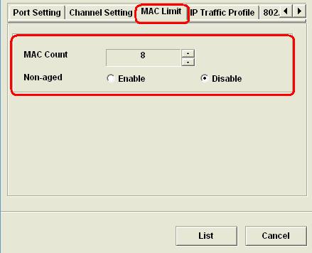
25 Step 9: Fast Provision (batch-configure) VC to VLAN port mapping Select L4, right click and navigate to ADSL > Fast Provision > Port & VC-to-VLAN. Please refer to screen shot below page 25
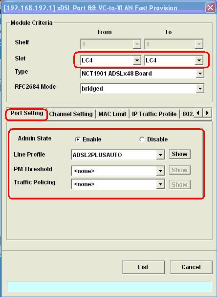

26 page 26


27 page 27

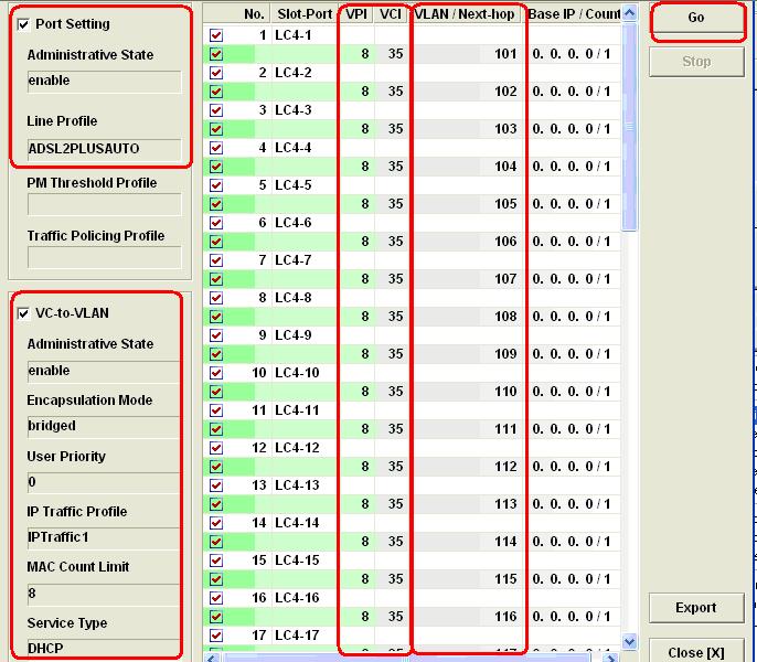
28 Please note that service type here is not applicable because in Step 4, the NCT1901 board initialisation indicates that the Service Type Control option was set to disabled. Click on List to list all the profiles and setting for LC4 from port 1 to port 48. You will then need to check whether all profiles are mapped correctly before batch configuration starts. page 28

29 Click on Go button to start batch configuration to line card 4. Once the profiles are pushed to the line card 4 s DSL ports, a green tick shown in the following screen shot will be displayed. page 29


30 Select L4, right click and navigate to Alarm > Alarm Syn to reflect the latest settings. page 30


31 The DSL ports in L4 have now turned yellow. This indicates that all of the 48 ports are now enabled. You will also notice that now the L4 s 48 DSL ports in the NCT192 physical panel are now doing its normal LED diagnosis flashing. Step 10: Configure trunk port of NCT192 DSLAM_A to the appropriate mode Select NC and navigate to Trunk > Port Setting. Please refer to screen shot below page 31


32 Select NC-GE2 and change the Admin state to enable and the port mode to subtended because NC-GE2 of NCT192_A will be used to connect to the NCT192_B GE1 uplink port for stacking purposes. Please refer to the following screen shots for references. In summary, the NCT192_A now has GE 1 set to uplink mode enabled and GE 2 set to subtended mode enabled. You will then select NC and navigate to Alarm > Alarm Sync to reflect the latest settings. The following operation window will be displayed and indicate the GE1 and GE2 are now enabled and configured to appropriate operation mode. page 32

33 Step 11: Configure SNMP manager IP Select NCT192 (NE) from the directory tree, right click and navigate to NE Management > NE Connection > SNMP Managers > add the management PC s IP address. The SNMP manager IP can be private IP address or public IP address. It represents the SNMP manager PC that has the NCT192 LCT installed. page 33
")


34 Step 12: Change SNMP Community Select NCT192 (NE) > NE Management > NE Connection > SNMP Community > add or modified SNMP communities. Please refer to screen shots below page 34

, right click and navigate to NE Management > NE")

35 Please then logout and log back into the NCT192 system with the SNMP community hotelmotel. Step 13: Change NCT192_A Secure Host IP Select NCT192 (NE), right click and navigate to NE Management > NE Connection > Secure Hosts > Modify Secure Host list from all to to 210. Please refer to screen shots below page 35
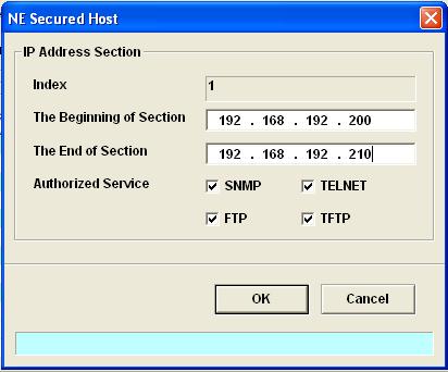

36 page 36


37 Step 14: Re-login with the new SNMP community and change the admin password to be different from the default one. The NCT192 administrator password is used in FTP and CLI/Telnet connection to the NCT192 IP DSLAM. Select NC card, right click and navigate to NE Management > NE Connection > NE User Account page 37


38 Step 15: Save the NCT192 NC Card system configuration page 38


39 Step 16: Save Line card configuration Step 17: Back up system configuration file locally page 39
40 The NCT192 has FTP server built in by default and it is enable. The default user name and password is admin/admin. The user name and password used in Part 1 is admin/admin123 as shown page 15. The NCT192 system configuration file can be backup locally through the LCT as shown above. The following message will be shown once Backup data successfully. Step 18: Test modem DSL Sync and data connectivity at NCT192_A IP DSLAM Now connect a test modem, the NB6+4W_R2T8 the bridged modem router to the line DSLAM tails of the NCT192_A. When a modem has DSL Sync with the IP DSLAM at port 1, the status LED light will turn green. When there is an active link to the GE1 of NCT192_A, the LED status light will turn green. Please see screen shot below. page 40


41 To see the DSL port trained status, select L4, right click and navigate to ADSL > Current Status > Port Rate Status page 41


42 To see the DSL port s learnt MAC address from the subscriber side, select L4, right click and navigate to ADSL > Current Status > Bridge Filtering Database page 42

43 To verify whether the DSL port 1 has passed on DHCP address to the subscriber side, select L4, right click and navigate to ADSL > Current Status > DHCP Session Information page 43


44 The DHCP Session Information List is now showing that LC4 port 1 VCI/VPI 8/35 has passed the DHCP address from the DHCP server at the uplink of the NCT192_A to the port s subscriber PC with IP address Since the NB6+4W_R2T8 is in bridged mode, the client MAC address that learnt, 00:08:0d: ba: 22:37 belongs to the subscriber s PC. Step 19: Login and configure NCT192_B Since most of the parameters and settings in NCT192_B will be the same as that in NCT192_A. Restore the system configuration file from A to B and make changes necessary. page 44

45 Logout and wait for approximately 5 to 6 min for the NCT192_B to complete system boot up. Once the NCT192_B completed system boot up, please verify connectivity to the Mgt IP address of NCT192_B before logging in via the LCT. page 45

46 Step 20: Re-login to NCT192_B and change the management IP address. Select the management IP address in the LCT directory tree and navigate to Modify NE and change the management IP address to /24. Please refer to screen shots below. page 46


47 Logout then re-login using the new NE NCT192 IP DSLAM IP address: page 47


48 Step 21: Modify NCT192_B uplink port setting Select NC, right click and navigate to Trunk > Port Setting > disabled the GE 2 as this port is not being used in NCT192_B. page 48


49 Once the GE 2 is disabled, the LED status will turn grey as shown below. page 49

50 Step 22: Save NCT192_B NC Card and LC card configuration. Step 23: Backup NCT192_B Configuration. Step 24: Test modem syn and data throughput in NCT192_B. Connect the Bridged NB6+4W_R2T8 to the line tails of the NCT192_B on LC 4 port 25; connect the GE1 of the NCT192_B to a network with DHCP server and navigate to Alarm Sync to refresh link status in the LCT. When you have a successful data throughput, the following stats will show in the Bridged Filtering Database under port 25 connection status. page 50
51 Since this NCT192_B system is connected to a DHCP server at its uplink, successful DHCP address assignment can be captured via port 25 pvc 8/35. Please refer to screen shot below Step 25: Connect NCT192_A and NCT192_B together & test data throughput At this stage, we have verified that when NCT192_A and NCT192_B connect the DHCP server individually, we received successful data throughput. You may now connect the GE 1 (uplink) of NCT192_B to the GE 2 (subtended) of NCT192_A, and make sure GE 1 (uplink) on the NCT192_A is connected to the DHCP server. Once connection is completed, you may now reset the NC card on NCT192_A by navigating to NE > Reset > to perform a system reboot so that new changes can take effect. After the NCT192_A has completed its system reboot, the subscriber PC at the NCT192_B port 25 pvc 8/35 will have IP address assigned successfully by the DHCP Sever. page 51

52 The steps and procedures for configuring two NCT192 IP DSLAMs in untagged mode for uni-cast application is now completed. The subscriber connected to the stacked NCT192 system has demonstrated successful data though put for untagged traffic. In Part 2 of this white paper, we will be looking at how to configure NCT192 IP DSLAMs to pass VLAN tagged packets in a stacked system. page 52
53 Part 2: How to stack NCT192 IP DSLAM in VLAN Tagged Mode Overview Part 2 describes the steps and procedure for configuring two NCT192 IP DSLAMs in VLAN tagged mode for uni-cast application. Part 2 of this white paper is built-upon the completion of Part 1 where the same ADSL profile and GE port mode settings will be used. You will notice that there is less number of steps involved because it is assumed that the configurations made in Part 1 were kept in the two IP DSLAMs. The only changes to be made to NCT192_A and B are the global VLAN mode and the DSL port s VC-to-VLAN configuration. The two NCT192 system used are stilled named NCT192_A and NCT192_B in this section. Figure 9 illustrates the logical network diagram used Part 2. There are a total of 14 steps described in part 2. The logical order of configuration described is as follows. Configure NCT192_B DSL and GE interface VLANs Test Modem data throughput from NCT192_A Configure NCT192_A DSL and GE interfaces VLANs Test Modem data throughput from NCT192_B Connect NCT192_B to NCT192_A Test Modem data throughput from NCT192_B Part 2 test complete It is generally recommended to start with the IP DSLAM that kept the least number of VLAN database and work its way up, hence the steps shown in this section are started with configuration in NCT192_B IP DSLAM. The following VLAN numbers are assigned to NCT192_B. LC4: Port 1 (VLAN 301), Port 2 (VLAN 302);... Port 48 (VLAN 348). GE 1: VLAN 301 to Q Tagged GE 2: (disabled) NC card: Tagged Mode The following VLAN numbers are assigned to NCT192_A LC4: Port 1 (VLAN 101), Port 2 (VLAN 102);... Port 48 (VLAN 148). GE 1: VLAN 101 to 148 VLAN Tagged; VLAN 301 to 348 (VLAN Tagged) GE 2: VLAN 101 to 148 VLAN Tagged; VLAN 301 to 348 (VLAN Tagged) NC card: Tagged Mode page 53

54 Logical Network Diagram Figure 9: Part 1 logical network diagram Stacking NCT192s in Tagged mode The following IP DSLAM IP address and device login details will be used in Part 2. NCT192_A Mgt: /24 NCT192_B Mgt: /24 (Default: /24) Mgt PC: /24 SNMP Manager IP in NCT192_A & NCT192_B: (Default: ) SNMP Manager Community in NCT192_A & NCT192_B: hotelmotel (Default: netman) User Name / Password in NCT192_A & NCT192_B: admin/admin123 (Default: admin/admin) NB6+4W_R2T8: Bridged mode page 54

55 Steps & Procedures Step1: Configure NCT192_B DSL port with VLANs. Verify connectivity to NCT192_B and login to via LCT Select L4 and navigate to ADSL > Fast Provision > Port & VC-to-VLAN > assignment DSL ports to different VLANs. Please refer screen shots below. page 55

56 Make the rest of the other parameter settings the same as shown in Part 1. Click on List to review all VC-to-VLAN settings. Click on Go to map the new profiles to the DSL ports. page 56

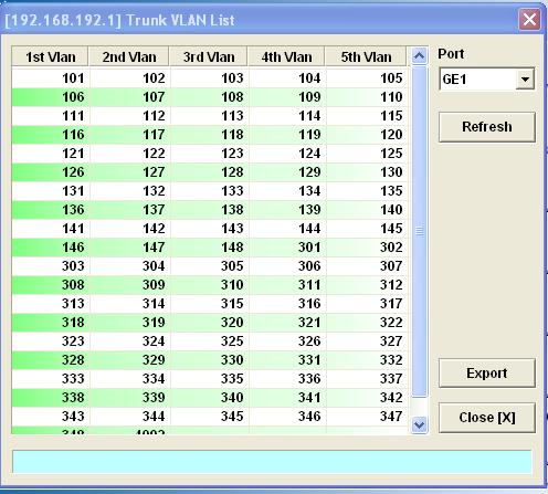
57 Step 2: Configure NCT192_B GE 1 port as trunk port for VLAN 301 to 348 Select NC card, right click and navigate to Trunk > Manual VLAN Setting > add VLANs to GE 1 trunk port. Please refer to screen shots shown below. page 57

58 Step 3: Configure NCT192_B NC card global mode to tagged mode Select NC, right click and navigate to Board Setting > Modify Tagged mode setting from Untaggedonly to Tagged-Only mode page 58


59 The system will now reboot. Please logout from the LCT and re-log in once the system completed system reboot after 5 to 6 minutes. Step 4: Re-log in to system and check VLAN status. To check GE ports VLAN table, select NC card, right click and navigate to Trunk > UGE VLAN Status. Step 5: Save NC card and LC card configuration. Step 6: Backup NCT192_B VLAN Tagged system configuration. page 59

60 Select NC, right click and navigate to NE Management > NE Backup & Restore > back up system configuration. The default FTP user name and password is admin/admin, since the FTP password has been changed in Part 1, the new password is used to performed system backup. Please refer to screen shot shown below. Step 7: Test modem data throughput in NCT192_B VLAN Tagged mode Connect the Bridged NB6+4W_R2T8 to the line tails of the NCT192_B on LC 4 port 25; connect the GE1 of the NCT192_B to a network with DHCP server and recognised VLAN 325 tagged packets. Please select L4, right click and navigate to Alarm > Alarm Syn to show the current NB6+4W_R2T8 modem status in the LCT. page 60
61 To view the MAC address learnt by port 25 PVC 8/35 on VLAN 325 in NCT192_B, select port 25, right click and navigate to ADSL > Current Status > Bridged Filtering Database To view the successful DHCP data throughput to LC 4, port 25 s subscriber side, select port 25, right click and navigate to ADSL > Current Status > DHCP Session Information page 61
62 Since the NB6+4W_R2T8 is a bridged mode modem that means the MAC-address 00:08:0d: ba: 22:37 is the subscriber PC on port LC4 port 25. The subscriber PC is assigned with an IP address of NCT192_B in now tested ok under VLAN tagged mode. In the next steps, we will be look at VLAN configuration in NCT192_A. Step 8: Assign NCT192_A DSL port to VLANs Verify connectivity to NCT192_A (IP address: and login to via LCT. Select L4, right click and navigate to ADSL > Fast Provision > Port & VC-to-VLAN > assignment DSL ports to different VLANs. Please refer to screen shots below. page 62

63 Make the rest of the other parameter settings the same as shown in Part 1. Click on List to review all VC-to-VLAN settings. Click on Go to map the new profiles to the DSL ports. page 63

64 page 64


65 Step 9: Configure NCT192_B NC card s global mode to tagged mode Select NC, right click and navigate to Board Setting > Modify Tagged mode setting from Untaggedonly to Tagged-Only. System NC card will now reboot. Generally takes 5 to 6 minutes once completed. page 65

66 The NCT192_A will now reboot, please logout of the NCT192_A LCT and re-login once the system completes reboot in 5 to 6 minutes. Verify NCT192_A mgt port s connectivity and login to LCT. Notice that NCT1902 is now in TAG mode. Please see screen shot shown as follows. Step 10: Configure NCT192_A GE 1 and GE 2 port as trunk port for VLAN101 to 148, VLAN 301 to 348 Select NC card and navigate to Trunk > Manual VLAN Setting > add VLANs to GE 1 trunk port. Please refer to screen shots shown below. page 66

67 To view NCT192_A GE1 and GE2 VLAN status, select NC card, right click and navigate to Trunk > UGE VLAN Status. page 67

68 page 68

69 Step 11: Save NC card and LC card configuration. Step 12: Backup NCT192_A VLAN Tagged system configuration. Step 13: Test modem data throughput in NCT192_A VLAN Tagged mode Connect the Bridged NB6+4W_R2T8 to the line tails of the NCT192_A on LC 4 port 1; connect the GE1 of the NCT192_A to a network with DHCP server and recognised VLAN 101 tagged packets. Please select L4, right click and navigate to Alarm > Alarm Syn to show the current NB6+4W_R2T8 modem status in the LCT. page 69


70 To view the MAC address learnt by port 1 PVC 8/35 on VLAN 101 in NCT192_A, select LC4 port 1, right click and navigate to ADSL > Current Status > Bridged Filtering Database To view the successful DHCP data throughput to LC 4, port 1 s subscriber side, select LC 4 port 1, right click and navigate to ADSL > Current Status > DHCP Session Information page 70
71 NCT192_A VLAN Tagged data throughput Tested ok. Step 14: Connect NCT192_A and NCT192_B together & test VLAN data throughput At this stage, we have verified that when NCT192_A and NCT192_B are both in VLAN tagged mode. When each of them connects to the DHCP server individually via VLAN-aware GE switch, we received successful data throughput. You may now connect the GE 1 (uplink) of NCT192_B to the GE 2 (subtended) of NCT192_A, and make sure GE 1 (uplink) of the NCT192_A is connected to the VLAN aware switch and the DHCP server/ip network. Once connection is completed, you may now reset the NC card on NCT192_A by navigating to NE > Reset > to perform a system reboot so that new changes can take effect. After the NCT192_A completed its system reboot, the subscriber PC at the NCT192_B port 25 pvc 8/35 will have IP address assigned successfully by the DHCP Server. page 71
72 The DHCP Session information List indicated that a successful DHCP address has assigned to LC 4, port 25 PVC 8/35 in VLAN 325. The MAC address of the subscriber PC (because bridged modem was used) is 00:08:0d:ba:22:37 and it is assigned with a IP address This concludes the procedures and testing for the two stacked NCT192 IP DSLAMs in VLAN tagged mode for uni-cast application. The subscriber/s connected to the stacked NCT192 system has demonstrated successful data throughput for untagged and VLAN tagged applications in Part 1 and Part 2. page 72
DSLAM using Port Location Mapping
 How to configure NetComm IAC3000 with NCT192 IP DSLAM using Port Location Mapping Introduction The following paper provides instructions on how to configure NetComm s IAC3000 Internet Access Controller
NCT240 IP DSLAM with IAC4500 VLAN Tagging Implementation
 NCT240 IP DSLAM with IAC4500 VLAN Tagging Implementation The NetComm NCT240 24 Port IP DSLAMs support 802.1Q VLAN Tagging. This white paper is written to help IP DSLAM system integrator to set up and configure
How to configure the IAC4500 Internet Access Controller for Billing by Volume Application with NCT480 IP DSLAM using port location mapping
 How to configure the IAC4500 Internet Access Controller for Billing by Volume Application with NCT480 IP DSLAM using port location mapping Introduction The following paper provides instructions on how
IP DSLAM IDM-168. To meet the increasing demand for high-speed internet access and triple play application service. The next generation
 IP DSLAM IDM-168 To meet the increasing demand for high-speed internet access and triple play application service. The next generation network offers a feasible functionality of integrated services with
Peplink SD Switch User Manual. Published on October 25th, 2018
 Peplink SD Switch User Manual Published on October 25th, 2018 1 Table of Contents Switch Layout 4 Specifications 5 Hardware Overview 6 Quick Start Functions 7 Reset Switch 7 Connect Ethernet 7 Connect
SWP-0208G, 8+2SFP. 8-Port Gigabit Web Smart Switch. User s Manual
 SWP-0208G 1 SWP-0208G, 8+2SFP 8-Port Gigabit Web Smart Switch User s Manual Version: 3.4 April 1, 2008 2 TABLE OF CONTENT 1.0 INTRODUCTION...4 1.1 MAIN FEATURES...4 1.2 START TO MANAGE THIS SWITCH...6
AT-S41 Version 1.1.7C Management Software for the AT-8326GB and AT-8350GB Series Fast Ethernet Switches. Software Release Notes
 AT-S41 Version 1.1.7C Management Software for the AT-8326GB and AT-8350GB Series Fast Ethernet Switches Software Release Notes Please read this document before you begin to use the AT-S41 management software.
Optical Line Terminal Equipment. Element Management System. User Manual
 Optical Line Terminal Equipment Element Management System User Manual Version 1.2 1 / 98 Thank you for choosing our products. Preface Revision History Version Revision date Revision Reason V 1.1 15/10/2015
Peplink SD Switch User Manual
 Peplink SD Switch User Manual Peplink Products: Peplink SD Switch 8-ports/24-ports/48-ports Peplink SD Switch Firmware 1.2.0 Published on December 10, 2018 Copyright & Trademarks Copyright & trademark
MTA_98-366_Vindicator930
 MTA_98-366_Vindicator930 Number: 98-366 Passing Score: 700 Time Limit: 45 min File Version: 1.0 http://www.gratisexam.com/ Microsoft Technology Associate Networking Fundamentals MTA 98-366 Exam A QUESTION
ProSAFE 8-Port 10-Gigabit Web Managed Switch Model XS708Ev2 User Manual
 ProSAFE 8-Port 10-Gigabit Web Managed Switch Model XS708Ev2 User Manual April 2016 202-11656-01 350 East Plumeria Drive San Jose, CA 95134 USA Support Thank you for purchasing this NETGEAR product. You
ProSAFE 8-Port and 16-Port 10-Gigabit Ethernet Web Managed Switch Models XS708Ev2 and XS716E User Manual
 ProSAFE 8-Port and 16-Port 10-Gigabit Ethernet Web Managed Switch Models XS708Ev2 and XS716E User Manual March 2017 202-11656-03 350 East Plumeria Drive San Jose, CA 95134 USA Support Thank you for purchasing
User s Manual ADSL Router Modem DB Ethernet Ports
 User s Manual ADSL Router Modem DB 120 4 Ethernet Ports 1. About ADSL ADSL (Asymmetric Digital Subscriber Line) is a technology that allows high-speed data to be transmitted over existing copper telephone
48-Port 10/100/1000BASE-T + 4-Port 100/1000BASE-X SFP Gigabit Managed Switch GS T4S
 48-Port 10/100/1000BASE-T + 4-Port 100/1000BASE-X SFP Gigabit Managed Switch GS-4210-48T4S Outlines Product Overview Product Benefits Applications Appendix Product Features 2 / 42 Product Overview Layer
BiPAC 7800VDP(O)X. Dual-band Wireless-N VoIP ADSL2+ (VPN) Router. Quick Start Guide
X. Dual-band Wireless-N VoIP ADSL2+ (VPN) Router. Quick Start Guide") BiPAC 7800VDP(O)X Dual-band Wireless-N VoIP ADSL2+ (VPN) Router Quick Start Guide Billion BiPAC 7800VDP(O)X Dual-band Wireless-N VoIP ADSL2+ (VPN) Router PLEASE READ THE QUICK START GUIDE AND FOLLOW THE
BiPAC 7800VDP(O)X Dual-band Wireless-N VoIP ADSL2+ (VPN) Router Quick Start Guide Billion BiPAC 7800VDP(O)X Dual-band Wireless-N VoIP ADSL2+ (VPN) Router PLEASE READ THE QUICK START GUIDE AND FOLLOW THE
Trademarks. Statement of Conditions by NETGEAR, Inc. All rights reserved.
 2004 by NETGEAR, Inc. All rights reserved. Trademarks @2004 NETGEAR, Inc. NETGEAR, the Netgear logo, The Gear Guy and Everybody s connecting are trademarks of Netgear, Inc. in the United States and/or
VLANs Level 3 Unit 9 Computer Networks
 VLANs Some Requirements of LANs Need to split up broadcast domains to make good use of bandwidth People in different departments may need to be grouped together for access to servers Security: restrict
Cisco Transport Controller Operation
 CHAPTER 8 This chapter describes Cisco Transport Controller (CTC), the software interface for the Cisco ONS 15454. For CTC set up and login information, refer to the Cisco ONS 15454 Procedure Guide. Chapter
Management Software AT-S101. User s Guide. For use with the AT-GS950/8POE Gigabit Ethernet WebSmart Switch. Version Rev.
 Management Software AT-S101 User s Guide For use with the AT-GS950/8POE Gigabit Ethernet WebSmart Switch Version 1.0.0 613-000985 Rev. A Copyright 2008 Allied Telesis, Inc. All rights reserved. No part
Configuration Guide Rev A
 B r o a d A c c e s s Configuration Guide 760-000728 Rev A BroadAccess Configuration Guide Table of Contents List of Figures v List of Tables x 1. Introduction 1 1.1. Related Publications 2 1.2. Conventions
Fibre Optic PTP Broadband Solution (FTTx)
") Fibre Optic PTP Broadband Solution (FTTx) March 2015 TNS COMMS Contents 1. High Level Architecture 2. Equipment being supplied by TNS 3. VLAN Design 4. Service Provisioning 5. Management 6. IP Addressing
Fibre Optic PTP Broadband Solution (FTTx) March 2015 TNS COMMS Contents 1. High Level Architecture 2. Equipment being supplied by TNS 3. VLAN Design 4. Service Provisioning 5. Management 6. IP Addressing
Coax Ethernet Managed Bridge Master
 Coax Ethernet Managed Bridge Master Quick Start Guide Version 1.1 Dec. 2009 Packing List The contents, One Main Unit (the Bridge) One DC 12V Power Adapter One F-Type Male-to-Male Coaxial Cable One RJ-45
VERTICAL HORIZON VH-2402S FAST ETHERNET SWITCH MANAGEMENT GUIDE
 VERTICAL HORIZON VH-2402S FAST ETHERNET SWITCH MANAGEMENT GUIDE 9033645-01 Notice Only qualified personnel should perform installation procedures. NOTICE Enterasys Networks reserves the right to make
RX3041. User's Manual
 RX3041 User's Manual Table of Contents 1 Introduction... 2 1.1 Features and Benefits... 3 1.2 Package Contents... 3 1.3 Finding Your Way Around... 4 1.4 System Requirements... 6 1.5 Installation Instruction...
Chapter 1 Getting Started with Switch Management
 Chapter 1 Getting Started with Switch Management This section provides an overview of switch management, including the methods you can choose to start managing your NETGEAR GS700TS Gigabit Stackable Smart
NF15ACV. VDSL/ADSL Dual Band AC1200 WiFi Gigabit Modem Router with VoIP. Firmware Release Notes
 NF15ACV VDSL/ADSL Dual Band AC1200 WiFi Gigabit Modem Router with VoIP Firmware Release Notes Copyright Copyright 2017 NetComm Wireless Limited. All rights reserved. The information contained herein is
BiPAC 7404VNOX BiPAC 7404VNPX
 BiPAC 7404VNOX BiPAC 7404VNPX 3G/ VoIP/ 802.11n ADSL2+ (VPN) Firewall Router Quick Start Guide Billion BiPAC 7404VNOX/7404VNPX 3G/VoIP/802.11n ADSL2+ (VPN) Firewall Router PLEASE READ THE QUICK START
Application Guide. Stacking XGS / XGS HP / XGS / XGS HP
 Application Guide Stacking XGS3700-24 / XGS3700-24HP / XGS3700-48 / XGS3700-48HP Index 1. Purpose of this Document.... 2 2. Scenario One: Stack two Switches... 3 2.1 Topology... 3 2.2 Application Scenario...
FOUR-PORT ADSL ROUTER. KD319MUI ADSL Router User Manual
 FOUR-PORT ADSL ROUTER KD319MUI ADSL Router User Manual NOTICE This document contains proprietary information protected by copyright, and this Manual and all the accompanying hardware, software, and documentation
Broadband Router. User s Manual
 Broadband Router User s Manual 1 Introduction... 4 Features... 4 Minimum Requirements... 4 Package Content... 4 Note... 4 Get to know the Broadband Router... 5 Back Panel... 5 Front Panel... 6 Setup Diagram...7
AXIS T85 PoE+ Network Switch Series. AXIS T8524 PoE+ Network Switch. AXIS T8516 PoE+ Network Switch. User Manual
 AXIS T8508 PoE+ Network Switch AXIS T8516 PoE+ Network Switch AXIS T8524 PoE+ Network Switch User Manual Table of Contents About this document........................................ 3 Solution overview...........................................
BiPAC 7800DX(L) Dual-Band Wireless-N 3G/4G LTE (VPN) ADSL2+ Router. Quick Start Guide
 Dual-Band Wireless-N 3G/4G LTE (VPN) ADSL2+ Router. Quick Start Guide") BiPAC 7800DX(L) Dual-Band Wireless-N 3G/4G LTE (VPN) ADSL2+ Router Quick Start Guide Quick Start Guide Billion BiPAC 7800DX(L) Dual-Band Wireless-N 3G/4G LTE (VPN) ADSL2+ Router PLEASE READ THE QUICK START
BiPAC 7800DX(L) Dual-Band Wireless-N 3G/4G LTE (VPN) ADSL2+ Router Quick Start Guide Quick Start Guide Billion BiPAC 7800DX(L) Dual-Band Wireless-N 3G/4G LTE (VPN) ADSL2+ Router PLEASE READ THE QUICK START
Overview of Ports and Interfaces
 Three concepts are key to understanding how controllers connect to a wireless network: ports, interfaces, and WLANs. Information About Ports, page 1 Information About Distribution System Ports, page 2
3COM 3M Certified Enterprise LAN Specialist Final v3.0. Download Full Version :
 3COM 3M0-212 Certified Enterprise LAN Specialist Final v3.0 Download Full Version : http://killexams.com/pass4sure/exam-detail/3m0-212 Which SuperStake 3 Switch 4900 model can concurrently support Gigabit
User Manual. GSS Series 16/24 Port Gigabit Web Managed Switch (GSS-16T4SFP & GSS-24T4SFP) Version 1.0 Sep. 2007
 Version 1.0 Sep. 2007") User Manual GSS Series 16/24 Port Gigabit Web Managed Switch (GSS-16T4SFP & GSS-24T4SFP) Version 1.0 Sep. 2007 1 Table of Contents CAUTION...3 ELECTRONIC EMISSION NOTICES...3 ABOUT THIS USER MANUAL...4
User Manual GSS Series 16/24 Port Gigabit Web Managed Switch (GSS-16T4SFP & GSS-24T4SFP) Version 1.0 Sep. 2007 1 Table of Contents CAUTION...3 ELECTRONIC EMISSION NOTICES...3 ABOUT THIS USER MANUAL...4
Deployment of a new M-Lab site
 Deployment of a new M-Lab site Deployment of a new M-Lab site Scope of the document HW deployment - on-site CHECKLIST for on-site staff, BEFORE going to the site SW configuration - on-site and off-site
BiPAC 7401V(G)PX. 3G/ VoIP/ (802.11g) ADSL2+ Firewall Router. Quick Start Guide
PX. 3G/ VoIP/ (802.11g) ADSL2+ Firewall Router. Quick Start Guide") BiPAC 7401V(G)PX 3G/ VoIP/ (802.11g) ADSL2+ Firewall Router Quick Start Guide Quick Start Guide Billion BiPAC 7401V(G)PX 3G/ VoIP/ (802.11g) ADSL2+ Firewall Router PLEASE READ THE QUICK START GUIDE AND
BiPAC 7401V(G)PX 3G/ VoIP/ (802.11g) ADSL2+ Firewall Router Quick Start Guide Quick Start Guide Billion BiPAC 7401V(G)PX 3G/ VoIP/ (802.11g) ADSL2+ Firewall Router PLEASE READ THE QUICK START GUIDE AND
IPLoC D2-POM - User Guide
 IPLoC D2-POM - User Guide Table of Content 3 Security Note 4 Quick Start Guide 5 Introduction 5 Overview 5 MoCA Coax Network - Example 6 Interface 7 Installing IPLoC D2-POM 7 Overview 7 Minimum installation
Peplink Balance Multi-WAN Routers
 Peplink Balance Multi-WAN Routers Model 20/30/210/310/380/390/580/710/1350 User Manual Firmware 5.1 September 10 Copyright & Trademarks Specifications are subject to change without prior notice. Copyright
Configuring the Catalyst 3920
 CHAPTER 5 Configuring the Catalyst 3920 You might not have to configure the Catalyst 3920 for it to work in your network; it is shipped with default configuration parameters and can function with these
SYSTEMS ADMINISTRATION USING CISCO (315)
") Page 1 of 10 Contestant Number: Time: Rank: SYSTEMS ADMINISTRATION USING CISCO (315) REGIONAL 2014 TOTAL POINTS (500) Failure to adhere to any of the following rules will result in disqualification: 1.
Page 1 of 10 Contestant Number: Time: Rank: SYSTEMS ADMINISTRATION USING CISCO (315) REGIONAL 2014 TOTAL POINTS (500) Failure to adhere to any of the following rules will result in disqualification: 1.
User Manual. WLAN ADSL2+ Router
 User Manual WLAN ADSL2+ Router INDEX 1.0 About This Manual... 1 1.1 Document Objectives... 1 1.2 Product Overview... 1 1.3 Product Description... 1 2.0 Specification... 2 2.1 LED Meaning... 3 2.2 Back
Value Added Services (VAS) Traffic Forwarding
 Traffic Forwarding") CHAPTER 12 Revised: June 27, 2011, Introduction This chapter provides an overview of VAS traffic forwarding, explaining what is it and how it works. It also explains the various procedures for configuring
CHAPTER 12 Revised: June 27, 2011, Introduction This chapter provides an overview of VAS traffic forwarding, explaining what is it and how it works. It also explains the various procedures for configuring
FOUR-PORT ADSL ROUTER. KD319RI ADSL Router User Manual
 FOUR-PORT ADSL ROUTER KD319RI ADSL Router User Manual NOTICE This document contains proprietary information protected by copyright, and this Manual and all the accompanying hardware, software, and documentation
Table of Contents 1 VLAN Configuration 1-1
 Table of Contents 1 VLAN Configuration 1-1 Overview 1-1 Introduction to VLAN 1-1 VLAN Fundamentals 1-2 Types of VLAN 1-3 Introduction to Port-Based VLAN 1-3 Configuring a VLAN 1-4 Configuration Task List
Interconnecting Cisco Networking Devices Part1 ( ICND1) Exam.
 Exam.") Cisco 640-822 Interconnecting Cisco Networking Devices Part1 ( ICND1) Exam TYPE: DEMO http://www.examskey.com/640-822.html Examskey Cisco 640-822 exam demo product is here for you to test quality of the
Cisco 640-822 Interconnecting Cisco Networking Devices Part1 ( ICND1) Exam TYPE: DEMO http://www.examskey.com/640-822.html Examskey Cisco 640-822 exam demo product is here for you to test quality of the
Using Cisco IOS Software
 APPENDIX A This appendix describes the basics about using the Cisco IOS software that is installed on every Cisco ubr905 and Cisco ubr925 cable access routers: Accessing the Command-Line Interface, page
Overview. About the Catalyst 2820 and Catalyst 1900 Switches CHAPTER
 CHAPTER 1 Overview This chapter describes the Enterprise Edition software features for Catalyst 2820 and Catalyst 1900 switches. It also describes the feature default settings and shows the management
BEC 8920AC Ultimum The Ultimate Residential Gateway with ac VDSL2/ADSL2+/Bonded/FTTH Quick Start Guide
 BEC 8920AC Ultimum The Ultimate Residential Gateway with 802.11ac VDSL2/ADSL2+/Bonded/FTTH Quick Start Guide BEC 8920AC The Ultimate Residential Gateway w/ 802.11ac PLEASE READ THE QUICK START GUIDE AND
Innovative Electronics for a Changing World INDEX
 Innovative Electronics for a Changing World INDEX 1. SYSTEM DESCRIPTION 2. BOARD CONNECTIONS terminals and indicators 3. CONNECTION DIAGRAM 4. START UP GUIDE and passwords 5. HOME PAGE 6. STATUS PAGE 7.
LAN Interface TCW120B
 LAN Interface TCW120B 1. Short description TCW120 is a multifunctional device for remote monitoring and management. It is an Ethernet based controller, which is designed to work in IP-based networks and
D-Link Central WiFiManager Configuration Guide
 Table of Contents D-Link Central WiFiManager Configuration Guide Introduction... 3 System Requirements... 3 Access Point Requirement... 3 Latest CWM Modules... 3 Scenario 1 - Basic Setup... 4 1.1. Install
8-Port Gigabit Ethernet Smart Managed Plus Switch with 2-Port 10G/Multi-Gig Uplinks User Manual
 8-Port Gigabit Ethernet Smart Managed Plus Switch with 2-Port 10G/Multi-Gig Uplinks User Manual Model GS110EMX December 2017 202-11810-03 350 E. Plumeria Drive San Jose, CA 95134 USA Support Thank you
8-Port 10/100/1000 Gigabit Switch. User Guide. with WebView WIRED SRW2008/SRW2008P/SRW2008MP. Model No.
 8-Port 10/100/1000 Gigabit Switch with WebView WIRED User Guide Model No. SRW2008/SRW2008P/SRW2008MP Copyright and Trademarks Specifications are subject to change without notice. Linksys is a registered
Cisco CCT Routing & Switching
 Cisco - CCT Routing & Switching 1 QUESTION: 1 Which router can be used for disk-in-access to the router CLI management purposes and does not usually pass normal network traffic? A. AUX B. Gigabit Ethernet
Key Features... 2 Known Issues... 3 Resolved Issues... 5 Upgrading SonicOS Enhanced Image Procedures... 6 Related Technical Documentation...
 SonicOS Notes Contents Key Features... 2 Known Issues... 3 Resolved Issues... 5 Upgrading SonicOS Enhanced Image Procedures... 6 Related Technical Documentation... 9 Platform Compatibility The SonicOS
Overview. Switch Features CHAPTER
 CHAPTER 1 Overview The 2900 XL series switches are workgroup Ethernet switches that supply autosensing 10BaseT or 100BaseT connections on all ports. Expansion slots on Catalyst 2912MF XL and 2924M XL switches
ZyWALL 70. Internet Security Appliance. Quick Start Guide Version 3.62 December 2003
 ZyWALL 70 Internet Security Appliance Quick Start Guide Version 3.62 December 2003 Introducing the ZyWALL The ZyWALL 70 is the ideal secure gateway for all data passing between the Internet and the LAN.
DAS-3 Series Rev.C. Before You Begin. Check Your Package Contents
 DAS-3 Series Rev.C ADSL IP DSLAM Before You Begin This Quick Installation Guide gives step-by-step instructions for setting up the D-Link DAS-3 Series ADSL IP DSLAM. This Quick Installation Guide only
I-Fly Wireless Broadband Router
 with 4 Fast Ethernet ports + 1 Wan port Quick Start Guide A02-WR-54G/G2 (November 2003)V1.00 For more detailed instructions on configuring and using the I- Storm Lan Router ADSL, please refer to the online
1. Which OSI layers offers reliable, connection-oriented data communication services?
 CCNA 1 Practice Final Exam Answers v4.0 100% 1. Which OSI layers offers reliable, connection-oriented data communication services? application presentation session transport network 2. Refer to the exhibit.
FOUR-PORT ADSL ROUTER. KD319EUI ADSL Router User Manual
 FOUR-PORT KD319EUI ADSL Router User Manual NOTICE This document contains proprietary information protected by copyright, and this Manual and all the accompanying hardware, software, and documentation are
Hotwire DSL Access System Student Guide MCP Card. GranDSLAM & MCP Card. Revision Paradyne Corporation Page 1
 Hotwire DSL Access System Student Guide MCP Card GranDSLAM & MCP Card Revision 4.1 2003 Paradyne Corporation Page 1 MCP Card Student Guide Hotwire DSL Access System Phone: 800-257-5033 Fax: 727-530-8270
CHAPTER 7 ADVANCED ADMINISTRATION PC
 ii Table of Contents CHAPTER 1 INTRODUCTION... 1 Broadband ADSL Router Features... 1 Package Contents... 3 Physical Details... 4 CHAPTER 2 INSTALLATION... 6 Requirements... 6 Procedure... 6 CHAPTER 3 SETUP...
Chapter 6: Network Layer
 Chapter 6: Network Layer CCNA Routing and Switching Introduction to Networks v6.0 Chapter 6 - Sections & Objectives 6.1 Network Layer Protocols Explain how network layer protocols and services support
Configuring VLANs. Finding Feature Information. Prerequisites for VLANs
 Finding Feature Information, page 1 Prerequisites for VLANs, page 1 Restrictions for VLANs, page 2 Information About VLANs, page 2 How to Configure VLANs, page 7 Monitoring VLANs, page 19 Where to Go Next,
User Handbook. Switch Series. Default Login Details. Version 1.0 Edition
 User Handbook Switch Series Zyxel GS1920 / GS2210 / XGS2210 / GS3700 / XGS3700 / XGS4600 / XS1920 / XS3700 Default Login Details LAN IP Address https://192.168.1.1 User Name admin Password 1234 Version
Preserve 802.1Q Tagging with 802.1P Marking over ATM PVCs for xdsl Uplinks
 Preserve 802.1Q Tagging with 802.1P Marking over ATM PVCs for xdsl Uplinks First Published: October 21, 2009 Last Updated: Sept 17, 2010 The Preserve 802.1Q Tagging with 802.1P Marking over ATM PVCs for
User Manual ES-5808PHG. Gigabit 8-Port 802.3at PoE Web Smart Switch
 User Manual ES-5808PHG Gigabit 8-Port 802.3at PoE Web Smart Switch Content Content I Introduction..3 Product Overview.3 Web Management Feature.3 Specification..4 Mechanical...4 Performance...5 Package
Multi-Homing Broadband Router. User Manual
 Multi-Homing Broadband Router User Manual 1 Introduction... 4 Features... 4 Minimum Requirements... 4 Package Content... 4 Note... 4 Get to know the Broadband Router... 5 Back Panel... 5 Front Panel...
Management Software AT-S79. User s Guide. For use with the AT-GS950/16 and AT-GS950/24 Smart Switches. Version Rev.
 Management Software AT-S79 User s Guide For use with the AT-GS950/16 and AT-GS950/24 Smart Switches Version 1.0.0 613-000207 Rev. A Copyright 2005 Allied Telesyn, Inc. All rights reserved. No part of this
Paradyne Student Guide GranDSLAM 4.X. GranDSLAM 4.X. Revision Paradyne Corporation Page 1
 Paradyne Student Guide GranDSLAM 4.X GranDSLAM 4.X Revision 1.0 2004 Paradyne Corporation Page 1 GranDSLAM 4.X Student Guide Paradyne Phone: 800-257-5033 Fax: 727-530-8270 Address: 8545 126 th Avenue North
DC-228. ADSL2+ Modem/Router. User Manual. -Annex A- Version: 1.0
 DC-228 ADSL2+ Modem/Router -Annex A- User Manual Version: 1.0 TABLE OF CONTENTS 1 PACKAGE CONTENTS...3 2 PRODUCT LAYOUT...4 3 NETWORK + SYSTEM REQUIREMENTS...6 4 DC-228 PLACEMENT...6 5 SETUP LAN, WAN...7
VigorAccess IP DSLAM. Quick Start Guide. Version: 1.0 Date: 2006/05/22
 VigorAccess IP DSLAM Quick Start Guide Version: 1.0 Date: 2006/05/22 VigorAccess IP DSLAM Quick Start Guide This quick start guide will guide you to finish the basic configuration for accessing Internet
CCNA. Course Catalog
 CCNA Course Catalog 2012-2013 This course is intended for the following audience: Network Administrator Network Engineer Systems Engineer CCNA Exam Candidates Cisco Certified Network Associate (CCNA 640-802)
28 Port Fiber Gigabit with 10G SFP+ Management Switch
 28 Port Fiber Gigabit with 10G SFP+ Management Switch ES220-28-24F Gigabit Fiber applies in longer distance for Surveillance, Enterprise, Campuses and Data Centers To meet the backbone application of surveillance,
Product Overview. Product Overview. Product Specifications. Ordering Information. Service Scenario for PON Interface Layout Operating Status LEDs
 Product Overview Service Scenario for PON Interface Layout Operating Status LEDs Product Specifications Capabilities Physical Specifications Ordering Information Product Overview The H665 is Optical Network
LevelOne GES GE with 1 Combo SFP Web Smart Switch User Manual
 LevelOne GES-0852 8 GE with 1 Combo SFP Web Smart Switch User Manual Version 1.0-1109 1 FCC Certifications This Equipment has been tested and found to comply with the limits for a Class A digital device,
2.4GHz 300Mbps 11b/g/n 29dBm AP/Router/WDS Bridge/WDS AP/WDS station/cb/cr/up. Software Features System Requirement. Status
 is a 300Mbps wireless-n multi-function gigabit AP/CB which offers unlimited coverage, strong penetration, secure network management and 802.3af PoE connection. Package Contents - 1* - 1*12V/1A Power Adapter
User Manual. ADSL2+ Combo Router
 User Manual ADSL2+ Combo Router INDEX 1.0 About This Manual...1 1.1 Document Objectives...1 1.2 Product Overview...1 1.3 Product Description...1 2.0 Specification...2 2.1 LED Meaning...3 2.2 Back Panel
IES-5106M. Support Notes. Integrated Ethernet Switch. June 2011 Edition 1.0
 IES-5106M Integrated Ethernet Switch Support Notes June 2011 Edition 1.0 Content General Application Notes... 3 The comparison of IES serious models... 4 Cable wiring... 6 Key Application Scenario... 10
IPA-48S/IPA-24S. User Manual. Version 1.1 RECYCLABLE
 IPA-48S/IPA-24S User Manual Version 1.1 RECYCLABLE Contents: WARNING INSTRUCTIONS... 2 1 Introduction... 3 1.1 IPA-48S/IPA-24S Overview... 3 1.2 Application... 3 1.3 Specification... 4 2 Hardware Setup
Configuring Interface Characteristics
 Finding Feature Information, page 1 Information About, page 1 How to Configure Interface Characteristics, page 11 Monitoring Interface Characteristics, page 28 Configuration Examples for Interface Characteristics,
About Chassis Manager
 CHAPTER 1 Chassis Manager runs directly on your Server Switch to perform administration tasks. This chapter discusses the various components of the interface. Chassis Manager runs on all Server Switches.
DSL/CABLE ROUTER with PRINT SERVER
 USER S MANUAL DSL/CABLE ROUTER with PRINT SERVER MODEL No:SP888BP http://www.micronet.info 1 Content Table CHAPTER 0:INTRODUCTION... 4 FEATURES... 4 MINIMUM REQUIREMENTS... 4 PACKAGE CONTENT... 4 GET TO
Create a pfsense router for your private lab network template
 Create a pfsense router for your private lab network template Some labs will require a private network where you can deploy services like DHCP. Here are instructions for setting up an uplink router for
Index. Numerics. Index p priority (QoS) definition Q VLAN standard w as a region 5-54
 definition Q VLAN standard w as a region 5-54") Index Numerics 802.1p priority (QoS) 802.1Q VLAN standard 5-7 802.1w as a region 5-54 A active path 5-5 address IP 7-8 advertisement 3-3 applicable products 1-ii ARP age setting 7-10 cache 7-4 cache table
Index Numerics 802.1p priority (QoS) 802.1Q VLAN standard 5-7 802.1w as a region 5-54 A active path 5-5 address IP 7-8 advertisement 3-3 applicable products 1-ii ARP age setting 7-10 cache 7-4 cache table
Conettix ITS-D6686-INTL
 Conettix ITS-D6686-INTL EN Installation Guide Ethernet Network Adapter Conettix ITS-D6686-INTL Installation Guide Contents Contents 1.0 Introduction... 3 1.1 Network Interface... 3 1.2 Serial Interface...
FEATURES HARDWARE CONNECTION
 1 FEATURES 1. Support ANSI T1.413 ISSUE 2, ITU G.992.1 (G.DMT), ITU G.992.2 (G.LITE), ITU G992.3, ITU G992.5 2. Web-based configuration and monitoring. 3. Support multiple PVCs. 4. Routing function. 5.
IPS-3106 SERIES Managed Industrial PoE Ethernet Switch
 IPS-3106 SERIES Managed Industrial PoE Ethernet Switch Network Management User s Manual Version 0.96 1 Trademarks Contents are subject to revision without prior notice. All other trademarks remain the
LevelOne. User Manual. 11g Wireless ADSL2+ Modem Router WBR Ver. 1.0
 LevelOne User Manual WBR-3601 11g Wireless ADSL2+ Modem Router Ver. 1.0 Table of Contents Product Overview... 3 Product Description... 3 Specification... 4 LED Meaning... 6 Back Panel Connectors... 7 Factory
Overview of the Cisco Service Control Value Added Services Feature
 CHAPTER 1 Overview of the Cisco Service Control Value Added Services Feature Revised: May 27, 2013, Introduction The VAS feature enables the Cisco SCE platform to access an external expert system for classification
BiPAC 8501 R3/ 8521 R3
 BiPAC 8501 R3/ 851 R3 SHDSL.bis Firewall Bridge/ Router Quick Start Guide Quick Start Guide Billion BiPAC 8501 R3/ 851 R3 SHDSL.bis Firewall Bridge/Router For more detailed instructions on configuring
KD216 VDSL Router User Manual
 KD216 VDSL Router NOTICE This document contains proprietary information protected by copyright, and this Manual and all the accompanying hardware, software, and documentation are copyrighted. All rights
User Guide. Unmanaged Pro Switch TL-SG105E/TL-SG108E/TL-SG116E REV4.0.1
 User Guide Unmanaged Pro Switch TL-SG105E/TL-SG108E/TL-SG116E 1910012413 REV4.0.1 May 2018 CONTENTS About This Guide Intended Readers... 1 Conventions... 1 More Information... 1 Introduction Product Overview...
Interfaces for Firepower Threat Defense
 This chapter includes Firepower Threat Defense interface configuration including Ethernet settings, EtherChannels, VLAN subinterfaces, IP addressing, and more. About Firepower Threat Defense Interfaces,
EMS System For IP DSLAM. User Manual
 EMS System For IP DSLAM User Manual Document #: ST-208004003 Issue3.0 Date: May 6, 2010 Copyright@2009 by Shanghai Sino-Telecom Communication Technology Co. Ltd. All Rights Reserved No part of this document
BiPAC 8200M. BiPAC 8200N
 BiPAC 8200M VDSL2 Modem BiPAC 8200N Wireless-N VDSL2 Firewall Router Quick Start Guide Billion BiPAC 8200M VDSL2 Modem/ BiPAC 8200N Wireless-N VDSL2 Firewall Router PLEASE READ THE QUICK START GUIDE
ECB N Multi-Function Gigabit Client Bridge
 ECB9500 is a powerful and multi-functioned 11n product with 7 major multi-functions, is designed to operate in every working environment for enterprises. ECB9500 is a Wireless Network device that delivers
IES Support Notes
 IES-5000 Support Notes Oct 2006 INDEX Application Notes...3 Setting up different DSL port speeds to different subscribers...3 Configuring 802.1Q VLAN...7 Triple play Application...9 802.1x Application...