Web Configuration Tool Guide
|
|
|
- Jonas McCoy
- 6 years ago
- Views:
Transcription
 www.blackbox.com info@blackbox.")
1 LIG1014A LIE1014A Industrial Managed Gigabit Ethernet Switch Web Configuration Tool Guide Contact Information Order toll-free in the U.S. or for FREE 24/7 technical support: Call BBOX (outside U.S. call )
2 Trademarks Used in this Manual Black Box and the Double Diamond logo are registered trademarks of BB Technologies, Inc. Any other trademarks mentioned in this manual are acknowledged to be the property of the trademark owners. Disclaimer: Black Box Network Services shall not be liable for damages of any kind, including, but not limited to, punitive, consequential or cost of cover damages, resulting from any errors in the product information or specifications set forth in this document and Black Box Network Services may revise this document at any time without notice blackbox.com
3 Table of Contents 1. Overview System Description Using the Web Interface Web Browser Support Navigation Title Bar Icons Ending a Session Using the Online Help Using the Web Login Tree View Configuration Menu Monitor Menu Diagnostics Menu Maintenance Menu Configuration System System Information System IP System NTP System Time System Log System Alarm Profile Port Power Savings Port DHCP Server Mode DHCP Server Excluded IP DHCP Server Pool DHCP Snooping DHCP Relay Users Privilege Level Auth Method SSH HTTPS Access Management SNMP System Configuration SNMP Trap Configuration SNMP Communities SNMP Users SNMP Groups SNMP Views SNMP Access RMON Statistics RMON History RMON Alarm RMON Event Limit Control blackbox.com
4 NAS ACL Port ACL Rate Limiters Access Control List IP Source Guard IP Source Guard Configuration IP Source Guard Static Table ARP Inspection VLAN Configuration Static Table Dynamic Table RADIUS TACACS Static Aggregation LACP Aggregation Loop Protection Spanning Tree Bridge Settings MSTI Mapping MSTI Priorities CIST Ports MSTI Ports IPMC Profile Profile Table Address Entry MVR IPMC IGMP Snooping Basic Configuration VLAN Configuration Port Filtering Profile MLD Snooping Basic Configuration VLAN Configuration Port Filtering Profile LLDP LLDP-MED MAC Table VLANs Private VLANs Membership Port Isolation VCL MAC-based VLAN Protocol-based VLAN Protocol to Group Group to VLAN IP Subnet-based VLAN Voice VLAN Voice VLAN Configuration Voice VLAN OUI blackbox.com
5 QoS Port Classification Port Policing Port Scheduler Port Shaping Port Tag Remarking Port DSCP DSCP-Based QoS DSCP Translation DSCP Classification QoS Control List Storm Control Mirror GVR Global Config Port Config sflow RingV DDMI Monitor System System Information CPU Load IP Status System Log System Detailed Log System Alarm Green Ethernet Port Power Saving Ports Ports State Traffic Overview QoS Statistics QCL Status Detailed Statistics DHCP DHCP Server Statistics Binding Declined IP DHCP Snooping Table DHCP Relay Statistics DHCP Detailed Statistics Security Accessment Management Statistics Network Port Security Switch Port NAS Switch Port blackbox.com
6 ACL Status ARP Inspection IP Source Guard AAA RADIUS Overview RADIUS Details Switch RMON Statistics History Alarm Event LACP System Status Port Status Port Statistics Loop Protection Spanning Tree Bridge Status Port Status Port Statistics MVR MVR Statistics MVR Channel Groups MVR SFM Information IPMC IGMP Snooping IGMP Snooping Status Groups Information IPv4 SFM Information MLD Snooping MLD Snooping Status Groups Information IPv6 SFM Information LLDP Neighbors LLDP-MED Neighbors EEE Port Statistics MAC Table VLANs VLANs Membership VLANs Ports VCL MAC-Based VLAN sflow Ring DDMI Overview DDMI Detailed Diagnostics Ping Page blackbox.com
7 2.5.2 Ping VeriPHY Maintenance Restart Device Factory Default Software Software Upload Image select Configuration Save startup-config Download Upload Activate Delete blackbox.com Page 7
8 Industrial Managed Gigabit Ethernet Switch Web Tool Configuration Guide 1. Overview 1.1 System Description The Industrial Managed Gigabit Ethernet Switch delivers high quality, wide operating temperature range, extended power input range, IP-30 design, and advanced VLAN and QoS features. It s ideal for harsh environments and mission critical applications. Managed QoS LIG1014A/LIE1014A provides enterprise-class networking features to fulfill the needs of large network infrastructure and extreme environments. LIG1014A/LIE1014A eases the effort to build a network infrastructure that offers a reliable, well managed and good QoS networking for any business requiring continuous and well-protected services in managed environments. With features such as Fast Failover ring protection and QoS, customers can ensure their network will support real-time and high-quality applications. 1.2 Using the Web Interface This document LIG1014A/LIE1014A Web Configuration Tool Guide describes the switch s web management feature and design layout, and explains how to use the web interface Web Browser Support IE 7 (or newer version) with the following default settings is recommended: Language script Latin based Web page font Times New Roman Plain text font Courier New Encoding Unicode (UTF-8) Text size Medium Firefox with the following default settings is recommended: Web page font Times New Roman Encoding Unicode (UTF-8) Text size 16 Google Chrome with the following default settings is recommended: Web page font Times New Roman Encoding Unicode (UTF-8) 8
9 Industrial Managed Gigabit Ethernet Switch Web Tool Configuration Guide Text size Medium Navigation You can reach all main screens of the web interface by clicking on hyperlinks in the four menu boxes on the left side of the screen: Ø Configuration Ø Monitor Ø Diagnostics Ø Maintenance Title Bar Icons Help Button For more information about any screen, click on the Help button on the screen. Help information is displayed in the same window. Save Button If any unsaved change has been made to the configuration (by you during this or a prior session, or by any other administrator using the web interface or the Command Line Interface), a Save icon appears in the title line. To save the running configuration to the startup configuration: 1. Click on the Save icon. The System/Save and Restore screen appears. 2. Click on Submit next to Data Control Action drop-down list on top of System/Save and Restore screen Ending a Session To end a session, close your web browser. This prevents an unauthorized user from accessing the system using your user name and password. 1.3 Using the Online Help Each screen has a Help button that invokes a page of information relevant to the particular screen. The Help is displayed in a new window. Each web page of Configuration/Status/System functions has a corresponding help page. 9
10 Industrial Managed Gigabit Ethernet Switch Web Tool Configuration Guide 2. Using the Web 2.1 Login Operation Field Username Password 1. Type in the Username and Password. 2. Click Sign in. Description Login user name. The maximum length is 32. Default: admin Login user password. The maximum length is 32. Default: none 10

11 Industrial Managed Gigabit Ethernet Switch Web Tool Configuration Guide 2.2 Tree View The tree view is a web menu. Use it to view the page for data or configuration Configuration Menu 11


12 Industrial Managed Gigabit Ethernet Switch Web Tool Configuration Guide Monitor Menu Diagnostics Menu 12

13 Industrial Managed Gigabit Ethernet Switch Web Tool Configuration Guide Maintenance Menu 13

14 Industrial Managed Gigabit Ethernet Switch Web Tool Configuration Guide 2.3 Configuration System System Information The switch system information is provided here. Object System Contact Description The textual identification of the contact person for this managed node, together with information on how to contact this person. The allowed string length is 0 to 255, and the allowed content is ASCII characters from 32 to 126. System Name An administratively assigned name for this managed node. By convention, this is the node's fully-qualified domain name. A domain name is a text string drawn from the alphabet (A-Z, a-z), digits (0-9), minus sign (-). No space characters are permitted as part of a name. The first character must be an alpha character. The first or last character must not be a minus sign. The allowed string length is 0 to 255. System Location The physical location of this node (e.g., telephone closet, 3rd floor). The allowed string length is 0 to 255, and the allowed content is ASCII characters from 32 to

15 Industrial Managed Gigabit Ethernet Switch Web Tool Configuration Guide Buttons Click to save changes. Click to revert to previously saved values System IP Configure IP basic settings, control IP interfaces and IP routes. The maximum number of interfaces supported is 8 and the maximum number of routes is
16 Industrial Managed Gigabit Ethernet Switch Web Tool Configuration Guide Object Description IP Configuration Mode Configure whether the IP stack should act as a Host or a Router. In Host mode, IP traffic between interfaces will not be routed. In Router mode, traffic is routed between all interfaces. DNS Server This setting controls the DNS name resolution done by the switch. The following modes are supported: From any DHCP interfaces The first DNS server offered from a DHCP lease to a DHCP-enabled interface will be used. No DNS server No DNS server will be used. Configured Explicitly provide the IP address of the DNS Server in dotted decimal notation. From this DHCP interface Specify from which DHCP-enabled interface a provided DNS server should be preferred. DNS Proxy When DNS proxy is enabled, system will relay DNS requests to the currently configured DNS server, and reply as a DNS resolver to the client devices on the network. IP Interfaces Delete VLAN Select this option to delete an existing IP interface. The VLAN associated with the IP interface. Only ports in this VLAN will be able to access the IP interface. This field is only available for input when creating a new interface. IPv4 DHCP Enabled Enable the DHCP client by checking this box. If this option is enabled, the system will configure the IPv4 address and mask of the interface using the DHCP protocol. The DHCP client will announce the configured System Name as hostname to provide DNS lookup. IPv4 DHCP Fallback Timeout The number of seconds for trying to obtain a DHCP lease. After this period expires, a configured IPv4 address will be used as IPv4 interface address. A value of zero disables the fallback mechanism, so that DHCP will keep retrying until a valid lease is obtained. Legal values are 0 to seconds. 16
17 Industrial Managed Gigabit Ethernet Switch Web Tool Configuration Guide IPv4 DHCP Current Lease For DHCP interfaces with an active lease, this column shows the current interface address, as provided by the DHCP server. IPv4 Address The IPv4 address of the interface in dotted decimal notation. If DHCP is enabled, this field configures the fallback address. The field may be left blank if IPv4 operation on the interface is not desired or no DHCP fallback address is desired. IPv4 Mask The IPv4 network mask, in number of bits (prefix length). Valid values are between 0 and 30 bits for an IPv4 address. If DHCP is enabled, this field configures the fallback address network mask. The field may be left blank if IPv4 operation on the interface is not desired or no DHCP fallback address is desired. IPv6 Address The IPv6 address of the interface. An IPv6 address is a 128-bit record represented as eight fields of up to four hexadecimal digits with a colon separating each field (:). For example, fe80::215:c5ff:fe03:4dc7. The symbol :: is a special syntax that can be used as a shorthand way of representing multiple 16-bit groups of contiguous zeros, but it can appear only once. It can also represent a legally valid IPv4 address. For example, :: The field may be left blank if IPv6 operation on the interface is not desired. IPv6 Mask The IPv6 network mask, in number of bits (prefix length). Valid values are between 1 and 128 bits for an IPv6 address. The field may be left blank if IPv6 operation on the interface is not desired. IP Routes Delete Network Select this option to delete an existing IP route. The destination IP network or host address of this route. Valid format is dotted decimal notation or a valid IPv6 notation. A default route can use the value or IPv6 :: notation. Mask Length The destination IP network or host mask, in number of bits (prefix length). It defines how much of a network address that must match, in order to qualify for this route. Valid values are between 0 and 32 bits respectively, 128 for IPv6 routes. Only a default route will have a mask length of 0 (it will match anything). Gateway The IP address of the IP gateway. Valid format is dotted decimal notation or a valid IPv6 notation. Gateway and Network must be of the same type. 17
18 Industrial Managed Gigabit Ethernet Switch Web Tool Configuration Guide Next Hop VLAN(Only for IPv6) The VLAN ID (VID) of the specific IPv6 interface associated with the gateway. The given VID ranges from 1 to 4094 and will be effective only when the corresponding IPv6 interface is valid. If the IPv6 gateway address is link-local, it must specify the next hop VLAN for the gateway. If the IPv6 gateway address is not link-local, the system ignores the next hop VLAN for the gateway. 18
19 Industrial Managed Gigabit Ethernet Switch Web Tool Configuration Guide Buttons Click to add a new IP interface. A maximum of 8 interfaces is supported. Click to add a new IP route. A maximum of 32 routes is supported. Click to save changes. Click to revert to previously saved values. 19

20 Industrial Managed Gigabit Ethernet Switch Web Tool Configuration Guide System NTP Configure NTP on this page. Object Description Mode Indicates the NTP mode operation. Possible modes are: Enabled: Enable NTP client mode operation. Disabled: Disable NTP client mode operation. Server # Provide the IPv4 or IPv6 address of a NTP server. IPv6 address is a 128-bit record represented as eight fields of up to four hexadecimal digits with a colon separating each field (:). For example, 'fe80::215:c5ff:fe03:4dc7'. The symbol '::' is a special syntax that can be used as a shorthand way of representing multiple 16-bit groups of contiguous zeros, but it can appear only once. It can also represent a legally valid IPv4 address. For example, ':: '. 20
21 Industrial Managed Gigabit Ethernet Switch Web Tool Configuration Guide Buttons Click to save changes. Click to undo any changes made locally and revert to previously saved values. 21
22 Industrial Managed Gigabit Ethernet Switch Web Tool Configuration Guide System Time This page allows you to configure the Time Zone. Time Zone Configuration Time Zone Acronym Daylight Saving Time Configuration Daylight Saving Time Start time settings Week Day Month Hours Minutes End time settings Week Day Month Hours Minutes Offset settings Offset Start time setting Month Date Year Hours Minutes End time settings Month Date Lists various Time Zones worldwide. Select the appropriate Time Zone from the drop-down list and click Save to set. User can set the acronym of the time zone. This is a user-configurable acronym to identify the time zone. Range: Up to 16 characters) This is used to set the clock forward or backward according to the configurations set below for a defined Daylight Saving Time duration. Select 'Disable' to disable the Daylight Saving Time configuration. Select 'Recurring' and configure the Daylight Saving Time duration to repeat the configuration every year. Select 'Non-Recurring' and configure the Daylight Saving Time duration for single time configuration. (Default : Disabled) Recurring Configurations Select the starting week number. Select the starting day. Select the starting month. Select the starting hour. Select the starting minute. Select the ending week number. Select the ending day. Select the ending month. Select the ending hour. Select the ending minute. Enter the number of minutes to add during Daylight Saving Time. (Range: 1 to 1440) Non Recurring Configurations Select the starting month. Select the starting date. Select the starting year. Select the starting hour. Select the starting minute. Select the ending month. Select the ending date. 22
23 Industrial Managed Gigabit Ethernet Switch Web Tool Configuration Guide Year Hours Minutes Select the ending year. Select the ending hour. Select the ending minute Offset settings Offset Enter the number of minutes to add during Daylight Saving Time. (Range: 1 to 1440) Date/Time Configuration Date/Time Settings Year Year of current date time. (Range: 2000 to 2037) Month Date Hours Minutes Seconds Month of current date time. Date of current date time. Hour of current date time. Minute of current date time. Second of current date time. Buttons Click to save changes. Click to undo any changes made locally and revert to previously saved values. 23

24 Industrial Managed Gigabit Ethernet Switch Web Tool Configuration Guide System Log Configure System Log on this page. Object Server Mode Description Indicates the server mode operation. When the mode operation is enabled, the syslog message will be sent out to the syslog server. The syslog protocol is based on UDP communication and received on UDP port 514. The syslog server will not send acknowledgments back to the sender, since UDP is a connectionless protocol and does not provide acknowledgments. The syslog packet will always be sent out, even if the syslog server does not exist. Possible modes are: Enabled: Enable server mode operation. Disabled: Disable server mode operation. Server Address Syslog Level Indicates the IPv4 host address of the syslog server. If the switch provides a DNS feature, it also can be a host name. Indicates what kind of message will be sent to the syslog server. Possible modes are: Info: Send information, warnings, and errors. Warning: Send warnings and errors. Error: Send errors. 24
25 Industrial Managed Gigabit Ethernet Switch Web Tool Configuration Guide Buttons Click to save changes. Click to undo any changes made locally and revert to previously saved values. 25

26 Industrial Managed Gigabit Ethernet Switch Web Tool Configuration Guide System Alarm Profile Alarm Profile is provided here to enable/disable alarms. Object Description ID Description Enabled The identification of the Alarm Profile entry. Alarm Type Description. If alarm entry is Enabled, then the alarm will be shown in alarm history/current when it occurs. Alarm LED will be on (lit); Alarm Relay will also be enabled. SNMP trap will be sent if any SNMP trap entry exists and is enabled. Disabled If alarm entry is Disabled, the alarm will not be captured/shown in the alarm history/current when an alarm occurs; it will not trigger the Alarm LED change, Alarm Relay, and SNMP trap. NOTE: When any alarm exists, the Alarm LED will be on (lit); Alarm Output Relay will also be enabled. 26
27 Industrial Managed Gigabit Ethernet Switch Web Tool Configuration Guide Buttons Click to save changes. Click to undo any changes made locally and revert to previously saved values. 27

28 Industrial Managed Gigabit Ethernet Switch Web Tool Configuration Guide Port Power Savings This page allows the user to configure the port power savings features. Object Description Port Power Savings Configuration Optimize EEE for The switch can be set to optimize EEE for either best power saving or least traffic latency. Port Configuration Port The switch port number of the logical port. ActiPHY Link down power savings enabled. ActiPHY works by lowering the power for a port when there is no link. The port is powered up for short moment to determine if a cable is inserted. PerfectReach Cable length power savings enabled. PerfectReach works by determining the cable length and lowering the power for ports with short cables. 28
29 Industrial Managed Gigabit Ethernet Switch Web Tool Configuration Guide EEE Controls whether EEE is enabled for this switch port. For maximizing power savings, the circuit isn't started when transmit data is ready for a port, but is instead queued until a burst of data is ready to be transmitted. This will give some traffic latency. If desired, you can minimize the latency for specific frames by mapping the frames to a specific queue (done with QOS), and then marking the queue as an urgent queue. When an urgent queue gets data to be transmitted, the circuits will be powered up at once and the latency will be reduced to the wakeup time. EEE Urgent Queues Queues set will activate transmission of frames as soon as data is available. Otherwise, the queue will postpone transmission until a burst of frames can be sent transmitted. Buttons Click to save changes. Click to undo any changes made locally and revert to previously saved values. 29

30 Industrial Managed Gigabit Ethernet Switch Web Tool Configuration Guide Port This page displays current port configurations. Ports can also be configured here. Object Description Port Link This is the logical port number for this row. The current link state is displayed graphically. Green indicates the link is up and red Indicates that it is down. Current Link Speed Configured Link Speed Provides the current link speed of the port. Selects any available link speed for the given switch port. Only speeds supported by the specific port are shown. Possible speeds are: Disabled - Disables the switch port operation. Auto - Port auto-negotiates speed with the link partner and selects the highest speed that is compatible with the link partner. 10Mbps HDX - Forces the copper port in 10-Mbps half-duplex mode. 10Mbps FDX - Forces the copper port in 10-Mbps full-duplex mode. 100Mbps HDX - Forces the copper port in 100-Mbps half-duplex mode. 100Mbps FDX - Forces the copper port in 100-Mbps full-duplex mode. 1Gbps FDX - Forces copper port in 1-Gbps full-duplex mode. 30
31 Industrial Managed Gigabit Ethernet Switch Web Tool Configuration Guide Flow Control When Auto Speed is selected on a port, this section indicates the flow control capability that is advertised to the link partner. When a fixed-speed setting is selected, that is what is used. The Current Rx column indicates whether pause frames on the port are obeyed, and the Current Tx column indicates whether pause frames on the port are transmitted. The Rx and Tx settings are determined by the result of the last Auto-Negotiation. Check the configured column to use flow control. This setting is related to the setting for Configured Link Speed. Maximum Frame Size Excessive Collision Mode Enter the maximum frame size allowed for the switch port, including FCS. Configure port transmit collision behavior. Discard: Discard frame after 16 collisions (default). Restart: Restart back off algorithm after 16 collisions. Buttons Click to save changes. Click to undo any changes made locally and revert to previously saved values. Click to refresh the page. Any changes made locally will be undone DHCP Server Mode This page configures global mode and VLAN mode to enable/disable DHCP server per system and per VLAN. 31

32 Industrial Managed Gigabit Ethernet Switch Web Tool Configuration Guide 32
33 Industrial Managed Gigabit Ethernet Switch Web Tool Configuration Guide Object Description Global Mode Mode Configure the operation mode per system. Possible modes are: Enabled: Enable DHCP server per system. Disabled: Disable DHCP server pre system. VLAN Mode VLAN Range Indicate the VLAN range in which DHCP server is enabled or disabled. The first VLAN ID must be smaller than or equal to the second VLAN ID. But, if the VLAN range contains only 1 VLAN ID, then you can just input it into either one of the first and second VLAN ID or both. On the other hand, if you want to disable existed VLAN range, then you can follow the steps listed below. 1. Press to add a new VLAN range. 2. Input the VLAN range that you want to disable. 3. Choose Mode to be Disabled. 4. Press to apply the change. 5. You will see that the disabled VLAN range is removed from the DHCP Server mode configuration page. 6. Press to add a new VLAN range. 7. Input the VLAN range that you want to disable. 8. Choose Mode to be Disabled. 9. Press to apply the change. 10. You will see the disabled VLAN range is removed from the DHCP Server mode configuration page. Mode Indicate the operation mode per VLAN. Possible modes are: Enabled: Enable DHCP server per VLAN. Disabled: Disable DHCP server pre VLAN. Buttons Click to delete the setting. Click to add a new VLAN range. Click to save changes. 33

34 Industrial Managed Gigabit Ethernet Switch Web Tool Configuration Guide Click to undo any changes made locally and revert to previously saved values DHCP Server Excluded IP This page configures excluded IP addresses. A DHCP server will not allocate these excluded IP addresses to a DHCP client. Object Description IP Range Define the IP range to be excluded IP addresses. The first excluded IP must be smaller than or equal to the second excluded IP. But, if the IP range contains only 1 excluded IP, then you can just input it to either one of the first and second excluded IP addresses or both. Buttons Click to delete the setting. Click to add a new excluded IP range. Click to save changes. 34

35 Industrial Managed Gigabit Ethernet Switch Web Tool Configuration Guide Click to undo any changes made locally and revert to previously saved values DHCP Server Pool This page manages DHCP pools. According to the DHCP pool, DHCP server will allocate IP address and deliver configuration parameters to DHCP client. Object Description Name Configure the pool name that accepts all printable characters, except white space. If you want to configure detailed settings, you can click the pool name to go into the configuration page. Type Display the type of pool. Network: the pool defines a pool of IP addresses to service more than one DHCP client. Host: the pool services for a specific DHCP client identified by client identifier or hardware address. If "-" is displayed, it means not defined. IP Display network number of the DHCP address pool. If "-" is displayed, it means not defined. Subnet Mask Display subnet mask of the DHCP address pool. If "-" is displayed, it means not defined. Lease Time Display lease time of the pool. s Click to delete the setting. 35
36 Industrial Managed Gigabit Ethernet Switch Web Tool Configuration Guide Click to add a new DHCP pool. Click to save changes. Click to undo any changes made locally and revert to previously saved values DHCP Snooping Configure DHCP Snooping on this page. 36

37 Industrial Managed Gigabit Ethernet Switch Web Tool Configuration Guide 37

38 Industrial Managed Gigabit Ethernet Switch Web Tool Configuration Guide Object Snooping Mode Description Indicates the DHCP snooping mode operation. Possible modes are: Enabled: Enable DHCP snooping mode operation. When DHCP snooping mode operation is enabled, the DHCP request messages will be forwarded to trusted ports and only allow reply packets from trusted ports. Disabled: Disable DHCP snooping mode operation. Port Mode Configuration Indicates the DHCP snooping port mode. Possible port modes are: Trusted: Configures the port as trusted source of the DHCP messages. Untrusted: Configures the port as untrusted source of the DHCP messages. Buttons Click to save changes. Click to undo any changes made locally and revert to previously saved values DHCP Relay A DHCP relay agent is used to forward and to transfer DHCP messages between the clients and the server when they are not in the same subnet domain. It stores the incoming interface IP address in the GIADDR field of the DHCP packet. The DHCP server can use the value of GIADDR field to determine the assigned subnet. For this condition, make sure the switch s VLAN interface IP address and PVID (Port VLAN ID) correctly. 38
39 Industrial Managed Gigabit Ethernet Switch Web Tool Configuration Guide Relay Mode Object Indicates the DHCP relay mode operation. Description Possible modes are: Enabled: Enable DHCP relay mode operation. When DHCP relay mode operation is enabled, the agent forwards and transfers DHCP messages between the clients and the server when they are not in the same subnet domain. And the DHCP broadcast message won't be flooded for security considerations. Disabled: Disable DHCP relay mode operation. Relay Server Relay Information Mode Indicates the DHCP relay server IP address. Indicates the DHCP relay information mode option operation. The option 82 circuit ID format is "[vlan_id][module_id][port_no]". The first four characters represent the VLAN ID, the fifth and sixth characters are the module ID (in a standalone device it always equals 0, in stackable device it means switch ID), and the last two characters are the port number. For example, " " means the DHCP message is received from VLAN ID 3, switch ID 1, port No 8. And option 82 remote ID value is equal to the switch MAC address. Possible modes are: Enabled: Enable DHCP relay information mode operation. When DHCP relay information mode operation is enabled, the agent inserts specific information (option 82) into a DHCP message when forwarding to a DHCP server and removes it from a DHCP message when transferring to a DHCP client. It only works when DHCP relay operation mode is enabled. Disabled: Disable DHCP relay information mode operation. Relay Server Indicates the DHCP relay server IP address. 39
40 Industrial Managed Gigabit Ethernet Switch Web Tool Configuration Guide Relay Information Mode Indicates the DHCP relay information mode option operation. The option 82 circuit ID format is "[vlan_id][module_id][port_no]". The first four characters represent the VLAN ID, the fifth and sixth characters are the module ID (in a standalone device it always equals 0, in a stackable device it equals the switch ID), and the last two characters are the port number. For example, " " means the DHCP message is received from VLAN ID 3, switch ID 1, port No 8. And the option 82 remote ID value is equal to the switch MAC address. Possible modes are: Enabled: Enable DHCP relay information mode operation. When DHCP relay information mode operation is enabled, the agent inserts specific information (option 82) into a DHCP message when forwarding to DHCP server and removes it from a DHCP message when transferring to DHCP client. It only works when DHCP relay operation mode is enabled. Disabled: Disable DHCP relay information mode operation. Relay Information Policy Indicates the DHCP relay information option policy. When DHCP relay information mode operation is enabled, if the agent receives a DHCP message that already contains relay agent information, it will enforce the policy. The 'Replace' policy is invalid when relay information mode is disabled. Possible policies are: Replace: Replace the original relay information when a DHCP message that already contains it is received. Keep: Keep the original relay information when a DHCP message that already contains it is received. Drop: Drop the package when a DHCP message that already contains relay information is received. Buttons Click to save changes. Click to undo any changes made locally and revert to previously saved values Users This page provides an overview of the current users. Currently, the only way to login as another user on the web server is to close and reopen the browser. 40

41 Industrial Managed Gigabit Ethernet Switch Web Tool Configuration Guide User Name Object Description A string identifying the user name that this entry should belong to. The allowed string length is 1 to 31. The valid user name allows letters, numbers, and underscores. Password The password of the user. The allowed string length is 0 to 31. Any printable characters, including space, are accepted. Privilege Level The privilege level of the user. The allowed range is 1 to 15. If the privilege level value is 15, it can access all groups, i.e. that is granted the fully control of the device. But other values need to refer to each group privilege level. User's privilege should be same or greater than the group privilege level to have the access of that group. By default setting, most groups privilege level 5 has read-only access and privilege level 10 has read-write access. And the system maintenance (software upload, factory defaults, and etc.) need user privilege level 15. Generally, the privilege level 15 can be used for an administrator account, privilege level 10 for a standard user account, and privilege level 5 for a guest account. Buttons Click to add a new user. Click to save changes. Click to undo any changes made locally and revert to previously saved values. Click to undo any changes made locally and return to the Users. Delete the current user. This button is not available for new configurations. (Add new user.) 41
42 Industrial Managed Gigabit Ethernet Switch Web Tool Configuration Guide 42

43 Industrial Managed Gigabit Ethernet Switch Web Tool Configuration Guide Privilege Level This page provides an overview of the privilege levels. 43
44 Industrial Managed Gigabit Ethernet Switch Web Tool Configuration Guide Object Group Name Description The name identifying the privilege group. In most cases, a privilege level group consists of a single module (e.g. LACP, RSTP, or QoS), but a few of them contain more than one. The following description defines these privilege level groups in detail: System: Contact, Name, Location, Timezone, Daylight Saving Time, Log. Security: Authentication, System Access Management, Port (contains Dot1x port, MAC based and the MAC Address Limit), ACL, HTTPS, SSH, ARP Inspection, IP source guard. IP: Everything except 'ping'. Port: Everything except 'VeriPHY'. Diagnostics: 'ping' and 'VeriPHY'. Maintenance: CLI- System Reboot, System Restore Default, System Password, Configuration Save, Configuration Load and Firmware Load. Web- Users, Privilege Levels and everything in Maintenance. Debug: Only present in CLI. Privilege Levels Every group has an authorization Privilege level for the following sub groups: configuration read-only, configuration/execute read-write, status/statistics read-only, status/statistics read-write (e.g. for clearing of statistics). User Privilege should be same or greater than the authorization Privilege level to have the access to that group. Buttons Click to save changes. Click to undo any changes made locally and revert to previously saved values. 44

45 Industrial Managed Gigabit Ethernet Switch Web Tool Configuration Guide Auth Method This page allows you to configure how a user is authenticated when he logs into the switch via one of the management client interfaces. Object Description Client Methods The management client for which the configuration below applies. Method can be set to one of the following values: no: Authentication is disabled and login is not possible. local: Use the local user database on the switch for authentication. radius: Use remote RADIUS server(s) for authentication. tacacs+: Use remote TACACS+ server(s) for authentication. Methods that involves remote servers are timed out if the remote servers are offline. In this case, the next method is tried. Each method is tried from left to right and continues until a method either approves or rejects a user. If a remote server is used for primary authentication, we recommend that you configure secondary authentication as 'local'. This will enable the management client to login via the local user database if none of the configured authentication servers are alive. Buttons Click to save changes. Click to undo any changes made locally and revert to previously saved values. 45


46 Industrial Managed Gigabit Ethernet Switch Web Tool Configuration Guide SSH Configure SSH on this page. Object Description Mode Indicates the SSH mode operation. Possible modes are: Enabled: Enable SSH mode operation. Disabled: Disable SSH mode operation. Buttons Click to save changes. Click to undo any changes made locally and revert to previously saved values HTTPS Configure HTTPS on this page. 46
47 Industrial Managed Gigabit Ethernet Switch Web Tool Configuration Guide Object Description Mode Indicates the HTTPS mode operation. When the current connection is HTTPS, to apply HTTPS disabled mode, operation will automatically redirect web browser to an HTTP connection. Possible modes are: Enabled: Enable HTTPS mode operation. Disabled: Disable HTTPS mode operation. Automatic Redirect Indicates the HTTPS redirect mode operation. It only significant if HTTPS mode "Enabled" is selected. Automatically redirects web browser to an HTTPS connection when both HTTPS mode and Automatic Redirect are enabled. Possible modes are: Enabled: Enable HTTPS redirect mode operation. Disabled: Disable HTTPS redirect mode operation. Buttons Click to save changes. Click to undo any changes made locally and revert to previously saved values Access Management Configure the access management table on this page. The maximum number of entries is 16. If the application's type matches any one of the access management entries, it will allow access to the switch. Object Description 47

48 Industrial Managed Gigabit Ethernet Switch Web Tool Configuration Guide Mode Indicates the access management mode operation. Possible modes are: Enabled: Enable access management mode operation. Disabled: Disable access management mode operation. Delete VLAN ID Start IP address End IP address HTTP/HTTPS Check to delete the entry. It will be deleted during the next save. Indicates the VLAN ID for the access management entry. Indicates the start IP address for the access management entry. Indicates the end IP address for the access management entry. Indicates that the host can access the switch from HTTP/HTTPS interface if the host IP address matches the IP address range provided in the entry. SNMP Indicates that the host can access the switch from SNMP interface if the host IP address matches the IP address range provided in the entry. TELNET/SSH Indicates that the host can access the switch from TELNET/SSH interface if the host IP address matches the IP address range provided in the entry. Buttons Click to add a new access management entry. Click to save changes. Click to undo any changes made locally and revert to previously saved values SNMP System Configuration Configure SNMP on this page. 48
49 Industrial Managed Gigabit Ethernet Switch Web Tool Configuration Guide Object Description Mode Indicates the SNMP mode operation. Possible modes are: Enabled: Enable SNMP mode operation. Disabled: Disable SNMP mode operation. Version Indicates the SNMP supported version. Possible versions are: SNMP v1: Set SNMP supported version 1. SNMP v2c: Set SNMP supported version 2c. SNMP v3: Set SNMP supported version 3. Read Community Indicates the community read access string to permit access to an SNMP agent. The allowed string length is 0 to 255, and the allowed content is the ASCII characters from 33 to 126. The field is applicable only when the SNMP version is SNMPv1 or SNMPv2c. If the SNMP version is SNMPv3, the community string will be associated with SNMPv3 communities table. It is more flexible to configure a security name than a SNMPv1 or SNMPv2c community string. In addition to community string, you can use a particular range of source addresses to restrict source subnet. Write Community Engine ID Indicates the community write access string to permit access to SNMP agent. The allowed string length is 0 to 255, and the allowed content is the ASCII characters from 33 to 126. The field is applicable only when SNMP version is SNMPv1 or SNMPv2c. If SNMP version is SNMPv3, the community string will be associated with SNMPv3 communities table. It is more flexible to configure security name than a SNMPv1 or SNMPv2c community string. In addition to community string, you can use a particular range of source addresses to restrict source subnet. Indicates the SNMPv3 engine ID. The string must contain an even number (in hexadecimal format) with number of digits between 10 and 64, but all-zeros and all-'f's are not allowed. Change of the Engine ID will clear all original local users. Buttons Click to save changes. Click to undo any changes made locally and revert to previously saved values. 49
50 Industrial Managed Gigabit Ethernet Switch Web Tool Configuration Guide SNMP Trap Configuration Configure SNMP trap on this page. Object Description Global Settings Mode Indicates the trap mode operation. Possible modes are: Trap Destination Configurations Enabled: Enable SNMP trap mode operation. Disabled: Disable SNMP trap mode operation. Name Enable Indicates the trap Configuration's name. Indicates the trap destination's name. Indicates the trap destination mode operation. Possible modes are: Enabled: Enable SNMP trap mode operation. Disabled: Disable SNMP trap mode operation. Version Indicates the SNMP trap supported version. Possible versions are: SNMPv1: Set SNMP trap supported version 1. SNMPv2c: Set SNMP trap supported version 2c. SNMPv3: Set SNMP trap supported version 3. 50
51 Industrial Managed Gigabit Ethernet Switch Web Tool Configuration Guide Destination Address Indicates the SNMP trap destination address. It allow a valid IP address in dotted decimal notation ('x.y.z.w'). It also allows a valid hostname. A valid hostname is a string drawn from the alphabet (A-Z, a-z), digits (0-9), dot (.), dash (-). Spaces are not allowed, the first character must be an alpha character, and the first and last characters must not be a dot or a dash. Indicates the SNMP trap destination IPv6 address. IPv6 address is in 128-bit records represented as eight fields of up to four hexadecimal digits with a colon separating each field (:). For example, 'fe80::215:c5ff:fe03:4dc7'. The symbol '::' is a special syntax that can be used as a shorthand way of representing multiple 16-bit groups of contiguous zeros; but it can appear only once. It can also represent a legally valid IPv4 address. For example, ':: '. Destination port Indicates the SNMP trap destination port. SNMP Agent will send SNMP message via this port, the port range is 1~

52 Industrial Managed Gigabit Ethernet Switch Web Tool Configuration Guide The SNMP Trap Configuration page includes the following fields: Object Description Trap Mode Indicates the SNMP trap mode operation. Possible modes are: Enabled: Enable SNMP trap mode operation. Disabled: Disable SNMP trap mode operation. Trap Version Indicates the SNMP trap supported version. Possible versions are: SNMP v1: Set SNMP trap supported version 1. SNMP v2c: Set SNMP trap supported version 2c. SNMP v3: Set SNMP trap supported version 3. Trap Community Indicates the community access string when sending SNMP trap packet. The allowed string length is 0 to 255, and the allowed content is ASCII characters from 33 to
53 Industrial Managed Gigabit Ethernet Switch Web Tool Configuration Guide Trap Destination Address Indicates the SNMP trap destination address. It allow a valid IP address in dotted decimal notation ('x.y.z.w'). And it also allow a valid hostname. A valid hostname is a string drawn from the alphabet (A-Za-z), digits (0-9), dot (.), dash (-). Spaces are not allowed, the first character must be an alpha character, and the first and last characters must not be a dot or a dash. Trap Destination IIPv6 Address Indicates the SNMP trap destination IPv6 address. IPv6 address is in 128-bit records represented as eight fields of up to four hexadecimal digits with a colon separating each field (:). For example, 'fe80::215:c5ff:fe03:4dc7'. The symbol '::' is a special syntax that can be used as a shorthand way of representing multiple 16-bit groups of contiguous zeros; but it can appear only once. It can also represent a legally valid IPv4 address. For example, ':: '. Trap Authentication Failure Indicates that the SNMP entity is permitted to generate authentication failure traps. Possible modes are: Enabled: Enable SNMP trap authentication failure. Disabled: Disable SNMP trap authentication failure. Trap Link-up and Link-down Indicates the SNMP trap link-up and link-down mode operation. Possible modes are: Enabled: Enable SNMP trap link-up and link-down mode operation. Disabled: Disable SNMP trap link-up and link-down mode operation. Trap Inform Mode Indicates the SNMP trap inform mode operation. Possible modes are: Enabled: Enable SNMP trap inform mode operation. Disabled: Disable SNMP trap inform mode operation. Trap Inform Timeout Indicates the SNMP trap inform timeout. The allowed range is 0 to (seconds) Trap Inform Retry Times Indicates the SNMP trap inform retry times. The allowed range is 0 to 255. Trap Probe Security Engine ID Indicates the SNMP trap probe security engine ID mode of operation. Possible values are: Enabled: Enable SNMP trap probe security engine ID mode of operation. Disabled: Disable SNMP trap probe security engine ID mode of operation. Trap Security Engine ID Indicates the SNMP trap security engine ID. SNMPv3 sends traps and informs using USM for authentication and privacy. A unique engine ID for these traps and informs is needed. When "Trap Probe Security Engine ID" is enabled, the ID will be probed automatically. Otherwise, the ID specified in this field is used. The string must contain an even number(in hexadecimal format) with number of digits between 10 and 64, but all-zeros and all-'f's are not allowed. 53
54 Industrial Managed Gigabit Ethernet Switch Web Tool Configuration Guide Trap Security Name Indicates the SNMP trap security name. SNMPv3 traps and informs using USM for authentication and privacy. A unique security name is needed when traps and informs are enabled. 54

55 Industrial Managed Gigabit Ethernet Switch Web Tool Configuration Guide Buttons Click to add a new user. Click to save changes. Click to undo any changes made locally and revert to previously saved values SNMP Communities Configure SNMPv3 community table on this page. The entry index key is Community. Object Description Delete Community Check to delete the entry. It will be deleted during the next save. Indicates the community access string to permit access to SNMPv3 agent. The allowed string length is 1 to 32, and the allowed content is ASCII characters from 33 to 126. The community string will be treated as security name and map a SNMPv1 or SNMPv2c community string. Source IP Indicates the SNMP access source address. A particular range of source addresses can be used to restrict source subnet when combined with source mask. Source Mask Indicates the SNMP access source address mask. 55

56 Industrial Managed Gigabit Ethernet Switch Web Tool Configuration Guide Buttons Click to add a new community entry. Click to save changes. Click to undo any changes made locally and revert to previously saved values SNMP Users Configure SNMPv3 user table on this page. The entry index keys are Engine ID and User Name. Object Description Delete Engine ID Check to delete the entry. It will be deleted during the next save. An octet string identifying the engine ID that this entry should belong to. The string must contain an even number(in hexadecimal format) with number of digits between 10 and 64, but all-zeros and all-'f's are not allowed. The SNMPv3 architecture uses the User-based Security Model (USM) for message security and the View-based Access Control Model (VACM) for access control. For the USM entry, the usmuserengineid and usmusername are the entry's keys. In a simple agent, usmuserengineid is always that agent's own snmpengineid value. The value can also take the value of the snmpengineid of a remote SNMP engine with which this user can communicate. In other words, if user engine ID equal system engine ID then it is local user; otherwise it's remote user. User name A string identifying the user name that this entry should belong to. The allowed string length is 1 to 32, and the allowed content is ASCII characters from 33 to
57 Industrial Managed Gigabit Ethernet Switch Web Tool Configuration Guide Security Level Indicates the security model that this entry should belong to. Possible security models are: NoAuth, NoPriv: No authentication and no privacy. Auth, NoPriv: Authentication and no privacy. Auth, Priv: Authentication and privacy. The value of security level cannot be modified if entry already exists. That means it must first be ensured that the value is set correctly. Authentication Protocol Indicates the authentication protocol that this entry should belong to. Possible authentication protocols are: None: No authentication protocol. MD5: An optional flag to indicate that this user uses MD5 authentication protocol. SHA: An optional flag to indicate that this user uses SHA authentication protocol. The value of security level cannot be modified if entry already exists. That means must first ensure that the value is set correctly. Authentication Password A string identifying the authentication password phrase. For MD5 authentication protocol, the allowed string length is 8 to 32. For SHA authentication protocol, the allowed string length is 8 to 40. The allowed content is ASCII characters from 33 to 126. Privacy Protocol Indicates the privacy protocol that this entry should belong to. Possible privacy protocols are: None: No privacy protocol. DES: An optional flag to indicate that this user uses DES authentication protocol. AES: An optional flag to indicate that this user uses AES authentication protocol. Privacy Password A string identifying the privacy password phrase. The allowed string length is 8 to 32, and the allowed content is ASCII characters from 33 to 126. Buttons Click to add a new user entry. Click to save changes. Click to undo any changes made locally and revert to previously saved values. 57

58 Industrial Managed Gigabit Ethernet Switch Web Tool Configuration Guide SNMP Groups Configure SNMPv3 group table on this page. The entry index keys are Security Model and Security Name. Object Description Delete Security Model Check to delete the entry. It will be deleted during the next save. Indicates the security model that this entry should belong to. Possible security models are: v1: Reserved for SNMPv1. v2c: Reserved for SNMPv2c. usm: User-based Security Model (USM). Security Name A string identifying the security name that this entry should belong to. The allowed string length is 1 to 32, and the allowed content is ASCII characters from 33 to 126. Group Name A string identifying the group name that this entry should belong to. The allowed string length is 1 to 32, and the allowed content is ASCII characters from 33 to 126. Buttons Click to add a new group entry Click to save changes. Click to undo any changes made locally and revert to previously saved values. 58

59 Industrial Managed Gigabit Ethernet Switch Web Tool Configuration Guide SNMP Views Configure SNMPv3 view table on this page. The entry index keys are View Name and OID Subtree. Object Description Delete View Name Check to delete the entry. It will be deleted during the next save. A string identifying the view name that this entry should belong to. The allowed string length is 1 to 32, and the allowed content is ASCII characters from 33 to 126. View Type Indicates the view type that this entry should belong to. Possible view types are: included: An optional flag to indicate that this view subtree should be included. excluded: An optional flag to indicate that this view subtree should be excluded. In general, if a view entry's view type is 'excluded', there should be another view entry existing with view type as 'included' and it's OID subtree should overstep the 'excluded' view entry. OID Subtree The OID defining the root of the subtree to add to the named view. The allowed OID length is 1 to 128. The allowed string content is digital number or asterisk(*). Buttons Click to add a new view entry. Click to save changes. Click to undo any changes made locally and revert to previously saved values. 59
60 Industrial Managed Gigabit Ethernet Switch Web Tool Configuration Guide 60

61 Industrial Managed Gigabit Ethernet Switch Web Tool Configuration Guide SNMP Access Configure SNMPv3 access table on this page. The entry index keys are Group Name, Security Model and Security Level. Object Description Delete Group Name Check to delete the entry. It will be deleted during the next save. A string identifying the group name that this entry should belong to. The allowed string length is 1 to 32, and the allowed content is ASCII characters from 33 to 126. Security Model Indicates the security model that this entry should belong to. Possible security models are: any: Any security model accepted(v1 v2c usm). v1: Reserved for SNMPv1. v2c: Reserved for SNMPv2c. usm: User-based Security Model (USM). Security Level Indicates the security model that this entry should belong to. Possible security models are: NoAuth, NoPriv: No authentication and no privacy. Auth, NoPriv: Authentication and no privacy. Auth, Priv: Authentication and privacy. Read View Name The name of the MIB view defining the MIB objects for which this request may request the current values. The allowed string length is 1 to 32, and the allowed content is ASCII characters from 33 to 126. Write View Name The name of the MIB view defining the MIB objects for which this request may potentially set new values. The allowed string length is 1 to 32, and the allowed content is ASCII characters from 33 to

62 Industrial Managed Gigabit Ethernet Switch Web Tool Configuration Guide Buttons Click to add a new access entry. Click to save changes. Click to undo any changes made locally and revert to previously saved values RMON Statistics Configure RMON Statistics table on this page. The entry index key is ID. Object Description Delete Check to delete the entry. It will be deleted during the next save. ID Indicates the index of the entry. The range is from 1 to Data Source Indicates the port ID which wants to be monitored. If in stacking switch, the value must add 1000*(switch ID-1), for example, if the port is switch 3 port 5, the value is 2005 Buttons Click to add a new community entry. Click to save changes. Click to undo any changes made locally and revert to previously saved values. 62

63 Industrial Managed Gigabit Ethernet Switch Web Tool Configuration Guide RMON History Configure RMON History table on this page. The entry index key is ID. Object Description Delete Check to delete the entry. It will be deleted during the next save. ID Indicates the index of the entry. The range is from 1 to Data Source Indicates the port ID which wants to be monitored. If in stacking switch, the value must add 1000*(switch ID-1), for example, if the port is switch 3 port 5, the value is Interval Indicates the interval in seconds for sampling the history statistics data. The range is from 1 to 3600, default value is 1800 seconds. Buckets Indicates the maximum data entries associated this History control entry stored in RMON. The range is from 1 to 3600, default value is 50. Buckets Granted The number of data shall be saved in the RMON. Buttons Click to add a new community entry. Click to save changes. Click to undo any changes made locally and revert to previously saved values RMON Alarm Configure RMON Alarm table on this page. The entry index key is ID. 63
64 Industrial Managed Gigabit Ethernet Switch Web Tool Configuration Guide Object Description Delete Check to delete the entry. It will be deleted during the next save. ID Indicates the index of the entry. The range is from 1 to 65 Interval Indicates the interval in seconds for sampling and comparing the rising and falling threshold. The range is from 1 to 2^31-1. Variable Indicates the particular variable to be sampled, the possible variables are: InOctets: The total number of octets received on the interface, including framing characters. InUcastPkts: The number of uni-cast packets delivered to a higher-layer protocol. InNUcastPkts: The number of broad-cast and multi-cast packets delivered to a higher-layer protocol. InDiscards: The number of inbound packets that are discarded even the packets are normal. InErrors: The number of inbound packets that contained errors preventing them from being deliverable to a higher-layer protocol. InUnknownProtos: the number of the inbound packets that were discarded because of the unknown or un-support protocol. OutOctets: The number of octets transmitted out of the interface, including framing characters. OutUcastPkts: The number of uni-cast packets that request to transmit. OutNUcastPkts: The number of broad-cast and multi-cast packets that request to transmit. OutDiscards: The number of outbound packets that are discarded event the packets is normal. OutErrors: The The number of outbound packets that could not be transmitted because of errors. OutQLen: The length of the output packet queue (in packets). Sample Type The method of sampling the selected variable and calculating the value to be compared against the thresholds, possible sample types are: Absolute: Get the sample directly. Delta: Calculate the difference between samples (default). 64
65 Industrial Managed Gigabit Ethernet Switch Web Tool Configuration Guide Value Startup Alarm The value of the statistic during the last sampling period. The method of sampling the selected variable and calculating the value to be compared against the thresholds, possible sample types are: RisingTrigger alarm when the first value is larger than the rising threshold. FallingTrigger alarm when the first value is less than the falling threshold. RisingOrFallingTrigger alarm when the first value is larger than the rising threshold or less than the falling threshold (default). Rising Threshold Rising threshold value ( ). Rising Index Rising event index ( ). Falling Threshold Falling threshold value ( ) Falling Index Falling event index ( ). Buttons Click to add a new community entry. Click to save changes. Click to undo any changes made locally and revert to previously saved values. 65

66 Industrial Managed Gigabit Ethernet Switch Web Tool Configuration Guide RMON Event Configure RMON Event table on this page. The entry index key is ID. Object Description Delete Check to delete the entry. It will be deleted during the next save. ID Indicates the index of the entry. The range is from 1 to Desc Type Indicates this event, the string length is from 0 to 127, default is a null string. Indicates the notification of the event, the possible types are: none: No SNMP log is created, no SNMP trap is sent. log: Create SNMP log entry when the event is triggered. snmptrap: Send SNMP trap when the event is triggered. logandtrap: Create SNMP log entry and sent SNMP trap when the event is triggered. Community Specify the community when trap is sent, the string length is from 0 to 127, default is "public". Event Last Time Indicates the value of sysuptime at the time this event entry last generated an event. Buttons Click to add a new community entry. Click to save changes. Click to undo any changes made locally and revert to previously saved values. 66

67 Industrial Managed Gigabit Ethernet Switch Web Tool Configuration Guide Limit Control This page allows you to configure the Port Security Limit Control system and port settings. Limit Control allows you to limit the number of users on a given port. A user is identified by a MAC address and VLAN ID. If Limit Control is enabled on a port, the limit specifies the maximum number of users on the port. If this number is exceeded, an action is taken. The action can be one of the four different actions as described below. The Limit Control module uses a lower-layer module, Port Security module, which manages MAC addresses learned on the port. The Limit Control configuration consists of two sections: a system- and a port-wide. Object Description System Configuration Mode Indicates if Limit Control is globally enabled or disabled on the switch. If globally disabled, other modules may still use the underlying functionality, but limit checks and corresponding actions are disabled. 67
68 Industrial Managed Gigabit Ethernet Switch Web Tool Configuration Guide Aging Enabled If checked, secured MAC addresses are subject to aging as discussed under Aging Period. Aging Period If Aging Enabled is checked, then the aging period is controlled with this input. If other modules are using the underlying port security for securing MAC addresses, they may have other requirements to the aging period. The underlying port security will use the shorter requested aging period of all modules that use the functionality. The Aging Period can be set to a number between 10 and 10,000,000 seconds. To understand why aging may be desired, consider the following scenario: Suppose an end-host is connected to a 3rd party switch or hub, which in turn is connected to a port on this switch on which Limit Control is enabled. The end-host will be allowed to forward if the limit is not exceeded. Now suppose that the end-host logs off or powers down. If it wasn't for aging, the end-host would still take up resources on this switch and will be allowed to forward. To overcome this situation, enable aging. With aging enabled, a timer is started once the end-host gets secured. When the timer expires, the switch starts looking for frames from the end-host, and if such frames are not seen within the next Aging Period, the end-host is assumed to be disconnected, and the corresponding resources are freed on the switch. Port Configuration Port Mode The port number to which the configuration below applies. Controls whether Limit Control is enabled on this port. Both this and the Global Mode must be set to Enabled for Limit Control to be in effect. Notice that other modules may still use the underlying port security features without enabling Limit Control on a given port. Limit The maximum number of MAC addresses that can be secured on this port. This number cannot exceed If the limit is exceeded, the corresponding action is taken. The switch is "born" with a total number of MAC addresses from which all ports draw whenever a new MAC address is seen on a Port Security-enabled port. Since all ports draw from the same pool, it may happen that a configured maximum cannot be granted, if the remaining ports have already used all available MAC addresses. Action If Limit is reached, the switch can take one of the following actions: None: Do not allow more than Limit MAC addresses on the port, but take no further action. Trap: If Limit + 1 MAC addresses is seen on the port, send an SNMP trap. If Aging is disabled, only one SNMP trap will be sent, but with Aging enabled, new SNMP traps 68
69 Industrial Managed Gigabit Ethernet Switch Web Tool Configuration Guide will be sent every time the limit gets exceeded. Shutdown: If Limit + 1 MAC addresses is seen on the port, shut down the port. This implies that all secured MAC addresses will be removed from the port, and no new address will be learned. Even if the link is physically disconnected and reconnected on the port (by disconnecting the cable), the port will remain shut down. There are three ways to re-open the port: 1) Boot the switch, 2) Disable and re-enable Limit Control on the port or the switch, 3) Click the Reopen button. Trap & Shutdown: If Limit + 1 MAC addresses is seen on the port, both the "Trap" and the "Shutdown" actions described above will be taken. State This column shows the current state of the port as seen from the Limit Control's point of view. The state takes one of four values: Disabled: Limit Control is either globally disabled or disabled on the port. Ready: The limit is not yet reached. This can be shown for all actions. Limit Reached: Indicates that the limit is reached on this port. This state can only be shown if Action is set to None or Trap. Shutdown: Indicates that the port is shut down by the Limit Control module. This state can only be shown if Action is set to Shutdown or Trap & Shutdown. Re-open Button If a port is shutdown by this module, you may reopen it by clicking this button, which will only be enabled if this is the case. For other methods, refer to Shutdown in the Action section. Note that clicking the reopen button causes the page to be refreshed, so non-committed changes will be lost. Buttons Click to refresh the page. Note that non-committed changes will be lost. Click to save changes. Click to undo any changes made locally and revert to previously saved values. 69

70 Industrial Managed Gigabit Ethernet Switch Web Tool Configuration Guide NAS This page allows you to configure the IEEE 802.1X and MAC-based authentication system and port settings. The IEEE 802.1X standard defines a port-based access control procedure that prevents unauthorized access to a network by requiring users to first submit credentials for authentication. One or more central servers, the backend servers, determine whether the user is allowed access to the network. These backend (RADIUS) servers are configured on the "Configuration Security AAA" page. The IEEE802.1X standard defines port-based operation, but non-standard variants overcome security limitations as shall be explored below. MAC-based authentication allows for authentication of more than one user on the same port, and doesn't require the user to have special 802.1X supplicant software installed on his system. The switch uses the user's MAC address to authenticate against the backend server. Intruders can create counterfeit MAC addresses, which makes MAC-based authentication less secure than 802.1X authentication. The NAS configuration consists of two sections, a system- and a port-wide. 70
71 Industrial Managed Gigabit Ethernet Switch Web Tool Configuration Guide Object Description System Configuration Mode Indicates if NAS is globally enabled or disabled on the switch. If globally disabled, all ports are allowed forwarding of frames. Reauthentication Enabled If checked, successfully authenticated supplicants/clients are reauthenticated after the interval specified by the Reauthentication Period. Reauthentication for 802.1X-enabled ports can be used to detect if a new device is plugged into a switch port or if a supplicant is no longer attached. For MAC-based ports, reauthentication is only useful if the RADIUS server configuration has changed. It does not involve communication between the switch and the client, and therefore doesn't imply that a client is still present on a port (see Aging Period below). Reauthentication Period Determines the period, in seconds, after which a connected client must be reauthenticated. This is only active if the Reauthentication Enabled checkbox is checked. Valid values are in the range 1 to 3600 seconds. EAPOL Timeout Determines the time for retransmission of Request Identity EAPOL frames. Valid values are in the range 1 to seconds. This has no effect for MAC-based ports. Aging Period This setting applies to the following modes, i.e. modes using the Port Security functionality to secure MAC addresses: Single 802.1X Multi 802.1X MAC-Based Auth. When the NAS module uses the Port Security module to secure MAC addresses, the Port Security module needs to check for activity on the MAC address in question at regular intervals and free resources if no activity is seen within a given period of time. This parameter controls exactly this period and can be set to a number between 10 and seconds. If reauthentication is enabled and the port is in an 802.1X-based mode, this is not so critical, since supplicants that are no longer attached to the port will get removed upon the next reauthentication, which will fail. But if reauthentication is not enabled, the only way to free resources is by aging the entries. For ports in MAC-based Auth. mode, reauthentication doesn't cause direct communication between the switch and the client, so this will not detect whether the client is still attached or not, and the only way to free any resources is to age the entry. 71
72 Industrial Managed Gigabit Ethernet Switch Web Tool Configuration Guide Hold Time This setting applies to the following modes, i.e. modes using the Port Security functionality to secure MAC addresses: Single 802.1X Multi 802.1X MAC-Based Auth. If a client is denied access - either because the RADIUS server denies the client access or because the RADIUS server request times out (according to the timeout specified on the "Configuration Security AAA" page) - the client is put on hold in the Unauthorized state. The hold timer does not count during an on-going authentication. In MAC-based Auth. mode, the switch will ignore new frames coming from the client during the hold time. The Hold Time can be set to a number between 10 and seconds. RADIUS-Assigned QoS Enabled RADIUS-assigned QoS provides a means to centrally control the traffic class to which traffic coming from a successfully authenticated supplicant is assigned on the switch. The RADIUS server must be configured to transmit special RADIUS attributes to take advantage of this feature (see RADIUS-Assigned QoS Enabled below for a detailed description). The "RADIUS-Assigned QoS Enabled" checkbox provides a quick way to globally enable/disable RADIUS-server assigned QoS Class functionality. When checked, the individual ports' ditto setting determine whether RADIUS-assigned QoS Class is enabled on that port. When unchecked, RADIUS-server assigned QoS Class is disabled on all ports. RADIUS-Assigned VLAN Enabled RADIUS-assigned VLAN provides a means to centrally control the VLAN on which a successfully authenticated supplicant is placed on the switch. Incoming traffic will be classified to and switched on the RADIUS-assigned VLAN. The RADIUS server must be configured to transmit special RADIUS attributes to take advantage of this feature (see RADIUS-Assigned VLAN Enabled below for a detailed description). The "RADIUS-Assigned VLAN Enabled" checkbox provides a quick way to globally enable/disable RADIUS-server assigned VLAN functionality. When checked, the individual ports' ditto setting determine whether RADIUS-assigned VLAN is enabled on that port. When unchecked, RADIUS-server assigned VLAN is disabled on all ports. 72
73 Industrial Managed Gigabit Ethernet Switch Web Tool Configuration Guide Guest VLAN Enabled A Guest VLAN is a special VLAN - typically with limited network access - on which 802.1X-unaware clients are placed after a network administrator-defined timeout. The switch follows a set of rules for entering and leaving the Guest VLAN as listed below. The "Guest VLAN Enabled" checkbox provides a quick way to globally enable/disable Guest VLAN functionality. When checked, the individual ports' ditto setting determines whether the port can be moved into Guest VLAN. When unchecked, the ability to move to the Guest VLAN is disabled on all ports. Guest VLAN ID This is the value that a port's Port VLAN ID is set to if a port is moved into the Guest VLAN. It is only changeable if the Guest VLAN option is globally enabled. Valid values are in the range [1; 4095]. Max. Reauth. Count The number of times the switch transmits an EAPOL Request Identity frame without response before considering entering the Guest VLAN is adjusted with this setting. The value can only be changed if the Guest VLAN option is globally enabled. Valid values are in the range [1; 255]. Allow Guest VLAN if EAPOL Seen The switch remembers if an EAPOL frame has been received on the port for the life-time of the port. Once the switch considers whether to enter the Guest VLAN, it will first check if this option is enabled or disabled. If disabled (unchecked; default), the switch will only enter the Guest VLAN if an EAPOL frame has not been received on the port for the life-time of the port. If enabled (checked), the switch will consider entering the Guest VLAN even if an EAPOL frame has been received on the port for the life-time of the port. Port Configuration Port Admin State The port number for which the configuration below applies. If NAS is globally enabled, this selection controls the port's authentication mode. The following modes are available: Force Authorized In this mode, the switch will send one EAPOL Success frame when the port link comes up, and any client on the port will be allowed network access without authentication. Force Unauthorized In this mode, the switch will send one EAPOL Failure frame when the port link comes up, and any client on the port will be disallowed network access. 73
74 Industrial Managed Gigabit Ethernet Switch Web Tool Configuration Guide Port-based 802.1X In the 802.1X-world, the user is called the supplicant, the switch is the authenticator, and the RADIUS server is the authentication server. The authenticator acts as the man-in-the-middle, forwarding requests and responses between the supplicant and the authentication server. Frames sent between the supplicant and the switch are special 802.1X frames, known as EAPOL (EAP Over LANs) frames. EAPOL frames encapsulate EAP PDUs (RFC3748). Frames sent between the switch and the RADIUS server are RADIUS packets. RADIUS packets also encapsulate EAP PDUs together with other attributes like the switch's IP address, name, and the supplicant's port number on the switch. EAP is very flexible, in that it allows for different authentication methods, like MD5-Challenge, PEAP, and TLS. The important thing is that the authenticator (the switch) doesn't need to know which authentication method the supplicant and the authentication server are using, or how many information exchange frames are needed for a particular method. The switch simply encapsulates the EAP part of the frame into the relevant type (EAPOL or RADIUS) and forwards it. When authentication is complete, the RADIUS server sends a special packet containing a success or failure indication. Besides forwarding this decision to the supplicant, the switch uses it to open up or block traffic on the switch port connected to the supplicant. Note: Suppose two backend servers are enabled and that the server timeout is configured to X seconds (using the AAA configuration page), and suppose that the first server in the list is currently down (but not considered dead). Now, if the supplicant retransmits EAPOL Start frames at a rate faster than X seconds, then it will never get authenticated, because the switch will cancel on-going backend authentication server requests whenever it receives a new EAPOL Start frame from the supplicant. And since the server hasn't yet failed (because the X seconds haven't expired), the same server will be contacted upon the next backend authentication server request from the switch. This scenario will loop forever. Therefore, the server timeout should be smaller than the supplicant's EAPOL Start frame retransmission rate. Single 802.1X In port-based 802.1X authentication, once a supplicant is successfully authenticated on a port, the whole port is opened for network traffic. This allows other clients connected to the port (for instance through a hub) to piggy-back on the successfully authenticated client and get network access even though they really aren't authenticated. To overcome this security breach, use the Single 802.1X variant. Single 802.1X is really not an IEEE standard, but features many of the same characteristics as does port-based 802.1X. In Single 802.1X, at most one supplicant can get authenticated on the port at a time. Normal EAPOL frames are used in the communication between the supplicant and the switch. If more than one supplicant is connected to a port, the one that comes first when the port's link comes up will be the first one considered. If that supplicant doesn't provide valid credentials within a certain amount of time, another supplicant will get a chance. Once a supplicant is successfully authenticated, only that supplicant will be allowed access. This is the most secure of all the supported modes. In this mode, the Port Security module is used to secure a supplicant's MAC address once successfully authenticated. Multi 802.1X Multi 802.1X is - like Single 802.1X - not an IEEE standard, but a variant that features many of the same characteristics. In Multi 802.1X, one or more supplicants can get authenticated on the same port at the same time. Each supplicant is authenticated individually and secured in the MAC table using the Port Security module. In Multi 802.1X it is not possible to use the multicast BPDU MAC address as destination MAC address for EAPOL frames sent from the switch towards the 74
75 Industrial Managed Gigabit Ethernet Switch Web Tool Configuration Guide supplicant, since that would cause all supplicants attached to the port to reply to requests sent from the switch. Instead, the switch uses the supplicant's MAC address, which is obtained from the first EAPOL Start or EAPOL Response Identity frame sent by the supplicant. An exception to this is when no supplicants are attached. In this case, the switch sends EAPOL Request Identity frames using the BPDU multicast MAC address as destination - to wake up any supplicants that might be on the port. The maximum number of supplicants that can be attached to a port can be limited using the Port Security Limit Control functionality. MAC-based Auth MAC-based Auth Unlike port-based 802.1X, MAC-based authentication is not a standard, but merely a best-practices method adopted by the industry. In MAC-based authentication, users are called clients, and the switch acts as the supplicant on behalf of clients. The initial frame (any kind of frame) sent by a client is snooped by the switch, which in turn uses the client's MAC address as both username and password in the subsequent EAP exchange with the RADIUS server. The 6-byte MAC address is converted to a string on the following form "xx-xx-xx-xx-xx-xx", that is, a dash (-) is used as separator between the lower-cased hexadecimal digits. The switch only supports the MD5-Challenge authentication method, so the RADIUS server must be configured accordingly. When authentication is complete, the RADIUS server sends a success or failure indication, which in turn causes the switch to open up or block traffic for that particular client, using the Port Security module. Only then will frames from the client be forwarded on the switch. There are no EAPOL frames involved in this authentication, and therefore, MAC-based Authentication has nothing to do with the 802.1X standard. The advantage of MAC-based authentication over 802.1X-based authentication is that the clients don't need special supplicant software to authenticate. The disadvantage is that MAC addresses can be spoofed by malicious users - equipment whose MAC address is a valid RADIUS user can be used by anyone. Also, only the MD5-Challenge method is supported. The maximum number of clients that can be attached to a port can be limited using the Port Security Limit Control functionality. 75
76 Industrial Managed Gigabit Ethernet Switch Web Tool Configuration Guide RADIUS-Assigned QoS Enabled When RADIUS-Assigned QoS is both globally enabled and enabled (checked) on a given port, the switch reacts to QoS Class information carried in the RADIUS Access-Accept packet transmitted by the RADIUS server when a supplicant is successfully authenticated. If present and valid, traffic received on the supplicant's port will be classified to the given QoS Class. If (re-)authentication fails or the RADIUS Access-Accept packet no longer carries a QoS Class or it's invalid, or the supplicant is otherwise no longer present on the port, the port's QoS Class is immediately reverted to the original QoS Class (which may be changed by the administrator in the meanwhile without affecting the RADIUS-assigned). This option is only available for single-client modes, i.e. Port-based 802.1X Single 802.1X RADIUS attributes used in identifying a QoS Class: The User-Priority-Table attribute defined in RFC4675 forms the basis for identifying the QoS Class in an Access-Accept packet. Only the first occurrence of the attribute in the packet will be considered, and to be valid, it must follow this rule: All 8 octets in the attribute's value must be identical and consist of ASCII characters in the range '0' - '7', which translates into the desired QoS Class in the range [0; 7]. 76
77 Industrial Managed Gigabit Ethernet Switch Web Tool Configuration Guide RADIUS-Assigned VLAN Enabled When RADIUS-Assigned VLAN is both globally enabled and enabled (checked) for a given port, the switch reacts to VLAN ID information carried in the RADIUS Access-Accept packet transmitted by the RADIUS server when a supplicant is successfully authenticated. If present and valid, the port's Port VLAN ID will be changed to this VLAN ID, the port will be set to be a member of that VLAN ID, and the port will be forced into VLAN unaware mode. Once assigned, all traffic arriving on the port will be classified and switched on the RADIUS-assigned VLAN ID. If (re-)authentication fails or the RADIUS Access-Accept packet no longer carries a VLAN ID or it's invalid, or the supplicant is otherwise no longer present on the port, the port's VLAN ID is immediately reverted to the original VLAN ID (which may be changed by the administrator in the meanwhile without affecting the RADIUS-assigned). This option is only available for single-client modes, i.e. Port-based 802.1X Single 802.1X For trouble-shooting VLAN assignments, use the "Monitor VLANs VLAN Membership and VLAN Port" pages. These pages show which modules have (temporarily) overridden the current Port VLAN configuration. RADIUS attributes used in identifying a VLAN ID: RFC2868 and RFC3580 form the basis for the attributes used in identifying a VLAN ID in an Access-Accept packet. The following criteria are used: The Tunnel-Medium-Type, Tunnel-Type, and Tunnel-Private-Group-ID attributes must all be present at least once in the Access-Accept packet. The switch looks for the first set of these attributes that have the same Tag value and fulfil the following requirements (if Tag == 0 is used, the Tunnel-Private-Group-ID does not need to include a Tag): - Value of Tunnel-Medium-Type must be set to "IEEE-802" (ordinal 6). - Value of Tunnel-Type must be set to "VLAN" (ordinal 13). - Value of Tunnel-Private-Group-ID must be a string of ASCII chars in the range '0' - '9', which is interpreted as a decimal string representing the VLAN ID. Leading '0's are discarded. The final value must be in the range [1; 4095]. Guest VLAN Enabled When Guest VLAN is both globally enabled and enabled (checked) for a given port, the switch considers moving the port into the Guest VLAN according to the rules 77
78 Industrial Managed Gigabit Ethernet Switch Web Tool Configuration Guide outlined below. This option is only available for EAPOL-based modes, i.e.: Port-based 802.1X Single 802.1X Multi 802.1X For trouble-shooting VLAN assignments, use the "Monitor VLANs VLAN Membership and VLAN Port" pages. These pages show which modules have (temporarily) overridden the current Port VLAN configuration. Guest VLAN Operation: When a Guest VLAN enabled port's link comes up, the switch starts transmitting EAPOL Request Identity frames. If the number of transmissions of such frames exceeds Max. Reauth. Count and no EAPOL frames have been received in the meanwhile, the switch considers entering the Guest VLAN. The interval between transmission of EAPOL Request Identity frames is configured with EAPOL Timeout. If Allow Guest VLAN if EAPOL Seen is enabled, the port will now be placed in the Guest VLAN. If disabled, the switch will first check its history to see if an EAPOL frame has previously been received on the port (this history is cleared if the port link goes down or the port's Admin State is changed), and if not, the port will be placed in the Guest VLAN. Otherwise it will not move to the Guest VLAN, but continue transmitting EAPOL Request Identity frames at the rate given by EAPOL Timeout. Once in the Guest VLAN, the port is considered authenticated, and all attached clients on the port are allowed access on this VLAN. The switch will not transmit an EAPOL Success frame when entering the Guest VLAN. While in the Guest VLAN, the switch monitors the link for EAPOL frames, and if one such frame is received, the switch immediately takes the port out of the Guest VLAN and starts authenticating the supplicant according to the port mode. If an EAPOL frame is received, the port will never be able to go back into the Guest VLAN if the "Allow Guest VLAN if EAPOL Seen" is disabled. 78
79 Industrial Managed Gigabit Ethernet Switch Web Tool Configuration Guide Port State The current state of the port. It can undertake one of the following values: Globally Disabled: NAS is globally disabled. Link Down: NAS is globally enabled, but there is no link on the port. Authorized: The port is in Force Authorized or a single-supplicant mode and the supplicant is authorized. Unauthorized: The port is in Force Unauthorized or a single-supplicant mode and the supplicant is not successfully authorized by the RADIUS server. X Auth/Y Unauth: The port is in a multi-supplicant mode. Currently X clients are authorized and Y are unauthorized. Restart Two buttons are available for each row. The buttons are only enabled when authentication is globally enabled and the port's Admin State is in an EAPOL-based or MAC-based mode. Clicking these buttons will not cause settings changed on the page to take effect. Reauthenticate: Schedules a reauthentication whenever the quiet-period of the port runs out (EAPOL-based authentication). For MAC-based authentication, reauthentication will be attempted immediately. The button only has effect for successfully authenticated clients on the port and will not cause the clients to get temporarily unauthorized. Reinitialize: Forces a reinitialization of the clients on the port and thereby a reauthentication immediately. The clients will transfer to the unauthorized state while the reauthentication is in progress. Buttons Click to refresh the page. Note that non-committed changes will be lost. Click to save changes. Click to undo any changes made locally and revert to previously saved values. 79

80 Industrial Managed Gigabit Ethernet Switch Web Tool Configuration Guide ACL Port Configure the ACL parameters (ACE) of each switch port. These parameters will affect frames received on a port unless the frame matches a specific ACE. Object Description Port Policy ID The logical port for the settings contained in the same row. Select the policy to apply to this port. The allowed values are 0 through 255. The default value is 0. Action Select whether forwarding is permitted ("Permit") or denied ("Deny"). The default value is "Permit". Rate Limiter ID Select which rate limiter to apply on this port. The allowed values are Disabled or the values 1 through 16. The default value is "Disabled". Port Redirect Select which port frames are redirected on. The allowed values are Disabled or a specific port number and it can't be set when action is permitted. The default value is "Disabled". 80
81 Industrial Managed Gigabit Ethernet Switch Web Tool Configuration Guide Mirror Specify the mirror operation of this port. The allowed values are: Enabled: Frames received on the port are mirrored. Disabled: Frames received on the port are not mirrored. The default value is "Disabled". Loggig Specify the logging operation of this port. Notice that the logging message doesn't include the 4 bytes CRC. The allowed values are: Enabled: Frames received on the port are stored in the System Log. Disabled: Frames received on the port are not logged. The default value is "Disabled". Note: The logging feature only works when the packet length is less than 1518(without VLAN tags) and the System Log memory size and logging rate is limited. Shutdown Specify the port shut down operation of this port. The allowed values are: Enabled: If a frame is received on the port, the port will be disabled. Disabled: Port shut down is disabled. The default value is "Disabled". Note: The shutdown feature only works when the packet length is less than 1518(without VLAN tags). State Specify the port state of this port. The allowed values are: Enabled: To reopen ports by changing the volatile port configuration of the ACL user module. Disabled: To close ports by changing the volatile port configuration of the ACL user module. The default value is "Enabled". Counter Counts the number of frames that match this ACE. Buttons Click to save changes. Click to undo any changes made locally and revert to previously saved values. Click to refresh the page; any changes made locally will be undone. Click to clear the counters. 81
82 Industrial Managed Gigabit Ethernet Switch Web Tool Configuration Guide ACL Rate Limiters Configure the rate limiter for the ACL of the switch. 82

83 Industrial Managed Gigabit Ethernet Switch Web Tool Configuration Guide 83
84 Industrial Managed Gigabit Ethernet Switch Web Tool Configuration Guide Object Rate Limiter ID Rate Description The rate limiter ID for the settings contained in the same row. The rate range is located in pps. Or 0, 100, 200, 300,..., in kbps. 84
85 Unit Specify the rate unit. The allowed values are: pps: packets per second. kbps: Kbits per second. Buttons Click to save changes. Click to undo any changes made locally and revert to previously saved values Access Control List This page shows the Access Control List (ACL), which is made up of the ACEs defined on this switch. Each row describes the ACE that is defined. The maximum number of ACEs is 256 on each switch. Click on the lowest plus sign to add a new ACE to the list. The reserved ACEs used for internal protocol, cannot be edited or deleted, the order sequence cannot be changed and the priority is highest. Ingress Port Object Description Indicates the ingress port of the ACE. Possible values are: All: The ACE will match all ingress port. Port: The ACE will match a specific ingress port. Policy / Bitmask Indicates the policy number and bitmask of the ACE. 85
86 Frame Type Indicates the frame type of the ACE. Possible values are: Any: The ACE will match any frame type. EType: The ACE will match Ethernet Type frames. Note that an Ethernet Type based ACE will not get matched by IP and ARP frames. ARP: The ACE will match ARP/RARP frames. IPv4: The ACE will match all IPv4 frames. IPv4/ICMP: The ACE will match IPv4 frames with ICMP protocol. IPv4/UDP: The ACE will match IPv4 frames with UDP protocol. IPv4/TCP: The ACE will match IPv4 frames with TCP protocol. IPv4/Other: The ACE will match IPv4 frames, which are not ICMP/UDP/TCP. IPv6: The ACE will match all IPv6 standard frames. Action Indicates the forwarding action of the ACE. Permit: Frames matching the ACE may be forwarded and learned. Deny: Frames matching the ACE are dropped. Filter: Frames matching the ACE are filtered. Rate Limiter Indicates the rate limiter number of the ACE. The allowed range is 1 to 16. When Disabled is displayed, the rate limiter operation is disabled. Port Redirect Indicates the port redirect operation of the ACE. Frames matching the ACE are redirected to the port number. The allowed values are Disabled or a specific port number. When Disabled is displayed, the port redirect operation is disabled. Mirror Specify the mirror operation of this port. Frames matching the ACE are mirrored to the destination mirror port. The allowed values are: Enabled: Frames received on the port are mirrored. Disabled: Frames received on the port are not mirrored. The default value is "Disabled". Counter The counter indicates the number of times the ACE was hit by a frame. 86

87 Modification Buttons You can modify each ACE (Access Control Entry) in the table using the following buttons: : Inserts a new ACE before the current row. : Edits the ACE row. : Moves the ACE up the list. : Moves the ACE down the list. : Deletes the ACE. : The lowest plus sign adds a new entry at the bottom of the ACE listings. Buttons Check this box to refresh the page automatically. Automatic refresh occurs every 3 seconds. Click to refresh the page; any changes made locally will be undone. Click to clear the counters. Click to remove all ACEs. The ACE Configuration page includes the following fields: 87
88 Ingress Port Object Description Select the ingress port for which this ACE applies. All: The ACE applies to all port. Port n: The ACE applies to this port number, where n is the number of the switch port. Policy Filter Specify the policy number filter for this ACE. Any: No policy filter is specified. (policy filter status is "don't-care".) Specific: If you want to filter a specific policy with this ACE, choose this value. Two field for entering an policy value and bitmask appears. Policy Value When "Specific" is selected for the policy filter, you can enter a specific policy value. The allowed range is 0 to 255. Policy Bitmask When "Specific" is selected for the policy filter, you can enter a specific policy bitmask. The allowed range is 0x0 to 0xff. Notice the usage of bitmask, if the binary bit value is "0", it means this bit is "don't-care". The real matched pattern is [policy_value & policy_bitmask]. For example, if the policy value is 3 and the policy bitmask is 0x10(bit 0 is "don't-care" bit), then policy 2 and 3 are applied to this rule. Frame Type Select the frame type for this ACE. These frame types are mutually exclusive. Any: Any frame can match this ACE. Ethernet Type: Only Ethernet Type frames can match this ACE. The IEEE describes the value of Length/Type Field specifications to be greater than or equal to 1536 decimal (equal to 0600 hexadecimal). ARP: Only ARP frames can match this ACE. Notice the ARP frames won't match the ACE with ethernet type. IPv4: Only IPv4 frames can match this ACE. Notice the IPv4 frames won't match the ACE with ethernet type. IPv6: Only IPv6 frames can match this ACE. Notice the IPv6 frames won't match the ACE with Ethernet type. Action Specify the action to take with a frame that hits this ACE. Permit: The frame that hits this ACE is granted permission for the ACE operation. Deny: The frame that hits this ACE is dropped. Filter: Frames matching the ACE are filtered. 88
89 Rate Limiter Specify the rate limiter in number of base units. The allowed range is 1 to 16. Disabled indicates that the rate limiter operation is disabled. Port Redirect Frames that hit the ACE are redirected to the port number specified here. The rate limiter will affect these ports. The allowed range is the same as the switch port number range. Disabled indicates that the port redirect operation is disabled and the specific port number of 'Port Redirect' can't be set when action is permitted. Mirror Specify the mirror operation of this port. Frames matching the ACE are mirrored to the destination mirror port. The rate limiter will not affect frames on the mirror port. The allowed values are: Enabled: Frames received on the port are mirrored. Disabled: Frames received on the port are not mirrored. The default value is "Disabled". Logging Specify the logging operation of the ACE. Notice that the logging message doesn't include the 4 bytes CRC information. The allowed values are: Enabled: Frames matching the ACE are stored in the System Log. Disabled: Frames matching the ACE are not logged. Note: The logging feature only works when the packet length is less than 1518(without VLAN tags) and the System Log memory size and logging rate is limited. Shutdown Specify the port shut down operation of the ACE. The allowed values are: Enabled: If a frame matches the ACE, the ingress port will be disabled. Disabled: Port shut down is disabled for the ACE. Note: The shutdown feature only works when the packet length is less than 1518(without VLAN tags). Counter The counter indicates the number of times the ACE was hit by a frame. MAC Parameters SMAC Filter (Only displayed when the frame type is Ethernet Type or ARP.) Specify the source MAC filter for this ACE. Any: No SMAC filter is specified. (SMAC filter status is "don't-care".) Specific: If you want to filter a specific source MAC address with this ACE, choose this value. A field for entering an SMAC value appears. 89
90 SMAC Value When "Specific" is selected for the SMAC filter, you can enter a specific source MAC address. The legal format is "xx-xx-xx-xx-xx-xx" or "xx.xx.xx.xx.xx.xx" or "xxxxxxxxxxxx" (x is a hexadecimal digit). A frame that hits this ACE matches this SMAC value. DMAC Filter Specify the destination MAC filter for this ACE. Any: No DMAC filter is specified. (DMAC filter status is "don't-care".) MC: Frame must be multicast. BC: Frame must be broadcast. UC: Frame must be unicast. Specific: If you want to filter a specific destination MAC address with this ACE, choose this value. A field for entering a DMAC value appears. DMAC Value When "Specific" is selected for the DMAC filter, you can enter a specific destination MAC address. The legal format is "xx-xx-xx-xx-xx-xx" or "xx.xx.xx.xx.xx.xx" or "xxxxxxxxxxxx" (x is a hexadecimal digit). A frame that hits this ACE matches this DMAC value. VLAN Parameters 802.1Q Tagged Specify whether frames can hit the action according to the 802.1Q tagged. The allowed values are: Any: Any value is allowed ("don't-care"). Enabled: Tagged frame only. Disabled: Untagged frame only. The default value is "Any". VLAN ID Filter Specify the VLAN ID filter for this ACE. Any: No VLAN ID filter is specified. (VLAN ID filter status is "don't-care".) Specific: If you want to filter a specific VLAN ID with this ACE, choose this value. A field for entering a VLAN ID number appears. VLAN ID When "Specific" is selected for the VLAN ID filter, you can enter a specific VLAN ID number. The allowed range is 1 to A frame that hits this ACE matches this VLAN ID value. Tag Priority Specify the tag priority for this ACE. A frame that hits this ACE matches this tag priority. The allowed number range is 0 to 7 or range 0-1, 2-3, 4-5, 6-7, 0-3 and 4-7. The value Any means that no tag priority is specified (tag priority is "don't-care".) ARP Parameters 90
91 ARP/RARP Specify the available ARP/RARP opcode (OP) flag for this ACE. Any: No ARP/RARP OP flag is specified. (OP is "don't-care".) ARP: Frame must have ARP opcode set to ARP. RARP: Frame must have RARP opcode set to RARP. Other: Frame has unknown ARP/RARP Opcode flag. Request/Reply Specify the available Request/Reply opcode (OP) flag for this ACE. Any: No Request/Reply OP flag is specified. (OP is "don't-care".) Request: Frame must have ARP Request or RARP Request OP flag set. Reply: Frame must have ARP Reply or RARP Reply OP flag. Sender IP Filter Specify the sender IP filter for this ACE. Any: No sender IP filter is specified. (Sender IP filter is "don't-care".) Host: Sender IP filter is set to Host. Specify the sender IP address in the SIP Address field that appears. Network: Sender IP filter is set to Network. Specify the sender IP address and sender IP mask in the SIP Address and SIP Mask fields that appear. Sender IP Address When "Host" or "Network" is selected for the sender IP filter, you can enter a specific sender IP address in dotted decimal notation. Sender IP Mask When "Network" is selected for the sender IP filter, you can enter a specific sender IP mask in dotted decimal notation. Target IP Filter Specify the target IP filter for this specific ACE. Any: No target IP filter is specified. (Target IP filter is "don't-care".) Host: Target IP filter is set to Host. Specify the target IP address in the Target IP Address field that appears. Network: Target IP filter is set to Network. Specify the target IP address and target IP mask in the Target IP Address and Target IP Mask fields that appear. Target IP Address When "Host" or "Network" is selected for the target IP filter, you can enter a specific target IP address in dotted decimal notation. Target IP Mask When "Network" is selected for the target IP filter, you can enter a specific target IP mask in dotted decimal notation. 91
92 ARP Sender MAC Match Specify whether frames can hit the action according to their sender hardware address field (SHA) settings. 0: ARP frames where SHA is not equal to the SMAC address. 1: ARP frames where SHA is equal to the SMAC address. Any: Any value is allowed ("don't-care"). RARP Target MAC Match Specify whether frames can hit the action according to their target hardware address field (THA) settings. 0: RARP frames where THA is not equal to the target MAC address. 1: RARP frames where THA is equal to the target MAC address. Any: Any value is allowed ("don't-care"). IP/Ethernet Length Specify whether frames can hit the action according to their ARP/RARP hardware address length (HLN) and protocol address length (PLN) settings. 0: ARP/RARP frames where the HLN is not equal to Ethernet (0x06) or the (PLN) is not equal to IPv4 (0x04). 1: ARP/RARP frames where the HLN is equal to Ethernet (0x06) and the (PLN) is equal to IPv4 (0x04). Any: Any value is allowed ("don't-care"). IP Specify whether frames can hit the action according to their ARP/RARP hardware address space (HRD) settings. 0: ARP/RARP frames where the HLD is not equal to Ethernet (1). 1: ARP/RARP frames where the HLD is equal to Ethernet (1). Any: Any value is allowed ("don't-care"). Ethernet Specify whether frames can hit the action according to their ARP/RARP protocol address space (PRO) settings. 0: ARP/RARP frames where the PRO is not equal to IP (0x800). 1: ARP/RARP frames where the PRO is equal to IP (0x800). Any: Any value is allowed ("don't-care"). IP Parameters 92
93 IP Protocol Filter Specify the IP protocol filter for this ACE. Any: No IP protocol filter is specified ("don't-care"). Specific: If you want to filter a specific IP protocol filter with this ACE, choose this value. A field for entering an IP protocol filter appears. ICMP: Select ICMP to filter IPv4 ICMP protocol frames. Extra fields for defining ICMP parameters will appear. These fields are explained later in this help file. UDP: Select UDP to filter IPv4 UDP protocol frames. Extra fields for defining UDP parameters will appear. These fields are explained later in this help file. TCP: Select TCP to filter IPv4 TCP protocol frames. Extra fields for defining TCP parameters will appear. These fields are explained later in this help file. IP Protocol Value When "Specific" is selected for the IP protocol value, you can enter a specific value. The allowed range is 0 to 255. A frame that hits this ACE matches this IP protocol value. IP TTL Specify the Time-to-Live settings for this ACE. zero: IPv4 frames with a Time-to-Live field greater than zero must not be able to match this entry. non-zero: IPv4 frames with a Time-to-Live field greater than zero must be able to match this entry. Any: Any value is allowed ("don't-care"). IP Fragment Specify the fragment offset settings for this ACE. This involves the settings for the More Fragments (MF) bit and the Fragment Offset (FRAG OFFSET) field for an IPv4 frame. No: IPv4 frames where the MF bit is set or the FRAG OFFSET field is greater than zero must not be able to match this entry. Yes: IPv4 frames where the MF bit is set or the FRAG OFFSET field is greater than zero must be able to match this entry. Any: Any value is allowed ("don't-care"). IP Option Specify the options flag setting for this ACE. No: IPv4 frames where the options flag is set must not be able to match this entry. Yes: IPv4 frames where the options flag is set must be able to match this entry. Any: Any value is allowed ("don't-care"). 93
94 SIP Filter Specify the source IP filter for this ACE. Any: No source IP filter is specified. (Source IP filter is "don't-care".) Host: Source IP filter is set to Host. Specify the source IP address in the SIP Address field that appears. Network: Source IP filter is set to Network. Specify the source IP address and source IP mask in the SIP Address and SIP Mask fields that appear. SIP Address When "Host" or "Network" is selected for the source IP filter, you can enter a specific SIP address in dotted decimal notation. SIP Mask When "Network" is selected for the source IP filter, you can enter a specific SIP mask in dotted decimal notation. DIP Filter Specify the destination IP filter for this ACE. Any: No destination IP filter is specified. (Destination IP filter is "don't-care".) Host: Destination IP filter is set to Host. Specify the destination IP address in the DIP Address field that appears. Network: Destination IP filter is set to Network. Specify the destination IP address and destination IP mask in the DIP Address and DIP Mask fields that appear. DIP Address When "Host" or "Network" is selected for the destination IP filter, you can enter a specific DIP address in dotted decimal notation. DIP Mask When "Network" is selected for the destination IP filter, you can enter a specific DIP mask in dotted decimal notation. IPv6 Parameters Next Header Filter Specify the IPv6 next header filter for this ACE. Any: No IPv6 next header filter is specified ("don't-care"). Specific: If you want to filter a specific IPv6 next header filter with this ACE, choose this value. A field for entering an IPv6 next header filter appears. ICMP: Select ICMP to filter IPv6 ICMP protocol frames. Extra fields for defining ICMP parameters will appear. These fields are explained later in this help file. UDP: Select UDP to filter IPv6 UDP protocol frames. Extra fields for defining UDP parameters will appear. These fields are explained later in this help file. TCP: Select TCP to filter IPv6 TCP protocol frames. Extra fields for defining TCP parameters will appear. These fields are explained later in this help file. 94
95 Next Header Value When "Specific" is selected for the IPv6 next header value, you can enter a specific value. The allowed range is 0 to 255. A frame that hits this ACE matches this IPv6 protocol value. SIP Filter Specify the source IPv6 filter for this ACE. Any: No source IPv6 filter is specified. (Source IPv6 filter is "don't-care".) Specific: Source IPv6 filter is set to Network. Specify the source IPv6 address and source IPv6 mask in the SIP Address fields that appear. SIP address When "Specific" is selected for the source IPv6 filter, you can enter a specific SIPv6 address. The field only supported last 32 bits for IPv6 address. SIP BitMask When "Specific" is selected for the source IPv6 filter, you can enter a specific SIPv6 mask. The field only supported last 32 bits for IPv6 address. Notice the usage of bitmask, if the binary bit value is "0", it means this bit is "don't-care". The real matched pattern is [sipv6_address & sipv6_bitmask] (last 32 bits). For example, if the SIPv6 address is 2001::3 and the SIPv6 bitmask is 0xFFFFFFFE(bit 0 is "don't-care" bit), then SIPv6 address 2001::2 and 2001::3 are applied to this rule. Hop Limit Specify the hop limit settings for this ACE. zero: IPv6 frames with a hop limit field greater than zero must not be able to match this entry. non-zero: IPv6 frames with a hop limit field greater than zero must be able to match this entry. Any: Any value is allowed ("don't-care"). ICMP Parameters ICMP Type Filter Specify the ICMP filter for this ACE. Any: No ICMP filter is specified (ICMP filter status is "don't-care"). Specific: If you want to filter a specific ICMP filter with this ACE, you can enter a specific ICMP value. A field for entering an ICMP value appears. ICMP Type Value When "Specific" is selected for the ICMP filter, you can enter a specific ICMP value. The allowed range is 0 to 255. A frame that hits this ACE matches this ICMP value. ICMP Code Filter Specify the ICMP code filter for this ACE. Any: No ICMP code filter is specified (ICMP code filter status is "don't-care"). Specific: If you want to filter a specific ICMP code filter with this ACE, you can enter a specific ICMP code value. A field for entering an ICMP code value appears. 95
96 ICMP Code Value When "Specific" is selected for the ICMP code filter, you can enter a specific ICMP code value. The allowed range is 0 to 255. A frame that hits this ACE matches this ICMP code value. TCP/UDP Parameters TCP/UDP Source Filter Specify the TCP/UDP source filter for this ACE. Any: No TCP/UDP source filter is specified (TCP/UDP source filter status is "don't-care"). Specific: If you want to filter a specific TCP/UDP source filter with this ACE, you can enter a specific TCP/UDP source value. A field for entering a TCP/UDP source value appears. Range: If you want to filter a specific TCP/UDP source range filter with this ACE, you can enter a specific TCP/UDP source range value. A field for entering a TCP/UDP source value appears. TCP/UDP Source No. When "Specific" is selected for the TCP/UDP source filter, you can enter a specific TCP/UDP source value. The allowed range is 0 to A frame that hits this ACE matches this TCP/UDP source value. TCP/UDP Source Range When "Range" is selected for the TCP/UDP source filter, you can enter a specific TCP/UDP source range value. The allowed range is 0 to A frame that hits this ACE matches this TCP/UDP source value. TCP/UDP Destination Filter Specify the TCP/UDP destination filter for this ACE. Any: No TCP/UDP destination filter is specified (TCP/UDP destination filter status is "don't-care"). Specific: If you want to filter a specific TCP/UDP destination filter with this ACE, you can enter a specific TCP/UDP destination value. A field for entering a TCP/UDP destination value appears. Range: If you want to filter a specific range TCP/UDP destination filter with this ACE, you can enter a specific TCP/UDP destination range value. A field for entering a TCP/UDP destination value appears. TCP/UDP Destination Number When "Specific" is selected for the TCP/UDP destination filter, you can enter a specific TCP/UDP destination value. The allowed range is 0 to A frame that hits this ACE matches this TCP/UDP destination value. TCP/UDP Destination Range When "Range" is selected for the TCP/UDP destination filter, you can enter a specific TCP/UDP destination range value. The allowed range is 0 to A frame that hits this ACE matches this TCP/UDP destination value. 96
97 TCP FIN Specify the TCP "No more data from sender" (FIN) value for this ACE. 0: TCP frames where the FIN field is set must not be able to match this entry. 1: TCP frames where the FIN field is set must be able to match this entry. Any: Any value is allowed ("don't-care"). TCP SYN Specify the TCP "Synchronize sequence numbers" (SYN) value for this ACE. 0: TCP frames where the SYN field is set must not be able to match this entry. 1: TCP frames where the SYN field is set must be able to match this entry. Any: Any value is allowed ("don't-care"). TCP RST Specify the TCP "Reset the connection" (RST) value for this ACE. 0: TCP frames where the RST field is set must not be able to match this entry. 1: TCP frames where the RST field is set must be able to match this entry. Any: Any value is allowed ("don't-care"). TCP PSH Specify the TCP "Push Function" (PSH) value for this ACE. 0: TCP frames where the PSH field is set must not be able to match this entry. 1: TCP frames where the PSH field is set must be able to match this entry. Any: Any value is allowed ("don't-care"). TCP ACK Specify the TCP "Acknowledgment field significant" (ACK) value for this ACE. 0: TCP frames where the ACK field is set must not be able to match this entry. 1: TCP frames where the ACK field is set must be able to match this entry. Any: Any value is allowed ("don't-care"). TCP URG Specify the TCP "Urgent Pointer field significant" (URG) value for this ACE. 0: TCP frames where the URG field is set must not be able to match this entry. 1: TCP frames where the URG field is set must be able to match this entry. Any: Any value is allowed ("don't-care"). Ethernet Type Parameters EtherType Filter Specify the Ethernet type filter for this ACE. Any: No EtherType filter is specified (EtherType filter status is "don't-care"). Specific: If you want to filter a specific EtherType filter with this ACE, you can enter a specific EtherType value. A field for entering a EtherType value appears. Ethernet Type Value When "Specific" is selected for the EtherType filter, you can enter a specific EtherType value. The allowed range is 0x600 to 0xFFFF but excluding 0x800(IPv4), 0x806(ARP) and 0x86DD(IPv6). A frame that hits this ACE matches this EtherType value. 97
98 Buttons Click to save changes. Click to undo any changes made locally and revert to previously saved values. Return to the previous page IP Source Guard IP Source Guard Configuration This page provides IP Source Guard related configuration. 98
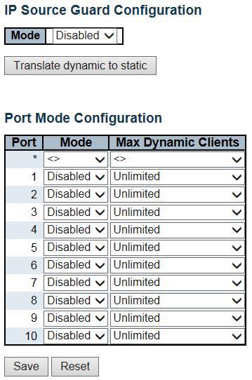
99 99
100 Object Mode of IP Source Guard Configuration Description Enable the Global IP Source Guard or disable the Global IP Source Guard. All configured ACEs will be lost when the mode is enabled. Port Mode Configuration Specify IP Source Guard is enabled on which ports. Only when both Global Mode and Port Mode on a given port are enabled, IP Source Guard is enabled on this given port. Max Dynamic Clients Specify the maximum number of dynamic clients that can be learned on given port. This value can be 0, 1, 2 or unlimited. If the port mode is enabled and the value of max dynamic client is equal to 0, it means only allow the IP packets forwarding that are matched in static entries on the specific port. Buttons Click to save changes. Click to undo any changes made locally and revert to previously saved values. Click to translate all dynamic entries to static entries. 100

101 IP Source Guard Static Table Object Description Delete Port VLAN ID IP Address MAC address Check to delete the entry. It will be deleted during the next save. The logical port for the settings. The vlan id for the settings. Allowed Source IP address. Allowed Source MAC address. Buttons Click to add a new entry to the Static IP Source Guard table. Click to save changes. Click to undo any changes made locally and revert to previously saved values ARP Inspection 101
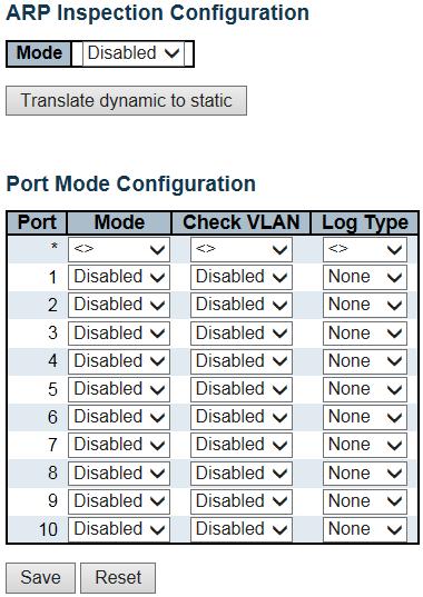
102 102
103 Object Mode of ARP Inspection Description Enable the Global ARP Inspection or disable the Global ARP Inspection. Configuration Port Mode Configuration Specify ARP Inspection is enabled on which ports. Only when both Global Mode and Port Mode on a given port are enabled, ARP Inspection is enabled on this given port. 103
104 Possible modes are: Enabled: Enable ARP Inspection operation. Disabled: Disable ARP Inspection operation. If you want to inspect the VLAN configuration, you have to enable the setting of "Check VLAN". The default setting of "Check VLAN" is disabled. When the setting of "Check VLAN" is disabled, the log type of ARP Inspection will refer to the port setting. And the setting of "Check VLAN" is enabled, the log type of ARP Inspection will refer to the VLAN setting. Possible setting of "Check VLAN" are: Enabled: Enable check VLAN operation. Disabled: Disable check VLAN operation. Only the Global Mode and Port Mode on a given port are enabled, and the setting of "Check VLAN" is disabled, the log type of ARP Inspection will refer to the port setting. There are four log types and possible types are: None: Log nothing. Deny: Log denied entries. Permit: Log permitted entries. ALL: Log all entries. 104
105 Buttons Click to save changes. Click to undo any changes made locally and revert to previously saved values. Click to translate all dynamic entries to static entries VLAN Configuration Each page shows up to 9999 entries from the VLAN table, default being 20, selected through the "entries per page" input field. When first visited, the web page will show the first 20 entries from the beginning of the VLAN Table. The first displayed will be the one with the lowest VLAN ID found in the VLAN Table. The "VLAN" input fields allow the user to select the starting point in the VLAN Table. Clicking the button will update the displayed table starting from that or the closest next VLAN Table match. The will use the next entry of the currently displayed VLAN entry as a basis for the next lookup. When the end is reached the warning message is shown in the displayed table. Use the button to start over. Specify ARP Inspection is enabled on which VLANs. First, you have to enable the port setting on Port mode configuration web page. Only when both Global Mode and Port Mode on a given port are enabled, ARP Inspection is enabled on this given port. Second, you can specify which VLAN will be inspected on VLAN mode configuration web page. The log type also can be configured on per VLAN setting. Possible types are: 105
106 None: Log nothing. Deny: Log denied entries. Permit: Log permitted entries. ALL: Log all entries Buttons Click to save changes. Click to undo any changes made locally and revert to previously saved values. Click to add a new VLAN to the ARP Inspection VLAN table Static Table Object Description Delete Port VLAN ID MAC Address IP Address Check to delete the entry. It will be deleted during the next save. The logical port for the settings The vlan id for the settings. Allowed Source MAC address in ARP request packets. Allowed Source IP address in ARP request packets. 106
107 Buttons Click to add a new entry to the Static ARP Inspection table. Click to save changes. Click to undo any changes made locally and revert to previously saved values Dynamic Table Each page shows up to 99 entries from the Dynamic ARP Inspection table, default being 20, selected through the "entries per page" input field. When first visited, the web page will show the first 20 entries from the beginning of the Dynamic ARP Inspection Table. The "Start from port address", "VLAN", "MAC address" and "IP address" input fields allow the user to select the starting point in the Dynamic ARP Inspection Table. Clicking the button will update the displayed table starting from that or the closest next Dynamic ARP Inspection Table match. In addition, the two input fields will - upon a button click - assume the value of the first displayed entry, allowing for continuous refresh with the same start address. The will use the last entry of the currently displayed table as a basis for the next lookup. When the end is reached the text "No more entries" is shown in the displayed table. Use the button to start over. Object Description Port VLAN ID Switch Port Number for which the entries are displayed. VLAN-ID in which the ARP traffic is permitted. 107
108 MAC Address IP Address Translate to static User MAC address of the entry. User IP address of the entry. Select the checkbox to translate the entry to static entry. Buttons Check this box to refresh the page automatically. Automatic refresh occurs every 3 seconds. Refreshes the displayed table starting from the input fields. Click to save changes. Click to undo any changes made locally and revert to previously saved values. Updates the table starting from the first entry in the Dynamic ARP Inspection Table. Updates the table, starting with the entry after the last entry currently displayed RADIUS This page allows you to configure the RADIUS servers. 108

109 Object Description Global Configuration Timeout Timeout is the number of seconds, in the range 1 to 1000, to wait for a reply from a RADIUS server before retransmitting the request. Retransmit Retransmit is the number of times, in the range 1 to 1000, a RADIUS request is retransmitted to a server that is not responding. If the server has not responded after the last retransmit it is considered to be dead. Deadtime Deadtime, which can be set to a number between 0 to 1440 minutes, is the period during which the switch will not send new requests to a server that has failed to respond to a previous request. This will stop the switch from continually trying to contact a server that it has already determined as dead. Setting the Deadtime to a value greater than 0 (zero) will enable this feature, but only if more than one server has been configured. Key The secret key - up to 63 characters long - shared between the RADIUS server and the switch. 109
110 NAS-IP-Address(Attribute 4) NAS-IPv6-Address(Attribute 95) NAS-Identifier (Attribute 32) The IPv4 address to be used as attribute 4 in RADIUS Access-Request packets. If this field is left blank, the IP address of the outgoing interface is used. The IPv6 address to be used as attribute 95 in RADIUS Access-Request packets. If this field is left blank, the IP address of the outgoing interface is used. The identifier - up to 253 characters long - to be used as attribute 32 in RADIUS Access-Request packets. If this field is left blank, the NAS-Identifier is not included in the packet. Server Configuration Delete To delete a RADIUS server entry, check this box. The entry will be deleted during the next Save. Hostname Auth Port Acct Port Timeout The IP address or hostname of the RADIUS server. The UDP port to use on the RADIUS server for authentication. The UDP port to use on the RADIUS server for accounting. This optional setting overrides the global timeout value. Leaving it blank will use the global timeout value. Retransmit This optional setting overrides the global retransmit value. Leaving it blank will use the global retransmit value. Key This optional setting overrides the global key. Leaving it blank will use the global key. Buttons Click to add a new RADIUS server, up to 5 servers are supported. The button can be used to undo the addition of the new server. Click to save changes. Click to undo any changes made locally and revert to previously saved values TACACS+ This page allows you to configure the TACACS+ servers. 110

111 Object Description Global Configuration Timeout Timeout is the number of seconds, in the range 1 to 1000, to wait for a reply from a TACACS+ server before it is considered to be dead. Deadtime Deadtime, which can be set to a number between 0 to 1440 minutes, is the period during which the switch will not send new requests to a server that has failed to respond to a previous request. This will stop the switch from continually trying to contact a server that it has already determined as dead. Setting the Deadtime to a value greater than 0 (zero) will enable this feature, but only if more than one server has been configured. Key The secret key - up to 63 characters long - shared between the TACACS+ server and the switch. Server Configuration Delete To delete a TACACS+ server entry, check this box. The entry will be deleted during the next Save. Hostname The IP address or hostname of the TACACS+ server. 111
112 Port Timeout The TCP port to use on the TACACS+ server for authentication. This optional setting overrides the global timeout value. Leaving it blank will use the global timeout value. Key This optional setting overrides the global key. Leaving it blank will use the global key. Buttons Click to add a new TACACS+ server, up to 5 servers are supported. The button can be used to undo the addition of the new server. Click to save changes. Click to undo any changes made locally and revert to previously saved values Static Aggregation This page is used to configure the Aggregation hash mode and the aggregation group. 112
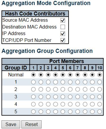
113 113
114 Object Description Hash Code Contributors Source MAC Address The Source MAC address can be used to calculate the destination port for the frame. Check to enable the use of the Source MAC address, or uncheck to disable. By default, Source MAC Address is enabled. Destination MAC Address The Destination MAC Address can be used to calculate the destination port for the frame. Check to enable the use of the Destination MAC Address, or uncheck to disable. By default, Destination MAC Address is disabled. IP Address The IP address can be used to calculate the destination port for the frame. Check to enable the use of the IP Address, or uncheck to disable. By default, IP Address is enabled. TCP/UDP Port Number The TCP/UDP port number can be used to calculate the destination port for the frame. Aggregation Group Configuration Check to enable the use of the TCP/UDP Port Number, or uncheck to disable. By default, TCP/UDP Port Number is enabled. Group ID Indicates the group ID for the settings contained in the same row. Group ID "Normal" indicates there is no aggregation. Only one group ID is valid per port. Port Members Each switch port is listed for each group ID. Select a radio button to include a port in an aggregation, or clear the radio button to remove the port from the aggregation. By default, no ports belong to any aggregation group. Only full duplex ports can join an aggregation and ports must be in the same speed in each group. Buttons Click to save changes. Click to undo any changes made locally and revert to previously saved values LACP Aggregation 114

115 This page allows the user to inspect the current LACP port configurations, and possibly change them as well. 115
116 Object Description Port LACP Enabled The switch port number. Controls whether LACP is enabled on this switch port. LACP will form an aggregation when 2 or more ports are connected to the same partner. Key The Key value incurred by the port, range The Auto setting will set the key as appropriate by the physical link speed, 10Mb = 1, 100Mb = 2, 1Gb = 3. Using the Specific setting, a user-defined value can be entered. Ports with the same Key value can participate in the same aggregation group, while ports with different keys cannot. Role The Role shows the LACP activity status. The Active will transmit LACP packets each second, while Passive will wait for a LACP packet from a partner (speak if spoken to). Timeout The Timeout controls the period between BPDU transmissions. Fast will transmit LACP packets each second, while Slow will wait for 30 seconds before sending a LACP packet. Prio The Prio controls the priority of the port. If the LACP partner wants to form a larger group than is supported by this device then this parameter will control which ports will be active and which ports will be in a backup role. Lower number means greater priority. Buttons Click to save changes. Click to undo any changes made locally and revert to previously saved values Loop Protection This page allows the user to inspect the current Loop Protection configurations, and possibly change them as well. 116
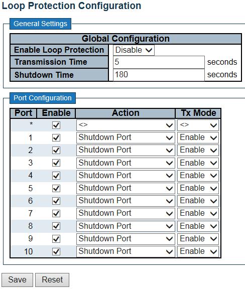
117 117
118 Object Description General Settings Enable Loop Protection Controls whether loop protections is enabled (as a whole). Transmission Time The interval between each loop protection PDU sent on each port, valid values are 1 to 10 seconds. Shutdown Time The period (in seconds) for which a port will be kept disabled in the event of a loop is detected (and the port action shuts down the port). Valid values are 0 to seconds (7 days). A value of zero will keep a port disabled (until next device restart). Port Configuration Port Enable Action The switch port number of the port. Controls whether loop protection is enabled on this switch port. Configures the action performed when a loop is detected on a port. Valid values are Shutdown Port, Shutdown Port and Log or Log Only. Tx Mode Controls whether the port is actively generating loop protection PDU's, or whether it is just passively looking for looped PDU's. Buttons Click to save changes. Click to undo any changes made locally and revert to previously saved values Spanning Tree Bridge Settings This page allows you to configure STP system settings. The settings are used by all STP Bridge instances in the Switch 118
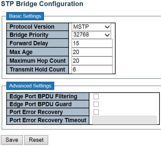
119 119
120 Object Description Basic Settings Protocol Version The MSTP / RSTP / STP protocol version setting. Valid values are STP, RSTP and MSTP. Bridge Priority Controls the bridge priority. Lower numeric values have better priority. The bridge priority plus the MSTI instance number, concatenated with the 6-byte MAC address of the switch forms a Bridge Identifier. For MSTP operation, this is the priority of the CIST. Otherwise, this is the priority of the STP/RSTP bridge Forward Delay The delay used by STP Bridges to transit Root and Designated Ports to Forwarding (used in STP compatible mode). Valid values are in the range 4 to 30 seconds. Max Age The maximum age of the information transmitted by the Bridge when it is the Root Bridge. Valid values are in the range 6 to 40 seconds Maximum Hop Count This defines the initial value of remaining Hops for MSTI information generated at the boundary of an MSTI region. It defines how many bridges a root bridge can distribute its BPDU information to. Valid values are in the range 6 to 40 hops. Transmit Hold Count The number of BPDU's a bridge port can send per second. When exceeded, transmission of the next BPDU will be delayed. Valid values are in the range 1 to 10 BPDU's per second. Advanced Settings Edge Port BPDU Control whether a port explicitly configured as Edge will transmit and receive BPDUs. Filtering Edge Port BPDU Guard Control whether a port explicitly configured as Edge will disable itself upon reception of a BPDU. The port will enter the error-disabled state, and will be removed from the active topology. Port Error Recovery Control whether a port in the error-disabled state automatically will be enabled after a certain time. If recovery is not enabled, ports have to be disabled and re-enabled for normal STP operation. The condition is also cleared by a system reboot. Port Error Recovery Timeout The time to pass before a port in the error-disabled state can be enabled. Valid values are between 30 and seconds (24 hours). 120
121 Buttons Click to save changes. Click to undo any changes made locally and revert to previously saved values MSTI Mapping This page allows the user to inspect the current STP MSTI bridge instance priority configurations, and possibly change them as well. 121
122 122
123 Object Description Configuration Identification Configuration Name The name identifying the VLAN to MSTI mapping. Bridges must share the name and revision (see below), as well as the VLAN-to-MSTI mapping configuration in order to share spanning trees for MSTI's (Intra-region). The name is at most 32 characters. Configuration Revision The revision of the MSTI configuration named above. This must be an integer between 0 and MSTI Mapping MSTI The bridge instance. The CIST is not available for explicit mapping, as it will receive the VLANs not explicitly mapped. VLANs Mapped The list of VLANs mapped to the MSTI. The VLANs can be given as a single (xx, xx being between 1 and 4094) VLAN, or a range (xx-yy), each of which must be separated with comma and/or space. A VLAN can only be mapped to one MSTI. An unused MSTI should just be left empty. (I.e. not having any VLANs mapped to it.) Example: 2,5, Buttons Click to save changes. Click to undo any changes made locally and revert to previously saved values MSTI Priorities This page allows the user to inspect the current STP MSTI bridge instance priority configurations, and possibly change them as well. 123
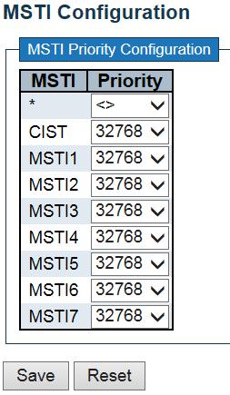
124 124
125 Object Description MSTI Priorities The bridge instance. The CIST is the default instance, which is always active. Controls the bridge priority. Lower numeric values have better priority. The bridge priority plus the MSTI instance number, concatenated with the 6-byte MAC address of the switch forms a Bridge Identifier. Click to save changes. Click to undo any changes made locally and revert to previously saved values CIST Ports well. This page allows the user to inspect the current STP CIST port configurations, and possibly change them as This page contains settings for physical and aggregated ports. 125

126 Object Description Port STP Enabled The switch port number of the logical STP port. Controls whether STP is enabled on this switch port. 126
127 Path Cost Controls the path cost incurred by the port. The Auto setting will set the path cost as appropriate by the physical link speed, using the 802.1D recommended values. Using the Specific setting, a user-defined value can be entered. The path cost is used when establishing the active topology of the network. Lower path cost ports are chosen as forwarding ports in favour of higher path cost ports. Valid values are in the range 1 to Priority Controls the port priority. This can be used to control priority of ports having identical port cost. (See above). operedge (state flag) Operational flag describing whether the port is connecting directly to edge devices. (No Bridges attached). Transition to the forwarding state is faster for edge ports (having operedge true) than for other ports. The value of this flag is based on AdminEdge and AutoEdge fields. This flag is displayed as Edge in Monitor->Spanning Tree -> STP Detailed Bridge Status. AdminEdge Controls whether the operedge flag should start as set or cleared. (The initial operedge state when a port is initialized). AutoEdge Controls whether the bridge should enable automatic edge detection on the bridge port. This allows operedge to be derived from whether BPDU's are received on the port or not. Restricted Role If enabled, causes the port not to be selected as Root Port for the CIST or any MSTI, even if it has the best spanning tree priority vector. Such a port will be selected as an Alternate Port after the Root Port has been selected. If set, it can cause lack of spanning tree connectivity. It can be set by a network administrator to prevent bridges external to a core region of the network influence the spanning tree active topology, possibly because those bridges are not under the full control of the administrator. This feature is also known as Root Guard. Restricted TCN If enabled, causes the port not to propagate received topology change notifications and topology changes to other ports. If set it can cause temporary loss of connectivity after changes in a spanning tree's active topology as a result of persistently incorrect learned station location information. It is set by a network administrator to prevent bridges external to a core region of the network, causing address flushing in that region, possibly because those bridges are not under the full control of the administrator or the physical link state of the attached LANs transits frequently. 127

128 BPDU Guard If enabled, causes the port to disable itself upon receiving valid BPDU's. Contrary to the similar bridge setting, the port Edge status does not effect this setting. A port entering error-disabled state due to this setting is subject to the bridge Port Error Recovery setting as well. Point-to-Point Controls whether the port connects to a point-to-point LAN rather than to a shared medium. This can be automatically determined, or forced either true or false. Transition to the forwarding state is faster for point-to-point LANs than for shared media. Buttons Click to save changes. Click to undo any changes made locally and revert to previously saved values MSTI Ports This page allows the user to inspect the current STP MSTI port configurations, and possibly change them as well. An MSTI port is a virtual port, which is instantiated separately for each active CIST (physical) port for each MSTI instance configured on and applicable to the port. The MSTI instance must be selected before displaying actual MSTI port configuration options. This page contains MSTI port settings for physical and aggregated ports. 128
129 Click to retrieve settings for a specific MSTI, the page displayed as follow. 129
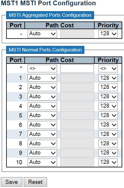
130 130
131 Object Description Port Path Cost The switch port number of the corresponding STP CIST (and MSTI) port. Controls the path cost incurred by the port. The Auto setting will set the path cost as appropriate by the physical link speed, using the 802.1D recommended values. Using the Specific setting, a user-defined value can be entered. The path cost is used when establishing the active topology of the network. Lower path cost ports are chosen as forwarding ports in favour of higher path cost ports. Valid values are in the range 1 to Priority Controls the port priority. This can be used to control priority of ports having identical port cost. (See above). Buttons Click to retrieve settings for a specific MSTI. Click to save changes. Click to undo any changes made locally and revert to previously saved values IPMC Profile Profile Table This page provides IPMC Profile related configurations. The IPMC profile is used to deploy the access control on IP multicast streams. It is allowed to create at maximum 64 Profiles with at maximum 128 corresponding rules for each. 131
132 Object Global Profile Mode Enable/Disable the Global IPMC Profile. Description System starts to do filtering based on profile settings only when the global profile mode is enabled. Delete Check to delete the entry. The designated entry will be deleted during the next save. Profile Name The name used for indexing the profile table. Each entry has the unique name which is composed of at maximum 16 alphabetic and numeric characters. At least one alphabet must be present. Profile Description Additional description, which is composed of at maximum 64 alphabetic and numeric characters, about the profile. No blank or space characters are permitted as part of description. Use "_" or "-" to separate the description sentence. Rule When the profile is created, click the edit button to enter the rule setting page of the designated profile. Summary about the designated profile will be shown by clicking the view button. You can manage or inspect the rules of the designated profile by using the following buttons: : List the rules associated with the designated profile. : Adjust the rules associated with the designated profile. 132
133 Buttons Click to add new IPMC profile. Specify the name and configure the new entry. Click "Save". Click to save changes. Click to undo any changes made locally and revert to previously saved values Address Entry This page provides address range settings used in IPMC profile. The address entry is used to specify the address range that will be associated with IPMC Profile. It is allowed to create at maximum 128 address entries in the system. Object Description Delete Check to delete the entry. The designated entry will be deleted during the next save. Entry Name The name used for indexing the address entry table. Each entry has the unique name which is composed of at maximum 16 alphabetic and numeric characters. At least one alphabet must be present. Start Address The starting IPv4/IPv6 Multicast Group Address that will be used as an address range. End Address The ending IPv4/IPv6 Multicast Group Address that will be used as an address range. 133
134 Buttons Click to add new address range. Specify the name and configure the addresses. Click "Save" Click to save changes. Click to undo any changes made locally and revert to previously saved values. Refreshes the displayed table starting from the input fields. Updates the table starting from the first entry in the IPMC Profile Address Configuration. Updates the table, starting with the entry after the last entry currently displayed MVR This page provides MVR related configurations. The MVR feature enables multicast traffic forwarding on the Multicast VLANs. In a multicast television application, a PC or a network television or a set-top box can receive the multicast stream. Multiple set-top boxes or PCs can be connected to one subscriber port, which is a switch port configured as an MVR receiver port. When a subscriber selects a channel, the set-top box or PC sends an IGMP/MLD report message to Switch A to join the appropriate multicast group address. Uplink ports that send and receive multicast data to and from the multicast VLAN are called MVR source ports. It is allowed to create at maximum 4 MVR VLANs with corresponding channel profile for each Multicast VLAN. The channel profile is defined by the IPMC Profile which provides the filtering conditions. 134
135 Object Description MVR Mode Enable/Disable the Global MVR. The Unregistered Flooding control depends on the current configuration in IGMP/MLD Snooping. It is suggested to enable Unregistered Flooding control when the MVR group table is full. Delete MVR VID Check to delete the entry. The designated entry will be deleted during the next save. Specify the Multicast VLAN ID. Be Caution: MVR source ports are not recommended to be overlapped with management VLAN ports. MVR Name MVR Name is an optional attribute to indicate the name of the specific MVR VLAN. Maximum length of the MVR VLAN Name string is 16. MVR VLAN Name can only contain alphabets or numbers. When the optional MVR VLAN name is given, it should contain at least one alphabet. MVR VLAN name can be edited for the existing MVR VLAN entries or it can be added to the new entries. 135
136 IGMP Address Define the IPv4 address as source address used in IP header for IGMP control frames. The default IGMP address is not set ( ). When the IGMP address is not set, system uses IPv4 management address of the IP interface associated with this VLAN. When the IPv4 management address is not set, system uses the first available IPv4 management address. Otherwise, system uses a pre-defined value. By default, this value will be Mode Specify the MVR mode of operation. In Dynamic mode, MVR allows dynamic MVR membership reports on source ports. In Compatible mode, MVR membership reports are forbidden on source ports. The default is Dynamic mode. Tagging Specify whether the traversed IGMP/MLD control frames will be sent as Untagged or Tagged with MVR VID. The default is Tagged. Priority Specify how the traversed IGMP/MLD control frames will be sent in prioritized manner. The default Priority is 0. LLQI Define the maximum time to wait for IGMP/MLD report memberships on a receiver port before removing the port from multicast group membership. The value is in units of tenths of a seconds. The range is from 0 to The default LLQI is 5 tenths or one-half second. Interface Channel Profile When the MVR VLAN is created, select the IPMC Profile as the channel filtering condition for the specific MVR VLAN. Summary about the Interface Channel Profiling (of the MVR VLAN) will be shown by clicking the view button. Profile selected for designated interface channel is not allowed to have overlapped permit group address. Profile Management You can inspect the rules of the designated profile by using the following button: Button Port : List the rules associated with the designated profile. The logical port for the settings. 136
137 Port Role Configure an MVR port of the designated MVR VLAN as one of the following roles. Inactive: The designated port does not participate MVR operations. Source: Configure uplink ports that receive and send multicast data as source ports. Subscribers cannot be directly connected to source ports. Receiver: Configure a port as a receiver port if it is a subscriber port and should only receive multicast data. It does not receive data unless it becomes a member of the multicast group by issuing IGMP/MLD messages. Be Caution: MVR source ports are not recommended to be overlapped with management VLAN ports. Select the port role by clicking the Role symbol to switch the setting. I indicates Inactive; S indicates Source; R indicates Receiver The default Role is Inactive. Immediate Leave Enable the fast leave on the port. Buttons Click to add new MVR VLAN. Specify the VID and configure the new entry. Click "Save". Click to save changes. Click to undo any changes made locally and revert to previously saved values IPMC IGMP Snooping Basic Configuration This page provides IGMP Snooping related configuration. 137
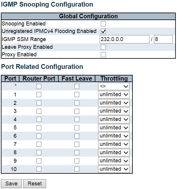
138 138
139 Object Description Snooping Enabled Unregistered IPMCv4 Flooding Enabled Enable the Global IGMP Snooping. Enable unregistered IPMCv4 traffic flooding. The flooding control takes effect only when IGMP Snooping is enabled. When IGMP Snooping is disabled, unregistered IPMCv4 traffic flooding is always active in spite of this setting. IGMP SSM Range SSM (Source-Specific Multicast) Range allows the SSM-aware hosts and routers run the SSM service model for the groups in the address range. Leave Proxy Enabled Enable IGMP Leave Proxy. This feature can be used to avoid forwarding unnecessary leave messages to the router side. Proxy Enabled Enable IGMP Proxy. This feature can be used to avoid forwarding unnecessary join and leave messages to the router side. Router Port Specify which ports act as router ports. A router port is a port on the Ethernet switch that leads towards the Layer 3 multicast device or IGMP querier. If an aggregation member port is selected as a router port, the whole aggregation will act as a router port. Fast Leave Throttling Enable the fast leave on the port. Enable to limit the number of multicast groups to which a switch port can belong. Buttons Click to save changes. Click to undo any changes made locally and revert to previously saved values VLAN Configuration Each page shows up to 99 entries from the VLAN table, default being 20, selected through the "entries per page" input field. When first visited, the web page will show the first 20 entries from the beginning of the VLAN Table. The first displayed will be the one with the lowest VLAN ID found in the VLAN Table. The "VLAN" input fields allow the user to select the starting point in the VLAN Table. 139

140 Object Description Delete VLAN ID IGMP Snooping Enabled Check to delete the entry. The designated entry will be deleted during the next save. The VLAN ID of the entry. Enable the per-vlan IGMP Snooping. Up to 32 VLANs can be selected for IGMP Snooping. Querier Election Enable to join IGMP Querier election in the VLAN. Disable to act as an IGMP Non-Querier. Querier Address Define the IPv4 address as source address used in IP header for IGMP Querier election. When the Querier address is not set, system uses IPv4 management address of the IP interface associated with this VLAN. When the IPv4 management address is not set, system uses the first available IPv4 management address. Otherwise, system uses a pre-defined value. By default, this value will be Compatibility Compatibility is maintained by hosts and routers taking appropriate actions depending on the versions of IGMP operating on hosts and routers within a network. The allowed selection is IGMP-Auto, Forced IGMPv1, Forced IGMPv2, Forced IGMPv3, default compatibility value is IGMP-Auto. PRI Priority of Interface. It indicates the IGMP control frame priority level generated by the system. These values can be used to prioritize different classes of traffic. The allowed range is 0 (best effort) to 7 (highest), default interface priority value is
141 RV Robustness Variable. The Robustness Variable allows tuning for the expected packet loss on a network. The allowed range is 1 to 255, default robustness variable value is 2. QI Query Interval. The Query Interval is the interval between General Queries sent by the Querier. The allowed range is 1 to seconds, default query interval is 125 seconds. QRI Query Response Interval. The Maximum Response Delay used to calculate the Maximum Response Code inserted into the periodic General Queries. The allowed range is 0 to in tenths of seconds, default query response interval is 100 in tenths of seconds (10 seconds). LLQI(LMQI for IGMP) Last Member Query Interval. The Last Member Query Time is the time value represented by the Last Member Query Interval, multiplied by the Last Member Query Count. The allowed range is 0 to in tenths of seconds, default last member query interval is 10 in tenths of seconds (1 second). URI Unsolicited Report Interval. The Unsolicited Report Interval is the time between repetitions of a host's initial report of membership in a group. The allowed range is 0 to seconds, default unsolicited report interval is 1 second. Buttons Refreshes the displayed table starting from the "VLAN" input fields. Updates the table starting from the first entry in the VLAN Table, i.e. the entry with the lowest VLAN ID. Updates the table, starting with the entry after the last entry currently displayed. Click to add new IGMP VLAN. Specify the VID and configure the new entry. Click "Save". The specific IGMP VLAN starts working after the corresponding static VLAN is also created. Click to save changes. 141
142 Click to undo any changes made locally and revert to previously saved values. 142

143 Port Filtering Profile Object Description Port Filtering Profile The logical port for the settings. Select the IPMC Profile as the filtering condition for the specific port. Summary about the designated profile will be shown by clicking the view button. Profile Management Button You can inspect the rules of the designated profile by using the following button: : List the rules associated with the designated profile. Buttons Click to save changes. Click to undo any changes made locally and revert to previously saved values. 143

144 MLD Snooping Basic Configuration This page provides MLD Snooping related configuration. Object Description Snooping Enable Enable the Global MLD Snooping. 144
145 Unregistered IPMCv6 Flooding Enable Enable unregistered IPMCv6 traffic flooding. The flooding control takes effect only when MLD Snooping is enabled. When MLD Snooping is disabled, unregistered IPMCv6 traffic flooding is always active in spite of this setting. MLD SSM Range SSM (Source-Specific Multicast) Range allows the SSM-aware hosts and routers run the SSM service model for the groups in the address range. Leave Proxy Enable Enable MLD Leave Proxy. This feature can be used to avoid forwarding unnecessary leave messages to the router side. Proxy Enable Enable MLD Proxy. This feature can be used to avoid forwarding unnecessary join and leave messages to the router side. Router Port Specify which ports act as router ports. A router port is a port on the Ethernet switch that leads towards the Layer 3 multicast device or MLD querier. If an aggregation member port is selected as a router port, the whole aggregation will act as a router port. Fast Leave Throttling Enable the fast leave on the port. Enable to limit the number of multicast groups to which a switch port can belong. Buttons Click to save changes. Click to undo any changes made locally and revert to previously saved values VLAN Configuration Each page shows up to 99 entries from the VLAN table, default being 20, selected through the "entries per page" input field. When first visited, the web page will show the first 20 entries from the beginning of the VLAN Table. The first displayed will be the one with the lowest VLAN ID found in the VLAN Table. The "VLAN" input fields allow the user to select the starting point in the VLAN Table. 145

146 Object Description Delete VLAN ID MLD Snooping Enabled Check to delete the entry. The designated entry will be deleted during the next save. The VLAN ID of the entry. Enable the per-vlan MLD Snooping. Up to 32 VLANs can be selected for MLD Snooping. Querier Election Enable to join MLD Querier election in the VLAN. Disable to act as a MLD Non-Querier. Compatibility Compatibility is maintained by hosts and routers taking appropriate actions depending on the versions of MLD operating on hosts and routers within a network. The allowed selection is MLD-Auto, Forced MLDv1, Forced MLDv2, default compatibility value is MLD-Auto. PRI Priority of Interface. It indicates the MLD control frame priority level generated by the system. These values can be used to prioritize different classes of traffic. The allowed range is 0 (best effort) to 7 (highest), default interface priority value is 0. RV Robustness Variable. The Robustness Variable allows tuning for the expected packet loss on a link. The allowed range is 1 to 255, default robustness variable value is 2. QI Query Interval. The Query Interval is the interval between General Queries sent by the Querier. The allowed range is 1 to seconds, default query interval is 125 seconds. QRI Query Response Interval. The Maximum Response Delay used to calculate the Maximum Response Code inserted into the periodic General Queries. The allowed range is 0 to in tenths of seconds, default query response interval is 100 in tenths of seconds (10 seconds). 146
147 LLQI Last Listener Query Interval. The Last Listener Query Interval is the Maximum Response Delay used to calculate the Maximum Response Code inserted into Multicast Address Specific Queries sent in response to Version 1 Multicast Listener Done messages. It is also the Maximum Response Delay used to calculate the Maximum Response Code inserted into Multicast Address and Source Specific Query messages. The allowed range is 0 to in tenths of seconds, default last listener query interval is 10 in tenths of seconds (1 second). URI Unsolicited Report Interval. The Unsolicited Report Interval is the time between repetitions of a node's initial report of interest in a multicast address. The allowed range is 0 to seconds, default unsolicited report interval is 1 second. 147
148 Buttons Refreshes the displayed table starting from the "VLAN" input fields. Updates the table starting from the first entry in the VLAN Table, i.e. the entry with the lowest VLAN ID. Updates the table, starting with the entry after the last entry currently displayed. Click to add new MLD VLAN. Specify the VID and configure the new entry. Click "Save". The specific MLD VLAN starts working after the corresponding static VLAN is also created. Click to save changes. Click to undo any changes made locally and revert to previously saved values Port Filtering Profile = Object Description Port Filtering Profile The logical port for the settings. Select the IPMC Profile as the filtering condition for the specific port. Summary about the designated profile will be shown by clicking the view button. Profile Management Button You can inspect the rules of the designated profile by using the following button: : List the rules associated with the designated profile. Buttons Click to save changes. 148

149 Click to undo any changes made locally and revert to previously saved values LLDP This page allows the user to inspect and configure the current LLDP port settings. 149
150 Object Description LLDP Parameters Tx Interval The switch periodically transmits LLDP frames to its neighbors for having the network discovery information up-to-date. The interval between each LLDP frame is determined by the Tx Interval value. Valid values are restricted to seconds. Tx Hold Each LLDP frame contains information about how long the information in the LLDP frame shall be considered valid. The LLDP information valid period is set to Tx Hold multiplied by Tx Interval seconds. Valid values are restricted to 2-10 times. Tx Delay If some configuration is changed (e.g. the IP address) a new LLDP frame is transmitted, but the time between the LLDP frames will always be at least the value of Tx Delay seconds. Tx Delay cannot be larger than 1/4 of the Tx Interval value. Valid values are restricted to seconds. Tx Reinit When a port is disabled, LLDP is disabled or the switch is rebooted, an LLDP shutdown frame is transmitted to the neighboring units, signalling that the LLDP information isn't valid anymore. Tx Reinit controls the amount of seconds between the shutdown frame and a new LLDP initialization. Valid values are restricted to 1 10 seconds. LLDP Port Parameters Port Mode The switch port number of the logical LLDP port. Select LLDP mode. Rx only The switch will not send out LLDP information, but LLDP information from neighbor units is analyzed. Tx only The switch will drop LLDP information received from neighbors, but will send out LLDP information. Disabled The switch will not send out LLDP information, and will drop LLDP information received from neighbors. Enabled The switch will send out LLDP information, and will analyze LLDP information received from neighbors. 150
151 CDP Aware Select CDP awareness. The CDP operation is restricted to decoding incoming CDP frames (The switch doesn't transmit CDP frames). CDP frames are only decoded if LLDP on the port is enabled. Only CDP TLVs that can be mapped to a corresponding field in the LLDP neighbors' table are decoded. All other TLVs are discarded (Unrecognized CDP TLVs and discarded CDP frames are not shown in the LLDP statistics.). CDP TLVs are mapped onto LLDP neighbors' table as shown below. CDP TLV "Device ID" is mapped to the LLDP "Chassis ID" field. CDP TLV "Address" is mapped to the LLDP "Management Address" field. The CDP address TLV can contain multiple addresses, but only the first address is shown in the LLDP neighbors table. CDP TLV "Port ID" is mapped to the LLDP "Port ID" field. CDP TLV "Version and Platform" is mapped to the LLDP "System Description" field. Both the CDP and LLDP support "system capabilities", but the CDP capabilities cover capabilities that are not part of the LLDP. These capabilities are shown as "others" in the LLDP neighbors' table. If all ports have CDP awareness disabled the switch forwards CDP frames received from neighbor devices. If at least one port has CDP awareness enabled all CDP frames are terminated by the switch. NOTE: When CDP awareness on a port is disabled the CDP information isn't removed immediately, but gets removed when the hold time is exceeded. Port Descr Sys Name Sys Descr Sys Capa Mgmt Addr Optional TLV: When checked the "port description" is included in LLDP information transmitted. Optional TLV: When checked the "system name" is included in LLDP information transmitted. Optional TLV: When checked the "system description" is included in LLDP information transmitted. Optional TLV: When checked the "system capability" is included in LLDP information transmitted. Optional TLV: When checked the "management address" is included in LLDP information transmitted. 151

152 LLDP-MED This page allows you to configure the LLDP-MED. This function applies to VoIP devices which support LLDP-MED. Buttons Click to save changes. Click to undo any changes made locally and revert to previously saved values. 152
153 Object Description Fast start repeat count Fast start repeat count Rapid startup and Emergency Call Service Location Identification Discovery of endpoints is a critically important aspect of VoIP systems in general. In addition, it is best to advertise only those pieces of information which are specifically relevant to particular endpoint types (for example only advertise the voice network policy to permitted voice-capable devices), both in order to conserve the limited LLDPU space and to reduce security and system integrity issues that can come with inappropriate knowledge of the network policy. With this in mind LLDP-MED defines an LLDP-MED Fast Start interaction between the protocol and the application layers on top of the protocol, in order to achieve these related properties. Initially, a Network Connectivity Device will only transmit LLDP TLVs in an LLDPDU. Only after an LLDP-MED Endpoint Device is detected, will an LLDP-MED capable Network Connectivity Device start to advertise LLDP-MED TLVs in outgoing LLDPDUs on the associated port. The LLDP-MED application will temporarily speed up the transmission of the LLDPDU to start within a second, when a new LLDP-MED neighbor has been detected in order share LLDP-MED information as fast as possible to new neighbors. Because there is a risk of an LLDP frame being lost during transmission between neighbors, it is recommended to repeat the fast start transmission multiple times to increase the possibility of the neighbors receiving the LLDP frame. With Fast start repeat count it is possible to specify the number of times the fast start transmission would be repeated. The recommended value is 4 times, given that 4 LLDP frames with a 1 second interval will be transmitted, when an LLDP frame with new information is received. It should be noted that LLDP-MED and the LLDP-MED Fast Start mechanism is only intended to run on links between LLDP-MED Network Connectivity Devices and Endpoint Devices, and as such does not apply to links between LAN infrastructure elements, including Network Connectivity Devices, or other types of links. Coordinates Location 153
154 Latitude Latitude SHOULD be normalized to within 0-90 degrees with a maximum of 4 digits. It is possible to specify the direction to either North of the equator or South of the equator. Longitude Longitude SHOULD be normalized to within degrees with a maximum of 4 digits. It is possible to specify the direction to either East of the prime meridian or West of the prime meridian. Altitude Altitude SHOULD be normalized to within to with a maximum of 4 digits. It is possible to select between two altitude types (floors or meters). Meters: Representing meters of Altitude defined by the vertical datum specified. Floors: Representing altitude in a form more relevant in buildings which have different floor-to-floor dimensions. An altitude = 0.0 is meaningful even outside a building, and represents ground level at the given latitude and longitude. Inside a building, 0.0 represents the floor level associated with ground level at the main entrance. Map Datum The Map Datum is used for the coordinates given in these options: WGS84: (Geographical 3D) - World Geodesic System 1984, CRS Code 4327, Prime Meridian Name: Greenwich. NAD83/NAVD88: North American Datum 1983, CRS Code 4269, Prime Meridian Name: Greenwich; The associated vertical datum is the North American Vertical Datum of 1988 (NAVD88). This datum pair is to be used when referencing locations on land, not near tidal water (which would use Datum = NAD83/MLLW). NAD83/MLLW: North American Datum 1983, CRS Code 4269, Prime Meridian Name: Greenwich; The associated vertical datum is Mean Lower Low Water (MLLW). This datum pair is to be used when referencing locations on water/sea/ocean. Civic Address Location 154
155 Country code The two-letter ISO 3166 country code in capital ASCII letters - Example: DK, DE or US. State County City City district Block (Neighborhood) Street National subdivisions (state, canton, region, province, prefecture). County, parish, gun (Japan), district. City, township, shi (Japan) - Example: Copenhagen. City division, borough, city district, ward, chou (Japan). Neighborhood, block. Street - Example: Poppelvej. Leading street direction Leading street direction - Example: N. Trailing street suffix Street suffix Trailing street suffix - Example: SW. Street suffix - Example: Ave, Platz. House no. House number - Example: 21. House no. suffix House number suffix - Example: A, 1/2. Landmark Additional location info Name Landmark or vanity address - Example: Columbia University. Additional location info - Example: South Wing. Name (residence and office occupant) - Example: Flemming Jahn. Zip code Postal/zip code - Example: Building Building (structure) - Example: Low Library. Apartment Unit (Apartment, suite) - Example: Apt 42. Floor Floor - Example: 4. Room no. Room number - Example: 450F. Place type Postal community name Place type - Example: Office. Postal community name - Example: Leonia. P.O. Box Post office box (P.O. BOX) - Example: Additional code Additional code - Example: Emergency Call Service Emergency Call Service Emergency Call Service ELIN identifier data format is defined to carry the ELIN identifier as used during emergency call setup to a traditional CAMA or ISDN trunk-based PSAP. This format consists of a numerical digit string, corresponding to the ELIN to be used for emergency calling. Policies Delete Check to delete the policy. It will be deleted during the next save. 155
156 Policy ID ID for the policy. This is auto generated and shall be used when selecting the policies that shall be mapped to the specific ports. Application Type Intended use of the application types: 1. Voice - for use by dedicated IP Telephony handsets and other similar appliances supporting interactive voice services. These devices are typically deployed on a separate VLAN for ease of deployment and enhanced security by isolation from data applications. 2. Voice Signalling (conditional) - for use in network topologies that require a different policy for the voice signalling than for the voice media. This application type should not be advertised if all the same network policies apply as those advertised in the Voice application policy. 3. Guest Voice - support a separate 'limited feature-set' voice service for guest users and visitors with their own IP Telephony handsets and other similar appliances supporting interactive voice services. 4. Guest Voice Signalling (conditional) - for use in network topologies that require a different policy for the guest voice signalling than for the guest voice media. This application type should not be advertised if all the same network policies apply as those advertised in the Guest Voice application policy. 5. Softphone Voice - for use by softphone applications on typical data centric devices, such as PCs or laptops. This class of endpoints frequently does not support multiple VLANs, if at all, and are typically configured to use an 'untagged' VLAN or a single 'tagged' data specific VLAN. When a network policy is defined for use with an 'untagged' VLAN (see Tagged flag below), then the L2 priority field is ignored and only the DSCP value has relevance. 6. Video Conferencing - for use by dedicated Video Conferencing equipment and other similar appliances supporting real-time interactive video/audio services. 7. Streaming Video - for use by broadcast or multicast based video content distribution and other similar applications supporting streaming video services that 156
157 require specific network policy treatment. Video applications relying on TCP with buffering would not be an intended use of this application type. 8. Video Signalling (conditional) - for use in network topologies that require a separate policy for the video signalling than for the video media. This application type should not be advertised if all the same network policies apply as those advertised in the Video Conferencing application policy. Tag Tag indicating whether the specified application type is using a 'tagged' or an 'untagged' VLAN. Untagged indicates that the device is using an untagged frame format and as such does not include a tag header as defined by IEEE 802.1Q In this case, both the VLAN ID and the Layer 2 priority fields are ignored and only the DSCP value has relevance. Tagged indicates that the device is using the IEEE 802.1Q tagged frame format, and that both the VLAN ID and the Layer 2 priority values are being used, as well as the DSCP value. The tagged format includes an additional field, known as the tag header. The tagged frame format also includes priority tagged frames as defined by IEEE 802.1Q VLAN ID L2 Priority VLAN identifier (VID) for the port as defined in IEEE 802.1Q L2 Priority is the Layer 2 priority to be used for the specified application type. L2 Priority may specify one of eight priority levels (0 through 7), as defined by IEEE 802.1D A value of 0 represents use of the default priority as defined in IEEE 802.1D DSCP DSCP value to be used to provide Diffserv node behaviour for the specified application type as defined in IETF RFC DSCP may contain one of 64 code point values (0 through 63). A value of 0 represents use of the default DSCP value as defined in RFC Adding a new policy Click to add a new policy. Specify the Application type, Tag, VLAN ID, L2 Priority and DSCP for the new policy. Click "Save". The number of policies supported is
158 Port Policies Configuration Port Policy Id The port number to which the configuration applies. The set of policies that shall apply to a given port. The set of policies is selected by check marking the checkboxes that corresponds to the policies. Buttons Click to save changes. Click to undo any changes made locally and revert to previously saved values MAC Table The MAC Address Table is configured on this page. Set timeouts for entries in the dynamic MAC Table and configure the static MAC table here. 158

159 Object Description Aging Configuration Disable Automatic Aging Aging Time Disable the automatic aging of dynamic entries by ticking the item. Enter a value in seconds. The allowed range is 10 to seconds. MAC Table Learning Auto Disable Learning is done automatically as soon as a frame with unknown SMAC is received. No learning is done. 159
160 Secure Only static MAC entries are learned, all other frames are dropped. Note: Make sure that the link used for managing the switch is added to the Static Mac Table before changing to secure learning mode, otherwise the management link is lost and can only be restored by using another non-secure port or by connecting to the switch via the serial interface. Static MAC Table Learning Delete VLAN ID MAC Address Port Members Check to delete the entry. It will be deleted during the next save. The VLAN ID of the entry. The MAC address of the entry. Checkmarks indicate which ports are members of the entry. Check or uncheck as Adding a New Static needed to modify the entry. Entry Click to add a new entry to the static MAC table. Specify the VLAN ID, MAC address, and port members for the new entry. Click "Save". Buttons Click to save changes. Click to undo any changes made locally and revert to previously saved values VLANs This page allows for controlling VLAN configuration on the switch. The page is divided into a global section and a per-port configuration section. 160

161 Object Description Global VLAN Configuration Allowed Access VLANs This field shows the allowed Access VLANs, i.e. it only affects ports configured as Access ports. Ports in other modes are members of all VLANs specified in the Allowed VLANs field. By default, only VLAN 1 is enabled. More VLANs may be created by using a list syntax where the individual elements are separated by commas. Ranges are specified with a dash separating the lower and upper bound. The following example will create VLANs 1, 10, 11, 12, 13, 200, and 300: 1,10-13,200,300. Spaces are allowed in between the delimiters. Ethertype for Custom S-ports This field specifies the ethertype/tpid (specified in hexadecimal) used for Custom S-ports. The setting is in force for all ports whose Port Type is set to S-Custom-Port. Port VLAN Configuration Port Mode This is the logical port number of this row. The port mode (default is Access) determines the fundamental behavior of the port in question. A port can be in one of three modes as described below. Whenever a particular mode is selected, the remaining fields in that row will be either grayed out or made changeable depending on the mode in question. 161
162 Access Access ports are normally used to connect to end stations. Dynamic features like Voice VLAN may add the port to more VLANs behind the scenes. Access ports have the following characteristics: Member of exactly one VLAN, the Port VLAN (a.k.a. Access VLAN), which by default is 1 Accepts untagged and C-tagged frames Discards all frames that are not classified to the Access VLAN On egress all frames classified to the Access VLAN are transmitted untagged. Other (dynamically added VLANs) are transmitted tagged Trunk Trunk ports can carry traffic on multiple VLANs simultaneously, and are normally used By default, a trunk port is member of all VLANs (1-4095) The VLANs that a trunk port is member of may be limited by the use of Allowed VLANs Frames classified to a VLAN that the port is not a member of are discarded By default, all frames but frames classified to the Port VLAN (a.k.a. Native VLAN) get tagged on egress. Frames classified to the Port VLAN do not get C-tagged on egress Egress tagging can be changed to tag all frames, in which case only tagged frames are accepted on ingress 162
163 Hybrid Hybrid ports resemble trunk ports in many ways, but adds additional port configuration features. In addition to the characteristics described for trunk ports, hybrid ports have these abilities: Can be configured to be VLAN tag unaware, C-tag aware, S-tag aware, or S-custom-tag aware Ingress filtering can be controlled Ingress acceptance of frames and configuration of egress tagging can be configured independently Port VLAN Determines the port's VLAN ID (a.k.a. PVID). Allowed VLANs are in the range 1 through 4095, default being 1. On ingress, frames get classified to the Port VLAN if the port is configured as VLAN unaware, the frame is untagged, or VLAN awareness is enabled on the port, but the frame is priority tagged (VLAN ID = 0). On egress, frames classified to the Port VLAN do not get tagged if Egress Tagging configuration is set to untag Port VLAN. The Port VLAN is called an "Access VLAN" for ports in Access mode and Native VLAN for ports in Trunk or Hybrid mode. 163
164 Port Type Ports in hybrid mode allow for changing the port type, that is, whether a frame's VLAN tag is used to classify the frame on ingress to a particular VLAN, and if so, which TPID it reacts on. Likewise, on egress, the Port Type determines the TPID of the tag, if a tag is required. Unaware: On ingress, all frames, whether carrying a VLAN tag or not, get classified to the Port VLAN, and possible tags are not removed on egress. C-Port: On ingress, frames with a VLAN tag with TPID = 0x8100 get classified to the VLAN ID embedded in the tag. If a frame is untagged or priority tagged, the frame gets classified to the Port VLAN. If frames must be tagged on egress, they will be tagged with a C-tag. S-Port: On ingress, frames with a VLAN tag with TPID = 0x8100 or 0x88A8 get classified to the VLAN ID embedded in the tag. If a frame is untagged or priority tagged, the frame gets classified to the Port VLAN. If frames must be tagged on egress, they will be tagged with an S-tag. S-Custom-Port: On ingress, frames with a VLAN tag with a TPID = 0x8100 or equal to the Ethertype configured for Custom-S ports get classified to the VLAN ID embedded in the tag. If a frame is untagged or priority tagged, the frame gets classified to the Port VLAN. If frames must be tagged on egress, they will be tagged with the custom S-tag. Ingress Filtering Hybrid ports allow for changing ingress filtering. Access and Trunk ports always have ingress filtering enabled. If ingress filtering is enabled (checkbox is checked), frames classified to a VLAN that the port is not a member of get discarded. If ingress filtering is disabled, frames classified to a VLAN that the port is not a member of are accepted and forwarded to the switch engine. However, the port will never transmit frames classified to VLANs that it is not a member of. 164
165 Ingress Acceptance Hybrid ports allow for changing the type of frames that are accepted on ingress. Tagged and Untagged Both tagged and untagged frames are accepted. Tagged Only Only tagged frames are accepted on ingress. Untagged frames are discarded. Untagged Only Only untagged frames are accepted on ingress. Tagged frames are discarded. Egress Tagging Ports in Trunk and Hybrid mode may control the tagging of frames on egress. Untag Port VLAN Frames classified to the Port VLAN are transmitted untagged. Other frames are transmitted with the relevant tag. Tag All All frames, whether classified to the Port VLAN or not, are transmitted with a tag. Untag All All frames, whether classified to the Port VLAN or not, are transmitted without a tag. This option is only available for ports in Hybrid mode. Allowed VLANs Ports in Trunk and Hybrid mode may control which VLANs they are allowed to become members of. Access ports can only be member of one VLAN, the Access VLAN. The field's syntax is identical to the syntax used in the Enabled VLANs field. By default, a Trunk or Hybrid port will become member of all VLANs, and is therefore set to The field may be left empty, which means that the port will not become member of any VLANs. Forbidden VLANs A port may be configured to never be member of one or more VLANs. This is particularly useful when dynamic VLAN protocols like MVRP and GVRP must be prevented from dynamically adding ports to VLANs. The trick is to mark such VLANs as forbidden on the port in question. The syntax is identical to the syntax used in the Enabled VLANs field. By default, the field is left blank, which means that the port may become a member of all possible VLANs. 165

166 Buttons Description Click to save changes. Click to undo any changes made locally and revert to previously saved values Private VLANs Membership The Private VLAN membership configurations for the switch can be monitored and modified here. Private VLANs can be added or deleted here. Port members of each Private VLAN can be added or removed here. Private VLANs are based on the source port mask, and there are no connections to VLANs. This means that VLAN IDs and Private VLAN IDs can be identical. A port must be a member of both a VLAN and a Private VLAN to be able to forward packets. By default, all ports are VLAN unaware and members of VLAN 1 and Private VLAN 1. A VLAN unaware port can only be a member of one VLAN, but it can be a member of multiple Private VLANs. Object Description 166
167 Delete To delete a private VLAN entry, check this box. The entry will be deleted during the next save. PVLAN ID Port members Indicates the ID of this particular private VLAN. A row of check boxes for each port is displayed for each private VLAN ID. To include a port in a Private VLAN, check the box. To remove or exclude the port from the Private VLAN, make sure the box is unchecked. By default, no ports are members, and all boxes are unchecked. Adding a New Private VLAN Click to add a new private VLAN ID. An empty row is added to the table, and the private VLAN can be configured as needed. The allowed range for a private VLAN ID is the same as the switch port number range. Any values outside this range are not accepted, and a warning message appears. Click "OK" to discard the incorrect entry, or click "Cancel" to return to the editing and make a correction. The Private VLAN is enabled when you click "Save". The VLANs. button can be used to undo the addition of new Private Buttons Click to refresh the page immediately. Click to add a new private VLAN ID Click to save changes. Click to undo any changes made locally and revert to previously saved values. 167

168 Port Isolation This page is used for enabling or disabling port isolation on ports in a Private VLAN. A port member of a VLAN can be isolated to other isolated ports on the same VLAN and Private VLAN. Object Port Members Description A check box is provided for each port of a private VLAN. When checked, port isolation is enabled on that port. When unchecked, port isolation is disabled on that port. By default, port isolation is disabled on all ports. Buttons Check this box to refresh the page automatically. Automatic refresh occurs every 3 seconds. Click to refresh the page immediately. Click to save changes. Click to undo any changes made locally and revert to previously saved values. 168
169 VCL Industrial Managed Gigabit Ethernet Switch Web Configuration Tool Guide MAC-based VLAN The MAC-based VLAN entries can be configured here. This page allows for adding and deleting MACbased VLAN entries and assigning the entries to different ports. This page shows only static entries. Object Description Delete To delete a MAC-based VLAN entry, check this box and press save. The entry will be deleted in the stack. MAC Address VLAN ID Port Members Indicates the MAC address. Indicates the VLAN ID. A row of check boxes for each port is displayed for each MAC-based VLAN entry. To include a port in a MAC-based VLAN, check the box. To remove or exclude the port from the MAC-based VLAN, make sure the box is unchecked. By default, no ports are members, and all boxes are unchecked. Adding a New MAC-based VLAN Click to add a new MAC-based VLAN entry. An empty row is added to the table, and the MAC-based VLAN entry can be configured as needed. Any unicast MAC address can be configured for the MAC-based VLAN entry. No broadcast or multicast MAC addresses are allowed. Legal values for a VLAN ID are 1 through The MAC-based VLAN entry is enabled when you click on "Save". A MAC-based VLAN without any port members will be deleted when you click "Save". The button can be used to undo the addition of new MAC-based VLANs. The maximum possible MAC-based VLAN entries are limited to
170 Buttons Click to save changes. Click to undo any changes made locally and revert to previously saved values. Check this box to refresh the page automatically. Automatic refresh occurs every 3 seconds. Refreshes the displayed table. Updates the table starting from the first entry in the MAC-based VLAN Table. Updates the table, starting with the entry after the last entry currently displayed. 170

171 Protocol-based VLAN Protocol to Group This page allows you to add new protocols to Group Name (unique for each Group) mapping entries as well as allow you to see and delete already mapped entries for the switch. Object Description Delete To delete a Protocol to Group Name map entry, check this box. The entry will be deleted on the switch during the next Save. Frame Type Frame Type can have one of the following values: Ethernet LLC SNAP NOTE: On changing the Frame type field, valid value of the following text field will vary depending on the new frame type you selected. Value Valid value that can be entered in this text field depends on the option selected from the preceding Frame Type selection menu. Below is the criteria for three different Frame Types: For Ethernet: Values in the text field when Ethernet is selected as a Frame Type is called etype. Valid values for etype ranges from 0x0600-0xffff For LLC: Valid value in this case is comprised of two different sub-values. a. DSAP: 1-byte long string (0x00-0xff) 171
172 b. SSAP: 1-byte long string (0x00-0xff) For SNAP: Valid value in this case also is comprised of two different sub-values. a. OUI: OUI (Organizationally Unique Identifier) is value in format of xx-xx-xx where each pair (xx) in string is a hexadecimal value ranges from 0x00-0xff. b. PID: If the OUI is hexadecimal , the protocol ID is the Ethernet type (EtherType) field value for the protocol running on top of SNAP; if the OUI is an OUI for a particular organization, the protocol ID is a value assigned by that organization to the protocol running on top of SNAP. In other words, if value of OUI field is then value of PID will be etype (0x0600-0xffff) and if value of OUI is other than then valid value of PID will be any value from 0x0000 to 0xffff. Group Name A valid Group Name is a unique 16-character long string for every entry which consists of a combination of alphabets (a-z or A-Z) and integers(0-9). Note: special character and underscore(_) are not allowed. Buttons Click to save changes. Click to undo any changes made locally and revert to previously saved values. The button can be used to undo the addition of new entry. The maximum possible Protocol to Group mappings are limited to 128. Click to add a new entry in mapping table. Check this box to refresh the page automatically. Automatic refresh occurs every 3 seconds. Click to refresh the page immediately. 172

173 Group to VLAN This page allows you to map an already-configured Group Name to a VLAN for the switch. Object Description Delete To delete a Group Name to VLAN map entry, check this box. The entry will be deleted on the switch during the next Save. Group Name A valid Group Name is a string at the most 16 characters which consists of a combination of alphabets (a-z or A-Z) and integers(0-9), no special character is allowed. whichever Group name you try map to a VLAN must be present in Protocol to Group mapping table and must not be pre-used by any other existing mapping entry on this page. VLAN ID Indicates the ID to which Group Name will be mapped. A valid VLAN ID ranges from Port Members A row of check boxes for each port is displayed for each Group Name to VLAN ID mapping. To include a port in a mapping, check the box. To remove or exclude the port from the mapping, make sure the box is unchecked. By default, no ports are members, and all boxes are unchecked. Adding a New Group to VLAN mapping entry Click to add a new entry in mapping table. An empty row is added to the table, the Group Name, VLAN ID and port members can be configured as needed. Legal values for a VLAN ID are 1 through The button can be used to undo the addition of new entry. The maximum possible Group to VLAN mappings are limited to

174 Buttons Click to save changes. Click to undo any changes made locally and revert to previously saved values. Click to add a new entry in mapping table. Legal values for a VLAN ID are 1 through The button can be used to undo the addition of new entry. The maximum possible Group to VLAN mappings are limited to 64. Check this box to refresh the page automatically. Automatic refresh occurs every 3 seconds. Click to refresh the page immediately IP Subnet-based VLAN The IP subnet-based VLAN entries can be configured here. This page allows for adding, updating and deleting IP subnet-based VLAN entries and assigning the entries to different ports. This page shows only static entries. Object Description Delete To delete a IP subnet-based VLAN entry, check this box and press save. The entry will be deleted in the stack. VCE ID Indicates the index of the entry. It is user configurable. It's value ranges from If a VCE ID is 0, application will auto-generate the VCE ID for that entry. Deletion and lookup of IP subnet-based VLAN are based on VCE ID. 174
175 IP Address Mask Length VLAN ID Port Members Indicates the IP address. Indicates the network mask length. Indicates the VLAN ID. VLAN ID can be changed for the existing entries. A row of check boxes for each port is displayed for each IP subnet-based VLAN entry. To include a port in a IP subnet-based VLAN, check the box. To remove or exclude the port from the IP subnet-based VLAN, make sure the box is unchecked. By default, no ports are members, and all boxes are unchecked. Buttons Click to save changes. Click to undo any changes made locally and revert to previously saved values. Click to add a new IP subnet-based VLAN entry. Legal values for a VLAN ID are 1 through The button can be used to undo the addition of new IP subnet-based VLANs. The maximum possible IP subnet-based VLAN entries are limited to 128. Check this box to refresh the page automatically. Automatic refresh occurs every 3 seconds. Refreshes the displayed table Voice VLAN Voice VLAN Configuration The Voice VLAN feature enables voice traffic forwarding on the Voice VLAN, then the switch can classify and schedule network traffic. It is recommended that there be two VLANs on a port - one for voice, one for data. Before connecting the IP device to the switch, the IP phone should configure the voice VLAN ID correctly. It should be configured through its own GUI. 175
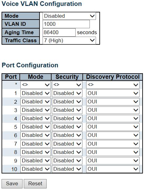
176 176
177 Object Description Mode Indicates the Voice VLAN mode operation. We must disable MSTP feature before we enable Voice VLAN. It can avoid the conflict of ingress filtering. Possible modes are: Enabled: Enable Voice VLAN mode operation. Disabled: Disable Voice VLAN mode operation. VLAN ID Indicates the Voice VLAN ID. It should be a unique VLAN ID in the system and cannot equal each port PVID. It is a conflict in configuration if the value equals management VID, MVR VID, PVID etc. The allowed range is 1 to Aging Time Indicates the Voice VLAN secure learning aging time. The allowed range is 10 to seconds. It is used when security mode or auto detect mode is enabled. In other cases, it will be based on hardware aging time. The actual aging time will be situated between the [age_time; 2 * age_time] interval. Traffic Class Indicates the Voice VLAN traffic class. All traffic on the Voice VLAN will apply this class. Port Mode Indicates the Voice VLAN port mode. Possible port modes are: Disabled: Disjoin from Voice VLAN. Auto: Enable auto detect mode. It detects whether there is VoIP phone attached to the specific port and configures the Voice VLAN members automatically. Forced: Force join to Voice VLAN. Port Security Indicates the Voice VLAN port security mode. When the function is enabled, all non-telephonic MAC addresses in the Voice VLAN will be blocked for 10 seconds. Possible port modes are: Enabled: Enable Voice VLAN security mode operation. Disabled: Disable Voice VLAN security mode operation. Port Discovery Protocol Indicates the Voice VLAN port discovery protocol. It will only work when auto detect mode is enabled. We should enable LLDP feature before configuring discovery protocol to "LLDP" or "Both". Changing the discovery protocol to "OUI" or "LLDP" will restart auto detect process. Possible discovery protocols are: OUI: Detect telephony device by OUI address. LLDP: Detect telephony device by LLDP. Both: Both OUI and LLDP. 177

178 Buttons Click to save changes. Click to undo any changes made locally and revert to previously saved values Voice VLAN OUI Configure VOICE VLAN OUI table on this page. The maximum number of entries is 16. Modifying the OUI table will restart auto detection of OUI process. Object Description Delete Telephony OUI Check to delete the entry. It will be deleted during the next save. A telephony OUI address is a globally unique identifier assigned to a vendor by IEEE. It must be 6 characters long and the input format is "xx-xx-xx" (x is a hexadecimal digit). Description The description of OUI address. Normally, it describes which vendor telephony device it belongs to. The allowed string length is 0 to

179 Buttons Click to add a new access management entry. Click to save changes. Click to undo any changes made locally and revert to previously saved values QoS Port Classification This page allows you to configure the basic QoS Ingress Classification settings for all switch ports. Object Description Port The port number for which the configuration below applies. 179
180 CoS Controls the default class of service. All frames are classified to a CoS. There is a one to one mapping between CoS, queue and priority. A CoS of 0 (zero) has the lowest priority. If the port is VLAN aware, the frame is tagged and Tag Class. is enabled, then the frame is classified to a CoS that is mapped from the PCP and DEI value in the tag. Otherwise the frame is classified to the default CoS. The classified CoS can be overruled by a QCL entry. Note: If the default CoS has been dynamically changed, then the actual default CoS is shown in parentheses after the configured default CoS. DPL Controls the default drop precedence level. All frames are classified to a drop precedence level. If the port is VLAN aware and the frame is tagged, then the frame is classified to a DPL that is equal to the DEI value in the tag. Otherwise the frame is classified to the default DPL. If the port is VLAN aware, the frame is tagged and Tag Class. is enabled, then the frame is classified to a DPL that is mapped from the PCP and DEI value in the tag. Otherwise the frame is classified to the default DPL. The classified DPL can be overruled by a QCL entry. PCP Controls the default PCP value. All frames are classified to a PCP value. If the port is VLAN aware and the frame is tagged, then the frame is classified to the PCP value in the tag. Otherwise the frame is classified to the default PCP value. DEI Controls the default DEI value. All frames are classified to a DEI value. If the port is VLAN aware and the frame is tagged, then the frame is classified to the DEI value in the tag. Otherwise the frame is classified to the default DEI value. 180
181 Tag Class. Shows the classification mode for tagged frames on this port. Disabled: Use default CoS and DPL for tagged frames. Enabled: Use mapped versions of PCP and DEI for tagged frames. Click on the mode in order to configure the mode and/or mapping. NOTE: This setting has no effect if the port is VLAN unaware. Tagged frames received on VLAN unaware ports are always classified to the default CoS and DPL. DSCP Based Address Mode Click to Enable DSCP Based QoS Ingress Port Classification. The IP/MAC address mode specifying whether the QCL classification must be based on source (SMAC/SIP) or destination (DMAC/DIP) addresses on this port. The allowed values are: Source: Enable SMAC/SIP matching. Destination: Enable DMAC/DIP matching. Buttons Click to save changes. Click to undo any changes made locally and revert to previously saved values. 181

182 Port Policing This page allows you to configure the Policer settings for all switch ports. Object Description Port Enabled Rate The port number for which the configuration below applies. Controls whether the policer is enabled on this switch port. Controls the rate for the policer. The default value is 500. This value is restricted to when the "Unit" is "kbps" or "fps", and it is restricted to when the "Unit" is "Mbps" or "kfps". Unit Controls the unit of measure for the policer rate as kbps, Mbps, fps or kfps. The default value is "kbps". Flow Control If flow control is enabled and the port is in flow control mode, then pause frames are sent instead of discarding frames. 182

183 Buttons Click to save changes. Click to undo any changes made locally and revert to previously saved values Port Scheduler This page provides an overview of QoS Egress Port Schedulers for all switch ports. Object Description Port The logical port for the settings contained in the same row. Click on the port number in order to configure the schedulers. Mode Qn Shows the scheduling mode for this port. Shows the weight for this queue and port. 183

184 Port Shaping This page provides an overview of QoS Egress Port Shapers for all switch ports. Object Description Port The logical port for the settings contained in the same row. Click on the port number in order to configure the shapers. Qn Port # Shows "disabled" or actual queue shaper rate - e.g. "800 Mbps". Shows "disabled" or actual port shaper rate - e.g. "800 Mbps" Port Tag Remarking This page provides an overview of QoS Egress Port Tag Remarking for all switch ports. 184

185 Object Description Port The logical port for the settings contained in the same row. Click on the port number in order to configure tag remarking. Mode Shows the tag remarking mode for this port. Classified: Use classified PCP/DEI values. Default: Use default PCP/DEI values. Mapped: Use mapped versions of QoS class and DP level Port DSCP This page allows you to configure the basic QoS Port DSCP Configuration settings for all switch ports. 185
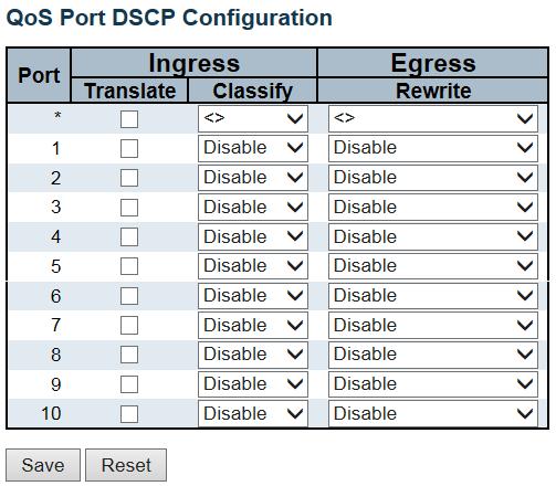
186 186
187 Object Description Port The Port column shows the list of ports for which you can configure dscp ingress and egress settings. Ingress In Ingress settings you can change ingress translation and classification settings for individual ports. There are two configuration parameters available in Ingress: Translate Classify Translate Classify To Enable the Ingress Translation click the checkbox. Classification for a port have 4 different values. -Disable: No Ingress DSCP Classification. -DSCP=0: Classify if incoming (or translated if enabled) DSCP is 0. -Selected: Classify only selected DSCP for which classification is enabled as specified in DSCP Translation window for the specific DSCP. -All: Classify all DSCP. 187
188 Egress Port Egress Rewriting can be one of - -Disable: No Egress rewrite. -Enable: Rewrite enabled without remapping. -Remap DP Unaware: DSCP from analyzer is remapped and frame is remarked with remapped DSCP value. The remapped DSCP value is always taken from the 'DSCP Translation->Egress Remap DP0' table. -Remap DP Aware: DSCP from analyzer is remapped and frame is remarked with remapped DSCP value. Depending on the DP level of the frame, the remapped DSCP value is either taken from the 'DSCP Translation->Egress Remap DP0' table or from the 'DSCP Translation->Egress Remap DP1' table. 188
189 Buttons Click to save changes. Click to undo any changes made locally and revert to previously saved values. 189
190 DSCP-Based QoS This page allows you to configure the basic QoS DSCP based QoS Ingress Classification settings for all switches. 190
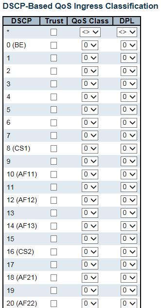
191 191
192 Object Description DSCP Maximum number of supported DSCP values are 64. Trust Controls whether a specific DSCP value is trusted. Only frames with trusted DSCP values are mapped to a specific QoS class and Drop Precedence Level. Frames with untrusted DSCP values are treated as a non-ip frame. Qos Class QoS class value can be any of (0-7) DPL Drop Precedence Level (0-1) Buttons Click to save changes. Click to undo any changes made locally and revert to previously saved values. 192
193 DSCP Translation This page allows you to configure the basic QoS DSCP Translation settings for all switches. DSCP translation can be done in Ingress or Egress. 193
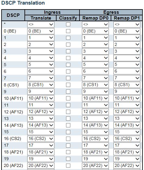
194 194
195 Object Description DSCP Maximum number of supported DSCP values are 64 and valid DSCP value ranges from 0 to 63. Ingress Ingress side DSCP can be first translated to new DSCP before using the DSCP for QoS class and DPL map. There are two configuration parameters for DSCP Translation - Translate Classify Translation Classify DSCP at Ingress side can be translated to any of (0-63) DSCP values. Click to enable Classification at Ingress side. Egress There are the following configurable parameters for Egress side - Remap DP0 Controls the remapping for frames with DP level 0. Remap DP1 Controls the remapping for frames with DP level 1. Remap DP0 Select the DSCP value from select menu to which you want to remap. DSCP value ranges form 0 to 63. Remap DP1 Select the DSCP value from select menu to which you want to remap. DSCP value ranges form 0 to 63. Buttons Click to save changes. Click to undo any changes made locally and revert to previously saved values. 195
.")
196 DSCP Classification This page allows you to configure the mapping of QoS class and Drop Precedence Level to DSCP value. Object Description QoS Class DPL Actual QoS class. Actual Drop Precedence Level. DSCP Select the classified DSCP value (0-63). Button Description Click to save changes. 196
197 Click to undo any changes made locally and revert to previously saved values QoS Control List This page shows the QoS Control List (QCL), which is made up of the QCEs. Each row describes a QCE that is defined. The maximum number of QCEs is 256 on each switch. Click on the lowest plus sign to add a new QCE to the list. Object Description QCE Port DMAC Indicates the QCE id. Indicates the list of ports configured with the QCE. Indicates the destination MAC address. Possible values are: Any: Match any DMAC. Unicast: Match unicast DMAC. Multicast: Match multicast DMAC. Broadcast: Match broadcast DMAC. The default value is 'Any'. SMAC Match specific source MAC address or 'Any'. If a port is configured to match on DMAC/DIP, this field indicates the DMAC. Tag Type Indicates tag type. Possible values are: Any: Match tagged and untagged frames. Untagged: Match untagged frames. Tagged: Match tagged frames. The default value is 'Any'. 197
198 VID Indicates (VLAN ID), either a specific VID or range of VIDs. VID can be in the range or 'Any' PCP Priority Code Point: Valid values of PCP are specific(0, 1, 2, 3, 4, 5, 6, 7) or range(0-1, 2-3, 4-5, 6-7, 0-3, 4-7) or 'Any'. DEI Frame Type Drop Eligible Indicator: Valid value of DEI are 0, 1 or 'Any'. Indicates the type of frame. Possible values are: Any: Match any frame type. Ethernet: Match EtherType frames. LLC: Match (LLC) frames. SNAP: Match (SNAP) frames. IPv4: Match IPv4 frames. IPv6: Match IPv6 frames. Action Indicates the classification action taken on ingress frame if parameters configured are matched with the frame's content. Possible actions are: CoS: Classify Class of Service. DPL: Classify Drop Precedence Level. DSCP: Classify DSCP value. Modification Buttons You can modify each QCE (QoS Control Entry) in the table using the following buttons: : Inserts a new QCE before the current row. : Edits the QCE. : Moves the QCE up the list. : Moves the QCE down the list. : Deletes the QCE. : The lowest plus sign adds a new entry at the bottom of the QCE listings. 198
199 The QCE page includes the following fields: Object Port Members Description Check the checkbox button to include the port in the QCL entry. By default all ports are included. 199
200 Key parameters Key configuration is described as below: DMAC Destination MAC address: Possible values are 'Unicast', 'Multicast', 'Broadcast' or 'Any'. SMAC Source MAC address: xx-xx-xx-xx-xx-xx or 'Any'. If a port is configured to match on DMAC/DIP, this field is the Destination MAC address. Tag Value of Tag field can be 'Untagged', 'Tagged' or 'Any'. VID Valid value of VLAN ID can be any value in the range or 'Any'; user can enter either a specific value or a range of VIDs. PCP Valid value PCP are specific (0, 1, 2, 3, 4, 5, 6, 7) or range (0-1, 2-3, 4-5, 6-7, 0-3, 4-7) or 'Any'. DEI Valid value of DEI can be '0', '1' or 'Any'. Frame Type Frame Type can have any of the following values: Any: Allow all types of frames. EtherType: Ether Type Valid Ether Type can be 0x600-0xFFFF excluding 0x800(IPv4) and 0x86DD(IPv6) or 'Any'. LLC: SSAP Address Valid SSAP(Source Service Access Point) can vary from 0x00 to 0xFF or 'Any'. 200
201 DSAP Address Valid DSAP(Destination Service Access Point) can vary from 0x00 to 0xFF or 'Any'. Control Valid Control field can vary from 0x00 to 0xFF or 'Any'. SNAP: PID Valid PID(a.k.a Ether Type) can be 0x0000-0xFFFF or 'Any'. IPv4: Protocol IP protocol number: (0-255, 'TCP' or 'UDP') or 'Any'. Source IP Specific Source IP address in value/mask format or 'Any'. IP and Mask are in the format x.y.z.w where x, y, z, and w are decimal numbers between 0 and 255. When Mask is converted to a 32-bit binary string and read from left to right, all bits following the first zero must also be zero. If a port is configured to match on DMAC/DIP, this field is the Destination IP address. IP Fragment IPv4 frame fragmented option: 'Yes', 'No' or 'Any'. DSCP Diffserv Code Point value (DSCP): It can be a specific value, range of values or 'Any'. DSCP values are in the range 0-63 including BE, CS1-CS7, EF or AF11-AF43. Sport Source TCP/UDP port:( ) or 'Any', specific or port range applicable for IP protocol UDP/TCP. Dport Destination TCP/UDP port:( ) or 'Any', specific or port range applicable for IP protocol UDP/TCP. IPv6: Protocol IP protocol number: (0-255, 'TCP' or 'UDP') or 'Any'. Source IP 32 LS bits of IPv6 source address in value/mask format or 'Any'. If a port is configured to match on DMAC/DIP, this field is the Destination IP address. DSCP Diffserv Code Point value (DSCP): It can be a specific value, range of values or 'Any'. DSCP values are in the range 0-63 including BE, CS1-CS7, EF or AF11-AF43. Sport Source TCP/UDP port:( ) or 'Any', specific or port range applicable for IP protocol UDP/TCP. Dport Destination TCP/UDP port:( ) or 'Any', specific or port range applicable for IP protocol UDP/TCP. Action Parameters CoS Class of Service: (0-7) or 'Default'. DP Drop Precedence Level: (0-1) or 'Default'. DSCP DSCP: (0-63, BE, CS1-CS7, EF or AF11-AF43) or 'Default'. 'Default' means that the default classified value is not modified by this QCE. Buttons Click to save the configuration and move to main QCL page. 201

202 Click to undo any changes made locally and revert to previously saved values. Return to the previous page without saving the configuration change Storm Control Storm control for the switch is configured on this page. There is a unicast storm rate control, multicast storm rate control, and a broadcast storm rate control. These only affect flooded frames, i.e. frames with a (VLAN ID, DMAC) pair not present on the MAC Address table. The configuration indicates the permitted packet rate for unicast, multicast or broadcast traffic across the switch. Object Frame Type Description The settings in a particular row apply to the frame type listed here: Unicast, Multicast or Broadcast. Enable Rate Enable or disable the storm control status for the given frame type. The rate unit is packets per second (pps). Valid values are: 1, 2, 4, 8, 16, 32, 64, 128, 256, 512, 1K, 2K, 4K, 8K, 16K, 32K, 64K, 128K, 256K, 512K or 1024K. Buttons 202
203 Click to save changes. Click to undo any changes made locally and revert to previously saved values. 203

204 Mirror Configure port Mirroring on this page. To debug network problems, selected traffic can be copied, or mirrored, on a mirror port where a frame analyzer can be attached to analyze the frame flow. The traffic to be copied on the mirror port is selected as follows: All frames received on a given port (also known as ingress or source mirroring) All frames transmitted on a given port (also known as egress or destination mirroring). 204
205 Object Port to mirror Description Port to mirror also known as the mirror port. Frames from ports that have either source (rx) or destination (tx) mirroring enabled are mirrored on this port. Disabled disables mirroring. Port Mode The logical port for the settings contained in the same row. Select mirror mode. Rx only Frames received on this port are mirrored on the mirror port. Frames transmitted are not mirrored. Tx only Frames transmitted on this port are mirrored on the mirror port. Frames received are not mirrored. Disabled Neither frames transmitted nor frames received are mirrored. Enabled Frames received and frames transmitted are mirrored on the mirror port. Note: For a given port, a frame is only transmitted once. It is therefore not possible to mirror mirror port Tx frames. Because of this, mode for the selected mirror port is limited to Disabled or Rx only. Buttons Click to save changes. Click to undo any changes made locally and revert to previously saved values GVR Global Config This page allows you to configure the basic GVRP Configuration settings for all switch ports. 205
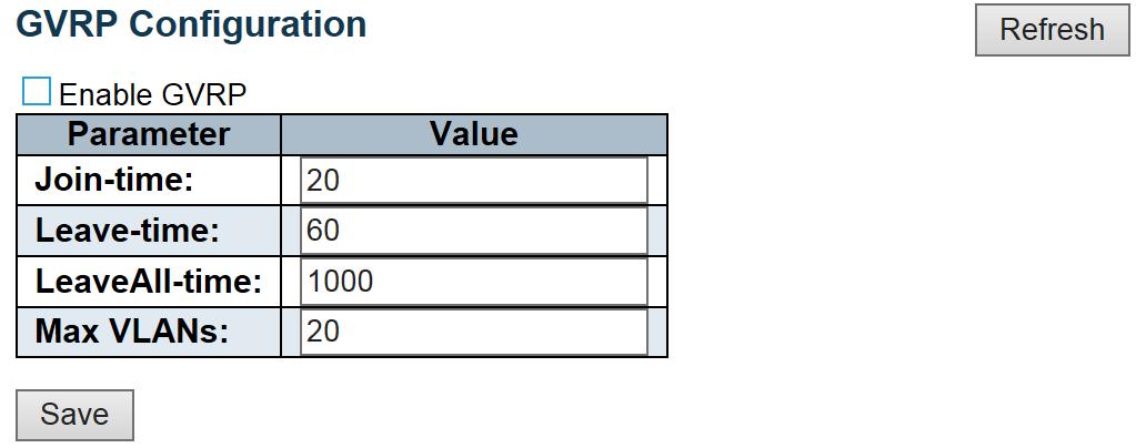
206 206
207 Object GVRP Protocol timers Max number of VLANs Description Join-time is a value in the range 1-20 in the units of centi seconds, i.e. in units of one hundredth of a second. The default is 20. Leave-time is a value in the range in the units of centi seconds, i.e. in units of one hundredth of a second.the default is 60. LeaveAll-time is a value in the range in the units of centi seconds, i.e. in units of one hundredth of a second. The default is When GVRP is enabled a maximum number of VLANs supported by GVRP is specified. By default this number is 20. This number can only be changed when GVRP is turned off. Click to save changes. 207

208 Port Config This page allows you to enable a port for GVRP. Click to save changes. 208

209 sflow This page allows for configuring sflow. The configuration is divided into two parts: Configuration of the sflow receiver (a.k.a. sflow collector) and configuration of per-port flow and counter samplers. sflow configuration is not persisted to non-volatile memory, which means that a reboot will disable sflow sampling. Object Description Agent Configuration IP Address The IP address used as Agent IP address in sflow datagrams. It serves as a unique key that will identify this agent over extended periods of time. Both IPv4 and IPv6 addresses are supported. Receiver Configuration 209
210 Owner Basically, sflow can be configured in two ways: Through local management using the Web or CLI interface or through SNMP. This read-only field shows the owner of the current sflow configuration and assumes values as follows: If sflow is currently unconfigured/unclaimed, Owner contains <none>. If sflow is currently configured through Web or CLI, Owner contains <Configured through local management>. If sflow is currently configured through SNMP, Owner contains a string identifying the sflow receiver. If sflow is configured through SNMP, all controls - except for the Release-button - are disabled to avoid inadvertent reconfiguration. The button allows for releasing the current owner and disable sflow sampling. The button is disabled if sflow is currently unclaimed. If configured through SNMP, the release must be confirmed (a confirmation request will appear). IP Address/Hostname The IP address or hostname of the sflow receiver. Both IPv4 and IPv6 addresses are supported. UDP Port The UDP port on which the sflow receiver listens to sflow datagrams. If set to 0 (zero), the default port (6343) is used. Timeout The number of seconds remaining before sampling stops and the current sflow owner is released. While active, the current time left can be updated with a click on the Refresh-button. If locally managed, the timeout can be changed on the fly without affecting any other settings. Max. Datagram Size The maximum number of data bytes that can be sent in a single sample datagram. This should be set to a value that avoids fragmentation of the sflow datagrams. Valid range is 200 to 1468 bytes with default being 1400 bytes. Port Configuration Port Flow Sampler Enabled The port number for which the configuration below applies. Enables/disables flow sampling on this port. 210
211 Flow Sampler Sampling Rate The statistical sampling rate for packet sampling. Set to N to sample on average 1/Nth of the packets transmitted/received on the port. Not all sampling rates are achievable. If an unsupported sampling rate is requested, the switch will automatically adjust it to the closest achievable. This will be reported back in this field. Flow Sampler Max. Header The maximum number of bytes that should be copied from a sampled packet to the sflow datagram. Valid range is 14 to 200 bytes with default being 128 bytes. If the maximum datagram size does not take into account the maximum header size, samples may be dropped. Counter Poller Enabled Counter Poller Interval Enables/disables counter polling on this port. With counter polling enabled, this specifies the interval - in seconds - between counter poller samples. Buttons See description under Owner. Click to refresh the page. Note that unsaved changes will be lost. Click to save changes. Note that sflow configuration is not persisted to non-volatile memory. Click to undo any changes made locally and revert to previously saved values Ring This page provides Ring related configuration. 211

212 Ring Group Group Index Object Description Select the Ring Group index which you would like to configure it. The group index. This parameter is used for easy to identify the ring when user to configure it. Ring ID The Ring parameter is used for identify whether ring in same group on protocol level. Range: 1 ~ 255 Ring Enabled Master Enable Ring on the specify group. Enable the Ring group on this switch as Master, else the switch will be Slave of the Ring group. Inter-Connection Enable the Ring group as inter-connection group for coupling and multi-homing application. For detail, see application notes. 212
213 Guard timer Guard timer is a timeout value for count down a port from blocking to forwarding state when link up. This is in order to protect the ring do not switch the protection state from Active to Idle frequently when link status is not stable. Range: 10 ~ 3600 seconds. Default value is 10 seconds. Protect Port Select Node1 or Node2 as Ring protection port when the switch is the Master of the Ring. This parameter only can modify in Master of Ring. Node1 Select port of Node1. And also you need to select the port type SF or Non-SF when inter-connection is enabled. SF port(in general case, all of the ring ports must configure as SF port) or Non-SF port(only use for coupling or multi-homing application). For detail, see application notes. Node2 Select port of Node2. And also you need to select the port type SF or Non-SF when inter-connection is enabled. SF port(in general case, all of the ring ports must configure as SF port) or Non-SF port(only use for coupling or multi-homing application). For detail, see application notes. Discovery Enabled Enable the ring neighbor discovery protocol. This parameter only for management purpose. It is in order to let management system to well identify the ring topology. Discovery timer Discovery timer is the timeout value for count down to send ring neighbor discovery protocol to other ring nodes for ring topology discovery purpose. Range: 10 ~ 300 seconds. Default value is 10 seconds. Buttons Click to save changes. Click to undo any changes made locally and revert to previously saved values DDMI 213


214 Configure DDMI on this page. Object Description Mode Enabled Disabled Enable DDMI mode operation. Disable DDMI mode operation. Buttons Click to save changes. Click to undo any changes made locally and revert to previously saved values. 2.4 Monitor System System Information The switch system information is provided here. 214
215 Object Description Contact The system contact configured in Configuration System Information System Contact. Name Location The system name configured in Configuration System Information System Name. The system location configured in Configuration System Information System Location. MAC Address Chip ID System Date The MAC Address of this switch. The Chip ID of this switch. The current (GMT) system time and date. The system time is obtained through the Timing server running on the switch, if any. System Uptime Software Version Software Date The period of time the device has been operational. The software version of this switch. The date when the switch software was produced. Buttons Check this box to refresh the page automatically. Automatic refresh occurs every 3 seconds. Click to refresh the page CPU Load This page displays the CPU load, using line chart. The load is measured as averaged over the last 100ms, 1sec and 10 seconds intervals. The last 1~256 samples (maximum 256) are graphed, and the last numbers are displayed as text as well. 215
216 Buttons Check this box to refresh the page automatically. Automatic refresh occurs every 3 seconds IP Status This page displays the status of the IP protocol layer. The status is defined by the IP interfaces, the IP routes and the neighbour cache (ARP cache) status. 216
. The status flags of the interface (and/or address). IP Routes Network Gateway Status The destination IP network or host address of this route.")
217 Object Description IP Interfaces Interface Type Address Status The name of the interface. The address type of the entry. This may be LINK or IPv4. The current address of the interface (of the given type). The status flags of the interface (and/or address). IP Routes Network Gateway Status The destination IP network or host address of this route. The gateway address of this route. The status flags of the route. Neighbor cache IP Address Link Address The IP address of the entry. The Link (MAC) address for which a binding to the IP address given exist.. Click to refresh the page. Check this box to refresh the page automatically. Automatic refresh occurs every 3 seconds. 217

218 2.4.5 System Log Each page shows up to 999 table entries, selected through the "entries per page" input field. When first visited, the web page will show the beginning entries of this table. The "Level" input field is used to filter the display system log entries. The "Clear Level" input field is used to specify which system log entries will be cleared. To clear specific system log entries, select the clear level first then click button. The "Start from ID" input field allow the user to change the starting point in this table. Clicking the button will update the displayed table starting from that or the closest next entry match. In addition, these input fields will upon entry, allowing for continuous refresh with the same start input field. button click - assume the value of the first displayed The will use the last entry of the currently displayed table as a basis for the next lookup. When the end is reached the text "No more entries" is shown in the displayed table. Use button to start over. Object Description ID Level The identification of the system log entry. The level of the system log entry. Info: The system log entry is belonged information level. Warning: The system log entry is belonged warning level. Error: The system log entry is belonged error level. 218
219 Time Message The occurred time of the system log entry. The detail message of the system log entry. Buttons Check this box to refresh the page automatically. Automatic refresh occurs every 3 seconds. Updates the table entries, starting from the current entry. Flushes the selected entries. Updates the table entries, starting from the first available entry. Updates the table entries, ending at the last entry currently displayed. Updates the table entries, starting from the last entry currently displayed. Updates the table entries, ending at the last available entry. 219
220 2.4.6 System Detailed Log The switch system detailed log information is provided here. Object Description ID Message The ID (>= 1) of the system log entry. The detailed message of the system log entry. Buttons Updates the system log entry to the current entry ID. Updates the system log entry to the first available entry ID. Updates the system log entry to the previous available entry ID. Updates the system log entry to the next available entry ID. Updates the system log entry to the last available entry ID System Alarm Current Alarm is provided on this page. 220

221 Object Description Description Time Alarm Type Description.. Alarm occurrence date time. Buttons Check this box to refresh the page automatically. Automatic refresh occurs every 3 seconds. Click to refresh data Green Ethernet Port Power Saving This page provides the current status for EEE. Object Description Port Link This is the logical port number for this row. Shows if the link is up for the port (green = link up, red = link down). 221
222 EEE Shows if EEE is enabled for the port (reflects the settings at the Port Power Savings configuration page). LP EEE cap EEE Savings Shows if the link partner is EEE capable. Shows if the system is currently saving power due to EEE. When EEE is enabled, the system will powered down if no frame has been received or transmitted in 5 usec. Actiphy Saving PerfectReach Savings Shows if the system is currently saving power due to ActiPhy. Shows if the system is currently saving power due to PerfectReach. 222

223 Buttons Check this box to refresh the page automatically. Automatic refresh occurs every 3 seconds. Click to refresh the page Ports Ports State This page provides an overview of the current switch port states. The port states are illustrated as follows: RJ45 ports SFP ports State Disabled Down Link Buttons Check this box to refresh the page automatically. Automatic refresh occurs every 3 seconds. Click to refresh the page. 223

224 Command Descriptions Traffic Overview This page provides an overview of general traffic statistics for all switch ports. Object Description Port Packet Bytes Errors The logical port for the settings contained in the same row. The number of received and transmitted packets per port. The number of received and transmitted bytes per port. The number of frames received in error and the number of incomplete transmissions per port. Drops Filtered The number of frames discarded due to ingress or egress congestion. The number of received frames filtered by the forwarding process. Buttons Click to refresh the page immediately. Clears the counters for all ports. Check this box to refresh the page automatically. Automatic refresh occurs every 3 seconds. 224

225 Command Descriptions QoS Statistics This page provides statistics for the different queues for all switch ports. Object Description Port Qn Rx/Tx The logical port for the settings contained in the same row. There are 8 QoS queues per port. Q0 is the lowest priority queue. The number of received and transmitted packets per queue Buttons Check this box to refresh the page automatically. Automatic refresh occurs every 3 seconds. Click to refresh the page immediately. Clears the counters for all ports QCL Status This page shows the QCL status by different QCL users. Each row describes the QCE that is defined. It is a conflict if a specific QCE is not applied to the hardware due to hardware limitations. The maximum number of QCEs is 256 on each switch. Object Description User QCE Indicates the QCL user. Indicates the QCE id. 225
226 Command Descriptions Port Frame Type Indicates the list of ports configured with the QCE. Indicates the type of frame. Possible values are: Any: Match any frame type. Ethernet: Match EtherType frames. LLC: Match (LLC) frames. SNAP: Match (SNAP) frames. IPv4: Match IPv4 frames. IPv6: Match IPv6 frames Action Indicates the classification action taken on ingress frame if parameters configured are matched with the frame's content. Possible actions are: CoS: Classify Class of Service. DPL: Classify Drop Precedence Level. DSCP: Classify DSCP value. Conflict Displays Conflict status of QCL entries. As H/W resources are shared by multiple applications. It may happen that resources required to add a QCE may not be available, in that case it shows conflict status as 'Yes', otherwise it is always 'No'. Please note that conflict can be resolved by releasing the H/W resources required to add QCL entry on pressing 'Resolve Conflict' button. Buttons Select the QCL status from this drop down list. Check this box to refresh the page automatically. Automatic refresh occurs every 3 seconds. Click to release the resources required to add QCL entry, in case the conflict status for any QCL entry is 'yes'. Click to refresh the page Detailed Statistics This page provides detailed traffic statistics for a specific switch port. Use the port select box to select which switch port details to display. The displayed counters are the totals for receive and transmit, the size counters for receive and transmit, and the 226
 packets.")
227 Command Descriptions error counters for receive and transmit. Object Description Receive Total and Transmit Total Rx and Tx Packets Rx and Tx Octets The number of received and transmitted (good and bad) packets. The number of received and transmitted (good and bad) bytes. Includes FCS, but excludes framing bits. Rx and Tx Unicast Rx and Tx Multicast Rx and Tx Broadcast Rx and Tx Pause The number of received and transmitted (good and bad) unicast packets. TThe number of received and transmitted (good and bad) multicast packets. The number of received and transmitted (good and bad) broadcast packets. A count of the MAC Control frames received or transmitted on this port that have an opcode indicating a PAUSE operation. Receive and Transmit Size Counters The number of received and transmitted (good and bad) packets split into categories based on their respective frame sizes. Receive and Transmit Queue Counters The number of received and transmitted packets per input and output queue. Receive Error Counters Rx Drops Rx CRC/Alignment Rx Undersize The number of frames dropped due to lack of receive buffers or egress congestion. The number of frames received with CRC or alignment errors. The number of short 1 frames received with valid CRC. 227
228 Command Descriptions Rx Oversize Rx Fragments Rx Jabber Rx Filtered The number of long 2 frames received with valid CRC. The number of short 1 frames received with invalid CRC. The number of long 2 frames received with invalid CRC. The number of received frames filtered by the forwarding process. 1 Short frames are frames that are smaller than 64 bytes. 2 Long frames are frames that are longer than the configured maximum frame length for this port. Transmit Error Counters Tx Drops Tx Late/Exc. Coll The number of frames dropped due to output buffer congestion. The number of frames dropped due to excessive or late collisions. Buttons Click to refresh the page immediately. Click to refresh the page immediately. Check this box to refresh the page automatically. Automatic refresh occurs every 3 seconds DHCP DHCP Server Statistics This page displays the database counters and the number of DHCP messages sent and received by DHCP server. 228
229 Command Descriptions Object Description Database Counters Pool Excluded IP Address Declined IP Address Number of pools. Number of excluded IP address ranges. Number of declined IP addresses. Binding Counters Automatic Binding Manual Binding Number of bindings with network-type pools. Number of bindings that administrator assigns an IP address to a client. That is, the pool is of host type. Expired Binding Number of bindings that their lease time expired or they are cleared from DHCP Message Received Counters Automatic/Manual type bindings. DISCOVER Number of DHCP DISCOVER messages received. 229
230 REQUEST DECLINE RELEASE INFORM Number of DHCP REQUEST messages received. Number of DHCP DECLINE messages received. Number of DHCP RELEASE messages received. Number of DHCP INFORM messages received. DHCP Message Sent Counters OFFER ACK NAK Number of DHCP OFFER messages sent. Number of DHCP ACK messages sent. Number of DHCP NAK messages sent. Buttons Check this box to refresh the page automatically. Automatic refresh occurs every 3 seconds. Click to refresh the page immediately. Click to Clears DHCP Message Received Counters and DHCP Message Sent Counters Binding This page displays bindings generated for DHCP clients. Object Description IP Type State IP address allocated to DHCP client. Type of binding. Possible types are Automatic, Manual, Expired. State of binding. Possible states are Committed, Allocated, Expired. 230
231 Pool Name Server ID The pool that generates the binding. Server IP address to service the binding. Buttons Check this box to refresh the page automatically. Automatic refresh occurs every 3 seconds. Click to refresh the page immediately. Click to clear selected bindings. If the selected binding is Automatic or Manual, then it is changed to be Expired. If the selected binding is Expired, then it is freed. Click to clear all Automatic bindings and Change them to Expired bindings. Click to clear all Manual bindings and Change them to Expired bindings. Click to clear all Expired bindings and free them Declined IP This page displays declined IP addresses. Object Description Declined IP List of IP addresses declined. Buttons 231
232 Check this box to refresh the page automatically. Automatic refresh occurs every 3 seconds. Click to refresh the page immediately DHCP Snooping Table Each page shows up to 99 entries from the Dynamic DHCP snooping table, default being 20, selected through the "entries per page" input field. When first visited, the web page will show the first 20 entries from the beginning of the Dynamic DHCP snooping Table. The "MAC address" and "VLAN" input fields allows the user to select the starting point in the Dynamic DHCP snooping Table. Clicking the button will update the displayed table starting from that or the closest next Dynamic DHCP snooping Table match. In addition, the two input fields will - upon a button click - assume the value of the first displayed entry, allowing for continuous refresh with the same start address. The will use the last entry of the currently displayed table as a basis for the next lookup. When the end is reached the text "No more entries" is shown in the displayed table. Use the button to start over. Object Description MAC Address VLAN ID Source Port IP Address IP Subnet Mask DHCP Server Address User MAC address of the entry. VLAN-ID in which the DHCP traffic is permitted. Switch Port Number for which the entries are displayed. User IP address of the entry. User IP subnet mask of the entry. DHCP Server address of the entry. 232
233 Buttons Check this box to refresh the page automatically. Automatic refresh occurs every 3 seconds. Refreshes the displayed table starting from the input fields. Flushes all dynamic entries. Updates the table starting from the first entry in the Dynamic DHCP snooping Table. Updates the table, starting with the entry after the last entry currently displayed. 233

234 DHCP Relay Statistics This page provides statistics for DHCP relay. Object Description Server Statistics Transmit to Server Transmit Error Receive from Server Receive Missing Agent The number of packets that are relayed from client to server. The number of packets that resulted in errors while being sent to clients. The number of packets received from server. The number of packets received without agent information options. Option Receive Missing Circuit The number of packets received with the Circuit ID option missing. ID Receive Missing Remote The number of packets received with the Remote ID option missing. ID Receive Bad Circuit ID Receive Bad Remote ID The number of packets whose Circuit ID option did not match known circuit ID. The number of packets whose Remote ID option did not match known Remote ID. Client Statistics Transmit to Client Transmit Error Receive from Client Receive Agent Option Replace Agent Option Keep Agent Option The number of relayed packets from server to client. The number of packets that resulted in error while being sent to servers. The number of received packets from server. The number of received packets with relay agent information option. The number of packets which were replaced with relay agent information option. The number of packets whose relay agent information was retained. 234

235 Drop Agent Option The number of packets that were dropped which were received with relay agent information. Check this box to refresh the page automatically. Automatic refresh occurs every 3 seconds. Buttons Click to refresh the page immediately. Clear all statistics DHCP Detailed Statistics This page provides statistics for DHCP snooping. Notice that the normal forward per-port TX statistics isn't increased if the incoming DHCP packet is done by L3 forwarding mechanism. And clear the statistics on specific port may not take effect on global statistics since it gathers the different layer overview. Object Rx and Tx Discover Rx and Tx Offer Rx and Tx Request Rx and Tx Delcine Rx and Tx ACK Rx and Tx NAK Description The number of discover (option 53 with value 1) packets received and transmitted. The number of offer (option 53 with value 2) packets received and transmitted. The number of request (option 53 with value 3) packets received and transmitted. The number of decline (option 53 with value 4) packets received and transmitted. The number of ACK (option 53 with value 5) packets received and transmitted. The number of NAK (option 53 with value 6) packets received and transmitted. 235
236 Rx and Tx Release Rx and Tx Inform Rx and Tx Lease Query The number of release (option 53 with value 7) packets received and transmitted. The number of inform (option 53 with value 8) packets received and transmitted. The number of lease query (option 53 with value 10) packets received and transmitted. Rx and Tx Lease Unassigned Rx and Tx Unknown The number of lease unassigned (option 53 with value 11) packets received and transmitted. The number of lease unknown (option 53 with value 12) packets received and transmitted. Rx and Tx Active The number of lease active (option 53 with value 13) packets received and transmitted. Rx Discarded checksum The number of discard packet that IP/UDP checksum is error. error Rx Discarded from The number of discarded packet that are coming from untrusted port. Untrusted Buttons Check this box to refresh the page automatically. Automatic refresh occurs every 3 seconds. Refreshes the displayed table starting from the input fields. Flushes all dynamic entries Security Access Management Statistics This page provides statistics for access management. 236

237 Object Description Interface Received Packets The interface type through which the remote host can access the switch. Number of received packets from the interface when access management mode is enabled. Allowed Packets Number of allowed packets from the interface when access management mode is enabled. Discarded Packets Number of discarded packets from the interface when access management mode is enabled. 237
238 Buttons Check this box to refresh the page automatically. Automatic refresh occurs every 3 seconds. Click to refresh the page immediately. Clear all statistics Network Port Security Switch This page shows the Port Security status. Port Security is a module with no direct configuration. Configuration comes indirectly from other modules - the user modules. When a user module has enabled port security on a port, the port is set-up for software-based learning. In this mode, frames from unknown MAC addresses are passed on to the port security module, which in turn asks all user modules whether to allow this new MAC address to forward or block it. For a MAC address to be set in the forwarding state, all enabled user modules must unanimously agree on allowing the MAC address to forward. If only one chooses to block it, it will be blocked until that user module decides otherwise. The status page is divided into two sections - one with a legend of user modules and one with the actual port status. 238

239 Object Description User Module Legend User Module Name Abbr The full name of a module that may request Port Security services. A one-letter abbreviation of the user module. This is used in the Users column in the port status table. Port Status Port The port number for which the status applies. Click the port number to see the status for this particular port. Users Each of the user modules has a column that shows whether that module has enabled Port Security or not. A '-' means that the corresponding user module is not enabled, whereas a letter indicates that the user module abbreviated by that letter (see Abbr) has enabled port security. 239
240 State Shows the current state of the port. It can take one of four values: Disabled: No user modules are currently using the Port Security service. Ready: The Port Security service is in use by at least one user module, and is awaiting frames from unknown MAC addresses to arrive. Limit Reached: The Port Security service is enabled by at least the Limit Control user module, and that module has indicated that the limit is reached and no more MAC addresses should be taken in. Shutdown: The Port Security service is enabled by at least the Limit Control user module, and that module has indicated that the limit is exceeded. No MAC addresses can be learned on the port until it is administratively re-opened on the Limit Control configuration Web-page. MAC Count (Current, Limit) The two columns indicate the number of currently learned MAC addresses (forwarding as well as blocked) and the maximum number of MAC addresses that can be learned on the port, respectively. If no user modules are enabled on the port, the Current column will show a dash (-). If the Limit Control user module is not enabled on the port, the Limit column will show a dash (-). Buttons Check this box to refresh the page automatically. Automatic refresh occurs every 3 seconds Click to refresh the page immediately. 240
241 Port This page shows the MAC addresses secured by the Port Security module. Port Security is a module with no direct configuration. Configuration comes indirectly from other modules - the user modules. When a user module has enabled port security on a port, the port is set-up for software-based learning. In this mode, frames from unknown MAC addresses are passed on to the port security module, which in turn asks all user modules whether to allow this new MAC address to forward or block it. For a MAC address to be set in the forwarding state, all enabled user modules must unanimously agree on allowing the MAC address to forward. If only one chooses to block it, it will be blocked until that user module decides otherwise. Object MAC Address & VLAN ID Description The MAC address and VLAN ID that is seen on this port. If no MAC addresses are learned, a single row stating "No MAC addresses attached" is displayed. State Indicates whether the corresponding MAC address is blocked or forwarding. In the blocked state, it will not be allowed to transmit or receive traffic. Time of Addition Age/Hold Shows the date and time when this MAC address was first seen on the port. If at least one user module has decided to block this MAC address, it will stay in the blocked state until the hold time (measured in seconds) expires. If all user modules have decided to allow this MAC address to forward, and aging is enabled, the Port Security module will periodically check that this MAC address still forwards traffic. If the age period (measured in seconds) expires and no frames have been seen, the MAC address will be removed from the MAC table. Otherwise a new age period will begin. If aging is disabled or a user module has decided to hold the MAC address indefinitely, a dash (-) will be shown. Buttons 241

242 Check this box to refresh the page automatically. Automatic refresh occurs every 3 seconds. Click to refresh the page immediately NAS Switch This page provides an overview of the current NAS port states. Object Description Port Admin State The switch port number. Click to navigate to detailed NAS statistics for this port. The port's current administrative state. Refer to NAS Admin State for a description of possible values. Port State The current state of the port. Refer to NAS Port State for a description of the individual states. Last Source The source MAC address carried in the most recently received EAPOL frame for EAPOL-based authentication, and the most recently received frame from a new client for MAC-based authentication. 242
243 Last ID The user name (supplicant identity) carried in the most recently received Response Identity EAPOL frame for EAPOL-based authentication, and the source MAC address from the most recently received frame from a new client for MAC-based authentication. QoS Class Port VLAN ID QoS Class assigned to the port by the RADIUS server if enabled. The VLAN ID that NAS has put the port in. The field is blank, if the Port VLAN ID is not overridden by NAS. If the VLAN ID is assigned by the RADIUS server, "(RADIUS-assigned)" is appended to the VLAN ID. Read more about RADIUS-assigned VLANs here. If the port is moved to the Guest VLAN, "(Guest)" is appended to the VLAN ID. Read more about Guest VLANs here. 243
 statistics, only. Use the port select box to select which port details to be displayed.")
244 Port This page provides detailed NAS statistics for a specific switch port running EAPOL-based IEEE 802.1X authentication. For MAC-based ports, it shows selected backend server (RADIUS Authentication Server) statistics, only. Use the port select box to select which port details to be displayed. Object Description Port State Admin State The port's current administrative state. Refer to NAS Admin State for a description of possible values. Port State The current state of the port. Refer to NAS Port State for a description of the individual states. QoS Class The QoS class assigned by the RADIUS server. The field is blank if no QoS class is assigned. Port VLAN ID The VLAN ID that NAS has put the port in. The field is blank, if the Port VLAN ID is not overridden by NAS. If the VLAN ID is assigned by the RADIUS server, "(RADIUS-assigned)" is appended to the VLAN ID. Read more about RADIUS-assigned VLANs here. If the port is moved to the Guest VLAN, "(Guest)" is appended to the VLAN ID. Read more about Guest VLANs here. Port Counters 244
245 EAPOL Counters These supplicant frame counters are available for the following administrative states: Force Authorized Force Unauthorized Port-based 802.1X Single 802.1X Multi 802.1X 245
246 Backend Server Counters These backend (RADIUS) frame counters are available for the following administrative states: Port-based 802.1X Single 802.1X Multi 802.1X MAC-based Auth. Last Supplicant/Client Info Information about the last supplicant/client that attempted to authenticate. This information is available for the following administrative states: Port-based 802.1X Single 802.1X Multi 802.1X MAC-based Auth. Selected Counters Selected Counters The Selected Counters table is visible when the port is in one of the following administrative states: Multi 802.1X MAC-based Auth. The table is identical to and is placed next to the Port Counters table, and will be empty if no MAC address is currently selected. To populate the table, select one of the attached MAC Addresses from the table below. Attached MAC Addresses Identity Shows the identity of the supplicant, as received in the Response Identity EAPOL frame. Clicking the link causes the supplicant's EAPOL and Backend Server counters to be shown in the Selected Counters table. If no supplicants are attached, it shows No supplicants attached. This column is not available for MAC-based Auth. MAC Address For Multi 802.1X, this column holds the MAC address of the attached supplicant. For MAC-based Auth., this column holds the MAC address of the attached client. Clicking the link causes the client's Backend Server counters to be shown in the Selected Counters table. If no clients are attached, it shows No clients attached. VLAN ID This column holds the VLAN ID that the corresponding client is currently secured through the Port Security module. 246
247 State The client can either be authenticated or unauthenticated. In the authenticated state, it is allowed to forward frames on the port, and in the unauthenticated state, it is blocked. As long as the backend server hasn't successfully authenticated the client, it 247
248 is unauthenticated. If an authentication fails for one or the other reason, the client will remain in the unauthenticated state for Hold Time seconds. Last Authentication Shows the date and time of the last authentication of the client (successful as well as unsuccessful). Buttons Check this box to refresh the page automatically. Automatic refresh occurs every 3 seconds. Click to refresh the page immediat This button is available in the following modes: Force Authorized Force Unauthorized Port-based 802.1X Single 802.1X Click to clear the counters for the selected port. This button is available in the following modes: Multi 802.1X MAC-based Auth.X Click to clear both the port counters and all of the attached client's counters. The "Last Client" will not be cleared, however. This button is available in the following modes: Multi 802.1X MAC-based Auth.X Click to clear only the currently selected client's counters. 248
249 ACL Status This page shows the ACL status by different ACL users. Each row describes the ACE that is defined. It is a conflict if a specific ACE is not applied to the hardware due to hardware limitations. The maximum number of ACEs is 256 on each switch. Object Description User Ingress Port Indicates the ACL user. Indicates the ingress port of the ACE. Possible values are: All: The ACE will match all ingress port. Port: The ACE will match a specific ingress port. Frame Type Indicates the frame type of the ACE. Possible values are: Any: The ACE will match any frame type. EType: The ACE will match Ethernet Type frames. Note that an Ethernet Type based ACE will not get matched by IP and ARP frames. ARP: The ACE will match ARP/RARP frames. IPv4: The ACE will match all IPv4 frames. IPv4/ICMP: The ACE will match IPv4 frames with ICMP protocol. IPv4/UDP: The ACE will match IPv4 frames with UDP protocol. IPv4/TCP: The ACE will match IPv4 frames with TCP protocol. IPv4/Other: The ACE will match IPv4 frames, which are not ICMP/UDP/TCP. IPv6: The ACE will match all IPv6 standard frames. Action Indicates the forwarding action of the ACE. Permit: Frames matching the ACE may be forwarded and learned. Deny: Frames matching the ACE are dropped. Filter: Frames matching the ACE are filtered. Rate limiter Indicates the rate limiter number of the ACE. The allowed range is 1 to 16. When Disabled is displayed, the rate limiter operation is disabled. 249
250 Port Redirect Indicates the port redirect operation of the ACE. Frames matching the ACE are redirected to the port number. The allowed values are Disabled or a specific port number. When Disabled is displayed, the port redirect operation is disabled. 250
251 Mirror Specify the mirror operation of this port. The allowed values are: Enabled: Frames received on the port are mirrored. Disabled: Frames received on the port are not mirrored. The default value is "Disabled". CPU CPU Once Counter Conflict Forward packet that matched the specific ACE to CPU. Forward first packet that matched the specific ACE to CPU. The counter indicates the number of times the ACE was hit by a frame. Indicates the hardware status of the specific ACE. The specific ACE is not applied to the hardware due to hardware limitations. Buttons Check this box to refresh the page automatically. Automatic refresh occurs every 3 seconds.. Click to refresh the page. 251
252 ARP Inspection Each page shows up to 99 entries from the Dynamic ARP Inspection table, default being 20, selected through the "entries per page" input field. When first visited, the web page will show the first 20 entries from the beginning of the Dynamic ARP Inspection Table. The "Start from port address", "VLAN", "MAC address" and "IP address" input fields allow the user to select the starting point in the Dynamic ARP Inspection Table. Clicking the button will update the displayed table starting from that or the closest next Dynamic ARP Inspection Table match. In addition, the two input fields will - upon button click - assume the value of the first displayed entry, allowing for continuous refresh with the same start address. The will use the last entry of the currently displayed table as a basis for the next lookup. When the end is reached the text "No more entries" is shown in the displayed table. Use over. button to start Object Description Port VLAN ID MAC Address IP Address Switch Port Number for which the entries are displayed. VLAN-ID in which the ARP traffic is permitted. User MAC address of the entry. User IP address of the entry. Buttons Check this box to refresh the page automatically. Automatic refresh occurs every 3 seconds. Refreshes the displayed table starting from the input fields. Flushes all dynamic entries. 252
253 Updates the table starting from the first entry in the Dynamic ARP Inspection Table. Updates the table, starting with the entry after the last entry currently displayed IP Source Guard Each page shows up to 99 entries from the Dynamic IP Source Guard table, default being 20, selected through the "entries per page" input field. When first visited, the web page will show the first 20 entries from the beginning of the Dynamic IP Source Guard Table. The "Start from port address", "VLAN" and "IP address" input fields allow the user to select the starting point in the Dynamic IP Source Guard Table. Clicking the button will update the displayed table starting from that or the closest next Dynamic IP Source Guard Table match. In addition, the two input fields will - upon for continuous refresh with the same start address. button click - assume the value of the first displayed entry, allowing The will use the last entry of the currently displayed table as a basis for the next lookup. When the end is reached the text "No more entries" is shown in the displayed table. Use start over. button to Object Description Port VLAN ID IP Address MAC Address Switch Port Number for which the entries are displayed. VLAN-ID in which the IP traffic is permitted. User IP address of the entry. Source MAC address. Buttons 253

254 Check this box to refresh the page automatically. Automatic refresh occurs every 3 seconds. Refresh the displayed table starting from the input fields. Flush all dynamic entries. Update the table starting from the first entry in the Dynamic IP Source Guard Table. Updates the table, starting with the entry after the last entry currently displayed AAA RADIUS Overview This page provides an overview of the status of the RADIUS servers configurable on the Authentication configuration page. Object Description RADIUS Authentication Servers # The RADIUS server number. Click to navigate to detailed statistics for this server. IP Address The IP address and UDP port number (in <IP Address>:<UDP Port> notation) of this server. 254
255 Status The current status of the server. This field takes one of the following values: Disabled: The server is disabled. Not Ready: The server is enabled, but IP communication is not yet up and running. Ready: The server is enabled, IP communication is up and running, and the RADIUS module is ready to accept access attempts. Dead (X seconds left): Access attempts were made to this server, but it did not reply within the configured timeout. The server has temporarily been disabled, but will get re-enabled when the dead-time expires. The number of seconds left before this occurs is displayed in parentheses. This state is only reachable when more than one server is enabled. RADIUS Accounting Servers # The RADIUS server number. Click to navigate to detailed statistics for this server. IP Address The IP address and UDP port number (in <IP Address>:<UDP Port> notation) of this server. Status The current status of the server. This field takes one of the following values: Disabled: The server is disabled. Not Ready: The server is enabled, but IP communication is not yet up and running. Ready: The server is enabled, IP communication is up and running, and the RADIUS module is ready to accept accounting attempts. Dead (X seconds left): Accounting attempts were made to this server, but it did not reply within the configured timeout. The server has temporarily been disabled, but will get re-enabled when the dead-time expires. The number of seconds left before this occurs is displayed in parentheses. This state is only reachable when more than one server is enabled. Buttons Check this box to refresh the page automatically. Automatic refresh occurs every 3 seconds. Click to refresh the page immediately RADIUS Details This page provides detailed statistics for a particular RADIUS server. 255
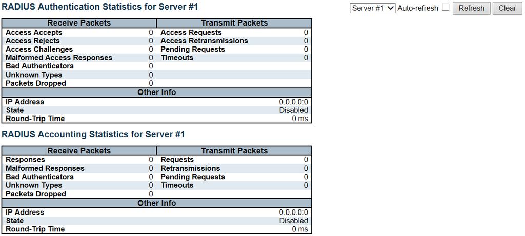
256 256
257 Object Description RADIUS Authentication Statistics Packet Counters RADIUS authentication server packet counter. There are seven receive and four transmit counters. Other Info This section contains information about the state of the server and the latest RADIUS Accounting Statistics round-trip time. Packet Counters RADIUS accounting server packet counter. There are five receive and four transmit counters. Other Info This section contains information about the state of the server and the latest round-trip time. Buttons Check this box to refresh the page automatically. Automatic refresh occurs every 3 seconds. Click to refresh the page immediately. Clears the counters for the selected server. The "Pending Requests" counter will not be cleared by this operation Switch RMON Statistics This page provides an overview of RMON Statistics entries. Each page shows up to 99 entries from the Statistics table, default being 20, selected through the "entries per page" input field. When first visited, the web page will show the first 20 entries from the beginning of the Statistics table. The first displayed will be the one with the lowest ID found in the Statistics table. 257
258 Object Description ID Data Source(iflndex) Drop Indicates the index of Statistics entry. The port ID which wants to be monitored. The total number of events in which packets were dropped by the probe due to lack of resources. Octets The total number of octets of data (including those in bad packets) received on the network. Pkts The total number of packets (including bad packets, broadcast packets, and multicast packets) received. Broad-cast The total number of good packets received that were directed to the broadcast address. Multi-cast CRC Errors The total number of good packets received that were directed to a multicast address. The total number of packets received that had a length (excluding framing bits, but including FCS octets) of between 64 and 1518 octets, inclusive, but had either a bad Frame Check Sequence (FCS) with an integral number of octets (FCS Error) or a bad FCS with a non-integral number of octets (Alignment Error). Under-Size The total number of packets received that were less than 64 octets. Over-size Frag. Jabb. Coll. The total number of packets received that were longer than 1518 octets. The number of frames which size is less than 64 octets received with invalid CRC. The number of frames which size is larger than 64 octets received with invalid CRC. The best estimate of the total number of collisions on this Ethernet segment. 64 The total number of packets (including bad packets) received that were 64 octets in length. 65~127 The total number of packets (including bad packets) received that were between 65 to 127 octets in length. 128~255 The total number of packets (including bad packets) received that were between 128 to 255 octets in length. 256~511 The total number of packets (including bad packets) received that were between 256 to 511 octets in length. 512~1023 The total number of packets (including bad packets) received that were between 512 to 1023 octets in length. 1024~1588 The total number of packets (including bad packets) received that were between 1024 to 1588 octets in length. 258
259 Buttons Check this box to refresh the page automatically. Automatic refresh occurs every 3 seconds. Click to refresh the page immediately. Updates the table starting from the first entry in the Statistics table, i.e. the entry with the lowest ID. Updates the table, starting with the entry after the last entry currently displayed History This page provides an overview of RMON History entries. Each page shows up to 99 entries from the History table, default being 20, selected through the "entries per page" input field. When first visited, the web page will show the first 20 entries from the beginning of the History table. The first displayed will be the one with the lowest History Index and Sample Index found in the History table. Object History Index Sample Index Sample Start Description Indicates the index of History control entry. Indicates the index of the data entry associated with the control entry. The value of sysuptime at the start of the interval over which this sample was measured. Drop The total number of events in which packets were dropped by the probe due to lack of resources. Octets The total number of octets of data (including those in bad packets) received on the network. Pkts The total number of packets (including bad packets, broadcast packets, and multicast packets) received. 259
260 Broadcast The total number of good packets received that were directed to the broadcast address. Multicast CRCErrors The total number of good packets received that were directed to a multicast address. The total number of packets received that had a length (excluding framing bits, but including FCS octets) of between 64 and 1518 octets, inclusive, but had either a bad Frame Check Sequence (FCS) with an integral number of octets (FCS Error) or a bad FCS with a non-integral number of octets (Alignment Error). Undersize Oversize Frag. Jabb. Coll. The total number of packets received that were less than 64 octets. The total number of packets received that were longer than 1518 octets. The number of frames which size is less than 64 octets received with invalid CRC. The number of frames which size is larger than 64 octets received with invalid CRC. The best estimate of the total number of collisions on this Ethernet segment. Utilization The best estimate of the mean physical layer network utilization on this interface during this sampling interval, in hundredths of a percent. Buttons Check this box to refresh the page automatically. Automatic refresh occurs every 3 seconds. Click to refresh the page immediately. Updates the table starting from the first entry in the History table, i.e., the entry with the lowest History Index and Sample Index. Updates the table, starting with the entry after the last entry currently displayed Alarm This page provides an overview of RMON Alarm entries. Each page shows up to 99 entries from the Alarm table, default being 20, selected through the "entries per page" input field. When first visited, the web page will show the first 20 entries from the beginning of the Alarm table. The first displayed will be the one with the lowest ID found in the Alarm table. 260

261 Object Description ID Interval Indicates the index of Alarm control entry. Indicates the interval in seconds for sampling and comparing the rising and falling threshold. Variable Sample Type Indicates the particular variable to be sampled. The method of sampling the selected variable and calculating the value to be compared against the thresholds. Value Startup Alarm Rising Threshold Rising Index Falling Threshold Falling Index The value of the statistic during the last sampling period. The alarm that may be sent when this entry is first set to valid. Rising threshold value. Rising event index. Falling threshold value. Falling event index. Buttons Check this box to refresh the page automatically. Automatic refresh occurs every 3 seconds. Click to refresh the page immediately. Updates the table starting from the first entry in the Alarm Table, i.e. the entry with the lowest ID. Updates the table, starting with the entry after the last entry currently displayed Event This page provides an overview of RMON Event table entries.each page shows up to 99 entries from the Event table, default being 20, selected through the "entries per page" input field. When first visited, the web page will show the first 20 entries from the beginning of the Event table. The first displayed will be the one with the lowest Event Index and Log Index found in the Event table. 261

262 Object Event Index Log Index Log Time LogDescription Description Indicates the index of the event entry. Indicates the index of the log entry. Indicates Event log time. Indicates the Event description. Buttons Check this box to refresh the page automatically. Automatic refresh occurs every 3 seconds. Click to refresh the page immediately. Updates the table starting from the first entry in the Event Table, i.e. the entry with the lowest Event Index and Log Index. Updates the table, starting with the entry after the last entry currently displayed LACP System Status This page provides a status overview for all LACP instances. Object Description Aggr ID The Aggregation ID associated with this aggregation instance. For LLAG the id is shown as 'isid:aggr-id' and for GLAGs as 'aggr-id' 262

263 Partner System ID Partner Key Last Changed Local Ports The system ID (MAC address) of the aggregation partner. The Key that the partner has assigned to this aggregation ID. The time since this aggregation changed. Shows which ports are a part of this aggregation for this switch. Buttons Click to refresh the page immediately. Check this box to refresh the page automatically. Automatic refresh occurs every 3 seconds Port Status This page provides a status overview for LACP status for all ports. Object Description Port LACP The switch port number. 'Yes' means that LACP is enabled and the port link is up. 'No' means that LACP is not enabled or that the port link is down. 'Backup' means that the port could not join the aggregation group but will join if other port leaves. Meanwhile it's LACP status is disabled. Key Aggr ID Partner System ID The key assigned to this port. Only ports with the same key can aggregate together. The Aggregation ID assigned to this aggregation group. The partner's System ID (MAC address). 263

264 Partner Port Partner Prio The partner's port number connected to this port. The partner's port priority. Buttons Click to refresh the page immediately. Check this box to refresh the page automatically. Automatic refresh occurs every 3 seconds Port Statistics This page provides an overview for LACP statistics for all ports. Object Description Port LACP Received LACP Transmitted Discarded The switch port number. Shows how many LACP frames have been received at each port. Shows how many LACP frames have been sent from each port. Shows how many unknown or illegal LACP frames have been discarded at each port. Buttons Check this box to refresh the page automatically. Automatic refresh occurs every 3 seconds. Click to refresh the page immediately. 264
265 Clears the counters for all ports Loop Protection This page displays the loop protection port status the ports of the switch. Object Description Port Action Transmit Loops Status Loop Time of Last Loop The switch port number of the logical port. The currently configured port action. The currently configured port transmit mode. The number of loops detected on this port. The current loop protection status of the port. Whether a loop is currently detected on the port. The time of the last loop event detected. Buttons Click to refresh the page immediately. Check this box to enable an automatic refresh of the page at regular intervals Spanning Tree 265

266 Bridge Status This page provides a status overview of all STP bridge instances. Object Description MSTI Bridge ID Root ID Root Port Root Cost The Bridge Instance. This is also a link to the STP Detailed Bridge Status. The Bridge ID of this Bridge instance. The Bridge ID of the currently elected root bridge. The switch port currently assigned the root port role. Root Path Cost. For the Root Bridge it is zero. For all other Bridges, it is the sum of the Port Path Costs on the least cost path to the Root Bridge. Topology Flag Topology Change Last The current state of the Topology Change Flag of this Bridge instance. The time since last Topology Change occurred. Buttons Click to refresh the page immediately. Check this box to refresh the page automatically. Automatic refresh occurs every 3 seconds. 266

267 STP Port Status This page displays the STP CIST port status for physical ports of the switch. Object Description Port CIST Role The switch port number of the logical STP port. The current STP port role of the CIST port. The port role can be one of the following values: AlternatePort BackupPort RootPort DesignatedPort Disabled. CIST State The current STP port state of the CIST port. The port state can be one of the following values: Discarding Learning Forwarding. Uptime The time since the bridge port was last initialized. Buttons Click to refresh the page immediately. Check this box to refresh the page automatically. Automatic refresh occurs every 3 seconds STP Port Statistics This page displays the STP port statistics counters of bridge ports in the switch. 267
268 Object Description Port MSTP RSTP STP TCN The switch port number of the logical STP port. The number of MSTP BPDU's received/transmitted on the port. The number of RSTP BPDU's received/transmitted on the port. The number of legacy STP Configuration BPDU's received/transmitted on the port. The number of (legacy) Topology Change Notification BPDU's received/transmitted on the port. Discarded Unknown Discarded Illegal The number of unknown Spanning Tree BPDU's received (and discarded) on the port. The number of illegal Spanning Tree BPDU's received (and discarded) on the port. Buttons Click to refresh the page immediately. Click to reset the counters. Check this box to refresh the page automatically. Automatic refresh occurs every 3 seconds MVR MVR Statistics This page provides MVR Statistics information. Object Description VLAN ID IGMP/MLD Queries The Multicast VLAN ID. The number of Received Queries for IGMP and MLD, respectively. Received 268
269 IGMP/MLD Queries The number of Transmitted Queries for IGMP and MLD, respectively. Transmitted IGMPv1 Joins Received IGMPv2/MLDv1 Report s The number of Received IGMPv1 Join's. The number of Received IGMPv2 Join's and MLDv1 Report's, respectively. Received IGMPv3/MLDv2 Report s The number of Received IGMPv1 Join's and MLDv2 Report's, respectively. Received IGMPv2/MLDv1 Leave s The number of Received IGMPv2 Leave's and MLDv1 Done's, respectively. Received Buttons Check this box to refresh the page automatically. Automatic refresh occurs every 3 seconds. Click to refresh the page immediately. Clears all Statistics counters MVR Channel Groups Each page shows up to 99 entries from the MVR Group table, default being 20, selected through the "entries per page" input field. When first visited, the web page will show the first 20 entries from the beginning of the MVR Channels (Groups) Information Table. The "Start from VLAN", and "Group Address" input fields allow the user to select the starting point in the MVR Channels (Groups) Information Table. Clicking button will update the displayed table starting from that or the closest next MVR Channels (Groups) Information Table match. In addition, the two input fields will - upon a allowing for continuous refresh with the same start address. button click - assume the value of the first displayed entry, The will use the last entry of the currently displayed table as a basis for the next lookup. When the end is reached the text "No more entries" is shown in the displayed table. Use the to start over. button 269
 Information Table.")
270 Object Description VLAN ID Groups Port Members VLAN ID of the group. Group ID of the group displayed. Ports under this group. Buttons Check this box to refresh the page automatically. Automatic refresh occurs every 3 seconds. Refreshes the displayed table starting from the input fields. Updates the table starting from the first entry in the MVR Channels (Groups) Information Table. Updates the table, starting with the entry after the last entry currently displayed MVR SFM Information Each page shows up to 99 entries from the MVR SFM Information Table, default being 20, selected through the "entries per page" input field. When first visited, the web page will show the first 20 entries from the beginning of the MVR SFM Information Table. The "Start from VLAN", and "Group Address" input fields allow the user to select the starting point in the MVR SFM Information Table. Clicking button will update the displayed table starting from that or the closest next MVR SFM Information Table match. In addition, the two input fields will - upon button click - assume the value of the first displayed entry, allowing for continuous 270
271 refresh with the same start address. The will use the last entry of the currently displayed table as a basis for the next lookup. When the end is reached the text "No more entries" is shown in the displayed table. Use the button to start over. Object Description VLAN ID Group Port Mode VLAN ID of the group. Group address of the group displayed. Switch port number. Indicates the filtering mode maintained per (VLAN ID, port number, Group Address) basis. It can be either Include or Exclude. Source Address IP Address of the source. Currently, system limits the total number of IP source addresses for filtering to be 128. When there is no any source filtering address, the text "None" is shown in the Source Address field. Type Hardware Filter/Switch Indicates the Type. It can be either Allow or Deny. Indicates whether data plane destined to the specific group address from the source IPv4/IPv6 address could be handled by chip or not. Buttons Check this box to refresh the page automatically. Automatic refresh occurs every 3 seconds. Refreshes the displayed table starting from the input fields. Updates the table starting from the first entry in the MVR SFM Information Table. Updates the table, starting with the entry after the last entry currently displayed. 271
272 IPMC IGMP Snooping IGMP Snooping Status This page provides IGMP Snooping status. Object Description VLAN ID Querier Version Host Version Querier Status The VLAN ID of the entry. Working Querier Version currently. Working Host Version currently. Shows the Querier status is "ACTIVE" or "IDLE". "DISABLE" denotes the specific interface is administratively disabled. Querier Transmitted Queries Received V1 Report Received V2 Report Received V3 Report Received V2 Leaves Received The number of Transmitted Queries. The number of Received Queries. The number of Received V1 Reports. The number of Received V2 Reports. The number of Received V3 Reports. The number of Received V2 Leaves. 272
273 Router Port Display which ports act as router ports. A router port is a port on the Ethernet switch that leads towards the Layer 3 multicast device or IGMP querier. Static denotes the specific port is configured to be a router port. Dynamic denotes the specific port is learnt to be a router port. Both denote the specific port is configured or learnt to be a router port. Port Status Switch port number. Indicate whether specific port is a router port or not. Buttons Check this box to refresh the page automatically. Automatic refresh occurs every 3 seconds. Click to refresh the page immediately. Clears all Statistics counters Groups Information Each page shows up to 99 entries from the IGMP Group table, default being 20, selected through the "entries per page" input field. When first visited, the web page will show the first 20 entries from the beginning of the IGMP Group Table. The "Start from VLAN", and "group" input fields allow the user to select the starting point in the IGMP Group Table. Clicking button will update the displayed table starting from that or the closest next IGMP Group Table match. In addition, the two input fields will - upon a button click - assume the value of the first displayed entry, allowing for continuous refresh with the same start address. The will use the last entry of the currently displayed table as a basis for the next lookup. When the end is reached the text "No more entries" is shown in the displayed table. Use start over. button to 273

274 Object Description VLAN ID Groups Port Members VLAN ID of the group. Group address of the group displayed. Ports under this group. Buttons Check this box to refresh the page automatically. Automatic refresh occurs every 3 seconds. Refreshes the displayed table starting from the input fields. Updates the table, starting with the first entry in the IGMP Group Table. Updates the table, starting with the entry after the last entry currently displayed IPv4 SFM Information Each page shows up to 99 entries from the IGMP SFM Information table, default being 20, selected through the "entries per page" input field. When first visited, the web page will show the first 20 entries from the beginning of the IGMP SFM Information Table. The "Start from VLAN", and "group" input fields allow the user to select the starting point in the IGMP SFM Information Table. Clicking the button will update the displayed table starting from 274

275 that or the closest next IGMP SFM Information Table match. In addition, the two input fields will - upon a button click - assume the value of the first displayed entry, allowing for continuous refresh with the same start address. The will use the last entry of the currently displayed table as a basis for the next lookup. When the end is reached the text "No more entries" is shown in the displayed table. Use start over. button to Object Description VLAN ID Group Port Mode VLAN ID of the group. Group address of the group displayed. Switch port number. Indicates the filtering mode maintained per (VLAN ID, port number, Group Address) basis. It can be either Include or Exclude. Source Address IP Address of the source. Currently, system limits the total number of IP source addresses for filtering to be 128. Type Hardware Filter/Switch Indicates the Type. It can be either Allow or Deny. Indicates whether data plane destined to the specific group address from the source IPv4 address could be handled by chip or not. Buttons Check this box to refresh the page automatically. Automatic refresh occurs every 3 seconds. Refreshes the displayed table starting from the input fields. Updates the table starting from the first entry in the IGMP SFM Information Table. Updates the table, starting with the entry after the last entry currently displayed. 275

276 MLD Snooping MLD Snooping Status This page provides MLD Snooping status. Object Description VLAN ID Querier Version Host Version Quereier Status The VLAN ID of the entry. Working Querier Version currently. Working Host Version currently. Shows the Querier status is "ACTIVE" or "IDLE". "DISABLE" denotes the specific interface is administratively disabled. Queries Transmitted Queries Received V1 Report Received V2 Report Received V1 Leaves Received The number of Transmitted Queries. The number of Received Queries. The number of Received V1 Reports. The number of Received V2 Reports. The number of Received V1 Leaves. 276
277 Router Port Display which ports act as router ports. A router port is a port on the Ethernet switch that leads towards the Layer 3 multicast device or MLD querier. Static denotes the specific port is configured to be a router port. Dynamic denotes the specific port is learnt to be a router port. Both denote the specific port is configured or learnt to be a router port. Port status Switch port number. Indicate whether specific port is a router port or not. Buttons Check this box to refresh the page automatically. Automatic refresh occurs every 3 seconds. Click to refresh the page immediately. Clears all Statistics counters Groups Information Each page shows up to 99 entries from the MLD Group table, default being 20, selected through the "entries per page" input field. When first visited, the web page will show the first 20 entries from the beginning of the MLD Group Table. The "Start from VLAN", and "group" input fields allow the user to select the starting point in the MLD Group Table. Clicking button will update the displayed table starting from that or the closest next MLD Group Table match. In addition, the two input fields will - upon button click - assume the value of the first displayed entry, allowing for continuous refresh with the same start address. The will use the last entry of the currently displayed table as a basis for the next lookup. When the end is reached the text "No more entries" is shown in the displayed table. Use start over. button to 277

278 Object Description VLAN ID Groups Port Members VLAN ID of the group. Group address of the group displayed. Ports under this group. Buttons Check this box to refresh the page automatically. Automatic refresh occurs every 3 seconds. Refreshes the displayed table starting from the input fields. Updates the table, starting with the first entry in the MLD Group Table. Updates the table, starting with the entry after the last entry currently displayed IPv6 SFM Information Each page shows up to 99 entries from the MLD SFM Information table, default being 20, selected through the "entries per page" input field. When first visited, the web page will show the first 20 entries from the beginning of the MLD SFM Information Table. The "Start from VLAN", and "group" input fields allow the user to select the starting point in the MLD SFM Information Table. Clicking button will update the displayed table starting from that or the closest next MLD SFM Information Table match. In addition, the two input fields will - upon a button click - assume the value of the first displayed entry, allowing for continuous refresh with the same start address. The will use the last entry of the currently displayed table as a basis for the next lookup. When 278
279 the end is reached the text "No more entries" is shown in the displayed table. Use start over. button to Object Description VLAN ID Group Port Mode VLAN ID of the group. Group address of the group displayed. Switch port number. Indicates the filtering mode maintained per (VLAN ID, port number, Group Address) basis. It can be either Include or Exclude. Source Address IP Address of the source. Currently, system limits the total number of IP source addresses for filtering to be 128. Type Hardware Filter/Switch Indicates the Type. It can be either Allow or Deny. Indicates whether data plane destined to the specific group address from the source IPv6 address could be handled by chip or not. Buttons Check this box to refresh the page automatically. Automatic refresh occurs every 3 seconds. Refreshes the displayed table starting from the input fields.. Updates the table starting from the first entry in the MLD SFM Information Table. Updates the table, starting with the entry after the last entry currently displayed LLDP LLDP Neighbors This page provides a status overview for all LLDP neighbors. The displayed table contains a row for each port on which an LLDP neighbor is detected. 279

280 Object Local Port Chassis ID Port ID Port Description System Name System Capabilities Description The port on which the LLDP frame was received. The Chassis ID is the identification of the neighbor's LLDP frames. The Port ID is the identification of the neighbor port. Port Description is the port description advertised by the neighbor unit. System Name is the name advertised by the neighbor unit. System Capabilities describes the neighbor unit's capabilities. The possible capabilities are: 1. Other 2. Repeater 3. Bridge 4. WLAN Access Point 5. Router 6. Telephone 7. DOCSIS cable device 8. Station only 9. Reserved 10. When a capability is enabled, the capability is followed by (+). If the capability is disabled, the capability is followed by (-). Management Address Management Address is the neighbor unit's address that is used for higher layer entities to assist discovery by the network management. This could for instance hold the neighbor's IP address. Buttons Check this box to refresh the page automatically. Automatic refresh occurs every 3 seconds. 280
281 Click to refresh the page LLDP-MED Neighbors This page provides a status overview of all LLDP-MED neighbors. The displayed table contains a row for each port on which an LLDP neighbor is detected. This function applies to VoIP devices which support LLDP-MED. 281
282 Object Description Port Device Type The port on which the LLDP frame was received. LLDP-MED Devices are comprised of two primary Device Types: Network Connectivity Devices and Endpoint Devices. LLDP-MED Network Connectivity Device Definition LLDP-MED Network Connectivity Devices, as defined in TIA-1057, provide access to the IEEE 802 based LAN infrastructure for LLDP-MED Endpoint Devices. An LLDP-MED Network Connectivity Device is a LAN access device based on any of the following technologies: 1. LAN Switch/Router 2. IEEE Bridge 3. IEEE Repeater (included for historical reasons) 4. IEEE Wireless Access Point 5. Any device that supports the IEEE 802.1AB and MED extensions defined by TIA-1057 and can relay IEEE 802 frames via any method. LLDP-MED Endpoint Device Definition LLDP-MED Endpoint Devices, as defined in TIA-1057, are located at the IEEE 802 LAN network edge, and participate in IP communication service using the LLDP-MED framework. Within the LLDP-MED Endpoint Device category, the LLDP-MED scheme is broken into further Endpoint Device Classes, as defined in the following. Each LLDP-MED Endpoint Device Class is defined to build upon the capabilities defined for the previous Endpoint Device Class. For-example will any LLDP-MED Endpoint Device claiming compliance as a Media Endpoint (Class II) also support all aspects of TIA-1057 applicable to Generic Endpoints (Class I), and any LLDP-MED Endpoint Device claiming compliance as a Communication Device (Class III) will also support all aspects of TIA-1057 applicable to both Media Endpoints (Class II) and Generic Endpoints (Class I). 282
283 LLDP-MED Generic Endpoint (Class I) The LLDP-MED Generic Endpoint (Class I) definition is applicable to all endpoint products that require the base LLDP discovery services defined in TIA-1057, however do not support IP media or act as an end-user communication appliance. Such devices may include (but are not limited to) IP Communication Controllers, other communication related servers, or any device requiring basic services as defined in TIA Discovery services defined in this class include LAN configuration, device location, network policy, power management, and inventory management. LLDP-MED Media Endpoint (Class II) The LLDP-MED Media Endpoint (Class II) definition is applicable to all endpoint products that have IP media capabilities however may or may not be associated with a particular end user. Capabilities include all of the capabilities defined for the previous Generic Endpoint Class (Class I), and are extended to include aspects related to media streaming. Example product categories expected to adhere to this class include (but are not limited to) Voice / Media Gateways, Conference Bridges, Media Servers, and similar. Discovery services defined in this class include media-type-specific network layer policy discovery. LLDP-MED Communication Endpoint (Class III) The LLDP-MED Communication Endpoint (Class III) definition is applicable to all endpoint products that act as end user communication appliances supporting IP media. Capabilities include all of the capabilities defined for the previous Generic Endpoint (Class I) and Media Endpoint (Class II) classes, and are extended to include aspects related to end user devices. Example product categories expected to adhere to this class include (but are not limited to) end user communication appliances, such as IP Phones, PC-based softphones, or other communication appliances that directly support the end user. Discovery services defined in this class include provision of location identifier (including ECS / E911 information), embedded L2 switch support, inventory management. 283
284 LLDP-MED Capabilities LLDP-MED Capabilities describes the neighbor unit's LLDP-MED capabilities. The possible capabilities are: 1. LLDP-MED capabilities 2. Network Policy 3. Location Identification 4. Extended Power via MDI - PSE 5. Extended Power via MDI - PD 6. Inventory 7. Reserved 284
285 Application Type Application Type indicating the primary function of the application(s) defined for this network policy, advertised by an Endpoint or Network Connectivity Device. The possible application types are shown below. 1. Voice - for use by dedicated IP Telephony handsets and other similar appliances supporting interactive voice services. These devices are typically deployed on a separate VLAN for ease of deployment and enhanced security by isolation from data applications. 2. Voice Signaling - for use in network topologies that require a different policy for the voice signaling than for the voice media. 3. Guest Voice - to support a separate limited feature-set voice service for guest users and visitors with their own IP Telephony handsets and other similar appliances supporting interactive voice services. 4. Guest Voice Signaling - for use in network topologies that require a different policy for the guest voice signaling than for the guest voice media. 5. Guest Voice - to support a separate limited feature-set voice service for guest users and visitors with their own IP Telephony handsets and other similar appliances supporting interactive voice services. 6. Guest Voice Signalling - for use in network topologies that require a different policy for the guest voice signalling than for the guest voice media. 7. Softphone Voice - for use by softphone applications on typical data centric devices, such as PCs or laptops. 285
286 8. Guest Voice - to support a separate limited feature-set voice service for guest users and visitors with their own IP Telephony handsets and other similar appliances supporting interactive voice services. 9. Guest Voice Signalling - for use in network topologies that require a different policy for the guest voice signalling than for the guest voice media. 10. Softphone Voice - for use by softphone applications on typical data centric devices, such as PCs or laptops. 11. Video Conferencing - for use by dedicated Video Conferencing equipment and other similar appliances supporting real-time interactive video/audio services. 12. Streaming Video - for use by broadcast or multicast based video content distribution and other similar applications supporting streaming video services that require specific network policy treatment. Video applications relying on TCP with buffering would not be an intended use of this application type. 13. Video Signalling - for use in network topologies that require a separate policy for the video signalling than for the video media. Policy Policy indicates that an Endpoint Device wants to explicitly advertise that the policy is required by the device. Can be either Defined or Unknown Unknown: The network policy for the specified application type is currently unknown. Defined: The network policy is defined. TAG TAG is indicative of whether the specified application type is using a tagged or an untagged VLAN. Can be Tagged or Untagged. Untagged: The device is using an untagged frame format and as such does not include a tag header as defined by IEEE 802.1Q Tagged: The device is using the IEEE 802.1Q tagged frame format. VLAN ID VLAN ID is the VLAN identifier (VID) for the port as defined in IEEE 802.1Q A value of 1 through 4094 is used to define a valid VLAN ID. A value of 0 (Priority Tagged) is used if the device is using priority tagged frames as defined by IEEE 802.1Q-2003, meaning that only the IEEE 802.1D priority level is significant and the default PVID of the ingress port is used instead. Priority Priority is the Layer 2 priority to be used for the specified application type. One of the eight priority levels (0 through 7). 286
287 DSCP DSCP is the DSCP value to be used to provide Diffserv node behavior for the specified application type as defined in IETF RFC Contain one of 64 code point values (0 through 63). Auto-negotiation Auto-negotiation identifies if MAC/PHY auto-negotiation is supported by the link partner. Auto-negotiation status Auto-negotiation status identifies if auto-negotiation is currently enabled at the link partner. If Auto-negotiation is supported and Auto-negotiation status is disabled, the PMD operating mode will be determined the operational MAU type field value rather than by auto-negotiation. Auto-negotiation Auto-negotiation Capabilities shows the link partners MAC/PHY capabilities. Capabilities Buttons Check this box to refresh the page automatically. Automatic refresh occurs every 3 seconds. Click to refresh the page EEE By using EEE power savings can be achieved at the expense of traffic latency. This latency occurs due to that the circuits EEE turn off to save power, need time to boot up before sending traffic over the link. This time is called "wakeup time". To achieve minimal latency, devices can use LLDP to exchange information about their respective tx and rx "wakeup time ", as a way to agree upon the minimum wakeup time they need. This page provides an overview of EEE information exchanged by LLDP. Local Port Tx Tw Object Description The port on which LLDP frames are received or transmitted. The link partner's maximum time that transmit path can hold-off sending data after deassertion of LPI. Rx Tw The link partner's time that receiver would like the transmitter to hold-off to allow time for the receiver to wake from sleep. 287
288 Fallback Receive Tw The link partner's fallback receive Tw. A receiving link partner may inform the transmitter of an alternate desired Tw_sys_tx. Since a receiving link partner is likely to have discrete levels for savings, this provides the transmitter with additional information that it may use for a more efficient allocation. Systems that do not implement this option default the value to be the same as that of the Receive Tw_sys_tx. Echo Tx Tw The link partner's Echo Tx Tw value. The respective echo values shall be defined as the local link partners reflection (echo) of the remote link partners respective values. When a local link partner receives its echoed values from the remote link partner it can determine whether or not the remote link partner has received, registered and processed its most recent values. For example, if the local link partner receives echoed parameters that do not match the values in its local MIB, then the local link partner infers that the remote link partners request was based on stale information. Echo Rx Tw Resolved Tx Tw The link partner's Echo Rx Tw value. The resolved Tx Tw for this link. Note : NOT the link partner The resolved value that is the actual "tx wakeup time " used for this link (based on EEE information exchanged via LLDP). Resolved Rx Tw The resolved Rx Tw for this link. Note : NOT the link partner The resolved value that is the actual "tx wakeup time " used for this link (based on EEE information exchanged via LLDP). EEE in Sync Shows whether the switch and the link partner have agreed on wake times. Red - Switch and link partner have not agreed on wakeup times. Green - Switch and link partner have agreed on wakeup times. Buttons Check this box to refresh the page automatically. Automatic refresh occurs every 3 seconds. Click to refresh the page. 288

289 LLDP Statistics This page provides an overview of all LLDP traffic. Two types of counters are shown. Global counters are counters that refer to the whole switch, while local counters refer to per port counters for the currently selected switch. Object Description Global Counters Neighbor entries were last change Total Neighbors Entries Shows the time when the last entry was last deleted or added. It also shows the time elapsed since the last change was detected. Shows the number of new entries added since switch reboot. Added Total Neighbors Entries Shows the number of new entries deleted since switch reboot. Deleted Total Neighbors Entries Shows the number of LLDP frames dropped due to the entry table being full. Dropped Total Neighbors Entries Shows the number of entries deleted due to Time-To-Live expiring. Aged Out 289
290 Local Counters Local Port Tx Frames Rx Frames Rx Errors Frames Discarded The port on which LLDP frames are received or transmitted. The number of LLDP frames transmitted on the port. The number of LLDP frames received on the port. The number of received LLDP frames containing some kind of error. If a LLDP frame is received on a port, and the switch's internal table has run full, the LLDP frame is counted and discarded. This situation is known as "Too Many Neighbors" in the LLDP standard. LLDP frames require a new entry in the table when the Chassis ID or Remote Port ID is not already contained within the table. Entries are removed from the table when a given port's link is down, an LLDP shutdown frame is received, or when the entry ages out. TLVs Discarded Each LLDP frame can contain multiple pieces of information, known as TLVs (TLV is short for "Type Length Value"). If a TLV is malformed, it is counted and discarded. TLVs Unrecognized Org. Discarded The number of well-formed TLVs, but with an unknown type value. If LLDP frame is received with an organizationally TLV, but the TLV is not supported the TLV is discarded and counted. Age-Outs Each LLDP frame contains information about how long time the LLDP information is valid (age-out time). If no new LLDP frame is received within the age out time, the LLDP information is removed, and the Age-Out counter is incremented. Buttons Check this box to refresh the page automatically. Automatic refresh occurs every 3 seconds. Click to refresh the page. Clears the local counters. All counters (including global counters) are cleared upon reboot MAC Table Each page shows up to 999 entries from the MAC table, default being 20, selected through the "entries per page" input field. When first visited, the web page will show the first 20 entries from the beginning of the MAC Table. The first displayed will be the one with the lowest VLAN ID and the lowest MAC address found in the MAC Table. The "Start from MAC address" and "VLAN" input fields allow the user to select the starting point in the 290

291 MAC Table. Clicking button will update the displayed table starting from that or the closest next MAC Table match. In addition, the two input fields will - upon a button click - assume the value of the first displayed entry, allowing for continuous refresh with the same start address. The will use the last entry of the currently displayed VLAN/MAC address pairs as a basis for the next lookup. When the end is reached the text "No more entries" is shown in the displayed table. Use the button to start over. Object Switch (stack only) The stack unit where the entry is learned. Description Type MAC Address VLAN Port Members Indicates whether the entry is a static or a dynamic entry. The MAC address of the entry. The VLAN ID of the entry. The ports that are members of the entry. Buttons Check this box to refresh the page automatically. Automatic refresh occurs every 3 seconds. 291

292 Refreshes the displayed table starting from the "Start from MAC address" and "VLAN" input fields. Flushes all dynamic entries. Updates the table starting from the first entry in the MAC Table, i.e. the entry with the lowest VLAN ID and MAC address. Updates the table, starting with the entry after the last entry currently displayed VLANs VLANs Membership Each page shows up to 99 entries from the VLAN table (default being 20), selected through the "entries per page" input field. When first visited, the web page will show the first 20 entries from the beginning of the VLAN Table. The first displayed will be the one with the lowest VLAN ID found in the VLAN Table. The "VLAN" input field allows the user to select the starting point in the VLAN Table. Clicking VLAN Table match. button will update the displayed table starting from that or the closest next The will use the last entry of the currently displayed VLAN entry as a basis for the next lookup. When the end is reached, the text "No data exists for the selected user" is shown in the table. Use the button to start over. 292
293 VLAN User Object Description Various internal software modules may use VLAN services to configure VLAN memberships on the fly. The drop-down list on the right allows for selecting between showing VLAN memberships as configured by an administrator (Admin) or as configured by one of these internal software modules. The "Combined" entry will show a combination of the administrator and internal software modules configuration, and basically reflects what is actually configured in hardware. VLAN ID Port Members VLAN ID for which the Port members are displayed. A row of check boxes for each port is displayed for each VLAN ID. If a port is included in a VLAN, the following image will be displayed:. If a port is in the forbidden port list, the following image will be displayed:. If a port is in the forbidden port list and at the same time attempted included in the VLAN, the following image will be displayed: VLAN in this case.. The port will not be a member of the Buttons Select VLAN Users from this drop down list. Check this box to refresh the page automatically. Automatic refresh occurs every 3 seconds. Click to refresh the page immediately. 293
 or as configured by one of these internal software modules.")
294 VLANs Ports This page provides VLAN Port Status. VLAN User Object Description Various internal software modules may use VLAN services to configure VLAN port configuration on the fly. The drop-down list on the right allows for selecting between showing VLAN memberships as configured by an administrator (Admin) or as configured by one of these internal software modules. The "Combined" entry will show a combination of the administrator and internal software modules configuration, and basically reflects what is actually configured in hardware. If a given software modules hasn't overridden any of the port settings, the text "No data exists for the selected user" is shown in the table. Port Port Type The logical port for the settings contained in the same row. Shows the port type (Unaware, C-Port, S-Port, S-Custom-Port.) that a given user wants to configure on the port. The field is empty if not overridden by the selected user. Ingress Filtering Shows whether a given user wants ingress filtering enabled or not. The field is empty if not overridden by the selected user. 294
295 Frame Type Shows the acceptable frame types (All, Taged, Untagged) that a given user wants to configure on the port. The field is empty if not overridden by the selected user. Port VALN ID Shows the Port VLAN ID (PVID) that a given user wants the port to have. The field is empty if not overridden by the selected user. Tx Tag Shows the Tx Tag requirements (Tag All, Tag PVID, Tag UVID, Untag All, Untag PVID, Untag UVID) that a given user has on a port. The field is empty if not overridden by the selected user. Untagged VLAN ID If Tx Tag is overridden by the selected user and is set to Tag or Untag UVID, then this field will show the VLAN ID the user wants to tag or untag on egress. The field is empty if not overridden by the selected user. Conflicts Two users may have conflicting requirements to a port's configuration. For instance, one user may require all frames to be tagged on egress while another requires all frames to be untagged on egress. Since both users cannot win, this gives rise to a conflict, which is solved in a prioritized way. The Administrator has the least priority. Other software modules are prioritized according to their position in the drop-down list: The higher in the list, the higher priority. If conflicts exist, it will be displayed as "Yes" for the "Combined" user and the offending software module. The "Combined" user reflects what is actually configured in hardware. Buttons Select VLAN Users from this drop down list. Check this box to refresh the page automatically. Automatic refresh occurs every 3 seconds. Click to refresh the page immediately. 295
296 VCL MAC-Based VLAN This page shows MAC-based VLAN entries configured by various MAC-based VLAN users. Currently we support following VLAN User types: CLI/Web/SNMP : These are referred to as static. NAS : NAS provides port-based authentication, which involves communications between a Supplicant, Authenticator, and an Authentication Server. Object Description MAC Address VLAN ID Port Members Indicates the MAC address. Indicates the VLAN ID. Port members of the MAC-based VLAN entry. Buttons Check this box to refresh the page automatically. Automatic refresh occurs every 3 seconds. Refreshes the displayed table. 296

297 sflow This page shows receiver and per-port sflow statistics. Object Description Receiver Statistics Owner This field shows the current owner of the sflow configuration. It assumes one of three values as follows: If sflow is currently unconfigured/unclaimed, Owner contains <none>. If sflow is currently configured through Web or CLI, Owner contains <Configured through local management>. If sflow is currently configured through SNMP, Owner contains a string identifying the sflow receiver. IP Address/Hostname Timeout The IP address or hostname of the sflow receiver. The number of seconds remaining before sampling stops and the current sflow owner is released. Tx Successes Tx Errors The number of UDP datagrams successfully sent to the sflow receiver. The number of UDP datagrams that has failed transmission. 297
298 The most common source of errors is invalid sflow receiver IP/hostname configuration. To diagnose, paste the receiver's IP address/hostname into the Ping Web page (Diagnostics Ping/Ping6). Flow Samples Counter Samples The total number of flow samples sent to the sflow receiver. The total number of counter samples sent to the sflow receiver. Port Statistics Port Rx and Tx Flow Samples The port number for which the following statistics applies. The number of flow samples sent to the sflow receiver originating from this port. Here, flow samples are divided into Rx and Tx flow samples, where Rx flow samples contains the number of packets that were sampled upon reception (ingress) on the port and Tx flow samples contains the number of packets that were sampled upon transmission (egress) on the port. Counter Samples The total number of counter samples sent to the sflow receiver originating from this port. Buttons Check this box to refresh the page automatically. Automatic refresh occurs every 3 seconds. Click to refresh the page. Clears the sflow receiver counters. Clears the per-port counters. 298

299 Ring This page provides a status overview for all of Ring status. Group Index Object Description The group index. This parameter is used for easy to identify the ring when user to configure it. Ring ID The Ring parameter is used for identify whether ring in same group on protocol level. Range: 1 ~ 255 Mode Role The Ring is Enabled or Disabled. The role (Master/Slave) of the switch in the Ring. Per Ring can have one Master and more Slaves. If this cell display with Interconnect which is meaning the Ring can inter-connect with other Ring for coupling and multi-homing application. In another words, this switch have 2 ring group share one port as the ring node. Per ring group have 2 nodes in one switch. 299
300 State The protection state of the ring. Idle (No error) may means ring is Disabled or Protection port is blocking state and no any link error on all of the ring nodes belong to this ring group on the switch. If this switch is master of the ring, then this parameter can help operators to well identify the ring happen link broken or not. Active (Link error) may have link broken on ring ports. If this switch is master of the ring, then this state also will meaning the Signal failure happen between ring nodes at least in one of the switches belong to the ring. Guard timer Guard timer is a timeout value for count down a port from blocking to forwarding state when link up. This is in order to protect the ring do not switch the protection state from Active to Idle frequently when link status is not stable. Node 1 Include below information: Port id of Node1. (Protect Port) may display when the switch in the ring group is Master. When Ring is Idle and no any link error, the Protect Port of the Master is blocking state to prevent loop in a physical loop condition Link status of Node1 : Link down or Link up. Port state of Node1 : Forwarding or Blocking Port type of Node1 : SF port(in general case, all of the ring ports must configure as SF port) or Non-SF port(only use for coupling or multi-homing application). Node 2 Include below information: Port id of Node2 (Protect Port) may display when the switch in the ring group is Master. When Ring is Idle and no any link error, the Protect Port of the Master is blocking state to prevent loop in a physical loop condition Link status of Node2 : Link down or Link up. Port state of Node2 : Forwarding or Blocking Port type of Node2 : SF port(in general case, all of the ring ports must configure as SF port) or Non-SF port(only use for coupling or multi-homing application). Discovery Mode Discovery Mode is to enable or disable the ring neighbor discovery protocol. This parameter only for management purpose. It is in order to let management system to well identify the ring topology. 300

301 Discovery timer Discovery timer is the timeout value for count down to send ring neighbor discovery protocol to other ring nodes for ring topology discovery purpose. Master Mac Master Mac is the Mac address of the Master switch in the ring. -- is meaning Master Mac is unknown (The ring may under learning or some link is broken in the beginning. Check all of the ring links first.) or Discovery Mode is disabled. Node 1 Neighbor Node1 Neighbor will display the Mac address and Port-id of the Node1's neighbor switch in the ring. -- is meaning neighbor Mac is unknown (The ring may under learning or some link is broken in the beginning. Check all of the ring links first.) or Discovery Mode is disabled. Node2 Neighbor Node2 Neighbor will display the Mac address and Port-id of the Node2's neighbor switch in the ring. -- is meaning neighbor Mac is unknown (The ring may under learning or some link is broken in the beginning. Check all of the ring links first.) or Discovery Mode is disabled. Buttons Check this box to refresh the page automatically. Automatic refresh occurs every 3 seconds. Click to refresh the page DDMI Overview Display DDMI overview information on this page. Object Description Port Vendor Part Number Serial Number Revision DDMI port. Indicates Vendor name SFP vendor name. Indicates Vendor PN Part number provided by SFP vendor. Indicates Vendor SN Serial number provided by vendor. Indicates Vendor rev Revision level for part number provided by vendor. 301

302 Date Code Transceiver Indicates Date code Vendor's manufacturing date code. Indicates Transceiver compatibility DDMI Detailed Display DDMI detailed information on this page. Object Description Transceiver Information Vendor Part Number Serial Number Revision Date Code Transceiver Indicates Vendor name SFP vendor name. Indicates Vendor PN Part number provided by SFP vendor. Indicates Vendor SN Serial number provided by vendor. Indicates Vendor rev Revision level for part number provided by vendor. Indicates Date code Vendor's manufacturing date code. Indicates Transceiver compatibility. DDMI Information Current High Alarm Threshold The current value of temperature, voltage, TX bias, TX power, and RX power. The high alarm threshold value of temperature, voltage, TX bias, TX power, and RX power. High Warn Threshold The high warn threshold value of temperature, voltage, TX bias, TX power, and RX power. Low Warn Threshold The low warn threshold value of temperature, voltage, TX bias, TX power, and RX power. Low Alarm Threshold The low alarm threshold value of temperature, voltage, TX bias, TX power, and RX power. 302

303 Buttons Check this box to refresh the page automatically. Automatic refresh occurs every 3 seconds. Click to refresh the page. 2.5 Diagnostics Ping This page allows you to issue ICMP PING packets to troubleshoot IP connectivity issues. 303
304 Object Description IP Address Ping Length Ping Count Ping Interval Egress Interface (only for IPv6) The destination IP Address. The payload size of the ICMP packet. Values range from 2 bytes to 1452 bytes. The count of the ICMP packet. Values range from 1 time to 60 times. The interval of the ICMP packet. Values range from 0 second to 30 seconds. The VLAN ID (VID) of the specific egress IPv6 interface which ICMP packet goes. The given VID ranges from 1 to 4094 and will be effective only when the corresponding IPv6 interface is valid. When the egress interface is not given, PING6 finds the best match interface for destination. Do not specify egress interface for loopback address. Do specify egress interface for link-local or multicast address. Buttons Click to start transmitting ICMP packets. Click to re-start diagnostics with PING Ping6 This page allows you to issue ICMPv6 PING packets to troubleshoot IPv6 connectivity issues. 304
305 Object Description IP Address Ping Length Ping Count Ping Interval Egress Interface The destination IP Address. The payload size of the ICMP packet. Values range from 2 bytes to 1452 bytes. The count of the ICMP packet. Values range from 1 time to 60 times. The interval of the ICMP packet. Values range from 0 second to 30 seconds. The VLAN ID (VID) of the specific egress IPv6 interface which ICMP packet goes. (only for IPv6) The given VID ranges from 1 to 4094 and will be effective only when the corresponding IPv6 interface is valid. When the egress interface is not given, PING6 finds the best match interface for destination. Do not specify egress interface for loopback address. Do specify egress interface for link-local or multicast address. Buttons Click to start transmitting ICMP packets. Click to re-start diagnostics with PING. 305


306 2.5.3 VeriPHY Press to run the diagnostics. This will take approximately 5 seconds. If all ports are selected, this can take approximately 15 seconds. When completed, the page refreshes automatically, and you can view the cable diagnostics results in the cable status table. Note that VeriPHY is only accurate for cables of length meters. 10 and 100 Mbps ports will be linked down while running VeriPHY. Therefore, running VeriPHY on a 10 or 100 Mbps management port will cause the switch to stop responding until VeriPHY is complete. After pressing, following table show up. 306
307 Object Description Port Cable Status The port where you are requesting VeriPHY Cable Diagnostics. Port: Port number. Pair: The status of the cable pair. OK - Correctly terminated pair. Open - Open pair. Short - Shorted pair. Short A - Cross-pair short to pair A Short B - Cross-pair short to pair B Short C - Cross-pair short to pair C Short D - Cross-pair short to pair D Cross A - Abnormal cross-pair coupling with pair A Cross B - Abnormal cross-pair coupling with pair B Cross C - Abnormal cross-pair coupling with pair C Cross D - Abnormal cross-pair coupling with pair D LENGTH: The length (in meters) of the cable pair. The resolution is 3 meters Click to run the diagnostics. 307

308 2.6 Maintenance Restart Device You can restart the switch on this page. After restart, the switch will boot normally. Buttons Click to restart device. Click to return to the Port State page without restarting Factory Default You can reset the configuration of the switch on this page. Only the IP configuration is retained. The new configuration is available immediately, which means that no restart is necessary. 308
309 Buttons Click to reset the configuration to Factory Defaults. Click to return to the Port State page without resetting the configuration Software Software Upload The Software Upload page facilitates an update of the firmware controlling the switch. Buttons Go to find the software image and click. After finding the software image, click the button to update firmware. After the software image is uploaded, a page announces that the firmware update is initiated. After about a minute, the firmware is updated and the switch restarts. Warning: While the firmware is being updated, Web access appears to be defunct. The front LED flashes Green/Off with a frequency of 10 Hz while the firmware update is in progress. Do not restart or power off the device at this time or the switch may fail to function afterwards Image select This page provides information about the active and alternate (backup) firmware images in the device, and allows you to revert to the alternate image. The web page displays two tables with information about the active and alternate firmware images. NOTE: 1. In case the active firmware image is the alternate image, only the "Active Image" table is shown. In this case, the Activate Alternate Image button is also disabled. 2. If the alternate image is active (due to a corruption of the primary image or by manual intervention), uploading a new firmware image to the device will automatically use the primary image slot and activate this. 3. The firmware version and date information may be empty for older firmware releases. This does not 309

310 constitute an error. Object Description Image The flash index name of the firmware image. The name of primary (preferred) image is image, the alternate image is named image.bk. Version Data The version of the firmware image. The date where the firmware was produced. Buttons Click to use the alternate image. This button may be disabled depending on system state. Cancel activating the backup image. Navigates away from this page. 310
311 2.6.6 Configuration Save startup-config Copy running-config to startup-config, thereby ensuring that the currently active configuration will be used at the next reboot Download It is possible to download any of the files on the switch to the web browser. Select the file and click. Download running-config may take a little while to complete, as the file must be prepared for download. 311
312 2.6.9 Upload It is possible to upload a file from the web browser to all the files on the switch, except default-config, which is read-only. Select the file to upload, select the destination file on the target, then. If the destination is running-config, the file will be applied to the switch configuration. This can be done in two ways: - Replace mode: The current configuration is fully replaced with the configuration in the uploaded file. - Merge mode: The uploaded file is merged into running-config. If the file system is full (i.e. contains the three system files mentioned above plus two other files), it is not possible to create new files, but an existing file must be overwritten or another deleted first Activate It is possible to activate any of the configuration files present on the switch, except for running-config which represents the currently active configuration. Select the file to activate and click replacing the existing configuration with that of the selected file.. This will initiate the process of completely 312
313 Delete It is possible to delete any of the writable files stored in flash, including startup-config. If this is done and the switch is rebooted without a prior Save operation, this effectively resets the switch to default configuration. Buttons Check this box to refresh the page automatically. Automatic refresh occurs every 3 seconds. Click to refresh the page immediately. 313
314 314

315 Black Box Tech Support: FREE! Live. 24/7. Tech support the way it should be. Great tech support is just 60 seconds away at or blackbox.com. About Black Box Black Box provides an extensive range of networking and infrastructure products. You ll find everything from cabinets and racks and power and surge protection products to media converters and Ethernet switches all supported by free, live 24/7 Tech support available in 60 seconds or less. Copyright Black Box Corporation. All rights reserved. Black Box and the Double Diamond logo are registered trademarks of BB Technologies, Inc. Any third-party trademarks appearing in this manual are acknowledged to be the property of their respective owners. lig1014a_lie1014a_web-tool-guide_rev blackbox.com
Web Configuration Tool Guide
 LIG1014A LIE1014A Industrial Managed Gigabit Ethernet Switch Web Configuration Tool Guide Contact Information Order toll-free in the U.S. or for FREE 24/7 technical support: Call 877-877-BBOX (outside
Industrial Gigabit Ethernet Switch ECIS4500 Series. Web Management Guide. Version Number: 1.0
 Industrial Gigabit Ethernet Switch ECIS4500 Series Version Number: 1.0 Web Management Guide www.edge-core.com Web Management Guide ECIS4500 6T2F Industrial Gigabit Ethernet Switch Industrial Gigabit Ethernet
FSM-510G Series. 10-Port Managed Industrial Ethernet Switch. Web Configuration Tool Guide
 FSM-510G Series 10-Port Managed Industrial Ethernet Switch Web Configuration Tool Guide Version Number: Issue: 1.1R01, December 2014 [CONTENTS] 1. Introductions...9 1.1 System Description...9 1.2 Using
KGS-2422-B Web Management Interface
 KGS-2422-B Web Management Interface User, s Manual DOC.160811-1- TRADEMARKS Ethernet is a registered trademark of Xerox Corp. Vitesse Switch Software. Copyright (c) 2002-2009 Vitesse Semiconductor Corporation
PS3268C User's Manual
 PS3268C User's Manual 24 RJ-45 + 2 Combo port Web Smart Switch, PoE 370W Release 1.00 2015, Manufacture Corporation. All rights reserved. All brand and product names are trademarks or registered trademarks
PS3108C GUI User Guide
 PS3108C GUI User Guide 8 RJ-45 + 2 Combo port Web Smart Switch, PoE 130W Release A1 2017, Manufacture Corporation. All rights reserved. All brand and product names are trademarks or registered trademarks
AW-GET-086A-120 AW-GEU-086A-240 AW-GET-126A-240 Outdoor L2+ Managed PoE Switch
 AW-GET-086A-120 AW-GEU-086A-240 AW-GET-126A-240 Outdoor L2+ Managed PoE Switch User Manual Rev. 1.0 2017, Manufacture Corporation. All rights reserved. All brand and product names are trademarks or registered
IGR-842PoE. 6 port Gigabit PoE with 2 port SFP industrial ring manage switch Web User Manual
 IGR-842PoE 6 port Gigabit PoE with 2 port SFP industrial ring manage switch Web User Manual Copyright and Disclaimer Copyright & Disclaimer No part of this publication may be reproduced in any form or
barox Kommunikation RY-LGSP16-10 User s Manual
 RY-LGSP16-10 User s Manual RY-LGSP16-10 User's Manual 10-Port L2 PoE Web Smart Plus Managed Switch Release 6.23 i About This Manual Copyright The products and programs described in this User s Manual are
LevelOne GEL User s Manual
 LevelOne GEL-2681 User s Manual GEL-2681 User's Manual 26- Port L3 Lite Managed Gigabit Switch Release 6.18 2016, Digital Data Communications GmbH. All rights reserved. All brand and product names are
The Security feature available on the ME 1200 Web GUI allows you to set the security configurations for
 The Security feature available on the ME 1200 Web GUI allows you to set the security configurations for the ME 1200. Switch, page 1 Network, page 16 Switch Users Configuration This option provides an overview
AW-GEV-104A Series L2 Managed PoE Switch
 AW-GEV-104A Series L2 Managed PoE Switch User Manual Rev. 1.0 Copyright VIVOTEK Inc. 2015 All rights reserved. All brand and product names are trademarks or registered trademarks of their respective owners.
H H H Outdoor L2 Plus GbE PoE Switch Series. User Manual
 H80-044-30-150 H80-044-60-250 H80-084-30-250 Outdoor L2 Plus GbE PoE Switch Series User Manual About This Manual Copyright. Purpose Audience CONVENTIONS WARRANTY Disclaimer The products and programs described
AW-IHT Industrial VivoCam L2+ Managed PoE Switch
 AW-IHT-1271 Industrial VivoCam L2+ Managed PoE Switch User Manual 2018, Manufacture Corporation. All rights reserved. All brand and product names are trademarks or registered trademarks of their respective
Reason T1000. Technical Manual. Distributed Multifunction Fault Recorder
 Reason T1000 Technical Manual Distributed Multifunction Fault Recorder Platform Hardware Version: A Platform Software Version: 01 Publication Reference: T1000-TM-EN-2 ALSTOM 2014. All rights reserved.
1. Products Overview Major Management Features Product Specification Package Contents Hardware Description...
 NGSM24T2 2 1. Products Overview... 9 1.1 Major Management Features... 9 1.2 Product Specification... 10 1.3 Package Contents... 12 2. Hardware Description... 14 3. Preparation for Management... 16 3.1
SISPM LRT. Web User Guide. Managed Hardened PoE++ Switch (8) 10/100/1000Base T PoE++ Ports + (2) 100/1000Base X SFP Slot Rev.
 10/100/1000Base T PoE++ Ports + (2) 100/1000Base X SFP Slot Rev.") SISPM1040 582 LRT Managed Hardened PoE++ Switch (8) 10/100/1000Base T PoE++ Ports + (2) 100/1000Base X SFP Slot Web User Guide 33756 Rev. B 33756 Rev. B https://www.transition.com Page 1 of 436 Trademarks
SISPM1040 582 LRT Managed Hardened PoE++ Switch (8) 10/100/1000Base T PoE++ Ports + (2) 100/1000Base X SFP Slot Web User Guide 33756 Rev. B 33756 Rev. B https://www.transition.com Page 1 of 436 Trademarks
DIS-300G Series. Web UI Reference Guide. Industrial Managed Ethernet Switch. Rev 0.1
 DIS-300G Series Industrial Managed Ethernet Switch Web UI Reference Guide Rev 0.1 Information in this document is subject to change without notice. Reproduction in any manner whatsoever, without the written
Web User Guide. SISPM LRT C and SISPM LRT Managed Hardened PoE+ Switches Rev. C
 SISPM1040 384 LRT C and SISPM1040 362 LRT Managed Hardened PoE+ Switches Web User Guide 33728 Rev. C 33728 Rev. C https://www.transition.com Page 1 of 439 Safety Warnings and Cautions These products are
24 PORT GIGABIT ETHERNET POE+ LAYER2+ MANAGED SWITCH WITH 10 GBE UPLINK USER MANUAL Model
 24 PORT GIGABIT ETHERNET POE+ LAYER2+ MANAGED SWITCH WITH 10 GBE UPLINK USER MANUAL Model 561105 Version 2.0 FCC/CE Mark Warning FCC Warning This Equipment has been tested and found to comply with the
ECS /26/50-Port Layer 2 Gigabit Ethernet Switch and GE PoE Switch. Management Guide.
 ECS2000 18/26/50-Port Layer 2 Gigabit Ethernet Switch and GE PoE Switch Management Guide www.edge-core.com MANAGEMENT GUIDE ECS2000-18T GIGABIT ETHERNET SWITCH Layer 2 Gigabit Ethernet Switch with 16
SNMP-24MGB Plus. 20 Port Fiber with 4 Port Combo Managed Switch. User s Manual
 SNMP-24MGB Plus 20 Port Fiber with 4 Port Combo Managed Switch User s Manual Copyright and Disclaimer Copyright & Disclaimer No part of this publication may be reproduced in any form or by any means, whether
LevelOne. User Manual GSW GE + 2 GE SFP Web Smart Switch. Ver. 1.0
 LevelOne User Manual GSW-4876 48 GE + 2 GE SFP Web Smart Switch Ver. 1.0 MANAGEMENT GUIDE GSW-4876 WEB SMART SWITCH Layer 2 Gigabit Ethernet Switch with 48 10/100/1000BASE-T Ports (RJ-45) and 2 Gigabit
NGSM48T2 48-Port 10/100/1000Base-T Gigabit SFP+ Ports Layer 2+ Full Management Switch
 NGSM48T2 48-Port 10/100/1000Base-T + 2 10 Gigabit SFP+ Ports Layer 2+ Full Management Switch User Manual Version 1.0 FCC/CE Mark Warning FCC Warning This Equipment has been tested and found to comply with
Gigabit Managed Ethernet Switch
 LGB1110A LGB1126A-R2 Product Data Sheet Gigabit Managed Ethernet Switch Features Overview LGB1110A The Gigabit Managed Ethernet Switches offer L2 features plus advanced L3 features such as Static Route
NGSME24T2H / NGSME24T2H AV
 NGSME24T2H / NGSME24T2H AV 24-Port 10/100/1000Base-T + 2 Gigabit SFP Layer 2+ Full Management PoE+ Switch User Manual Version 2.2 FCC/CE Mark Warning FCC Warning This Equipment has been tested and found
AT-GS950/8. AT-GS950/8 Web Interface User Guide AT-S113 Version [ ] Gigabit Ethernet Switch Rev A
![AT-GS950/8. AT-GS950/8 Web Interface User Guide AT-S113 Version [ ] Gigabit Ethernet Switch Rev A](/thumbs/86/93992653.jpg "AT-GS950/8. AT-GS950/8 Web Interface User Guide AT-S113 Version [ ] Gigabit Ethernet Switch Rev A") AT-GS950/8 Gigabit Ethernet Switch AT-GS950/8 Web Interface User Guide AT-S113 Version 1.1.0 [1.00.021] 613-001856 Rev A Copyright 2013 Allied Telesis, Inc. All rights reserved. No part of this publication
AT-GS950/8 Gigabit Ethernet Switch AT-GS950/8 Web Interface User Guide AT-S113 Version 1.1.0 [1.00.021] 613-001856 Rev A Copyright 2013 Allied Telesis, Inc. All rights reserved. No part of this publication
Product features. Applications
 Applications Layer 2+ VLAN static routing application The managed switch features a built-in, robust IPv4/IPv6 Layer 3 traffic static routing protocol to ensure reliable routing between VLANs and network
Gigabit Managed Ethernet Switch
 LGB1110A LGB1152A Product Data Sheet Gigabit Managed Ethernet Switch LGB1110A OVERVIEW The Gigabit Managed Ethernet Switches offer L2 features plus advanced L3 features such as Static Route for Enterprise
Gigabit Managed Ethernet Switch
 LGB1110A LGB1126A-R2 LGB1152A Product Data Sheet Gigabit Managed Ethernet Switch FEATURES L2+ features make the switch easy to manage, provide robust security, and QoS. Offers a built-in device management
Cisco ME 1200 Series Carrier Ethernet Access Device Web Interface User Guide, Cisco IOS 15.6(1)SN and Later Releases
SN and Later Releases") Cisco ME 1200 Series Carrier Ethernet Access Device Web Interface User Guide, Cisco IOS 15.6(1)SN and Later Releases First Published: February 05, 2016 Americas Headquarters Cisco Systems, Inc. 170 West
Cisco ME 1200 Series Carrier Ethernet Access Device Web Interface User Guide, Cisco IOS 15.6(1)SN and Later Releases First Published: February 05, 2016 Americas Headquarters Cisco Systems, Inc. 170 West
Cisco ME 1200 Series Carrier Ethernet Access Device Web Interface User Guide, Cisco IOS 15.6(1)SN and Later Releases
SN and Later Releases") Cisco ME 1200 Series Carrier Ethernet Access Device Web Interface User Guide, Cisco IOS 15.6(1)SN and Later Releases First Published: 2016-02-05 Last Modified: 2018-02-07 Americas Headquarters Cisco Systems,
Cisco ME 1200 Series Carrier Ethernet Access Device Web Interface User Guide, Cisco IOS 15.6(1)SN and Later Releases First Published: 2016-02-05 Last Modified: 2018-02-07 Americas Headquarters Cisco Systems,
AS Series Gigabit Managed L3 Lite PoE+ Switches AS5010-P AS5026-P AS5048-P AS5128-P AS5152-P. User Manual
 AS Series Gigabit Managed L3 Lite PoE+ Switches AS5010-P AS5026-P AS5048-P AS5128-P AS5152-P User Manual Version: 1.0.2 August 2016 About this Guide... 7 Compliances and Safety Statements... 8 Revision
48-Port 10/100/1000BASE-T + 4-Port 100/1000BASE-X SFP Gigabit Managed Switch GS T4S
 48-Port 10/100/1000BASE-T + 4-Port 100/1000BASE-X SFP Gigabit Managed Switch GS-4210-48T4S Outlines Product Overview Product Benefits Applications Appendix Product Features 2 / 42 Product Overview Layer
VSC6812SDK and VSC6813SDK
 PRODUCT BRIEF VSC6812SDK and VSC6813SDK WebStaX and SMBStaX Software Development Kits for Vitesse s Managed Enterprise Switches Best-in-class software development kit (SDK) for standalone and stackable
AT-GS950/10PS Switch Web Interface User s Guide AT-S110 [ ]
![AT-GS950/10PS Switch Web Interface User s Guide AT-S110 [ ]](/thumbs/85/92714654.jpg "AT-GS950/10PS Switch Web Interface User s Guide AT-S110 [ ]") AT-GS950/10PS Gigabit Ethernet PoE+ Switch AT-GS950/10PS Switch Web Interface User s Guide AT-S110 [1.00.013] 613-001770 Rev A Copyright 2013 Allied Telesis, Inc. All rights reserved. No part of this publication
AT-GS950/10PS Gigabit Ethernet PoE+ Switch AT-GS950/10PS Switch Web Interface User s Guide AT-S110 [1.00.013] 613-001770 Rev A Copyright 2013 Allied Telesis, Inc. All rights reserved. No part of this publication
PSGS-2610F L2+ Managed GbE PoE Switch
 PSGS-2610F L2+ Managed GbE PoE Switch Overview PSGS-2610F L2+ Managed PoE+ Switch is a next-generation Ethernet Switch offering full suite of L2 features, better PoE functionality and usability, including
GS-2610G L2+ Managed GbE Switch
 GS-2610G L2+ Managed GbE Switch Overview GS-2610G L2+ Managed Switch is a next-generation Ethernet Switch offering full suite of L2 features, including advanced L3 features such as Static Route that delivers
NGSME8H. User s Manual. 8-port Full L2 Management, plus 2 SFP open slot,poe Switch (130W) Version
 Version") NGSME8H 8-port Full L2 Management, plus 2 SFP open slot,poe Switch (130W) User s Manual Version.1.09.01.13 FCC Warning This Equipment has been tested and found to comply with the limits for a Class-A digital
NGSME8H 8-port Full L2 Management, plus 2 SFP open slot,poe Switch (130W) User s Manual Version.1.09.01.13 FCC Warning This Equipment has been tested and found to comply with the limits for a Class-A digital
MANAGEMENT GUIDE. Web Smart 10-Port GE PoE Switch. SMCGS10P-Smart
 MANAGEMENT GUIDE Web Smart 10-Port GE PoE Switch SMCGS10P-Smart Web Smart 10-Port GE PoE Switch Management Guide No. 1, Creation Road III, Hsinchu Science Park, 30077, Taiwan, R.O.C. TEL: +886 3 5638888
-1- Command Guide of SGS T2X
 -1- Command Guide of SGS-5220-24T2X Contents Command Guide of SGS-5220-24T2X Chapter 1 COMMAND LINE INTERFACE... 18 1.1 Accessing the CLI... 18 1.2 Command Line Modes... 18 1.3 Requirements... 19 Chapter
NGSM24T2 NGSME24T2-AV
 NGSM24T2 NGSME24T2-AV 24-port Full L2 Management, plus 2 SFP open slot,ethernet Switch User s Manual Version 1.09.01.17 FCC Warning This Equipment has been tested and found to comply with the limits for
24-Port: 20 x (100/1000M) SFP + 4 x Combo (10/100/1000T or 100/1000M SFP)
 SFP + 4 x Combo (10/100/1000T or 100/1000M SFP)") BGS-20DSFP4C Managed Fiber Switch 24-Port: 20 x (100/1000M) SFP + 4 x Combo (10/100/1000T or 100/1000M SFP) Key Features L2+ features provide better manageability, security, QOS, and performance IEEE 802.3az
BGS-20DSFP4C Managed Fiber Switch 24-Port: 20 x (100/1000M) SFP + 4 x Combo (10/100/1000T or 100/1000M SFP) Key Features L2+ features provide better manageability, security, QOS, and performance IEEE 802.3az
FGS-2616X L2+ Managed GbE Fiber Switches
 FGS-2616X L2+ Managed GbE Fiber Switches FGS-2616XD FGS-2616XA FGS-2616X Overview FGS-2616X series L2+ Managed Switch are next-generation Fiber Switch offering full suite of L2 features and additional
Cisco Small Business SF200E Series Advanced Smart Switches
 ADMINISTRATION GUIDE Cisco Small Business SF200E Series Advanced Smart Switches Contents Chapter 1: Getting Started 9 Starting the Web-Based Switch Configuration Utility 9 Launching the Utility 10 Logging
SWP-0208G, 8+2SFP. 8-Port Gigabit Web Smart Switch. User s Manual
 SWP-0208G 1 SWP-0208G, 8+2SFP 8-Port Gigabit Web Smart Switch User s Manual Version: 3.4 April 1, 2008 2 TABLE OF CONTENT 1.0 INTRODUCTION...4 1.1 MAIN FEATURES...4 1.2 START TO MANAGE THIS SWITCH...6
User Handbook. Switch Series. Default Login Details. Version 1.0 Edition
 User Handbook Switch Series Zyxel GS1920 / GS2210 / XGS2210 / GS3700 / XGS3700 / XGS4600 / XS1920 / XS3700 Default Login Details LAN IP Address https://192.168.1.1 User Name admin Password 1234 Version
Gigabit Ethernet Switch. Software Manual MS400834M
 Gigabit Ethernet Switch Software Manual MS400834M Release 1.0 Gigabit Ethernet Switch Software Manual Table of Contents Revision History... vi INTRODUCTION... 1 1. OPERATION OF WEB-BASED MANAGEMENT...
MIL-SM24T4DPA GIGABIT ETHERNET SWITCH MANAGEMENT GUIDE
 MIL-SM24T4DPA GIGABIT ETHERNET SWITCH MANAGEMENT GUIDE www.edge-core.com MANAGEMENT GUIDE MIL-SM24T4DPA GIGABIT ETHERNET SWITCH Layer 2 Switch with 24 10/100/1000BASE-T (RJ-45) Ports, and 4 Gigabit Combination
JSH2402GBM. Introduction. Main Features Combo Port Mixed Giga Ethernet SNMP Switch. Picture for reference
 JSH2402GBM 24+2 Combo Port Mixed Giga Ethernet SNMP Switch Introduction Picture for reference The 24+2 Combo Port Mixed Giga Ethernet SNMP Switch is ideal for medium to large Internet bar or enterprise,
connecting your business LANCOM GS-2310P/GS-2326(P) User Manual
 User Manual") connecting your business LANCOM GS-2310P/GS-2326(P) User Manual Contents Contents 1 Introduction...7 1.1 Overview...7 2 Operation of Web-based Management...8 2.1 Connecting network devices...10 2.2 Twisted-pair
connecting your business LANCOM GS-2310P/GS-2326(P) User Manual Contents Contents 1 Introduction...7 1.1 Overview...7 2 Operation of Web-based Management...8 2.1 Connecting network devices...10 2.2 Twisted-pair
ADMINISTRATION GUIDE Cisco Small Business 200 Series Smart Switch Administration Guide Release 1.1
 ADMINISTRATION GUIDE Cisco Small Business 200 Series Smart Switch Administration Guide Release 1.1 10/100 Switches SF200-24, SF200-24P, SF200-48, SF200-48P Gigabit Switches SG200-18, SG200-26, SG200-26P,
GBE MANAGED SWITCHES
 DATA SHEET LGB5028A-R2, LGB5052A-R2 GBE MANAGED SWITCHES 24/7 TECHNICAL SUPPORT AT 877.877.2269 OR VISIT BLACKBOX.COM 52-PORT GbE MANAGED SWITCH 10G SFP+ System Reset 1 3 2 4 6 8 13 14 15 16 25 26 27 28
24-Port Fast + 2-Port Giga Intelligent Ethernet Switch SG9224B WEB USER GUIDE. Date: 02, Standard Version. Version: 1.02
 1 24-Port Fast + 2-Port Giga Intelligent Ethernet Switch SG9224B WEB USER GUIDE Date: 02, 2004 Standard Version Version: 1.02 1 2 I. Table of Contents 1. Introduction 1-1. SG9224B with ARM S3C4510X01 Hardware
NGSME16T2H. (16-port 10/100/1000Base-T + 2 Gigabit SFP L2+ Management PoE Switch)
") NGSME16T2H (16-port 10/100/1000Base-T + 2 Gigabit SFP L2+ Management PoE Switch) More information: WWW.NIVEOPROFESSIONAL.COM INFO@NIVEOPROFESSIONAL.COM Product Specification Introduction The NGSM16ET2H
NGSME16T2H (16-port 10/100/1000Base-T + 2 Gigabit SFP L2+ Management PoE Switch) More information: WWW.NIVEOPROFESSIONAL.COM INFO@NIVEOPROFESSIONAL.COM Product Specification Introduction The NGSM16ET2H
Management Software AT-S101. User s Guide. For use with the AT-GS950/8POE Gigabit Ethernet WebSmart Switch. Version Rev.
 Management Software AT-S101 User s Guide For use with the AT-GS950/8POE Gigabit Ethernet WebSmart Switch Version 1.0.0 613-000985 Rev. A Copyright 2008 Allied Telesis, Inc. All rights reserved. No part
NGSME24T2H-AV. (24-Rear Port 10/100/1000Base-T PoE + 2 Gigabit SFP Layer 2+ Management Current Sharing PoE+ Switch)
") NGSME24T2H-AV (24-Rear Port 10/100/1000Base-T PoE + 2 Gigabit SFP Layer 2+ Management Current Sharing PoE+ Switch) More information: WWW.NIVEOPROFESSIONAL.COM INFO@NIVEOPROFESSIONAL.COM Product Specification
NGSME24T2H-AV (24-Rear Port 10/100/1000Base-T PoE + 2 Gigabit SFP Layer 2+ Management Current Sharing PoE+ Switch) More information: WWW.NIVEOPROFESSIONAL.COM INFO@NIVEOPROFESSIONAL.COM Product Specification
GS-1626G Web Smart+ GbE Switch
 GS-1626G Web Smart+ GbE Switch Overview GS-1626G Web Smart+ Managed Switch is a next-generation Ethernet Switch offering powerful L2 features and Layer 3 Static Route that delivers the cost-effectively
ASIT-33018PFM. 18-Port Full Gigabit Managed PoE Switch (ASIT-33018PFM) 18-Port Full Gigabit Managed PoE Switch.
 18-Port Full Gigabit Managed PoE Switch.") () Introduction Description 16 * 10/100/1000M PoE ports + 2 * Gigabit SFP optical ports. L2+ function with better performance of management, safety & QoS etc. Supprt Layer 2 switching function, including
() Introduction Description 16 * 10/100/1000M PoE ports + 2 * Gigabit SFP optical ports. L2+ function with better performance of management, safety & QoS etc. Supprt Layer 2 switching function, including
Chapter 3 Managing System Settings
 Chapter 3 Managing System Settings Using the System Settings Utility The navigation pane at the top of the web browser interface contains a System tab that enables you to manage your FS700TSSmart Switch
Cisco Small Business 200 Series Smart Switch Administration Guide Release 1.3
 ADMINISTRATION GUIDE Cisco Small Business 200 Series Smart Switch Administration Guide Release 1.3 Contents Chapter 1: Getting Started 1 Starting the Web-based Configuration Utility 1 Launching the Configuration
User Guide TL-R470T+/TL-R480T REV9.0.2
 User Guide TL-R470T+/TL-R480T+ 1910012468 REV9.0.2 September 2018 CONTENTS About This Guide Intended Readers... 1 Conventions... 1 More Information... 1 Accessing the Router Overview... 3 Web Interface
PSGS-1526F. Web Smart+ Managed GbE PoE+ Switch
 PSGS-1526F Web Smart+ Managed GbE PoE+ Switch Overview PSGS-1526F web smart+ managed GbE PoE+ switch is the next-generation Ethernet switch offering powerful L2 features with better functionality and usability.
Powered by Accton. ES Port Gigabit Web-Smart Switch. Management Guide.
 Powered by Accton ES4324 24-Port Gigabit Web-Smart Switch Management Guide www.edge-core.com Management Guide 24-Port Gigabit Web-Smart Switch with 24 1000BASE-T (RJ-45) Ports, and 4 Combination (RJ-45/SFP)
Command Guide of WGSW-28040
 1 Command Guide of WGSW-28040 Contents Command Guide of WGSW-28040 Chapter 1 COMMAND LINE INTERFACE... 12 1.1 Accessing the CLI... 12 1.2 Command Line Modes... 12 1.3 Cammand Help... 13 1.4 Command Line
SM24TAT4XA. 24-Port 10/100/1000Base-T + 4 1G/10G SFP+ slots Managed POE Switch. User Guide (CLI) Rev.A1 30-Jul-13
 Rev.A1 30-Jul-13") SM24TAT4XA 24-Port 10/100/1000Base-T + 4 1G/10G SFP+ slots Managed POE Switch User Guide (CLI) Rev.A1 30-Jul-13 Revision History Date Revision 07/30/2013 A1 Rev.A1 30-Jul-13 CONTENTS Revision History...
SM24TAT4XA 24-Port 10/100/1000Base-T + 4 1G/10G SFP+ slots Managed POE Switch User Guide (CLI) Rev.A1 30-Jul-13 Revision History Date Revision 07/30/2013 A1 Rev.A1 30-Jul-13 CONTENTS Revision History...
EstiNet L2/SDN Switch Web User Interface USER GUIDE
 EstiNet L2/SDN Switch Web User Interface USER GUIDE Table of Contents 1 Introduction... 1 2 Status... 3 2.1 System Information... 3 2.2 Logging Message... 5 2.3 Port... 6 2.3.1 Port Statistics... 6 2.3.2
OP-MEN 99216B 2 Port (1G/10G) + 12 Port GbE (100M/1G) SFP + 2 RJ45 (100M/1G) Combo L2 Managed Switch
 + 12 Port GbE (100M/1G) SFP + 2 RJ45 (100M/1G) Combo L2 Managed Switch") OP-MEN 99216B 2 Port (1G/10G) + 12 Port GbE (100M/1G) SFP + 2 RJ45 (100M/1G) Combo L2 Managed Switch Overview OP-MEN 99216B is next-generation Fiber Switch offering full suite of L2 features and additional
OP-MEN 99216B 2 Port (1G/10G) + 12 Port GbE (100M/1G) SFP + 2 RJ45 (100M/1G) Combo L2 Managed Switch Overview OP-MEN 99216B is next-generation Fiber Switch offering full suite of L2 features and additional
User's Manual. RASP-MG1500 Series Web-smart Gigabit Ethernet Switch User s Manual. (Please read carefully before you use the switch)
") User's Manual RASP-MG1500 Series Web-smart Gigabit Ethernet Switch User s Manual (Please read carefully before you use the switch) 1. INTRODUCTION Package Contents Check the contents of your package for
User's Manual RASP-MG1500 Series Web-smart Gigabit Ethernet Switch User s Manual (Please read carefully before you use the switch) 1. INTRODUCTION Package Contents Check the contents of your package for
SFP GIGABIT MANAGED SWITCH ECO
 DATA SHEET LGB5124A-R2, LGB5128A-R2 SFP GIGABIT MANAGED SWITCH ECO 24/7 TECHNICAL SUPPORT AT 877.877.2269 OR VISIT BLACKBOX.COM RTN + -48V RST PWR AC PWR DC SYS ALM CONSOLE 24-PORT GbE MANAGED SWITCH AC
Industrial Managed Ethernet Switch Software User Manual Last Update: September 10, 2015 Version 2.4.0
 Barox Industrial Managed Ethernet Switch Software User Manual Last Update: September 10, 2015 Version 2.4.0 Contents Introduction... 1 Web Console Configuration... 4 Basic Settings... 6 Port Management...
8-port 10/100/1000M PoE + 2 Gigabit SFP/RJ45 Copper Combo Ports
 ALL-SG8910PM 8-port 10/100/1000M PoE + 2 Gigabit SFP/RJ45 Copper Combo Ports IEEE 802.3at/af PoE, up to 30W per port Layer 2+ Full Managed Software Features with MSTP, LACP, LLDP, sflow, 802.1X, RADIUS,
Configuring the Management Interface and Security
 CHAPTER 5 Configuring the Management Interface and Security Revised: February 15, 2011, Introduction This module describes how to configure the physical management interfaces (ports) as well as the various
Chapter 6 Global CONFIG Commands
 Chapter 6 Global CONFIG Commands aaa accounting Configures RADIUS or TACACS+ accounting for recording information about user activity and system events. When you configure accounting on an HP device, information
SICOM3000A Industrial Ethernet Switch Web Operation Manual
 SICOM3000A Industrial Ethernet Switch Web Operation Manual Publication Date: Sep. 2017 Version: V1.0 Disclaimer: Kyland Technology Co., Ltd. tries to keep the content in this manual as accurate and as
Command-Line Interface (CLI Guide)
") LGB5128A SFP Managed Switch Eco Command-Line Interface (CLI Guide) Customer Support Information Order toll-free in the U.S.: Call 877-877-BBOX (outside U.S. call 724-746-5500) FREE technical support 24
LGB5128A SFP Managed Switch Eco Command-Line Interface (CLI Guide) Customer Support Information Order toll-free in the U.S.: Call 877-877-BBOX (outside U.S. call 724-746-5500) FREE technical support 24
Cisco Small Business 300 Series Managed Switch Administration Guide Release 1.3
 ADMINISTRATION GUIDE Cisco Small Business 300 Series Managed Switch Administration Guide Release 1.3 Contents Chapter 1: Getting Started 1 Starting the Web-based Configuration Utility 1 Launching the Configuration
NGSME48T2H. (48-Port 10/100/1000Base-T Gigabit Combo TP/SFP Layer 2+ Full Management High Power PoE Switch)
") NGSME48T2H (48-Port 10/100/1000Base-T+ 2 10-Gigabit Combo TP/SFP Layer 2+ Full Management High Power PoE Switch) * 48-Port PoE Gigabit Copper + 2-port 10-Gigabit ComboTP/ SFP+ * 802.3az Energy Efficient
NGSME48T2H (48-Port 10/100/1000Base-T+ 2 10-Gigabit Combo TP/SFP Layer 2+ Full Management High Power PoE Switch) * 48-Port PoE Gigabit Copper + 2-port 10-Gigabit ComboTP/ SFP+ * 802.3az Energy Efficient
Configuring ARP attack protection 1
 Contents Configuring ARP attack protection 1 ARP attack protection configuration task list 1 Configuring unresolvable IP attack protection 1 Configuring ARP source suppression 2 Configuring ARP blackhole
16-port 10/100/1000M PoE + 2 Gigabit SFP/RJ45 Copper Combo Ports
 ALL-SG8918PM 16-port 10/100/1000M PoE + 2 Gigabit SFP/RJ45 Copper Combo Ports IEEE 802.3at/af PoE, up to 30W per port Layer 2+ Full Managed Software Features with MSTP, LACP, LLDP, sflow, 802.1X, RADIUS,
CLI Guide. JetStream 8-Port Gigabit Smart Switch T1500G-10MPS/T1500G-8T (TL-SG2008) T1500G-10PS (TL-SG2210P) REV
 T1500G-10PS (TL-SG2210P) REV") CLI Guide JetStream 8-Port Gigabit Smart Switch T1500G-10MPS/T1500G-8T (TL-SG2008) T1500G-10PS (TL-SG2210P) REV1.0.2 1910012064 COPYRIGHT & TRADEMARKS Specifications are subject to change without notice.
CLI Guide JetStream 8-Port Gigabit Smart Switch T1500G-10MPS/T1500G-8T (TL-SG2008) T1500G-10PS (TL-SG2210P) REV1.0.2 1910012064 COPYRIGHT & TRADEMARKS Specifications are subject to change without notice.
GS-5424G User Manual
 GS-5424G User Manual 03-2018 / v1.0 CONTENTS I Introduction... 1 I-1 Overview... 1 I-2 Package Content... 1 I-3 Features... 2 I-4 Product Components... 2 I-4-1 Ports... 2 I-4-2 LED Indicators... 3 II Installation...
RC-ACS-2428B. Overview. Features & Benefits. Gigabit L2+ OAM Managed Fiber Switch with.
 Gigabit L2+ OAM Managed Fiber Switch with Twin-Rate TM RC-ACS-2428B Overview The RC-ACS-2428B, the next generation L2+ Carrier Ethernet Access Fiber switches from Raycore, is a 20-port GbE SFP, 4-port
DCS CT-POE fully loaded AT PoE Switch Datasheet
 DCS-3950-28CT-POE fully loaded AT PoE Switch Datasheet DCS-3950-28CT-POE Product Overview DCS-3950-28CT-POE is fully loaded PoE switch for carrier and enterprises. It supports comprehensive QoS, enhanced
Peplink SD Switch User Manual. Published on October 25th, 2018
 Peplink SD Switch User Manual Published on October 25th, 2018 1 Table of Contents Switch Layout 4 Specifications 5 Hardware Overview 6 Quick Start Functions 7 Reset Switch 7 Connect Ethernet 7 Connect
Configuring DHCP Features and IP Source Guard
 CHAPTER 21 This chapter describes how to configure DHCP snooping and the option-82 data insertion features on the switch. It also describes how to configure the IP source guard feature.unless otherwise
Peplink SD Switch User Manual
 Peplink SD Switch User Manual Peplink Products: Peplink SD Switch 8-ports/24-ports/48-ports Peplink SD Switch Firmware 1.2.0 Published on December 10, 2018 Copyright & Trademarks Copyright & trademark
Command Manual Network Protocol. Table of Contents
 Table of Contents Table of Contents Chapter 1 IP Address Configuration Commands... 1-1 1.1 IP Address Configuration Commands... 1-1 1.1.1 display ip host... 1-1 1.1.2 display ip interface... 1-1 1.1.3
DGS-1510 Series Gigabit Ethernet SmartPro Switch Web UI Reference Guide. Figure 9-1 Port Security Global Settings window
 9. Security DGS-1510 Series Gigabit Ethernet SmartPro Switch Web UI Reference Guide Port Security 802.1X AAA RADIUS TACACS IMPB DHCP Server Screening ARP Spoofing Prevention MAC Authentication Web-based
Configuring DHCP Features and IP Source Guard
 CHAPTER 23 This chapter describes how to configure DHCP snooping and option-82 data insertion, and the DHCP server port-based address allocation features on the IE 3000 switch. It also describes how to
HP 5120 SI Switch Series
 HP 5120 SI Switch Series Network Management and Monitoring Configuration Guide Part number: 5998-1813 Software version: Release 1505 Document version: 6W102-20121111 Legal and notice information Copyright
TL-SG2216/TL-SG2424/TL-SG2424P/TL-SG2452. Gigabit Smart Switch REV
 TL-SG2216/TL-SG2424/TL-SG2424P/TL-SG2452 Gigabit Smart Switch REV2.0.0 1910011094 COPYRIGHT & TRADEMARKS Specifications are subject to change without notice. is a registered trademark of TP-LINK TECHNOLOGIES
Configuring ARP attack protection 1
 Contents Configuring ARP attack protection 1 ARP attack protection configuration task list 1 Configuring unresolvable IP attack protection 1 Configuring ARP source suppression 2 Configuring ARP blackhole
ProCurve Switch G ProCurve Switch G
 Management and Configuration Guide ProCurve Switch 1800-8G ProCurve Switch 1800-24G www.procurve.com ProCurve Series 1800 Switch Management and Configuration Guide Copyright 2006, 2007 Hewlett-Packard
CL-SW10G Port GbE (100M/1G)SFP + 4 TP/(100/1G) SFP Combo + 4-Port 1G/10G SFP+ L2 Plus Carrier Ethernet Switch
SFP + 4 TP/(100/1G) SFP Combo + 4-Port 1G/10G SFP+ L2 Plus Carrier Ethernet Switch") Key Features L2+ features provide better manageability, security, QoS, and performance IEEE 802.3ah MAC Layer OAM and IEEE802.1ag Ethernet CFM ITU-T Y.1731 Ethernet OAM Performance monitoring 802.3az Energy
Key Features L2+ features provide better manageability, security, QoS, and performance IEEE 802.3ah MAC Layer OAM and IEEE802.1ag Ethernet CFM ITU-T Y.1731 Ethernet OAM Performance monitoring 802.3az Energy
8-Port 10/100/1000Mbps + 2-Port 100/1000X SFP Managed Ethernet Switch GSD-1020S
 8-Port 10/100/1000Mbps + 2-Port 100/1000X SFP Managed Ethernet Switch GSD-1020S Copyright PLANET Technology Corporation. All rights reserved. Presentation Outlines Product Overview Product Benefits Product
Configuring DHCP Features and IP Source Guard
 CHAPTER 21 This chapter describes how to configure DHCP snooping and option-82 data insertion, and the DHCP server port-based address allocation features on the switch. It also describes how to configure
Managed Ethernet Switch User s Manual
 Managed Ethernet Switch User s Manual Information Coding: UM00D908 Version: V1.1 Product version: all Product Name: Managed Industrial Ethernet Switches on DIN Rail and Rack. Applicable to: Technical Support
Configuration Guide TL-ER5120/TL-ER6020/TL-ER REV3.0.0
 Configuration Guide TL-ER5120/TL-ER6020/TL-ER6120 1910012186 REV3.0.0 June 2017 CONTENTS About This Guide Intended Readers... 1 Conventions... 1 More Information... 1 Viewing Status Information... 2 System
T PCT. Smart PoE Switch REV
 T1500-28PCT Smart PoE Switch REV1.0.0 1910011255 COPYRIGHT & TRADEMARKS Specifications are subject to change without notice. is a registered trademark of TP-LINK TECHNOLOGIES CO., LTD. Other brands and