DLB21XX WLAN Indoor/Outdoor Radio. User Manual. Version ( )
|
|
|
- Justin Washington
- 6 years ago
- Views:
Transcription


1 DLB21XX WLAN Indoor/Outdoor Radio User Manual Version ( )
2 Table of Contents Preface FCC Information... 3 Electronic Emission Notices... 3 FCC Frequency Interference Statement... 3 FCC Radiation Exposure Statement... 3 Antenna Installation... 3 Installation Requirements... 3 Packing List... 4 Quick Start Guides... 5 Access Point (Bridged)... 5 Access Point (Router)... 6 Access Point Client Mode... 8 AP Client Router (WISP)...11 WDS Point-to-Point Link Configuring Universal Repeater Wireless Setup Initial Configuration Operation Mode Router...20 Bridge...20 WISP (Wireless ISP)...20 Wireless Configuration Basic Settings Disable Wireless LAN Interface...22 Band...22 Mode...22 Network Type...23 SSID...23 Channel Number...23 Advanced Settings Authentication Type...25 Fragment Threshold...25 RTS Threshold...25 Beacon Interval...25 ACK Timing...26 Client Expired Time...26 MTU Size...26 Data Rate...26 Preamble Type...26 Broadcast SSID...26 IAPP g Protection...26 Block WLAN Relay (Isolate Client)...26 Turbo Mode...26 Transmit Power...27 Security Encryption...28 WPA Authentication Mode...30 Access Control WDS Settings WDS Network Topology...31 Wireless Repeater...33 Wireless Bridge...34 Site Survey Connecting Profile TCP/IP Configuration Configuring LAN Interface Configuring DHCP Server...36 Configuring WAN Interface Static IP...37
3 PPPoE...39 PPTP...40 Configuring Clone MAC Address...41 VPN Pass-through...44 Static Route Setup Dynamic Route Setup Firewall Configuration Configuring LAN to WAN Firewall Port Filtering IP Filtering MAC Filtering Configuring Port Forwarding (Virtual Server) Multiple Servers behind NAT Example: Configuring DMZ Configuring VPN Management Configuration Quality of Service (QoS) QoS Rule settings...52 Current QoS setting table...52 Bandwidth Control SNMP Agent Upgrade Firmware Firmware Types...57 Upgrading Firmware...57 Save/Reload Settings Reset Setting to Factory Default Value...57 Password Using CLI Menu Start a SSH(Secure Shell) client session to login to the device...59 Execute CLI program...59 Menu Tree List...60 Password...60 Auto Discovery Tool Discover...62 Setup IP...62 Detail...63 WDS...64 Active Clients...64 Connect to Web Server
4 Preface FCC Information Electronic Emission Notices This device complies with CFR 47 Part 15 of the FCC rules. Operation is subject to the following two conditions: This device may not cause harmful interference. This device must accept any interference received, including interference that may cause undesired operation. FCC Frequency Interference Statement This equipment has been tested and found to comply with the limits for a Class B digital device, pursuant to CFR47 Part 15. These limits are designed to provide reasonable protection against harmful interference when the equipment is operated in a residential environment, not withstanding use in commercial, business and industrial environment. This equipment generates, uses, and can radiate radio frequency energy and, if not installed and used in accordance with the instructions, may cause harmful interference to radio communications. There is no guarantee that interference will not occur in a particular installation. If this equipment does cause harmful interference to radio or television reception, which can be determined by turning the equipment off and on, the user is encouraged to try to correct the interference by one or more of the following measures: Reorient or relocate the receiving antenna. Increase the separation between the equipment and receiver. Connect the equipment into an outlet on a circuit different from where the receiver is connected. Consult the dealer or an experienced radio/tv technician for help. Changes or modifications to this equipment not expressly approved by the party responsible for compliance could void the user s authority to operate the equipment. FCC Radiation Exposure Statement To comply with FCC RF exposure requirements in section , a minimum separation distance of 1.3 feet is required between the antenna and all occupational persons, and a minimum separation distance of 3.0 feet is required between the antenna and all public persons. Antenna Installation WARNING: It is installer s responsibility to ensure that when using the outdoor antenna in the United States (or where FCC rules apply), only those antennas certified with the product are used. The use of any antenna other than those certified with the product is expressly forbidden in accordance to FCC rules CFR47 part The installer should configure the output power level of antennas, according to country regulations and per antenna type. Professional installation is required of equipment with connectors to ensure compliance with health and safety issues. Installation Requirements This guide is for the networking professional who installs and manages the Deliberant DLB21xx line of outdoor products 3
5 hereafter referred to as the device. To use this guide, you should have experience working with the TCP/IP configuration and be familiar with the concepts and terminology of wireless local area networks. NOTE: Only those antennas that are of the same type and with lesser gain than those that are certified with this device may be used legally by the installer. Packing List Before you start to install the device, make sure the package contains the following items: Wireless Outdoor Bridge unit * 1 Mounting Kit * 1 Power Over Ethernet Kit * 1 4
6 Quick Start Guides The purpose of these guides is to provide sample configurations for some of the most common applications of the DLB21XX units. Access Point (Bridged) This is how the radio is configured by default. This configuration bridges the ethernet and wireless interfaces and disables all NAT/firewall functions. The first thing you will want to do is set the Operation Mode to Bridge mode. This configures the unit to bridge the interfaces together. 5
7 The second thing you will do is configure the Wireless Basic Settings. Make sure the Disable Wireless LAN Interface checkbox is not checked. The Mode needs to be set to AP. The SSID can also be changed at this point, if desired. NOTE: For ease of management, you may also want to change the LAN IP address to reside on the subnet your other PCs will be on. This is all you have to do for a basic bridged access point. You will need to reboot the unit for the changes to take effect. Access Point (Router) This configuration is an access point with NAT enabled. The router is assigned a WAN address, and all connections on the wireless LAN side are masqueraded behind the WAN address. In this setup, the wireless connection is the LAN interface and the ethernet connection is the WAN interface. This setup is useful when multiple computers need network access, and there is a shortage of available IP addresses. 6

8 To enable the Access Point with routing, first change the Operation Mode to Router. For ease of management, you may also want to change the LAN IP address to reside on the subnet your other PCs will be on when connected to the WLAN. 7
9 The WAN Interface will then need to be configured. In this example, the WAN interface will obtain its IP address by DHCP. In the Wireless Basic Settings the Mode needs to be set to AP, and the Disable Wireless LAN Interface checkbox needs to be unchecked. The SSID can also be changed at this point, if desired. These settings enable a basic routing access point. Access Point Client Mode This device can be configured as a wireless Ethernet adapter. In this mode, the device can connect to the other wireless stations (Ad-Hoc network type) or Access Point (Infrastructure network type) and you don t need to install any driver. 8
10 In Basic Settings page, change the Mode to Client mode. And key in the SSID of the AP you want to connect then press Apply Changes button to apply the change Check the status of connection in the Status web page The alternative way to configure is as follows: In the Wireless Site Survey page, select one of the SSIDs you want to connect and then press Connect button to establish the link. 9
11 2 1 3 If the link is established successfully it will show the message Connect successfully. Then press OK. Then you can check the linking information in Status page. NOTE: If the available network requires authentication and data encryption, you need to setup the authentication and encryption before step1 and all the settings must be as same as the Access Point or Station. For more information about the detail authentication and data encryption settings, please refer the security section. Authentication Type In client mode, the device also supports two Authentication Types Open system and Shared Key. Although the default 10


12 setting is Auto, not every Access Points can support Auto mode. If the authentication type on the Access Point is known by the user, we suggest setting the authentication type the same as the Access Point. Data Encryption In client mode, the device supports WEP and WPA Personal/Enterprise except WPA2 mixed mode data encryption. For more information about the detail data encryption settings, please refer the security section. AP Client Router (WISP) The AP Client in Router (or WISP) mode is similar to the basic AP client, but instead of all the interfaces being bridged together, the WLAN interface is treated as the WAN connection and the ethernet interface is treated as the LAN. NAT is enabled and any connections made through the ethernet port are masqueraded behind the WLAN interface. In Basic Settings page, change the Mode to Client mode. And key in the SSID of the AP you want to connect then press Apply Changes button to apply the change Check the status of connection in the Status web page 11


13 The alternative way to configure is as follows: In the Wireless Site Survey page, select one of the SSIDs you want to connect and then press Connect button to establish the link If the link is established successfully it will show the message Connect successfully. Then press OK. Then you can check the linking information in Status page. NOTE: If the available network requires authentication and data encryption, you need to setup the authentication and 12

14 encryption before step1 and all the settings must be as same as the Access Point or Station. For more information about the detail authentication and data encryption settings, please refer the security section. Authentication Type In client mode, the device also supports two Authentication Types Open system and Shared Key. Although the default setting is Auto, not every Access Points can support Auto mode. If the authentication type on the Access Point is known by the user, we suggest setting the authentication type the same as the Access Point. Data Encryption In client mode, the device supports WEP and WPA Personal/Enterprise except WPA2 mixed mode data encryption. For more information about the detail data encryption settings, please refer the security section. Next change the Operation Mode to Wireless ISP. 13
15 Under TCP/IP > WAN Interface, the WAN connection needs to be set up. This specifies how the AP client will communicate with the network behind the remote access point. In this case DHCP client is used, and the WAN IP address is obtained from the remote access point. The next step is configuring the TCP/IP > LAN interface. This defines what happens to any connections made through the ethernet port. In this case DHCP server is enabled, so any connections made will be assigned an IP in the range of To make sure everything is connected correctly, go to the Status page in the Management section. WDS Point-to-Point Link This example explains how to set up a bridged WDS point-to-point link. Two units are required for this example (radio A and radio B). 14

16 First under Operation Mode, make sure both units are in Bridge mode. Then under Wireless > Basic Settings, set the wireless radio on both units to WDS mode. Radio A and Radio B both need to use the same Channel Number in order for WDS to connect; in this case, the Channel Number is 1. 15
17 Since the two units will be bridged together, the LAN IP addresses will need to be different or one of the units will not be accessible by IP address. The next step is to add the MAC address of the wireless interface in the WDS bridge in Radio B in the WDS section in Radio A. NOTE: The MAC address of the wireless interface in Radio B can be found on the Status page under Management in the configuration section of the Wireless interface you are using for the WDS bridge. In this case it is 00:05:9e:84:00:12. 16
18 In Wireless > WDS Settings, make sure Enable WDS is checked. Enter the MAC address from Radio B into the WDS Settings for Radio A (no colons or spaces). Click Apply Changes The MAC address will then show up in the Current WDS AP List. NOTE: This will need to be done on both radios. The WDS should then be established. NOTE: Be careful not to create a network loop without having STP (Spanning Tree Protocol) enabled on both units. Configuring Universal Repeater This device can be configured as a Repeater. In this mode, the device can extend the available wireless range of other AP and let the user link to the network that they want. (The device is working as an AP and Repeater at the same time.) 17
 NOTE: Universal Repeater Mode is only available under AP, WDS and AP+WDS mode. Enter specific SSID in the Extended SSID field and then click the Apply Changes button.")
19 Enable Universal Repeater Mode and then select an SSID in the Table that you want. Then click the Apply Changes button. (Click the Refresh button to refresh the table.) NOTE: Universal Repeater Mode is only available under AP, WDS and AP+WDS mode. Enter specific SSID in the Extended SSID field and then click the Apply Changes button. 18
20 Wireless Setup Initial Configuration There are two ways to configure the device, one is through web-browser, and the other is through Secure Shell CLI interface. To access the configuration interfaces, make sure you are using a computer connected to the same network as the device. The default IP address of the device is , and the subnet-mask is The device has three operation modes (Router/Bridge/WISP). In bridge mode, also known as AP Client, you can access the device by both WLAN (Wireless Local Area Network) and wired LAN. And in router/wisp modes, the device can be accessed by both WLAN and WAN. The default IP addresses for the device are (for LAN), (for WAN), so you need to make sure the IP address of your PC is in the same subnet as the device, such as X (for LAN), X (for WAN). NOTE: By default the DHCP server is enabled. Do not have multiple DHCP servers in your network environment; otherwise it will cause an abnormal situation. We also provide an auto-discovery tool which is used for finding out the IP of the device. In case you have forgotten the IP of the device or the IP of the device has been changed, you can use the tool to find out the IP of the device even if your PC is not in the same subnet as the device. Operation Mode This device can act in the following roles, and supports WDS (Wireless Distribution System) function: Access Point WDS (Wireless Repeater) Bridge/Router WISP AP Client The device provides 3 different operation modes and the wireless radio of the device can act as AP/Client/WDS. The operation mode determines the communication mechanism between the wired Ethernet NIC and wireless NIC. The following are the available operation modes: 19

21 Router In this operation mode, the wired Ethernet (WAN) port is used to connect with an ADSL/Cable modem and the wireless NIC is used for your private WLAN. The NAT is enabled between the 2 NICs, and all the wireless clients share the same public IP address through the WAN port to the ISP. The default IP configuration for the WAN port is static IP. You can access the web server of device through the default WAN IP address and modify the setting base on your ISP requirement. Bridge The wired Ethernet and wireless NIC are bridged together. Once Bridge mode is selected, all the WAN related functions will be disabled. WISP (Wireless ISP) This mode allows the wireless NIC to act as the WAN port and the wired NIC to act as the LAN port with NAT enabled between them. To use this mode, you must first set the wireless radio to be in client mode and connect to the AP of your ISP, then you can set the WAN IP configuration to meet your ISP requirement. The wireless radio of the device acts in the following roles. AP (Access Point) The wireless radio of the device serves as a communications hub for wireless clients and provides a connection to a wired LAN. 20
22 AP Client This mode provides the capability to connect with another AP using infrastructure/ad-hoc networking types. With bridge operation mode, you can directly connect the wired Ethernet port to your PC and the device becomes a wireless adapter. And with WISP operation mode, you can connect the wired Ethernet port to a hub/switch and all the PCs connecting with the hub/switch can share the same public IP address from your ISP. WDS (Wireless Distribution System) This mode serves as a wireless repeater; the device forwards the packets to another AP with WDS function. When this mode is selected no wireless clients can survey or connect to the device. The device only allows the WDS connection. WDS+AP This mode combines WDS plus AP modes, it not only allows WDS connections but also allows the wireless clients to survey and connect to the device. The following table shows the supporting combination of operation and wireless radio modes: Bridge Router WISP AP WDS Client AP+WDS 21
23 Wireless Configuration Basic Settings Disable Wireless LAN Interface Disable the wireless interface of device Band The device supports 2.4GHz(B), 2.4GHz(G) and 2.4GHz(B+G) mixed modes. Mode The radio of the device supports different modes as follows: AP The radio of the device acts as an Access Point to serves all wireless clients to join a wireless local network. Client Support Infrastructure and Ad-hoc network types to act as a wireless adapter. WDS This mode serves as a wireless repeater; the device forwards the packets to another AP with WDS function. When this mode is selected no wireless clients can survey or connect to the device. The device only allows the WDS connection. AP+WDS This mode combines WDS plus AP modes, it not only allows WDS connections but also allows the wireless clients to survey and connect to the device. 22
24 Network Type Infrastructure This type requires the presence of b/g Access Point. All communication is done via the Access Point. Ad Hoc This type provides a peer-to-peer communication between wireless stations. All the communication is done from Client to Client without any Access Point involved. Ad Hoc networking must use the same SSID and channel for establishing the wireless connection. In client mode, the device can not support the Router mode functions including Firewall and WAN settings. SSID The SSID is a unique identifier that wireless networking devices use to establish and maintain wireless connectivity. Multiple access point/bridges on a network or sub-network can use the same SSID. SSIDs are case sensitive and can contain up to 32 alphanumeric characters. Do not include spaces in your SSID. Channel Number The following table is the available frequencies (in MHz) for the 2.4-GHz radio: 23 Channel No. Frequency Country Domain Americas, EMEA, Japan, and China
25 Americas, EMEA, Japan, and China Americas, EMEA, Japan, Israel, and China Americas, EMEA, Japan, Israel, and China Americas, EMEA, Japan, Israel, and China Americas, EMEA, Japan, Israel, and China Americas, EMEA, Japan, Israel, and China Americas, EMEA, Japan, Israel, and China Americas, EMEA, Japan, Israel, and China Americas, EMEA, Japan, and China Americas, EMEA, Japan, and China EMEA and Japan only EMEA and Japan only Japan only When set to Auto, the device will find the least-congested channel for use. 24
26 Advanced Settings These settings are only for more technically advanced users who have sufficient knowledge about wireless LANs. These settings should not be changed unless you know what effect the changes will have on your device. The default setting is optimized for the normal operation. NOTE: Any unreasonable value change from the default settings will reduce the throughput of the device. Authentication Type The device supports two Authentication Types Open system and Shared Key. When you select Shared Key, you need to setup the WEP key in the Security page (See the next section). The default setting is Auto. The wireless client can associate with the device by using one of the two types. Fragment Threshold The fragmentation threshold determines the size at which packets are fragmented (sent as several pieces instead of as one block). Use a low setting in areas where communication is poor or where there is a great deal of radio interference. This function will help you to improve the network performance. RTS Threshold The RTS threshold determines the packet size at which the radio issues a request to send (RTS) before sending the packet. A low RTS Threshold setting can be useful in areas where many client devices are associating with the device, or in areas where the clients are far apart and can detect only the device and not each other. You can enter a setting ranging from 0 to 2347 bytes. Beacon Interval The beacon interval is the amount of time between access point beacons in milliseconds. The default beacon interval is
27 ACK Timing This is the amount of time that a station will wait for the ACK response after sending a wireless frame to a remote station. This is roughly transmission time (round-trip) + processing time on the remote station and can vary depending on environment. Generally a trial and error approach is best for finding optimum timing and should only be changed on longer wireless links. Client Expired Time This is the amount of time that a station can be out of contact with the access point before it is removed from the association table. MTU Size Maximum Transmission Unit (MTU) is the largest packet size (in bytes) that a network can transmit. Any packet of larger size will be fragmented into smaller packets. Data Rate The standard IEEE b/11g supports 1, 2, 5.5, 11 / 6, 9, 12, 18, 24, 36, 48 and 54 Mbps data rates. You can choose the rate that the device uses for data transmission. The default value is auto. The device will use the highest possible selected transmission rate. Preamble Type The preamble is part of the frame and is PHY dependant. All b/g systems support the long preamble. The short preamble (optional) maybe used to improve throughput when all stations on the network support the short preamble. Broadcast SSID Broadcasting the SSID will let your wireless clients find the device automatically. If you are building a public Wireless Network, disabling this function can provide better security. Every wireless station located within the coverage of the device must connect to this device by manually configuring the SSID in your client settings. IAPP (802.11f) This provides a mechanism for association data (e.g. encryption settings, station information, etc.) to be handed off to a new AP when a station roams between APs g Protection This ensures that g stations are backwards compatible with legacy b stations. With g protection enabled, a CTS will be used to lock out b stations while the g station is transmitting. While this does allow backwards compatibility with legacy b stations, it should be disabled in a pure g environment, as it will have a significant impact on g performance (as high as 50% decrease in throughput). Block WLAN Relay (Isolate Client) The device supports an isolation function. If you are building a public Wireless Network, enabling this function can provide better security. The device will block packets between wireless clients (relay). The wireless clients connected to the device cannot see each other. Turbo Mode This allows two Realtek (802.11b/g chipset in the DLB21xx) stations to transmit at 72Mbps between each other. Note this is Realtek proprietary and will only function between Realtek stations. 26
28 Transmit Power The device supports four transmission output power levels 250, 200, 150 and 100mW for CCK (802.11b) mode and two transmission output power levels 100 and 50mW for OFDM (802.11g) mode. You can adjust the power level to change the coverage of the device. Every wireless station located within the coverage of the device also needs to have the high power radio. Otherwise the wireless station can only survey the device and cannot establish a connection with device. 27

29 Security This device provides complete wireless security function include WEP, 802.1x, WPA-TKIP, WPA2-AES and WPA2-Mixed in different mode (see the Security Support Table). The default security setting of the encryption function is disabled. Choose your preferred security setting depending on what security function you need. Encryption Wired Equivalent Privacy (WEP) is implemented in this device to prevent unauthorized access to your wireless network. The WEP setting must be the same as each client in your wireless network. For more secure data transmission, you can change the encryption type to WEP and click the Set WEP Key button to open the Wireless WEP Key setup page. When you decide to use the WEP encryption to secure your WLAN, please refer to the following settings of the WEP encryption: 64-bit WEP Encryption: 64-bit WEP keys are as same as the encryption method of 40-bit WEP. You can input hexadecimal digits (0~9, a~f or A~F) or 5 ACSII chars.


30 128-bit WEP Encryption:128-bit WEP keys are as same as the encryption method of 104-bit WEP. You can input 26 hexadecimal digits (0~9, a~f or A~F) or 10 ACSII chars. The Default Tx Key field determines which of the four keys you want to use in your WLAN environment. WEP Encryption with 802.1x Setting The device supports an external RADIUS Server that can secure networks against unauthorized access. If you use the WEP encryption, you can also use the RADIUS server to check the admission of the users. In this way every user must use a valid account before accessing the Wireless LAN and requires a RADIUS or other authentication server on the network. An example is shown as follows: You should choose WEP 64 or 128 bit encryption based on your current network requirements. Then add user accounts and the target device to the RADIUS server. In the device, you need to specify the IP address, Password (Shared Secret) and Port number of the target RADIUS server. 29
31 WPA Authentication Mode The WPA feature provides a high level of assurance for end-users and administrators that their data will remain private and that access to their network is restricted to authorized users. You can choose the WPA encryption and select the Authentication Mode. This device supports two WPA modes: Enterprise (RADIUS) In this mode authentication is achieved via a WPA RADIUS Server. You need a RADIUS or other authentication server on the network. When WPA Authentication mode is Enterprise (RADIUS), you have to add user accounts and the target device to the RADIUS Server. In the device, you need to specify the IP address Password (Shared Secret) and Port number of the target RADIUS server. Pre-Share Key In this mode you can use the Pre-shared Key to enhance your security setting. This mode requires only an access point and client station that supports WPA-PSK. The WPA-PSK settings include Key Format, Length and Value. They must be the same as each wireless client in your wireless network. When the Key format is Passphrase, the key value should have 8~63 ACSII chars. When Key format is Hex, the key value should have 64 hexadecimal digits (0~9, a~f or A~F). Access Control WDS Settings Wireless Distribution System (WDS) uses wireless media to communicate with the other devices, like the Ethernet does. This function allows one or more remote LANs to connect with the local LAN. To do this, you must set these devices in the same channel and set the MAC address of other devices you want to communicate with in the WDS AP List and then enable the WDS. When you decide to use the WDS to extend your WLAN, please refer to the following instructions for configuration: The bridging devices by WDS must use the same radio channel. When the WDS function is enabled, no wireless stations can connect to the device. If your network topology has a loop, you need to enable the 802.1d Spanning Tree function. 30

32 You don t need to add all MAC address of devices existing in your network to the WDS AP List. The WDS AP List only needs to specify the MAC address of devices you need to directly connect to. The bandwidth of the device is limited. Bandwidth will be shared between bridging devices. WDS Network Topology In this section, we will demonstrate the WDS network topologies and WDS AP List configuration. You can setup four kinds of network topologies: bus, star, ring and mesh. In this case, there are five devices with WDS enabled: WDS1, WDS2, WDS3, WDS4 and WDS5. Bus topology Device Entries of WDS AP List Spanning Tree Protocol Required WDS1 The MAC Address of WDS2 No WDS2 The MAC Addresses of WDS1 and WDS3 No WDS3 The MAC Addresses of WDS2 and WDS4 No WDS4 The MAC Addresses of WDS3 and WDS5 No WDS5 The MAC Address of WDS4 No Star topology 31 Device Entries of WDS AP List Spanning Tree Protocol Required WDS1 The MAC Addresses of WDS2, WDS3, WDS4 and No WDS5 WDS2 The MAC Address of WDS1 No WDS3 The MAC Address of WDS1 No
33 WDS4 The MAC Address of WDS1 No WDS5 The MAC Address of WDS1 No Ring topology Device Entries of WDS AP List Spanning Tree Protocol Required WDS1 The MAC Addresses of WDS2 and WDS5 Yes WDS2 The MAC Addresses of WDS1 and WDS3 Yes WDS3 The MAC Addresses of WDS2 and WDS4 Yes WDS4 The MAC Addresses of WDS3 and WDS5 Yes WDS5 The MAC Addresses of WDS4 and WDS1 Yes 32

34 Mesh topology Device Entries of WDS AP List Spanning Tree Protocol Required WDS1 The MAC Addresses of WDS2, WDS3, WDS4 and WDS5 Yes WDS2 The MAC Addresses of WDS1, WDS3, WDS4 and WDS5 Yes WDS3 The MAC Addresses of WDS1, WDS2, WDS4 and WDS5 Yes WDS4 The MAC Addresses of WDS1, WDS2, WDS3 and WDS5 Yes WDS5 The MAC Addresses of WDS1, WDS2, WDS3 and WDS4 Yes Wireless Repeater A Wireless Repeater can be used to increase the coverage area of another device (Parent AP). Between the Parent AP and the Wireless Repeater, wireless stations can move among the coverage areas of both devices. When you decide to use the WDS as a Repeater, please refer to the following instructions for configuration. In AP mode, enable the WDS function. You must set these connected devices with the same radio channel and SSID. Choose WDS+AP mode. Using the bus or star network topology: 33

35 Description Entries of WDS AP List Spanning Tree Protocol Required Access Point The MAC Address of Repeater Yes Repeater The MAC Address of Access Point Yes Wireless Bridge As a Wireless Bridge the device can establish a wireless connection between two or more Wired LANs. When you decide to use the WDS as a Wireless Bridge, please refer the following instructions for configuration. In AP mode, enable the WDS function. You must set these connected devices to the same radio channel, but you may use different SSID. Choose WDS mode for only wireless backbone extension purpose. You can use any network topology, please refer the WDS topology section. Site Survey This tool allows you to scan for nearby wireless networks. If any Access Point or IBSS is found, you can choose to connect it manually when client mode is enabled. Connecting Profile If you enable the connecting profile in client mode, the system will check the preferred SSID and BSSID in a fixed period. If preferred APs are found, the radio will try to connect to them one by one regardless of the signal quality and strength. Please note that checking the preferred APs will have a significant impact on throughput. All the profiles share the same security settings. 34
36 35

37 TCP/IP Configuration Configuring LAN Interface Configuring DHCP Server To use the DHCP server inside the device, please make sure there is no other DHCP server that exists in the same network as the device. Enable the DHCP Server option and assign the client range of IP addresses as shown in the following page. When the DHCP server is enabled and also the device router mode is enabled then the default gateway for all the DHCP client hosts will be set to the IP address of device. Configuring WAN Interface The device supports four kinds of IP configuration for WAN interface, including Static IP, DHCP Client, PPPoE and PPTP. You can select one of the WAN Access Types depending on the requirements of your ISP. The default WAN Access Type is Static IP. 36
38 Static IP You can get the IP configuration data of the Static-IP from your ISP. You will need to fill in IP address, subnet mask, gateway address, and one of the DNS addresses. IP Address Subnet Mask The Internet Protocol (IP) address of WAN interface provided by your ISP or MIS. The address will be your network identifier outside of your local network. The number used to identify the IP subnet network, indicating whether the IP address can be recognized on the LAN or if it must be reached through a gateway. 37
39 Default Gateway DNS 1~3 Clone MAC Address Enable upnp The IP address of Default Gateway provided by your ISP or MIS. The Default Gateway is the intermediate network device that has knowledge of the network IDs of the other networks in the Wide Area Network, so it can forward the packets to other gateways until they are delivered to the one connected to the specified destination. The IP addresses of DNS provided by your ISP. DNS (Domain Name Server) is used to map domain names to IP addresses. The DNS maintains central lists of domain name/ip addresses and maps the domain names in your Internet requests to other servers on the Internet until the specified web site is found. Clone device MAC address to the specific MAC address required by your ISP. Enable upnp, this function allows the device to be found and configured automatically by the system. (Ex. Window XP) 38
 is used to map domain names to IP addresses.")
40 DHCP Client (Dynamic IP) All IP configuration data besides DNS will be obtained from the DHCP server when DHCP-Client WAN Access Type is selected. DNS 1~3 The IP addresses of DNS provided by your ISP. DNS (Domain Name Server) is used to map domain names to IP addresses. The DNS maintains central lists of domain name/ip addresses and maps the domain names in your Internet requests to other servers on the Internet until the specified web site is found. PPPoE Clone MAC Address Enable upnp Clone device MAC address to the specific MAC address required by your ISP. Enable upnp, this function allows the device to be found and configured automatically by the system. (Ex. Window XP) When the PPPoE (Point to Point Protocol over Ethernet) WAN Access Type is selected, you must fill the fields of User Name, Password with the username and password provided by your ISP. The IP configuration will be done when the device successfully authenticates with your ISP. 39
41 User Name Password Connect Type Idle Time MTU Size DNS 1~3 The account provided by your ISP The password for your account. Continuous : connect to ISP permanently Manual : Manually connect/disconnect to ISP On-Demand : Automatically connect to ISP when the user needs to access the Internet. The number of minutes of inactivity before disconnecting from ISP. This setting is only available when Connect on Demand connection type is selected. Maximum Transmission Unit, 1412 is the default setting, you may need to change the MTU for optimal performance with your specific ISP. The IP addresses of DNS provided by your ISP. DNS (Domain Name Server) is used to map domain names to IP addresses. The DNS maintains central lists of domain name/ip addresses and maps the domain names in your Internet requests to other servers on the Internet until the specified web site is found. PPTP Clone MAC Address Enable upnp Clone device MAC address to the specific MAC address required by your ISP. Enable upnp, this function allows the device to be found and configured automatically by the system. (Ex. Window XP) Point to Point Tunneling Protocol (PPTP) is a service that applies to connections in Europe only 40

42 IP Address Subnet Mask Server IP Address (Default Gateway) User Name Password MTU Size DNS 1~3 Clone MAC Address The Internet Protocol (IP) address of WAN interface provided by your ISP or MIS. The address will be your network identifier outside of your local network. The number used to identify the IP subnet network, indicating whether the IP address can be recognized on the LAN or if it must be reached through a gateway. The IP address of PPTP server The account provided by your ISP The password of your account Maximum Transmission Unit, 1412 is the default setting, you may need to change the MTU for optimal performance with your specific ISP. The IP addresses of DNS provided by your ISP. DNS (Domain Name Server) is used to map domain names to IP addresses. The DNS maintains central lists of domain name/ip addresses and maps the domain names in your Internet requests to other servers on the Internet until the specified web site is found. Clone device MAC address to the specific MAC address required by your ISP. Enable upnp Configuring Clone MAC Address Enable upnp, this function allows the device to be found and configured automatically by the system. (Ex. Window XP) The device provides a MAC address clone feature to fit the requirements of some ISP need to specify the client MAC address. Clone MAC address for DHCP Client WAN access type: 41

43 Clone MAC address for Static IP WAN access type: Clone MAC address for PPPoE WAN access type: 42

44 Clone MAC address for PPTP WAN access type: Physical LAN interface MAC address clone: 43

45 VPN Pass-through This functionality lets the device Pass-through the VPN packets including PPTP/ L2TP/IPsec VPN Connection. Check the VPN Pass-through in WAN Interface of TCP/IP Page that you want and then click Apply Changes button. Static Route Setup You can set the routing information to let the Router know what routing is correct if it cannot learn automatically through other means. For example, if the user wants to link the Network 3 and Network 4 separately from Network 1, the Routing Table configuration would be as shown below: Enable Static Routing in Route Setup of TCP/IP page and then enter IP Address of Network 3, Subnet Mask and IP Address of 44
 in Default Gateway field then click Apply Change button.")

46 Router (R1) in Default Gateway field then click Apply Change button. Enter IP Address of Network 4, Subnet Mask and IP Address of Router (R2) in Default Gateway field then click Apply Change button. In Static Route Table there have two routings for Network 3 and Network 4 Dynamic Route Setup The Dynamic Route utilizes RIP1/2 to transmit and receive the route information with other Routers. Enable Dynamic Route and then select RIP 1, RIP2 or Both to transmit/receive packets then click the Apply Change button. Click the Show Route Table button to show Dynamic Route Table. 45


47 In the Dynamic Routing Table there are two routings for Network 3 and Network 4 46
48 Firewall Configuration Configuring LAN to WAN Firewall The device supports three kinds of filter Port Filtering, IP Filtering and MAC Filtering. All the entries in current filter table are used to restrict certain types of packets from your local network through the device. Use of such filters can be helpful in securing or restricting your local network. Port Filtering When you enable the Port Filtering function, you can specify a single port or port ranges in the current filter table. When the source port of outgoing packets matches the port definition or falls within the port ranges in the table, the firewall will block those packets from LAN to WAN. IP Filtering When you enable the IP Filtering function, you can specify local IP Addresses in the current filter table. When the source IP address of outgoing packets matches the IP Addresses in the table the firewall will block this packet from LAN to WAN. MAC Filtering When you enable the MAC Filtering function, you can specify the MAC Addresses in the current filter table. When the source MAC Address of outgoing packets matches the MAC Addresses in the table the firewall will block this packet from LAN to 47

 21 Telnet 23 SMTP (Simple Mail Transfer Protocol) 25 DNS (Domain Name System) 53 Finger 79 HTTP (Hyper Text Transfer Protocol) 80 POP3 (Post")
49 WAN. Configuring Port Forwarding (Virtual Server) This function allows you to automatically redirect common network services to a specific machine behind the NAT firewall. These settings are only necessary if you wish to host some sort of server like a web server or mail server on the private local network behind the device's NAT firewall. The most often used port numbers are shown in the following table. Services Port Number ECHO 7 FTP (File Transfer Protocol) 21 Telnet 23 SMTP (Simple Mail Transfer Protocol) 25 DNS (Domain Name System) 53 Finger 79 HTTP (Hyper Text Transfer Protocol) 80 POP3 (Post Protocol) 110 NNTP (Network News Transport Protocol) 119 SNMP (Simple Network Management Protocol) 161 SNMP trap 162 SIP (Session Initiation Protocol) 5060 PPTP (Point-to-Point Tunneling Protocol) 1723 Multiple Servers behind NAT Example: In this case, there are two PCs in the local network accessible for outside users. 48
 servers, FTP servers, SMTP (email) servers and DNS")
 that use uncertain incoming ports. Enable DMZ DMZ Host IP Address Enables the DMZ.")
50 Configuring DMZ A Demilitarized Zone is used to provide Internet services without sacrificing unauthorized access to its local private network. Typically, the DMZ host contains devices accessible to Internet traffic, such as Web (HTTP) servers, FTP servers, SMTP ( ) servers and DNS servers. All inbound packets will be redirected to the computer you set. It also is useful if you run some applications (e.g. Internet games) that use uncertain incoming ports. Enable DMZ DMZ Host IP Address Enables the DMZ. Input the IP Address of the computer that you want to expose to the Internet. 49
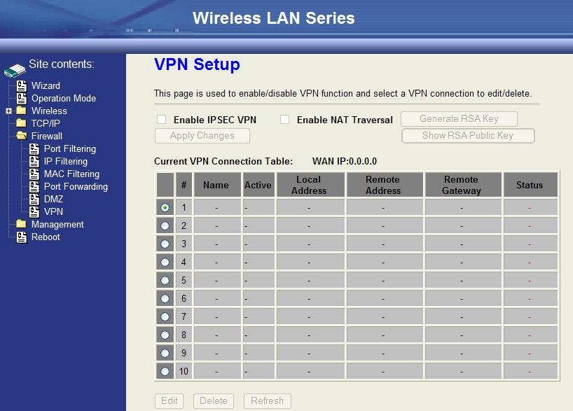
51 Configuring VPN 50
 to WAN or LAN to WLAN, but not WLAN to WLAN. Enable the QoS and then fill in the Bandwidth Ratio (H/M/L).")

52 Management Configuration Quality of Service (QoS) QoS allows you to specify some rules, to ensure the quality of service in your network, such as Bandwidth Priority to allocate bandwidth. This function can be helpful in shaping and queuing traffic from LAN (WLAN) to WAN or LAN to WLAN, but not WLAN to WLAN. Enable the QoS and then fill in the Bandwidth Ratio (H/M/L). The device has three Bandwidth Priorities High, Medium and Low. The user can allocate Bandwidth among these and the default is High:50%, Medium:30% and Low:20%. The following table describes the priorities that you can apply to bandwidth. Priority Level High Medium Low Description Typically used for voice or video applications that is especially sensitive to the variations in delay. Typically used for important traffic that can tolerate some delay. Typically used for non-critical traffic such as a large number of transfers but that should not affect other application. Click the QoS link under Management to open the QoS Setting page. This page is divided into three parts: basic settings, QoS rule settings, and current QoS setting table. Enable QoS and enter Max Throughput (default 20Mbps) Bandwidth Ratio (default H:50%, M:30%, L:20%) 51 Label Description

53 QoS Enabled Bandwidth Borrowed Max Throughput Select this check box to enable quality of service. Select this check box to allow a rule to borrow unused bandwidth. Bandwidth borrowing is decided by priority of the rules. Higher priority will get the remaining bandwidth first. Enter the value of max throughput in kbps that you want to allocate for one rule. The value should between 1200 kbps and kbps. Bandwidth Ratio (H/M/L) You can specify the ratio of priority in these fields. The range from 1 to 99. The High priority s ratio should higher than Medium priority s ratio and Medium priority s ratio should higher than Low priority s ratio. Apply Changes Click this button to save and apply your settings. QoS Rule settings Label IP Address Netmask MAC Address Port / range Protocol Bandwidth Priority Filter Priority IP TOS Match Apply Changes Reset Description Enter source/destination IP Address in dotted decimal notation. Once the source/destination IP Address is entered, the subnet mask address must be filled in this field. Enter source/destination MAC Address. You can enter specific port number or port range of the source/destination Select a protocol from the drop down list box. Choose TCP/UDP, TCP or UDP. Select a bandwidth priority from the drop down list box. Choose Low, Medium or High. Select a filter priority number from the drop down list box. Lower number gets higher priority while two rules have the same bandwidth priority. Select an IP type-of-service value from the drop down list box. Choose Normal Service, Minimize Cost, Maximize Reliability, Maximize Throughput, or Minimize Delay. Click this button to save and apply your settings. Click this button to begin re-input the parameters. Current QoS setting table In this part, you can see how many rules have been specified. In addition you can see the detail about the rules and manage 52


54 the rules. This table can handle 50 rules at most. An example for usage For example, there are three users in your network. User A wants to browse the websites to retrieve information. User B wants to use FTP connection to download a large file. User C wants to use software phone to connect with customer. Since VoIP traffic is sensitive to variations in delay (jitter), you can set High priority for User C. However, because the FTP transmission may take a long time, you can set Low priority for User B. Bandwidth Control This functionality can control the upstream and downstream bandwidth. Enable Bandwidth Control and then enter Data Rate Latency and Burst Packet in the specific field. 53

55 NOTE: Only device on Client mode or WISP mode this functionality can take effective. Parameter Definition Label Upstream Data Rate Upstream Latency Upstream Burst Packet Downstream Data Rate Downstream Latency Downstream Burst Packet Description Speed of transmit data that from Ethernet interface to Wireless interface. Similar a waiting time the data queuing- time. Similar a buffer the data will into the buffer while the data is transmit or receive. Speed of transmit data that from Wireless interface to Ethernet interface. Similar a waiting time the data queuing- time. Similar a buffer the data will into the buffer while the data is transmit or receive. SNMP Agent This device is compatible with SNMP v1/v2c and provides standard MIB II. Currently only the public community string is available and any setting modified by SNMP SET requests will be lost after rebooting the device. Enable SNMP and then enter IP Address of SNMP Manager in Trap Receiver IP Address field and Community String in System Community String field then click the Apply Changes button. 54

56 Following Table describes the SNMP configuration parameters Label System Community String System Name System Location System Contact Trap Receiver IP Address Trap Receiver Community String Description This is password sent with each trap to the SNMP Manager. Type the Name which is name of device. Type the Location which is location of device Type the Name which is person or group when the device has problem can find they. Type the IP Address which is address of SNMP Manager. This is password receive with trap from the device (SNMP Agent). SNMP Traps Traps coldstart(0) linkdown(2) linkup(3) authenticationfailure(4) Description The trap from device after reboot the device The trap is sent when any of the links are down. See the following table. The trap is sent when any of the links are UP. See the following table. The trap is sent when the device receiving gets or sets requirement with wrong community. Private MIBs OID Description Mode, Operation Mode in device SSID, SSID of the device Channel, Channel of the device in WLAN Band, g / b only RSSI, Receive Signal Strength Index (Support AP and Client RSSI) Active_Clients, The number of associate clients Active_Clients_List, Client s Information (MAC Address, Data Rate, RSSI etc) Encryption, Encryption type of device in Wireless Network 55
57 Mode SSID Channel Band RSSI Active_Clients Active_Clients_List Encryption 56
58 Upgrade Firmware Firmware Types The firmware for this device is divided into 2 parts, one is web pages firmware the other is application firmware, usually named g120webpage.bin and g120linux.bin. To upgrade the firmware, we suggest the user first upgrade the application firmware then the web pages firmware. Upgrading Firmware The Web-Browser upgrading interface is the simplest and safest way to upgrade the firmware. It will check the firmware checksum and signature, and the wrong firmware won t be accepted. After upgrading, the device will reboot. WARNING: Older versions of the firmware may cause the device configuration to be restored to the factory default setting upon rebooting and the original configuration data will be lost! To upgrade the firmware, just enter the file name with full path and click the Upload button. Memory Limitation To make sure the device has enough memory to upload firmware, the system will check the capacity of free memory. If the device lacks enough memory to upload the firmware, please temporarily turn-off some functions then reboot the device to get enough memory for firmware uploading. Save/Reload Settings Reset Setting to Factory Default Value Since the device is designed for outdoor use, there is no interface outside the housing to reset the configuration value to the factory default value. The device provides the Web-Browser interface to reset the configuration data. After resetting it, the current configuration data will be lost and restored to factory default value. 57
59 To save & restore configuration data of device, just enter the target filename with full path to your local host then you can back up the configuration data to local host or restore configuration data to the device. Password The Web-Browser interface has password protection. To disable the Web-Browser password protection just leave the User Name field to blank then click the Apply Changes button. 58
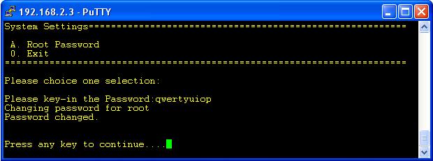
60 Using CLI Menu Start a SSH(Secure Shell) client session to login to the device The SSH server daemon inside the device uses TCP port 22. User must use SSH client utility such as Putty to login to the device. The default password for user root is either qwert or zplus depending on your firmware version. Once the user has logged in to the device, then the password can be changed by CLI command. Execute CLI program This program won t execute automatically when user logs in to the device. The user must manually execute it by typing the case-sensitive command cli. Please note that modified settings won t save permanently until the user executes Apply Changes to Flash and reboots the device. The new settings modified by CLI will take effect after rebooting the device. 59
61 Menu Tree List Operation Mode 1: Router 2: Bridge 0: Cancel Wireless Setting A. Basic Settings B. Advanced Settings C. Security Settings D. Access Control Settings E. WDS Settings 0. Exit A. Operation Mode B. Wireless Setting C. TCP/IP-LAN Setting D. TCP/IP-WAN Setting E. Route Setting F. Firewall Setting G. Management H. Apply Changes to Flash I. Reboot to take effect 0. Exit TCP/IP-LAN Setting A. IP Address B. Subnet Mask C. Default Gateway D. DHCP E. DHCP Client Range F d Spanning Tree G. Clone MAC Address H. MTU Size 0. Exit TCP/IP WAN Settings A. WAN Type B. IP Address C. Subnet Mask D. Default Gateway E. DNS1 F. DNS2 G. DNS3 Y. Clone MAC Address Z. upnp 0. Exit Route Settings -[Dynamic Route] A. Dynamic Route B. RIP transmit to WAN C. RIP receive from WAN D. RIP transmit to LAN E. RIP receive from LAN -[Static Route] F. Static Route G. Add Static Route Setting H. Delete Static Route Setting I. Delete all Static Route Setting J. Current Static Route Setting List -[Route Table] K. Show Route Table List 0. Exit Firewall Settings A. Port Filtering B. IP Filtering C. MAC Filtering D. Port Forwarding E. DMZ 0. Exit Wireless Basic Settings A. Access Point Status B. QoS Settings C. Bandwidth Control D. SNMP Settings E. Password 0. Exit Password The SSH Configuration interface has password protection. Please note that this password is separate from the web configuration password. 60
62 61

63 Auto Discovery Tool Auto Discovery can be used to find out how many devices are in your local area network The name of the tool is WirelessConf.exe. Discover After pressing this button, you will see how many devices are in your network and you would see the basic information about these devices, such as: SSID IP Address Subnet Mask Channel number MAC Address Setup IP After you press the Setup IP button, you will see Setup IP Address window. You can change the device s IP Address, Netmask, and Default Gateway in this window. But if the device s web server needs User Name and Password to login, you should fill in these two fields and then apply changes. 62


64 Detail If you want to see more detailed information, you could press the Detail button, and then you will see the Detail Information window. 63


65 WDS If the device you selected is in WDS mode or AP+WDS mode, you can press the WDS button and then you will see the WDS List window. Active Clients After pressing the Active Clients button, you will see the WLAN AP Active Clients window. with information, such as: Connect to Web Server If you want connect to device s web server you can press the Connect to Web Server button, or double-click on the device. 64
Wireless LAN Device Series. DLB2300-A User Manual
 Wireless LAN Device Series WLAN Outdoor Bridge DLB2300-A User Manual Version. 1.2.1 (25.03.2005) Table of Contents Preface...3 Ch 1. DLB2300A Installation...4 Packing List...4 Ch 2. First Time Configuration...5
MCPE-1924 User Manual. Version ( )
") MCPE-1924 User Manual Version. 1.2.2 (24.02.2006) TABLE OF CONTENTS PREFACE...3 CH 1. MCPE-1924 INSTALLATION...4 PACKING LIST...4 HARDWARE INSTALLATION...4 CH 2. FIRST TIME CONFIGURATION...6 BEFORE START
MCPE-1924 User Manual Version. 1.2.2 (24.02.2006) TABLE OF CONTENTS PREFACE...3 CH 1. MCPE-1924 INSTALLATION...4 PACKING LIST...4 HARDWARE INSTALLATION...4 CH 2. FIRST TIME CONFIGURATION...6 BEFORE START
Wireless LAN Device Series
 Wireless LAN Device Series WLAN Outdoor AP AP-G300 User Manual Version. 1.3.0.9a (2006.11.22) TABLE OF CONTENTS NOTICE...3 PREFACE...5 CH 1. AP-G300 INSTALLATION...6 AP-G300...6 Packing List...6 Hardware
Wireless LAN Device Series AP-G200. User Manual
 Wireless LAN Device Series AP-G200 Multi-Function WLAN AP User Manual Version 2.0 (November 2008) TABLE OF CONTENTS SAFETY AND REGULATORY NOTICES... 1 FCC STATEMENT... 1 FCC CAUTION... 1 FCC RF RADIATION
Security SSID Selection: Broadcast SSID:
 69 Security SSID Selection: Broadcast SSID: WMM: Encryption: Select the SSID that the security settings will apply to. If Disabled, then the device will not be broadcasting the SSID. Therefore it will
BOSSW221. User Manual
 BOSSW221 High Power Wireless Solution designed for Wireless ISP Service, Hot-Spot, and Backbone Max 400 mw with PoE & Radio 802.11b/g AP Client, AP Bridge, PtP Bridge, and WDS User Manual Congratulation
Wireless LAN Device Series. ZW-2000-IA User Manual
 Wireless LAN Device Series WLAN Outdoor Bridge ZW-2000-IA User Manual Version. TABLE OF CONTENTS PREFACE...3 CH 1. ZW-2000 INSTALLATION...4 PACKING LIST...4 HARDWARE INSTALLATION...5 CH 2. FIRST TIME CONFIGURATION...8
Light Mesh AP. User s Guide. 2009/2/20 v1.0 draft
 Light Mesh AP User s Guide 2009/2/20 v1.0 draft i FCC Certifications This equipment has been tested and found to comply with the limits for a Class B digital device, pursuant to Part 15 of the FCC Rules.
Wireless LAN Device Series CPE2615. User Manual. v
 Wireless LAN Device Series CPE2615 User Manual v20080312 Preface To use this guide, you should have experience working with the TCP/IP configuration and be familiar with the concepts and terminology of
Wireless LAN Device Series CPE2615. User Manual. v
 Wireless LAN Device Series CPE2615 User Manual v20081230 Preface To use this guide, you should have experience working with the TCP/IP configuration and be familiar with the concepts and terminology of
XG-520 Wireless b/g Portable Router. User s Manual
 XG-520 Wireless 802.11b/g Portable Router User s Manual FCC Certifications This equipment has been tested and found to comply with the limits for a Class B digital device, pursuant to Part 15 of the FCC
802.11a g Dual Band Wireless Access Point. User s Manual
 802.11a+802.11g Dual Band Wireless Access Point User s Manual 0 Chapter 1 Introduction 1.1 Feature Fully interoperable with IEEE 802.11b compliant products. High-Speed data transfer rate up to 11Mbps.
802.11a/b/g Access Point. User s Guide
 802.11a/b/g Access Point User s Guide FCC Certifications This equipment has been tested and found to comply with the limits for a Class B digital device, pursuant to Part 15 of the FCC Rules. These limits
WL-5450AP & WL-5460AP Wireless Access Point. User s Guide
 WL-5450AP & WL-5460AP Wireless Access Point User s Guide 1 FCC Certifications This equipment has been tested and found to comply with the limits for a Class B digital device, pursuant to Part 15 of the
WRT300N-DD User Manual
 WRT300N-DD User Manual Contents Features... 3 Configuring the Router... 3 1 Operation Mode... 8 2 Internet Settings... 8 2.1 WAN... 9 2.2 LAN... 13 2.3 DHCP clients... 15 2.4 Advanced Routing... 15 2.5
802.11b/g Access Point WL-8000AP
 802.11b/g Access Point WL-8000AP User s Guide - FCC Certifications This equipment has been tested and found to comply with the limits for a Class B digital device, pursuant to Part 15 of the FCC Rules.
AC750 Wireless Dual-Band Router CR2. User Manual
 AC750 Wireless Dual-Band Router CR2 User Manual Version 1.0 4/25/2014 Table of Content Chapter 1 Introduction... 3 1.1 Features... 3 1.2 System Requirement... 3 1.3 Package Contents... 4 Chapter 2 Hardware
CWA-854HT 54 Mbps Wireless-G High Transmission Access Point User s Guide
 CWA-854HT 54 Mbps Wireless-G High Transmission Access Point User s Guide May 2006 Version 1.00 1 Table of Contents Table of Contents... 2 List of Figures... 4 List of Tables... 6 Chapter 1. Introduction...
Wireless LAN Access Point
 Wireless LAN Access Point IEEE 802.11b/g 54Mbps 501903 User s Manual Table of Contents Chapter 1 Introduction... 1 1.1 Package Contents... 2 1.2 Features... 2 1.3 Specifications... 2 1.4 Physical Description...
WL-5420AP. User s Guide
 WL-5420AP User s Guide Table of contents INTRODUCTION... 1 About the Operation Modes...2 LED Indicators...5 Solid...5 Ports on the Rear Panel...7 GETTING CONNECTED... 8 WPA AP -CONFIGURATION VIA WEB...
Wireless LAN Access Point
 Wireless LAN Access Point IEEE 802.11b/g 54Mbps User s Manual Table of Contents Chapter 1 Introduction... 1 1.1 Package Contents... 2 1.2 Features... 2 1.3 Specifications... 2 1.4 Physical Description...
LevelOne User Manual WNC-0600USB N_One Wireless USB Adapter
 LevelOne User Manual WNC-0600USB N_One Wireless USB Adapter V2.0.0-0712 i Safety FCC WARNING This equipment has been tested and found to comply with the limits for a Class B digital device, pursuant to
Wireless LAN Access Point
 Wireless LAN Access Point IEEE 802.11b 11Mbps User s Manual Table of Contents Chapter 1 Introduction... 1 1.1 Package Contents... 2 1.2 Features... 2 1.3 Specifications... 2 1.4 Physical Description...
Figure 35: Active Directory Screen 6. Select the Group Policy tab, choose Default Domain Policy then click Edit.
 PC and Server Configuration Figure 35: Active Directory Screen 6. Select the Group Policy tab, choose Default Domain Policy then click Edit. Figure 36: Group Policy Tab 7. Select Computer Configuration
Wireless b/g Portable Router. User s Guide
 Wireless 802.11b/g Portable Router User s Guide FCC Certifications This equipment has been tested and found to comply with the limits for a Class B digital device, pursuant to Part 15 of the FCC Rules.
IEEE g Wireless PC Card. User s Guide
 IEEE 802.11g Wireless PC Card User s Guide FCC Certifications Federal Communication Commission Interference Statement This equipment has been tested and found to comply with the limits for a Class B digital
EZStation2 User Manual
 EZStation2 User Manual Rev. A 2.4GHz 400mW 802.11b/g Radio with 15dBi Patch Antenna Disclaimers No part of this documentation may be reproduced in any form or by any means or used to make any derivative
Wireless 11n Smart Repeater AP (1T1R)
") (1T1R) 2014 Table of Contents 1. Introduction...3 1.1 Package contents... 3 1.2 Product Features... 3 1.3 Front Panel Description... 4 1.4 Rear Panel Description... 5 2. Installation...6 2.1 Hardware Installation...
(1T1R) 2014 Table of Contents 1. Introduction...3 1.1 Package contents... 3 1.2 Product Features... 3 1.3 Front Panel Description... 4 1.4 Rear Panel Description... 5 2. Installation...6 2.1 Hardware Installation...
AC1200M/MS. User Manual
 AC1200M/MS User Manual Table of Contents User Manual... 1 1 Preface... 1 2 LED Indicators and Connectors... 1 2.1 LED Indicators... 1 2.2 Hardware Installation... 2 3 Voice Prompt (AC1200MS)... 2 4 User
PowerStation2 LiteStation2 LiteStation5 User s Guide
 PowerStation2 LiteStation2 LiteStation5 User s Guide Copyright 2007 Ubiquiti Networks Inc. All rights reserved. Contents INTRODUCTION...2 QUICK SETUP GUIDE...3 CONFIGURATION GUIDE...7 Main Settings...8
WH-9200AP a/b/g Dual Radio Wireless Base Station. User s Manual
 WH-9200AP 802.11a/b/g Dual Radio Wireless Base Station User s Manual Regulatory Information Federal Communication Commission Interference Statement This equipment has been tested and found to comply with
User Manual. OT-1044ns
 User Manual OT-1044ns CONTENTS Chapter 1 Introduction... 3 1.1 Features... 3 1.2 Environments... 3 1.3 System Requirement... 4 Chapter 2 Hardware Installation... 4 2.1 Led indicators... 4 2.2 Back Panel
User Manual Gemtek WiMAX Modem
 User Manual Gemtek WiMAX Modem WIXS-177 CONTENTS Chapter 1 Overview...1-1 1.1. Indoor CPE... 1-1 1.2. Outdoor CPE... 1-2 Chapter 2 WEB-GUI...2-3 2.1. System Configuration Login... 2-3 2.2. System Logout...
APC-100. IEEE g Wireless USB Adapter. User s Guide v1.0
 APC-100 IEEE 802.11g Wireless USB Adapter User s Guide v1.0 FCC Certifications Federal Communication Commission Interference Statement This equipment has been tested and found to comply with the limits
WL 5011s g Wireless Network Adapter Client Utility User Guide
 WL 5011s 802.11g Wireless Network Adapter Client Utility User Guide 10/2005 1 1. Introduction WL5011s client utility is a clean, straightforward GUI (Graphic User Interface) tool, which is designed for
IP806GA/GB Wireless ADSL Router
 IP806GA/GB Wireless ADSL Router 802.11g/802.11b Wireless Access Point ADSL Modem NAT Router 4-Port Switching Hub User's Guide DECLARATION OF CON FORMITY This device complies with Part 15 of the FCC Rules.
User s Guide. Model NO. CP500
 User s Guide Model NO. CP500 Table of Contents 1. Product Introduction... 3 1.1 Overview... 3 1.2 Features... 3 2. Hardware Installation... 4 2.1 Typical Application... 4 2.1.1 Point to Point... 4 2.1.2
2.4 GHz IEEE g 54Mbps Wireless LAN 2-WAY Access Point
 2.4 GHz IEEE 802.11g 54Mbps Wireless LAN 2-WAY Access Point GW-AP54SP CONTENTS Chapter 1 Introduction... 1 1.1 Features... 1 1.2 Parts Names and Functions... 2 1.3 Factory Default Settings... 3 Chapter
CE APPROVED.4 INTRODUCTION.5 PACKAGE CONTENTS. 6 PRE - INSTALLATION CHECKLIST. 6 SYSTEM REQUIREMENTS. 6 FEATURES AND BENEFITS.11 SETUP WIZARD.
 Web Edition Dec. 2002 Contents CE APPROVED...4 INTRODUCTION...5 PACKAGE CONTENTS... 6 PRE - INSTALLATION CHECKLIST... 6 SYSTEM REQUIREMENTS... 6 FEATURES AND BENEFITS... 7 4 - PORT CABLE/XDSL ROUTER...9
AIRNET 54Mb b/g High Power USB Adapter. User s Manual
 AIRNET 54Mb 802.11b/g High Power USB Adapter User s Manual FCC Certifications Federal Communication Commission Interference Statement This equipment has been tested and found to comply with the limits
Wireless G Broadband Travel user manual Model
 Wireless G Broadband Travel Router user manual Model 523875 INT-523875-UM-0807-03 Thank you for purchasing the INTELLINET NETWORK SOLUTIONS Wireless G Broadband Travel Router, Model 523875. This router
Table of Contents. Chapter 1Introduction Package Contents Features Specifications Physical Description...
 Table of Contents Chapter 1Introduction... 3 1.1 Package Contents... 3 1.2 Features... 3 1.3 Specifications... 3 1.4 Physical Description... 4 Chapter 2Wireless LAN Access Point Connection... 5 Chapter
802.11N Wireless Broadband Router
 802.11N Wireless Broadband Router Pre-N Wireless Access Point Broadband Internet Access WPS 4-Port Switching Hub User's Guide Table of Contents CHAPTER 1 INTRODUCTION... 1 Wireless Router Features... 1
WUG2690 User s Manual
 802.11b+g Wireless LAN USB Adapter WUG2690 User s Manual Federal Communication Commission Interference Statement This equipment has been tested and found to comply with the limits for a Class B digital
WISNETWORKS. WisOS 11ac V /3/21. Software version WisOS 11ac
 WISNETWORKS User Manual V1.1 2016/3/21 Software version 1.0.0021 Table of contents 1. Setup& WMI... 3 1.1 Hardware Setup... 3 1.2 Web Management Interface... 3 2. Status... 4 2.1 Overview... 4 2.1.1 System...
IP806GA/GB Wireless ADSL Router
 IP806GA/GB Wireless ADSL Router 802.11g/802.11b Wireless Access Point ADSL Modem NAT Router 4-Port Switching Hub User's Guide Table of Contents CHAPTER 1 INTRODUCTION... 1 Wireless ADSL Router Features...
11N Wireless PCI Adapter User Guide -6-
 -6- Copyright Statement is the registered trademark of Shenzhen Tenda Technology Co., Ltd. All the products and product names mentioned herein are the trademarks or registered trademarks of their respective
CERIO Corporation OW-310N2
 CERIO Corporation OW-310N2 1000mW extreme Power 11N 300Mbps Outdoor Access Point Quick Installation Guide 1. Overview CERIO OW-310N2 Outdoor AP Bridge utilizes a 1000mW high power with Aluminum Extrusion
Wireless-N Broadband AP / Router. User s Manual. Version 1.3
 Wireless-N Broadband AP / Router User s Manual Version 1.3 Federal Communication Commission Interference Statement This equipment has been tested and found to comply with the limits for a Class B digital
LevelOne WBR User s Manual. 11g Wireless ADSL VPN Router. Ver
 LevelOne WBR-3407 11g Wireless ADSL VPN Router User s Manual Ver 1.00-0510 Table of Contents CHAPTER 1 INTRODUCTION... 1 Wireless ADSL Router Features... 1 Package Contents... 5 Physical Details... 6 CHAPTER
Wireless Long Range Access Point / Client Bridge EOC5510. User Manual V1.0
 Wireless Long Range Access Point / Client Bridge EOC5510 User Manual V1.0 0 Table of Contents 1 PRODUCT OVERVIEW... 3 1.1 FEATURE... 3 1.2 BENEFITS... 5 1.3 PACKAGE CONTENTS... 6 1.4 SYSTEM REQUIREMENT...
Outdoor Wireless USB Adapter User Guide
 Outdoor Wireless USB Adapter User Guide FCC STATEMENT This equipment has been tested and found to comply with the limits for a Class B digital device, pursuant to part 15 of the FCC Rules. These limits
WL5041 Router User Manual
 TECOM WL5041 Router User Manual TECOM CO., LTD. March 2003 2003 by TECOM CO., LTD. All rights reserved. Printed in Taiwan Table of contents Package Contents--------------------------------------- 2 Installing
High Power g Wireless USB Adapter USER MANUAL 1.0.0
 High Power 802.11g Wireless USB Adapter USER MANUAL 1.0.0 2009 Table of Contents Chapter I USING THIS DOCUMENT 3 Chapter II INTRODUCTION 3 Chapter III SYSTEM REQUIREMENTS 3 Chapter IV Driver Installation
1. Package contents. 2. Connecting ADSL modem and wireless router
 1. Package contents WL-500W wireless router x 1 Power adapter x 1 Utility CD x 1 RJ45 cable x 1 Quick Start Guide x 1 2. Connecting ADSL modem and wireless router 1) Cable connection Wall power outlet
Wireless-G Router User s Guide
 Wireless-G Router User s Guide 1 Table of Contents Chapter 1: Introduction Installing Your Router System Requirements Installation Instructions Chapter 2: Preparing Your Network Preparing Your Network
300M Wireless-N Broadband Router User Manual
 300M Wireless-N Broadband Router Model No.: ib-wrb314n User Manual Ver.: 1.0.0 Contents...Error! Bookmark not defined. Chapter 1 Product Overview... 3 Package Contents 3 Conventions....4 Panel Overview...
ZAC Product Specification
 ZAC-1023-5-13 Part Number: ZN-7200-2AEI-L Product Specification IEEE 802.11 a/n CPE Version: 0.6-1 - 2 Specification 2.1 Hardware Specification Table 2-1 Hardware Specification Features Chipset Standard
RANGER SERIES. 150Mbps Wireless Green Broadband Router DG-BR4000NG. 150 Mbps V
 RANGER SERIES 150Mbps Wireless Green Broadband Router DG-BR4000NG N 150 Mbps V1.2 2011-12-15 FCC warning: This equipment has been tested and found to comply with the limits for a class B digital device,
EnGenius EAP N Multi-Function AP/Repeater
 EnGenius EAP9550 11N Multi-Function AP/Repeater Table of Content 1. Introduction...4 1.1. Features and Benefits...4 1.2. Package Contents...5 1.3. System Requirement...5 2. Understanding the Hardware...6
Dual Radio Concurrent AP/CB EOA7535 User Manual Version : 1.0
 Dual Radio Concurrent AP/CB EOA7535 User Manual Version : 1.0 Table of Contents 1 PRODUCT OVERVIEW... 3 1.1 BENEFITS... 3 1.2 FEATURE... 5 1.3 PACKAGE CONTENTS... 6 1.4 SYSTEM REQUIREMENT... 6 1.5 HARDWARE
EnGenius M2000 Wireless Outdoor Access Point / Client Bridge / Mesh User Manual Version: 1.0
 EnGenius M2000 Wireless Outdoor Access Point / Client Bridge / Mesh User Manual Version: 1.0 Table of Contents 1 INTRODUCTION... 6 1.1 FEATURES... 6 1.2 PACKAGE CONTENTS... 7 1.3 SYSTEM REQUIREMENTS...
U S E R M A N U A L b/g PC CARD
 U S E R M A N U A L 802.11b/g PC CARD Table of Content CHAPTER 1 INTRODUCTION... 1 1.1 WIRELESS LAN FEATURE FUNCTIONS... 1 1.2 REGULATORY NOTICE... 1 1.2.1 FCC Class B Statement...1 1.2.2 Canadian Regulatory
User Guide. For TP-Link Pharos Series Products
 User Guide For TP-Link Pharos Series Products CPE210 / CPE220 / CPE510 / CPE520 / CPE610 WBS210 / WBS510 1910012335 REV 3.0.1 March 2018 CONTENTS About this User Guide... 1 Overview... 2 1 Operation Modes...
Wireless Broadband Router
 LW6005A-R2 Wireless Broadband Router Manual 1 Introduction... 4 Features... 4 Minimum Requirements... 4 Package Content... 4 Note... 4 Get to know the Broadband Router... 5 Back Panel... 5 Front Panel...
FlyBoost CL100 USER MANUAL A02-OCL100 A02-OCL100_ME01
 FlyBoost CL100 A02-OCL100 USER MANUAL A02-OCL100_ME01 Table of Contents OVERVIEW THE PRODUCT... 1 Introduction... 1 Features and Benefits... 2 When to Use Which Mode... 3 Access Point Client Mode... 3
PRODUCT OVERVIEW. Learn more about EnGenius Solutions at
 Dual Radio Multi-Function Repeater 2.4 GHz / 5 GHz 300Mbps 802.11a/b/g/n Multi Function PRODUCT OVERVIEW equips with two powerful independent RF interfaces which support 802.11a/b/g and 802.11b/g/n. With
MIMO Wireless Broadband Route r User s Manual 1
 MIMO Wireless Broadband Router User s Manual 1 Introduction...4 Features...4 Minimum Requirements...4 Package Content...4 Note...4 Get to know the Broadband Router...5 Back Panel...5 Front Panel...6 Setup
High Power User's Manual of WLAN Broadband router USER MANUAL 1.0.1
 High Power User's Manual of WLAN Broadband router USER MANUAL 1.0.1 2010 Table of Contents Chapter I Terminology 5 Chapter II Introduction 7 1. Package... contents 7 2. Product... Specifications 7 3. Product...
Chapter 1 Introduction
 Copyright Statement is the registered trademark of Zonet Technology Inc. All the products and product names mentioned herein are the trademarks or registered trademarks of their respective holders. Copyright
airhaul Nexus sb3010
 u n w i r i n g o u r w o r l d TM airhaul Nexus sb3010 User Configuration Guide Version 1.3 Copyright smartbridges Pte Ltd. All Rights Reserved. About This Document This Software Configuration Guide is
Wireless LAN Card. User s Manual. Contents. A i
 A i Contents Wireless LAN Card User s Manual The user guide is fit for both Long Range Wireless LAN Card WPC- 8110 and Wireless LAN Card WPC-2110 CHAPTER 1. INTRODUCTION... 1 1.1 PACKAGE CONTENTS... 1
IEEE n Wireless PCI Adapter. User s Manual
 IEEE 802.11n Wireless PCI Adapter User s Manual October, 2008 FCC Warning This equipment has been tested and found to comply with the limits for a Class C digital device, pursuant to part 15 of the FCC
802.11g PC Card/USB Wireless Adapter
 802.11g PC Card/USB Wireless Adapter User Guide Regulatory Approvals FCC Statement This equipment has been tested and found to comply with the limits for a Class B digital device, pursuant to Part 15 of
Wireless 11n AP Router 1T1R
 Wireless 11n AP Router 1T1R Rev: 1.0.0rp FCC STATEMENT This equipment has been tested and found to comply with the limits for a Class B digital device, pursuant to part 15 of the FCC Rules. These limits
M5000 Wireless a/b/g Outdoor AP
 M5000 is a long range outdoor wireless Access Point / Client Bridge that operates in both 5 and 2.4 frequency. It provides high bandwidth up to 54Mbps and features high transmitted output power as well
EnGenius Quick Start Guide
 T he operates seamlessly in the 2.4 GHz frequency spectrum supporting the 802.11b (2.4GHz, 11Mbps) and the newer, faster 802.11g (2.4GHz, 54Mbpswireless standard. High output power and high sensitivity
Wireless Access Point
 802.11g / 802.11b / WPA Wireless Access Point User Guide TABLE OF CONTENTS CHAPTER 1 INTRODUCTION... 1 Features of your Wireless Access Point... 1 Package Contents... 4 Physical Details... 4 CHAPTER 2
Wireless Outdoor. Client Bridge / Access Point
 Wireless Outdoor Client Bridge / Access Point 2012 User Manual Version : 1.0 1 Product Overview Thank you for using ANSEL 2012. It is a powerful, enhanced, enterprise scale product with 4+1 multi-functions
Linksys E2000 Advanced Wireless-N Router. User Guide
 User Guide Table of Contents Contents Chapter 1: Product Overview 1 Top....................................................... 1 Back...................................................... 1 Horizontal
Wireless-B Broadband Router
 Wireless-B Broadband Router Version 1.0 Trademarks Microsoft, Windows, and Windows NT are registered trademarks of Microsoft Corporation. Other brand and product names are registered trademarks or trademarks
Section 3 - Configuration. Enable Auto Channel Scan:
 Enable Auto Channel Scan: Wireless Channel: The Auto Channel Scan setting can be selected to allow the DGL-4500 to choose the channel with the least amount of interference. Indicates the channel setting
LiteStation2 LiteStation5 User s Guide
 LiteStation2 LiteStation5 User s Guide Contents Contents... 2 Introduction... 3 Quick Setup Guide... 4 Configuration Guide... 8 Main Settings... 9 Link Setup... 10 Basic Wireless Settings... 10 Wireless
EOC1650. Wireless Access Point / Client Bridge / Client Router PRODUCT DESCRIPTION. 2.4GHz 54Mbps b/g Superior Performance
 Wireless Access Point / Client Bridge / Client Router 2.4GHz 54Mbps 802.11b/g Superior Performance PRODUCT DESCRIPTION is a revolutionary product consists of conciseness, quality, and flexibility. It comes
Wireless-N Pocket AP/Router ETR9360. Wireless N Pocket AP/Router V1.0
 Wireless-N Pocket AP/Router ETR9360 Wireless N Pocket AP/Router V1.0 1 1. Package Contents...5 2. System Requirements...5 3. Introduction...6 4. Features...7 5. Hardware Overview...8 6. Before you Begin...10
The VWRT510&WRT500 High Speed Router User s Guide
 The VWRT510&WRT500 High Speed Router User s Guide The page 1 of 53 Table of Contents 1 Preface... 4 2 LED Indicators and Connectors... 5 2.1 LED Indicators... 6 2.2 Hardware Installation... 7 3 Voice Prompt...
EOA7530. Dual Radio Concurrent AP/CB. 2.4GHz / 5GHz 54Mbps a/b/g Flexible Application
 Dual Radio Concurrent AP/CB EOA7530 2.4 / 5 54Mbps 802.11a/b/g Flexible Application EOA7530 equips with two powerful independent RF interfaces which support 802.11a and 802.11b/g. With certified IP-65
EOC2611P. Long Range Wireless Access Point / Client Bridge PRODUCT DESCRIPTION. 2.4GHz 108Mbps b/g/super G MSSID, WDS
 Long Range Wireless Access Point / Client Bridge 2.4GHz 108Mbps 802.11 b/g/super G MSSID, WDS PRODUCT DESCRIPTION is a long range outdoor wireless Access Point / Client Bridge that operates seamlessly
Wireless SOHO Router/Bridge 2.4 GHz b/g 54 Mbps
 Wireless SOHO Router/Bridge ECB-1220R 2.4 GHz 802.11 b/g 54 Mbps ECB-1220R is a 2.4GHz 802.11b/g broadband Wi-Fi Router with advanced AP/Client Bridge/Repeater functions. So you could implement this crossover
PRODUCT DESCRIPTION. Learn more about EnGenius Solutions at
 Wireless Long Range Multi-function Client Bridge 2.4 GHz EIRP up to 400mW Access point Client Bridge Repeater Client Router PRODUCT DESCRIPTION is a powerful client bridge. It supports several networking
Federal Communication Commission Interference Statement
 Federal Communication Commission Interference Statement This equipment has been tested and found to comply with the limits for a Class B digital device, pursuant to Part 15 of the FCC Rules. These limits
54M Wireless LAN CardBus Card
 54M Wireless LAN CardBus Card User s Manual Ver.2.0 Federal Communication Commission Interference Statement This equipment has been tested and found to comply with the limits for a Class B digital device,
EOC5611P. Wireless a/b/g Outdoor AP. Package Content PRODUCT DESCRIPTION. 2.4GHz / 5 GHz 54Mbps a/b/g 24V PoE
 Wireless 802.11 a/b/g Outdoor AP 2.4 / 5 54Mbps 802.11 a/b/g 24V PoE PRODUCT DESCRIPTION is a long range outdoor wireless Access Point / Client Bridge that operates in both 5 and 2.4 frequency. It provides
WLA-5000AP Access Point Mode
 WLA-5000AP Access Point Mode User s Guide Copyright Statement No part of this publication may be reproduced, stored in a retrieval system, or transmitted in any form or by any means, whether electronic,
802.11b+g Wireless LAN USB Adapter. User Manual
 802.11b+g Wireless LAN USB Adapter User Manual REGULATORY STATEMENTS FCC Certification The United States Federal Communication Commission (FCC) and the Canadian Department of Communications have established
High Power Wireless N USB Adapter User s Manual
 High Power Wireless N USB Adapter User s Manual 2 Table of Contents 1. Introduction... 4 1.1 Package Contents... 4 1.2 Features... 4 2. Installation... 5 3. Configuring the Adapter... 11 4. Wireless Utility...
TABLE OF CONTENT 1. ABOUT THIS GUIDE Overview of the User s Guide INTRODUCTION Overview Features...
 TABLE OF CONTENT 1. ABOUT THIS GUIDE... 3 1.1 Overview of the User s Guide... 3 2. INTRODUCTION... 3 2.1 Overview... 3 2.2 Features... 3 2.3 Panel Layout... 4 2.3.1 Front Panel... 4 2.3.2 Rear Panel...
ECB Gon Tel: +44 (0) Fax: +44 (0) Wireless Long Range Multi-function 7+1 AP
 Fax: +44 (0) Wireless Long Range Multi-function 7+1 AP") Wireless Long Range Multi-function 7+1 AP (Access Point/Client Bridge/Repeater/WDS AP/ WDS Bridge/ Client Router/AP Router) 2.4 GHz Super G 108Mbps EIRP up to 2000mW PRODUCT DESCRIPTION is a powerful,
Wireless Long Range Multi-function 7+1 AP (Access Point/Client Bridge/Repeater/WDS AP/ WDS Bridge/ Client Router/AP Router) 2.4 GHz Super G 108Mbps EIRP up to 2000mW PRODUCT DESCRIPTION is a powerful,
LevelOne. User Manual. WAP Mbps PoE Wireless AP V3.0.0
 LevelOne WAP-0005 108Mbps PoE Wireless AP User Manual V3.0.0 i TABLE OF CONTENTS CHAPTER 1 INTRODUCTION... 1 FIGURE 1: WIRELESS ACCESS POINT... 1 FEATURES OF YOUR WIRELESS ACCESS POINT... 1 Security Features...
M5000. Wireless a/b/g Outdoor AP PRODUCT DESCRIPTION
 Wireless 802.11 a/b/g Outdoor AP 2.4 / 5 54Mbps 802.11 a/b/g MESH Function PRODUCT DESCRIPTION is a long range outdoor wireless Access Point / Client Bridge that operates in both 5 and 2.4 frequency. It