Preface. Manual Revisions. Trademarks
|
|
|
- Lindsay Spencer
- 6 years ago
- Views:
Transcription
1
2 Preface D-Link reserves the right to revise this publication and to make changes in the content hereof without obligation to notify any person or organization of such revisions or changes. Manual Revisions Revision Date Description 1.00 June 30, 2015 Initial release for revision A1 Trademarks D-Link and the D-Link logo are trademarks or registered trademarks of D-Link Corporation or its subsidiaries in the United States or other countries. All other company or product names mentioned herein are trademarks or registered trademarks of their respective companies. Copyright 2015 by D-Link Corporation, Inc. All rights reserved. This publication may not be reproduced, in whole or in part, without prior expressed written permission from D-Link Corporation, Inc. i
3 Table of Contents Table of Contents Preface... i Package Contents... 1 System Requirements... 2 Introduction... 3 Features... 4 Hardware Overview... 5 Bottom Panel... 5 Physical Installation... 6 Before You Begin... 6 Safety Precautions... 7 Physical Installation... 8 Mounting the AP...10 Mounting the AP to a Pole...10 Mounting the AP to a Wall...11 Connect to your Network...12 Method 1 - Powered by PoE Switch...12 Method 2 - Powered by PoE Injector...13 Wireless Installation Considerations...14 Four Operational Modes...15 Configuration...16 Web-based Configuration Utility...16 Save and Activate Settings...17 Basic Settings...18 Wireless...18 Access Point mode...18 WDS with AP mode...20 WDS mode...22 Wireless Client mode...24 Authentication Types...26 Open System/Shared Key Authentication...26 WPA/WPA2-Personal Authentication...27 WPA/WPA2-Enterprise Authentication x Authentication...29 LAN...30 IPv Advanced Settings...32 Performance...32 Wireless Resource Control...34 Multi-SSID...36 VLAN...37 VLAN List...37 Port List...38 Add/Edit VLAN...39 PVID Setting...40 Intrusion...41 Schedule...42 Internal RADIUS Server...43 ARP Spoofing Prevention Settings...44 Bandwidth Optimization...45 AP Array...47 AP Array Scan...47 ii
4 Table of Contents Configuration Settings...48 Auto-RF...49 Load Balance...50 Captive Portal Authentication...51 Web Redirection Only...51 Username/Password...52 Passcode...53 Remote RADIUS...54 LDAP...55 POP Login Page Upload...58 IP Filter Settings...59 MAC Bypass...60 DHCP Server...61 Dynamic Pool Settings...61 Static Pool Setting...62 Current IP Mapping List...63 Filters...64 Wireless MAC ACL...64 WLAN Partition...65 Traffic Control...66 Uplink/Downlink Settings...66 QoS...67 Traffic Manager...68 Status...69 Device Information...69 Client Information...70 WDS Information...71 Channel Analyze...72 Statistics...73 Ethernet...73 WLAN Traffic...74 Log...75 View Log...75 Log Settings...76 Maintenance...78 Administration Settings...78 Limit Administrator...79 System Name Settings...80 Login Settings...81 Console Settings...82 SNMP Settings...83 Status:...84 Ping Control...84 Central WiFiManager Settings...85 Firmware and SSL Certification Upload...86 Configuration File Upload...87 Time and Date...88 System...89 System Settings...89 Help...90 Wireless Security...91 What is WEP?...92 Configure WEP...93 What is WPA?...94 Configure WPA/WPA2 Personal...95 Configure WPA/WPA2 Enterprise...96 iii
5 Table of Contents Connect to a Wireless Network...97 Using Windows XP...97 Configure WPA-PSK...98 Using Windows Vista Configure WPA-PSK Using Windows Troubleshooting Wireless Basics What is Wireless? Tips Wireless Modes Networking Basics Check your IP address Statically Assign an IP address Technical Specifications Antenna Pattern Central WiFiManager iv

6 Section 1 - Product Overview Package Contents DAP-3320 Wireless PoE Outdoor Access point Quick Installation Guide Wall mounting bracket with mounting kit with two plastic mounting ties Grounding Wire Note: A PoE Injector is not included with this Access Point. To power this device we suggest using a D-Link PoE Switch or a D-Link DPE-101GI PoE Injector. 1
7 Section 1 - Product Overview System Requirements Network Requirements An Ethernet-based Network IEEE n/g wireless clients (AP Mode) IEEE n/g wireless network (AP Mode) Computer with the following: Windows, Macintosh, or Linux-based operating system An installed Ethernet adapter Web-based Configuration Utility Requirements Browser Requirements: Microsoft Internet Explorer 8, Mozilla Firefox 28.0, Google Chrome 33.0, or Safari 5.1 or higher Windows Users: Make sure you have the latest version of Java installed. Visit to download the latest version. 2
8 Section 1 - Product Overview Introduction The D-Link DAP-3320 Wireless PoE Outdoor Access point is an n compliant device that delivers real world performance of up to 300 Mbps * while still maintaining backwards compatibility with slower g and b devices. The DAP-3320 increases productivity by allowing you to work faster and more efficiently. With the DAP-3320, bandwidth-intensive applications like graphics or multimedia will benefit significantly because large files are now able to move across the network more quickly. Create a secure wireless network to share photos, files, music, video, printers, and network storage outside of your normal internal networking environment. Built to withstand harsh environments, the DAP-3320 also excels in connecting separate networks that cannot be joined physically using a traditional medium. The built-in omni-directional 2 dbi antenna is designed to deliver high powered performance, ensuring that wireless coverage will cover even hard to reach locations. The DAP-3320 is an ideal solution for quickly creating and extending a wireless local area network (WLAN) in offices or other workplaces, hotels, resorts, trade shows, and special events. The DAP-3320 features four different operation modes: Access Point, Wireless Distribution System (WDS), WDS with AP, and Wireless Client mode, allowing it to adapt to many situations. As a standard wireless Access Point (AP) the DAP-3320 can connect to a wide range of devices that are n/g/b compliant. In WDS mode it can expand current wireless coverage without the need for a wired backbone link. As a wireless client it can connect to an existing AP, and expand the network physically with the built-in 10/100 Ethernet port. The DAP-3320 supports 64/128-bit WEP data encryption and WPA/WPA2 security functions. In addition, it provides MAC Address Filtering to control user access, and the Disable SSID Broadcast function to limit unauthorized access to the internal network. Network administrators have multiple options for managing the DAP-3320, including Web (HTTP) or Secured Web (HTTPS). For advanced network management, administrators can use SNMP v1, v2c, v3 to configure and manage access points. *Maximum wireless signal rate derived from IEEE Standard n and g specifications. Actual data throughput may vary. Network conditions and environmental factors, including volume of network traffic, building materials and construction, and network overhead can lower actual data throughout rate. 3
9 Section 1 - Product Overview Features Faster Wireless Networking - The DAP-3320 provides an up to 300 Mbps* wireless connection with other n wireless clients. This capability allows users to participate in real-time activities online, such as video streaming, online gaming, and real-time audio. Compatible with IEEE802.11g Devices - The DAP-3320 is still fully compatible with the g standards, so it can connect with existing g adapters. Four different operation modes - Capable of operating in one of four different operation modes to meet your wireless networking needs: Access Point, WDS with AP, WDS, and Wireless Client. Power over Ethernet - The DAP-3320 supports IEEE 802.3af PoE (Power over Ethernet) which enables it to be supplied with power over an Ethernet cable or IEEE 802.3af PoE switch. Comprehensive Web-Interface - Fine tune network settings using the DAP-3320 s robust network-based configuration software. Central WiFiManager management software compatibility - The real-time display of the network s topology and AP s information makes network configuration and management of multiple devices quick and simple. SNMP for management - The DAP-3320 supports SNMP v1, v2c, and v3 for better network management. Superior wireless AP manager software is bundled with the DAP-3320 for network configuration and firmware upgrade. Systems administrators can also set up the DAP-3320 easily with the Web-based configuration utility. Convenient Installation - The DAP-3320 features a wall/pole mount on the rear for easy setup on poles or walls. Weather Resistance - The DAP-3320 is built to withstand harsh environments, and is compliant with the IP55 Dust/ Water-proof standard. 4

10 Section 1 - Product Overview Hardware Overview Bottom Panel Reset button Hold the reset button for at least 5 seconds to reset the device back to the factory default settings. The LED will turn on for 2 seconds and then begin the reboot process. 2 LED A solid green light indicates the device is powered and operational /100 LAN (PoE) port Grounding Wire Screw Terminal Power is supplied to this port via a LAN cable that is connected to the PoE injector. Connect a grounding wire to help prevent device damage due to shorts and lightning strikes. 5
11 Section 2 - Installation Physical Installation Before You Begin This chapter describes safety precautions and product information that you must know and check before installing this product. Professional Installation Required 1. Please seek assistance from a professional installer who is well trained in RF installation and knowledgeable about local regulations. 2. This product is distributed through distributors and system installers with professional technicians and is not to be sold directly through retail stores. 6
12 Section 2 - Installation Safety Precautions To keep you safe and to install the hardware properly, please read and follow these safety precautions: 1. If you are installing an access point for the first time, for your safety as well as others, please seek assistance from a professional installer who has received safety training on the hazards involved. 2. Keep safety as well as performance in mind when selecting your installation site, especially when there are electric power and phone lines. 3. When installing your access point, note the following: Do not use a metal ladder. Do not work on a wet or windy day. Wear shoes with rubber soles and heels, rubber gloves, and a long sleeved shirt or jacket. 4. When the system is operational, avoid standing directly in front of the antenna. Strong RF fields are present when the transmitter is on. 5. A safety grounding system is necessary to protect your outdoor installation from lightning strikes and the build-up of static electricity. When mounting the product on an antenna mast, you must connect the product to the same grounding system as the AC wall outlet. The grounding system must comply with the National Electrical Code and safety standards that apply in your country. 6. Always check with a qualified electrician if you are in doubt as to whether your outdoor installation is properly grounded. 7
13 Section 2 - Installation Physical Installation Remove the bottom cover Lift the release tab in the middle of the cover, then pull the cover off. Connect an Ethernet cable Connect an Ethernet cable (not included) to the Ethernet port. 8
14 Section 2 - Installation Connect the grounding wire Use the grounding screw to attach the grounding wire. Reattach the bottom cover. You may need to break off one of the plastic port covers to allow your cables to exit the AP. 9
15 Section 2 - Installation Mounting the AP The DAP-3320 supports the IP55 water/dustproof standard. It is recommended that you place the AP under a roof, shelter, or weatherproof container in severe weather environments. It is highly recommended that you configure and test your access point before mounting it. Mounting the AP to a Pole Thread the plastic mounting ties through the back of the DAP-3320 and around the pole. 10
16 Section 2 - Installation Mounting the AP to a Wall Screw the wall mounting bracket into the wall, then attach the DAP-3320 to it. For extra security, you can thread the plastic mounting ties through the back of the DAP-3320 and the wall mounting bracket as shown. 11
 port on the DAP-3320 and then connect the other end to your PoE switch.")
17 Section 2 - Installation Connect to your Network To power the access point, you can use one of the following 2 methods: Method 1 - Powered by PoE Switch Method 2 - Powered by PoE Injector Method 1 - Powered by PoE Switch 1. Connect one end of your Ethernet cable into the LAN (PoE) port on the DAP-3320 and then connect the other end to your PoE switch. 12
18 Section 2 - Installation Method 2 - Powered by PoE Injector If you wish to power the DAP-3320 without a PoE switch, we suggest you use a PoE injector, such as a DPE-101GI. 1. Connect one end of an Ethernet cable into the DATA IN port on the PoE injector and the other end into a port on your switch, router, or computer. 2. Connect one end of a different Ethernet cable into the P+DATA OUT port on the PoE injector and the other end into the LAN (PoE) port on the DAP-3320 access point. 3. Connect the supplied power adapter to the POWER IN connector on the PoE Injector. 4. Plug the power adapter into a power outlet. 13
19 Section 2 - Installation Wireless Installation Considerations The D-Link DAP-3320 Wireless PoE Outdoor Access point lets you access your network using a wireless connection from virtually anywhere within the operating range of your wireless network. Keep in mind, however, that the number, thickness and location of walls, ceilings, or other objects that the wireless signals must pass through, may limit the range. Typical ranges vary depending on the types of materials and background RF (radio frequency) noise in your home or business. The key to maximizing wireless range is to follow these basic guidelines: 1. Keep the number of walls and ceilings between the D-Link access point and other network devices to a minimum. Each wall or ceiling can reduce your adapter s range from 3-90 feet (1-30 meters). Position your devices so that the number of walls or ceilings is minimized. 2. Be aware of the direct line between network devices. A wall that is 1.5 feet thick (.5 meters), at a 45-degree angle appears to be almost 3 feet (1 meter) thick. At a 2-degree angle it looks over 42 feet (14 meters) thick! Position devices so that the signal will travel straight through a wall or ceiling (instead of at an angle) for better reception. 3. Building materials make a difference. A solid metal door or aluminum studs may have a negative effect on range. Try to position access points, wireless access points, and computers so that the signal passes through drywall or open doorways. Materials and objects such as glass, steel, metal, walls with insulation, water (fish tanks), mirrors, file cabinets, brick, and concrete will degrade your wireless signal. 4. Keep your product away (at least 3-6 feet or 1-2 meters) from electrical devices or appliances that generate RF noise. 5. If you are using 2.4 Ghz cordless phones or X-10 (wireless products such as ceiling fans, lights, and home security systems), your wireless connection may degrade dramatically or drop completely. Make sure your 2.4 Hz phone base is as far away from your wireless devices as possible. The base transmits a signal even if the phone is not in use. 14
20 Four Operational Modes Operation Mode (Only supports 1 mode at a time) Access Point (AP) WDS with AP WDS Wireless Client Function Create a wireless LAN Wirelessly connect multiple networks while still functioning as a wireless AP Wirelessly connect multiple networks AP acts as a wireless network adapter for your Ethernet-enabled device 15

21 Configuration This section will show you how to configure your new D-Link Wireless PoE Outdoor Access point using the web-based configuration utility. Web-based Configuration Utility If you wish to change the default settings or optimise the performance of the DAP-3320, you may use the webbased configuration utility. To access the configuration utility, open a web browser such as Internet Explorer and enter Type admin and then enter your password. Leave the password blank by default. If you get a Page Cannot be Displayed error, please refer to Troubleshooting on page 106 for assistance. 16
22 After successfully logging into the DAP-3320, the following screen will appear: Save and Activate Settings When making changes on most of the configuration screens in this section, use the screen to save (not activate) your configuration changes. button at the bottom of each You may change settings to multiple pages before activating. Once you are finished, click the Configuration button located at the top of the page and then click Save and Activate. 17
23 Wireless Band: Select 2.4 Ghz from the drop-down menu. Basic Settings Wireless Access Point mode Mode: Select Access Point from the drop-down menu. The other three choices are WDS with AP, WDS, and wireless Client. Network Name (SSID): SSID Visibility: Auto Channel Selection: Channel: Service Set Identifier (SSID) is the name designated for a specific wireless local area network (WLAN). The SSID s factory default setting is dlink. The SSID can be easily changed to connect to an existing wireless network or to establish a new wireless network. The SSID can be up to 32 characters and is case-sensitive. Enable or Disable SSID visibility. Enabling this feature broadcasts the SSID across the network, thus making it visible to all network users. This feature is enabled by default. Enabling this feature automatically selects the channel that provides the best wireless performance. Enable is set by default. The channel selection process only occurs when the AP is booting up. All devices on the network must share the same channel. To change the channel, first toggle the Auto Channel Selection setting to Disable, and then use the drop-down menu to make the desired selection. Note: The wireless adapters will automatically scan and match the wireless settings. 18

24 Channel Width: Authentication: Allows you to select the channel width you would like to operate in. Select 20 MHz if you are not using any n wireless clients. Auto 20/40 MHz allows you to connect to both n and b/g wireless devices on your network. Use the drop-down menu to choose Open System, Shared Key, WPA- Personal, WPA-Enterprise, or x. Select Open System to communicate the key across the network. Select Shared Key to limit communication to only those devices that share the same WEP settings. If multi-ssid is enabled, this option is not available. Select WPA-Personal to secure your network using a password and dynamic key changes. No RADIUS server is required. Select WPA-Enterprise to secure your network with the inclusion of a RADIUS server. Select 802.1x to secure your network using 802.1x authentication. 19
25 WDS with AP mode In WDS with AP mode, the DAP-3320 wirelessly connects multiple networks while still functioning as a wireless AP. Wireless Band: Mode: Select 2.4 Ghz from the drop-down menu. WDS with AP mode is selected from the drop-down menu. The other three choices are Access Point, WDS, and wireless Client. Network Name (SSID): SSID Visibility: Auto Channel Selection: Channel: Channel Width: Remote AP MAC Address: Site Survey: Service Set Identifier (SSID) is the name designated for a specific wireless local area network (WLAN). The SSID s factory default setting is dlink. The SSID can be easily changed to connect to an existing wireless network or to establish a new wireless network. Enable or Disable SSID visibility. Enabling this feature broadcasts the SSID across the network, thus making it visible to all network users. Enabling this feature automatically selects the channel that will provide the best wireless performance. This feature is not supported in WDS with AP mode. The channel selection process only occurs when the AP is booting up. To change the channel, use the drop-down menu to make the desired selection. (Note: The wireless adapters will automatically scan and match the wireless settings.) Indicates whether the device is capable of 20 MHz operation only or both 20 MHz and 40 MHz operation. Enter the MAC addresses of the APs on your network that will serve as bridges to wirelessly connect multiple networks. Click on the Scan button to search for available wireless networks, then click on the available network that you want to connect with. 20

26 Authentication: Use the drop-down menu to choose Open System or WPA-Personal. Select Open System to communicate the key across the network. Select WPA-Personal to secure your network using a password and dynamic key changes. No RADIUS server is required. 21
27 WDS mode In WDS mode, the DAP-3320 wirelessly connects multiple networks, without functioning as a wireless AP. Wireless Band: Mode: Select 2.4 Ghz from the drop-down menu. WDS is selected from the drop-down menu. The other three choices are Access Point, WDS with AP, and wireless Client. Network Name (SSID): SSID Visibility: Auto Channel Selection: Channel: Channel Width: Remote AP MAC Address: Site Survey: Service Set Identifier (SSID) is the name designated for a specific wireless local area network (WLAN). The SSID s factory default setting is dlink. The SSID can be easily changed to connect to an existing wireless network or to establish a new wireless network. Enable or Disable SSID visibility. Enabling this feature broadcasts the SSID across the network, thus making it visible to all network users. Enabling this feature automatically selects the channel that will provide the best wireless performance. This feature is not supported in WDS with AP mode. The channel selection process only occurs when the AP is booting up. To change the channel, use the drop-down menu to make the desired selection. (Note: The wireless adapters will automatically scan and match the wireless settings.) Indicates whether the device is capable of 20 MHz operation only or both 20 MHz and 40 MHz operation. Enter the MAC addresses of the APs on your network that will serve as bridges to wirelessly connect multiple networks. Click on the Scan button to search for available wireless networks, then click on the available network that you want to connect with. 22
28 Authentication: Use the drop-down menu to choose Open System or WPA-Personal. Select Open System to communicate the key across the network. Select WPA-Personal to secure your network using a password and dynamic key changes. No RADIUS server is required. 23
29 Wireless Client mode Wireless Band: Mode: Select 2.4 Ghz from the drop-down menu. Wireless Client is selected from the drop-down menu. The other three choices are Access Point, WDS with AP, and WDS. Network Name (SSID): SSID Visibility: Auto Channel Selection: Channel: Channel Width: Service Set Identifier (SSID) is the name designated for a specific wireless local area network (WLAN). The SSID s factory default setting is dlink. The SSID can be easily changed to connect to an existing wireless network or to establish a new wireless network. Enable or Disable SSID visibility. Enabling this feature broadcasts the SSID across the network, thus making it visible to all network users. Disabling SSID is not supported in Wireless Client mode. Enabling this feature automatically selects the channel that will provide the best wireless performance. This feature is automatically enabled in Wireless Client mode. The channel selection process only occurs when the AP is booting up. To change the channel, use the drop-down menu to make the desired selection. (Note: The wireless adapters will automatically scan and match the wireless settings.) Indicates whether the device is capable of 20 MHz operation only or both 20 MHz and 40 MHz operation. Click on the Scan button to search for available wireless networks, then click on the available network that you want to connect with. 24

30 Authentication: Use the drop-down menu to choose Open System or WPA-Personal. Select Open System to communicate the key across the network. Select WPA-Personal to secure your network using a password and dynamic key changes. No RADIUS server is required. Wireless Mac Clone Enable: MAC Source: MAC Address: Check to enable clone MAC. This feature will allow you to change the MAC address of the access point to the MAC address of a client. Select the MAC source from the drop-down menu. Enter the MAC address that you would like to assign to the access point. 25

31 Authentication Types Each of the wireless modes on the DAP-3320 support different types of wireless encryption security standards. Not every mode supports all types of encryption. Open System/Shared Key Authentication All wireless modes on the DAP-3320 support Open System/Shared Key Authentication. Encryption Use the radio button to disable or enable encryption. Key Type: Select HEX * or ASCII **. Key Size: Key Index (1-4): Key: Select 64 Bits or 128 Bits. Select the 1st through the 4th key to be the active key: Input up to four keys for encryption. You will select one of these keys in the Key Index drop-down menu. *Hexadecimal (HEX) digits consist of the numbers 0-9 and the letters A-F. **ASCII (American Standard Code for Information Interchange) is a code that represents English letters using numbers ranging from
, WPA2 Only, or WPA Only.")
32 WPA/WPA2-Personal Authentication WPA/WPA2 Personal Authentication can be enabled for Access Point, WDS with AP, WDS, and Wireless Client modes. WPA Mode: When WPA-Personal is selected for Authentication type, you must also select a WPA mode from the drop-down menu: AUTO (WPA or WPA2), WPA2 Only, or WPA Only. WPA and WPA2 use different algorithms. AUTO (WPA or WPA2) allows you to use both WPA and WPA2. Cipher Type: Group Key Update: Periodical Key Change: PassPhrase: Confirm PassPhrase: When you select WPA-Personal, you must also select AUTO, AES, or TKIP from the drop-down menu. Select the interval during which the group key will be valid. The default value of 3600 is recommended. Select Manual to enter your key (PassPhrase). You can select Periodical Key Change to have the access point automatically change your PassPhrase. Enter the Activate From time and the time in hours to change the key. When you select WPA-Personal, please enter a PassPhrase in the corresponding field. Type the passphrase again to guard against typos. 27
, WPA2 Only, or WPA Only. WPA and WPA2 use different algorithms.")
33 WPA/WPA2-Enterprise Authentication WPA/WPA2 Enterprise Authentication can only be enabled for Access Point mode. WPA Mode: When WPA-Enterprise is selected, you must also select a WPA mode from the drop-down menu: AUTO (WPA or WPA2), WPA2 Only, or WPA Only. WPA and WPA2 use different algorithms. AUTO (WPA or WPA2) allows you to use both WPA and WPA2. Cipher Type: Group Key Update Interval: Network Access Protection: RADIUS Server: RADIUS Port: RADIUS Secret: When WPA-Enterprise is selected, you must also select a cipher type from the drop-down menu: Auto, AES, or TKIP. Select the interval during which the group key will be valid. The recommended value is A lower interval may reduce data transfer rates. Enable or disable Microsoft Network Access Protection. Enter the IP address of the RADIUS server. Enter the RADIUS port. Enter the RADIUS secret. 28
.")
34 802.1x Authentication 802.1x Authentication can only be enabled for Access Point mode. Key Update Interval: RADIUS Server: RADIUS Port: RADIUS Secret: Select the interval during which the group key will be valid (300 is the recommended value). A lower interval may reduce data transfer rates. Enter the IP address of the RADIUS server. Enter the RADIUS port. Enter the RADIUS secret. 29

35 LAN LAN is short for Local Area Network. This is considered your internal network. These are the IP settings of the LAN interface for the DAP These settings may be referred to as private settings. You may change the LAN IP address if needed. The LAN IP address is private to your internal network and cannot be seen on the Internet. Get IP From: IP Address: Subnet Mask: Default Gateway: DNS: Static IP (Manual) is chosen here. Choose this option if you do not have a DHCP server in your network, or if you wish to assign a static IP address to the DAP When Dynamic IP (DHCP) is selected, the other fields here will be grayed out. Please allow about two minutes for the DHCP client to be functional once this selection is made. The default IP address is Assign a static IP address that is within the IP address range of your network. Enter the subnet mask. All devices in the network must share the same subnet mask. Enter the IP address of the gateway in your network. If there is a gateway in your network, please enter an IP address within the range of your network. Enter the DNS IP address used here. 30
36 IPv6 Enable IPv6: Get IP From: IP Address: Prefix: Default Gateway: Check to enable the IPv6. Auto is the default option. The DAP-3320 will get an IPv6 address automatically or use Static to set IPv6 address manually. When Auto is selected, the other fields here will be grayed out. Enter the LAN IPv6 address used here. Enter the LAN subnet prefix length value used here. Enter the LAN default gateway IPv6 address used here. 31
37 Wireless: Advanced Settings Performance Use the drop-down menu to turn the wireless function On or Off. Wireless Mode: Data Rate*: Beacon Interval (25-500): DTM Interval (1-15): Transmit Power: The different combination of clients that can be supported include Mixed n, g and b, Mixed g and b and n Only. Please note that when backwards compatibility is enabled for legacy (802.11g/b) clients, degradation of n wireless performance is expected. Indicate the base transfer rate of wireless adapters on the wireless LAN. The AP will adjust the base transfer rate depending on the base rate of the connected device. If there are obstacles or interference, the AP will step down the rate. This option is enabled in Mixed g and b mode. The choices available are Best (Up to 54), 54, 48, 36, 24, 18, 12, 9, 6, 11, 5.5, 2 or 1. Beacons are packets sent by an access point to synchronize a wireless network. Specify a value in milliseconds. The default (100) is recommended. Setting a higher beacon interval can help to save the power of wireless clients, while setting a lower one can help a wireless client connect to an access point faster. Select a Delivery Traffic Indication Message setting between 1 and 15. The default value is 1. DTIM is a countdown informing clients of the next window for listening to broadcast and multicast messages. This setting determines the power level of the wireless transmission. Transmitting power can be adjusted to eliminate overlapping of wireless area coverage between two access points where interference is a major concern. For example, if wireless coverage is intended for half of the area, then select 50% as the option. Use the drop-down menu to select 100%, 50%, 25%, or 12.5%. *Maximum wireless signal rate derived from IEEE Standard n and g specifications. Actual data throughput may vary. Network conditions and environmental factors, including volume of network traffic, building materials and construction, and network overhead can lower actual data throughout rate. 32

38 WMM (Wi-Fi Multimedia): Ack Time Out (2.4 GHZ, 64~200): Short GI: IGMP Snooping: WMM stands for Wi-Fi Multimedia. Enabling this feature will improve the user experience for audio and video applications over a Wi-Fi network. To effectively optimize throughput over long distance links, enter a value for Acknowledgement Time Out from 64 to 200 microseconds in the 2.4 GHz in the field provided. Select Enable or Disable. Enabling a short guard interval can increase throughput. However, be aware that it can also increase the error rate in some installations due to increased sensitivity to radio-frequency installations. Select Enable or Disable. Internet Group Management Protocol allows the AP to recognize IGMP queries and reports sent between routers and an IGMP host (wireless STA). When IGMP snooping is enabled, the AP will forward multicast packets to an IGMP host based on IGMP messages passing through the AP. Multicast Rate: Select the multicast rate for 2.4G band. Multicast Bandwidth Control: Maximum Multicast Bandwidth : HT20/40 Coexistence: Transfer DHCP Offer to Unicast : Adjust the multicast packet data rate here. The multicast rate is supported in AP mode and WDS with AP mode, including Multi-SSIDs. Set the multicast packets maximum bandwidth pass through rate from the Ethernet interface to the Access Point. Enable this option to reduce interference from other wireless networks in your area. If the channel width is operating at 40 MHz and there is another wireless network s channel over-lapping and causing interference, the Access Point will automatically change to 20 MHz. Enable to transfer the DHCP Offer to Unicast from LAN to WLAN, it is recommended to enable this function if stations number is larger than
39 Wireless Resource Control The Wireless Resource Control window is used to configure the wireless connection settings so that devices can detect and connect to the Access Point with the strongest signal. Wireless band: Connection Limit: User Limit: 11n Preferred: Network Utilization: Aging out: Select 2.4 Ghz. Select Enable or Disable. This is an option for load balancing. This determines whether to limit the number of users accessing this device. The exact number is entered in the User Limit field below. This feature allows the user to share the wireless network traffic and the client using multiple APs. If this function is enabled and when the number of users exceeds this value, or the network utilization of this AP exceeds the percentage that has been specified, the DAP-3320 will not allow clients to associate with the AP. Set the maximum amount of users that are allowed access (zero to 64 users) to the device using the specified wireless band. The default setting is 20. Use the drop-down menu to Enable the 11n Preferred function. The wireless clients with n protocol will have higher priority to connect to the device. Set the maximum utilization of this access point. The DAP-3320 will not allow any new clients to associate with the AP if the utilization exceeds the specified value. Select a utilization percentage between 100%, 80%, 60%, 40%, 20%, or 0%. When this network utilization threshold is reached, the device will pause for one minute to allow network congestion to dissipate. Use the drop-down menu to select the criteria of disconnecting the wireless clients. Available options are RSSI and Data Rate. 34

40 RSSI Threshold: Data Rate Threshold: ACL RSSI: ACL RSSI Threshold: When RSSI is selected in the Aging out drop-down menu, select the percentage of RSSI here. When the RSSI of wireless clients is lower than the specified percentage, the device disconnects the wireless clients. When Data Rate is selected in the Aging out drop-down menu, select the threshold of data rate here. When the data rate of wireless clients is lower than the specified number, the device disconnects the wireless clients. Use the drop-down menu to Enable the function. When enabled, the device denies the connection request from the wireless clients with the RSSI lower than the specified threshold below. Set the ACL RSSI Threshold. 35

41 Multi-SSID The device supports up to four multiple Service Set Identifiers. In the Basic > Wireless section, you can set the Primary SSID. The SSID s factory default setting is dlink. The SSID can be easily changed to connect to an existing wireless network or to establish a new wireless network. Enable Multi-SSID: Check to enable support for multiple SSIDs. Band: This read-only value is the current band setting. Index: SSID SSID Visibility: Security: Priority: WMM (Wi-Fi Multimedia): You can select up to three multi-ssids. With the Primary SSID, you have a total of four multi-ssids. Service Set Identifier (SSID) is the name designated for a specific wireless local area network (WLAN). The SSID s factory default setting is dlink. The SSID can be easily changed to connect to an existing wireless network or to establish a new wireless network. Enable or Disable SSID visibility. Enabling this feature broadcasts the SSID across the network, thus making it visible to all network users. The Multi-SSID security can be Open System, WPA-Personal, WPA- Enterprise, or 802.1x. For a detailed description of the Open System parameters, please go to page 26. For a detailed description of the WPA- Personal parameters, please go to page 27. For a detailed description of the WPA-Enterprise parameters, please go to page 28. For a detailed description of the 802.1x parameters, please go to page 29. Check the Enable Priority box at the top of this window to enable. Select the priority from the drop-down menu. Select Enable or Disable. 36
, LAN, Primary Multiple SSID, and WDS connection can be assigned to VLANs as they are physical ports.")
42 VLAN VLAN List The DAP-3320 supports VLANs. VLANs can be created with a Name and VID. Mgmt (TCP stack), LAN, Primary Multiple SSID, and WDS connection can be assigned to VLANs as they are physical ports. Any packet which enters the DAP-3320 without a VLAN tag will have a VLAN tag inserted with a PVID. The VLAN List tab displays the current VLANs. VLAN Status: Use the radio button to toggle between Enable or Disable. Next, go to the Add/Edit VLAN tab to add or modify an item on the VLAN List tab. 37

43 Port List The Port List tab displays the current ports. If you want to configure guest and internal networks on a Virtual LAN (VLAN), the switch and DHCP server you are using must also support VLANs. As a prerequisite step, configure a port on the switch for handling VLAN tagged packets as described in the IEEE 802.1Q standard. VLAN Status: Port Name: Tag VID: Untag VID: PVID: Use the radio button to toggle to Enable. Next, go to the Add/Edit VLAN tab to add or modify an item on the VLAN List tab. The name of the port is displayed in this column. The Tagged VID is displayed in this column. The Untagged VID is displayed in this column. The Port VLAN Identifier is displayed in this column. 38
44 Add/Edit VLAN The Add/Edit VLAN tab is used to configure VLANs. Once you have made the desired changes, click the Save button to let your changes take effect. VLAN Status: Use the radio button to toggle to Enable. VLAN ID: VLAN Name: Provide an ID number between 1 and 4094 for the Internal VLAN. Enter the VLAN to add or modify. 39

45 PVID Setting The PVID Setting tab is used to enable/disable the Port VLAN Identifier Auto Assign Status as well as to configure various types of PVID settings. Click the Save button to let your changes take effect. VLAN Status: PVID Auto Assign Status: Use the radio button to toggle between Enable and Disable. Use the radio button to toggle PVID auto assign status to Enable. 40
46 Intrusion The Wireless Intrusion Protection window is used to set APs as All, Valid, Neighborhood, Rogue, and New. Click the Save button to let your changes take effect. AP List: Detect: The choices include All, Valid, Neighbor, Rogue, and New. Click this button to initiate a scan of the network. 41

47 Schedule The Wireless Schedule Settings window is used to add and modify scheduling rules on the device. Click the Save button to let your changes take effect. Wireless Schedule: Use the drop-down menu to enable the device s scheduling feature. Name: Index: SSID: Day(s): All Day(s): Start Time: End Time: Add: Schedule Rule List: Save: Enter a name for the new scheduling rule in the field provided. Select the SSID the schedule will apply to from the drop-down menu. Enter the name of your wireless network (SSID). Toggle the radio button between All Week and Select Day(s). If the second option is selected, check the specific days you want to apply the rule to. Check this box to have your settings apply 24 hours a day. Enter the start time for your rule. If you selected All Day, this option will be greyed out. Enter the end time for your rule. Click to add the rule to the list. This section will display the list of created schedules. Click the Save button to save your created rules. 42
48 Internal RADIUS Server The DAP-3320 features a built-in RADIUS server. Once you have finished adding a RADIUS account, click the Save button to have your changes take effect. The newly-created account will appear in this RADIUS Account List. The radio buttons allow the user to enable or disable the RADIUS account. Click the icon in the delete column to remove the RADIUS account. We suggest you limit the number of accounts to under 30. User Name: Password: Status: RADIUS Account List: Enter a name to authenticate user access to the internal RADIUS server. Enter a password to authenticate user access to the internal RADIUS server. The length of your password should be 8~64. Toggle the drop-down menu between Enable and Disable. Displays the list of users. 43

49 ARP Spoofing Prevention Settings The ARP Spoofing Prevention feature allows users to add IP/MAC address mapping to prevent ARP spoofing attacks. ARP Spoofing Prevention: Gateway IP Address: Gateway MAC Address: This check box allows you to enable the ARP spoofing prevention function. Enter a gateway IP address. Enter a gateway MAC address. 44
50 Bandwidth Optimization The Bandwidth Optimization window allows the user to manage the bandwidth of the access point and adjust the bandwidth for various wireless clients. After inputting a Bandwidth Optimization rule, click the Add button. To discard a Bandwidth Optimization Rule setting, click the Clear button. Click the Save button to let your changes take effect. Enable Bandwidth Optimization: Use the drop-down menu to Enable the Bandwidth Optimization function. Downlink Bandwidth: Uplink Bandwidth: Rule Type: Allocate average BW for each station: Allocate maximum BW for each station: Allocate different BW for b/g/n stations: Enter the downlink bandwidth of the device in Mbits per second. Enter the uplink bandwidth of the device in Mbits per second. Use the drop-down menu to select the type that is applied to the rule. Available options are: Allocate average BW for each station, Allocate maximum BW for each station, Allocate different BW for 11 b/g/n stations, and Allocte specific BW for SSID. AP will distribute average bandwidth for each client. Specify the maximum bandwidth for each connected client. Reserve certain bandwidth for future clients. The weight of 11 b/g/n client are 10%/20%/70%. AP will distribute different bandwidth for 11 b/g/n clients. 45
51 Allocate specific BW for SSID: Band: SSID Index: Downlink Speed: Uplink Speed: All clients share the total bandwidth. Use the drop-down menu to toggle the wireless band 2.4 Ghz. Use the drop-down menu to select the SSID for the specified wireless band. Enter the downlink speed limit in either Kbits/sec or Mbits/sec for the rule. Enter the upload speed limit in either Kbits/sec or Mbits/sec for the rule. 46

52 AP Array AP Array Scan The AP Array window is used to create up to 32 APs on a local network to be organized into a single group in order to simplify management. Click the Save button to let your changes take effect. Central WiFiManager and AP Array are mutually exclusive functions. Enable AP Array: AP Array Name: AP Array Password: Scan AP Array List: Connection Status: AP Array List: Current Members: Select the check box to enable the AP array function. The three modes that are available are Master, Backup Master, and Slave. APs in the same array will use the same configuration. The configuration will sync the Master AP to the Slave AP and the Backup Master AP when a Slave AP and a Backup Master AP join the AP array. Enter an AP array name for the group here. Enter an AP array password for the group here. This password must be the same on all the APs in the group. Click this button to initiate a scan of all the available APs currently on the network. Display the AP array connection status. This table displays the current AP array status for the following parameters: Array Name, Master IP, MAC, Master, Backup Master, Slave, and Total. This table displays all the current array members. The DAP-3320 AP array feature supports up to eight AP array members. 47

53 Configuration Settings In the AP array configuration settings windows, users can specify which settings all the APs in the group will inherit from the master AP. Make the desired selections in this window and click the Save button to accept the changes. Enable AP Array Configuration: Wireless Basic Settings: Wireless Advanced Settings: Multiple SSID & VLAN: Advanced Functions: Administration Settings: Select to Enable or Disable the AP array configure feature here. Select this option to specify the basic wireless settings that the APs in the group will inherit. Select this option to specify the advanced wireless settings that the APs in the group will inherit. Select this option to specify the multiple SSIDs and VLAN settings that the APs in the group will inherit. Select this option to specify the other advanced settings that the APs in the group will inherit. Select this option to specify the administrative settings that the APs in the group will inherit. 48
54 Auto-RF In this windows, users can view and configure the automatic radio frequency settings as well as configure the the auto-initiate period and threshold values. Click the Save button to accept the changes made. Enable: Auto-RF: Initiate Auto-RF: Auto-Initiate: Auto-Initiate Period: RSSI Threshold: RF Report Frequency: Select to Enable or Disable the auto-rf feature here. Click the Auto-RF Optimize button to initiate the auto-rf optimization feature. Select the Enable or Disable the auto-initiate feature here. After enabling the auto-initiate option, the auto-initiate period value can be entered here. This value must be between 1 and 24 hours. Select the RSSI threshold value here. This value is listed in the drop-down menu in increments of 10% from 10% to 100%. Enter the RF report frequency value here. 49
55 Load Balance In this window, users can view and configure the AP array s load balancing settings. Click the Save button to accept the changes made. Enable Load Balance: Active Threshold: Select to Enable or Disable the load balance feature here. Enter the active threshold value here. 50
56 Captive Portal Authentication Captive Portal is a built-in web authentication server. When a client connects to an AP, the user s web browser will be redirected to a web authentication page. In this configuration option, administrators can view and configure the Captive Portal settings. Web Redirection Only After selecting Web Redirection Only as the Authentication Type, admininstrators can configure the redirection website URL that each wireless client will be redirected to upon connection to the network. Session timeout (1-1440): Band: SSID Index: Authentication Type: Web Redirection State: Enter the session timeout value here. This value can be from 1 to 1440 minutes. By default, this value is 60 minutes. Select 2.4 Ghz. Select the SSID for this Authentication. Select the captive portal encryption type here. Options to choose from are Web Redirection, Username/Password, Passcode, Remote RADIUS, LDAP and POP3. Web Redirection State is automatically enabled when Web Redirection Authentication is selected. URL Path : Select whether to use either HTTP or HTTPS here. After selecting either or enter the URL of the website that will be used in the space provided. 51
: Band: SSID Index: Authentication Type: Web Redirection State: Enter the session timeout value here. This value can be from 1 to 1440 minutes.")
57 Username/Password After selecting Username/Password as the Authentication Type, administrators can configure the Username and Password that each wireless client will be prompted for when requesting access to the network. Session timeout (1-1440): Band: SSID Index: Authentication Type: Web Redirection State: Enter the session timeout value here. This value can be from 1 to 1440 minutes. By default, this value is 60 minutes. Select 2.4 Ghz. Select the SSID for this Authentication. Select the captive portal encryption type here. Options to choose from are Web Redirection, Username/Password, Passcode, Remote RADIUS, LDAP and POP3. Default is Disable or select Enable to enable the website redirection feature. URL Path : Select whether to use either HTTP or HTTPS here. After selecting either or enter the URL of the website that will be used in the space provided. Username: Enter the username for the new account here. Password: Enter the password for the new account here. 52
: Band: SSID Index: Authentication Type: Web Redirection State: Enter the session timeout value here.")
58 Passcode After selecting Passcode as the Authentication Type, administrators can configure the Passcode that each wireless client will be prompted for when requesting access to the network. A passcode will be randomly generated upon clicking Add. Session timeout (1-1440): Band: SSID Index: Authentication Type: Web Redirection State: Enter the session timeout value here. This value can be from 1 to 1440 minutes. By default, this value is 60 minutes. Select 2.4 Ghz. Select the SSID for this Authentication. Select the captive portal encryption type here. Options to choose from are Web Redirection, Username/Password, Passcode, Remote RADIUS, LDAP and POP3. Default is Disable or select Enable to enable the website redirection feature. URL Path : Select whether to use either HTTP or HTTPS here. After selecting either or enter the URL of the website that will be used in the space provided. Passcode Quantity: Duration: Last Active Day: User Limit: Enter the number of available passcodes Enter the duration value, in hours, for this passcode. Select the year, month, day, and hour when this passcode will expire. Enter the maximum amount of users that can use this passcode at the same time 53
: Band: SSID Index: Authentication Type: Web Redirection State: Enter the session timeout value here. This value can be from 1 to 1440 minutes.")
59 Remote RADIUS After selecting Remote RADIUS as the Authentication Type, administrators can configure the Remote RADIUS authentication settings required to join the network. Session timeout (1-1440): Band: SSID Index: Authentication Type: Web Redirection State: Enter the session timeout value here. This value can be from 1 to 1440 minutes. By default, this value is 60 minutes. Select 2.4 Ghz. Select the SSID for this Authentication. Select the captive portal encryption type here. Options to choose from are Web Redirection, Username/Password, Passcode, Remote RADIUS, LDAP and POP3. Default is Disable or select Enable to enable the website redirection feature. URL Path : Select whether to use either HTTP or HTTPS here. After selecting either or enter the URL of the website that will be used in the space provided. Radius Server: Radius Port: Radius Port: Remote Radius Type: Enter the RADIUS server s IP address here Enter the RADIUS server s port number here Enter the RADIUS server s shared secret here Select the remote RADIUS server type here. 54
60 LDAP After selecting LDAP as the Authentication Type, administrators can configure the LDAP authentication settings required to join the network. Session timeout (1-1440): Enter the session timeout value here. This value can be from 1 to 1440 minutes. By default, this value is 60 minutes. Band: SSID Index: Authentication Type: Web Redirection State: Select 2.4 Ghz. Select the SSID for this Authentication. Select the captive portal encryption type here. Options to choose from are Web Redirection, Username/Password, Passcode, Remote RADIUS, LDAP and POP3. Default is Disable or select Enable to enable the website redirection feature. URL Path : Select whether to use either HTTP or HTTPS here. After selecting either or enter the URL of the website that will be used in the space provided. Server: Port: Authenticate Mode: Username: Password: Enter the LDAP server s IP address or domain name here. Enter the LDAP server s port number here. Select the authentication mode here. Options to choose from are Simple and TLS. Enter the LDAP server account s username here. Enter the LDAP server account s password here. 55

61 Base DN: Account Attribute: Identity: Enter the administrator s domain name here Enter the LDAP account attribute string here. This string will be used to search for clients. Enter the identity s full path string here. Alternatively, select the Auto Copy checkbox to automatically add the generic full path of the web page in the identity field. 56
: Band: SSID Index: Authentication Type: Web Redirection State: Enter the session timeout value here. This value can be from 1 to 1440 minutes.")
62 POP3 After selecting POP3 as the Authentication Type, administrators can configure the POP3 authentication settings required to join the network. Session timeout (1-1440): Band: SSID Index: Authentication Type: Web Redirection State: Enter the session timeout value here. This value can be from 1 to 1440 minutes. By default, this value is 60 minutes. Select 2.4 Ghz. Select the SSID for this Authentication. Select the captive portal encryption type here. Options to choose from are Web Redirection, Username/Password, Passcode, Remote RADIUS, LDAP and POP3. Default is Disable or select Enable to enable the website redirection feature. URL Path : Select whether to use either HTTP or HTTPS here. After selecting either or enter the URL of the website that will be used in the space provided. Server: Port: Connection Type: Enter the POP3 server s IP address or domain name here. Port: Enter the POP server s port number here. Select the connection type here; either None or SSL/TLS. 57
63 Login Page Upload In this window, users can upload a custom login page picture that will be used by the captive portal feature. Click the Browse button to navigate to the image file, located on the managing computer and then click the Upload button to initiate the upload. Upload picture from file: Login Page Style List: In this field the path to the image file, that will be uploaded, will be displayed. Alternatively, the path can be manually entered here. Select the wireless band and login style that will be used for each SSID. Click the Download button to download the login page template file and Click the Del button to delete the template file. 58

64 IP Filter Settings Enter the IP address or network address that will be used in the IP filter rule. For example, an IP address like or a network address like This IP address or network will be inaccessible to wireless clients on this network. Wireless Band: IP Address: Subnet Mask: Upload IP Filter File: Download IP Filter File: Select the wireless band for MAC Bypass. Enter the IP address or network address. Enter the subnet mask of the IP address or networks address. To upload an IP filter list file, click Browse and navigate to the IP filter list file saved on your computer, and then click Upload. To download IP Filter list file, click Download and to save the IP Filter list. 59

65 MAC Bypass The DAP-3320 features a wireless MAC Bypass. Once a MAC address is added to the bypass list, that client will skip the Captive Portal Authentication process when joining a network. Once an administrator is finished adjusting these settings, click the Save button to have the changes take effect. Wireless Band: Select the wireless band for MAC Bypass. SSID Index: Select the SSID for MAC Bypass. MAC Address: MAC Address List: Enter each MAC address that you wish to include in your bypass list and then click Add. When a MAC address is entered, it appears in this list. Highlight a MAC address and click the Delete icon to remove it from this list. Upload File: To upload a MAC bypass list file, click Browse and navigate to the MAC bypass list file saved on the managing computer, and then click Upload. Load MAC File to Local Hard Drive: Click Download to save the MAC bypass list file. 60

66 DHCP Server Dynamic Pool Settings The DHCP address pool defines the range of the IP addresses that can be assigned to stations in the network. A Dynamic Pool allows wireless stations to receive an available IP with lease time control. If needed or required in the network, the DAP-3320 is capable of acting as a DHCP server. Function Enable/ Disable: IP Assigned From: IP Pool Range (1-254): Subnet Mask: Gateway: WINS: DNS: Domain Name: Lease Time : Dynamic Host Configuration Protocol (DHCP) assigns dynamic IP addresses to devices on the network. This protocol simplifies network management and allows new wireless devices to receive IP addresses automatically without the need to manually assign new IP addresses. Select Enable to allow the DAP-3320 to function as a DHCP server. Input the first IP address available for assignment on your network. Enter the number of IP addresses available for assignment. IP addresses are increments of the IP address specified in the IP Assigned From field. All devices in the network must have the same subnet mask to communicate. Enter the submask for the network here. Enter the IP address of the gateway on the network. Specify the Windows Internet Naming Service (WINS) server address for the wireless network. WINS is a system that determines the IP address of a network computer that has a dynamically assigned IP address. Enter the IP address of the Domain Name System (DNS) server. The DNS server translates domain names such as into IP addresses. Enter the domain name of the network, if applicable. (An example of a domain name is: The lease time is the period of time before the DHCP server will assign new IP addresses. ( sec) 61
67 Static Pool Setting A static pool allows specific IP addresses to be reserved to wireless stations. Function Enable/ Disable: Assigned IP: Assigned MAC Address: Subnet Mask: Gateway: WINS: DNS: Domain Name: Dynamic Host Configuration Protocol (DHCP) assigns IP addresses to wireless devices on the network. This protocol simplifies network management and allows new wireless devices to receive IP addresses automatically without the need to manually assign IP addresses. Select Enable to allow the DAP-3320 to function as a DHCP server. Use the Static Pool Settings to reserve IP addresses to specific devices. The IP addresses assigned in the Static Pool list must NOT be in the same IP range as the Dynamic Pool. After you have assigned a static IP address to a device via its MAC address, click Save; the device will appear in the Assigned Static Pool at the bottom of the screen. You can edit or delete the device in this list. Enter the MAC address of the device requesting association here. Define the submask of the IP address specified in the IP Assigned From field. Specify the Gateway address for the wireless network. Specify the Windows Internet Naming Service (WINS) server address for the wireless network. WINS is a system that determines the IP address of a network computer with a dynamically assigned IP address, if applicable. Enter the Domain Name System (DNS) server address for the wireless network. The DNS server translates domain names such as into IP addresses. Specify the domain name for the network. 62
68 Current IP Mapping List This window displays information about the current assigned DHCP dynamic and static IP address pools. This information is available when you enable DHCP server on the AP and assign dynamic and static IP address pools. Current DHCP Dynamic Profile: Host Name: Binding MAC Address: Assigned IP Address: Lease Time: Current DHCP Static Pools: Host Name: Binding MAC Address: Assigned IP Address: These are IP address pools the DHCP server has assigned using the dynamic pool setting. The host name of a device on the network that is assigned an IP address from the DHCP dynamic pool. The MAC address of a device on the network that is assigned an IP address from the DHCP dynamic pool. The current corresponding DHCP-assigned IP address of the device. The length of time that the dynamic IP address will be valid. These are the IP address pools of the DHCP server assigned through the static pool settings. The host name of a device on the network that is assigned an IP address from the DHCP dynamic pool. The MAC address of a device on the network that is within the DHCP static IP address pool. The current corresponding DHCP-assigned static IP address of the device. 63

69 Filters Wireless MAC ACL Wireless Band: Access Control List: MAC Address: MAC Address List: Upload ACL File: Displays the current wireless band rate. Select Disable to disable the filters function. Select Accept to accept only those devices with MAC addresses in the Access Control List. All other devices not on the list will be rejected. Select Reject to reject the devices with MAC addresses on the Access Control List. All other devices not on the list will be accepted. Enter each MAC address that you wish to include in your filter list, and click Add. When you enter a MAC address, it appears in this list. Highlight a MAC address and click Delete to remove it from this list. You may create an ACL list and upload it to the access point instead of manually entering the information. Once created, click the Browse button and locate your file. Select it and then click Upload. Download ACL File: Click Download to export the ACL to a file on your computer. 64

70 WLAN Partition Wireless Band: Link Integrity: Ethernet to WLAN Access: Internal Station Connection: Displays the current wireless band rate. Select Enable or Disable. The default is Enable. When disabled, all data from the Ethernet port to associated wireless devices will be blocked. Wireless devices can still send data to the Ethernet port. The default value is Enable, which allows stations to inter-communicate by connecting to a target AP. When disabled, wireless stations cannot exchange data through the AP. 65

71 Traffic Control Uplink/Downlink Settings The uplink/downlink setting allows users to customize the downlink and uplink interfaces including specifying downlink/uplink bandwidth rates in Mbits per second. These values are also used in the QoS and Traffic Manager windows. Once the desired uplink and downlink settings have been selected, click the Save button to let your changes take effect. Downlink Bandwidth: Uplink Bandwidth: The downlink bandwidth in Mbits per second. The uplink bandwidth in Mbits per second. 66

72 QoS Quality of Service (QoS) enhances the experience of using a network by prioritizing the traffic of different applications. A QoS Rule identifies a specific message flow and assigns a priority to that flow. For most applications, the priority classifiers ensure the right priorities and specific QoS Rules are not required. QoS supports overlaps between rules. If more than one rule matches a specific message flow, the rule with the highest priority will be used. QoS (Quality of Service): HTTP: Automatic: Enable this option if you want to allow QoS to prioritize your traffic Priority Classifiers. Allows the access point to recognize HTTP transfers for many common audio and video streams and prioritize them above other traffic. Such streams are frequently used by digital media players. When enabled, this option causes the access point to automatically attempt to prioritize traffic streams that it does not otherwise recognize, based on the behavior that the streams exhibit. This acts to de-prioritize streams that exhibit bulk transfer characteristics, such as file transfers, while leaving interactive traffic, such as gaming or VoIP, running at a normal priority. 67

73 Traffic Manager The traffic manager feature allows users to create traffic management rules that specify how to deal with listed client traffic and specify downlink/uplink speed for new traffic manager rules. Click the Save button to let your changes take effect. Traffic Manager: Unlisted Client Traffic: Downlink Bandwidth: Uplink Bandwidth: Use the drop-down menu to Enable the traffic manager feature. Select Deny or Forward to determine how to deal with unlisted client traffic. The downlink bandwidth in Mbits per second. This value is entered in the Uplink/Downlink Setting window. The uplink bandwidth in Mbits per second. This value is entered in the Uplink/ Downlink Setting window. 68

74 Status Device Information This read-only window displays the configuration settings of the DAP-3320, including the firmware version and the device's MAC address. 69
75 Client Information This window displays the wireless client information for clients currently connected to the DAP The following information is available for each client communicating with the DAP SSID: MAC: Band: Authentication: Signal: Power Saving Mode: Displays the SSID of the client. Displays the MAC address of the client. Displays the wireless band that the client is connected to. Displays the type of authentication being used. Displays the client's signal strength. Displays the status of the power saving feature. 70
76 WDS Information This window displays the Wireless Distribution System information for clients currently connected to the DAP The following information is available for each client communicating with the DAP Name: MAC: Authentication: Signal: Status: Displays the SSID of the client. Displays the MAC address of the client. Displays the type of authentication being used. Displays the client's signal strength. Displays the status of the power saving feature. 71

77 Channel Analyze Wireless Band: Detect: AP List: 2.4 Ghz Click the Detect button to scan. This will list the transmitting channels and quality. 72
78 Statistics Ethernet This page displays transmitted and received count statistics for packets and bytes. 73

79 WLAN Traffic This page displays wireless network statistics for data throughput, transmitted and received frames, and frame errors. 74
80 Log View Log The AP s embedded memory displays system and network messages including a time stamp and message type. The log information includes but is not limited to the following items: cold start AP, upgrading firmware, client associate and disassociate with AP, and web login. The web page holds up to 500 logs. 75
81 Log Settings Log Server/ IP Address: Log Type: EU directive Syslog Server Settings: Notification: Outgoing Mail Server (SMTP): Authentication: SSL / TLS: From Address: To Address: Server Address: SMTP Port: Username: Enter the IP address of the server you would like to send the DAP-3320 log to. Check the box for the type of activity you want to log. There are three types: System Activity, Wireless Activity, and Notice. Enter the EU Directive Log Server IP Address. Check to enable notification. Select the SMTP server from the drop-down menu. Check to enable authentication. Check to enable SSL/TLS authentication. Enter the From address. Enter the destination address. Enter the Server Address. Enter the SMTP port. Enter your username. 76
.")
82 Password: Confirm Password: Schedule: Enter your password. Enter your password again. Select when to send the log to your (in hours). You will receive an when the log is full too. 77
83 Maintenance Administration Settings Check one or more of the five main categories to view the various hidden administrator parameters and settings displayed on the next five pages. 78

84 Limit Administrator Each of the five main categories display various hidden administrator parameters and settings. Limit Administrator VLAN ID: Limit Administrator IP: IP Range: Check the box provided and the enter the specific VLAN ID that the administrator will be allowed to log in from. Check to enable the Limit Administrator IP address. Enter the IP address range that the administrator will be allowed to log in from and then click the Add button. 79

85 System Name Settings Each of the five main categories display various hidden administrator parameters and settings. System Name: Location The name of the device. The default name is D-Link DAP The physical location of the device, e.g. 72nd Floor, D-Link HQ. 80

86 Login Settings Each of the five main categories display various hidden administrator parameters and settings. Login Name: Old Password: New Password: Confirm Password: Enter a user name. The default is admin. When changing your password, enter the old password here. When changing your password, enter the new password here. The password is case-sensitive. A is a different character than a. The length should be between 0 and 12 characters. Enter the new password a second time for confirmation purposes. 81
87 Console Settings Each of the five main categories display various hidden administrator parameters and settings. Status: Status is enabled by default. Uncheck the box to disable the console. Console Protocol: Timeout: Select the type of protocol you would like to use, Telnet or SSH. Set to 1 Min, 3 Mins, 5 Mins, 10 Mins, 15 Mins or Never. 82

88 SNMP Settings Each of the five main categories display various hidden administrator parameters and settings. Status: Public Community String: Private Community String: Trap Status: Check the box to enable the SNMP functions. This option is disabled by default. Enter the public SNMP community string. Enter the private SNMP community string. Check the box to enable Trap Status. Trap Server IP: Enter the Trap Server IP address. 83

89 Ping Control Status: Check the box to enable Ping control. Ping works by sending ICMP echo request packets to the target host and listening for ICMP echo response replies. The default is enabled. If not enabled, the access point will not reply to pings. 84
90 Central WiFiManager Settings The Central WiFiManager section is used to configure and manage a set of APs on a network into a single group in order to simplify management. Central WiFiManager and AP Array may not be used simultaneously. Enable Central WiFiManager: Select to enable or disable the Central WiFiManager. 85

91 Firmware and SSL Certification Upload This page allows the user to perform a firmware upgrade. Be sure to check the support.dlink.com website periodically for the latest firmware updates to keep your product up to date with the latest features. Upload Firmware From Local Hard Drive: Language Pack Upgrade: Upload SSL Certification From Local Hard Drive: The current firmware version is displayed above the file location field. After downloading the most recent version of the firmware for the DAP-3320 from to your local computer, use the Browse button to locate the firmware file on your computer. Click Upload to update the firmware version. Please don t turn the power off while upgrading. You may load a language pack to display the utility in another language. Click Browse to locate the language pack file on your local computer. After selecting and opening the file, click Upload to upload the file to the DAP Click Browse to locate the SSL Certification file on your local computer. After selecting and opening the file, click Upload to upload the file to the DAP
92 Configuration File Upload Upload File: Download Configuration File: Click the Browse button to locate a previously saved configuration file on your local computer. After selecting the file, click Upload to apply the configuration settings to the DAP Click Download to save the current DAP-3320 configuration to your local computer. 87
93 Time and Date Current Time: Enable NTP Server: NTP Server: Time Zone: Enable Daylight Saving: Daylight Saving Dates: Set the Date and Time Manually: Displays the current time and date settings. Check to enable the AP to get system time from an NTP server. Enter the NTP server URL or IP address. Use the drop-down menu to select your correct Time Zone. Check the box to Enable Daylight Saving Time. Use the drop-down menu to select the correct Daylight Saving offset. You can either manually set the time for your AP here, or you can click the Copy Your Computer s Time Settings button to copy the time from the computer you are using (Make sure that the computer s time is set correctly). 88
94 System System Settings Restart the Device: Restore to Factory Default Settings: Click Restart to restart the DAP Click Restore to restore the DAP-3320 back to factory default settings. 89


95 Help: Scroll down the Help page for topics and explanations. Help 90
96 Section 4 - Security Wireless Security This section will show you the different levels of security you can use to protect your data from intruders. The DAP-3320 offers the following types of security: WEP (Wired Equivalent Privacy) WPA-Personal (Wi-Fi Protected Access) WPA-Enterprise (Wi-Fi Protected Access) 91
97 Section 4 - Security What is WEP? WEP, or Wired Equivalent Privacy, is a Wi-Fi security protocol that encrypts transmitted data. WEP is an older protocol that is not believed to be as effective anymore. WEP uses a passphrase or key to authenticate your wireless connection. For 64-Bit WEP, the key is an alpha-numeric password that is 10 hex digits or an ASCII password consisting of 5 text characters. The hex digits are either numbers from 0 to 9 or letters from A to F. For 128-Bit WEP, the key is an alpha-numeric password that is 26 hex digits or an ASCII password with 13 text characters. 92
98 Section 4 - Security Configure WEP It is recommended to enable encryption on your wireless access point before your wireless network adapters. Please establish wireless connectivity before enabling encryption. Your wireless signal may degrade when enabling encryption due to the added overhead. 1. Log into the web-based configuration by opening a web browser and entering the IP address of the access point (dlinkap. local). Click on Setup and then click Wireless Setup on the left side. 2. Next to Security Mode, select WEP. Note: Choosing WEP means the device will only operate in Legacy wireless mode (802.11B/G) and will not provide N performance. 3. Next to WEP Encryption, select 64 Bit(10 hex digits), 64 Bit(5 ASCII characters), 128 Bit(26 hex digits) or 128 Bit(13 ASCII characters). 4. Next to WEP Key 1, enter a set of digits or letters from A to F, or a string of text. 5. Next to Authentication, select Both or Shared Key. 6. Click Save Settings at the top of the window to save your settings. If you are configuring the access point with a wireless adapter, you will lose connectivity until you enable WPA-PSK on your adapter and enter the same passphrase as you did on the access point. 93
99 Section 4 - Security What is WPA? WPA, or Wi-Fi Protected Access, is a Wi-Fi standard that was designed to improve the security features of WEP (Wired Equivalent Privacy). The 2 major improvements over WEP: Improved data encryption through the Temporal Key Integrity Protocol (TKIP). TKIP scrambles the keys using a hashing algorithm and, by adding an integrity-checking feature, ensures that the keys haven t been tampered with. WPA2 is based on i and uses Advanced Encryption Standard (AES) instead of TKIP. User authentication, which is generally missing in WEP, through the extensible authentication protocol (EAP). WEP regulates access to a wireless network based on a computer s hardware-specific MAC address, which is relatively simple to be sniffed out and stolen. EAP is built on a more secure public-key encryption system to ensure that only authorized network users can access the network. WPA-PSK/WPA2-PSK uses a passphrase or key to authenticate your wireless connection. The key is an alpha-numeric password between 8 and 63 characters long. The password can include symbols (!?*&_) and spaces. This key must be the exact same key entered on your wireless bridge or access point. WPA/WPA2 incorporates user authentication through the Extensible Authentication Protocol (EAP). EAP is built on a more secure public key encryption system to ensure that only authorized network users can access the network. 94
100 Section 4 - Security Configure WPA/WPA2 Personal It is recommended to enable encryption on your wireless access point before your wireless network adapters. Please establish wireless connectivity before enabling encryption. Your wireless signal may degrade when enabling encryption due to the added overhead. 1. Log into the web-based configuration by opening a web browser and entering the IP address of the access point (dlinkap. local). Click on Setup and then click Wireless Setup on the left side. 2. Next to Security Mode, select WPA-Personal. 3. Next to WPA Mode, select Auto(WPA or WPA2), WPA2 only, or WPA only. 4. Next to Cipher Type, select TKIP, AES, or TKIP and AES. 5. Next to Pre-Shared Key, enter a key. The key is entered as a passphrase in ASCII format at both ends of the wireless connection. The passphrase must be between 8-63 characters. 6. Click Save Settings at the top of the window to save your settings. If you are configuring the access point with a wireless adapter, you will lose connectivity until you enable WPA-PSK on your adapter and enter the same passphrase as you did on the access point. 95
101 Section 4 - Security Configure WPA/WPA2 Enterprise It is recommended to enable encryption on your wireless access point before your wireless network adapters. Please establish wireless connectivity before enabling encryption. Your wireless signal may degrade when enabling encryption due to the added overhead. 1. Log into the web-based configuration by opening a web browser and entering the IP address of the access point (dlinkap. local). Click on Setup and then click Wireless Setup on the left side. 2. Next to Security Mode, select WPA-Enterprise. 3. Next to WPA Mode, select Auto(WPA or WPA2), WPA2 only, or WPA only. 4. Next to Cipher Mode, select TKIP, AES, or Auto. 5. Next to RADIUS Server IP Address, enter the IP Address of your RADIUS server. 6. Next to RADIUS Server Port, enter the port you are using with your RADIUS server is the default port. 7. Next to RADIUS Server Shared Secret, enter the security key. 8. Click Advanced to enter settings for a secondary RADIUS Server. 9. Click Save Settings to save your settings. 96

102 Section 5 - Connecting to a Wireless Network Connect to a Wireless Network Using Windows XP Windows XP users may use the built-in wireless utility (Zero Configuration Utility). The following instructions are for Service Pack 2 users. If you are using another company s utility or Windows 2000, please refer to the user manual of your wireless adapter for help with connecting to a wireless network. Most utilities will have a site survey option similar to the Windows XP utility as seen below. If you receive the Wireless Networks Detected bubble, click on the center of the bubble to access the utility. or Right-click on the wireless computer icon in your system tray (lower-right corner next to the time). Select View Available Wireless Networks. The utility will display any available wireless networks in your area. Click on a network (displayed using the SSID) and click the Connect button. If you get a good signal, but cannot access the Internet, check you TCP/IP settings for your wireless adapter. Refer to the Networking Basics section in this manual for more information. 97
103 Section 5 - Connecting to a Wireless Network Configure WPA-PSK It is recommended to enable WEP on your wireless bridge or access point before configuring your wireless adapter. If you are joining an existing network, you will need to know the WEP key being used. 1. Open the Windows XP Wireless Utility by right-clicking on the wireless computer icon in your system tray (lower-right corner of screen). Select View Available Wireless Networks. 2. Highlight the wireless network (SSID) you would like to connect to and click Connect. 98

104 Section 5 - Connecting to a Wireless Network 3. The Wireless Network Connection box will appear. Enter the WPA-PSK passphrase and click Connect. It may take seconds to connect to the wireless network. If the connection fails, please verify that the WPA-PSK settings are correct. The WPA-PSK passphrase must be exactly the same as on the wireless access point. 99


105 Section 5 - Connecting to a Wireless Network Using Windows Vista Windows Vista users may use the convenient, built-in wireless utility. Follow these instructions: From the Start menu, go to Control Panel, and then click on Network and Sharing Center. The utility will display any available wireless networks in your area. Click on a network (displayed using the SSID) under Select a network to connect to and then click the Connect button. 100


106 Section 5 - Connecting to a Wireless Network Click Connect Anyway to continue. The utility will display the following window to indicate a connection is being made. The final window indicates the establishment of a successful connection. The next two pages display the windows used to connect to either a WEP or a WPA-PSK wireless network. 101

107 Section 5 - Connecting to a Wireless Network Configure WPA-PSK It is recommended to enable WEP on your wireless bridge or access point before configuring your wireless adapter. If you are joining an existing network, you will need to know the WEP key being used. Click on a network (displayed using the SSID) using WPA-PSK under Select a network to connect to and then click the Connect button. Enter the appropriate security key or passphrase in the field provided and then click the Connect button. 102
 on your wireless router or access point before configuring your wireless adapter.")
. Wireless Icon 2.")
108 Section 5 - Connecting to a Wireless Network Using Windows 7 It is recommended to enable wireless security (WPA/WPA2) on your wireless router or access point before configuring your wireless adapter. If you are joining an existing network, you will need to know the security key or passphrase being used. 1. Click on the wireless icon in your system tray (lower-right corner). Wireless Icon 2. The utility will display any available wireless networks in your area. 103
 you would like to connect to and click the Connect button.")

109 Section 5 - Connecting to a Wireless Network 3. Highlight the wireless network (SSID) you would like to connect to and click the Connect button. If you get a good signal but cannot access the Internet, check your TCP/IP settings for your wireless adapter. Refer to the Networking Basics section in this manual for more information. 4. The following window appears while your computer tries to connect to the router. 104

110 Section 5 - Connecting to a Wireless Network 5. Enter the same security key or passphrase that is on your router and click Connect. You can also connect by pushing the WPS button on the router. It may take seconds to connect to the wireless network. If the connection fails, please verify that the security settings are correct. The key or passphrase must be exactly the same as on the wireless router. 105
111 Section 6 - Troubleshooting Troubleshooting This chapter provides solutions to problems that can occur during the installation and operation of the DAP Read the following descriptions if you are having problems. (The examples below are illustrated in Windows XP. If you have a different operating system, the screenshots on your computer will look similar to the following examples.) 1. Why can t I access the web-based configuration utility? When entering the IP address of the D-Link access point (dlinkapwxyz.local for example, with wxyz the last four digits of the AP s MAC Address), you are not connecting to a website on the Internet or have to be connected to the Internet. The device has the utility built-in to the device itself. Your computer must be on the same IP subnet to connect to the web-based utility. Make sure you have an updated Java-enabled web browser. We recommend the following: - Microsoft Internet Explorer 7 and higher - Mozilla Firefox 12.0 and higher - Google Chrome 20.0 and higher - Apple Safari 4 and higher Verify physical connectivity by checking for solid link lights on the device. If you do not get a solid link light, try using a different cable or connect to a different port on the device if possible. If the computer is turned off, the link light may not be on. Disable any Internet security software running on the computer. Software firewalls such as Zone Alarm, Black Ice, Sygate, Norton Personal Firewall, and Windows XP firewall may block access to the configuration pages. Check the help files included with your firewall software for more information on disabling or configuring it. 106
112 Section 6 - Troubleshooting Configure your Internet settings: Go to Start > Settings > Control Panel. Double-click the Internet Options Icon. From the Security tab, click the button to restore the settings to their defaults. Click the Connection tab and set the dial-up option to Never Dial a Connection. Click the LAN Settings button. Make sure nothing is checked. Click OK. Go to the Advanced tab and click the button to restore these settings to their defaults. Click OK three times. Close your web browser (if open) and open it. Access the web management. Open your web browser and enter the IP address of your D-Link access point in the address bar. This should open the login page for your the web management. If you still cannot access the configuration, unplug the power to the access point for 10 seconds and plug back in. Wait about 30 seconds and try accessing the configuration. If you have multiple computers, try connecting using a different computer. 2. What can I do if I forgot my password? If you forgot your password, you must reset your access point. Unfortunately this process will change all your settings back to the factory defaults. To reset the access point, locate the reset button (hole) on the rear panel of the unit. With the access point powered on, use a paperclip to hold the button down for 10 seconds. Release the button and the access point will go through its reboot process. Wait about 30 seconds to access the access point. The default IP address is When logging in, the username is Admin and leave the password box empty. 107

113 Section 6 - Troubleshooting 3. Why can t I connect to certain sites or send and receive s when connecting through my access point? If you are having a problem sending or receiving , or connecting to secure sites such as ebay, banking sites, and Hotmail, we suggest lowering the MTU in increments of ten (Ex. 1492, 1482, 1472, etc). Note: AOL DSL+ users must use MTU of To find the proper MTU Size, you ll have to do a special ping of the destination you re trying to go to. A destination could be another computer, or a URL. Click on Start and then click Run. Windows 95, 98, and Me users type in command (Windows NT, 2000, and XP users type in cmd) and press Enter (or click OK). Once the window opens, you ll need to do a special ping. Use the following syntax: ping [url] [-f] [-l] [MTU value] Example: ping yahoo.com -f -l
114 Section 6 - Troubleshooting You should start at 1472 and work your way down by 10 each time. Once you get a reply, go up by 2 until you get a fragmented packet. Take that value and add 28 to the value to account for the various TCP/IP headers. For example, lets say that 1452 was the proper value, the actual MTU size would be 1480, which is the optimum for the network we re working with ( =1480). Once you find your MTU, you can now configure your access point with the proper MTU size. To change the MTU rate on your access point follow the steps below: Open your browser, enter the IP address of your access point ( ) and click OK. Enter your username (Admin) and password (blank by default). Click OK to enter the web configuration page for the device. Click on Setup and then click Manual Configure. To change the MTU enter the number in the MTU field and click Save Settings to save your settings. Test your . If changing the MTU does not resolve the problem, continue changing the MTU in increments of ten. 109
115 Appendix A - Wireless Basics Wireless Basics D-Link wireless products are based on industry standards to provide easy-to-use and compatible high-speed wireless connectivity within your home, business or public access wireless networks. Strictly adhering to the IEEE standard, the D-Link wireless family of products will allow you to securely access the data you want, when and where you want it. You will be able to enjoy the freedom that wireless networking delivers. A wireless local area network (WLAN) is a cellular computer network that transmits and receives data with radio signals instead of wires. Wireless LANs are used increasingly in both home and office environments, and public areas such as airports, coffee shops and universities. Innovative ways to utilize WLAN technology are helping people to work and communicate more efficiently. Increased mobility and the absence of cabling and other fixed infrastructure have proven to be beneficial for many users. Wireless users can use the same applications they use on a wired network. Wireless adapter cards used on laptop and desktop systems support the same protocols as Ethernet adapter cards. Under many circumstances, it may be desirable for mobile network devices to link to a conventional Ethernet LAN in order to use servers, printers or an Internet connection supplied through the wired LAN. A Wireless Access point is a device used to provide this link. 110
116 Appendix A - Wireless Basics What is Wireless? Wireless or Wi-Fi technology is another way of connecting your computer to the network without using wires. Wi-Fi uses radio frequency to connect wirelessly, so you have the freedom to connect computers anywhere in your home or office. D-Link is the worldwide leader and award winning designer, developer, and manufacturer of networking products. D-Link delivers the performance you need at a price you can afford. D-Link has all the products you need to build your network. How does wireless work? Wireless works similar to how cordless phone work, through radio signals to transmit data from one point A to point B. But wireless technology has restrictions as to how you can access the network. You must be within the wireless network range area to be able to connect your computer. There are two different types of wireless networks Wireless Local Area Network (WLAN), and Wireless Personal Area Network (WPAN). Wireless Local Area Network (WLAN) In a wireless local area network, a device called an Access Point (AP) connects computers to the network. The access point has a small antenna attached to it, which allows it to transmit data back and forth over radio signals. With an indoor access point as seen in the picture, the signal can travel up to 300 feet. With an outdoor access point the signal can reach out up to 30 miles to serve places like manufacturing plants, industrial locations, college and high school campuses, airports, golf courses, and many other outdoor venues. 111
117 Appendix A - Wireless Basics Wireless Personal Area Network (WPAN) Bluetooth is the industry standard wireless technology used for WPAN. Bluetooth devices in WPAN operate in a range up to 30 feet away. Compared to WLAN the speed and wireless operation range are both less than WLAN, but in return it doesn t use nearly as much power which makes it ideal for personal devices, such as mobile phones, PDAs, headphones, laptops, speakers, and other devices that operate on batteries. Who uses wireless? Wireless technology has become so popular in recent years that almost everyone is using it, whether it s for home, office, business, D-Link has a wireless solution for it. Home Gives everyone at home broadband access Surf the web, check , instant message, etc. Gets rid of the cables around the house Simple and easy to use Small Office and Home Office Stay on top of everything at home as you would at office Remotely access your office network from home Share Internet connection and printer with multiple computers No need to dedicate office space 112
118 Appendix A - Wireless Basics Where is wireless used? Wireless technology is expanding everywhere not just at home or office. People like the freedom of mobility and it s becoming so popular that more and more public facilities now provide wireless access to attract people. The wireless connection in public places is usually called hotspots. Using a D-Link Cardbus Adapter with your laptop, you can access the hotspot to connect to Internet from remote locations like: Airports, Hotels, Coffee Shops, Libraries, Restaurants, and Convention Centers. Wireless network is easy to setup, but if you re installing it for the first time it could be quite a task not knowing where to start. That s why we ve put together a few setup steps and tips to help you through the process of setting up a wireless network. Tips Here are a few things to keep in mind, when you install a wireless network. Centralize your access point or Access Point Make sure you place the bridge/access point in a centralized location within your network for the best performance. Try to place the bridge/access point as high as possible in the room, so the signal gets dispersed throughout your home. If you have a two-story home, you may need a Repeater to boost the signal to extend the range. Eliminate Interference Place home appliances such as cordless telephones, microwaves, wireless speakers, and televisions as far away as possible from the bridge/access point. This would significantly reduce any interference that the appliances might cause since they operate on same frequency. 113
119 Appendix A - Wireless Basics Security Don t let your next-door neighbors or intruders connect to your wireless network. Secure your wireless network by turning on the WPA or WEP security feature on the access point. Refer to product manual for detail information on how to set it up. There are basically two modes of networking: Wireless Modes Infrastructure All wireless clients will connect to an access point or wireless bridge. Ad-Hoc Directly connecting to another computer, for peer-to-peer communication, using wireless network adapters on each computer, such as two or more wireless network Cardbus adapters. An Infrastructure network contains an Access Point or wireless bridge. All the wireless devices, or clients, will connect to the wireless bridge or access point. An Ad-Hoc network contains only clients, such as laptops with wireless cardbus adapters. All the adapters must be in Ad-Hoc mode to communicate. 114

120 Appendix B - Networking Basics Networking Basics Check your IP address After you install your adapter, by default, the TCP/IP settings should be set to obtain an IP address from a DHCP server (i.e. wireless router) automatically. To verify your IP address, please follow the steps below. Click on Start > Run. In the run box type cmd and click OK. (Windows 7/Vista users type cmd in the Start Search box.) At the prompt, type ipconfig and press Enter. This will display the IP address, subnet mask, and the default gateway of your adapter. If the address is , check your adapter installation, security settings, and the settings on your router. Some firewall software programs may block a DHCP request on newly installed adapters. 115

121 Appendix B - Networking Basics Statically Assign an IP address If you are not using a DHCP capable gateway/router, or you need to assign a static IP address, please follow the steps below: Step 1 Windows 7 - Click on Start > Control Panel > Network and Internet > Network and Sharing Center > Change Adapter Setting. Windows Vista - Click on Start > Control Panel > Network and Internet > Network and Sharing Center > Manage Network Connections. Windows XP - Click on Start > Control Panel > Network Connections. Windows From the desktop, right-click My Network Places > Properties. Step 2 Right-click on the Local Area Connection which represents your network adapter and select Properties. Step 3 Highlight Internet Protocol (TCP/IP) and click Properties. Step 4 Click Use the following IP address and enter an IP address that is on the same subnet as your network or the LAN IP address on your router. Example: If the router s LAN IP address is , make your IP address X where X is a number between 2 and 99. Make sure that the number you choose is not in use on the network. Set Default Gateway the same as the LAN IP address of your router ( ). Set Primary DNS the same as the LAN IP address of your router ( ). The Secondary DNS is not needed or you may enter a DNS server from your ISP. Step 5 Click OK twice to save your settings. 116
122 Appendix C - Technical Specifications Technical Specifications Physical Functionality LEDs Device Interfaces Antenna Wireless Frequency Maximum Transmit Power Ouput 1 Operating voltage Maximum Power Consumption Operating Temperature Storage Temperature Operating Humidity Storage Humidity Dimensions (L x W x H) Weight Dust/Water-Proof Standards Network Management Security Operational Modes Power DAP n/g/b wireless Built-in 2 dbi antenna 2.4 GHz to GHz dbm (901 mw) 48 V, 0.5A or 802.3af PoE compliant 5.6 watts -20 to 60 C (-4 to 140 F) -20 to 65 C (-4 to 149 F) 0 to 90% (non-condensing) 5 to 95% (non-condensing) x x mm (4.15 x 9.00 x 1.41 inches) grams IP55 IEEE n/g/b IEEE Web Browser Interface HTTP, Secure HTTP (HTTPS) Telnet, Secure Telnet (SSH) SNMP v1, v2c, and v3 WPA-Personal & Enterprise WPA2-Personal & Enterprise WEP 64/128 bit Encryption 802.1X Access Point Wireless Distribution System One 10/100 LAN port (PoE support) grams (with mounting bracket) IEEE 802.3u IEEE 802.3af Traffic Control D-Link Central WiFiManager AP Array SSID Broadcast disable MAC Address Control Network Access Protection (NAP) Internal Radius Server Wireless Distribution System with AP Wireless Client 117
123 Appendix C - Technical Specifications Certifications Safety & Emissions FCC IC CE UL Wi-Fi Certified 1 Range will vary depending on country s maximum transmit power output regulation. Maximum wireless signal rate derived from IEEE Standard g and n specifications. Actual data throughput will vary. Network conditions and environmental factors, including volume of network traffic, building materials and construction, and network overhead, lower actual data throughput rate. Environmental conditions will adversely affect wireless signal range. 118


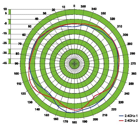
124 Appendix D - Antenna Pattern Antenna Pattern Antenna Pattern Orientation E-Plane H-Plane 2.4 GHz 119
125 Appendix E - Regulatory Information Regulatory Information Caution: Do not remove the plug and connect it to a power outlet by itself; always attach the plug to the power adapter first before connecting it to a power outlet. Federal Communication Commission Interference Statement: This equipment has been tested and found to comply with the limits for a Class B digital device, pursuant to Part 15 of the FCC Rules. These limits are designed to provide reasonable protection against harmful interference in a residential installation. This equipment generates, uses and can radiate radio frequency energy and, if not installed and used in accordance with the instructions, may cause harmful interference to radio communications. However, there is no guarantee that interference will not occur in a particular installation. If this equipment does cause harmful interference to radio or television reception, which can be determined by turning the equipment off and on, the user is encouraged to try to correct the interference by one of the following measures: Reorient or relocate the receiving antenna. Increase the separation between the equipment and receiver. Connect the equipment into an outlet on a circuit different from that to which the receiver is connected. Consult the dealer or an experienced radio/tv technician for help. Non-modifications Statement: Any changes or modifications not expressly approved by the party responsible for compliance could void the user s authority to operate this equipment. Caution: This device complies with Part 15 of the FCC Rules. Operation is subject to the following two conditions: (1) This device may not cause harmful interference, and (2) this device must accept any interference received, including interference that may cause undesired operation. For product available in the USA/Canada market, only channel 1~11 can be operated. Selection of other channels is not possible. This device and its antenna(s) must not be co-located or operating in conjunction with any other antenna or transmitter except in accordance with FCC multi-transmitter product procedures. 120
126 Appendix E - Regulatory Information Note: The country code selection is for non-us model only and is not available to all US model. Per FCC regulation, all Wi-Fi product marketed in US must fixed to US operation channels only. IMPORTANT NOTE: FCC Radiation Exposure Statement: This equipment complies with FCC radiation exposure limits set forth for an uncontrolled environment. This equipment should be installed and operated with minimum distance 20 cm between the radiator and your body. 121
127 Appendix E - Regulatory Information Industry Canada Statement: This device complies with Industry Canada licence-exempt RSS standard(s). Operation is subject to the following two conditions: (1) this device may not cause interference, and (2) this device must accept any interference, including interference that may cause undesired operation of the device. Le présent appareil est conforme aux CNR d'industrie Canada applicables aux appareils radio exempts de licence. L'exploitation est autorisée aux deux conditions suivantes : (1) l'appareil ne doit pas produire de brouillage, et (2) l'utilisateur de l'appareil doit accepter tout brouillage radioélectrique subi, même si le brouillage est susceptible d'en compromettre le fonctionnement. Radiation Exposure Statement This equipment complies with IC radiation exposure limits set forth for an uncontrolled environment. This equipment should be installed and operated with minimum distance 20 cm between the radiator & your body. Déclaration d'exposition aux radiations Cet équipement est conforme aux limites d'exposition aux rayonnements IC établies pour un environnement non contrôlé. Cet équipement doit être installé et utilisé avec un minimum de 20 cm de distance entre la source de rayonnement et votre corps. 122
128 Appendix E - Regulatory Information European Union: This device complies with the essential requirements of the R&TTE Directive 1999/5/EC. For more information, please refer to the Declaration of Conformity. Notice of Wireless Radio LAN Usage in The European Community: At the time of writing this addendum, some countries such as Italy, Greece, Portugal and Spain have not allowed operation of radio devices in the 5 Ghz bands, although operation of 2.4 Ghz radio devices are allowed. Please check with your local authority to confirm. This device is restricted to indoor use when operated in the European Community using channels in the GHz band to reduce the potential for interference. This device is a 2.4 GHz wideband transmission system (transceiver), intended for use in all EU member states and EFTA countries, except in France where restrictive use applies. This device may not be used for setting up outdoor radio links in France and in some areas the RF output power may be limited to 10 mw EIR P in the frequency range of MHz. For detailed information the end-user should contact the national spectrum authority in France. This equipment may be operated in AL, AD, BE, BG, DK, DE, FI, FR, GR, GW, IS, IT, HR, LI, LU, MT, MK, MD, MC, NL, NO, AT, OL, PT, RO, SM, SE, RS, SK, ES, CI, HU, CY Usage Notes: To remain in conformance with European National spectrum usage regulations, frequency and channel limitations will be applied on the products according to the country where the equipment will be deployed. This device is restricted from functioning in Ad-hoc mode while operating in 5 Ghz. Ad-hoc mode is direct peer-to-peer communication between two client devices without an Access Point. Access points will support DFS (Dynamic Frequency Selection) and TPC (Transmit Power Control) functionality as required when operating in 5 Ghz within the EU. 123
129 Appendix E - Regulatory Information 2.4 GHz Wireless Frequency and Channel Operation in EEC Countries: Region Frequency Band Max output power (EIRP) Metropolitan MHz 100 mw Guadeloupe, Martinique, St Pierre et Miquelon, Mayotte MHz 100 mw indoor, 10 mw outdoor Reunion et Guyane MHz 100 mw Rest of EU community MHz 100 mw R&TTE 1999/5/EC WLAN GHz IEEE b/g/n Spectrum Regulation MHz, Europa (ETSI) max. EIRP Innenbereich max. EIRP Außenbereich Europa MHz 100 mw 100 mw Frankreich MHz 100 mw 100 mw MHz 100 mw 10 mw 124
130 Appendix E - Regulatory Information European Community Declaration of Conformity: Česky [Czech] Dansk [Danish] Deutsch [German] Eesti [Estonian] English Español [Spanish] Ελληνική [Greek] Français [French] Italiano [Italian] Latviski [Latvian] Lietuvių [Lithuanian] Nederlands [Dutch] D-Link tímto prohlašuje, že tento DAP-3320 je ve shodě se základními požadavky a dalšími příslušnými ustanoveními směrnice 1999/5/ES. Undertegnede D-Link erklærer herved, at følgende udstyr DAP-3320 overholder de væsentlige krav og øvrige relevante krav i direktiv 1999/5/EF. Hiermit erklärt D-Link, dass sich das Gerät DAP-3320 in Übereinstimmung mit den grundlegenden Anforderungen und den übrigen einschlägigen Bestimmungen der Richtlinie 1999/5/EG befindet. Käesolevaga kinnitab D-Link seadme DAP-3320vastavust direktiivi 1999/5/EÜ põhinõuetele ja nimetatud direktiivist tulenevatele teistele asjakohastele sätetele. Hereby, D-Link, declares that this DAP-3320 is in compliance with the essential requirements and other relevant provisions of Directive 1999/5/EC. Por medio de la presente D-Link declara que el DAP-3320 cumple con los requisitos esenciales y cualesquiera otras disposiciones aplicables o exigibles de la Directiva 1999/5/CE. ΜΕ ΤΗΝ ΠΑΡΟΥΣΑ D-Link ΔΗΛΩΝΕΙ ΟΤΙ DAP-3320 ΣΥΜΜΟΡΦΩΝΕΤΑΙ ΠΡΟΣ ΤΙΣ ΟΥΣΙΩΔΕΙΣ ΑΠΑΙΤΗΣΕΙΣ ΚΑΙ ΤΙΣ ΛΟΙΠΕΣ ΣΧΕΤΙΚΕΣ ΔΙΑΤΑΞΕΙΣ ΤΗΣ ΟΔΗΓΙΑΣ 1999/5/ΕΚ. Par la présente D-Link déclare que l'appareil DAP-3320 est conforme aux exigences essentielles et aux autres dispositions pertinentes de la directive 1999/5/CE. Con la presente D-Link dichiara che questo DAP-3320 è conforme ai requisiti essenziali ed alle altre disposizioni pertinenti stabilite dalla direttiva 1999/5/CE. Ar šo D-Link deklarē, ka DAP-3320 atbilst Direktīvas 1999/5/EK būtiskajām prasībām un citiem ar to saistītajiem noteikumiem. Šiuo D-Link deklaruoja, kad šis DAP-3320 atitinka esminius reikalavimus ir kitas 1999/5/EB Direktyvos nuostatas. Hierbij verklaart D-Link dat het toestel DAP-3320 in overeenstemming is met de essentiële eisen en de andere relevante bepalingen van richtlijn 1999/5/EG. 125
![Appendix E - Regulatory Information Malti [Maltese] Magyar [Hungarian] Polski [Polish] Português [Portuguese] Slovensko [Slovenian] Slovensky [Slovak] Suomi [Finnish] Warning Statement: The power](/docs-images/74/70206435/images/131-0.jpg "outlet should be near the device and easily accessible.")
131 Appendix E - Regulatory Information Malti [Maltese] Magyar [Hungarian] Polski [Polish] Português [Portuguese] Slovensko [Slovenian] Slovensky [Slovak] Suomi [Finnish] Warning Statement: The power outlet should be near the device and easily accessible. Hawnhekk, D-Link, jiddikjara li dan DAP-3320 jikkonforma mal-ħtiġijiet essenzjali u ma provvedimenti oħrajn relevanti li hemm fid-dirrettiva 1999/5/EC. Alulírott, D-Link nyilatkozom, hogy a DAP-3320 megfelel a vonatkozó alapvetõ követelményeknek és az 1999/5/EC irányelv egyéb elõírásainak. Niniejszym D-Link oświadcza, że DAP-3320 jest zgodny z zasadniczymi wymogami oraz pozostałymi stosownymi postanowieniami Dyrektywy 1999/5/EC. D-Link declara que este DAP-3320 está conforme com os requisitos essenciais e outras disposições da Directiva 1999/5/CE. D-Link izjavlja, da je ta DAP-3320 v skladu z bistvenimi zahtevami in ostalimi relevantnimi določili direktive 1999/5/ES. D-Link týmto vyhlasuje, že DAP-3320 spĺňa základné požiadavky a všetky príslušné ustanovenia Smernice 1999/5/ES. D-Link vakuuttaa täten että DAP-3320 tyyppinen laite on direktiivin 1999/5/EY oleellisten vaatimusten ja sitä koskevien direktiivin muiden ehtojen mukainen. 126
132 Appendix E - Regulatory Information Safety Instructions Please adhere to the following safety guidelines to help ensure your own personal safety and protect your system from potential damage. Any acts taken that are inconsistent with ordinary use of the product, including improper testing, etc., and those not expressly approved by D-Link may result in the loss of product warranty. Unless expressly approved by an authorized representative of D-Link in writing, you may not and may not permit others to: Disassemble or reverse engineer the device or attempt to derive source code (underlying ideas, algorithms, or structure) from the device or from any other information provided by D-Link, except to the extent that this restriction is expressly prohibited by local law. Modify or alter the device. Remove from the device any product identification or other notices, including copyright notices and patent markings, if any. To reduce the risk of bodily injury, electrical shock, fire, and damage to the device and other equipment, observe the following precautions: Power Sources Observe and follow service markings. Do not push any objects into the openings of your device unless consistent with the authorized operation of the device. Doing so can cause a fire or an electrical shock by shorting out interior components. The powering of this device must adhere to the power specifications indicated for this product. Do not overload wall outlets and/or extension cords as this will increase the risk of fire or electrical shock. Do not rest anything on the power cord or on the device (unless the device is made and expressly approved as suitable for stacking). Position system cables and power cables carefully; route cables so that they cannot be stepped on or tripped over. Be sure that nothing rests on any cables. Operate the device only from the type of external power source indicated on the electrical ratings label. To help avoid damaging your device, be sure the voltage selection switch (if provided) on the power supply is set to match the power available at your location. Also be sure that attached devices are electrically rated to operate with the power available in your location. Use only approved power cable(s). If you have not been provided a power cable for your device or for any AC -powered option intended for your device, purchase a power cable that is approved for use in your country and is suitable for use with your device. The power cable must be rated for the device and for the voltage and current marked on the device's electrical ratings label. The voltage and current rating of the cable should be greater than the ratings marked on the device. 127
133 Appendix E - Regulatory Information To help prevent an electrical shock, plug the device and peripheral power cables into properly grounded electrical outlets. These cables are equipped with three-prong plugs to help ensure proper grounding. Do not use adapter plugs or remove the grounding prong from a cable. If you must use an extension cable, use a 3-wire cable with properly grounded plugs. Observe extension cable and power strip ratings. Ensure that the total ampere rating of all products plugged into the extension cable or power strip does not exceed 80 percent of the ampere ratings limit for the extension cable or power strip. To help protect your device from sudden, transient increases and decreases in electrical power, use a surge suppressor, line conditioner, or uninterruptible power supply (UPS). Do not modify power cables or plugs. Consult a licensed electrician or your power company for site modifications. Always follow your local/national wiring rules. When connecting or disconnecting power to hot-pluggable power supplies, if offered with your device, observe the following guidelines. Install the power supply before connecting the power cable to the power supply. Unplug the power cable before removing the power supply. If the system has multiple sources of power, disconnect power from the device by unplugging all power cables from the power supplies. Servicing/Disassembling Do not service any product except as expressly set forth in your system documentation. Opening or removing covers that are marked with the triangular symbol with a lightning bolt may expose you to an electrical shock. Only a trained service technician should service components inside these compartments. To reduce the risk of electrical shock, never disassemble this device. None of its internal parts are user-replaceable; therefore, there is no reason to access the interior. Do not spill food or liquids on your system components, and never operate the device in a wet environment. If the device gets wet, see the appropriate section in your troubleshooting guide or contact your trained service provider. Use the device only with approved equipment. Move products with care; ensure that all casters and/or stabilizers are firmly connected to the system. Avoid sudden stops and uneven surfaces. Environment Do not use this device near water (e.g. near a bathtub, sink, laundry tub, fish tank, in a wet basement or near a swimming pool). Do not use this device in areas with high humidity. 128
134 Appendix E - Regulatory Information This device must not be subjected to water or condensation. Keep your device away from radiators and heat sources. Also, do not block cooling vents. Cleaning Always unplug the power before cleaning this device. Do not use liquid or aerosol cleaners of any kind. Use only compressed air that is recommended for electronic devices. Use a dry cloth for cleaning. Protecting Against Electrostatic Discharge Static electricity can harm delicate components inside your system. To prevent static damage, discharge static electricity from your body before you touch any of the electronic components, such as the microprocessor. You can do so by periodically touching an unpainted metal surface on the chassis. You can also take the following steps to help prevent damage from electrostatic discharge (ESD): 1. When unpacking a static-sensitive component from its shipping carton, do not remove the component from the antistatic packing material until you are ready to install the component in your system. Just before unwrapping the antistatic packaging, be sure to discharge static electricity from your body. 2. When transporting a sensitive component, first place it in an antistatic container or packaging. 3. Handle all sensitive components in a static-safe area. If possible, use antistatic floor pads, workbench pads, and an antistatic grounding strap. Environmental This product may contain a battery. Recycle or dispose of batteries in accordance with the battery manufacturer's instructions and local/national disposal and recycling regulations. For more information, please refer to the warranty guide. 129
135 Appendix E - Regulatory Information Disposing of and Recycling Your Product ENGLISH This symbol on the product or packaging means that according to local laws and regulations this product should be not be disposed of in the household waste but sent for recycling. Please take it to a collection point designated by your local authorities once it has reached the end of its life, some will accept products for free. By recycling the product and its packaging in this manner you help to conserve the environment and protect human health. D-Link and the Environment At D-Link, we understand and are committed to reducing any impact our operations and products may have on the environment. To minimise this impact D-Link designs and builds its products to be as environmentally friendly as possible, by using recyclable, low toxic materials in both products and packaging. D-Link recommends that you always switch off or unplug your D-Link products when they are not in use. By doing so you will help to save energy and reduce CO2 emissions. To learn more about our environmentally responsible products and packaging please visit DEUTSCH DE Dieses Symbol auf dem Produkt oder der Verpackung weist darauf hin, dass dieses Produkt gemäß bestehender örtlicher Gesetze und Vorschriften nicht über den normalen Hausmüll entsorgt werden sollte, sondern einer Wiederverwertung zuzuführen ist. Bringen Sie es bitte zu einer von Ihrer Kommunalbehörde entsprechend amtlich ausgewiesenen Sammelstelle, sobald das Produkt das Ende seiner Nutzungsdauer erreicht hat. Für die Annahme solcher Produkte erheben einige dieser Stellen keine Gebühren. Durch ein auf diese Weise durchgeführtes Recycling des Produkts und seiner Verpackung helfen Sie, die Umwelt zu schonen und die menschliche Gesundheit zu schützen. D-Link und die Umwelt D-Link ist sich den möglichen Auswirkungen seiner Geschäftstätigkeiten und seiner Produkte auf die Umwelt bewusst und fühlt sich verpflichtet, diese entsprechend zu mindern. Zu diesem Zweck entwickelt und stellt D-Link seine Produkte mit dem Ziel größtmöglicher Umweltfreundlichkeit her und verwendet wiederverwertbare, schadstoffarme Materialien bei Produktherstellung und Verpackung. D-Link empfiehlt, Ihre Produkte von D-Link, wenn nicht in Gebrauch, immer auszuschalten oder vom Netz zu nehmen. Auf 130
136 Appendix E - Regulatory Information diese Weise helfen Sie, Energie zu sparen und CO2-Emissionen zu reduzieren. Wenn Sie mehr über unsere umweltgerechten Produkte und Verpackungen wissen möchten, finden Sie entsprechende Informationen im Internet unter FRANÇAIS FR Ce symbole apposé sur le produit ou son emballage signifie que, conformément aux lois et règlementations locales, ce produit ne doit pas être éliminé avec les déchets domestiques mais recyclé. Veuillez le rapporter à un point de collecte prévu à cet effet par les autorités locales; certains accepteront vos produits gratuitement. En recyclant le produit et son emballage de cette manière, vous aidez à préserver l environnement et à protéger la santé de l homme. D-Link et l environnement Chez D-Link, nous sommes conscients de l'impact de nos opérations et produits sur l'environnement et nous engageons à le réduire. Pour limiter cet impact, D-Link conçoit et fabrique ses produits de manière aussi écologique que possible, en utilisant des matériaux recyclables et faiblement toxiques, tant dans ses produits que ses emballages. D-Link recommande de toujours éteindre ou débrancher vos produits D-Link lorsque vous ne les utilisez pas. Vous réaliserez ainsi des économies d énergie et réduirez vos émissions de CO2. Pour en savoir plus sur les produits et emballages respectueux de l environnement, veuillez consulter le com ESPAÑOL ES Este símbolo en el producto o el embalaje significa que, de acuerdo con la legislación y la normativa local, este producto no se debe desechar en la basura doméstica sino que se debe reciclar. Llévelo a un punto de recogida designado por las autoridades locales una vez que ha llegado al fin de su vida útil; algunos de ellos aceptan recogerlos de forma gratuita. Al reciclar el producto y su embalaje de esta forma, contribuye a preservar el medio ambiente y a proteger la salud de los seres humanos. D-Link y el medio ambiente En D-Link, comprendemos y estamos comprometidos con la reducción del impacto que puedan tener nuestras actividades y nuestros productos en el medio ambiente. Para reducir este impacto, D-Link diseña y fabrica sus productos para que sean lo más ecológicos posible, utilizando materiales reciclables y de baja toxicidad tanto en los productos como en el embalaje. 131
137 Appendix E - Regulatory Information D-Link recomienda apagar o desenchufar los productos D-Link cuando no se estén utilizando. Al hacerlo, contribuirá a ahorrar energía y a reducir las emisiones de CO2. Para obtener más información acerca de nuestros productos y embalajes ecológicos, visite el sitio ITALIANO IT La presenza di questo simbolo sul prodotto o sulla confezione del prodotto indica che, in conformità alle leggi e alle normative locali, questo prodotto non deve essere smaltito nei rifiuti domestici, ma avviato al riciclo. Una volta terminato il ciclo di vita utile, portare il prodotto presso un punto di raccolta indicato dalle autorità locali. Alcuni questi punti di raccolta accettano gratuitamente i prodotti da riciclare. Scegliendo di riciclare il prodotto e il relativo imballaggio, si contribuirà a preservare l'ambiente e a salvaguardare la salute umana. D-Link e l'ambiente D-Link cerca da sempre di ridurre l'impatto ambientale dei propri stabilimenti e dei propri prodotti. Allo scopo di ridurre al minimo tale impatto, D-Link progetta e realizza i propri prodotti in modo che rispettino il più possibile l'ambiente, utilizzando materiali riciclabili a basso tasso di tossicità sia per i prodotti che per gli imballaggi. D-Link raccomanda di spegnere sempre i prodotti D-Link o di scollegarne la spina quando non vengono utilizzati. In questo modo si contribuirà a risparmiare energia e a ridurre le emissioni di anidride carbonica. Per ulteriori informazioni sui prodotti e sugli imballaggi D-Link a ridotto impatto ambientale, visitate il sito all'indirizzo www. dlinkgreen.com NEDERLANDS NL Dit symbool op het product of de verpakking betekent dat dit product volgens de plaatselijke wetgeving niet mag worden weggegooid met het huishoudelijk afval, maar voor recyclage moeten worden ingeleverd. Zodra het product het einde van de levensduur heeft bereikt, dient u het naar een inzamelpunt te brengen dat hiertoe werd aangeduid door uw plaatselijke autoriteiten, sommige autoriteiten accepteren producten zonder dat u hiervoor dient te betalen. Door het product en de verpakking op deze manier te recyclen helpt u het milieu en de gezondheid van de mens te beschermen. 132
138 Appendix E - Regulatory Information D-Link en het milieu Bij D-Link spannen we ons in om de impact van onze handelingen en producten op het milieu te beperken. Om deze impact te beperken, ontwerpt en bouwt D-Link zijn producten zo milieuvriendelijk mogelijk, door het gebruik van recycleerbare producten met lage toxiciteit in product en verpakking. D-Link raadt aan om steeds uw D-Link producten uit te schakelen of uit de stekker te halen wanneer u ze niet gebruikt. Door dit te doen bespaart u energie en beperkt u de CO2-emissies. Breng een bezoek aan voor meer informatie over onze milieuverantwoorde producten en verpakkingen POLSKI PL Ten symbol umieszczony na produkcie lub opakowaniu oznacza, że zgodnie z miejscowym prawem i lokalnymi przepisami niniejszego produktu nie wolno wyrzucać jak odpady czy śmieci z gospodarstwa domowego, lecz należy go poddać procesowi recyklingu. Po zakończeniu użytkowania produktu, niektóre odpowiednie do tego celu podmioty przyjmą takie produkty nieodpłatnie, dlatego prosimy dostarczyć go do punktu zbiórki wskazanego przez lokalne władze. Poprzez proces recyklingu i dzięki takiemu postępowaniu z produktem oraz jego opakowaniem, pomogą Państwo chronić środowisko naturalne i dbać o ludzkie zdrowie. D-Link i środowisko W D-Link podchodzimy w sposób świadomy do ochrony otoczenia oraz jesteśmy zaangażowani w zmniejszanie wpływu naszych działań i produktów na środowisko naturalne. W celu zminimalizowania takiego wpływu firma D-Link konstruuje i wytwarza swoje produkty w taki sposób, aby były one jak najbardziej przyjazne środowisku, stosując do tych celów materiały nadające się do powtórnego wykorzystania, charakteryzujące się małą toksycznością zarówno w przypadku samych produktów jak i opakowań. Firma D-Link zaleca, aby Państwo zawsze prawidłowo wyłączali z użytku swoje produkty D-Link, gdy nie są one wykorzystywane. Postępując w ten sposób pozwalają Państwo oszczędzać energię i zmniejszać emisje CO2. "Aby dowiedzieć się więcej na temat produktów i opakowań mających wpływ na środowisko prosimy zapoznać się ze stroną Internetową 133
139 Appendix E - Regulatory Information ČESKY CZ Tento symbol na výrobku nebo jeho obalu znamená, že podle místně platných předpisů se výrobek nesmí vyhazovat do komunálního odpadu, ale odeslat k recyklaci. Až výrobek doslouží, odneste jej prosím na sběrné místo určené místními úřady k tomuto účelu. Některá sběrná místa přijímají výrobky zdarma. Recyklací výrobku i obalu pomáháte chránit životní prostředí i lidské zdraví. D-Link a životní prostředí "Ve společnosti D-Link jsme si vědomi vlivu našich provozů a výrobků na životní prostředí a snažíme se o minimalizaci těchto vlivů. Proto své výrobky navrhujeme a vyrábíme tak, aby byly co nejekologičtější, a ve výrobcích i obalech používáme recyklovatelné a nízkotoxické materiály." "Společnost D-Link doporučuje, abyste své výrobky značky D-Link vypnuli nebo vytáhli ze zásuvky vždy, když je nepoužíváte. Pomůžete tak šetřit energii a snížit emise CO2." Více informací o našich ekologických výrobcích a obalech najdete na adrese MAGYAR HU Ez a szimbólum a terméken vagy a csomagoláson azt jelenti, hogy a helyi törvényeknek és szabályoknak megfelelően ez a termék nem semmisíthető meg a háztartási hulladékkal együtt, hanem újrahasznosításra kell küldeni. Kérjük, hogy a termék élettartamának elteltét követően vigye azt a helyi hatóság által kijelölt gyűjtőhelyre. A termékek egyes helyeken ingyen elhelyezhetők. A termék és a csomagolás újrahasznosításával segíti védeni a környezetet és az emberek egészségét. A D-Link és a környezet A D-Linknél megértjük és elkötelezettek vagyunk a műveleteink és termékeink környezetre gyakorolt hatásainak csökkentésére. Az ezen hatás csökkentése érdekében a D-Link a lehető leginkább környezetbarát termékeket tervez és gyárt azáltal, hogy újrahasznosítható, alacsony károsanyag-tartalmú termékeket gyárt és csomagolásokat alkalmaz. A D-Link azt javasolja, hogy mindig kapcsolja ki vagy húzza ki a D-Link termékeket a tápforrásból, ha nem használja azokat. Ezzel segít az energia megtakarításában és a széndioxid kibocsátásának csökkentésében. Környezetbarát termékeinkről és csomagolásainkról további információkat a weboldalon tudhat meg. 134
140 Appendix E - Regulatory Information NORSK NO Dette symbolet på produktet eller forpakningen betyr at dette produktet ifølge lokale lover og forskrifter ikke skal kastes sammen med husholdningsavfall, men leveres inn til gjenvinning. Vennligst ta det til et innsamlingssted anvist av lokale myndigheter når det er kommet til slutten av levetiden. Noen steder aksepteres produkter uten avgift. Ved på denne måten å gjenvinne produktet og forpakningen hjelper du å verne miljøet og beskytte folks helse. D-Link og miljøet Hos D-Link forstår vi oss på og er forpliktet til å minske innvirkningen som vår drift og våre produkter kan ha på miljøet. For å minimalisere denne innvirkningen designer og lager D-Link produkter som er så miljøvennlig som mulig, ved å bruke resirkulerbare, lav-toksiske materialer både i produktene og forpakningen. D-Link anbefaler at du alltid slår av eller frakobler D-Link-produkter når de ikke er i bruk. Ved å gjøre dette hjelper du å spare energi og å redusere CO2-utslipp. "For mer informasjon angående våre miljøansvarlige produkter og forpakninger kan du gå til DANSK DK Dette symbol på produktet eller emballagen betyder, at dette produkt i henhold til lokale love og regler ikke må bortskaffes som husholdningsaffald, mens skal sendes til genbrug. Indlever produktet til et indsamlingssted som angivet af de lokale myndigheder, når det er nået til slutningen af dets levetid. I nogle tilfælde vil produktet blive modtaget gratis. Ved at indlevere produktet og dets emballage til genbrug på denne måde bidrager du til at beskytte miljøet og den menneskelige sundhed. D-Link og miljøet Hos D-Link forstår vi og bestræber os på at reducere enhver indvirkning, som vores aktiviteter og produkter kan have på miljøet. For at minimere denne indvirkning designer og producerer D-Link sine produkter, så de er så miljøvenlige som muligt, ved at bruge genanvendelige materialer med lavt giftighedsniveau i både produkter og emballage. D-Link anbefaler, at du altid slukker eller frakobler dine D-Link-produkter, når de ikke er i brug. Ved at gøre det bidrager du til at spare energi og reducere CO2-udledningerne. Du kan finde flere oplysninger om vores miljømæssigt ansvarlige produkter og emballage på 135
141 Appendix E - Regulatory Information SUOMI FI Tämä symboli tuotteen pakkauksessa tarkoittaa, että paikallisten lakien ja säännösten mukaisesti tätä tuotetta ei pidä hävittää yleisen kotitalousjätteen seassa vaan se tulee toimittaa kierrätettäväksi. Kun tuote on elinkaarensa päässä, toimita se lähimpään viranomaisten hyväksymään kierrätyspisteeseen. Kierrättämällä käytetyn tuotteen ja sen pakkauksen autat tukemaan sekä ympäristön että ihmisten terveyttä ja hyvinvointia. D-Link ja ympäristö D-Link ymmärtää ympäristönsuojelun tärkeyden ja on sitoutunut vähentämään tuotteistaan ja niiden valmistuksesta ympäristölle mahdollisesti aiheutuvia haittavaikutuksia. Nämä negatiiviset vaikutukset minimoidakseen D-Link suunnittelee ja valmistaa tuotteensa mahdollisimman ympäristöystävällisiksi käyttämällä kierrätettäviä, alhaisia pitoisuuksia haitallisia aineita sisältäviä materiaaleja sekä tuotteissaan että niiden pakkauksissa. Suosittelemme, että irrotat D-Link-tuotteesi virtalähteestä tai sammutat ne aina, kun ne eivät ole käytössä. Toimimalla näin autat säästämään energiaa ja vähentämään hiilidioksiidipäästöjä. "Lue lisää ympäristöystävällisistä D-Link-tuotteista ja pakkauksistamme osoitteesta SVENSKA SE Den här symbolen på produkten eller förpackningen betyder att produkten enligt lokala lagar och föreskrifter inte skall kastas i hushållssoporna utan i stället återvinnas. Ta den vid slutet av dess livslängd till en av din lokala myndighet utsedd uppsamlingsplats, vissa accepterar produkter utan kostnad. Genom att på detta sätt återvinna produkten och förpackningen hjälper du till att bevara miljön och skydda människors hälsa. D-Link och miljön På D-Link förstår vi och är fast beslutna att minska den påverkan våra verksamheter och produkter kan ha på miljön. För att minska denna påverkan utformar och bygger D-Link sina produkter för att de ska vara så miljövänliga som möjligt, genom att använda återvinningsbara material med låg gifthalt i både produkter och förpackningar. D-Link rekommenderar att du alltid stänger av eller kopplar ur dina D-Link produkter när du inte använder dem. Genom att göra detta hjälper du till att spara energi och minska utsläpp av koldioxid. För mer information om våra miljöansvariga produkter och förpackningar 136

142 Appendix E - Regulatory Information PORTUGUÊS PT Este símbolo no produto ou embalagem significa que, de acordo com as leis e regulamentações locais, este produto não deverá ser eliminado juntamente com o lixo doméstico mas enviado para a reciclagem. Transporte-o para um ponto de recolha designado pelas suas autoridades locais quando este tiver atingido o fim da sua vida útil, alguns destes pontos aceitam produtos gratuitamente. Ao reciclar o produto e respectiva embalagem desta forma, ajuda a preservar o ambiente e protege a saúde humana. A D-Link e o ambiente Na D-Link compreendemos e comprometemo-nos com a redução do impacto que as nossas operações e produtos possam ter no ambiente. Para minimizar este impacto a D-Link concebe e constrói os seus produtos para que estes sejam o mais inofensivos para o ambiente possível, utilizando meteriais recicláveis e não tóxicos tanto nos produtos como nas embalagens. A D-Link recomenda que desligue os seus produtos D-Link quando estes não se encontrarem em utilização. Com esta acção ajudará a poupar energia e reduzir as emissões de CO2. Para saber mais sobre os nossos produtos e embalagens responsáveis a nível ambiental visite 137


143 Appendix F - Central WiFiManager FREE Central WiFiManager Software DOWNLOAD NOW DLINK.COM/WIFIDOWNLOAD With the easy-to-use web-based interface you can... Configure once and apply to multiple Access Points Install on Windows PC Access on any device using a web-browser, e.g. smartphone or notebook Utilise user authentication and access control Monitor your entire wireless network in real time 1 Access detailed reports Optimise your bandwidth FREE Central WiFiManager User Interface Supports multiple languages 1. see overleaf for selected product information. Connect to More 138


144 Appendix F - Central WiFiManager FREE Central WiFiManager Available on the following products 2 : DAP-2695 Wireless AC1750 Indoor Access Point Designed to support small to medium business or enterprise environments. Secure, manageable dual-band wireless LAN options. DAP-2660 Wireless AC1200 Indoor Ceiling Access Point Providing enhanced speeds of Wireless AC as well as dual-band connectivity to reduce interference, for a faster and more efficient network. DAP-2310 Wireless N Indoor Access Point Ideal for creating or expanding capacity of a wireless network; mainly used in high-traffic areas such as airports, coffee shops, sports venues, and university campus deployments. DAP-2360 Wireless N PoE Access Point For advanced indoor installations, this high-speed Access Point has integrated PoE support, allowing installation in areas where power outlets are not readily available. DAP-2690 Wireless N Simultaneous Dual-Band PoE Access Point Designed for indoor installation where power outlets are not readily available. Enables deployment of a highly manageable, robust and secure wireless network. DAP-2330 Wireless N PoE Access Point Ideal for wireless networks in high- traffic areas such as airports, coffee shops, shopping centres, sporting venues, hotels and campus deployments. PoE offers installation where power outlets are not available. 2. Visit dlink.com for selected Hardware & Software versions. Connect to More 139
Preface. Manual Revisions. Trademarks
 Preface D-Link reserves the right to revise this publication and to make changes in the content hereof without obligation to notify any person or organization of such revisions or changes. Manual Revisions
Document Created by Nick Schuster
 Document Created by Nick Schuster Table of Contents Product Overview... 4 Introduction... 4 Features... 5 Package Contents... 6 System Requirements... 6 Hardware Overview... 7 LEDs... 7 Connections...
Document Created by Nick Schuster
 Document Created by Nick Schuster Product Overview...4 Introduction... 4 Features... 5 Package Contents... 6 System Requirements... 6 Hardware Overview...7 LEDs... 7 Connections... 7 Basic Installation...8
Document Created by Nick Schuster
 Document Created by Nick Schuster Table of Contents Product Overview... 4 Introduction... 4 Features... 5 Package Contents... 6 System Requirements... 6 Hardware Overview... 7 LEDs... 7 Connections...
Wireless AC1200 Concurrent Dual Band PoE Access Point
 DAP-2660 Version 1.00 AirPremier Wireless AC1200 Concurrent Dual Band PoE Access Point Product Overview...5 Introduction... 5 Features... 6 Package Contents... 7 System Requirements... 7 Hardware Overview...8
Version /01/2013. User Manual. DAP-1665 Wireless AC1200 Dual Band Access Point DAP-1665
 Version 1.0 10/01/2013 User Manual DAP-1665 Wireless AC1200 Dual Band Access Point DAP-1665 Table of Contents Product Overview... 4 Package Contents... 4 System Requirements... 5 Introduction... 6 Features...
Table of Contents. Table of Contents
 Table of Contents Product Overview... 4 Package Contents...4 System Requirements...4 Introduction...5 Features and Benefits...6 Wireless Basics...7 Installation... 9 Installation Considerations...9 Four
Table of Contents. Product Overview...4 Package Contents...4 System Requirements... 4 Introduction...5 Features... 7
 Table of Contents Table of Contents Product Overview...4 Package Contents...4 System Requirements... 4 Introduction...5 Features... 7 Wireless Basics...8 Standards-Based Technology... 9 Wireless Installation
Version /25/2017. User Manual. DAP-1665 AC1200 Wi-Fi Range Extender/Access Point DAP-1665
 Version 2.00 01/25/2017 User Manual DAP-1665 AC1200 Wi-Fi Range Extender/Access Point DAP-1665 D-Link reserves the right to revise this publication and to make changes in the content hereof without obligation
Preface. Manual Revisions. Revision Date Description 1.0 March 3, 2009 DAP-3520 Revision A1 with firmware version Trademarks
 Preface D-Link reserves the right to revise this publication and to make changes in the content hereof without obligation to notify any person or organization of such revisions or changes. Manual Revisions
Table of Contents. Table of Contents
 Table of Contents Product Overview... 4 Package Contents... 4 System Requirements... 4 Introduction... 5 Features and Benefits... 6 Wireless Basics... 7 Four Operational Modes... 10 Getting Started...
Table of Contents. Product Overview...4 Package Contents...4 System Requirements...4 Introduction...5 Features...7
 Table of Contents Table of Contents Product Overview...4 Package Contents...4 System Requirements...4 Introduction...5 Features...7 Wireless Basics...8 Standards-Based Technology...9 Wireless Installation
Table of Contents. Getting Started...12 Connecting to a Power over Ethernet Network...13
 Table of Contents Product Overview...5 Package Contents...5 System Requirements...6 Introduction...7 Features...8 Wireless Basics...9 Standards-based Technology...10 Wireless Installation Considerations...11
Table of Contents. Table of Contents
 Table of Contents Product Overview... 4 Package Contents... 4 System Requirements... 5 Introduction... 6 Features... 8 Hardware Overview... 9 Connections... 9 LEDs...10 WPS LED/Button...11 Installation...12
Table of Contents. Table of Contents
 Table of Contents Table of Contents Product Overview...4 Package Contents... 4 System Requirements... 4 Features... 5 Hardware Overview... 6 Connections... 6 LEDs... 7 Wireless Installation Considerations...
Version /19/2013. User Manual. Wireless N Exterior Access Point DAP-3310
 Version 2.00 08/19/2013 User Manual Wireless N Exterior Access Point DAP-3310 Table of Contents Table of Contents Package Contents... 4 System Requirements... 5 Introduction... 6 Features... 8 Hardware
Version /03/2016. User Manual. Wireless N300 Access Point DAP-2020
 Version 1.0 11/03/2016 User Manual Wireless N300 Access Point DAP-2020 Table of Contents Package Contents... 4 System Requirements... 5 Introduction... 6 Features... 8 Hardware Overview... 9 Connections...
D-Link AirPlus G DWL-G700AP
 TM D-Link AirPlus G DWL-G700AP 2.4GHz Wireless Access Point Manual Building Networks for People Contents Package Contents...3 Introduction...4 Wireless Basics...6 Getting Started...8 Using the Configuration
802.11ac Wireless Access Point Model WAC104
 Point Model WAC104 User Manual October 2016 202-11698-01 350 E. Plumeria Drive San Jose, CA 95134 USA Support Thank you for purchasing this NETGEAR product. You can visit www.netgear.com/support to register
Table of Contents. Installation...9 Before you Begin...9 Wireless Installation Considerations AP/Bridge/Auto Mode...11
 Table of Contents Product Overview...4 Package Contents...4 System Requirements... 4 Introduction...5 Features... 6 Hardware Overview...7 Connections... 7 LEDs... 8 Installation...9 Before you Begin...9
Table of Contents Package Contents Introduction Features and Benefits Wireless Basics Four Operational Modes...
 User s Manual Table of Contents Table of Contents Table of Contents... 2 Package Contents... 3 Introduction... 4 Features and Benefits... 6 Wireless Basics... 7 Four Operational Modes... 10 Getting Started...
Version 1.00 May 02, User Manual. Wi-Fi AC600 Dual Band Mini Router DIR-516
 Version 1.00 May 02, 2014 User Manual Wi-Fi AC600 Dual Band Mini Router DIR-516 Preface D-Link reserves the right to revise this publication and to make changes in the content hereof without obligation
R2 BaseStation. Quick Installation Guide
 R2 BaseStation Quick Installation Guide V 1.0 March 2009 Page 1 Copyright Copyright 2009 all rights reserved. No part of this publication may be reproduced, adapted, stored in a retrieval system, translated
AC WiFi Business Access Point WAC510 User Manual
 AC WiFi Business Access Point WAC510 User Manual with NETGEAR Insight app for easy management December 2016 202-11686-01 350 E. Plumeria Drive San Jose, CA 95134 USA Support Thank you for purchasing this
Insight Managed Smart Cloud Wireless Access Point User Manual
 Insight Managed Smart Cloud Wireless Access Point User Manual Model WAC505 February 2018 202-11757-03 350 E. Plumeria Drive San Jose, CA 95134 USA Support Thank you for purchasing this NETGEAR product.
R1 Extender. Quick Installation Guide
 R1 Extender Quick Installation Guide V1.0 January 2009 Copyright Copyright 2008 all rights reserved. No part of this publication may be reproduced, adapted, stored in a retrieval system, translated into
Grandstream Networks, Inc. GWN76xx Wi-Fi Access Points Master/Slave Architecture Guide
 Grandstream Networks, Inc. GWN76xx Wi-Fi Access Points Master/Slave Architecture Guide Table of Contents INTRODUCTION... 4 DISCOVER AND PAIR GWN76XX ACCESS POINTS... 5 Discover GWN76xx... 5 Method 1: Discover
TRENDnet User s Guide. Cover Page
 Cover Page Contents Product Overview... 3 Package Contents... 3 Features... 3 Product Hardware Features... 4 Application Diagram... 6 Creating a Network... 6 Wireless Performance Considerations... 7 Getting
WL-5420AP. User s Guide
 WL-5420AP User s Guide Table of contents INTRODUCTION... 1 About the Operation Modes...2 LED Indicators...5 Solid...5 Ports on the Rear Panel...7 GETTING CONNECTED... 8 WPA AP -CONFIGURATION VIA WEB...
LevelOne. User Manual. WAP Mbps PoE Wireless AP V3.0.0
 LevelOne WAP-0005 108Mbps PoE Wireless AP User Manual V3.0.0 i TABLE OF CONTENTS CHAPTER 1 INTRODUCTION... 1 FIGURE 1: WIRELESS ACCESS POINT... 1 FEATURES OF YOUR WIRELESS ACCESS POINT... 1 Security Features...
R2 Extender. Quick Installation Guide
 R2 Extender Quick Installation Guide V 2.1.9 October 2009 Chapter 1 Introduction Page 1 Copyright Copyright 2009 all rights reserved. No part of this publication may be reproduced, adapted, stored in a
TRENDnet User s Guide. Cover Page
 Cover Page Contents Product Overview... 3 Package Contents... 3 Features... 3 Product Hardware Features... 4 Application Diagram... 5 Creating a Network... 6 Wireless Performance Considerations... 6 Getting
Version /04/2016. User Manual. Wireless AC750 Dual Band Router DIR-819
 Version 1.01 11/04/2016 User Manual Wireless AC750 Dual Band Router DIR-819 Preface D-Link reserves the right to revise this publication and to make changes in the content hereof without obligation to
LP-2396K Outdoor 2.4GHz Wireless AP/CPE/Bridge
 User Manual LP-2396K Outdoor 2.4GHz Wireless AP/CPE/Bridge 1 Table of Contents 1. Introduction... 3 1.1 Product Introduction... 4 1.2 Package Content... 5 1.3 Product Features... 6 1.4 Application... 6
Quick Installation Guide
 LWE120A LWE120AE codes codes codes LWE120A-KIT March 2009 LWE120AE-KIT codes codes codes Wireless Ethernet Extender Quick Installation Guide Customer Support Information Order toll-free in the U.S.: Call
Preface. Manual Revisions. Trademarks
 Preface D-Link reserves the right to revise this publication and to make changes in the content hereof without obligation to notify any person or organization of such revisions or changes. Manual Revisions
User Guide. 450Mbps/300Mbps Wireless N Access Point TL-WA901ND/TL-WA801ND REV
 User Guide 450Mbps/300Mbps Wireless N Access Point TL-WA901ND/TL-WA801ND REV4.0.0 1910011930 Contents About This Guide...1 Chapter 1. Get to Know About Your Access Point.................... 2 1. 1. Product
ENH900EXT N Dual Radio Concurrent AP. 2.4GHz/5GHz 900Mbps a/b/g/n Flexible Application
 ENH900EXT equips with two powerful independent RF interfaces which support 802.11a/n (3T3R) and 802.11b/g/n (3T3R). With certified IP-67 protection, it is designed to deliver high reliability under harsh
Version /13/2014. User Manual. mydlink Home Smart Plug DSP-W215
 Version 2.00 08/13/2014 User Manual mydlink Home Smart Plug DSP-W215 Preface D-Link reserves the right to revise this publication and to make changes in the content hereof without obligation to notify
Table of Contents. Installation... 9 Before you Begin... 9 Wireless Installation Considerations AP/Bridge/Auto Mode...11
 Table of Contents Product Overview... 4 Package Contents... 4 System Requirements... 4 Introduction... 5 Features... 6 Hardware Overview... 7 Connections... 7 LEDs... 8 Installation... 9 Before you Begin...
Insight Managed Smart Cloud Wireless Access Point User Manual
 Insight Managed Smart Cloud Wireless Access Point User Manual Model WAC510 February 2018 202-11840-03 350 E. Plumeria Drive San Jose, CA 95134 USA Support Thank you for purchasing this NETGEAR product.
ZAC / ZAC ZAC Wireless Access Point
 ZAC-1023-2-9 / ZAC-1023-5-13 ZAC Wireless Access Point Quick Installation Guide V1.2 Dec 2016 Copyright Copyright 2014 all rights reserved. No part of this publication may be reproduced, adapted, 1 stored
Insight Managed Smart Cloud Wireless Access Point User Manual
 Insight Managed Smart Cloud Wireless Access Point User Manual Model WAC510 September 2017 202-11840-01 350 E. Plumeria Drive San Jose, CA 95134 USA Support Thank you for purchasing this NETGEAR product.
Table of Contents Package Contents Introduction Features and Benefits Wireless Basics Three Operational Modes...
 Table of Contents Table of Contents Table of Contents... 2 Package Contents... 3 Introduction... 4 Features and Benefits... 6 Wireless Basics... 7 Three Operational Modes... 10 Getting Started... 11 Using
Wireless Access Point
 802.11g / 802.11b / WPA Wireless Access Point User's Guide TABLE OF CONTENTS CHAPTER 1 INTRODUCTION... 1 Features of your Wireless Access Point... 1 Package Contents... 4 Physical Details... 4 CHAPTER
Hardware overview. Package contents V-M200, documentation, three antennas, and power supply.
 The HP V-M200 is a Wi-Fi Alliance authorized Wi-Fi CERTIFIED 802.11a/b/g and 802.11n product. The Wi-Fi CERTIFIED Logo is a certification mark of the Wi-Fi Alliance. In HP V-M200 802.11n Access Point Quickstart
Version /19/2017. User Manual. Wireless AC1200 4G LTE Router DWR-961
 Version 0.01 09/19/2017 User Manual Wireless AC1200 4G LTE Router DWR-961 Section 1 - Product Overview Product Overview Package Contents DWR-961 Wireless AC1200 4G LTE Router Power Adapter 4G Antennas
Outdoor High Power Wireless N Access Point
 Outdoor High Power Wireless N Access Point Model WND930 User Manual December 2017 202-11483-02 350 East Plumeria Drive San Jose, CA 95134 USA Support Thank you for purchasing this NETGEAR product. You
Chapter 2 Installation and Configuration
 Chapter 2 Installation and Configuration This chapter describes how to set up your NETGEAR Wireless-N Access Point WN802T v2 for wireless connectivity to your LAN. This basic configuration will enable
Wireless AC1750 Wave 2 Dual-Band PoE Access Point
 Product Highlights Enjoy High-Performance Wireless Connectivity Harness the power of IEEE 802.11ac Wave 2 wireless and experience wireless speeds of up to 1750 Mbps 1, perfect for high-demand business
IEEE a/b/g/n Wireless LAN Access Point. AT-MWS AP series. Reference Manual
 IEEE 802.11a/b/g/n Wireless LAN Access Point AT-MWS AP series Reference Manual Table of Contents 1 Before You Begin 5 1.1 Considerations for Wireless Installation...6 Computer Settings...6 Hardware Installation...9
802.11ac 3x3 Dual Band High-Powered Wireless Access Point/Client Bridge
 Datasheet ECB1750 802.11ac 3x3 Dual Band High-Powered Wireless Access Point/Client Bridge The ECB1750 marks a new speed and performance breakthrough for users with 802.11ac laptops and other devices, who
802.11b/g Access Point WL-8000AP
 802.11b/g Access Point WL-8000AP User s Guide - FCC Certifications This equipment has been tested and found to comply with the limits for a Class B digital device, pursuant to Part 15 of the FCC Rules.
Table of Contents Package Contents Introduction Features and Benefits Wireless Basics Three Operational Modes...
 Table of Contents Table of Contents Table of Contents... 2 Package Contents... 3 Introduction... 4 Features and Benefits... 6 Wireless Basics... 7 Three Operational Modes... 10 Getting Started... 11 Using
A connected workforce is a more productive workforce
 A connected workforce is a more productive workforce D-Link wireless networking solutions enable business networks of all sizes to create highly mobile, highly productive work environments at a low total
Wireless Access Point
 802.11g / 802.11b / WPA Wireless Access Point User Guide TABLE OF CONTENTS CHAPTER 1 INTRODUCTION... 1 Features of your Wireless Access Point... 1 Package Contents... 4 Physical Details... 4 CHAPTER 2
Security SSID Selection: Broadcast SSID:
 69 Security SSID Selection: Broadcast SSID: WMM: Encryption: Select the SSID that the security settings will apply to. If Disabled, then the device will not be broadcasting the SSID. Therefore it will
OWL630 OUTDOOR ACCESS POINT
 OWL630 OUTDOOR ACCESS POINT Wireless INTRODUCTION The OWL630 is an enterprise-grade, concurrent dual-band 802.11ac outdoor access point, designed specifically to withstand harsh weather conditions in outdoor
ENH900 EXT ENH900 EXT. Wireless 11N Outdoor Dual Band Dual Concurrent AP /CB PRODUCT OVERVIEW
 Wireless 11N Outdoor Dual Band Dual Concurrent AP /CB 2.4GHz/5GH 900Mbps 802.11a/b/g/n PRODUCT OVERVIEW ENH900EXT equips with two powerful independent RF interfaces which support 802.11a/n (3T3R) and 802.11b/g/n
DWS-4000 Series DWL-3600AP DWL-6600AP
 Unified Wired & Wireless Access System Configuration Guide Product Model: Release 1.0 DWS-4000 Series DWL-8600AP DWL-6600AP DWL-3600AP Page 1 Table of Contents 1. Scenario 1 - Basic L2 Edge Setup: 1 Unified
Configuration Guide. Wireless Controller AC50/AC REV 1.0.0
 Configuration Guide Wireless Controller AC50/AC500 1910012001 REV 1.0.0 Content About This Guide... 1 1 Quick Start... 2 1.1 Determine the Network Topology... 2 1.1.1 Manage CAPs in the LAN...2 1.1.2 Manage
IEEE b/g/n Wireless Outdoor CPE. Quick Installation Guide
 IEEE 802.11b/g/n Wireless Outdoor CPE Quick Installation Guide F3.0.4 Sep 2011 Copyright Copyright 2011 all rights reserved. No part of this publication may be reproduced, adapted, stored in a retrieval
User Guide LAPN300. Wireless-N300. Access Point with POE. Model # LAPN300
 User Guide LAPN300 Wireless-N300 Access Point with POE Model # LAPN300 1 Contents Chapter 1 Quick Start Guide... 5 Mounting Guide... 6 Wall Installation... 6 Ceiling Installation... 6 Chapter 2 Access
Version /06/03. User Manual. AC1900 Wi-Fi Router DIR-879
 Version 1.01 2016/06/03 User Manual AC1900 Wi-Fi Router DIR-879 Preface D-Link reserves the right to revise this publication and to make changes in the content hereof without obligation to notify any person
TRENDnet User s Guide. Cover Page
 Cover Page Table of Contents Product Overview... 1 Package Contents... 1 Features... 1 Product Hardware Features... 2 Application Diagram... 3 Getting Started... 4 Steps to improve wireless connectivity...
User Guide. For TP-Link Auranet Access Points
 User Guide For TP-Link Auranet Access Points EAP110 / EAP115 / EAP225 / EAP245 / EAP320 / EAP330 / EAP115-Wall / EAP110-Outdoor 1910012276 REV 2.0.2 October 2017 CONTENTS About this User Guide... 1 Overview...
WAP3205 v2. User s Guide. Quick Start Guide. Wireless N300 Access Point. Default Login Details. Version 1.00 Edition 2, 12/2012
 WAP3205 v2 Wireless N300 Access Point Version 1.00 Edition 2, 12/2012 Quick Start Guide User s Guide Default Login Details LAN IP Address http://192.168.1.2 Password 1234 www.zyxel.com Copyright 2012 ZyXEL
LAPAC1200. AC1200 Dual Band Access Point. User's Guide
 LAPAC1200 AC1200 Dual Band Access Point User's Guide TABLE OF CONTENTS CHAPTER 1 QUICK START GUIDE... 1 Package Contents... 1 Physical Details... 1 Mounting Guide... 3 CHAPTER 2 ACCESS POINT SETUP...
Chapter 1 Introduction
 Copyright Statement is the registered trademark of Zonet Technology Inc. All the products and product names mentioned herein are the trademarks or registered trademarks of their respective holders. Copyright
EOC-2610 Long Range Wireless Access Point / Client Bridge
 EOC-2610 is a long range outdoor wireless that operates seamlessly in the frequency spectrum and provides high bandwidth up to 108Mbps with Super G. It features high transmitted output power and high receivable
11N Wall Mount Access Point / WDS AP / Universal Repeater. Features. Fully compatible with IEEE b/g/n devices
 EAP9550-KZ is a powerful and multi-functioned 11n Indoor Access Point and it can act three modes AP/WDS/Universal Repeater. Smoke detector appearance will minimize visibility. So this model can work properly
WH-9200AP a/b/g Dual Radio Wireless Base Station. User s Manual
 WH-9200AP 802.11a/b/g Dual Radio Wireless Base Station User s Manual Regulatory Information Federal Communication Commission Interference Statement This equipment has been tested and found to comply with
WRE2206. User s Guide. Quick Start Guide. Wireless N300 Range Extender. Default Details. Version 1.00 Edition 1, 01/2015
 WRE2206 Wireless N300 Range Extender Version 1.00 Edition 1, 01/2015 Quick Start Guide User s Guide Default Details Web Address http://zyxelsetup OR http://192.168.1.2 www.zyxel.com User Name admin Password
802.3at ac 3x3 Dual Band Ceiling Mount Access Point/WDS. can be used with EAP1750H. Key Features
 EAP1750H can be used with 802.3at capable switches or injectors 802.11ac 3x3 Dual Band Ceiling Mount Access Point/WDS The EAP1750H leverages the breakthrough speed and performance of 802.11ac for connecting
Preface. Manual Revisions. Trademarks
 DIR-815 Preface D-Link reserves the right to revise this publication and to make changes in the content hereof without obligation to notify any person or organization of such revisions or changes. Manual
ENH1750 EXT ENH1750 EXT
 Wireless 11AC Outdoor Dual Band Dual Concurrent AP /CB 2.4GHz/5GH 1750Mbps 802.11ac/b/g/n PRODUCT OVERVIEW ENH1750EXT equips with two powerful independent RF interfaces that support 802.11b/g/n (3T3R)
WRE6505 v2. User s Guide. Quick Start Guide. Wireless AC750 Range Extender. Default Login Details. Version 1.00 Edition 1, 10/2016
 WRE6505 v2 Wireless AC750 Range Extender Version 1.00 Edition 1, 10/2016 Quick Start Guide User s Guide Default Login Details Web Address http://zyxelsetup http://dhcp-assigned IP www.zyxel.comhttp://192.168.1.2
ZAC / ZAC ZAC Wireless Access Point
 ZAC-1023-2 / ZAC-1023-5 ZAC Wireless Access Point Quick Installation Guide V1.2 Dec 2016 1 Copyright Copyright 2014 all rights reserved. No part of this publication may be reproduced, adapted, stored in
Wireless 11n Smart Repeater AP (1T1R)
") (1T1R) 2014 Table of Contents 1. Introduction...3 1.1 Package contents... 3 1.2 Product Features... 3 1.3 Front Panel Description... 4 1.4 Rear Panel Description... 5 2. Installation...6 2.1 Hardware Installation...
(1T1R) 2014 Table of Contents 1. Introduction...3 1.1 Package contents... 3 1.2 Product Features... 3 1.3 Front Panel Description... 4 1.4 Rear Panel Description... 5 2. Installation...6 2.1 Hardware Installation...
Introduction. This product complies with the following European Union regulations: This product can be used safely in the countries listed below:
 WLX-2005 Introduction Thank you for purchasing the Sitecom WLX-2005 Wi-Fi Access Point N300. It complies with wireless 802.11b/g/n standards and can create a Wi-Fi network with data transmission rates
EAP9550 is a powerful and multi-functioned 11n Access Point
 11N Wall Mount Access Point / WDS AP / Universal Repeater 2.4GH/ 2Tx2R 11N 300Mbps AP/ WDS/Universal Repeater EAP9550 EAP9550 is a powerful and multi-functioned 11n Access Point and it can act three modes
Wireless-N Access Point with Power Over Ethernet
 Wireless-N Access Point with Power Over Ethernet User Guide Model: WAP4410N BUSINESS SERIES Linksys is a registered trademark or trademark of Cisco Systems, Inc. and/or its affiliates in the U.S. and certain
M a/b/g Outdoor Layer-2 MESH AP
 802.11a/b/g Outdoor Layer-2 MESH AP 2.4GHz / 5GHz 802.11 a/b/g MESH PRODUCT DESCRIPTION EnGenius Mesh AP is designed with IEEE802.11a/b/g standards and addressed on providing high performance mesh network.
Chapter 1 Introduction
 Copyright Statement is the registered trademark of Zonet Technology Inc. All the products and product names mentioned herein are the trademarks or registered trademarks of their respective holders. Copyright
Oct 2007 Version 1.01
 Oct 2007 Version 1.01 Table of Contents Introduction...4 System Requirement...4 Getting Started...4 Installing the Smart WLAN Manager...5 Discovering the Switch and AP...9 Understanding the Screen Layout...12
EnGenius EAP N Multi-Function AP/Repeater
 EnGenius EAP9550 11N Multi-Function AP/Repeater Table of Content 1. Introduction...4 1.1. Features and Benefits...4 1.2. Package Contents...5 1.3. System Requirement...5 2. Understanding the Hardware...6
PRODUCT OVERVIEW. Learn more about EnGenius Solutions at
 Dual Radio Multi-Function Repeater 2.4 GHz / 5 GHz 300Mbps 802.11a/b/g/n Multi Function PRODUCT OVERVIEW equips with two powerful independent RF interfaces which support 802.11a/b/g and 802.11b/g/n. With
CAP1750. User Manual / v1.1
 CAP1750 User Manual 12-2015 / v1.1 CONTENTS I. Product Information...2 I-1. Package Contents... 2 I-2. System Requirements... 3 I-3. Hardware Overview... 3 I-4. LED Status... 4 I-5. Reset... 4 I-6. Safety
WRE6606. User s Guide. Quick Start Guide. Dual-Band Wireless AC1300 Access Point. Default Login Details. Version 1.00 (ABDU.0) Edition 1, 10/2016
 Edition 1, 10/2016") WRE6606 Dual-Band Wireless AC1300 Access Point Version 1.00 (ABDU.0) Edition 1, 10/2016 Quick Start Guide User s Guide Default Login Details Web Address http://zyxelsetup http://dhcp-assigned IP www.zyxel.comhttp://192.168.1.2
WRE6606 Dual-Band Wireless AC1300 Access Point Version 1.00 (ABDU.0) Edition 1, 10/2016 Quick Start Guide User s Guide Default Login Details Web Address http://zyxelsetup http://dhcp-assigned IP www.zyxel.comhttp://192.168.1.2
Configuration Guide. Wireless Controller AC50/AC500
 Configuration Guide Wireless Controller AC50/AC500 1910012437 REV1.0.2 June 2018 Content About This Guide... 1 1 Quick Start... 2 1.1 Determine the Network Topology... 2 1.1.1 Manage CAPs in the LAN...2
Table of Contents. Chapter 1 Product Overview Features Package Contents LED Indicator and Panel Description...
 Copyright Statement is the registered trademark of Monoprice. All the products and product names mentioned herein are the trademarks or registered trademarks of their respective holders. Copyright of the
EnGenius EAP-9550 Indoor Access Point
 Product Name: Manufacturer: - Model Number: NET-EL-EAP9550 Please Note the has been discontinued, for alternative wireless equipment please check out Ubiquiti UniFi UAP LR EnGenius EAP9550 Indoor Access
EnGenius Quick Start Guide
 T he operates seamlessly in the 2.4 GHz frequency spectrum supporting the 802.11b (2.4GHz, 11Mbps) and the newer, faster 802.11g (2.4GHz, 54Mbpswireless standard. High output power and high sensitivity
802.11a/n Long Range Wireless Outdoor CB/A P
 ENS500 Key Features IEEE 802.11 a/n compliant Up to 300Mbps (5GHz) 24V Proprietary PoE support AP/CB/CR/WDS/Repeater Modes Multi-SSIDs with VLAN tagged VLAN tag pass-through via the WDS BR mode Web Configuration
Configuring the Wireless Parameters (CPE and WBS)
") Configuring the Wireless Parameters (CPE and WBS) CHAPTERS 1. Configure Basic Wireless Parameters 2. Configure Wireless Client Parameters 3. Configure Wireless AP Parameters 4. Configure Multi-SSID 5.
Configuring the Wireless Parameters (CPE and WBS) CHAPTERS 1. Configure Basic Wireless Parameters 2. Configure Wireless Client Parameters 3. Configure Wireless AP Parameters 4. Configure Multi-SSID 5.
Wi-Fi EOC Slave Quick Start Guide
 Wi-Fi EOC Slave Quick Start Guide Catalog 1. Hardware Setup... 3 1.1 Unpack Your EOC slave... 3 1.2 Hardware Features... 3 1.3 Position Your EOC Slave... 5 1.4 Cable Your EOC Slave... 5 2 Getting Start...
EOA3630 Outdoor 7 Multi-Function AP/CB
 The outdoor wireless device EOA3630 is a powerful, enhanced, enterprise scale product with 7 multi-functions. External N-type connector provides antenna extend. It features output power levels setting,
TRENDnet User s Guide. Cover Page
 Cover Page Table of Contents Product Overview... 1 Package Contents... 1 Features... 1 Product Hardware Features... 2 Application Diagram... 3 Getting Started... 4 Steps to improve wireless connectivity...
Preface. Manual Revisions. Revision Date Description 8.0 November 08, 2010 Updated for revision H1. Trademarks
 Preface D-Link reserves the right to revise this publication and to make changes in the content hereof without obligation to notify any person or organization of such revisions or changes. Manual Revisions
AC1200 Dual Band Wireless Controller Kit TEW-821DAP2KAC (v1.0r)
") AC1200 Dual Band Wireless Controller Kit TEW-821DAP2KAC (v1.0r) Centralized AP management Includes two dual band wireless AC1200 access points with PoE injectors Wireless controller with five gigabit ports
AC1200 Dual Band Wireless Controller Kit TEW-821DAP2KAC (v1.0r) Centralized AP management Includes two dual band wireless AC1200 access points with PoE injectors Wireless controller with five gigabit ports