> Avaya IP Telephony Deployment Technical Configuration Guide. Avaya IP Phones Avaya Ethernet Routing Switches Engineering
|
|
|
- Quentin Malone
- 6 years ago
- Views:
Transcription
1 Avaya IP Phones Avaya Ethernet Routing Switches Engineering > Avaya IP Telephony Deployment Technical Configuration Guide Avaya Data Solutions Document Date: October 2010 Document Number : NN Document Version: 7.0
2 Abstract The purpose of this TCG is to review the many options available on Nortel Ethernet and Ethernet Routing Switches for interoperability with Avaya s IP Phone sets. Revision Control No Date Version Revised by Remarks 1 07/12/ ESE Modification to section on page /28/ ESE Modifications 3 02/14/ ESE 4 8/4/ JVE 5 8/26/ JVE Added updates related to ADAC and EAPOL. Added ERS2500 and ERS4500 switches. Updates related to auto provisioning and software updates on various switches Updated based on all Avaya IP Phones and added features on various Avaya switches. Added AES (Avaya Energy Savings) 1
3 Table of Contents CONVENTIONS OVERVIEW AUTOMATIC PROVISIONING CONFIGURATION EXAMPLES REFERENCE DIAGRAMS Diagram 1 : Stackable Ethernet Routing Switch Diagram 2 : Ethernet Routing Switch AUTO CONFIGURATION WITH A STACKABLE ETHERNET ROUTING SWITCH USING DHCP BASE CONFIGURATION Stackable Switch Configuration Verify Operations AUTO CONFIGURATION WITH A STACKABLE ETHERNET ROUTING SWITCH USING DHCP AND LLDP-MED Stackable Ethernet Switch Configuration Verify Operations AUTO CONFIGURATION WITH AN ETHERNET ROUTING SWITCH 8300 USING DHCP ERS 8300 Configuration Verify Operations AUTO CONFIGURATION USING ADAC MAC DECTECTION USING A STACKABLE ETHERNET ROUTING SWITCH Stackable Ethernet Switch Configuration Verify configuration AUTO CONFIGURATION USING ADAC LLDP DECTECTION USING A STACKABLE ETHERNET ROUTING SWITCH Stackable Ethernet Switch Configuration Verify operations AUTO CONFIGURATION WITH A STACKABLE ETHERNET ROUTING SWITCH WITH EAP MHMA Stackable Switch Configuration Verify Operations RADIUS Server Configuration AUTO CONFIGURATION WITH A STACKABLE ETHERNET ROUTING SWITCH USING EAP WITH NEAP AND USER BASED POLICY Stackable Switch Configuration Verify Operations RADIUS Server Policy Setup AUTO CONFIGURATION WITH A STACKABLE ETHERNET ROUTING SWITCH USING EAP WITH NON- EAP-PHONE SUPPORT AND ADAC (LLDP DETECTION) Stackable Switch Configuration Verify Operations AVAYA IP PHONE DHCP AND PROVISIONING FILES DHCP Settings Provisioning Files AVAYA ENERGY SAVER (AES) Go to configuration mode Add SNTP Server Add Avaya Energy Saver configuration Verify operations
4 2.12 DHCP SERVER SETUP Windows 2003 DHCP Configuration AVAYA IP DESKPHONES SERIES IP DESKPHONES Feature Comparison Accessing the Configuration Menu (2001/2002/2004) Configuration Menu on Phase II IP Phone 2001, Phase II IP Phone 2002 and Phase II IP Phone Accessing the Configuration Menu (2007 IP Deskphone) Configuration Menu on the 2007 IP Deskphone SERIES IP DESKPHONES Feature Comparison Accessing the Configuration Menu Configuration Menu on the 1120E/1140E/1150E/1165E IP Deskphone SERIES IP DESKPHONE Feature Comparison Access the Configuration Menu Configuration Menu on IP Phone 12xx Series and IP Phone RESTORE TO FACTORY DEFAULTS (APPLIES TO 1100-SERIES, 1200-SERIES, AND 2007 IP DESKPHONES) SERIES IP DESKPHONES Feature Comparison SERIES IP DESKPHONES Feature Comparison AUTOMATIC PROVISIONING: PLUG AND PLAY IP TELEPHONY AUTO PROVISIONING ON AVAYA IP DESKPHONES (1100-SERIES, 1200-SERIES, 2000-SERIES) Provisioning Server Using TFTP/HTTP/HTTPS LLDP DHCP AUTO PROVISIONING ON AVAYA IP DESKPHONES (1600-SERIES, 9600-SERIES) LLDP DHCP Provisioning Server Using HTTP or HTTPS SNMP AUTO DETECTION AND AUTO CONFIGURATION (ADAC) OF AVAYA IP PHONES ADAC Operating Modes QoS Settings ADAC Configuration LINK LAYER DISCOVERY PROTOCOL (IEEE 802.1AB) Protocol Behavior Mandatory TLVs Optional TLVs Basic Management TLVs IEEE Organization Specific TLV TIA LLDP-MED Extensions LLDP Support on Avaya Switches LLDP Configuration on Avaya IP Phone Sets and Switches LLDP VLAN Name LLDP-MED (Media Endpoint Devices) Network Policy
5 AF POWER OVER ETHERNET IP DESKPHONE POWER REQUIREMENTS AVAYA POE SWITCHES CONFIGURING POE Stackable Ethernet Routing Switch Ethernet Routing Switch AVAYA ENERY SAVER QOS INTERFACE ROLES STACKABLE ETHERNET ROUTING SWITCH DEFAULT QOS OPERATIONS - ERS QOS MAPPING QUEUE SETS Ethernet Routing Switch Ethernet Routing Switch Ethernet Routing Switch Ethernet Routing Switch AUTOMATIC QOS Automatic QoS Edge Mode: Stackable Ethernet Routing Switch Automatic QoS Configuration Stackable Ethernet Routing Switch CONFIGURING QOS ON A AVAYA SWITCH FOR VOICE TRAFFIC Stackable Ethernet Routing Switch - Creating a new Interface Group of Trusted Stackable Ethernet Routing Switch - Assuming default role combination with class of untrusted Configure L2 QoS on a Ethernet Routing Switch ANTI-SPOOFING BEST PRACTICES EAPOL SUPPORT EAP OVERVIEW EAP SUPPORT ON AVAYA IP PHONE SETS EAP AND ADAC EAP SUPPORT ON AVAYA SWITCHES EAP FEATURE OVERVIEW AND CONFIGURATION ON AVAYA STACKABLE SWITCHES Single Host Single Authentication: SHSA Guest VLAN Multiple Host Multiple Authentication: MHMA MHMA Radius Assigned VLANs MHMA MultiVLAN MHMA Last Assigned RADIUS VLAN MHMA with Fail Open VLAN Enhanced MHMA Feature: Non-EAP-MAC (NEAP) Enhanced MHMA Feature: Non-EAP IP Phone client EAP/NEAP with VLAN Names Unicast EAP Request in MHMA User Based Policies (UBP) EAP CONFIGURATION USING EDM RADIUS SETUP RADIUS Setup for NEAP RADIUS Setup for Dynamic VLAN Assignment
6 10. APPENDIXES APPENDIX A: IP DESKPHONE INFO BLOCK (APPLIES TO THE 2001, 2002, 2004, 2007, 1110, 1120E, 1140E, 1150E, 165E, 1210, 1220, AND 1230 IP DESKPHONES) APPENDIX B: DHCP CONFIGURABLE PARAMETERS AVAYA 9600 SERIES H323 IP PHONES APPENDIX C: DHCP CONFIGURABLE PARAMETERS AVAYA 9600 SERIES SIP IP PHONES APPENDIX D: DHCP CONFIGURABLE PARAMETERS AVAYA 1600 SERIES H.323 IP DESKPHONES APPENDIX E: DHCP CONFIGURABLE PARAMETERS AVAYA 1600 SERIES SIP IP DESKPHONES APPENDIX F: 46XXSETTINGS.TXT CONFIGURATION FILE REFERENCE DOCUMENTATION
7 List of Figures Figure 1: Base setup - Stackable Ethernet Routing Switch Setup Figure 2: Base setup - Ethernet Routing Switch 8300 Setup Figure 3: IP Phone 2004 Access Configuration Menu Figure 4: IP Phone 2002 Access Configuration Menu Figure 5: IP Phone 2004 Power Cycle Phone Set Figure 6: IP Phone 2002 Power Cycle Phone Set Figure 7: IP Phone 2007 Phone Set Figure 8: 1100 Series IP Deskphone Setup Figure 9: 1200 Series IP Deskphone Setup Figure 10: IEEE LLDP frame format Figure 11: LLDPDU Frame Format Figure 12: Organizationally Specific TLV Format Figure 13: LLDP-MED TLV Format Figure 14: Organizational TLV SubType 3 TLV Frame Format Figure 15: LLDP-MED Network Policy TLV SubType 2 Frame Format Figure 16: PD and PSE 8-pin Modular Jack Pin s Figure 17: Redundant Power Supply 15 (RPS15) Figure 18: EAP Overview Figure 19: EAP Frame
8 List of Tables Table 1: Avaya IP Deskphones 2000 Series Table 2: Avaya IP Deskphones 1100 Series Table 3: Avaya IP Phone Sets 1200 series Table 4: Avaya IP Phone Sets 1600 series Table 5: Avaya IP Phone Sets 9600 series Table 6: DHCP Response Codes Table 7: ADAC Support on Avaya Switches Table 8: TLV Type Values Table 9: Organizational TLV Table 10: LLDP MED TLV Table 11: LLDP Support on Avaya Switches Table 12: PSE Pinout Alternative Table 13: 802.3af PD Power Classification Table 14: IP Deskphone Power Requirements Table 15: ERS 8300 Power over Ethernet Options Table 16: ERS 5600 Power over Ethernet Options Table 17: ERS 5500 Power over Ethernet Options Table 18: ERS 4500 Power over Ethernet Options Table 19: ERS 2500 Power over Ethernet Options Table 20: RPS 15 Configuration Options Table 21: Default QoS fields by class of interface IPv4 only Table 22: Avaya QoS Class Mappings Table 23: Ethernet Routing Switch 4500 ASIC Table 24: Ethernet Routing Switch 8300 Egress Queue Table 25: NT DSCP Mapping Values (Mixed) Table 26: NT DSCP Values (Pure) Table 27: Default QOS Behavior for the Ethernet Routing Switch Table 28: MITM Attacks Table 29: Anti-Spoofing support on Avaya Switches Table 30: EAP Support on Avaya IP Phones Table 31: EAP Support on Avaya Switches Table 32: NEAP Passwords
9 Conventions This section describes the text, image, and command conventions used in this document. Symbols Tip Highlights a configuration or technical tip. Note Highlights important information to the reader. Warning Highlights important information about an action that may result in equipment damage, configuration or data loss. Text Bold text indicates emphasis. Italic text in a Courier New font indicates text the user must enter or select in a menu item, button or command: ERS T# show running-config Output examples from Avayadevices are displayed in a Lucida Console font: ERS T# show running-config! Embedded ASCII Configuration Generator Script! Model = Ethernet Routing Switch ERS-Stackable! Software version = v enable configure terminal 8
10 1. Overview This TCG covers standalone Avaya IP Phone sets and how they can be deployed on various Avaya switches. It will cover features on Avaya switches related to VoIP with configuration examples. Overall, topics that will be covered include the following: Ethernet switch platforms that support PoE: Ethernet Routing Switch 5000: T-PWR, 5650TD-PWR, 5698TFD-PWR Ethernet Routing Switch 4500: 4526T-PWR, 4550T-PWR, 4524GT-PWR, 4526GTX- PWR, 4548GT-PWR Ethernet Routing Switch 2500: 2526T-PWR, 2550T-PWR Ethernet Routing Switch 8300 VoIP technologies: Auto configuration via DHCP for VoIP Phone sets Auto provisioning using tftp or http Avaya Energy Saver (AES) Authentication using EAPoL (802.1x) Auto Detection Auto Configuration (ADAC) Link Layer Discovery Protocol (LLDP) Power over Ethernet (PoE) Quality over Service (QoS) 9
11 2. Automatic Provisioning Configuration Examples This section will cover various configuration examples to allow for automatic or zero-touch provisioning of Avaya IP phones using Avaya data switches. The following chart summarizes each configuration example. Section Item QoS Description 2.2 Double DHCP Manually configured 1 Uses DHCP to get VLAN ID for voice VLAN from data DHCP scope 2.3 LLDP-MED Manually configured 1 Switch uses LLDP-MED Network Policy to provision voice VLAN 2.4 Double DHCP None Uses DHCP to get VLAN ID for voice VLAN from data DHCP scope using the ERS ADAC MAC Automatically applied Uses ADAC to automatically detect IP Detection 2.6 ADAC LLDP Detection to Voice VLAN Automatically applied to Voice VLAN 2 Phone using MAC address of IP Phone Switch uses ADAC to automically detect IP Phone using LLDP and uses LLDP- MED Network Policy to set VLAN ID and QoS settings for the IP Phone 2.7 EAP MHMA N/A Optional configuration to enable IP Phones as an EAP Supplicant using MD5 2.8 EAP NEAP N/A Optional configuration using the EAP NEAP feature on the switch allowing it to authenticate the IP Phone using its MAC address 2.9 EAP non-eapphone 2.10 DHCP and Provisioning files 2.11 Avaya Energy N/A N/A N/A Optional configuration using the EAP noneap-phone feature on the switch allowing it to authenticate the IP Phone using the IP phone DHCP signature without using RADIUS DHCP server settings and provisioning files for the IP Phones used in this example Optional configuration adding AES to the switch Saver 2.12 DHCP Server N/A Windows 2003 DHCP server settings 1 QoS can be added in a number of methods such as simply trusting all traffic, applying filters, or enabling Auto QoS (applies to Avaya 1100, 1200, or 2000 series only) 2 The LLDP-MED Network Policy can also set the QoS DSCP and p-bit priority values 10
 setup as a Layer 2 switch connected to an SMLT Cluster The SMLT Cluster requires that DHCP Relay be enabled")
12 2.1 Reference Diagrams Diagram 1 : Stackable Ethernet Routing Switch Figure 1: Base setup - Stackable Ethernet Routing Switch Setup The following are the details for the base configuration: ERS-Stackable is a stackable Ethernet Routing Switches (ERS 2500, 4500, or 5000 series) setup as a Layer 2 switch connected to an SMLT Cluster The SMLT Cluster requires that DHCP Relay be enabled with a DHCP Relay agent for both the voice and data VLANs Overall, we will configure the following o Create Voice VLAN 805 with port members 3 to 11, 23, and 24 o Create Data VLAN 1002 with port members 3 to 11, 23, and 24 o Create Management VLAN 201 with port members 23 and 24 o Configure access ports 3 to 11 to allow untagged Data VLAN 1002 and tagged Voice VLAN 805 o Configure core ports 23 and 24 using MLT 1 using VLAN tagging and with Spanning disabled o Use all the recommended SMLT best practises Details regarding various Avaya IP Phone DHCP and provisioning file parameters are listed in Appendix A 11

13 2.1.2 Diagram 2 : Ethernet Routing Switch 8300 Figure 2: Base setup - Ethernet Routing Switch 8300 Setup Overall, we will configure the following: Create Voice VLAN 220 with port members 1/1 to 1/25 Create Data VLAN 61 with port members 1/1 to 1/25 Create Trunk VLAN 83 with port member 5/5 Enable DHCP relay for VLAN 220 and 61 Enable Spanning Tree Fast-Start on ports 1/1 to 1/25 and disable STP on port 5/5 Configure all voice ports, 1/1 to 1/25, with POE priority of high Enable RIP on all VLANs By default, the ERS 8300 passes both the DSCP and p-bit values as-is. The p-bit value determines the QoS level. For this example, we will not configure QoS as we are using VLAN tagging for the Voice VLAN Details regarding various Avaya IP Phone DHCP and provisioning file parameters are listed in Appendix A 12
14 2.2 Auto Configuration with a Stackable Ethernet Routing Switch using DHCP Base Configuration The following configuration example covers setting up a network to support both voice and data with Avaya s stackable Ethernet Routing switches and IP Phone sets using DHCP to configure the IP Phone sets. Please note, it is still advisable to use a provisioning server to allow for full configuration of the IP phone sets. We will cover how to setup the edge switch for Layer 2 operations using the best practises when connecting to an SMLT cluster. This configuration example is in reference to diagram Stackable Switch Configuration Go to configuration mode. ERS-Stackable Step 1 - Enter configuration mode ERS-Stackable>enable ERS-Stackable#configure terminal Create VLAN s ERS-Stackable Step 1 Create VLAN s 201, 805, and 1002 ERS-Stackable(config)#vlan create 201 name mgmt type port ERS-Stackable(config)#vlan create 805 name voice type port ERS-Stackable(config)#vlan create 1002 name data type port ERS-Stackable Step 2 Enable VLAN tagging on all appropriate ports ERS-Stackable(config)#vlan port tagging tagall ERS-Stackable(config)#vlan port 3-11 tagging untagpvidonly ERS-Stackable Step 3 Set VLAN configuration control to automatic and add VLAN port members ERS-Stackable(config)# vlan configcontrol automatic ERS-Stackable(config)#vlan members add ERS-Stackable(config)#vlan members add ,23-24 ERS-Stackable(config)#vlan members add ,23-24 ERS-Stackable(config)#vlan port 3-11 pvid 1002 ERS-Stackable Step 4 Remove port members from the default VLAN ERS-Stackable(config)#vlan members remove ,
15 Add MLT ERS5698TFD-1 Step 1 Add MLT with trunk members ERS-Stackable(config)# mlt 1 enable member 23,24 learning disable Enable VLACP on trunk members using recommend values ERS-Stackable Step 1 Enable VLACP on uplink port member 23 and 24 using the recommended VLACP MAC and timeout values ERS-Stackable(config)#vlacp macaddress 01:80:c2:00:00:0f ERS-Stackable(config)#vlacp enable ERS-Stackable(config)#interface fastethernet 23,24 ERS-Stackable(config-if)#vlacp timeout short ERS-Stackable(config-if)#vlacp timeout-scale 5 ERS-Stackable(config-if)#vlacp enable ERS-Stackable(config-if)#exit Discard Untagged Frames on uplink ports to SMLT Cluster ERS-Stackable: Step 1 Enable Discard Untagged Frames ERS-Stackable(config)#vlan ports filter-untagged-frame enable 14
16 Configure Management IP address on switch An IP address can be added in one of two ways. If the switch is strictly used as a Layer 2 switch, then an IP address can be added via the Layer 2 method using the CLI command ip address <switch stack> <IP address> netmask <mask> default-gateway <default GW> Adding Management IP - Layer 2 ERS-Stackable Step 1 Set the IP address of the switch ERS-Stackable(config)#vlan mgmt 201 ERS-Stackable(config)# ip address switch netmask default-gateway Adding Management IP - Layer 3 ERS-Stackable Step 1 Set the IP address of the switch ERS-Stackable(config)#vlan mgmt 201 ERS-Stackable(config)#interface vlan 201 ERS-Stackable(config-if)#ip address netmask ERS-Stackable(config-if)#exit ERS-Stackable Step 1 Add the default route ERS-Stackable(config)#ip routing ERS-Stackable(config)#ip route Configure PoE levels If you wish, you can change the default PoE level of low to either high or critical. ERS-Stackable Step 1 Set PoE Power level high on all VoIP ports ERS-Stackable(config)#interface fastethernet 3-11 ERS-Stackable(config)# poe poe-priority high ERS-Stackable(config)#exit 15
17 QoS There are several options you can deploy to add QoS for the voice traffic. Assign QoS class of trusted to all ports easiest to implement, but, trust s all traffic which may not be a good idea Assign QoS class of trusted to all ports and adding a filter to remark the data traffic Set all access ports as untrusted (default setting), set uplink ports as trusted, and add a filter to remark the voice traffic to CoS level of Premium Enable Auto QoS only supported on limited Avaya products as listed below o CS1000, CS2100, BCM, and/or SRG call servers Enable ADAC automatically provides QoS only to the voice VAN For this example, we will simply trust all traffic by simply setting all ports as trusted ports. This is the easiest method for applying QoS. If you are using an Avaya Ethernet Routing Switch 5000 or Ethernet Routing Switch 4500 (release 5.4 or higher), you will need to define a queue set other than the default queue set which only uses two queues. At mimimum, it is recommended to use queue set 4 which will provide three weighted queues and one strict queue using the CLI command qos agent queue-set 4. Use the CLI command show qos queue-set to view the make up for each queue set. The ERS 2500 only supports one queue set, queue set 4, which supports one strict queue and three weighted-round-robin (WWR) queues. ERS-Stackable Step 1 Change from default queue set (queue set 2) to at least queue set 4 and reset the switch. Note, this only applies to the ERS 5000 or ERS 4500 ERS-Stackable(config)#qos agent queue-set 4 QoS queue setting isn't effective until after reset. ERS-Stackable Step 2 Create a new interface group with a class of trusted ERS-Stackable(config)#qos if-group name trusted class trusted ERS-Stackable(config)#qos if-assign port 1-24 name trusted ERS-Stackable Step 3 Traffic Profile Option. Configure either a traffic profile or ACL to remark the data VLAN with a QoS level of Standard depending on switch model. Assuming ERS-Stackable is an ERS 4500 or ERS 5000, it is recommend to use traffic profiles ERS-Stackable(config)#qos traffic-profile classifier name one vlan-min 1002 vlan-max 1002 ethertype 0x800 update-dscp 0 update-1p 0 ERS-Stackable(config)#qos traffic-profile set port 1-13 name one 16
18 ERS-Stackable Step 3 ACL Option. Configure either a traffic profile or ACL to remark the data VLAN with a QoS level of Standard depending on switch model. ACL s can be used on a ERS 2500, ERS 4500, or ERS 5000 where it is recommended to use traffic profiles over ACL s if supported on the switch ERS-Stackable(config)#qos l2-acl name one vlan-min 1002 vlan-max 1002 ethertype 0x800 update-dscp 0 update-1p 0 ERS-Stackable(config)#qos l2-acl name one ethertype 0x800 drop-action disable ERS-Stackable(config)#qos acl-assign port 1-13 acl-type l2 name one Spanning Tree Configuration ERS-Stackable Step 1 Enable STP Fast-Start and BPDU filtering on port 3 to 11 ERS-Stackable(config)#interface fastethernet all ERS-Stackable(config-if)#spanning-tree port 3-11 learning fast ERS-Stackable(config-if)#spanning-tree port 3-11 bpdu-filtering timeout 0 ERS-Stackable(config-if)#spanning-tree port 3-11 bpdu-filtering enable Enable IP Anti-Spoofing and IP Source Guard Optional To prevent IP spoofing attacks, it is recommened to enabled IP DHCP Snooing and IP Arp Inspecttion. In addition, it is recommended to enabled IP Source Guard which prevents a host from spoofing a source IP other than that assigned by DHCP. ERS-Stackable Step 1 Enable IP DHCP Snooping for voice VLAN 805 and data VLAN 1002 ERS-Stackable(config)#ip dhcp-snooping vlan 805 ERS-Stackable(config)#ip dhcp-snooping vlan 1002 ERS-Stackable(config)#ip dhcp-snooping enable ERS-Stackable Step 2 Enable IP Arp Inspection for voice VLAN 805 and data VLAN 1002 ERS-Stackable(config)#ip arp-inspection vlan 805 ERS-Stackable(config)#ip arp-inspection vlan 1002 ERS-Stackable Step 3 Enable core ports 23 and 24 as a trusted port ERS-Stackable(config)#interface fastethernet ERS-Stackable(config-if)#ip dhcp-snooping trusted ERS-Stackable(config-if)#ip arp-inspection trusted ERS-Stackable(config-if)#exit 17
19 ERS-Stackable Step 4 Enable IP Source Guard on access ports 3 to 11 ERS-Stackable(config)#interface fastethernet 3-11 ERS-Stackable(config-if)#ip verify source ERS-Stackable(config-if)#exit 18
20 2.2.2 Verify Operations Via the ERS-Stackable switch, verify the following information: Step 1 Verify VLAN Configuration as shown for ERS-Stackable where the default VLAN should be VLAN 1002 on ports 3 to 11 ERS-Stackable#show vlan interface info 3-11 Result: Filter Filter Untagged Unregistered Port Frames Frames PVID PRI Tagging Name No Yes UntagPvidOnly Port 3 4 No Yes UntagPvidOnly Port 4 5 No Yes UntagPvidOnly Port 5 6 No Yes UntagPvidOnly Port 6 7 No Yes UntagPvidOnly Port 7 8 No Yes UntagPvidOnly Port 8 9 No Yes UntagPvidOnly Port 9 10 No Yes UntagPvidOnly Port No Yes UntagPvidOnly Port 11 Step 2 Verify VLAN Configuration as shown for ERS-Stackable where the ports 3 to 11 should be members of untagged VLAN 1002 and tagged VLAN 805 ERS-Stackable#show vlan interface vids 3-11 Result: Port VLAN VLAN Name VLAN VLAN Name VLAN VLAN Name voice 1002 data voice 1002 data voice 1002 data voice 1002 data voice 1002 data voice 1002 data voice 1002 data voice 1002 data voice 1002 data
21 Step 3 Verify IP Phone detection by issuing PoE port status command ERS-Stackable#show poe-port-status 3-11 Result: Admin Current Limit Port Status Status Classification (Watts) Priority Enable Detecting 0 16 Low 4 Enable Detecting 0 16 Low 5 Enable Detecting 0 16 Low 6 Enable Detecting 0 16 Low 7 Enable Delivering Power 2 16 Low 8 Enable Detecting 0 16 Low 9 Enable Delivering Power 2 16 Low 10 Enable Delivering Power 2 16 Low 11 Enable Detecting 0 16 Low Step 4 Verify IP Phone power usage by issuing PoE power measured command ERS-Stackable#show poe-power-measurement 3-11 Result: Port Volt(V) Current(mA) Power(Watt)
22 2.3 Auto Configuration with a Stackable Ethernet Routing Switch using DHCP and LLDP-MED The following configuration example is similar to the previous configuration example except we will configure the stackable Ethernet Routing Switches using Layer 2 and enable LLDP-MED on the switches to use the network-policy to configure the voice VLAN on the IP phone. Please note, release 5.4 is required on the ERS 4500 series and release 6.2 is required on the ERS 5000 to support LLDP-MED interoperation with the Avaya 1600, 4600, and 9600 series IP Phones. For the ERS 2500 series, ADAC is required and must be enabled for LLDP-MED operation to detect an Avaya model 1100 or 2000 series IP Phone. For the ERS 4500 and ERS 5000, LLDP-MED can be used with or without ADAC. This configuration example is in reference to diagram 1 and uses the base configuration from example Stackable Ethernet Switch Configuration Enable LLDP-MED ERS-Stackable Step 1 Enable LLDP-MED on port 3 to 11 ERS-Stackable(config)#interface fastethernet 3-11 ERS-Stackable(config-if)# lldp config-notification ERS-Stackable(config-if)#lldp status txandrx config-notification ERS-Stackable(config-if)#lldp tx-tlv local-mgmt-addr port-desc sys-desc sysname ERS-Stackable(config-if)#lldp tx-tlv med extendedpse inventory location medcapabilities network-policy ERS-Stackable(config-if)# lldp med-network-policies voice dscp 46 priority 6 tagging tagged vlan-id 805 ERS-Stackable(config-if)#exit The defalt MED policy values are: DSCP = 0, priority = 0, tagging = untagged, and vlanid = 1. You can also set the voice signaling DSCP, priority, tagging, and vlan-id setting using the interface level lldp med-network-policies port <port/ports> voice-signaling dscp <0-63> priority <0-7> tagging <tagged untagged> vlan-id <0-4094> CLI command. 21
23 2.3.2 Verify Operations Via the ERS-Stackable switch, verify the following information: Step 1 Verify LLDP configuration ERS-Stackable#show running-config module 802.1ab Result:! Displaying only parameters different to default!================================================ enable configure terminal!! *** 802.1ab ***! interface FastEthernet ALL lldp port 3-11 config-notification lldp tx-tlv port 3-11 local-mgmt-addr port-desc sys-desc sys-name lldp tx-tlv port 3-11 med extendedpse inventory location med-capabilities networkpolicy exit!! *** 802.1AB MED Voice Network Policies ***! interface FastEthernet ALL lldp med-network-policies port 3-11 voice dscp 46 priority 6 tagging tagged vla n-id 99 exit Step 2 Verify LLDP network policy configuration ERS-Stackable#show lldp med-network-policies port 3-11 Result: LLDP-MED network-policies Unit/ Application Type VlanID Tagging DSCP Priority Port Voice 805 tagged Voice 805 tagged Voice 805 tagged Voice 805 tagged Voice 805 tagged Voice 805 tagged Voice 805 tagged Voice 805 tagged Voice 805 tagged
24 Step 3 Verify LLDP MED configuration; for example, the following CLI command shows LLDP MED configuration for port 11 ERS-Stackable#show lldp port 13 local-sys-data med Result: lldp local-sys-data chassis ChassisId: MAC address 00:13:0a:35:e8:00 SysName: ERS-Stackable SysCap: rb / rb (Supported/Enabled) SysDescr: Ethernet Routing Switch ERS-Stackable HW:05 FW: SW:v MED-Device class: Network Connectivity Device MED-POE Device Type: PSE Device HWRev: 05 SerialNumber: SDNI2S00L9 FWRev: SWRev: v ManufName: Avaya ModelName: ERS-Stackable lldp local-sys-data port Port: 11 MED-Capabilities: CNLSI MED-PSE PDPort Priority: Low Power Value: 16.0 Watt MED-Application Type: Voice VLAN ID: 805 L2 Priority: 6 DSCP Value: 46 Tagged Vlan, Policy defined Sys capability: O-Other; R-Repeater; B-Bridge; W-WLAN accesspoint; r-router; T-Telephone; D-DOCSIS cable device; S-Station only. Med Capabilities-C: N-Network Policy; L-Location Identification; I-Inventory; S-Extended Power via MDI - PSE; D-Extended Power via MDI - PD. 23
25 Step 4 Verify LLDP neighbor details assuming an Avaya 9640G is connected to port 11 ERS-Stackable# show lldp port 11 neighbor detail Result: lldp neighbor Port: 11 Index: 89 Time: 11 days, 04:49:49 ChassisId: Network address IPv PortId: MAC address 00:1b:4f:58:1a:d0 SysName: AVB581AD0 SysCap: TB / TB (Supported/Enabled) PVID: VLAN Name List: none PPVID Supported: none PPVID Enabled: none Dot3-MAC/PHY Auto-neg: supported/enabled OperMAUtype: 100BaseTXFD PMD auto-neg: 10Base(T, TFD), 100Base(TX, TXFD), 1000Base(TFD) MED-Capabilities: CNDI / CNDI (Supported/Current) MED-Device type: Endpoint Class 3 MED-Application Type: Voice VLAN ID: 805 L2 Priority: 6 DSCP Value: 46 Tagged Vlan, Policy defined Med-Power Type: PD Device Power Source: FromPSE Power Priority: Low Power Value: 5.6 Watt HWRev: 9640GD01A FWRev: hb96xxua3_11.bin SWRev: ha96xxua3_11.bin SerialNumber: 10N ManufName: Avaya ModelName: 9640G AssetID: Sys capability: O-Other; R-Repeater; B-Bridge; W-WLAN accesspoint; r-router; T-Telephone; D-DOCSIS cable device; S-Station only. Total neighbors: 3 Med Capabilities-C: N-Network Policy; L-Location Identification; I-Inventory; S-Extended Power via MDI - PSE; D-Extended Power via MDI - PD. 24
26 2.4 Auto Configuration with an Ethernet Routing Switch 8300 using DHCP The following configuration example covers setting up a network to support both voice and data to support automatic provisioning on Avaya s IP Phone sets. We will cover how to setup the edge switch, in this example an Ethernet Routing Switch 8300, for L3 operations using RIP. By default, the ERS 8300 passes both the DSCP and p-bit values as-is. The p-bit value determines the QoS level. For this example, we will not configure QoS as we are using VLAN tagging for the Voice VLAN. This configuration example is in reference to diagram ERS 8300 Configuration Go to configuration mode. ERS Step 1 - Enter configuration mode CLI only CLI ERS8300-1:5>enable Password: ****** ERS8300-1:5#configure terminal Enable VLAN tagging on access port members ERS Step 1 Enable VLAN tagging on ports 1/1 to 1/25 PPCLI ERS8300-1:5# config ether 1/1-1/25 perform-tagging enable CLI ERS8300-1:5(config)#interface fastethernet 1/1-1/25 ERS8300-1:5(config-if)#encapsulation dot1q ERS8300-1:5(config-if)#exit 25
27 Create Data VLAN 61 ERS Step 1 Remove port members from the default VLAN 1 and create VLAN 61, add port members, enable RIP, and enable DHCP relay PPCLI ERS8300-1:5# config vlan 1 port remove 1/1-1/25 ERS8300-1:5# config vlan 61 create byport 1 ERS8300-1:5# config vlan 61 name Data ERS8300-1:5# config vlan 61 ports add 1/1-1/25 ERS8300-1:5# config vlan 61 ip create /24 ERS8300-1:5# config vlan 61 ip dhcp-relay mode dhcp ERS8300-1:5# config vlan 61 ip dhcp-relay enable ERS8300-1:5# config vlan 61 ip rip enable CLI ERS8300-1:5(config)#vlan members remove 1 1/1-1/25 ERS8300-1:5(config)#vlan create 61 type name Data port 1 ERS8300-1:5(config)#vlan members add 61 1/1-1/25 ERS8300-1:5(config)#interface vlan 61 ERS8300-1:5(config-if)#ip address ERS8300-1:5(config-if)#ip dhcp-relay mode dhcp ERS8300-1:5(config-if)#ip dhcp-relay ERS8300-1:5(config-if)#no ip rip supply enable ERS8300-1:5(config-if)#no ip rip listen enable ERS8300-1:5(config-if)#exit 26
28 Enable Spanning Tree Faststart on access port ERS Step 1 Enable STP Faststart on ports 1/1 to 1/25 and disable STP on port 5/5 PPCLI ERS8300-1:5# config ethernet 1/1-1/25 stg 1 faststart enable ERS8300-1:5# config ethernet 5/5 stg 1 stp disable CLI ERS8300-1:5(config)#interface fastethernet 1/1-1/25 ERS8300-1:5(config-if)#spanning-tree stp 1 faststart ERS8300-1:5(config-if)#exit ERS8300-1:5(config)#interface gigabitethernet 5/5 ERS8300-1:5(config-if)#no spanning-tree stp 1 ERS8300-1:5(config-if)#exit Create Voice VLAN 220 ERS Step 1 Create VLAN 220, add port members, enable RIP, and enable DHCP relay PPCLI ERS8300-1:5# config vlan 220 create byport 1 ERS8300-1:5# config vlan 220 ports add 1/1-1/25 ERS8300-1:5# config vlan 220 name Voice ERS8300-1:5# config vlan 220 ip create /24 ERS8300-1:5# config vlan 220 ip dhcp-relay mode dhcp ERS8300-1:5# config vlan 220 ip dhcp-relay enable ERS8300-1:5# config vlan 220 ip rip enable CLI ERS8300-1:5(config)# vlan create 220 name Voice type port 1 ERS8300-1:5(config)#vlan members add 220 1/1-1/25 ERS8300-1:5(config)#interface vlan 220 ERS8300-1:5(config-if)#ip address ERS8300-1:5(config-if)#ip dhcp-relay mode dhcp ERS8300-1:5(config-if)#ip dhcp-relay ERS8300-1:5(config-if)#no ip rip supply enable ERS8300-1:5(config-if)#no ip rip listen enable ERS8300-1:5(config-if)#exit 27
29 Create Core VLAN 83 ERS Step 1 Create VLAN 83, add port member, and enable RIP PPCLI ERS8300-1:5# config vlan 1 port remove 5/5 ERS8300-1:5# config vlan 83 create byport 1 ERS8300-1:5# config vlan 83 name Trunk ERS8300-1:5# config vlan 83 ports add 5/5 ERS8300-1:5# config vlan 83 ip create /30 ERS8300-1:5# config vlan 83 ip rip enable CLI ERS8300-1:5(config)#vlan members remove 1 1/1-1/25 ERS8300-1:5(config)#vlan create 83 type name Trunk port 1 ERS8300-1:5(config)#vlan members add 83 5/5 ERS8300-1:5(config)#interface vlan 83 ERS8300-1:5(config-if)#ip address ERS8300-1:5(config-if)#exit Configure access port members to untag the default VLAN ERS Step 1 Configure port 1/1 to 1/25 for untag default VLAN and set the default VLAN to 61 PPCLI ERS8300-1:5# config ethernet 1/1-1/25 untag-port-default-vlan enable ERS8300-1:5# config ethernet 1/1-1/25 default-vlan-id 61 CLI ERS8300-1:5(config)#vlan ports 1/1-1/25 tagging untagpvidonly ERS8300-1:5(config)#interface fastethernet 1/1-1/25 ERS8300-1:5(config-if)#default-vlan-id 61 ERS8300-1:5(config-if)#exit 28
30 Enable RIP Globally ERS Step 1 Enable RIP PPCLI ERS8300-1:5# config ip rip enable CLI ERS8300-1:5(config)#ip routing ERS8300-1:5(config)#router rip enable ERS8300-1:5(config)#router rip ERS8300-1:5(config-router)#networks ERS8300-1:5(config-router)#networks ERS8300-1:5(config-router)#networks ERS8300-1:5(config-router)#exit Enable DHCP relay agents ERS Step 1 Enable relay agent for both data VLAN 61 and voice VLAN 220 PPCLI ERS8300-1:5# config ip dhcp-relay create-fwd-path agent server mode dhcp state enable ERS8300-1:5# config ip dhcp-relay create-fwd-path agent server mode dhcp state enable CLI ERS8300-1:5(config)#ip dhcp-relay fwd-path ERS8300-1:5(config)#ip dhcp-relay fwd-path ll 29
31 Enable IP Anti-Spoofing ERS Step 1 Enable IP DHCP Snooping for voice VLAN 220 and data VLAN 61 PPCLI ERS8300-1:5# config ip dhcp-snooping vlan 61 enable ERS8300-1:5# config ip dhcp-snooping vlan 220 enable ERS8300-1:5# config ip dhcp-snooping enable CLI ERS8300-1:5(config)#ip dhcp-snooping vlan 61 enable ERS8300-1:5(config)#ip dhcp-snooping vlan 220 enable ERS8300-1:5(config)#ip dhcp-snooping enable ERS Step 2 Enable IP ARP Inspection for voice VLAN 220 and data VLAN 61 PPCLI ERS8300-1:5# config ip arp-inspection vlan 61 enable ERS8300-1:5# config ip arp-inspection vlan 220 enable CLI ERS8300-1:5(config)#ip arp-inspection vlan 61 ERS8300-1:5(config)#ip arp-inspection vlan Configure access port member PoE setting to high ERS Step 1 Enable relay agent for both data VLAN 61 and voice VLAN 220 PPCLI ERS8300-1:5# config poe port 1/1-1/25 power-priority high ERS8300-1:5# config poe port 1/1-1/25 type telephone CLI ERS8300-1:5(config)#interface fastethernet 1/1-1/25 ERS8300-1:5(config-if)#poe priority high ERS8300-1:5(config-if)#exit By default, the power priority level is set to low. It is recommended to change this value to either high or critical depending on which ports you wish to come up first after a switch power cycle. Also, by default, the power limit is set to 16W per port. You can change this value from 3 to 16 watts using the command poe limit <3-16> under the interface level. 30
32 2.4.2 Verify Operations Step 1 Verify operations by using the following commands: PPCLI ERS8300-1:5# show ip interface ERS8300-1:5# show ip route info ERS8300-1:5# show vlan info basic ERS8300-1:5# show vlan info port ERS8300-1:5# show port info vlans ERS8300-1:5# show port info interface ERS8300-1:5# show ip dhcp-relay fwd-path ERS8300-1:5# show ip rip info ERS8300-1:5# show ip rip interface ERS8300-1:5# show poe port <info power-measurement stats> <port #> ERS8300-1:5# show poe card info ERS8300-1:5# show poe sys info CLI ERS8300-1:5# show ip interface ERS8300-1:5# show ip route ERS8300-1:5# show vlan basic ERS8300-1:5# show vlan members ERS8300-1:5# show vlan ERS8300-1:5# show ip dhcp-relay fwd-path ERS8300-1:5# show ip dhcp-relay interface ERS8300-1:5# show ip rip ERS8300-1:5# show ip rip interface ERS8300-1:5# show poe main-status ERS8300-1:5# show poe port-status ERS8300-1:5# show poe power-measurement ERS8300-1:5# show poe sys-status 31
33 2.5 Auto Configuration Using ADAC MAC Dectection using a Stackable Ethernet Routing Switch The following configuration example covers setting up a network to support both voice and data to support Auto-Configuration with Avaya s stackable Ethernet Routing switches and IP Phone sets. ADAC MAC detection will be enabled detect the IP Phone and apply QoS. This configuration example is in reference to diagram 1 and base configuration in section Stackable Ethernet Switch Configuration Please note, the ADAC configuration is exactly the same as that used in section 2.2 with only exception that the Voice VLAN is created by ADAC Configure ADAC ERS-Stackable Step 1 Add ADAC voice VLAN with operation mode of tagged frame, enable ADAC traps, and add ADAC uplink port 23 ERS-Stackable(config)#adac voice-vlan 805 ERS-Stackable(config)#adac op-mode tagged-frames ERS-Stackable(config)#adac uplink-port 23 ERS-Stackable(config)#adac traps enable ERS-Stackable(config)#adac enable Please note the following: VLAN 805 must not exist prior to configuring ADAC. The command adac uplink-port 23 will automatically enable VLAN tagging on port 23 and 24 and add these ports as a member of VLAN 805 and MLT Enable ADAC at interface level ERS-Stackable Step 1 Enable ADAC on port members 3 to 11 and enable ADAC tagged frames with the option to untag the default PVID. By default, ADAC MAC detection is already enabled, hence it is not necessary to enable ADAC MAC detection. ERS-Stackable(config)#interface fastethernet all ERS-Stackable(config-if)#adac port 3-11 tagged-frames-tagging untag-pvid-only ERS-Stackable(config-if)#adac port 3-11 enable ERS-Stackable(config-if)#exit 32
34 Add ADAC MAC address range ERS-Stackable Step 1 Add to ADAC the IP Phone set MAC address range for the Avaya 1230 and 9640 IP phone sets used in this example ERS-Stackable(config)#adac mac-range-table low-end D.0000 high-end D.ffff ERS-Stackable(config)#adac mac-range-table low-end 001b.4f high-end 001b.4f58.ffff Disable unregistered frames on ADAC port members ERS-Stackable: Step 1 Disable Filter unregistered Frames on MLT trunks members ERS-Stackable(config)#vlan ports 3-11 filter-unregistered-frames disable 33
35 2.5.2 Verify configuration VLAN Information Step 1 Verify the VLAN configuration for all access and trunk port members prior to connecting an IP phone to any port member ERS-Stackable#show vlan interface info 3-11,23-24 Result: Filter Filter Untagged Unregistered Port Frames Frames PVID PRI Tagging Name No No UntagAll Port 3 4 No No UntagAll Port 4 5 No No UntagAll Port 5 6 No No UntagAll Port 6 7 No No UntagAll Port 7 8 No No UntagAll Port 8 9 No No UntagAll Port 9 10 No No UntagAll Port No No UntagAll Port Yes Yes 1 0 TagAll Port Yes Yes 1 0 TagAll Port 24 Step 2 Verify the VLAN configuration for all access port members after connecting an IP phone to a port member. For example, assuming we have attached an Avaya IP phone connected to ports 3 and port 4 ERS-Stackable# show vlan interface info 3-4 Result: Filter Filter Untagged Unregistered Port Frames Frames PVID PRI Tagging Name No No UntagPvidOnly Port 10 4 No No UntagPvidOnly Port 11 34
36 Step 3 Verify the VLAN PVIDs for all access port members after connecting an IP phone to a port member. For example, assuming we have attached an Avaya IP phone to ports 3 and port 4 ERS-Stackable# show vlan interface vids 3-6 Result: Port VLAN VLAN Name VLAN VLAN Name VLAN VLAN Name data 805 Voice_VLAN data 805 Voice_VLAN data data Via the ERS-Stackable switch, verify the following information: Option Verify PVID Verify that the default PVID on port member 3 to 11 is 1002 Tagging Filter Untagged Frames Filter Unregistered Frames VLAN and VLAN Name Verify that ports 3 to 11 are configured as UntagAll when no IP Phones have been detected by ADAC and set to UntagPvidOnly only when an IP Phone has successfully been detected by ADAC Verify that ports 3 to 11 are configured as No and port members 23 and 24 are configured as Yes Verify that ports 3 to 11 are configured as No and port members 23 and 24 are configured as Yes Verify that ports 3 to 11 are members of VLANs 1002 and only members of VLAN 805 when an IP Phone has been detected by ADAC. 35
37 Verify ADAC Global Information Step 1 Verify ADAC Global Settings ERS-Stackable#show adac Result: ADAC Global Configuration ADAC Admin State: Enabled ADAC Oper State: Enabled Operating Mode: Tagged Frames Traps Control Status: Enabled Voice-VLAN ID: 805 Call Server Port: None Uplink Port: 23 Via the ERS-Stackable switch, verify the following information: Option ADAC Admin State: ADAC Oper State: Operating Mode Traps Control Status: Verify Verify that the ADAC administrative and operation state is Enabled Verify the ADAC operating mode is set for Tagged Frames Verify the ADAC traps is set for Enabled Voice-VLAN ID: Verify the ADAC voice VLAN is set for 805 Uplink Port: Verify the ADAC uplink port is configured for port 23 36
38 Verify ADAC at interface level Assuming ADAC has detected an Avaya IP phone on ports 3 and 4. Step 2 Verify ADAC at interface level ERS-Stackable#show adac interface 3-11 Result: Auto Oper Auto Port Type Detection State Configuration T-F PVID T-F Tagging T Enabled Enabled Applied No Change Untag PVID Only 4 T Enabled Enabled Applied No Change Untag PVID Only 5 T Enabled Enabled Not Applied No Change Untag PVID Only 6 T Enabled Enabled Not Applied No Change Untag PVID Only 7 T Enabled Enabled Not Applied No Change Untag PVID Only 8 T Enabled Enabled Not Applied No Change Untag PVID Only 9 T Enabled Enabled Not Applied No Change Untag PVID Only 10 T Enabled Enabled Not Applied No Change Untag PVID Only 11 T Enabled Enabled Not Applied No Change Untag PVID Only The filter unregistered frames must be disabled for ADAC to work. If you connect an IP phone set to a port and the auto configuration state is Not Applied, either the MAC address is not part of the ADAC MAC table or filter unregistered frames is enabled. Via the ERS-Stackable switch, verify the following information: Option Type Verify Verify that the ADAC type is set for T indicating the port is configured for ADAC type of tagged port Auto Detection Verify the ADAC detection is set to Enabled for port 3 to 11 Oper State: Verify the ADAC operation state is set to Enabled for port 3 to 11 Auto Configuration T-F PVID T-F Tagging In our example, ports 3 and 4 should indicate Applied while ports 5 to 11 should indicate Not Applied as only ports 3 and 4 have IP Phone sets detected by ADAC Verify the tagged frames No Change which indicates do not change the default PVID Verify the port members 3 to 11 are set to Untag PVID only 37
39 Verify ADAC MAC Address table Step 3 Verify ADAC MAC address range ERS-Stackable# show adac mac-range-table Result: Lowest MAC Address Highest MAC Address A-E A-E A7 00-0A-E EC 00-0A-E A-E4-01-A1-C8 00-0A-E4-01-AD-7F 00-0A-E4-01-DA-4E 00-0A-E4-01-ED-D5 00-0A-E4-02-1E-D4 00-0A-E B 00-0A-E4-02-5D A-E A9 00-0A-E4-02-D8-AE 00-0A-E4-02-FF-BD 00-0A-E E4 00-0A-E F 00-0A-E E0 00-0A-E4-03-B7-EF 00-0A-E4-04-1A A-E A-E E8 00-0A-E4-04-A7-F7 00-0A-E4-04-D2-FC 00-0A-E B 00-0A-E4-05-B7-DF 00-0A-E FE 00-0A-E EC 00-0A-E B 00-0A-E4-08-0A A-E4-08-7F A-E4-08-B A-E D8 00-0A-E4-09-BB-9D 00-0A-E4-09-CF A-E4-09-FC-2B 00-0A-E4-0A-71-5A 00-0A-E4-0A-9D-DA 00-0A-E4-0B A-E4-0B-BB-FC 00-0A-E4-0B-BC-0F 00-0A-E4-0B-D9-BE 00-0A-E4-0C-9D-0D FE-F3-2C FF-ED-2B B-FE-A B-FF-24-B CA CA-01-FF-FF CA-F CA-F4-BE-0F F6-94-C F7-38-CF FD FF-FF-FF B B0-35-DF-FF F-FF 00-1B-4F B-4F-58-FF-FF D D-FF-FF Total Ranges: 30 On ERS-Stackable, verify the following information: Option Lowest MAC Address Highest MAC Address Verify Verify the ADAC MAC address range you added for the Avaya 1230 and 9640 phone sets have been added from D to D-FF-FF and 00-1B-4F to 00-1B-4F-58-FF-FF. 38
40 2.6 Auto Configuration Using ADAC LLDP Dectection using a Stackable Ethernet Routing Switch The following configuration example covers setting up a network to support both voice and data to support Auto-Configuration with Avaya s stackable Ethernet Routing switches and IP Phone sets. ADAC LLDP-MED detection will be enabled detect the IP Phone and apply QoS. This configuration example is in reference to diagram 1 and base configuration in section Stackable Ethernet Switch Configuration Please note, the ADAC configuration is exactly the same as that used in section 2.2 with the only difference that the Voice VLAN is created by ADAC Enable ADAC Globally ERS-Stackable Step 1 Enable ADAC using VLAN 805, set the operation mode to taggedframes, and add the uplink port 23 ERS-Stackable(config)#adac voice-vlan 805 ERS-Stackable(config)#adac op-mode tagged-frames ERS-Stackable(config)#adac uplink-port 23 ERS-Stackable(config)#adac traps enable ERS-Stackable(config)#adac enable Enable ADAC at interface level ERS-Stackable Step 1 Enable ADAC on port members 3 to 11, set the ADAC detection to LLDP only, and enable the ADAC tag mode to tagged frames and untag the default VLAN ERS-Stackable(config)#interface fastethernet 3-11 **ERS-Stackable(config-if)#adac detection lldp ERS-Stackable(config-if)#no adac detection mac ERS-Stackable(config-if)#adac tagged-frames-tagging untag-pvid-only ERS-Stackable(config-if)#adac enable ERS-Stackable(config-if)#exit **Note that by default, ADAC detection for MAC and LLDP is enabled. Hence, the command adac detection lldp is not required and only used in this example to show that there is a command to enable or disable the detection type. 39
41 Enable LLDP-MED ERS-Stackable Step 1 Enable LLDP-MED on port 3 to 11 ERS-Stackable(config)#interface fastethernet 3-11 ERS-Stackable(config-if)#lldp tx-tlv local-mgmt-addr port-desc sys-cap sys-desc sys-name ERS-Stackable(config-if)#lldp status txandrx config-notification ERS-Stackable(config-if)#lldp tx-tlv med extendedpse med-capabilities networkpolicy ERS-Stackable(config-if)#exit 40
42 2.6.2 Verify operations Verify LLDP-MED Operations The following command is used to retrieve LLDP neighbor information from the IP Phone set assuming we have an Avaya 9640G connected to port 7 on ERS-Stackable. Step 1 Verify LLDP neighbor details by using the following command: ERS-Stackable#show lldp port 7 neighbor detail Result: lldp neighbor Port: 7 Index: 4 Time: 0 days, 00:53:14 ChassisId: Network address IPv PortId: MAC address 00:1b:4f:58:1a:d0 SysName: AVB581AD0 SysCap: TB / TB (Supported/Enabled) PVID: VLAN Name List: none PPVID Supported: none PPVID Enabled: none Dot3-MAC/PHY Auto-neg: supported/enabled OperMAUtype: 100BaseTXFD PMD auto-neg: 10Base(T, TFD), 100Base(TX, TXFD), 1000Base(TFD) MED-Capabilities: CNDI / CNDI (Supported/Current) MED-Device type: Endpoint Class 3 MED-Application Type: Voice VLAN ID: 805 L2 Priority: 6 DSCP Value: 46 Tagged Vlan, Policy defined Med-Power Type: PD Device Power Source: FromPSE Power Priority: Low Power Value: 5.6 Watt HWRev: 9640GD01A FWRev: hb96xxua3_11.bin SWRev: ha96xxua3_11.bin SerialNumber: 10N ManufName: Avaya ModelName: 9640G AssetID: Sys capability: O-Other; R-Repeater; B-Bridge; W-WLAN accesspoint; r-router; T-Telephone; D-DOCSIS cable device; S-Station only. Total neighbors: 3 Med Capabilities-C: N-Network Policy; L-Location Identification; I-Inventory; S-Extended Power via MDI - PSE; D-Extended Power via MDI - PD. Step 2 Verify LLDP-MED ERS-Stackable LLDP-MED network policy: ERS-Stackable# show lldp med-network-policies port 7 Result: LLDP-MED network-policies Unit/ Application Type VlanID Tagging DSCP Priority Port Voice 805 tagged
43 Via the ERS-Stackable switch, verify the following information: Option ChassissId: PortId: L2 Priority: DSCP Value: VLAN ID: Power Value: ManufName: ModelName: Verify Displays the IP address of the PD device Displays the MAC address of the PD device Displays as 6 indicating the 802.1p value for a CoS class of Premium. Displays as decimal 46 indicating the DSCP value for a CoS class of Premium. Displays as 805, the Voice VLAN ID. Displays the PoE power consumed by the PD device. Displays Avaya Displays as the Avaya IP phone model, for this example, 9640G should be displayed. 42
44 Verify ADAC Operations The following command is used to view ADAC detection. Assuming we have IP Phones connected to ports 7 and 9 the results should be as follows Step 1 Verify LLDP neighbor details by using the following command: ERS-Stackable#show adac interface 3-11 Result: Auto Oper Auto Port Type Detection State Configuration T-F PVID T-F Tagging T Enabled Enabled Not Applied No Change Untag PVID Only 4 T Enabled Enabled Not Applied No Change Untag PVID Only 5 T Enabled Enabled Not Applied No Change Untag PVID Only 6 T Enabled Enabled Not Applied No Change Untag PVID Only 7 T Enabled Enabled Applied No Change Untag PVID Only 8 T Enabled Enabled Not Applied No Change Untag PVID Only 9 T Enabled Enabled Applied No Change Untag PVID Only 10 T Enabled Enabled Not Applied No Change Untag PVID Only 11 T Enabled Enabled Not Applied No Change Untag PVID Only Via the ERS-Stackable switch, verify the following information: Option Type Verify Verify that the ADAC type is set for T indicating the port is configured for ADAC type of tagged port Auto Detection Verify the ADAC detection is set to Enabled for ports 3 to 11 Oper State: Verify the ADAC operation state is set to Enabled for port 3 to 11 Auto Configuration T-F PVID T-F Tagging In our example, ports 7 and 9 should indicate Applied while the other ports should indicate Not Applied as only ports 7 and 9 have IP Phone sets detected by ADAC Verify the tagged frames No Change which indicates do not change the default PVID Verify the port members 3 to 11 are set to Untag PVID only 43
45 Verify ADAC Detection The following command is used to view ADAC detection configuration. Step 1 Verify LLDP neighbor details by using the following command: ERS-Stackable#show adac detection interface 3-11 Result: MAC LLDP Port Detection Detection Disabled Enabled 4 Disabled Enabled 5 Disabled Enabled 6 Disabled Enabled 7 Disabled Enabled 8 Disabled Enabled 9 Disabled Enabled 10 Disabled Enabled 11 Disabled Enabled Via the ERS-Stackable switch, verify the following information: Option MAC Detection LLDP Detection Verify For this example, we disabled ADAC MAC detection, hence the value should be Disabled For this example, we enabled ADAC LLDP detection, hence the value should be Enabled 44
46 2.7 Auto Configuration with a Stackable Ethernet Routing Switch with EAP MHMA The following configuration example covers setting up a network to support both voice and data with Avaya s stackable Ethernet Routing switches and IP Phone sets where the Avaya IP Phones are configured as an EAP Supplicant. On the Stackable Ethernet Routing Switch, LLDP-MED will be used to set the Voice VLAN and QoS settings on the phone and EAP Multihost Multi Authentication will be enabled to authenticate all EAP Supplicants which includes the IP Phone and attached PC. This configuration example is in reference to diagram 1 and uses the base configuration from example 2.2. If you wish, you can also enable LLDP-MED following the example in section 2.3. Please not that if the IP phones are auto provisioned via a provision server, the IP Phone must be able to receive the configuration file prior to enabling EAP on the switch. After the initial IP Phone configuration, you can then enable EAP on the switch. With the Avaya 1230 IP phone, the EAP user credentials can be added in the device configuration file, hence, the end user never has to enter anything. In regards to the Avaya 9640 IP Phone, the end-user will be prompted to enter a password. By default, the IP phone will use its MAC address as the EAP-MD5 user-id. If you chose to use the default settings, the user-id configured on the RADIUS server for the Avaya 9640 must contain the MAC address of the IP phone entered in upper-case with no spaces; ie.for this example, the user-id will be 000B4F581AD0. 45
47 2.7.1 Stackable Switch Configuration In addition to the base configuration from section 2.2, we will add the following: Configure ports 3 to 11 with EAP Multiple-Host-Multiple-Authentication (MHMA) Configure the Avaya IP Phone 1230 and 9600 for auto provisioning and EAP using MD5 o For this configuration example, we are going to use device files for Avaya 1230 phone to set the EAP MD5 user name and password o In regards to the Avaya 9640, the EAP user credentials must be manually entered on the IP phone itself Please refer to Section 9 for more details regarding EAP configuration on Avaya Switches Configure RADIUS server ERS-Stackable Step 1 Add RADIUS server ERS-Stackable(config)#radius-server host key Enter key: ****** Confirm key: ****** Enable EAP at interface level ERS-Stackable Step 1 Enable EAP MHMA on ports 3 to 11 ERS-Stackable(config)#interface fastethernet all ERS-Stackable(config-if)# eapol multihost enable ERS-Stackable(config-if)#eapol port 3-11 status auto ERS-Stackable(config-if)#exit Enable EAP globally ERS-Stackable Step 1 Enable EAP ERS-Stackable(config)#eapol enable 46
48 2.7.2 Verify Operations Verify EAP Global and Port Configuration Assuming we have an IP phone authenticated via port 6 and 8. Step 1 Verify that EAP has been enabled globally and the correct port members: ERS-Stackable#show eapol port 6,8 Result: EAPOL Administrative State: Enabled Port-mirroring on EAP ports: Disabled EAPOL User Based Policies: Disabled EAPOL User Based Policies Filter On MAC Addresses: Disabled Port: 6 Admin Status: Auto Auth: Yes Admin Dir: Both Oper Dir: Both ReAuth Enable: No ReAuth Period: 3600 Quiet Period: 60 Xmit Period: 30 Supplic Timeout: 30 Server Timeout: 30 Max Req: 2 RDS DSE: No Port: 8 Admin Status: Auto Auth: Yes Admin Dir: Both Oper Dir: Both ReAuth Enable: No ReAuth Period: 3600 Quiet Period: 60 Xmit Period: 30 Supplic Timeout: 30 Server Timeout: 30 Max Req: 2 RDS DSE: No 47
49 Step 2 Verify that EAP multihost configuration ERS-Stackable#show eapol multihost interface 6,8,10 Result: Port: 6 MultiHost Status: Enabled Max Eap Clients: 1 Allow Non-EAP Clients: Disabled Max Non-EAP Client MACs: 1 Use RADIUS To Auth Non-EAP MACs: Disabled Allow Auto Non-EAP MHSA: Disabled Allow Non-EAP Phones: Disabled RADIUS Req Pkt Send Mode: Multicast Allow RADIUS VLANs: Disabled Allow Non-EAP RADIUS VLANs: Disabled Use most recent RADIUS VLAN: Disabled Port: 8 MultiHost Status: Enabled Max Eap Clients: 1 Allow Non-EAP Clients: Disabled Max Non-EAP Client MACs: 1 Use RADIUS To Auth Non-EAP MACs: Disabled Allow Auto Non-EAP MHSA: Disabled Allow Non-EAP Phones: Disabled RADIUS Req Pkt Send Mode: Multicast Allow RADIUS VLANs: Disabled Allow Non-EAP RADIUS VLANs: Disabled Use most recent RADIUS VLAN: Disabled 48
50 Step 3 Verify that EAP supplicants assuming IP Phones via port 6 and 8 have successfully authenticated: ERS-Stackable#show eapol multihost status Result: Port Client MAC Address Pae State Backend Auth State :24:00:0D:8D:AA Authenticated Idle 8 00:1B:4F:58:1A:D0 Authenticated Idle =========Neap Phones============ Via the ERS-Stackable switch, verify the following information: Option EAPOL Administrative State Admin Status Auth MultiHost Status Pae State and Client MAC Address Verify Verify that the EAPOL is Enabled globally. Verify that the EAP is enabled on ports 3 to 11 by verifying that the Admin Status is set to Auto; in this example, we only show ports 6, 8, and 10 The value will be Yes for port 6 and 8 assuming the IP phone attached to port 6 has successfully authenticated using EAP. Otherwise, the value should be No. Verify that EAP multihost status is set to Enabled. Pae state should show Authenticated for each successfully authenticated EAP supplicant along with the corresponding MAC address 49
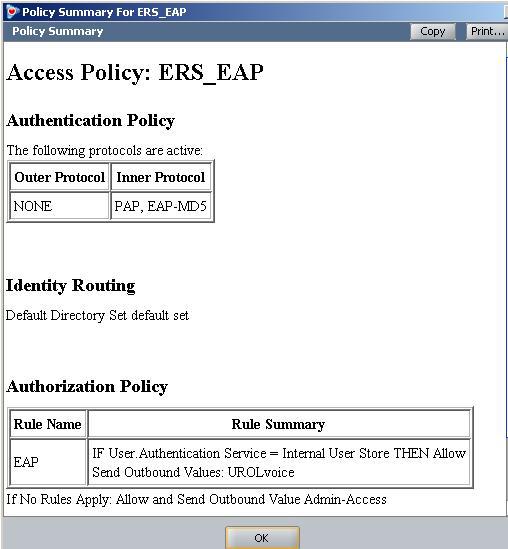
51 2.7.3 RADIUS Server Configuration Avaya Identity Engines IDE Step 1 Go to Site Configuration -> Access Policies -> RADIUS Right-click RADIUS and select New Access Policy. Enter a policy name, i.e. ERS- EAP as used in this example and click on OK when done Click on the policy we just created, i.e. ERS-EAP, and click on Edit via the Authentication Policy tab. Under Edit Authentication Policy window, select NONE -> EAP-MD5 and any additional authentication protocols you may require. Click on OK when done. Go to the Identity Routing tab and click on Edit. Check off the Enable Default Directory Set and click on OK when done. Go to the Authorization Policy tab and click on Edit. o o o Once the Edit Authorization Policy window pops up, click on Add under Rules and via the name pop-up box, enter a name, i.e. EAP as used in this example Click on the rule named EAP, click on New to add a new constraint. From Attribute Category, select User and scroll down and select Authentication Service. Select Equal To with Static Vlaue of Internernal User Store. Click on OK when done and OK one more time to exit Edit Authentication Policy. Clicking on the Access Policy Summary icon should display an Access Policy similar to that shown below 50
52 51
53 IDE Step 2 Go to Site Configuration -> Authenticators For this configuration example, we will create a new container named Avaya Switch o Under Authenticators, right-click default and add a new container with a container, add a name of Avaya Switch, and click OK when done Select Avaya Switch and click on click on New o Enter the settings as shown below making sure you select the policy we created above named ERS_EAP via Access Policy. Leave Enable Authenticator and Enable RADIUS Access checked. Click on OK when done. Please note, the RADIUS Shared Secret must match the secret entered on the switch 52
54 IDE Step 3 Add Users by going to Site Configuration -> Directories -> Internal Store -> Internal Users and click on New Add the EAP users by going to Directories>Internal Store>Internal Users. Next, enter the User Name and Password as shown below, i.e. User Name = phonea, Password = Phoneaeselab as per the Avaya IP Phone provisioning files used. Enter the user name for for the Avaya IP Phone EAP Supplicant via User Name: and enter the password for this user via Password and Confirm Password. Click on OK when done. If you wish, you can also change the expiry date via Password Expires if you do not wish to use the default setting of one year. Repeat again by clicking on New to add additional internal user names and passwords for each EAP Supplicant. Assuming we used the user credentials as per the provisioning file for the Avaya 1230 IP Phone and the MAC address of the Avaya 9640 IP Phone as the default user name, the internal store user-id s should like like the following o o Avaya 1230 IP Phone User Name = phonea, Password = Phoneaeselab Avaya 9640 IP Phone User Name = 001B4F581AD0, Password =
55 2.8 Auto Configuration with a Stackable Ethernet Routing Switch using EAP with NEAP and User Based Policy The Stackable Ethernet Routing Switch can be configured in one of two methods using NEAP (non-eap) to allow an IP phone without an EAP Supplicant access to the network. One method is to enable Non-EAPOL VoIP phone clients please see next configuration example. If you do wish to authenticate the IP Phone via RADIUS using EAP on the switch, but, without enabling an EAP Supplicant on the phone itself, the Allow Non-EAPOL client s (NEAP) option can be enabled where the switch itself will authenticate the IP Phone on its behalf. At this time, the Non-EAPOL VoIP phone clients feature is only supported on the Avaya 1100, 1200, and 2000 series IP Phones. For this example, we will demonstrate how to configure the Stackable Ethernet Routing Switch to allow for NEAP authentication using RADIUS for the IP Phones. We will also demonstrate using user based policies to apply QoS for the IP Phones. Hence, instead of configuring filters on the switch to apply QoS for the voice traffic, we can use a policy triggered by EAP to apply QoS to the voice VLAN. Any of the stackable Ethernet Routing switches support NEAP (ERS 2500, 4500 or 5000 series), however, only the ERS 5000 series supports user based policies. The Stackable Ethernet Routing Switch can be configured to accept both EAP and non-eap (NEAP) on the same port. In regards to non-eap, the switch can be configured to accept a password format using any combination of IP address and MAC address with or without port number. By default, the password format is set for IP address, MAC address, and port number. To apply QoS for the IP Phone sets, you can configure the QoS filters on the switch, use ADAC, or use user based policies (UBP) and trigger the policy via RADIUS authentication. As stated above, we will use UBP for this configuration example. Once the user based policies has been configured on a switch, the RADIUS server can reference the policy by using the name given to the UBP policy. User based policies (UBP) can be used with EAP and/or NEAP. This configuration example is in reference to diagram 1 and uses the base configuration from example
56 2.8.1 Stackable Switch Configuration In addition to the base configuration from Section 2.2, we will add the following: Enable NEAP on ports 3 to 11 on ERS-Stackable using the non-eap password format of MAC address only this will allow the IP Phone to be connected elsewhere in the network on a different switch without having to worry about port numbers and IP addresses Configure a user based policy (UBP) for non-eap IP Phones named voice that will remark both the DSCP and p-bit values to a CoS value of Premium only for tagged Voice VLAN 220 Configure the RADIUS server NEAP policy using Nortel specific option 562 with vendorassigned attribute number 110 and set the string value to UROLvoice. Please refer to Section 9 for more details regaring EAP configuration on Avaya Switches Please refer to Section 9 for more details regarding EAP configuration on Avaya Switches Please note that when setting up the RADIUS server policy for the NEAP group, the string always starts with UROL. In our example, we configured the ERS5000 with a user based policy named voice, hence the string value configured on the RADIUS server must be set to UROLvoice Configure RADIUS server ERS-Stackable Step 1 Add RADIUS server assuming we used a shared key of avaya this shared key must also be configured on the RADIUS server for this authenticator ERS-Stackable(config)#radius-server host key avaya Enable EAP globally ERS-Stackable Step 1 Enable non-eap (NEAP) ERS-Stackable(config)#eap multihost allow-non-eap-enable ERS-Stackable Step 2 Remove the default NEAP password format of IpAddr.MACAddr.PortNumber ERS-Stackable(config)#no eapol multihost non-eap-pwd-fmt ERS-Stackable Step 3 Enable NEAP password format of MAC address only ERS-Stackable(config)#eapol multihost non-eap-pwd-fmt mac-addr ERS-Stackable Step 4 Enable EAP user-based Policies ERS-Stackable(config)#eapol user-based-policies enable 55
57 ERS-Stackable Step 5 Enable EAP multihost NEAP policies ERS-Stackable(config)#eapol multihost non-eap-user-based-policies enable ERS-Stackable Step 6 Enable EAP globally ERS-Stackable(config)#eapol enable Enable EAP at interface level ERS-Stackable Step 1 Enable EAP on port 3-11 with NEAP, set the maximum allowable EAP and NEAP clients to 1, enable EAP multihost and enable RADIUS NEAP phone ERS-Stackable(config)#interface fastethernet 3-11 ERS-Stackable(config-if)#eapol status auto ERS-Stackable(config-if)#eapol multihost allow-non-eap-enable ERS-Stackable(config-if)#eapol multihost eap-mac-max 1 ERS-Stackable(config-if)#eapol multihost non-eap-mac-max 1 ERS-Stackable(config-if)#eapol multihost radius-non-eap-enable ERS-Stackable(config-if)#eapol multihost enable ERS-Stackable(config-if)#exit Configure Policy ERS-Stackable Step 1 Configure a policy using the name voice to filter on tagged VLAN 805 and remark DSCP and p-bit to Premium CoS. We will set the eval-order to 5 in case you wish to add additional filters in the future with a higher preference ERS-Stackable(config)#qos ubp classifier name voice vlan-min 805 vlan-max 805 vlan-tag tagged ethertype 0x0800 update-dscp 46 update-1p 6 eval-order 4 ERS-Stackable Step 2 Enable the UBP set ERS-Stackable(config)#qos ubp set name voice ERS-Stackable Step 3 Enable UBP ERS-Stackable(config)#qos agent ubp high-security-local The default ubp classifier action non-match action is for forward traffic. In older software releases for the ERS5500, this was not the case and you had to enter the command qos ubp set name voice drop-nm-action disable. You can quickly check to see if the software versions you are using require the drop non-match action by simply typing in qos ubp set name voice? and checking if the command drop-nm-action is displayed or not. 56
58 2.8.2 Verify Operations Verify EAP Global and Port Configuration Step 1 Verify that EAP has been enabled globally and the correct port members: ERS-Stackable# show eapol port 3-11 Result: EAPOL Administrative State: Enabled Port-mirroring on EAP ports: Disabled EAPOL User Based Policies: Enabled EAPOL User Based Policies Filter On MAC Addresses: Disabled Port: 3 Admin Status: Auto Auth: No Admin Dir: Both Oper Dir: Both ReAuth Enable: No ReAuth Period: 3600 Quiet Period: 60 Xmit Period: 30 Supplic Timeout: 30 Server Timeout: 30 Max Req: 2 RDS DSE: No Port: 11 Admin Status: Auto Auth: No Admin Dir: Both Oper Dir: Both ReAuth Enable: No ReAuth Period: 3600 Quiet Period: 60 Xmit Period: 30 Supplic Timeout: 30 Server Timeout: 30 Max Req: 2 RDS DSE: No Via the ERS-Stackable switch, verify the following information: Option EAPOL Administrative State EAPOL User Based Policies Admin Status Auth Verify Verify that the EAPOL is Enabled globally. Verify that EAPOL policies are Enabled globally. Verify that the EAP is enabled on ports 3 to 11 by verifying that the Admin Status is set to Auto. The value will be No even if the IP Phone has successfully authenticated. Only if there a Supplicant attached to the IP Phone and it 57
59 Verify EAP Multihost Configuration has successfully authenticated will this value change to Yes. Step 1 Verify that EAP multihost has been globally configured correctly: ERS-Stackable#show eapol multihost Result: Allow Non-EAPOL Clients: Enabled Use RADIUS To Authenticate Non-EAPOL Clients: Enabled Allow Non-EAPOL Clients After Single Auth (MHSA): Disabled Allow Non-EAPOL VoIP Phone Clients: Disabled EAPOL Request Packet Generation Mode: Multicast Allow Use of RADIUS Assigned VLANs: Disabled Allow Use of Non-Eapol RADIUS Assigned VLANs: Disabled Non-EAPOL RADIUS Password Attribute Format: MACAddr Non-EAPOL User Based Policies: Enabled Non-EAPOL User Based Policies Filter On MAC Addresses: Disabled Use most recent RADIUS VLAN: Disabled Step 2 Verify that EAP multihost has been configured correctly at interface level: ERS-Stackable#show eapol multihost interface 3-11 Result: Port: 3 MultiHost Status: Enabled Max Eap Clients: 1 Allow Non-EAP Clients: Enabled Max Non-EAP Client MACs: 1 Use RADIUS To Auth Non-EAP MACs: Enabled Allow Auto Non-EAP MHSA: Disabled Allow Non-EAP Phones: Disabled RADIUS Req Pkt Send Mode: Multicast Allow RADIUS VLANs: Disabled Allow Non-EAP RADIUS VLANs: Disabled Use most recent RADIUS VLAN: Disabled Port: 11 MultiHost Status: Enabled Max Eap Clients: 1 Allow Non-EAP Clients: Enabled Max Non-EAP Client MACs: 1 Use RADIUS To Auth Non-EAP MACs: Enabled Allow Auto Non-EAP MHSA: Disabled Allow Non-EAP Phones: Disabled RADIUS Req Pkt Send Mode: Multicast Allow RADIUS VLANs: Disabled Allow Non-EAP RADIUS VLANs: Disabled Use most recent RADIUS VLAN: Disabled 58
60 Via the ERS-Stackable switch, verify the following information: Option Allow Non-EAPOL Clients: Use RADIUS To Authenticate Non- EAPOL Clients: Non-EAPOL RADIUS Password Attribute Format: Non-EAPOL User Based Policies: Verify Verify that the non-eapol (NEAP) is Enabled globally. Verify the use RADUIS to authenticate non-eapol option is Enabled globally. Verify that the non-eap password format is set for MACAddr. Please note, some of the older software releases required a leading period. before and after the MAC address. Verity that the non-eapol user based policies is Enabled Verify EAP Multihost Status Step 1 Assuming the IP Phone via port 3 has successfully authenticated via EAP, use the following command to view the EAP status: ERS-Stackable# show eapol multihost non-eap-mac status Result: Port Client MAC Address State :24:00:0D:8D:29 Authenticated By RADIUS 4 00:24:00:0D:8D:AA Authenticated By RADIUS On the ERS-Stackable switch, verify the following information: Option Port Client MAC Address State Verify Display the ports where the IP Phone has successfully been authenticated. If the IP phone has successfully authenticated via NEAP, its MAC address should be shown. Verity that Authenticated By RADIUS is displayed 59
61 Verify EAP Policy Step 1 Use the following command to view the UBP Policy: ERS-Stackable# show qos ubp classifier Result: Id: 1 Name: voice Block: Eval Order: 5 Address Type: IPv4 Destination Addr/Mask: Ignore Source Addr/Mask: Ignore DSCP: Ignore IPv4 Protocol / IPv6 Next Header: Ignore Destination L4 Port Min: Ignore Destination L4 Port Max: Ignore Source L4 Port Min: Ignore Source L4 Port Max: Ignore IPv6 Flow Id: Ignore IP Flags: Ignore TCP Control Flags: Ignore IPv4 Options: Ignore Destination MAC Addr: Ignore Destination MAC Mask: Ignore Source MAC Addr: Ignore Source MAC Mask: Ignore VLAN: 805 VLAN Tag: Tagged EtherType: 0x p Priority: All Packet Type: Ignore Inner VLAN: Ignore Action Drop: No Action Update DSCP: 0x2E Action Update 802.1p Priority: Priority 6 Action Set Drop Precedence: Low Drop Storage Type: NonVolatile Via the ERS-Stackable switch, verify the following information: Option Name: Eval Order: Address Type: VLAN: EtherType: Action Update DSCP: Verify Verify the port number is correct, should be voice for this example. Verify the port number is correct, should be 5 for this example. Verify the Address Type is correct, should be IPv4 for this example. Verify VLAN is correct, should be 805 for this example. Verify the EtherType is correct, should be 0x0800 representing the IP for this example. Verify the DSCP value is correct, should be 0x2e (decimal 46) for this 60
62 example. Action Update 802.1p Priority: Verify the p-bit value is correct, should be 6 for this example Verify EAP Policy upon the NEAP client successfully authenticating Step 1 Assuming an IP Phone via port 3 and 4 has successfully authenticated via EAP, use the following command to view the UBP Policy: ERS-Stackable# show qos ubp interface Result: Id Unit Port Filter Set Name voice voice Via the ERS-Stackable switch, verify the following information: Option Port Filter Set Name Verify Verify the port number is correct according the NEAP authenticated IP Phones If the IP phone has successfully authenticated via NEAP, and if the RADIUS server has been configured correctly, the policy named voice will be displayed View EAP Policy Statistics Step 1 You can view the statistics by using the UBP reference and port number using the following command. Please note that the reference number for each port will be different. ERS-Stackable# show qos statistics port 3 Result: Id: Policy Name: UntrustedClfrs1 Classifier Unit/Port In-Profile Name Packets 1/

63 2.8.3 RADIUS Server Policy Setup Microsoft IAS Assuming the RADIUS server is a Windows 2003 server, via the IAS Remote Access Policies, go to your NEAP policy Advanced settings. The Vendor-Specific attribute should be setup as follows. Vendor Code : Nortel ; Nortel Specific Option 562 Vendor-assigned attribute o Attribute number : 110 o o Attribute format : String Attribute value : UROLvoice Step 1 Via IAS, assuming you have already started a NEAP policy, go the Advanced tab and click on Add and scroll down to Vendor-Specific and click on Add 62

 window, enter the following: o Vendor-assigned attribute number: 110 o")
64 Step 2 - Via the Multivalued Attribute Information window, click on Add. In the next window titled Vendor-Specific Attribute Information, click no the Select from list radio button and select Nortel Networks and click on the Yes, it conforms radio button. When finished, click on Configure Attributes. Step 3: Via the Configure VSA (RFC compliant) window, enter the following: o Vendor-assigned attribute number: 110 o Attribute formate: String o Attribute value: UROLvoice Click on OK when done. 63

65 Step 4 When completed, the profile should be as that displayed below. 64

66 Avaya Identity Engines Ignition Server Using the base IDE configuration in Section 2.7.3, we will simply add the appropriate outbound attribute to the Access Policy. Please note, the Nortel vendor specific attributes are already added and can be viewed by going to Site Configuration -> Provisioning -> Vendors/VSAs and scrolling down and selecting Nortel -> VSA Definitions. For this example, we will use the VSA Definition ERS-User-Based-Policy. IDE Step 1 Go to Site Configuration -> Provisioning -> Outbound Attributes -> New When the New Outbound Attribute window pops up, enter the following as shown below. As shown below, in this example, we simply named the outbound attribute UROL 65

67 IDE Step 2 Go to Site Configuration -> Provisioning -> Outbound Values -> New When the Outbound Value Details window pops up, enter a name, i.e. UROLvoice as used in this example, and click on New When the Outbound Value Instance window pops up, enter the following as shown below. Please note, the String value must be UROLvoice as voice is the name of the policy defined on the switch in this configuration example. Click OK twice when done 66
 From the All Outbound Values windows, select UROLvoice and then click on the lessthan arrow key Click OK when done This should move the outbound attribute named UROLvoice to the")
68 IDE Step 3 Go to Site Configuration -> Access Policies-> RADIUS -> ERS_EAP -> Authorization Policy -> Edit (assuming we are using the policy we configured in Section named ERS_EAP ) From the All Outbound Values windows, select UROLvoice and then click on the lessthan arrow key Click OK when done This should move the outbound attribute named UROLvoice to the Provision With window as shown below 67
69 68
70 2.9 Auto Configuration with a Stackable Ethernet Routing Switch using EAP with Non-EAP-Phone Support and ADAC (LLDP detection) As explained in the configuration example in Section 2.8, the Stackable Ethernet Routing Switch can be configured in one of two methods using NEAP (non-eap) to allow an IP phone without an EAP Supplicant access to the network. For this example, we will enable Non-EAPOL VoIP phone clients. This is by far the easiest method to authorize certain Avaya IP Phones on a switch as it does not require any RADIUS setup. The Avaya IP Phone is detected by examining the phone signature contained in the DHCP Discovery packet sent by the IP phone. If the signature is valid, the IP phone is allowed access to the network. At this time, the Non-EAPOL VoIP phone clients feature is only supported on the Avaya 1100, 1200, and 2000 series IP Phones. This configuration example is in reference to diagram 1 and uses the base configuration from example 2.2. Please note that non-eap support for IP phones is only supported on Avaya IP Phones and requires that DHCP be enabled. The IP phone is authenticated based on the DHCP signature. Do not enable EAP on the phone. Also, do not enable Guest-VLAN. 69
71 2.9.1 Stackable Switch Configuration Please refer to Section 9 for more details regarding EAP configuration on Avaya Switches Enable ADAC at interface level ERS-Stackable Step 1 Enable ADAC on port members 3 to 11, set the ADAC detection to LLDP only, and enable the ADAC tag mode to tagged frames and untag the default VLAN ERS-Stackable(config)#interface fastethernet 3-11 ERS-Stackable(config-if)#adac detection lldp ERS-Stackable(config-if)#no adac detection mac ERS-Stackable(config-if)#adac tagged-frames-tagging untag-pvid-only ERS-Stackable(config-if)#adac enable ERS-Stackable(config-if)#exit Enable LLDP-MED ERS-Stackable Step 1 Enable LLDP-MED on port 3 to 11 ERS-Stackable(config)#interface fastethernet 3-11 ERS-Stackable(config-if)#lldp tx-tlv local-mgmt-addr port-desc sys-cap sys-desc sys-name ERS-Stackable(config-if)#lldp status txandrx config-notification ERS-Stackable(config-if)# lldp tx-tlv med extendedpse location med-capabilities network-policy ERS-Stackable(config-if)#exit Configure RADIUS server ERS-Stackable Step 1 Add RADIUS server ERS-Stackable(config)#radius-server host key Enter key: ****** Confirm key: ****** Enable EAP globally ERS-Stackable Step 1 Enable EAP non-eap phone ERS-Stackable(config)#eapol multihost non-eap-phone-enable ERS-Stackable Step 2 Enable EAP ERS-Stackable(config)#eapol enable 70
72 Enable EAP at interface level ERS-Stackable Step 1 Enable EAP on ports 3 to 11 with non-eap-phone and use-radiusassigned-vlan enabled ERS-Stackable(config)#interface fastethernet 3-11 ERS-Stackable(config-if)#eapol multihost non-eap-phone-enable ERS-Stackable(config-if)#eapol multihost eap-mac-max 1 ERS-Stackable(config-if)#eapol multihost enable ERS-Stackable(config-if)#eapol status auto ERS-Stackable(config-if)#exit 71
73 2.9.2 Verify Operations Assuming we have an Avaya IP phone with a Supplicant connected to port 7 and an Avaya IP Phone connected to port 8 with the following characteristics: Port 7: o o Port 8: o Avaya IP Phone 1230 with MAC address d-8d-29 Supplicant with MAC address 00:02:A5:E9:00:28 Avaya IP Phone 1230 with MAC address d-8d-aa Verify EAP Global and Port Configuration Step 1 Verify that EAP has been enabled globally and the correct port members: ERS-Stackable#show eapol port 3-11 Result: EAPOL Administrative State: Enabled Port: 3 Admin Status: Auto Auth: No Admin Dir: Both Oper Dir: Both ReAuth Enable: No ReAuth Period: 3600 Quiet Period: 60 Xmit Period: 30 Supplic Timeout: 30 Server Timeout: 30 Max Req: 2 RDS DSE: No Port: 7 Admin Status: Auto Auth: Yes Admin Dir: Both Oper Dir: Both ReAuth Enable: No ReAuth Period: 3600 Quiet Period: 60 Xmit Period: 30 Supplic Timeout: 30 Server Timeout: 30 Max Req: 2 RDS DSE: No Port: 8 Admin Status: Auto Auth: Yes 72
74 Via the ERS-Stackable switch, verify the following information: Option EAPOL Administrative State Auth Verify Verify that the EAPOL is Enabled globally. For any port that has a Supplicant which has successfully been authenticated, the Auth state should be Yes Verify EAP Multihost Configuration Step 1 Verify that EAP multihost has been globally configured correctly: ERS-Stackable#show eapol multihost Result: Allow Non-EAPOL Clients: Disabled Use RADIUS To Authenticate Non-EAPOL Clients: Disabled Allow Non-EAPOL Clients After Single Auth (MHSA): Disabled Allow Non-EAPOL VoIP Phone Clients: Enabled EAPOL Request Packet Generation Mode: Multicast Allow Use of RADIUS Assigned VLANs: Disabled Allow Use of Non-Eapol RADIUS Assigned VLANs: Disabled EAPOL Reauthentication Security Mode: Fail on RADIUS Timeout Non-EAPOL RADIUS Password Attribute Format: IpAddr.MACAddr.PortNumber Use most recent RADIUS VLAN: Disabled Via the ERS-Stackable switch, verify the following information: Option Allow Non-EAPOL VoIP Phone Clients Verify Verify the allow non-eapol VoIP Phone Clients option is Enabled globally. 73
75 Verify EAP Multihost Port configuration Step 1 Verify that EAP mulltihost configuration: ERS-Stackable#show eapol multihost interface 3-11 Result, i.e. for port 3: Port: 3 MultiHost Status: Enabled Max Eap Clients: 1 Allow Non-EAP Clients: Disabled Max Non-EAP Client MACs: 1 Use RADIUS To Auth Non-EAP MACs: Disabled Allow Auto Non-EAP MHSA: Disabled Allow Non-EAP Phones: Enabled RADIUS Req Pkt Send Mode: Multicast Allow RADIUS VLANs: Disabled Allow Non-EAP RADIUS VLANs: Disabled RADIUS Timeout Mode: Fail Use most recent RADIUS VLAN: Disabled Port: 11 MultiHost Status: Enabled Max Eap Clients: 1 Allow Non-EAP Clients: Disabled Max Non-EAP Client MACs: 1 Use RADIUS To Auth Non-EAP MACs: Disabled Allow Auto Non-EAP MHSA: Disabled Allow Non-EAP Phones: Enabled RADIUS Req Pkt Send Mode: Multicast Allow RADIUS VLANs: Disabled Allow Non-EAP RADIUS VLANs: Disabled RADIUS Timeout Mode: Fail Use most recent RADIUS VLAN: Disabled Via the ERS-Stackable switch, verify the following information: Option Verify MultiHost Status Verify that the MultiHost status is Enabled on port 3 to 11. Max Eap Client Max Non-EAP Client MACs Allow Non-EAP Phones Verify that the maximum EAP client is set to 1. If not, check your configuration Verify that the maximum non-eap client is set to 1. If not, check your configuration Verify that Allow Non-EAP Phone is set to Enabled. If not, check your configuration 74
76 Verify EAP Multihost Status Step 1 Assuming the Supplicant via port 8 has successfully authenticated via EAP, use the following command to view the EAP status: ERS-Stackable#show eapol multihost status Result: Port Client MAC Address Pae State Backend Auth State :02:A5:E9:00:28 Authenticated Idle =========Neap Phones============ d-8d d-8d-aa Via the ERS-Stackable switch, verify the following information: Option Client MAC Address Pae State Neap Phones Verify Verify the actual Supplicant MAC. For this example, this should be 00:02:A5:E9:00:28 on port 7. Verify the actual Supplicant Pae State. If the Supplicant has successfully authenticated, the Pae State should be displayed as Authenticated Verify the actual MAC for the Avaya IP Phone sets. For this example, this should be d-8d-29 on port 7 and d-8d-aa on port 8 75
77 2.10 Avaya IP Phone DHCP and Provisioning Files Details regarding various Avaya IP Phone DHCP and configuration file paramteters are listed in Appendix A. List below are the mimimum settings required for this configuration example DHCP Settings The following assumptions apply: The voice VLAN id is 805 We will use the HTTP provisioning server as illustrated in diagram 1 using an IP address of o o The file path for the Avaya 9640 IP Phone is 9600/96xxH323_ The file path for the Avaya 1230 IP Phone is phone_prov_files DHCP Server Step 1 Data VLAN DHCP Scope settings for the Avaya 1230 IP Phone Option 191 String Value VLAN-A:805. DHCP Server Step 1 Data VLAN DHCP Scope settings for the Avaya 9640 IP Phone Option 242 String Value L2Q=1 L2QVLAN=805 VLANTEST=60 DHCP Server Step 2 Voice VLAN DHCP Scope settings for the Avaya 1230 IP Phone Option 224 String Value Nortel-i2004-B,prov= DHCP Server Step 2 Voice VLAN DHCP Scope settings for the Avaya 9640 IP Phone Option 242 String Value HTTPSRVR= HTTPDIR= 9600/96xxH323_
78 Provisioning Files The following shows the configuration files used for this example. Avaya 1230 IP Phone provisioning Files Files include system.prv, 1230.prv, and D8DAA.prv (includes EAP MD5 configuration) system.prv file=td; s1ip= ; p1=4100; a1=1; rl=2; s2ip= ; p2=4100; a2=1; r2=2; 1230.prv lldp=y; igarp=y; vq=y; vlanf=y; pc=y; dq=n; pcuntag=y; reg=00:24:00:0d:8d:aa,cs1k,s1s2,600, ; D8DAA.prv eap=md5; eapid1=phoneb; eappwd=phonebeselab; Avaya 9640 IP phone provisioning File File used is 46xxxsettings.txt (includes EAP MD5 configuration) 46xxsettings.txt SET HTTPSRVR SET HTTPDIR 9600\96xxH323_ SET VLANTEST 60 SET PROCSTAT 0 SET PROCPSWD SET PHY1STAT 1 SET PHY2STAT 1 SET MCIPADD SET DOT1XSTAT 2 SET DOT1X 0 SET DOT1XEAPS "MD5" 77
79 2.11 Avaya Energy Saver (AES) In reference to Diagram 1, assume we wish to enable AES to ERS-Stackable with the following schedule: Activate AES during the week from Monday to Friday nighttime from 7:00 pm to 6:30 am Deactivate AES on Saturday from 7:00 am to 5:00 pm Go to configuration mode. ERS-Stackable: Step 1 - Enter configuration mode ERS-Stackable>enable ERS-Stackable#config terminal Add SNTP Server ERS-Stackable: Step 1 Add an SNTP server ERS-Stackable(config)#sntp server primary address ERS-Stackable(config)#sntp enable Add Avaya Energy Saver configuration ERS-Stackable: Step 1 Enable AES at interface level ERS-Stackable(config)#interface fastethernet all ERS-Stackable(config-if)#energy-saver enable ERS-Stackable(config-if)#exit ERS-Stackable: Step 2 Enable AES schedule ERS-Stackable(config)#energy-saver schedule weekday 06:30 deactivate ERS-Stackable(config)#energy-saver schedule weekday 19:00 activate ERS-Stackable(config)#energy-saver schedule saturday 07:00 deactivate ERS-Stackable(config)#energy-saver schedule saturday 17:00 activate ERS-Stackable(config)#energy-saver enable For test purposes, you can activate/deactivate AES by issuing the following commands from the CLI Privileged level: ERS-Stackable#energy-saver activate ERS-Stackable#energy-saver deactivate 78
80 Verify operations Verify SNTP SNTP must be configured and running for AES to operate. The switch must have SNTP enabled to correctly obtain the time for operation of AES if the scheduler is configured. Step 1 Verify SNTP is configured ERS-Stackable#show sntp Result: SNTP Status: Enabled Primary server address: Secondary server address: Sync interval: 24 hours Last sync source: Primary server sync failures: 0 Secondary server sync failures: 0 Last sync time: :43:31 GMT-01:00 Next sync time: :43:31 GMT-01:00 Current time: :52:16 GMT-01:00 Step 2 Verify clock ERS-Stackable#show clock Result: Current SNTP time : :51:11 GMT-01:00 Summer time recurring is set to: start: on Sunday in the 4th week of March at 02:00 end: on Sunday in the 4th week of October at 02:00 Offset: 60 minutes. Summer time is set to: start: 29 March 2010 at 02:00 end: 30 October 2010 at 03:00 Offset: -60 minutes. Time zone will be 'EDT' Time zone is set to 'EST', offset from UTC is -02:00 79
81 Verify AES Use the following commands to verify AES is operational. In this example, we will show the effect of AES with a model 1120E IP phone connected to port 1/9. Prior to AES activation, the 1120E should be operating at 1000Mbps full duplex. After AES activation, the 1120E should be operating at 10Mbps full duplex. Step 1 Verify AES is configured at interface level ERS-Stackable#show energy-saver interface Result: Unit/Port AES State PoE Savings PoE Priority /1 Enabled Disabled Low 1/2 Enabled Disabled Low Step 2 Verify Port is delivering PoE power; the following shows the power measured prior to and after AES activation ERS-Stackable#show poe-power-measurement 1/9 Result: The following shows the PoE power delivered prior to AES activation: Unit/Port Volt(V) Current(mA) Power(Watt) / The following show the PoE power delivered after AES activation: Unit/Port Volt(V) Current(mA) Power(Watt) /
82 Step 3 Verify Ethernet interface speed; the following shows the port speed prior to and after AES activation ERS-Stackable#show poe-port-status 1/9 Result: The following displays the interface speed prior to AES activation: Status Auto Flow Unit/Port Trunk Admin Oper Link LinkTrap Negotiation Speed Duplex Control /9 Enable Up Up Enabled Enabled 1000Mbps Full Symm The following displays the interface speed after AES is activated: Status Auto Flow Unit/Port Trunk Admin Oper Link LinkTrap Negotiation Speed Duplex Control /9 Enable Up Up Enabled Enabled 10Mbps Full Disable Step 4 Verify AES globally settings ERS-Stackable#show energy-saver Result: Avaya Energy Saver (AES): Enabled AES PoE Power Saving Mode: Disabled AES Efficiency-Mode Mode: Disabled Day/Time: Tuesday 20:58:58 Current AES state: AES is Active Step 5 Verify AES schedule ERS-Stackable#show energy-saver schedule Result: Day Time Action Monday 06:30 Deactivate Monday 19:00 Activate Tuesday 06:30 Deactivate Tuesday 19:00 Activate Wednesday 06:30 Deactivate Wednesday 19:00 Activate Thursday 06:30 Deactivate Thursday 19:00 Activate Friday 06:30 Deactivate Friday 19:00 Activate Saturday 07:00 Deactivate Saturday 17:00 Activate 81
83 Step 6 Verify AES power savings; the following shows the power savings after AES activation ERS-Stackable# show energy-saver savings Result: Prior to AES activation: Unit# Model Switch Capacity Saving PoE Saving TFD-PWR 0.0 watts 0.0 watts TOTAL 0.0 watts 0.0 watts ============================================================= After AES activation: Unit# Model Switch Capacity Saving PoE Saving TFD-PWR 2.7 watts 0.0 watts TOTAL 3.6 watts 0.0 watts ============================================================= 82
84 2.12 DHCP Server Setup The following setup applies to configuring a DHCP server for auto configuration. Depending on the Avaya IP phone series used, the DHCP options can vary. VLAN Setting using DHCP Double DHCP is a term used where the IP Phone learns the voice VLAN Id using DHCP. From a default setting, all IP Phones send out traffic untagged and use DHCP to get an IP address. Providing you configure the data VLAN scope with the correct DHCP options, the IP Phone will learn the voice VLAN ID from the data VLAN and then proceed to request for a new IP address now via the tagged voice VLAN. This method provides separation for voice and data traffic allowing for a PC or any other data device to be directly connected to the IP Phone set. The IP Phone can be also be setup to either leave the data traffic untagged or tag the data VLAN using a different VLAN Id other than that of the voice VLAN. Depending on the Avaya IP Phone model, the VLAN and IP address may be cached so this double DHCP process actually only occurs once. The Avaya 1600, 4600, and 9600 series cache both the IP address and VLAN Id. Hence, upon a power cycle, the Avaya IP Phone will request an IP address directly via the tagged voice VLAN without having to perform double DHCP. The Avaya 1100, 1200, and 2000 series have an option to cache the IP address, but, this only comes into effect if a DHCP server is unreachable in other words, the IP phone will continue to perform double DHCP unless the DHCP server is unreachable. Depending on the Avaya IP phone model, the following DHCP option should be configured. Details on each on these items are described in detail latter in this document and in the appendixes. Avaya 1100, 1200, and 2000 Series o Option 191 Avaya 4600 Series o Option 176 Avaya 1600 and 9600 Series o Option 242 IP Phone Settings using DHCP A limited set of IP phone settings can be set by DHCP. Details are covered in detail later in this document and in the appendixes. More detailed IP phone configuration should be done using a provisioning server which can be set via the voice VLAN. Depending on the Avaya IP phone model, the following DHCP option should be configured. Avaya 1100, 1200, and 2000 Series o Option 128- prior to UNIStim firmware release 2.2 Call Server settings only o Option 128, 131, 144, 157, 188, 191, 205, 219, 223, 224, 227, 230, 232, 235, 238, 241, 244, 247, 251 or UNIStim firmware release 2.2 and greater Extended IP phone settings 83
85 Avaya 4600 Series o Option 176 Avaya 1600 and 9600 Series o Option 242 The following configuration example shows how to setup a DHCP server for Avaya IP phone. In our example, a Windows 2003 server will be used. 84

86 Windows 2003 DHCP Configuration For this configuration example, we will create the following Option 224 and 191 to be used for the Avaya 1100, 1200, and 2000 Series Series IP phones Option 242 to be used for the Avaya 1600 and 9600 Series IP Phones Default DHCP Options Windows 2003 Server Step 1 Go to the following Start->Administrative Tools->DHCP Windows 2003 Server Step 2 Create DHCP Options by high-lighting the name on of your DHCP server from the top menu and select the following Action -> Set Predefined Options -> Add 85

87 Windows 2003 Server Step 3 Add a new DHCP option, create DHCP option 191 After clicking on Add, fill in the information as shown below for the DHCP option with the identifier set to 191. Name: Any name you like Set Date type: String Code: 191 Description: Add any comments if you like 86
88 Windows 2003 Server Step 4 Create DHCP option 224 Select Add again and fill in the information as shown below for the DHCP option with the identifier set to 224. Name: Any name you like Set Date type: String Code: 224 Description: Add any comments if you like Windows 2003 Server Step 5 Create DHCP option 242 Select Add again and fill in the information as shown below for the DHCP option with the identifier set to 242. Name: Any name you like Set Date type: String Code: 242 Description: Add any comments if you like 87

89 Windows 2003 Server Step 6 Right-click Scope Option from the data VLAN DHCP scope and select Configure Options. Scroll down to the DHCP Options you just created and check off the box to enable the 191 Option Add the appropriate IP address scope, default router, and other various DHCP options for the data VLAN. Once you complete this step, you can then add the required DHCP options for the Avaya IP Phone VLAN information. The example below shows the DHCP scope for the Data VLAN using DHCP Option 191 for the Avaya 1100, 1200, or 2000 series IP Phones. The example below shows the string value pertaining for the Data VLAN where the following string is added to set the Avaya IP phone to tag the voice VLAN using VLAN ID 805: VLAN-A:805. There must be a colon (:) separating the Hardware Revision from the VLAN ID. The string must also end in a period (.) 88

90 Windows 2003 Server Step 7 Right-click Scope Option from the data VLAN DHCP scope then select Configure Options. Scroll down to the DHCP Options you just created and check off the box to enable the 242 Option Add the appropriate IP address scope, default router, and other various DHCP options for the data VLAN. Once you complete this step, you can then add the required DHCP options for the Avaya IP Phone VLAN information. The example below shows the DHCP scope for the Data VLAN using DHCP Option 242 for the Avaya 1600 or 9600 series IP Phones. The example below shows the string value pertaining for the Data VLAN where the following string is added to set the Avaya IP phone to tag the voice VLAN using VLAN ID 60: L2Q=1,L2QVLAN=805,VLANTEST=60 The string must have a comma (,) between each parameter with no spaces. 89
91 Windows 2003 Server Step 8 Right-click Scope Option from the voice VLAN DHCP scope and select Configure Options. Scroll down to the DHCP Options you just created and check off the box to enable the 242 Option Add the appropriate IP address scope, default router, and other various DHCP options for the voice VLAN. Once you complete this step, you can then add the required DHCP options for the Avaya IP Phone VLAN information. The example below shows the DHCP scope for the Voice VLAN using DHCP Option 242 for the Avaya 9600 series IP Phones as used in this example. The example below shows the string value pertaining for the Voice VLAN assuming the Avaya 9600 IP Phones are using H.323 and retrieving the configuration file using HTTP from the directory 9600/96xxH323_ In this directory, it should contain the appropriate files, assuming the Avaya 9600 series is used, it should contain the 96xxupgrade.txt and 46xxsettings.txt files With a provision server using HTTP o HTTPSRVR= ,HTTPDIR= 9600/96xxH323_ Without a provision server: o MCIPADD= ,VLANTEST=60 90

92 Windows 2003 Server Step 9 Right-click Scope Option from the voice VLAN DHCP scope and select Configure Options. Scroll down to the DHCP Options you just created and check off the box to enable the 224 Option Add the appropriate IP address scope, default router, and other various DHCP options for the voice VLAN. Once you complete this step, you can then add the required DHCP options for the Avaya IP Phone VLAN information. The example below shows the DHCP scope for the Voice VLAN using DHCP Option 224 for the Avaya 1100 or 1200 series IP Phones. The example below shows the string value pertaining for the Voice VLAN assuming the Avaya 1100 or 1200 IP Phones use HTTP to get it s provisioning files via the directory named phone_prov_files With a provision server using HTTP o Nortel-i2004-B,prov= With a provision server using TFTP o Nortel-i2004-B,prov= /phone_prov_files; Without a provision server: o Nortel-i2004-B,s1= ;p1=4100;a1=1;r1=5;s2= ;p1=4100; a1=1;r1=5; 91
 Manager and under the name of your IIS server, go to Web Sites -> Default Web Site -> phone_prov_files -> Properties (in our")
93 Please note that if using a Windows 2003 server, it may not associate the Avaya 1100/1200 series provision file extention of.prv with text files. To change this, open Windows 2003 Internet Information Services (IIS) Manager and under the name of your IIS server, go to Web Sites -> Default Web Site -> phone_prov_files -> Properties (in our example, phone_prov_files is the name of the directory storing the Avaya 1100/1200 series provision files). Next, go to HTTP Headers -> MIME Types -> New and under Extention, enter.prv and under MIME Type, enter text. 92
94 3. Avaya IP Deskphones Avaya offers a variety of IP Deskphones. The following sections highlight the major features of each of these series of phones along with information on how to access the configuration menus Series IP Deskphones Feature Comparison Feature Display Size / Type Avaya 2000 Series IP Deskphones IP Phone IP Phone IP Phone 2007 IP Deskphone 3x24 Character LCD 4x24 Character LCD # of Lines 1 4 8x24 Character LCD 6+ Varies w/config 320x240 Pixels Color Touch screen LCD 6+ Varies w/config Headset Jack Handsfree Listen only Yes Yes Yes 802.3af PoE Class Class 2 Class 2 Class 2 Class 3 Two Port Switch No Yes Yes Yes Gigabit Ethernet No No No No USB Ports Support for Expansion Module Attachment No Yes (Current 200x KEM) Yes (Current 200x KEM) Bluetooth Headset No No No No XAS (Application Gateway) Support EAP (802.1x) Yes Yes No Yes Yes Yes Yes Yes (Phase II only) Yes 802.1AB Yes Yes (Phase II only) Yes (Phase II only) Yes Table 1: Avaya IP Deskphones 2000 Series 1 The IP Phone 2001, IP Phone 2002 and IP Phone 2002 are no longer manufactured. 93

95 3.1.2 Accessing the Configuration Menu (2001/2002/2004) To access the configuration menu power cycle the IP Phone 2001/2002/2004 and then wait until Nortel appears on the LCD panel. At this point, press the following keys in order from 1 to 4: Function key 1, Function key 2, Function key 3, and finally Function key Function Keys Figure 3: IP Phone 2004 Access Configuration Menu Figure 4: IP Phone 2002 Access Configuration Menu 94
96 To power cycle the IP Phone 2004 via the front panel, press the following keys in order from 1 to 9: Mute key, up Navigation key, down Navigation key, up Navigation key, down Navigation key, up Navigation key, Mute, 9, and finally the Goodbye key. To power cycle the IP Phone 2001 via the front panel, press the following keys in order from 1 to 9: # key, up Navigation key, down Navigation key, up Navigation key, down Navigation key, up Navigation key, #, 9, and finally the Goodbye key , 2,4, 3, Figure 5: IP Phone 2004 Power Cycle Phone Set 95
97 8 2,4, 3, 1, 9 Figure 6: IP Phone 2002 Power Cycle Phone Set 96
98 3.1.3 Configuration Menu on Phase II IP Phone 2001, Phase II IP Phone 2002 and Phase II IP Phone 2004 The single-line based configuration menu structure below presents the complete configuration menu now available on the Phase II IP Phone 2001, Phase II IP Phone 2002 and Phase II IP Phone 2004: EAP Enable?[0-N,1-Y]:0 if 1 DeviceID:[ ] Password: LLDP Enable?[0-N,1-Y]:0 DHCP? [0-N, 1-Y]:1 if 0 SET IP: xxx.xxx.xxx.xxx NETMSK: xxx.xxx.xxx.xxx DEF GW: xxx.xxx.xxx.xxx S1 IP: xxx.xxx.xxx.xxx S1 PORT: S1 ACTION: S1 RETRY COUNT: S2 IP: xxx.xxx.xxx.xxx S2 PORT: S2 ACTION: S2 RETRY COUNT: else if 1 DHCP:0-Full,1-Partial:1 if 1 S1 IP: xxx.xxx.xxx.xxx S1 PORT: S1 ACTION: S1 RETRY COUNT: S2 IP: xxx.xxx.xxx.xxx S2 PORT: S2 ACTION: S2 RETRY COUNT: Speed[0-A,1-10,2-100]:0 if 1 or 2 Duplex[0-A,1-F,2-H]:0 Cfg XAS?[0-N, 1-Y]:1 if 1 XAS IP: xxx.xxx.xxx.xxx Voice 802.1Q[0-N,1-Y]:1 if 1 VOICE VLAN?[0-N,1-Y]:0 if 1 VLAN Cfg?0-Auto,1-Man :1 The VLAN Cfg menu is only presented if DHCP is provisioned to Partial or Full above or if LLDP is enabled above. if 0 LLDP MED? [0-N, 1-Y] :0 97
99 The LLDP MED menu is only presented if LLDP is enabled above. if 0 LLDP VLAN? [0-N,1-Y] :0 The LLDP VLAN menu is only presented if LLDP is enabled above. if 0 DHCP? [0-N, 1-Y] :0 The DHCP menu is only presented if DHCP is provisioned to Partial or Full above. else if 1 VOICE VLAN ID : VLANFILTER?[0-N, 1-Y] :0 Ctrl pbits[0-7,8-au] :8 Media pbits[0-7,8-au] :8 PC Port? [0-OFF,1-ON] :1 This menu item, and submenus, are not available on the IP Phone if 1 Speed[0-A,1-10,2-100]:0 if 1 or 2 Duplex[0-A,1-F,2-H]:0 Data 802.1Q[0-N,1-Y]:1 if 1 DATA VLAN? [0-N, 1-Y]:0 if 1 DATA VLAN Cfg?0-A,1-M:0 This DATA VLAN Cfg menu item is only presented if LLDP is enabled above. if 1 DATA VLAN ID: Data pbits[0-7,8-au] :8 PCUntagAll?[0-N,1-Y]:0 Cached IP? [0-N, 1-Y]:0 This Cached IP menu item is only presented if DHCP is provisioned to Yes above and Voice VLAN is not provisioned as Auto. GARP Ignore?[0-N,1-Y]:0 PSK SRTP?[0-N, 1-Y]:0 98
. If prompted for Enter Administration Password:, then press the following keys in sequence: 2, 6, 5, 6, 7, *, 7, 3, 8, OK.")
100 3.1.4 Accessing the Configuration Menu (2007 IP Deskphone) To access the configuration menu, power cycle the 2007 IP Deskphone and when the Avaya logo appears in the middle of the display, immediately press the following key in sequence: 0, 0, 7, and star (*). If prompted for Enter Administration Password:, then press the following keys in sequence: 2, 6, 5, 6, 7, *, 7, 3, 8, OK. Using Navigation Keys scroll down/up to select the configuration options. As an alternative, use the USB port on the back of the IP Phone to use a mouse to scroll and select configuration options. Figure 7: IP Phone 2007 Phone Set Configuration Menu on the 2007 IP Deskphone The full-screen based configuration menu structure below presents the complete configuration menu available on the 2007 IP Deskphone as of UNIStim 4.2 (0621C7G). For other releases of software, please refer to the associated Product Bulletin or ReadMe File. EAP Mode: [Disable, MD5, PEAP, TLS] ID 1: ID 2: Password: Enable 802.1ab (LLDP): [] DHCP: [No, Yes] Set IP: xxx.xxx.xxx.xxx 99
101 Net Mask: xxx.xxx.xxx.xxx Gateway: xxx.xxx.xxx.xxx DNS1 IP: xxx.xxx.xxx.xxx DNS2 IP: xxx.xxx.xxx.xxx CA Server: Domain Name: Hostname: S1 IP: xxx.xxx.xxx.xxx Port: S1 Action: Retry: S1 PK: FFFFFFFFFFFFFFFF S2 IP: xxx.xxx.xxx.xxx Port: S2 Action: Retry: S2 PK: FFFFFFFFFFFFFFFF Ntwk Port Speed: [Auto, 10BT, 100BT] Ntwk Port Duplex: [Auto, Force Full, Force Half] Phone Mode [Hidden, Full, Reduced] XAS Mode [Text Mode, Graphical, Full Screen, Secure Graphical, Secure Full Screen] XAS IP: xxx.xxx.xxx.xxx Port: Enable Voice 802.1Q: [] VoiceVLAN: [No VLAN, Auto, Enter VLAN ID] The Auto option in the VoiceVLAN menu is only available if DHCP is provisioned to Yes above or if LLDP is enabled above, respectively. VLAN Filter : [] Ctrl Priority Bits: [Auto, 0, 1, 2, 3, 4, 5, 6, 7] Media Priority Bits: [Auto, 0, 1, 2, 3, 4, 5, 6, 7] Enable Avaya Auto QoS: [] DSCP Override: [] This DSCP Override menu item is only presented if Enable 802.1ab (LLDP) is enabled above and Control DSCP or Media DSCP are not manually set below Control DSCP: xx Media DSCP: xx Enable PC Port: [] PC Port Speed: [Auto, 10BT, 100BT] PC Port Duplex: [Auto, Force Full, Force Half] Enable Data 802.1Q: [] DataVLAN: [No VLAN, Enter VLAN ID] Data Priority Bits: [Auto, 0, 1, 2, 3, 4, 5, 6, 7] PC-Port Untag All: [] Enable Stickiness [] Cached IP: [] This Cached IP menu item is only presented if DHCP is provisioned to Yes above. Ignore GARP: [] 100
102 Enable SRTP PSK: [] SRTP PSK Payload ID: [96, 115, 120] Provision: xxx.xxx.xxx.xxx Provision Zone ID: The 2007 IP Deskphone contains a password protection mechanism to lock out access to the Local Tools menu including the Network Configuration menu. If enabled, access to the Local Tools menu is password protected and the password is prompted by a pop up window. One must type the password from the dial pad and press the center of the navigation cluster (enter key) to enter the Network Configuration menu. The default password is 26567*738 (color*set), but this password can be changed by the system administrator. When an incorrect password is entered, the Local Tools menu is not opened. To thwart password guessing, only 3 incorrect password entries in a row are allowed. After the 3 rd incorrect entry, the password entry is ignored for 5 minutes. During this period of time, the password prompt is displayed and the entered digits accepted; however, the phone will not process the incoming digits. The password prompt window simply closes and the behavior is identical to that of an incorrect password entry. The user will assume the incorrect password has been entered and try again. Thus even if the correct password is guessed during the 5 minute period, it will be ignored. This effectively reduces the guess entry rate to 3 guesses every 5 minutes. Once the password has been entered, access to the Local Tools menu remains active for 5 minutes. During the 5 minutes, the menu can be freely navigated, exited and entered without being prompted again for the password. When the 5 minutes expires, the menu is closed. The password must be reentered to access the Local Tools menu. 101
103 Series IP Deskphones Feature Comparison Feature Display Size / Type Feature Keys (Excluding Enter + NAV) 1110 IP Deskphone 144x32 Pixels Graphical LCD Avaya 1100 Series IP Deskphone 1120E IP Deskphone 240x80 Pixels Grayscale LCD # of Lines E IP Deskphone 240x160 Pixels Grayscale LCD 1150E IP Deskphone 240x160 Pixels Grayscale LCD 1165E IP Deskphone 320x240 Pixels 24-bit Color LCD Varies w/config 6+ Varies w/config 8+ Varies w/config Headset Jack Handsfree Listen only Yes Yes Yes Yes 802.3af PoE Class Class 2 Class 2 Class 2 Class 3 Class 2 Two Port Switch Yes Yes Yes Yes Yes Gigabit Ethernet No Yes Yes Yes Yes USB Ports Support for Expansion Module Attachment No Yes Yes Yes Yes Bluetooth Headset No No Yes XAS (Application Gateway) Support Yes (Agent only) Yes Yes Yes Yes Yes Yes EAP (802.1x) Yes Yes Yes Yes Yes 802.1AB No Yes Yes Yes Yes Table 2: Avaya IP Deskphones 1100 Series 102

104 3.2.2 Accessing the Configuration Menu To access the configuration menu, power cycle the 11xx IP Deskphone and when the Avaya logo appears in the middle of the display, immediately press the four feature keys at the bottom of the display in sequence from left to right. If prompted for Enter Administration Password:, then press the following keys in sequence: 2, 6, 5, 6, 7, *, 7, 3, 8, Down. Use the Navigation Keys scroll down/up to select configuration options. As an alternative, use the USB port on the back of the IP Deskphone to use a mouse to scroll and select configuration options. Function Keys Services keys Navigation Keys Figure 8: 1100 Series IP Deskphone Setup You can also configure the 1100 Series IP Deskphone by pressing the Services key twice and select option 3 Network Configuration. 103
105 3.2.3 Configuration Menu on the 1120E/1140E/1150E/1165E IP Deskphone The full-screen based configuration menu structure below presents the complete configuration menu available on the 1120E, 1140E, 1150E and 1165E IP Deskphones running UNIStim 4.2 software (062xC7M). For other versions of software, please refer to the associated Product Bulletin or ReadMe File. EAP Mode: [Disable, MD5, PEAP, TLS] ID 1: ID 2: Password: Enable VPN: [] Protocol: Mode: Authentication: PSK User ID: PSK Password: XAUTH Method: XAUTH User ID: XAUTH Password: VPN Server 1: xxx.xxx.xxx.xxx VPN Server 2: xxx.xxx.xxx.xxx VPN DSCP: VPN MOTD Timer: Enable 802.1ab (LLDP): [] DHCP: [No, Yes] Set IP: xxx.xxx.xxx.xxx Net Mask: xxx.xxx.xxx.xxx Gateway: xxx.xxx.xxx.xxx DNS1 IP: xxx.xxx.xxx.xxx DNS2 IP: xxx.xxx.xxx.xxx Local DNS IP: xxx.xxx.xxx.xxx CA Server: Domain Name: Hostname: S1 IP: xxx.xxx.xxx.xxx Port: S1 Action: Retry: S1 PK: FFFFFFFFFFFFFFFF S2 IP: xxx.xxx.xxx.xxx Port: S2 Action: Retry: S2 PK: FFFFFFFFFFFFFFFF Ntwk Port Speed: [Auto, 10BT, 100BT] 104
106 Ntwk Port Duplex: [Auto, Force Full, Force Half] XAS Mode: [Text Mode, Graphical, Secure Graphical] This parameter is called Graphical XAS on the 1165E IP Deskphone. XAS IP: xxx.xxx.xxx.xxx XAS Port: Enable Voice 802.1Q: [] VoiceVLAN: [No VLAN, Auto, Enter VLAN ID] The Auto option in the VoiceVLAN menu is only available if DHCP is provisioned to Yes above or if LLDP is enabled above VLAN Filter : [] Ctrl Priority Bits: [Auto, 0, 1, 2, 3, 4, 5, 6, 7] Media Priority Bits: [Auto, 0, 1, 2, 3, 4, 5, 6, 7] Enable Avaya Auto Qos: [] DSCP Override: [] This DSCP Override menu item is only presented if Enable 802.1ab (LLDP) is enabled above and Control DSCP or Media DSCP are not manually set below Control DSCP: xx Media DSCP: xx Enable PC Port: [] PC Port Speed: [Auto, 10BT, 100BT] PC Port Duplex: [Auto, Force Full, Force Half] Enable Data 802.1Q: [] DataVLAN: [No VLAN, Enter VLAN ID] Data Priority Bits: [Auto, 0, 1, 2, 3, 4, 5, 6, 7] PC-Port Untag All: [] Enable Stickiness [] Cached IP: [] This Cached IP menu item is only presented if DHCP is provisioned to Yes. Ignore GARP: [] Enable SRTP PSK: [] SRTP PSK Payload ID: [96, 115, 120] Provision: xxx.xxx.xxx.xxx Provision Zone ID: Enable Bluetooth: [Yes, No] This Bluetooth menu item is on the 1140E, 1150E, and 1165E only. The 1120E, 1140E, 1150E and 1165E IP Deskphones contain a password protection mechanism to lock out access to the Local Tools menu including the Network Configuration menu. If enabled, access to the Local Tools menu is password protected and the password is prompted by a pop up window. One must type the password from the dial pad and press the center of the navigation cluster (enter key) to enter the Network Configuration menu. The default password is 26567*738 (color*set), but this password can be changed by the system administrator. When an incorrect password is entered, the Local Tools menu is not opened. To thwart password guessing, only 3 incorrect password entries in a row are allowed. After the 3 rd incorrect entry, the password entry is ignored for 5 minutes. During this period of time, the password prompt is displayed and the entered digits accepted; however, the phone will not process the incoming digits. The password prompt window simply closes and the behavior is 105
107 identical to that of an incorrect password entry. The user will assume the incorrect password has been entered and try again. Thus even if the correct password is guessed during the 5 minute period, it will be ignored. This effectively reduces the guess entry rate to 3 guesses every 5 minutes. Once the password has been entered, access to the Local Tools menu remains active for 5 minutes. During the 5 minutes, the menu can be freely navigated, exited and entered without being prompted again for the password. When the 5 minutes expires, the menu is closed. The password must be reentered to access the Local Tools menu. 106
108 Series IP Deskphone Feature Comparison Feature Display Size / Type Feature Keys (Excluding Enter + NAV) # of Lines 1 Avaya 1200 Series IP Deskphone IP Phone 1210 IP Phone 1220 IP Phone x24 5x25 9x25 characters characters characters LCD LCD LCD Varies w/config 6+ Varies w/config Headset Jack Handsfree Yes Yes Yes 802.3af PoE Class Class 2 Class 2 Class 2 Two Port Switch Yes Yes Yes Gigabit Ethernet No No No USB Ports Support for Expansion Module Attachment No Yes (LED & LCD) Yes (LED & LCD) Bluetooth Headset No No No XAS (Application Gateway) Support No No No EAP (802.1x) Yes Yes Yes 802.1AB Yes Yes Yes Table 3: Avaya IP Phone Sets 1200 series 107

109 3.3.2 Access the Configuration Menu To access the configuration menu, power cycle the IP Phone 12x0 and when the Avaya logo appears in the middle of the display, immediately press the four feature keys at the bottom of the display in sequence from left to right. If prompted for Enter Administration Password:, then press the following keys in sequence: 2, 6, 5, 6, 7, *, 7, 3, 8, Down. Use the Navigation Keys scroll down/up to select configuration options. Function Keys Services key Navigation Keys Figure 9: 1200 Series IP Deskphone Setup You can also configure the 1200 Series IP Deskphone by pressing the Services key twice and select option 3 Network Configuration. 108
110 3.3.3 Configuration Menu on IP Phone 12xx Series and IP Phone 1110 The single-line based configuration menu structure below presents the complete configuration menu available with UNIStim 4.2 software (062xC7M) on the 1110 and 1200 Series IP Deskphones. For other releases of software, please refer to the associated Product Bulletin or ReadMe File. EAP[0-N,1-M, 2-P, 3-T]:0 if 1 or 2 or 3 ID 1: [ ] also if 1 or 2 ID 2: [ ] Password: [*******] LLDP Enable?[0-N,1-Y]:0 DHCP? [0-N,1-Y]:1 if 0 Set IP: xxx.xxx.xxx.xxx Netmsk: xxx.xxx.xxx.xxx Def GW: xxx.xxx.xxx.xxx DNS1 IP: xxx.xxx.xxx.xxx DNS2 IP: xxx.xxx.xxx.xxx CA Server: Domain Name: Hostname: S1 IP: xxx.xxx.xxx.xxx S1 Port: S1 Action: S1 Retry Count: S2 IP: xxx.xxx.xxx.xxx S2 Port: S2 Action: S2 Retry Count: Speed[0-A,1-10,2-100]:0 if 1 or 2 Duplex[0-A,1-F,2-H]:0 Cfg XAS? [0-N, 1-Y]:1 if 1 XAS IP: xxx.xxx.xxx.xxx Voice 802.1Q[0-N,1-Y]:1 if 1 Voice VLAN?[0-N,1-Y]:0 if 1 VLAN Cfg?0-Auto,1-Man :1 This VLAN Cfg menu is only presented if DHCP is provisioned to Y above or if LLDP Enabled is provisioned to Y above. if 1 VLAN ID : VLAN Filter?[0-N,1-Y] :0 Ctrl pbits[0-7,8-au] :8 Media pbits[0-7,8-au] :8 Avaya QOS? [0-N,1-Y]:0 DSCP Ovride [0-N,1-Y]:0 This DSCP Override menu item is only presented if LLDP Enable? is enabled above and neither the Control DSCP or Media DSCP are not manually set below CTRL DSCP [0-63]: xx 109
111 Media DSCP [0-63]: xx PC Port? [0-Off,1-On] :1 if 1 Speed[0-A,1-10,2-100]:0 if 1 or 2 Duplex[0-A,1-F,2-H]:0 Data 802.1Q[0-N,1-Y]:1 if 1 VLAN ID : Data pbits[0-7,8-au] :8 PCUntagAll? [0-N,1-Y]:1 Stickiness? [0-N,1-Y]:1 Cached IP? [0-N, 1-Y]:0 This Cached IP menu item is only presented if DHCP is provisioned to Y above GARP Ignore?[0-N,1-Y]:0 SRTP PSK? [0-N, 1-Y]:0 PayID[0-96,1-115,2-120]0 Prov: xxx.xxx.xxx.xxx Prov Zone ID: End of Menu The 1110, 1210, 1220 and 1230 IP Deskphones contain a password protection mechanism to lock out access to the Local Tools menu including the Network Configuration menu. If enabled, access to the Local Tools menu is password protected and the password is prompted by a pop up window. One must type the password from the dial pad and press the center of the navigation cluster (enter key) to enter the Network Configuration menu. The default password is 26567*738 (color*set), but this password can be changed by the system administrator. When an incorrect password is entered, the Local Tools menu is not opened. To thwart password guessing, only 3 incorrect password entries in a row are allowed. After the 3 rd incorrect entry, the password entry is ignored for 5 minutes. During this period of time, the password prompt is displayed and the entered digits accepted; however, the phone will not process the incoming digits. The password prompt window simply closes and the behavior is identical to that of an incorrect password entry. The user will assume the incorrect password has been entered and try again. Thus even if the correct password is guessed during the 5 minute period, it will be ignored. This effectively reduces the guess entry rate to 3 guesses every 5 minutes. Once the password has been entered, access to the Local Tools menu remains active for 5 minutes. During the 5 minutes, the menu can be freely navigated, exited and entered without being prompted again for the password. When the 5 minutes expires, the menu is closed. The password must be reentered to access the Local Tools menu. 110
112 3.4 Restore to Factory Defaults (applies to 1100-Series, 1200-Series, and 2007 IP Deskphones) The UNIStim software release 3.0 for IP Deskphones introduced the ability to restore an IP Deskphone to a factory default configuration. This can be useful when redeploying an IP Deskphone from one location to another, when starting to use an IP Deskphone with unknown history, or to reset to a known baseline configuration. With UNIStim software release 3.0, and greater, the following keypad sequence is used to reset all provisioning parameters to a factory default : [*][*][7][3][6][3][9][MAC][#][#] Where MAC corresponds to the MAC address of the IP Deskphone which can be found on a label on the back of the IP Deskphone. Since a MAC address can contain the letters A through F, the letters A, B and C can be entered via the [2] key on the dialpad, and letters D, E and F can be entered via the [3] key. For example, an IP Deskphone with MAC address 00:19:E1:E2:17:12 would be reset to factory default when the sequence ** is entered on the keypad. Please note that the keypad sequence will only be accepted by the phone after the IP Deskphone has finished its boot-up procedure. 111
113 Series IP Deskphones Feature Comparison Feature Display Size / Type 1603-I IP Deskphone 128x25 Pixel Mono LCD Avaya 1600 Series IP Deskphone 1603SW-I IP Deskphone 128x25 Pixel Mono LCD 1608-I IP Deskphone 181x40 Pixel Mono LCD 1616-I IP Deskphone 181x56 Pixel Mono LCD # of Lines Headset Jack Handsfree Listen only Listen only Yes Yes 802.3af PoE Class Class 2 Class 2 Class 2 Class 2 Two Port Switch No Yes Yes Yes Gigabit Ethernet No No No No USB Ports Support for Expansion Module Attachment No No No Yes Bluetooth Headset No No No No WML Support No No No No EAP (802.1x) Yes Yes Yes Yes 802.1AB No No No No Table 4: Avaya IP Phone Sets 1600 series 112
114 Series IP Deskphones Feature Comparison Feature Display Size / Type 9608 IP Deskphone 181x120 Pixels Color LCD 9611G IP Deskphone 320x240 Pixels Color LCD Avaya 9600 Series IP Deskphone (1 of 2) 9620L IP Deskphone 320x160 Pixels Grayscale LCD 9620C IP Deskphone 320x160 Pixels Color LCD 9621G IP Deskphone 480x272 Pixels Color Touchscreen LCD 9630G IP Deskphone 320x240 Pixels Grayscale LCD # of Lines Headset Jack Handsfree Yes Yes Yes Yes Yes Yes 802.3af PoE Class Class 1 Class 1 Class 1 Class 2 Class 2 Class 2 Two Port Switch Yes Yes Yes Yes Yes Yes Gigabit Ethernet No Yes No No Yes Yes USB Ports Support for Expansion Module Attachment Bluetooth Headset No Yes No No Yes Yes No No No No No No WML Support Yes Yes Yes Yes Yes Yes EAP (802.1x) Yes Yes Yes Yes Yes Yes LLDP (802.1AB) Yes Yes Yes Yes Yes Yes 113
115 Feature Display Size / Type 9640 IP Deskphone 320x240 Pixels Color LCD 9640G IP Deskphone 320x240 Pixels Color LCD Avaya 9600 Series IP Deskphone (2 of 2) 9641G IP Deskphone 480x272 Pixels Color Touchscreen LCD 9650 IP Deskphone 320x240 Pixels Grayscale LCD 9650C IP Deskphone 320x240 Pixels Color LCD 9670G IP Deskphone 640x480 Pixels Color Touchscreen LCD # of Lines Headset Jack Handsfree Yes Yes Yes Yes Yes Yes 802.3af PoE Class Class 2 Class 2 Class 2 Class 2 Class 2 Class 2 Two Port Switch Yes Yes Yes Yes Yes Yes Gigabit Ethernet No Yes Yes No No Yes USB Ports Support for Expansion Module Attachment Yes Yes Yes Yes Yes Yes Bluetooth Headset No No No No No Yes WML Support Yes Yes Yes Yes Yes Yes EAP (802.1x) Yes Yes Yes Yes Yes Yes LLDP (802.1AB) Yes Yes Yes Yes Yes Yes Table 5: Avaya IP Phone Sets 9600 series 114
116 4. Automatic Provisioning: Plug and Play IP Telephony IP Phone provisioning has evolved over the years and Avaya now offers several methods that can be used independently or together to automatically provision an Avaya IP Phone. Although the manual provision of an IP Phone is still available and overrides any automatic provision mechanism, IP client provisioning provides an alternative mechanism to easily set the various IP Phone settings. The end result is IP Phone provisioning removes the need for a trained technician to walk desk-to-desk configuring IP Phones. The following is a summary of the various IP Phone provisioning mechanisms: DHCP & TFTP/HTTP/HTTPS o o o o o Provides configuration information to IP phone Configuration options for call server, VLAN, etc. VLAN auto discovery via DHCP site specific option DHCP options Auto Provisioning via tftp/http/https 802.1AB - Station and Media Access Control Connectivity Discovery o o o o Uses Link Layer Discovery Protocol (LLDP) Exchanges capabilities/information of connected devices Builds topology of connected devices Can be used for configuration of network devices Auto Detect Auto Config (ADAC) QoS o o o o o o Avaya Ethernet Switch feature Discovers IP phones connected to it Automatically configures Voice VLAN and QoS Auto detection of IP phone can be accomplished in one of two methods MAC address of IP phone 802.1ab LLDP-MED Can be used with 802.1x EAP can be provided automatically using Avaya Automatic QoS, ADAC, or using LLDP 115
117 4.1 Auto Provisioning on Avaya IP Deskphones (1100- Series, 1200-Series, 2000-Series) Multiple modes of configuration exist for provisioning an Avaya IP Deskphone (1100-Series, 1200-Series, 2000-Series). A hierarchy must be employed for configuration information. The hierarchy, as shown below, will aid in resolution in the case of any conflict due to parameter settings from multiple sources. Manual Configuration Provision Server - device specific Provision Server zone specific Provision Server model/type specific Provision Server system specific LLDP DHCP (Nortel-i2004-B) DHCP (Nortel-i2004-A) UNIStim(for some specific device / network parameters only) Last value received Factory default More details on each of these mechanisms is provided in the following sections Provisioning Server Using TFTP/HTTP/HTTPS If a provision server is deployed, the IP phone receives the provision server address via DHCP Option 66, the prov parameter via DHCP (Nortel-i2004-B) extended option, or via manual configuration on the phone itself. An IP phone can be configured via a combination of different files from a provisioning server. For example, you may only have a system.prv file which includes a generic configuration and then have an 1140E.prv to enable Bluetooth. When the phone sees the server address or URL prefixed with it knows to connect to an HTTP server and retrieve the files using HTTP as apposed to TFTP. Auto provisioning is supported on the IP Phone 2007, the IP Phone 1100 series, and the IP Phone 1200 series. A summary of each type of provision file is as follows: System level file SYSTEM.PRV o o System specific provisioning information file parameter indicates which other files (if any) are to be downloaded via TFTP line below indicates phone type (t), device (d) and zone (z) files should all be pulled via TFTP file=tdz; Model level file TTTT.PRV o o Phone type specific provisioning information For example to turn on/off Bluetooth on all 1140E sets 116
118 o o TTTT replaced by phone model, e.g. 1140e.prv 1110,1120E,1140E,1150E,2007,1210,1220,1230 as valid options Zone level file ZZZZZ.PRV o o Zone specific provisioning information, where ZZZZZ is the one to eight character Zone ID Zone ID can be set manually, via DHCP or via zone parameter in SYSTEM.PRV Device level file XXXXXXXXXXXXXXXX.PRV o Device specific provisioning information, where XX is the MAC address of the device, i.e FEF$D4.prv Please refer to Appendix A for a list of all the various parameters that can be provisioned. With the delivery of UNIStim firmware release 3.0 or higher, the IP Phones will now accept a list of Node and TN values associated to a particular MAC address. The Node and TN value is assigned to an appropriate phone by the phone recognizing its own MAC address within the list of Node and TN values. If the phone s MAC address is found in more than one valid association across the different.prv files, the association that the phone ultimately accepts will be the one in the highest priority file. The precedence order of the.prv files from highest priority to lowest is device, zone, type then system. The Node and TN provisioning string has the following format: reg=macaddr, CallServerType, ConnectServer, NodeID, TN o o o MACaddr: delimiters in the MAC address can be dashes, colons, spaces, or any combination thereof. CallServerType: Currently the implementation only support the CS 1000, thus the only supported CallServerType is CS1K ConnectServer: Only values S1 and S1S2 are supported at this time o NodeID: The Node ID can be any number from o TN: The same format is used for the Terminal Number as would be entered via the TN prompt on the phone s display during registration. Two formats exist: Large system TN: LLL-SS-CC-UU or LLL SS CC UU Small system TN: CC-UU or CC UU The following is an example of a valid Node and TN provision string that could be included in any.prv file: reg=00:24:00:0d:8d:cd,cs1k,s1s2,600, An example of using hierarchal provision files using system, zone, and type provisioning files is as per the following: system.prv # System level provisioning file # Applies to all phones file=zt; # read <zone>.prv and <type>.prv zone=headqrtr; # Zone id unid=main-tower; # Unique network identification 117
119 menulock=p; # Menu lock mode vq=y; # Enable 802.1Q for voice vcp=3; # 802.1Q control p bit for voice vmp=4; # 802.1Q media p bit for voice vlanf=y; # Enable VLAN filter pc=y; # Enable PC port pcs=a; # PC port speed pcd=a; # PC port duplex dq=y; # Enable 802.1Q for PC port lldp=y; # Enable 802.1ab (LLDP) pk1= ffffffffffffffff; # force pk1 to ff SMC will update pk2= ffffffffffffffff; # force pk1 to ff SMC will update stickiness=y; # Enable stickiness cachedip=n; # Enable cached IP igarp=n; # Ignore GARP srtp=n; # Enable PSK SRTP eap=peap; # Enable 802.1x (EAP) eapid1=dev1024; # 802.1x (EAP) device ID 1 eapid2=tow2234; # 802.1X (EAP) device ID 2 eappwd=d3c6v5; # 802.1x (EAP) password cdiff=13; # DiffServ code point for control mdiff=12; # DiffServ code point for media prov= ; # Provisioning server IP address dns= ; # Primary DNS server IP address dns2= ; # Secondary DNS server IP address ct=20; # Contrast value br=18; # Brightness value blt=1; # Backlight timer dim=y; # Enable dim hd=w; # Headset type bold=y # Enable font display in bold headqrtr.prv # Zone level provisioning file # Applies to all phones within the headquarters zone s1ip= ; # Primary server IP address p1=4100; # Primary server port number a1=1; # Primary server action code r1=10; # Primary server retry count s2ip= ; # Secondary server IP address p2=4100; # Secondary server port number a2=1; # Secondary server action code r2=10; # Secondary server retry count xip= ; # XAS server IP address xp=5000; # XAS server port number xa=g; # XAS server action code 1140E.prv # Type level provisioning file specific to IP Phone 1140E # Applies to all IP Phone 1140E within the network bt=y; # Enable Bluetooth 118
120 4.1.2 LLDP Avaya 1100/1200/2000 Series IP Deskphones support IEEE 802.1AB Link Layer Discovery Protocol (LLDP). For more information on LLDP, please refer to section 4.4. An 1100/1200/2000 Series IP Deskphone initiates LLDP after receiving an LLDPDU message from an appropriate system. Once initiated, the 1100/1200/2000 Series IP Deskphones send an LLDPDU every 30 seconds with the following content. Category TLV Name (Type) TLV Info String (Value) Basic Mandatory Chassis ID IPv4 Address of IP Deskphone Basic Mandatory Port ID MAC address of the IP Deskphone Basic Mandatory Time-To-Live 180 seconds. Basic Optional Port Description Avaya IP Phone Basic Optional System Description Avaya IP Telephone plus model number plus firmware version Basic Optional System Capabilities Bit 2 (Bridge) is set and Bit 5 (Telephone) is set. Basic Optional VLAN Name If the voice or data VLAN is configured, the Deskphone will transmit respectively one or two VLAN Name TLVs. The VLAN name field will be set to data and voice accordingly. Basic Optional Protocol Identity Three TLVs are transmitted: One for STP: Protocol identity = the first 8 bytes of an STP PDU starting with the Ethertype field. One for 802.1x: Protocol identity= 0x888E the 802.1x Ethertype One for LLDP: Protocol identity= 0x88CC the LLDP Ethertype Basic Optional Maximum Frame Size 1552 IEEE MAC / PHY Reports autonegotiation status and Organization Specific Configuration/Status speed of the uplink port. TIA LLDP MED LLDP-MED Capabilities Media Endpoint Discovery Class III IP Telephone TIA LLDP MED Extended Power-via-MDI Maximum power usage of the IP Deskphone plus all modules and adjuncts powered by the IP Deskphone in tenths of a watt. TIA LLDP MED Network Policy Tagging Yes/No, VLAN ID for voice, L2 Priority, DSCP Value TIA LLDP MED Inventory Firmware Revision Software version being used 119
121 Category TLV Name (Type) TLV Info String (Value) TIA LLDP MED Inventory Manufacturer Name Avaya-xy were xy is a 2-digit manufacturer code TIA LLDP MED Inventory Model Name String containing the IP Deskphone model name. Basic Mandatory End-of-LLDPDU Not applicable On receipt of a LLDPDU message, the Avaya IP Deskphone 1600/9600 Series IP Deskphone will act on the TLV elements as described below. TLV Name IEEE VLAN Name MED Network Policy MAC / PHY Configuration/Status Location Identification Impact Use the received VLAN ID, L2 Priority and DSCP values to program the phone Use the received VLAN ID, L2 Priority and DSCP values to program the phone. Has priority over any VLAN Name TLV. In case of a discrepancy in the settings of duplex mode, the Telephone does the following: If duplex mode is in auto, force duplex mode to the received one, If duplex mode is in full, i.e., manually configured, send the Duplex mismatch alarm to the call server, Stored in the IP Deskphone for subsequent forwarding. 120
122 4.1.3 DHCP The IP Phones can use DHCP to receive VLAN, network configuration parameters, and specific Connect Server parameters allowing for automatic configuration. All Avaya IP Phones use the text string Nortel-i2004-A or Nortel-i2004-B for provisioning Avaya network and Connect Server information and the string VLAN-A for provisioning 802.1Q VLAN information. The ASCII string is send inside the Class Identifier option of the IP Phone DHCP messages. The following table list the various IP Phone network configuration parameters requested by the IP Phone in the Parameter Request List option (Option Code 55) in the DHCPDISCOVERY and DHCPREQUEST messages Parameters requested by IP Phone (Option Code 55) DHCP server response: Option Code Subnet mask the client IP subnet mask 1 Router/gateway(s) the client default gateway IP address (not 3 required in DHCPOFFER in IP Phone Firmware 1.25 and later for compatibility with Novell DHCP server) DNS Server IP 6 DNS domain 15 Lease time implementation varies according to DHCP server 51 Renewal time implementation varies according to DHCP server 58 Rebinding interval implementation varies according to DHCP server 59 TFTP Server Name 66 IP Line site-specific or vendor-specific encapsulated or site options. 43, 128, 131, 144, 157, 188, 191, 205, 219, 223, 224, 227, 230, 232, 235, 238, 241, 244, 247, 249, 251, and 254 RFC 3942 states that DHCP site-specific options 128 to 223 are hereby reclassified as publicly defined options. The IP Phone supports 9 vender specific options in this range and continues to do so for backward compatibility. However, as suggested in RFC 3942, the use of these options is discouraged to avoid potential future collisions. Table 6: DHCP Response Codes If auto provisioning for the Voice VLAN is enabled, the Voice VLAN ID is received from the DHCP VLAN-A option string typically from a DHCP response received from the DHCP server in the Data VLAN. Whereas, the Nortel-i2004-A and Nortel-i2004-B sections would typically contain DHCP response received from the DHCP server in Voice VLAN. If the VLAN-A option is also provided by the DHCP server in the Voice VLAN, the VLAN-A section in DHCP Information will not be updated. The Site Specific Option #191 pertains to the VLAN ID information that the IP Phone set will require for the voice VLAN. Note that the string always begins with VLAN-A where A refers to the revision of the Avaya DHCP/VLAN specification VLAN-A:vvvv. Where: VLAN-A vvvv = Option #191 begins with this string for all Nortel IP phone sets = The VLAN ID in Decimal 121
123 For example, enter the following in DHCP option 191 typically in the Data VLAN DHCP scope to inform an IP Phone to use VLAN 99 as the voice VLAN. There must be a colon (:) separating the Hardware Revision from the VLAN ID. The string must also end in a period (.) VLAN-A:99. In firmware loads prior to UNIStim firmware release 2.2 for the IP Phone 2007, IP Phone 1110, IP Phone 1120E, IP Phone 1140E and IP Phone 1150E and prior to UNIStim firmware release 2.3 for the Phase II IP Phone 2001, 2002 and 2004 the IP Phones could obtain only limited provisioning parameters via Nortel specific DHCP text string Nortel-i2004-A via DHCP option 128. The format of the String for Option #128 is as shown below. Note that the string always begins with Nortel-i2004-A where A refers to the revision of the Nortel DHCP/VLAN specification. The IP Address must be separated from the port number by a colon (:). The parameters for the Primary (S1) and the Secondary (S2) Call Servers are separated by a semicolon (;). The string must end a period (.). Nortel-i2004-A,iii.iii.iii.iii:ppppp,aaa,rrr;iii.iii.iii.iii:ppppp,aaa,rrr. Where Nortel-i2004-A = Option #128 begins with this string for all Nortel IP phone sets iii.iii.iii.iii = the IP Address of the Call Server (S1 or S2) ppppp = port number for the Call Server aaa = the Action for the Server rrr = the Retry Count for the Server For example, enter the following via DHCP Option 128 to configure a Nortel IP Phone to use Call Server S1 IP address of , Call Server S2 IP address of , S1 and S2 port number of 4100, S1 and S2 action of 1, and S1 and S2 retry of 5: Nortel-i2004-A, :4100,1,5: :4100,1,5. With the introduction of the UNIStim firmware release 2.2 and greater for the IP Phone 2007, IP Phone 1110, IP Phone 1120E, IP Phone 1140E and IP Phone 1150E, and UNIStim firmware release 2.3 and greater for the Phase II IP Phone 2001, 2002 and 2004, a new Nortel specific option type was introduced ( Nortel-i2004-B ). The Nortel-i2004-B specific option type expands the number of parameters that can be provisioned to include all those previously provisioned in the existing option type of Nortel-i2004-A, plus more. The existing option type of Nortel-i2004-A will continue to be supported for backward compatibility. In fact, the new firmware will accept both option types, although it is recommended to either remain with the existing option type or move to the new option type, but not both. In the event that the IP Phone receives both option types, values provisioned with the new option type of Nortel-i2004-B will have a higher priority than values provisioned with the old option type Nortel-i2004-A. Please refer to Appendix A for a list of all the various parameters that can be provisioned. In the case of Expanded DHCP Options the DHCP private options 128, 131, 144, 157, 188, 191, 205, 219, 223, 224, 227, 230, 232, 235, 238, 241, 244, 247, 251 or 254 can be used so there is wider choice than in the case of Default DHCP Options. Another change with Expanded DHCP Options is that multiple options can be used to pass information this is necessary as the theoretical maximum size otherwise exceeds what is allowed for any one DHCP option. In the case of Expanded DHCP Options and multiple options being used, if information is repeated in a later option then it will take precedence over what came in an earlier option. The priority rules are: Nortel-i2004-B option s priority is higher than the Nortel-i2004-A option s. 122

124 Vendor specific DHCP options priorities are higher than the site specific DHCP options. The option with lower DHCP option number has higher priority than the option with higher DHCP option number. In the same DHCP option, the rear sub-string has higher priority than the front sub-string. Setup of the DHCP server is very similar to what is done for the Default DHCP Options. The Predefined Options still need to be defined initially and then enabled for the scope, using the choice of private options as noted above. The main change comes in defining the string for the Call Server information in the case of Expanded DHCP Options, as the format is different. The Default DHCP Options uses the string Nortel-i2004-A at the start of the DHCP option string; the Expanded DHCP Options uses the string Nortel-i2004-B instead. The screenshot below shows the DHCP server with two private options (#224 and #227) configured for the Expanded DHCP Options, in addition to the private earlier option (#128) for the Default DHCP Options. The format of the Expanded DHCP option is obviously different to the earlier mode of operation; it is easier to understand as it consists of a series of parameter=value combinations, each followed by a semi colon. Note that the string always begins with Nortel-i2004-B where B refers to the revision of the Nortel DHCP/VLAN specification. Nortel-i2004-B,param=value;param=value;param=value; Where Nortel-i2004-B param value = the selected private option(s) for Expanded DHCP Options begins with this string for 1100 series (C4I upwards) or 1200 series IP sets = a defined string representing one of the values that can be set via Expanded DHCP Options = a valid value for the corresponding parameter All parameters are separated by a semicolon (;). The string must end a semi colon (;). As noted earlier, there can be multiple Nortel-i2004-B strings in order to pass the full range of parameters possible, which in theory could exceed (at 310 bytes) the maximum length allowed for any one DHCP option (255 bytes). An example of the new Nortel-i2004-B Expanded DHCP Options is as follows. 123
125 Option 224 Nortel-i2004-B,s1= ;p1=4100;a1=1;r1=10;s2= ;p2=4100;a2=1;r2=10; menulock=p;pc=n; Option 227 Nortel-i2004-B,cachedip=n;igarp=y;srtp=n; There is no change in the operation of the Voice VLAN Auto Discovery process as part of Extended DHCP Options. That continues to use the same VLAN-A option type as with Default DHCP Options. 4.2 Auto Provisioning on Avaya IP Deskphones (1600- Series, 9600-Series) Multiple modes of configuration now exist for provisioning an Avaya IP Deskphone (1600-Series, 9600 Series). A hierarchy must be employed for configuration information. The hierarchy, as shown below, will aid in resolution in the case of any conflict due to parameter settings from multiple sources. LLDP Manual Configuration DHCP HTTP/HTTPS script file Avaya Media Server Backup files Settings the IP telephone receives from backup files or the media server overwrite any previous settings, including manual settings. The only exception to this sequence is in the case of VLAN IDs. In the case of VLAN IDs, LLDP settings of VLAN IDs are the absolute authority. Then the usual sequence applies through HTTP/HTTPS LLDP Release Series IP Deskphones and Release Series IP Deskphones support IEEE 802.1AB Link Layer Discovery Protocol (LLDP). For more information on LLDP, please refer to section 4.4. A 1600/9600 Series IP Deskphone initiates LLDP after receiving an LLDPDU message from an appropriate system. Once initiated, the 1600/9600 Series IP Deskphones send an LLDPDU every 30 seconds with the following content. Category TLV Name (Type) TLV Info String (Value) Basic Mandatory Chassis ID IPv4 Address of IP Deskphone Basic Mandatory Port ID MAC address of the IP Deskphone Basic Mandatory Time-To-Live 120 seconds. 124
126 Category TLV Name (Type) TLV Info String (Value) Basic Optional System Name The Host Name sent to the DHCP server in DHCP Option 12 Basic Optional System Capabilities Bit 2 (Bridge) is set if the IP Deskphone has an internal Ethernet switch. Bit 5 (Telephone) will be set in the System Capabilities. If Bit 5 is set in the Enabled Capabilities than the IP Deskphone is registered. Basic Optional Management Address Mgmt IPv4 Address of IP Deskphone. Interface number subtype = 3 (system port). Interface number = 1. OID = SNMP MIB-II sysobjectid of the IP Deskphone. IEEE MAC / PHY Reports autonegotiation status and Organization Specific Configuration/Status speed of the uplink port. TIA LLDP MED LLDP-MED Capabilities Media Endpoint Discovery Class III IP Telephone TIA LLDP MED Extended Power-via-MDI Power Value = 0 if the IP Deskphone is not currently powered via PoE, elese the maximum power usage of the IP Deskphone plus all modules and adjuncts powered by the IP Deskphone in tenths of a watt. TIA LLDP MED Network Policy Tagging Yes/No, VLAN ID for voice, L2 Priority, DSCP Value TIA LLDP MED Inventory Hardware Revision MODEL Full Model Name TIA LLDP MED Inventory Firmware Revision BOOTNAME TIA LLDP MED Inventory Software Revision APPNAME TIA LLDP MED Inventory Serial Number IP Deskphone serial number TIA LLDP MED Inventory Manufacturer Name Avaya TIA LLDP MED Inventory Model Name MODEL with the final Dxxx characters removed. Avaya Proprietary PoE Conservation Level Support Provides Power Conservation abilities/settings, Typical and Maximum Power values OUI = D (hex), Subtype = 1 Avaya Proprietary Call Server IP Address Call Server IP Address Subtype = 3 Avaya Proprietary IP Phone Addresses Phone IP Address, Phone Address Mask, Gateway IP Address Subtype = 4 Avaya Proprietary CNA Server IP Address CNA Server IP Address = in-use value from CNASRVR Subtype = 5 Avaya Proprietary File Server File Server IP Address Subtype = 6 Avaya Proprietary 802.1Q Framing 802.1Q Framing = 1 if tagging or 2 if not Subtype = 7 Basic Mandatory End-of-LLDPDU Not applicable 125
127 On receipt of a LLDPDU message, the Avaya IP Deskphone 1600/9600 Series IP Deskphone will act on the TLV elements as described below. System TLV Name Impact Paramater Name PHY2VLAN IEEE Port VLAN ID System value changed to the Port VLAN identifier in the TLV L2QVLAN and IEEE VLAN Name The system value is changed to the TLV L2Q VLAN Identifier. L2Q will be set to 1 (ON). VLAN Name TLV is only effective if: The telephone is not registered with the Call Server. Name begins with VOICE (case does not matter). The VLAN is not zero. DHCP Client is activated. The telephone is registered but is not tagginglayer 2 frames with a nonzero VLAN ID. If VLAN Name causes the telephone to change VLAN and the telephone already has an IP Address the telephone will release the IP Address and reset. If the TLV VLAN ID matches the VLAN ID the telephone is using, the VLAN ID is marked as set by LLDP. Otherwise, if already registered, the telephone waits until there are no active calls, releases its IP Address, turns on tagging with the TLV VLAN ID, sets L2Q to "on," changes the default L2Q to "on," and resets. If there is no valid IP Address, the telephone immediately starts tagging with the new VLAN ID without resetting. L2Q, L2QVLAN, L2QAUD, L2QSIG, DSCPAUD, DSCPSIG MED Network Policy TLV L2Q - set to 2 (off) If T (the Tagged Flag) is set to 0; set to 1 (on) if T is set to 1. L2QVLAN - set to the VLAN ID in the TLV. L2QAUD and L2QSIG - set to the Layer 2 Priority value in the TLV. DSCPAUD and DSCPSIG - set to the DSCP value in the TLV. A check is made as to whether a reset is necessary to obtain a new IP address due to a change in the values of the parameters L2Q or L2QVLAN. This TLV is ignored if: the value of USE_DHCP is 0 and the value of IPADD is not , or the Application Type is not 1 (Voice), or the Unknown Policy Flag (U) is set to
128 System Paramater Name MCIPADD TLSSRVR and HTTPSRVR L2Q TLV Name Proprietary Call Server TLV Proprietary File Server TLV Proprietary Q Framing Proprietary PoE Conservation TLV Extended Power-via-MDI Impact MCIPADD will be set to this value if it has not already been set. NOT USED WITH SIP IP DESKPHONE. TLSSRVR and HTTPSRVR will be set to this value if neither of them have already been set. The default L2Q is set to the value of this TLV. No change is made to the current L2 tagging, but the new default value is used on the next reboot. If TLV = 1, L2Q set to "1" (On). If TLV = 2, L2Q set to "2" (Off). If TLV = 3, L2Q set to "0" (Auto). This proprietary TLV can initiate a power conservation mode. The telephones that support this will turn on/off the telephone backlight and the backlight of an attached Button Module in response to this TLV. Exception: the 9670G display backlight is put into low-power mode rather than being turned off. Power conservation mode will be enabled if the received binary Power Source value is 10, and power conservation mode will be disabled if the received binary Power Source value is not 10. Power conservation mode is enabled even if the telephone is not powered over Ethernet because the telephone sends information about the power source that it is using in a TIA LLDP MED Extended Power-Via-MDI TLV; it is assumed that the power management system intends to conserve local power as well DHCP Dynamic Host Configuration Protocol (DHCP) minimizes maintenance for a 1600/9600 Series IP Deskphone network by removing the need to individually assign and maintain IP addresses and other parameters for each IP Deskphone on the network. The DHCP server provides the following information to the 1600/9600 Series IP Deskphones: IP address of the 1600/9600 Series IP Telephone(s) IP address of the Gatekeeper board on the Avaya Media Server IP address of the HTTP or HTTPS server The subnet mask IP address of the router 127
129 DNS Server IP address Administer the LAN so each IP Deskphone can access a DHCP server that contains the IPaddresses and subnet mask. Parameters requested by IP Phone (Option Code 55) DHCP server response: Option Code Subnet mak 1 Gateway (router) IP Address(es) 3 If using more than one address, the total list can contain up to 255 total ASCII characters. You must separate IP addresses with commas with no intervening spaces. DNS Server(s) address list 6 If using more than one address, the total list can contain up to 127 total ASCII characters. You must separate IP addresses with with no intervening spaces. At least one address in Option 6 must be a valid, non-zero, dotted decimal address. Host name 12 Value is AVohhhhhh, where: o is A if the OID (first three octets) of the MAC addressfor the telephone is D. E if the OID is E, L if the OID is D,and X if the OID is anything else and where hhhhhh are ASCII characters for the hexadecimal representation of the last three octets of the MAC address for the IP Deskphone. DNS domain name 15 Lease time implementation varies according to DHCP server 51 Overload option (if desired). If this option is received in a message, the 52 IP Deskphone interprets the sname and file fields in accordance with IETF RFC Renewal time implementation varies according to DHCP server 58 If not received or this value is greater than that for Option 51, the default value of T1 (renewal timer) is used. Rebinding interval implementation varies according to DHCP server 59 If not received or this value is greater than that for Option 51, the default value of T2 (rebinding timer) is used. Vendor Class identifier 60 The default value is ccp.avaya.com. Vendor-specific encapsulated or site options. 242 Refer to Appendix B-E for DHCP Configurable Paramaters. 128
130 4.2.3 Provisioning Server Using HTTP or HTTPS Avaya 1600/9600 IP Deskphones can retrieve application software, script file, and settings file from an HTTP/HTTPS server. The addresses of the HTTP/HTTPS server must be provided to the IP Deskphone in DHCP Option 242 or via LLDP or manually configured. Avaya 1600/9600 IP Deskphones will request a 46xxsettings.txt file and parse that file. Avaya maintains a current version of this file on with all available paramaters. An example file is shown in Appendix E SNMP The 1600/9600 Series IP Deskphones are fully compatible with SNMPv2c and with Structure of Management Information Version 2 (SMlv2). The Avaya custom MIB for the 1600/9600 Series IP Deskphones is available in *.txt format on the Avay support web site at 129
131 4.3 Auto Detection and Auto Configuration (ADAC) of Avaya IP Phones ADAC can be used to automatically discover an IP Phone set either via MAC addresses or LLDP. In addition, ADAC can be used with 802.1AB LLDP-MED to inform an IP Phone with the Voice VLAN ID and QoS values ADAC detection by MAC address works by checking the MAC address of the IP phone against a MAC address range pre-configured on the switch. With the availability of ADAC detection by LLDP, Avaya no longer recommends the use of ADAC detection by MAC ADAC Operating Modes ADAC can also be configured to automatically assign a port to a voice VLAN. The voice VLAN is an independent VLAN leaning (IVL) port-based VLAN that can be applied to either tagged or untagged ports with the following modes of operation: Untagged Basic Mode o o o o o o No VLAN auto configuration will be applied ADAC Call Server or Uplink Port is not used The customer can create and configure the VLAN independently The IP Phone must be configured to send untagged frames QoS configuration is applied Auto-Configuration is applied only when a Avaya IP Phone is detected on a port Untagged Advanced Mode o o o o Voice VLAN is created Call server port (if any) Membership = add to Voice-VLAN Tagging = UntaggedAll PVID = Voice-VLAN Up to 8 call server ports are now supported starting with release 5.4 for the ERS 4500 and 6.2 for the ERS 5000 Uplink port (if any): Membership = add to Voice-VLAN Tagging = UntaggedAll PVID = no change Up to 8 uplink ports are now supported starting with release 5.4 for the ERS 4500 and 6.2 for the ERS 5000 Telephony port Membership = remove from all other VLANs and add to Voice VLAN 130
132 o o o o o Tagged Frames o o o o o Tagged mode o o o Tagging = UntaggedAll PVID = Voice-VLAN Port and PVID are assigned to Voice VLAN when phone is detected. The IP Phone must be configured to send untagged frames QoS configuration is applied Auto-Configuration is applied only when a Avaya IP Phone is detected on a port When ADAC is disabled, the port is placed back into the previously configured VLAN IP Phone are pre-configured to send tagged traffic Voice VLAN is configured Telephony port: Membership = add to Voice-VLAN Tagging = UntaggedPVIDOnly PVID = unchanged or changed to DefaultVLAN (1) if equals Voice- VLAN Call Server port (if any): Membership = add to Voice-VLAN Tagging = UntaggedAll PVID = Voice-VLAN Uplink port (if any): Membership = add to Voice-VLAN Tagging = TaggedAll PVID = no change Voice traffic is tagged from the IP phone must be configured with the VLAN ID of the Voice VLAN QoS configuration is applied Auto-Configuration is applied only when a Avaya IP Phone is detected on a port 131
133 o Initial User Settings When configuring ADAC, you must set the ADAC operation mode using one of the three operation modes mentioned above according to if the IP Phones are configured to send tagged or untagged frames. If you select either Untagged Advanced or Tagged mode, you must also supply the voice VLAN ID and at least one of the following: Call Server port, if it is connected directly to the switch Uplink port, if used o QoS Settings If you select Uplink port, this will enable tagging on the specified uplink port with a VLAN ID of the voice VLAN. Overall, ADAC QoS configuration will be applied to: traffic coming from the IP Phones traffic coming from the Call Server port traffic coming from the Uplink port Auto QoS and 802.1AB MED Interopability Starting with release 5.4 for the ERS 4500 and 6.2 for the ERS 5000, the LLDP-MED network policy will be automatically be altered to match the Automatic QoS value if Automatic QoS is enabled Previously, when you enabled Automatic QoS, the LLDP-MED values where defined by the network policy ADAC Port Restrictions The following applies to the Call Server, Uplink, and Telephony ports: The Call Server port must not be: part of a trunk (MLT, LAG) a Monitor Port in port mirroring a Telephony port the Uplink port The Uplink port must not be: a Monitor Port in port mirroring a Telephony port the Call Server port The Telephony port must not be: part of a trunk (MLT, LAG) a Monitor Port in port mirroring an IGMP static router port 132
134 the Call Server port the Uplink port To support Auto Configuration on an Avaya IP Phone, an ADAC port must be configured as untagpvidonly with a default PVID belonging to the data VLAN even though ADAC is configured with operation mode of Tagged. This will allow support for an IP Phone with Auto Configuration and a data device on the same port. The data device will be put in an untagged data VLAN and the IP Phone will be put into a different tagged voice VLAN. For ADAC MAC Detection to work, you must disable unregistered frames on the ERS2500, ERS4500, and ERS5000 series. 133
#adac?")
135 4.3.3 ADAC Configuration ADAC can be configured by either using CLI (CLI or PPCLI on ERS8300), using EDM (Enterprise Device Manager), or by using Java Device Manager (JDM) ADAC Global Settings CLI Via the privileged configuration terminal mode, the following command is used to enable ADAC: Use the following command to view the various ADAC options: ERS-Stackable(config)#adac? Parameters: call-server-port Set call server port enable Enable ADAC op-mode Set ADAC operation mode traps Enable ADAC notifications uplink-port Set uplink port voice-vlan Set Voice-VLAN Sub-Commands/Groups: mac-range-table Add new supported MAC address range Use the following command to disable ADAC: ERS-Stackable(config)#no adac enable EDM Go to Configuration -> Edit -> ADAC 134
136 Where: Item call-server-port enable op-mode Description Sets Call Server port. Depending on the switch and software version used, up to 8 call-server ports are supported. Enables ADAC on the switch. Sets the ADAC operation mode to one of the following: untagged-frames-basic: IP Phones send untagged frames and the Voice VLAN is not created untagged-frames-advanced: IP Phones send untagged frames and the Voice VLAN is created tagged-frames: IP Phones send tagged frames traps uplink-port voice-vlan mac-range-table ADAC Interface settings CLI Enables ADAC trap notifications. Sets the Uplink port(s). Depending on the switch and software version used, up to 8 uplinks are supported. Sets the Voice VLAN ID. The assigned VLAN ID must not previously exist. Sets a new MAC addresses range used by ADAC to auto detect IP Phone sets. NOTE: this option is only available for the ERS5500 series. ERS-Stackable: Use the following command to view the various ADAC options: ERS-Stackable(config)#interface fastethernet all (config-if)#adac? Parameters: enable Enable auto-detection on ports port Port number(s) for which to change settings tagged-frames-pvid Set the PVID to be configured for telephony ports in Tagged Frames operating mode tagged-frames-tagging Set the tagging to be configured for telephony ports in Tagged Frames operating mode Sub-Commands/Groups: detection Enable detection mechanisms on ports ERS-Stackable: Use the following command to view the various ADAC detection options: ERS-Stackable(config)#interface fastethernet all ERS-Stackable(config-if)#adac detection? Parameters: lldp Enable 802.1ab-based detection on ports mac Enable MAC-based detection on ports port Port number(s) for which to change settings 135

137 EDM Go to Device Physical View -> right-click port(s) and select Edit -> ADAC Where: Item enable port <portlist> tagged-frames-pvid <1-4094> no-change tagged-frames-tagging tagall tagpvidonly untagpvidonly no-change ADAC Dectection variable Description Enables ADAC on the port or ports listed. Ports to which to apply the ADAC configuration. Sets Tagged-Frames PVID on the port or ports listed. Use no-change to keep the current setting. Sets Tagged-Frames Tagging to tagall tagpvidonly untagpvidonly Use no-change to keep the current setting. Specifies the ADAC detection method for either MAC or LLDP. The default setting is MAC. 136
138 ADAC Support on Avaya Products Model Software Release ADAC Detection LLDP- Voice VLAN Tagging MAC LLDP MED Untag only Tag only Untag default VLAN and tag Voice VLAN ERS ERS ERS ERS Requires filter unregistered frames to be disabled Table 7: ADAC Support on Avaya Switches 137
139 4.4 Link Layer Discovery Protocol (IEEE 802.1AB) IEEE 802.1AB LLDP is a Layer 2 neighbor discovery protocol. It defines a standard method for Ethernet network devices such as switches, routers and IP Phones to advertise information about themselves to other nodes on the network and store the information they discover. LLDP was formally ratified as IEEE standard 802.1AB-2005 in May LLDP defines a set of common advertisement messages, a protocol for transmitting the advertisements and a method for storing the information contained in received advertisements. The LLDP lets network management systems accurately discover and model physical network topologies. As LLDP devices transmit and receive advertisements, the devices will store information they discover about their neighbors. Details such as device configuration, device capabilities and device identification can be advertised using this protocol. LLDP can be used as a useful management tool particularly for heterogeneous networks by providing accurate network mapping, inventory data and network troubleshooting information. LLDP enables Ethernet network devices to inform each other about their configurations. A missconfiguration can be easily detected and with suitable configuration management can be rectified. Presently today, IP Phones do not have any SNMP or SONMP agent. Providing LLDP support in the phone, allows the phones to exchange information between the phone and the L2/L3 data switch to which it is attached. This allows the phone and the switch to exchange capabilities and for a network administrator to have a more complete view of the network infrastructure. LLDP exchange between the IP Phone and the data switch allows for the following: VLAN assignment QoS assignment Duplex mismatch errors Topology Recognition Inventory Management Basis for e911 location services Nortel working group Proprietary TLV 802.1AB is flexible enough to define additional TLVs 138
140 4.4.1 Protocol Behavior DA SA LLDP Ethertype C E MAC address TLV information string 8-39 octets 88-CC LLDPDU FCS 6 octets LLDPDU 6 octets 2 octets 1500 octets 4 octets TLV type = 127 TLV information string length TLV information string 7 bits 9 bits 0 n 511 octets TLV header Figure 10: IEEE LLDP frame format LLDPPDUs are transmitted with a multicast destination address specially identified for LLDPDU. The LLDP-Multicast address is C E. An LLDPDU is identified based on the Ethertype (Hexadecimal 88-CC) value carried in the MAC header. The neighboring devices do not acknowledge LLDP information received from a device. LLDP information is transmitted periodically and stored for a finite period. IEEE has defined a recommended transmission rate of 30 seconds, but the transmission rate is adjustable. LLDP devices, after receiving an LLDP message from a neighboring network device, will store the LLDP information in a Management Information Base (MIB). LLDP information is stored in the MIB and is valid for a period of time defined by the LLDP Time to Live (TTL). An LLDP agent can operate in any of the following three modes: 1. Transmit-only mode: The agent can only transmit the information about the capabilities and the current status of the local system. 2. Receive-only mode: The agent can only receive information about the capabilities and the current status of the remote systems. 3. Transmit and receive mode: The agent can transmit the local system capabilities and status information and receive remote system s capabilities and status information. The TIA extensions require a device claiming conformity with this protocol to implement both transmits and receive mode. 139
141 TLV Type TLV TLV Name Usage in LLPDU Sub Type 0 End of LLDPDU Mandatory 1 Chassis ID Mandatory 2 Port ID Mandatory 3 Time to Live Mandatory 4 Port Description Mandatory 5 System Name Optional 6 System Description Optional 7 System Capabilities Optional 8 Management Address Optional Reserved for future utilization NA 127 Organizational specific TLVx Optional Table 8: TLV Type Values Mandatory TLVs Chassis ID TLV Port ID TLV Time To Live TLV Optional TLV Optional TLV End of LLDPDU TLV M M M Figure 11: LLDPDU Frame Format M The following mandatory TLVs shall be included at the beginning of each LLDPDU and shall be in the following order 1. Chassis ID TLV - Identifies the 802 LAN device s chassis, 2. Port ID TLV - Identifies the port from which the LLDPDU is transmitted, 3. Time-to-Live TLV - Indicates how long the received data is valid, 4. End-of-LLDPDU TLV - Indicates the end of TLVs in the LLDPDU and shall be the last TLV in the LLDPDU Optional TLVs as selected by network management may be inserted in any order Optional TLVs The optional TLVs provide various details about the LLDP agent advertising them. The LLDP agent can advertise one or more of these TLVs in addition to the mandatory TLVs. The optional TLVs defined as part of LLDP are grouped into two sets: Basic Management and Organizationally Specific extensions. Currently the latter set includes three subsets: IEEE extensions, IEEE extensions, and TIA Media Endpoint Discovery extensions. 140
142 4.4.4 Basic Management TLVs This set includes the following five TLVs: 1. Port description TLV: Provides a description of the port in an alpha-numeric format. 2. System name TLV: Provides the system s assigned name in an alpha-numeric format. 3. System description TLV: Provides a description of the network entity in an alpha-numeric format. 4. System capabilities TLV: Indicates the primary function(s) of the device such as Repeater, Bridge, WLAN AP, Router, or Telephone. 5. Management address TLV: Indicates the addresses of the local LLDP agent. Other remote managers can use this address to obtain information related to the local device IEEE Organization Specific TLV TLV type = 127 TLV information string length organizationally unique identifier (OUI) organizationally defined subtype organizationally defined information string 7 bits 9 bits 3 octets 1 octets 0 n 507 TLV header TLV information string octets Figure 12: Organizationally Specific TLV Format This TLV category is provided to allow different organizations, such as IEEE 802.1, IEEE 802.3, IETF, as well as individual software and equipment vendors, to define TLVs that advertise information to remote entities attached to the same media OUI TLV SubType TLV Name Usage in LLDPDU C2 1 Port VLAN ID Mandatory C2 2 Port & Protocol VLAN ID Mandatory C2 3 VLAN Name Mandatory C2 4 Protocol Identity Mandatory C2 0, Reserved F 1 MAC/PHY configuration/status Mandatory F 2 Power via MDI Mandatory F 3 Link Aggregation Mandatory F 4 Maximum Frame Size Mandatory F 0, Reserved - Table 9: Organizational TLV 141
143 IEEE Organizational Specific TLV Set This group includes the following four TLVs: 1. Port VLANID TLV: The PVID that will be associated with an untagged or priority tagged data frame received on the VLAN port. 2. PPVLAN ID TLV: The PPVID that will be associated with an untagged or priority tagged data frame received on the VLAN port. 3. VLAN name TLV: The assigned name of any VLAN at the device. The number of VLAN name TLVs in an LLDPDU corresponds to the number of VLANs enabled at the port. 4. Protocol identity TLV: The set of protocols that is accessible at the device s port. IEEE Organizational Specific TLV Set This set includes the following four TLVs: 1. MAC/PHY configuration/status TLV: Duplex and bit rate capability and the current duplex and bit rate settings of the sending device. It also indicates whether the current settings are due to auto-negotiation or due to manual configuration. 2. Power via media dependent interface (MDI) TLV: The power support capabilities of the LAN device. 3. Link aggregation TLV: Indicates whether the link (associated with the port on which the LLDPDU is transmitted) can be aggregated 4. Maximum frame size TLV: The maximum frame size capability of the devices MAC and PHY implementation. 142
144 4.4.6 TIA LLDP-MED Extensions TLV Type = 127 LLDP-MED Capabilities String Length = 7 TIA OUI BB LLDP-MED Capabilities Sub=type = 1 LLDP-MED Capabilities LLDP-MED Device Type 7 bits 9 bits TLV Header MED Header Figure 13: LLDP-MED TLV Format LLDP-Med Capabilities OUI BB TLV SubType TLV Name NCD ED I ED II ED III 1 LLDP-MED Capabilities M M M M 2 Network Policy C O M M 3 Location Identification C O 4 Extended Power-via-MDI C C C C 5 Inventory Hardware Revision 6 Inventory Firmware Revision Optional TLV Set 7 Inventory Software Revision 8 Inventory Serial Number Recommended when device 9 Inventory Manufacturer Name does not support SNMP 10 Inventory Model Name 11 Inventory Asset ID Reserved Table 10: LLDP MED TLV The Telecommunications Industry Association (TIA) has developed an extension to LLDP for VoIP networks. VoIP-related extensions to LLDP, known as LLDP - Media Endpoint Discovery (LLDP-MED) enable media devices to transmit and receive media related information. In addition to expanding the LLDP TLVs, LLDP-MED requires certain optional LLDP TLVs to be transmitted as mandatory information by media endpoints. Currently the TIA has defined the following TLVs: 1. Capabilities Discovery TLV: Indicates which MED capabilities are supported, 2. Network Policy Discovery TLV: Advertises the VLAN configuration and QoS attributes, 3. Location Identification Discovery TLV: Advertises location information, 4. Extended Power-via MDI Discovery TLV: Advertises power requirements, 5. Inventory Management Discovery TLVs: Provide HW/firmware/SW revision, serial number, manufacturer/model name, and asset ID. 143
145 4.4.7 LLDP Support on Avaya Switches Switch 802.1AB core (mandatory TLVs) ORGANIZATIONAL TLVs (802.1 and 802.3) LLDP-MED TLVs ES 325/425 V ES 470 V ERS 2500 V4.1 V4.2 V 4.2 ERS 4500 V 5.1 V 5.1 V 5.2 ERS 5500 V V V ERS 5600 V 6.0 V 6.0 V 6.0 ERS 8300 v v 3.0 1,3 V Supported on a port configured with both a untagged data VLAN and tagged voice VLAN 2 The ERS55xx can send two LLDP VLAN Name packets, one for a Data VLAN and another for a Voice VLAN. To do so, you must name the Data VLAN as data and the Voice VLAN as voice. The VLAN name is not case-sensitive. The LLDP VLAN Name packet will contain the VLAN name and VLAN ID. 3 The ERS8300 only sends one LLDP VLAN Name packet. If a Voice VLAN is either not configured or not named voice, the ERS8300 will send one LLDP VLAN Name packet providing you name a VLAN as data. The LLDP VLAN Name packet will contain the name data and the VLAN ID. Otherwise, if you name a VLAN as voice, the ERS8300 will only send one LLDP VLAN Name packet which will contain the name voice and the VLAN ID. Table 11: LLDP Support on Avaya Switches 144
146 4.4.8 LLDP Configuration on Avaya IP Phone Sets and Switches The IP Phone sets can be set up for LLDP Vlan Name or LLDP-MED Network Policy but not both LLDP VLAN Name TLV type = 127 TLV information string length OUI C subtype = 3 VLAN ID (VID) VLAN name length VLAN name 7 bits 9 bits 3 octets 1 octets 2 octets 1 octets 1-32 TLV header TLV information string 8-39 octets Figure 14: Organizational TLV SubType 3 TLV Frame Format 145

147 LLDP VLAN configuration on a Avaya Ethernet Switch LLDP Interface level configuration The following is an example of configuring LLDP on an Avaya Stackable Ethernet switch. ERS-Stackable Step 1 To enable LLDP on an Avaya Stackable Ethernet switch, please enter the following commands assuming that ports 3 to 11 are used for both voice and data using data VLAN 1000 and voice VLAN 800 ERS-Stackable(config)#interface fastethernet 3-11 ERS-Stackable(config-if)#lldp tx-tlv local-mgmt-addr port-desc sys-cap sys-desc sys-name ERS-Stackable(config-if)#lldp status txandrx config-notification ERS-Stackable(config-if)#lldp tx-tlv port 12 dot1 port-vlan-id vlan-name 800,1000 EDM Go to Configuration -> Edit -> Diagnostics -> 802.1AB -> LLDP -> Port By default, the Avaya IP Phone set only uses the LLDP VLAN dot1 tx-tlv VLAN Name where the LLDP VLAN Name packet contains the VLAN name and VLAN ID. The Avaya IP Phone set requires the Voice VLAN to be named voice and the data VLAN to be named data. The name is not case-sensitive. To set the LLDP tx-tlv dot1 VLAN name, the Avaya switch by default will send the VLAN name assigned to the actual VLAN. Hence, we rename both VLAN s. ERS-Stackable(config)#vlan name 1000 data ERS-Stackable(config)#vlan name 800 voice 146
148 Verifying Operations The following commands are used to verify the organizational TLV for both the local (switch) and remote (IP Phone) devices assuming we have an IP Phone 2004 phone set connected to port Verify local TLV Step 1 Verify the local (switch) TLV by using the following command: ERS-Stackable#show lldp port 4 local-sys-data dot1 dot3 Result: lldp local-sys-data chassis ChassisId: MAC address 80:17:7d:26:68:00 SysName: ERS-Stackable SysCap: rb / rb (Supported/Enabled) SysDescr: Ethernet Routing Switch ERS-Stackable HW:02 FW: SW:v Dot1 protocols: STP,EAP,LLDP lldp local-sys-data port Port: 4 PVID: 1000 PPVID List: 800,1000 VLAN Name List: 800,1000 ProtocolId List: ALL Dot3-MAC/PHY Auto-neg: supported/enabled OperMAUtype: 100BaseTXFD PSE MDI power: supported/enabled Port class: PSE PSE power pair: signal/not controllable Power class: 0 LinkAggr: not aggregatable/not aggregated AggrPortID: 0 MaxFrameSize: 9216 PMD auto-neg: 10Base(T, TFD), 100Base(TX, TXFD), (FdxS)Pause, 1000Base(TFD) Sys capability: O-Other; R-Repeater; B-Bridge; W-WLAN accesspoint; r-router; T-Telephone; D-DOCSIS cable device; S-Station only. Core TLV
149 Verify Remote TLV Step 1 Verify the remote (IP phone) TLV by using the following command: ERS-Stackable(config)#show lldp port 4 neighbor dot1 dot3 Result: lldp neighbor Port: 4 Index: 157 Time: 4 days, 22:56:16 ChassisId: Network address ipv PortId: MAC address 00:0a:e4:09:72:e7 SysCap: TB / TB (Supported/Enabled) PortDesc: Nortel IP Phone SysDescr: Nortel IP Telephone 2004, Firmware:C604DB1 Core TLC PVID: 0 VLAN Name List: 800 PPVID Supported: not supported(0) PPVID Enabled: none Dot3-MAC/PHY Auto-neg: supported/enabled OperMAUtype: 100BaseTXFD PSE MDI power: not supported/disabled Port class: PD PSE power pair: signal/not controllable Power class: 1 LinkAggr: not aggregatable/not aggregated AggrPortID: 0 MaxFrameSize: 1522 PMD auto-neg: (FdxS, FdxB)Pause, 1000Base(XFD, T) Sys capability: O-Other; R-Repeater; B-Bridge; W-WLAN accesspoint; r-router; T-Telephone; D-DOCSIS cable device; S-Station only
150 LLDP VLAN configuration on the ERS8300 ERS8300 Step 1 To enable LLDP on an ERS8300 switch, please enter the following commands assuming that ports 31 is used for both voice and data using data VLAN 61 and voice VLAN 220 ERS8300:5# config ethernet 1/33 default-vlan-id 61 ERS8300:5# config ethernet 1/33 lldp tx-tlv local-mgmt-addr-tx enable ERS8300:5# config ethernet 1/33 lldp tx-tlv sys-name enable ERS8300:5# config ethernet 1/33 lldp tx-tlv sys-desc enable ERS8300:5# config ethernet 1/33 lldp tx-tlv sys-cap enable ERS8300:5# config ethernet 1/33 lldp tx-tlv port-desc enable ERS8300:5# config ethernet 1/33 lldp tx-tlv dot1 vlan-name enable By default, the Avaya IP Phone set only uses the LLDP VLAN dot1 tx-tlv VLAN Name where the LLDP VLAN Name packet contains the VLAN name and VLAN ID. The Avaya IP Phone set requires the Voice VLAN to be named voice and the data VLAN to be named data. The name is not case-sensitive; however, on the ERS8300 you must either use the name voice or VOICE. Also, the ERS8300 only sends one LLDP VLAN Name packet. To set the LLDP tx-tlv dot1 VLAN name, the ERS8300 by default will send the VLAN name assigned to the actual VLAN. Hence, we rename both VLAN s. ERS8300:5# config vlan 61 name data ERS8300:5# config vlan 220 name voice 149
151 Verifying Operations The following commands are used to verify the organizational TLV for both the local (switch) and remote (IP Phone) devices assuming we have an IP Phone 2004 phone set connected to port Verify neighbor TLV Step 1 Verify the local (switch) core TLV by using the following command: ERS8300B:5# show lldp neighbor 1/33 Result: ================================================================================ LLDP NEIGHBOR ================================================================================ PORT INDEX CHASSIS CHASSIS PORT PORT NUM SUBTYPE ID SUBTYPE ID PORT DESC SYS NAME SYS DESC /33 22 NetworkAddr MAC 00:13:65:fe:f1:cb Nortel IP Phone irmware:0624c22 Nortel IP Telephone 1120E, F ================================================================================ lldp Remote-sys-data Sys Capabilitities ================================================================================ Repeater Bridge WLAN Router Telephone DOCICS Station Other Access Pt Cable Only (Supported/Enabled) Core TLV No/No Yes/Yes No/No No/No Yes/Yes No/No No/No No/No Step 2 Verify the neighbor TLV by using the following command: ERS8300B:5# show lldp neighbor-dot1 Result: ================================================================================ LLDP NEIGHBOR (Dot1) ================================================================================ PORT INDEX CHASSIS CHASSIS PORT PORT NUM SUBTYPE ID SUBTYPE ID PVID PPVID PPVID VlanName Supported List Enabled List List /33 11 NetworkAddr MAC 00:0a:e4:09:72:e
152 Step 3 Verify the neighor TLV by using the following command: ERS8300B:5# show lldp neighbor-dot3 Result: ================================================================================ LLDP NEIGHBOR (Dot3) ================================================================================ PORT INDEX CHASSIS CHASSIS PORT PORT NUM SUBTYPE ID SUBTYPE ID /33 11 NetworkAddr MAC 00:0a:e4:09:72:e7 Dot3-MAC/PHY Autoneg : Supported/Enabled OperMAUtype : 100BaseTXFD PMD auto-neg : 1000-half PSE MDI power : Port Class : PSE pair control : Signal Power Class : Class 1 Link Aggregation : Supported Link Aggregation Port ID : 0 MaxFrameSize :
153 LLDP-MED (Media Endpoint Devices) Network Policy TLV Type = 127 Network Policy String Length = 8 MED OUI BB Network Policy Subtype = 2 Application Type U T X VLAN L2 DSCP ID Priority Value 7 bits 9 bits bits 12 3 bits 6 bits TLV Header MED Header Network Policy 4 octets Figure 15: LLDP-MED Network Policy TLV SubType 2 Frame Format LLDP-MED configuration on an Avaya Stackable Ethernet Routing Switch Depending on the switch model and software version used, ADAC may have to be enabled on the switch to allow LLDP-MED. As of software release for the ERS5500, software 6.1 for the ERS5500 or ERS5600, or software release 5.4 for the ERS 4500, ADAC is no longer required in order to enable LLDP-MED network policy. For the ERS 2500 or older releases for the ERS 4500 or ERS 5000, in order to support LLDP- MED Network Policy TLV, ADAC must be used in addition to enabling, at minimum, LLDP-MED Capabilities TLV and LLDP-MED Network Policy TLV ADAC Configuration for LLDP-MED Assuming the Ethernet Routing Switch is configured as a Layer 2 switch with a trunked uplink port 1 and access ports 3 to 11 for IP phones where we wish to tag the ADAC voice VLAN and untag the data VLAN, enter the following. Please note that by default, ADAC detection by MAC and LLDP is enabled. The configuration below allows only for ADAC detection by LLDP by disabling ADAC detection by MAC using interface command no adac detection port <port list> mac. Step 1 Enable ADAC ERS-Stackable(config)#adac voice-vlan 280 ERS-Stackable(config)#adac uplink-port 1 ERS-Stackable(config)#adac op-mode tagged-frames ERS-Stackable(config)#adac enable ERS-Stackable(config)#interface FastEthernet ALL ERS-Stackable(config-if)#no adac detection port 3-11 mac ERS-Stackable(config-if)#adac tagged-frames-tagging untag-pvid-only ERS-Stackable(config-if)#adac port 3-11 enable ERS-Stackable(config-if)#exit 152
154 LLDP-MED Configuration After ADAC has been configured, enable LLDP-MED by entering the following commands. Step 1 Enable ADAC and also set PoE priority level to high ERS-Stackable(config)#interface fastethernet 3-11 ERS-Stackable(config-if)#poe poe-priority high ERS-Stackable(config-if)#lldp status txandrx ERS-Stackable(config-if)#lldp tx-tlv local-mgmt-addr port-desc sys-cap sysdesc sys-name ERS-Stackable(config-if)#lldp tx-tlv med extendedpse med-capabilities networkpolicy ERS-Stackable(config-if)#exit EDM Go to Configuration -> Edit -> Diagnostics -> 802.1AB -> Port We will also add LLDP-MED extendedpse so that we can compare PoE settings between the IP Phone set and the switch. 153
155 Verifying Operations Assuming an IP Phone 2004 IP Phone set is connected to port Verify LLDP-MED Step 1 Verify LLDP-MED operation by using the following command: ERS-Stackable# show lldp port 4 neighbor med Result: lldp neighbor Port: 4 Index: 4 Time: 0 days, 00:01:43 ChassisId: Network address ipv PortId: MAC address 00:0a:e4:09:72:e7 SysCap: TB / TB (Supported/Enabled) PortDesc: Nortel IP Phone SysDescr: Nortel IP Telephone 2004, Firmware:C604DB1 Core TLC MED-Capabilities: CNSD / CNDI (Supported/Current) MED-Device type: Endpoint Class 3 MED-Application Type: Voice VLAN ID: 280 L2 Priority: 6 DSCP Value: 46 Tagged Vlan, Policy defined Med-Power Type: PD Device Power Source: Unknown Power Priority: High Power Value: 5.4 Watt Sys capability: O-Other; R-Repeater; B-Bridge; W-WLAN accesspoint; r-router; T-Telephone; D-DOCSIS cable device; S-Station only. Med Capabilities-C: N-Network Policy; L-Location Identification; I-Inventory; S-Extended Power via MDI - PSE; D-Extended Power via MDI - PD. MED 154
156 Verify ADAC Detection Step 1 Verify ADAC detection by using the following command assuming IP Phones are connected to ports 4 and 5: ERS-Stackable#show adac interface 3-11 Result: Auto Oper Auto Port Type Detection State Configuration T-F PVID T-F Tagging T Enabled Enabled Not Applied No Change Untag PVID Only 4 T Enabled Enabled Applied No Change Untag PVID Only 5 T Enabled Enabled Applied No Change Untag PVID Only 6 T Enabled Enabled Not Applied No Change Untag PVID Only 7 T Enabled Enabled Not Applied No Change Untag PVID Only 8 T Enabled Enabled Not Applied No Change Untag PVID Only 9 T Enabled Enabled Not Applied No Change Untag PVID Only 10 T Enabled Enabled Not Applied No Change Untag PVID Only 11 T Enabled Enabled Not Applied No Change Untag PVID Only Step 2 Verify ADAC detection mechanism enabled by issuing the following command: ERS-Stackable#show adac detection interface 3-11 Result: MAC LLDP Port Detection Detection Disabled Enabled 4 Disabled Enabled 5 Disabled Enabled 6 Disabled Enabled 7 Disabled Enabled 8 Disabled Enabled 9 Disabled Enabled 10 Disabled Enabled 11 Disabled Enabled 155
157 LLDP-MED configuration on Stackable Ethernet Routing Switch without ADAC In software release or higher for the ERS5500, software release 6.1 for the ERS5500 or ERS5600, or software release 5.4 for the ERS 4500, you can use LLDP-MED network policy to configure the voice VLAN, Layer 3 QoS level (DSCP value) and the Layer 2 QoS level (802.1p value). The DSCP value is entered in decimal with a value from 0 to 63 while the p-bit value is also entered in decimal with a value from 0 to 7. The command syntax to enable the MED network policy is as follows at an interface level: ERS-Stackable(config-if)#lldp med-network-policies voice dscp <0-63> priority <0-7> tagging <tagged untagged> vlan-id <1-4094> The default MED policy values are: DSCP = 0, Priority = 0, Tagging Mode = untagged, VLAN-ID = 1. As of software release 5.4 for the ERS 4500 and 6.2 for the ERS 5000, Auto QoS and LLDP-MED interoperates with each other. Auo QoS, when enabled, will now alter the LLDP-MED Network Policy to match the Auto QoS values. Previously, the LLDP MED values where determined by the Network Policy - there was no interaction between Auto QoS and LLDP-MED. Assuming the Stackable Ethernet Routing switch switch is configured as a Layer 2 switch with access ports 3 to 11 for IP phones, enter the following assuming you are using VLAN 805 for the voice VLAN and you wish to use a DSCP value of 46 and a p-bit value of 6. Step 1 Enable LLDP MED name on ports 3 to 11, set the voice VLAN to VLAN 805, set the DSCP value to decimal 46 and the p-bit value to 6. ERS-Stackable(config)#interface fastethernet 3-11 ERS-Stackable(config-if)#lldp tx-tlv local-mgmt-addr port-desc sys-cap sysdesc sys-name ERS-Stackable(config-if)#lldp status txandrx config-notification ERS-Stackable(config-if)#lldp tx-tlv med extendedpse med-capabilities networkpolicy ERS-Stackable(config-if)#lldp med-network-policies voice tagging tagged vlanid 805 ERS-Stackable(config-if)#lldp med-network-policies voice dscp 46 ERS-Stackable(config-if)#lldp med-network-policies voice priority 6 ERS-Stackable(config-if)#exit EDM Go to Configuration -> Edit -> Diagnostics -> 802.1AB -> LLDP -> Port and then Go to Configuration -> Edit -> Diagnostics -> 802.1AB -> Port MED -> Insert 156
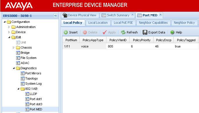
158 157
159 Verify Operations Assuming an IP Phone 1230 IP Phone set is connected to port Verify LLDP-MED Step 1 Verify LLDP neighbor details by using the following command: ERS-Stackable#show lldp port 5 neighbor detail Result: lldp neighbor Port: 5 Index: 4 Time: 3 days, 19:18:15 ChassisId: Network address IPv PortId: MAC address 00:24:00:0d:8d:aa SysCap: TB / TB (Supported/Enabled) PortDesc: Nortel IP Phone SysDescr: Nortel IP Telephone 1230, Firmware:062AC6R PVID: 0 VLAN Name List: 805 PPVID Supported: not supported(0) PPVID Enabled: none Dot3-MAC/PHY Auto-neg: supported/enabled OperMAUtype: 100BaseTXFD PSE MDI power: not supported/disabled Port class: PD PSE power pair: signal/not controllable Power class: 2 LinkAggr: not aggregatable/not aggregated AggrPortID: 0 MaxFrameSize: 1522 PMD auto-neg: 10Base(T, TFD), 100Base(TX, TXFD) MED-Capabilities: CNLDI / CNDI (Supported/Current) MED-Device type: Endpoint Class 3 MED-Application Type: Voice VLAN ID: 805 L2 Priority: 6 DSCP Value: 46 Tagged Vlan, Policy defined Med-Power Type: PD Device Power Source: Unknown Power Priority: High Power Value: 6.0 Watt HWRev: FWRev: 062AC6R SWRev: SerialNumber: ManufName: Nortel-05 ModelName: IP Phone 1230 AssetID: Sys capability: O-Other; R-Repeater; B-Bridge; W-WLAN accesspoint; r-router; T-Telephone; D-DOCSIS cable device; S-Station only. Total neighbors: 1 Med Capabilities-C: N-Network Policy; L-Location Identification; I-Inventory; S-Extended Power via MDI - PSE; D-Extended Power via MDI - PD. 158
160 Step 2 Verify LLDP-MED operations by using the following command: ERS-Stackable#show lldp port 5 neighbor med network-policy Result: lldp neighbor Port: 5 Index: 4 Time: 3 days, 19:18:15 ChassisId: Network address IPv PortId: MAC address 00:24:00:0d:8d:aa SysCap: TB / TB (Supported/Enabled) PortDesc: Nortel IP Phone SysDescr: Nortel IP Telephone 1230, Firmware:062AC6R MED-Application Type: Voice VLAN ID: 805 L2 Priority: 6 DSCP Value: 46 Tagged Vlan, Policy defined Sys capability: O-Other; R-Repeater; B-Bridge; W-WLAN accesspoint; r-router; T-Telephone; D-DOCSIS cable device; S-Station only. Total neighbors: Verify LLDP-MED Policy Configuration Step 1 Verify LLDP neighbor details by using the following command: ERS-Stackable# show lldp med-network-policies voice Result: lldp voice network-policies Port Voice Tagging DSCP Priority VlanID tagged tagged tagged tagged tagged tagged tagged tagged tagged
161 LLDP-MED configuration on the ERS8300 In order to support LLDP-MED Network Policy TLV, ADAC must be enabled on an interface level in addition to enabling at minimum LLDP-MED Capabilities TLV and LLDP-MED Network Policy TLV. Assuming the ERS8300 is configured as a Layer 2 switch with access ports 1/1 to 1/5 for IP phones, enter the following: Enable ADAC at interface level ERS Step 1 Enable ADAC on port members 1/1 to 1/5 PPCLI ERS8300-2:5# config ethernet 1/1-1/5 adac enable CLI ERS8310-1:5(config)#interface fastethernet 1/1-1/5 ERS8310-1:5(config-if)#adac port enable ERS8310-1:5(config-if)#exit 160
162 Enable LLDP-MED ERS Step 1 Enable LLDP VLAN name on port 1/1 to 1/5 PPCLI ERS8300-2:5# config ethernet 1/1-1/5 lldp tx-tlv local-mgmt-addr-tx enable ERS8300-2:5# config ethernet 1/1-1/5 lldp tx-tlv sys-name enable ERS8300-2:5# config ethernet 1/1-1/5 lldp tx-tlv sys-desc enable ERS8300-2:5# config ethernet 1/1-1/5 lldp tx-tlv sys-cap enable ERS8300-2:5# config ethernet 1/1-1/5 lldp tx-tlv port-desc enable ERS8300-2:5# config ethernet 1/1-1/5 lldp tx-tlv med network-policy enable ERS8300-2:5# config ethernet 1/1-1/5 lldp tx-tlv med extendedpse enable ERS8300-2:5# config ethernet 1/1-1/5 lldp tx-tlv med capabilities enable CLI ERS8310-1:5(config)#interface fastethernet 1/1-1/5 ERS8310-1:5(config-if)#lldp tx-tlv local-mgmt-addr ERS8310-1:5(config-if)#lldp tx-tlv sys-name sys-desc sys-cap ERS8310-1:5(config-if)#lldp tx-tlv port-desc ERS8310-1:5(config-if)#lldp status txandrx ERS8310-1:5(config-if)#lldp tx-tlv med capabilities extendedpse ERS8310-1:5(config-if)#lldp tx-tlv med network-policy ERS8310-1:5(config-if)#exit 161
163 af Power over Ethernet The intention of the 802.3af standard is to provide a 10BaseT, 100BaseT, or1000baset device with a single interface for the data it requires and the power to process the data. Power is supplied by a Power Sourcing Device (PSE) for one or more Powered Devices (PD). The PSE main function is to only supply power for a PD after it has successfully detected a PD on a link by probing. The PSE can also successfully detect a PD, but then opt to not supply power to the detected PD. The PSE shall only supply power on the same pair as those used for detection. The cable requirements are defined in ISO/IEC and EIA/TIA 568A/B (T-568A or B, with most using the A standard) which allows for up to 100 meters of cable. Power Sourcing Devices (PSE) can deliver power on the data pairs (1+2, 3+6), spare pairs (4+5, 7+8), or either, but only on the pair that the Powered Device (PD) is detected on. Power is not to be supplied to non-powered devices and other PSE s. T-568B T-568A O/ 0 G/ B B/ G Br/ Br G/ G O/ B B/ O Br/ Br Figure 16: PD and PSE 8-pin Modular Jack Pin s Conductor Alternative A (MDI-X) Alternative A (MDI) Alternative B (All) 1 Negative V Port Positive V Port 2 Negative V Port Positive V Port 3 Positive V Port Negative V Port 4 Positive V Port 5 Positive V Port 6 Positive V Port Negative V Port 7 Negative V Port 8 Negative V Port Table 12: PSE Pinout Alternative In regards to the PD, it must fall into the following characteristics: 19k to 26.5k ohm DC resistance <100nF of capacitance and a voltage offset of at least 2VDC in the signature characteristics a current of less than 12uA in the signature characteristics Anything outside of the characteristics listed above will be considered a non-pd device and the PSE will not supply power. Each port from a PSE should be capable of delivering up to 15.4W of power af also adds a class feature that allows the PSE to limit the power based on the class of the PD detected. Table 13 shown below lists the 802.3af power classes. 162
164 Class Usage Range of MAXIMUM power used by the PD 0 Default 0.44 to Watts 1 Optional 0.44 to 3.84 Watts 2 Optional 3.84 to 6.49 Watts 3 Optional 6.49 to Watts 4 Not Allowed Reserved for Future Use Table 13: 802.3af PD Power Classification 5.1 IP Deskphone Power Requirements Table 14 displays the average power consumed for each Avaya IP Phone set. Model Product Code PoE Class Typical use Power (Watts) 2007 All All E NTYS03xA NTYS03xCE Minimum Software 1120E NTYS03xDE UNISTIm 3.1 / SIP E NTYS03xEE6, NTYS03xFE UNISTim 3.4 / SIP E NTYS05xA NTYS05xCE E NTYS05xCE6 Rel 50 & higher UNISTIm 3.1 / SIP E NTYS05xEE6, NTYS05xFE UNISTim 3.4 / SIP E NTYS06xxE E NTYS07xxE All All All I All SW-I All I All I All w/bm32 All All G All L All C All G All G All All G All G All All C All G All Table 14: IP Deskphone Power Requirements 163


165 5.2 Avaya PoE Switches Ethernet Routing Switch 8300 This chassis system provides both 10/100 and 10/100/ port I/O modules capable of PoE. When utilizing PoE, make sure to engineer the power requirements of the chassis properly. The amount of PoE per module is configurable up to 800 watts per module, along with the ability to specify port priority for PoE. The total PoE power required will dictate the type of input power for the chassis. The ERS 8300 provides different power options as indicated in Table 15. ERS 8300 Six Slot Chassis Power Supply 8301AC 8302AC Power Supply Rating VAC 20 Amp 1140 watts VAC 20 Amp 1770 watts VAC 15 Amp 850 watts VAC 15 Amp 1400 watts ERS 8300 Ten Slot Chassis # of Power Supplies Redundancy PoE Available 1 No 400 watts 2 Yes watts 3 Yes watts 1 No 800 watts 2 Yes watts 3 Yes watts 1 No 200 watts 2 Yes watts 3 Yes watts 1 No 400 watts 2 Yes watts 3 Yes watts Table 15: ERS 8300 Power over Ethernet Options 164
166 Ethernet Routing Switch 5600 The PoE capable ERS 5600 series stackable switches are available in a 48-port and a 96-port version. The ERS 5600 offers built-in, hot swappable redundant power supply options in both AC and DC varieties. It is also capable of providing full 15.4watts per port on every port in the switch along with full N+1 redundant power simultaneously. The available configurations for power options are specified in Table 16. ERS 5650TD-PWR ERS 5698TFD-PWR Switch Model PoE with one PoE with two power supply power supplies ERS 5650TD-PWR (600W) 370 watts total 740 watts total 7.7 watts/port 15.4 watts/port ERS 5650TD-PWR 740 watts total 740 watts total * (1000W) 15.4 watts/port 15.4 watts/port ERS 5698TFD-PWR 740 watts total 1480 watts total (1000W) 7.7 watts/port 15.4 watts/port * Full 15.4 watts on every port with N+1 power redundancy PoE with three power supplies N/A N/A 1480 watts total * 15.4 watts/port Table 16: ERS 5600 Power over Ethernet Options Ethernet Routing Switch 5500 The PoE capable ERS 5520 stackable switch is available in both a 24-port and a 48-port version. The ERS 5520 provides up to 320 watts per switch on standard 110/240 VAC power. To provide more power and/or redundant power, use the ERS Redundant Power Supply 15 (RPS 15) to augment the ERS The RPS 15 can support up to three ERS 5520 switches. The available configurations for power options are specified in Table 17. ERS T-PWR ERS-24T-PWR Switch Model ERS ERS-24T- PWR ERS T- PWR PoE on Standard AC 320 watts total 13.3 watts/port 320 watts total 6.7 watts/port RPS 15 Power Sharing 740 watts total 15.4 watts/port 740 watts total 15.4 watts/port RPS 15 RPSU 320 watts total 13.3 watts/port 320 watts total 6.7 watts/port Table 17: ERS 5500 Power over Ethernet Options 165
 to augment the ERS 4500.")
167 Ethernet Routing Switch 4500 The PoE capable ERS 4500 stackable switches are available in 10/100 and 10/100/ port versions. The ERS 4500 provides up to 370 watts per switch on standard 110/240 VAC power. To provide more power and/or redundant power, use the ERS Redundant Power Supply 15 (RPS 15) to augment the ERS The RPS 15 can support up to three ERS 4500 switches. The available configurations for power options are specified in Table 18. ERS 4526T-PWR ERS 4550T-PWR ERS 4524GT-PWR ERS 4548GT-PWR ERS 4526GTX-PWR Switch Model PoE on Standard RPS 15 Power AC Sharing RPS 15 RPSU ERS 4526T-PWR 370 watts total 15.4 watts/port 740 watts total 15.4 watts/port 370 watts total 15.4 watts/port ERS 4550T-PWR 370 watts total 7.7 watts/port 740 watts total 15.4 watts/port 370 watts total 7.7 watts/port ERS 4524GT- PWR 360 watts total 15.0 watts/port 740 watts total 15.4 watts/port 360 watts total 15.0 watts/port ERS 4548GT- PWR 320 watts total 6.7 watts/port 740 watts total 15.4 watts/port 320 watts total 6.7 watts/port ERS 4526GTX- PWR 360 watts total 15.0 watts/port 740 watts total 15.4 watts/port 360 watts total 15.0 watts/port Table 18: ERS 4500 Power over Ethernet Options 166
168 Ethernet Routing Switch 2500 The PoE capable ERS 2500 switches are available in both a 24-port and a 48-port version. With both of these ERS 2500 switches, PoE is provided on half the ports (ports 1-12 of the 24 port switch and ports 1-24 on the 48 port switch). The ERS 2500 provides up to 165 watts per switch on standard 110/240 VAC power. The ERS 2500 does not support a redundant power option. The available configurations for power options are specified in Table 19. ERS 2526T-PWR ERS 2550T-PWR Switch Model PoE on Standard RPS 15 Power AC Sharing RPS 15 RPSU ERS 2526T-PWR 165 watts N/A N/A ERS 2550T-PWR 165 watts N/A N/A Table 19: ERS 2500 Power over Ethernet Options 167
169 Redundant Power Supply 15 (RPS 15) The RPS 15 provides redundant power to the Avaya stackable Ethernet switches (both PoE and non-poe). The RPS 15 is comprised of the following components: RPS 15 Chassis (supports up to three 600 watt power supplies) 600 Watt Power Supply DC-DC Converter (only required for some switches see table below) DC cable to connect power supply to Ethernet switch The RPS 15 supports two different DC cable types. The first (AA ) is used with all Ethernet switches that have a built-in DC-DC converter and can provide a single power connection to one Ethernet switch. The second type of cable, which comes in two models (AA and AA ) is used with all Ethernet switches that require the addition of the DC-DC converter module. This second cable type can provide a single power connection for up to four Ethernet switches. The RPS 15 can be added to an Ethernet switch or stack of Ethernet switches while the switches are powered up and running. There is no need to power off the switch to connect the RPS 15 cable. ERS 5520 DC Cable AA ERS 5520 ERS 5510 ERS 5510 ERS 5510 ERS 5510 RPS 15 with Three 600w Power Supplies DC Cable AA (25 ) Or DC Cable AA (10 ) Figure 17: Redundant Power Supply 15 (RPS15) 168
170 Table 20 provides information on the required components when using the RPS 15 with the various Ethernet switching options. Switch Model PoE Capable Switch RPS 15 Chassis RPS w Power Supply DC-DC Converter DC Cable for Built-In Converter 10 or 25 DC Cable ERS 5510 No 1 1 per 4 switches Required N/A Required ERS 5520 Yes 1 1 Built-In Required N/A ERS 5530 No 1 1 Built-In Required N/A ERS 4526FX No 1 1 per 4 switches Required N/A Required ERS 4526T No 1 1 per 4 switches Required N/A Required ERS 4526T-PWR Yes 1 1 Built-In Required N/A ERS 4550T No 1 1 per 4 switches Required N/A Required ERS 4550T-PWR Yes 1 1 Built-In Required N/A ERS 4524GT No 1 1 per 4 switches Required N/A Required ERS 4524GT-PWR Yes 1 1 Built-In Required N/A ERS 4548GT No 1 1 per 4 switches Required N/A Required ERS 4548GT-PWR Yes 1 1 Built-In Required N/A ERS 4526GTX No 1 1 per 4 switches Required N/A Required ERS 4526GTX- PWR Yes 1 1 Built-In Required N/A ES T-PWR Yes 1 1 Built-In Required N/A ES T-PWR Yes 1 1 Built-In Required N/A ES T No 1 1 per 4 switches Required N/A Required ES T No 1 1 per 4 switches Required N/A Required Table 20: RPS 15 Configuration Options 169
171 5.3 Configuring PoE Stackable Ethernet Routing Switch By default, PoE Power Management is enabled by default with all PoE ports power enabled at power up. The following commands apply to the switches listed in the previous section Displaying PoE Status and Statistics and setting global settings To display the PoE status and statistics, you can use the following commands: To view the Global PoE status, enter the following command: ERS-Stackable(config)#show poe-main-status ERS-Stackable(config)#show poe-main-status unit <1-8> To view the PoE port status, enter the following command: ERS-Stackable(config)#show poe-port-status ERS-Stackable(config)#show poe-port-status <port unit/port> To view power used on a PoE port, enter the following command: ERS-Stackable(config)#show poe-power-measurement ERS-Stackable(config)#show poe-power-measurement <port unit/port> To change the trap threshold, enter the following commands: ERS-Stackable(config)#poe poe-power-usage-threshold <1-99> ERS-Stackable(config)#poe poe-power-usage-threshold unit <1-8> <1-99> To set the PD detection type, enter the following command: ERS-Stackable(config)# poe poe-pd-detect-type <802dot3af 802dot3ad_and_legacy> ERS-Stackable(config)# poe poe-pd-detect-type unit <1-8> <802dot3af 802dot3ad_and_legacy> 170


172 EDM: To view or configure the PoE global status, enter the following: Using EDM, go to the Device Physical View, right-click the switch and select Edit Go to the PoE tab To view or configure the PoE port status, enter the following: Using EDM, go to the Device Physical View, right-click the port or ports and select Edit Go to the PoE tab 171
173 PoE Settings CLI By default, all ports support 802.3af Power Class of 0 providing up to 15.4W per port. To disable PoE at a port level, enter the following commands: ERS-Stackable(config)#interface fastethernet all ERS-Stackable(config-if)#poe poe-shutdown port <port #> ERS-Stackable(config-if)#exit To configure the PoE power level, enter the following commands where the value <3-16> is the power limit in watts: ERS-Stackable(config)#interface fastethernet all ERS-Stackable(config-if)#poe poe-limit port <port #> <3-16> ERS-Stackable(config-if)#exit To set the PoE port priority, enter the following commands: ERS-Stackable(config)#interface fastethernet all ERS-Stackable(config-if)#poe poe-priority port <port #> <low high critical> ERS-Stackable(config-if)#exit 172

174 EDM: To disable PoE on a port via EDM, perform the following: Go to the Device Phyical View Right-click on the port and select Edit o If you wish to configure multiple port, press the Ctrl key and left click each port you wish to configure Go to the PoE tab 173
175 5.3.2 Ethernet Routing Switch 8300 By default, PoE Power Management is enabled with all PoE ports power enabled at power up Displaying PoE Status and Statistics To display the PoE status and statistics, you can use the following commands: To view the Global PoE status per module, enter the following command: PPCLI ERS-8310:5# show poe card info CLI ERS-8310:5#show poe main-status To view the PoE port status, enter the following command: PPCLI ERS-8310:5# show poe port info CLI ERS-8310:5#show To view the PoE port stats, enter the following command: PPCLI ERS-8310:5# show poe port stats CLI ERS-8310:5#show poe port-status To view power used on a PoE port, enter the following command: PPCLI ERS-8310:5# show poe port power-measurement <slot/port> CLI ERS-8310:5#show poe port-stats To view the PoE system status, enter the following command: PPCLI ERS-8310:5# show poe sys info CLI ERS-8310:5#show poe sys-status 174
176 JDM - Port Level Right-click on the port> Edit>PoE o If you wish to configure multiple ports, press the Ctrl key and left click each port you wish to configure PoE Statistics per port 175
177 PoE Settings To disable PoE on a port, enter the following command: PPCLI ERS-8310:5# config poe port <slot/port> admin disable CLI ERS-8310:5(config)#interface fastethernet <slot/port> ERS-8310:5(config-if)#poe shutdown ERS-8310:5(config-if)#exit To disable PoE on a slot basis, enter the following command: PPCLI ERS-8310:5# config poe card <slot #> admin disable CLI ERS-8310:5(config)# poe shutdown slot <slot #> To limit PoE power at a port level, enter the following command: PPCLI ERS-8310:5# config poe port <slot/port> power-limit <3-16> CLI ERS-8310:5(config)#interface fastethernet <slot/port> ERS-8310:5(config-if)# poe limit <3-16> ERS-8310:5(config-if)#exit To limit PoE power at a module level from 37 to 800W, enter the following command: PPCLI ERS-8310:5# config poe card 1 power-limit <slot #> <37-800> CLI ERS-8310:5(config)#poe limit slot <slot #> <37-800> To set the PoE slot priority, enter the following command: PPCLI ERS-8310:5# config poe card <card #> power-priority <low high critical> CLI ERS-8310:5(config)#poe priority slot <slot #> <low high critical> To set the PoE priority at a port level, enter the following command: 176
178 PPCLI ERS-8310:5# config poe port <slot/port> power-priority <low high critical> CLI ERS-8310:5(config)#interface fastethernet <slot/port> ERS-8310:5(config-if)#poe priority <low high critical> ERS-8310:5(config-if)#exit To set the PoE detection control, enter the following command. The PSE Power Management Admin Status is enabled by default with power detection set on all ports to auto mode. Power detection can be set for either auto or test where test mode implies the port is in continuous discovery without supplying power. Under normal operation, the Ethernet Routing Switch 8300 will not supply power unless a PD (Powered Device) is requesting power. To change the detection control, enter the following commands. PPCLI ERS-8310:5# config poe port <slot/port> power-detection-control <auto test> CLI ERS-8310:5(config)#interface fastethernet <slot/port> ERS-8310:5(config-if)#poe detect-control <auto test> ERS-8310:5(config-if)#exit To set the Power Device (PD) Type, enter the following command: PPCLI ERS-8310:5# config poe port 1/1 type <other telephone webcam wireless> CLI ERS-8310:5(config)#interface fastethernet <slot/port> ERS-8310:5(config-if)# poe type <other telephone webcam wireless> ERS-8310:5(config-if)#exit To set the PoE Trap Threshold, enter the following command: PPCLI ERS-8310:5# config poe card <slot #> power-usage-threshold <0-99> CLI ERS-8310:5(config)# poe usage-threshold slot <slot #> <0-99> 177
179 To disable PoE threshold notification, enter the following command: PPCLI ERS-8310:5# config poe card notification-control <enable disable> CLI ERS-8310:5(config)# no poe notification slot <slot#> 178


180 JDM Port Level: Right-click on the port> Edit>PoE If you wish to configure multiple ports, press the Ctrl key and left click each port you wish to configure Enable/disable PoE power per port JDM Card Level: Select slot that you wish to configure, it should be high-lighted in a yellow box Right-click the card and select Edit>PoE Enable/disable PoE power per slot 179
181 6. Avaya Enery Saver You can use Avaya Energy Saver (AES) to reduce network infrastructure power consumption without impacting network connectivity. AES uses intelligent switching capacity reduction in offpeak mode to reduce direct power consumption by up to 40%. AES can also use Power over Ethernet (PoE) port power priority levels to shut down low priority PoE ports and provide more power savings. The power consumption savings of each switch is determined by the number of ports with AES enabled and by the power consumption of PoE ports that are powered off. If AES for a port is set to disabled, the port is not powered off, irrespective of the PoE configuration. AES turns off the power to a port only when PoE is enabled globally, the port has AES is enabled, and the PoE priority for the port is configured to low. You can schedule AES to enter lower power states during specified periods of time. These time periods can be a complete week, complete weekend, or individual days. Because AES reduces the port speed to 10 Mbps full duplex when AES is activated, the IP phone will experience a short loss of traffic. Depending on the Avaya IP Phone model, this loss can be anywhere from 3 to 15 seconds as shown in the following chart. Avaya IP Phone Duration of loss of traffic Setup 1600, 4600, 9600 Series 3-5 seconds Using double DHCP 3-5 seconds LLDP-MED with Network Policy 25 seconds ADAC with LLDP-MED 1100, 1200, 2000 Series 5-15 seconds Using double DHCP 8-13 seconds LLDP-MED with Network Policy 70 seconds ADAC with LLDP-MED The Avaya 1600, 4600, and 9600 series are faster to recover when AES is activiated as they cache the VLAN and IP address. The 1100, 1200, and 2000 series will always perform a DHCP request when AES is activated even if the cached IP setting is enabled this setting is only used when the IP Phone cannot reach the DHCP server. 180
182 7. QoS 7.1 Interface Roles Stackable Ethernet Routing Switch The Ethernet Routing Switch ports are classified into one of three categories which are trusted, untrusted, or unrestricted. The classifications of trusted, untrusted, and unrestricted actually apply to groups of ports (interface groups). These three categories are also referred to as interface classes. In your network, trusted ports are usually connected to the core of the DiffServ network, and untrusted ports are typically access links that are connected to end stations. Unrestricted ports can be either access links or connected to the core network. At factory default, all ports are considered untrusted. However, for those interface groups created, the default is unrestricted. Because a port can belong to only one interface group, a port is classified as trusted, untrusted, or unrestricted. These types are also referred to as interface classes. The default processing of trusted and untrusted interfaces is as follows: Trusted interfaces IPv4 traffic received on trusted interfaces is re-marked at the layer 2 level, that is, the 802.1p user priority value is updated based on the DSCP value in the packet at ingress and the installed DSCP-to-CoS mapping data. The DSCP value is not updated. On the 5500 Series switch, remapping occurs, by default, only for standardized DSCP values (for example, EF, AFXX) and any proprietary Nortel values. On the 5600 Series switch, remapping occurs for all DSCP values. The DSCP values that are remapped are associated with a zero 802.1p user priority value in the DSCP-to-COS Mapping Table. The 5600 Series switch uses a hardware based DSCP table to support Trusted processing. No policies or filters are consumed by the 5600 Series. Untrusted interfaces IPv4 traffic received on untrusted interfaces is re-marked at the layer 3 level that is, the DSCP value is updated. The new DSCP value is determined differently depending on whether the packet is untagged or tagged: o o Untagged frames The DSCP value is derived using the default port priority of the interface receiving the ingressing packet. This default port priority is used to perform a lookup in the installed CoS-to-DSCP mapping table. The 802.1p user priority value is unchanged that is, the default port priority determines this value. (Thus, the DSCP value on untagged frames on untrusted interfaces is updated using the default port priority of the ingress interface; the user sets the default port priority). Tagged frames The DSCP value is re-marked to indicate best-effort treatment is all that is required for this traffic. The 802.1p user priority value is updated based on the DSCP-to-CoS mapping data associated with the best effort DSCP, which is
183 Table 21 "Default QoS fields by class of interface IPv4 only" shows the default guidelines the switch uses to re-mark various fields of IPv4 traffic (and layer 2 traffic matching IPv4) based on the class of the interface. These actions occur if the user does not intervene at all; they are the default actions of the switch. Action Trusted Untrusted Unrestricted DSCP Does not change Tagged--Updates to 0 (Standard) Untagged--Updates using mapping table and port s default QoS level value Does not change IEEE 802.1p Updates based on DSCP mapping table value Updates based on DSCP mapping table value Tagged Updates to 0 Untagged--Updates to port s default value Does not change Table 21: Default QoS fields by class of interface IPv4 only By default, all ports are untrusted using the default role combination named allqospolicyifcs. This can be viewed by using the following command: ERS-Stackable#show qos if-group Role Interface Capabilities Storage Combination Class Type allqospolicyifcs Untrusted Input 802, Input IP ReadOnly $remediationifcs Unrestricted Input 802, Input IP Other $NsnaIfcs Unrestricted Input 802, Input IP Other The following demonstrates several methods used to configure a simple layer 2 filter depending on if the ports are configured as untrusted or trusted. In our example VLAN 220 will be used for the Voice VLAN and VLAN 1000 as the data VLAN. 7.2 Default QoS Operations - ERS 8300 In regards to the ERS 8300, by default, both the DSCP and p-bit values are passed as-is. The p- bit value determines the QoS level. If you wish to use the DSCP value instead of the p-bit value to determine the QoS level, the port parameter trust-dscp should be enabled (in software versions prior to and on I/O modules other than the 8348GTX or 8348GTX-PWR, an ACL must be configured to trust DSCP instead). 182
184 7.3 QoS Mapping Table 22 display s the default QoS Avaya service class mapping. This is the default mapping used with all the Avaya switches mentioned in the TCG. DSCP TOS Binary Decimal NNSC PHB DSCP/ToS 0x0 0x Standard CS0 0x0 0x DE 0x8 0x /32 Bronze CS1 0xA 0x /40 AF11 0x10 0x /64 Silver CS2 0x12 0x /72 AF21 0x18 0x /96 Gold CS3 0x1A 0x /104 AF31 0x20 0x /128 Platinum CS4 0x22 0x /136 AF41 0x28 0xA /160 Premium CS5 0x2E 0xB /184 EF 0x30 0xC /192 Network CS6 0x38 0xE /224 Critical CS7 Table 22: Avaya QoS Class Mappings 183
185 7.4 Queue Sets Ethernet Routing Switch 2500 The ERS 2500 has four hardware queues which can be viewed by using the following CLI command. The first queue, strict priority, is always serviced first. The remaining three queues are serviced using a weighted-round-robin (WRR) scheduler. 2526T-PWR#show qos queue-set Set Queue General Bandwidth Absolute Bandwidth Service Size ID ID Discipline (%) Bandwidth Allocation Order (Bytes) (Kbps) 4 1 Priority Queuing Relative Weighted Round Robin 65 0 Relative Weighted Round Robin 26 0 Relative Weighted Round Robin 9 0 Relative The default priority mapping can be used by the issuing the following CLI command. 2526T-PWR#show qos queue-set-assignment Queue Set p Priority Queue The default DSCP to priority mapping can be viewed by issuing the following command. 2526T-PWR#show qos egressmap status DSCP 802.1p Priority Drop Precedence Name 0 0 High Drop Standard Service 1 0 High Drop Standard Service 2 0 High Drop Standard Service 3 0 High Drop Standard Service 8 2 High Drop Bronze Service [ ] 16 3 High Drop Silver Service [ ] 24 4 High Drop Gold Service [ ] 32 5 High Drop Platinum Service [ ] 40 6 Low Drop Premium Service [ ] 48 7 Low Drop Network Service [ ] 56 7 Low Drop Critical Service [ ] 63 0 High Drop Standard Service 184
186 7.4.2 Ethernet Routing Switch 4500 Beginning with release 5.4, the ERS 4500 now supports up to 8 different queue sets with a buffering sharing setting, and support for egress traffic shaping. Depending on the queue set, up to eight queues are supported. The default settings include queue-set 2 supporting two strict queues with and a buffer sharing setting of Large. Egress CoS Queuing CLI Commands 4500-PWR(config)#qos agent queue set <1-8> 4500-PWR#show qos queue-set 4500-PWR#show qos queue-set <1-8> 4500-PWR(config)#default qos agent queue-set The qos agent queue set <1-8> command sets the egress CoS and QoS queue mode (1-8) in which the switch will operate. This parameter is global and requires a reset to activate a change. Please note, although up to 32 queue sets shown using the show qos queue-set, you can only select one of the first eight queue sets. The show qos queue-set command displays the queue set configuration. The display includes the general discipline of the queue, the percent bandwidth (Kbps), and the queues size in bytes. The default qos agent queue-set command will default the egress CoS and QoS queue set back to queue mode is PWR(config)# qos agent buffer <large maximum regular> 4500-PWR(config)#show qos agent 4500-PWR(config)#qos agent reset-default The qos agent buffer <regular large maximum > command allows the user to specify the level of resource sharing on the switch. This parameter is global and requires a reset to activate a change. The show qos agent command displays the current attributes for egress CoS and QoS queue mode, resource sharing mode, and QoS NVRAM commit delay. The qos agent reset-default command resets QoS to its configuration default PWR(config)#qos queue-set-assignment queue-set <1-32> 1p <0-7> queue <1-8> 4500-PWR#show qos queue-set-assignment 4500-PWR#show qos queue-set-assignment queue-set <1-32> The qos queue-set-assignment queue-set <1-32> 1p <0-7> queue <1-8> command gives the user the ability to specify the queue to associate an 802.1p priority. The show qos queue-set-assignment command displays in the CLI the 802.1p priority to egress CoS and QoS queue mapping for CoS setting. 185
187 4500-PWR(config)#qos egressmap [name <policy-name>] ds <DSCP-value 0-63> 1p <802.1P-value 0-7> dp <drop-precedence low-drop high-drop> newds <mutated- DSCP-value 0-63> QoS DSCP mutation is a QoS feature (release 5.4 or higher) which extends the trusted interface support to allow recolouring of the DSCP values on egress utilising the mapping tables rather than filters. This feature enables the switch to not only set the Class of Service, but to also recolour the DSCP value on egress without using any filter resouces. In software releases prior to v5.4 the ERS4500 supported one queue set, queue set 4, made up of four queues with maximum allocation. QoS Egress Queue Traffic Shaping 4500-PWR(config)# qos if-queue-shaper port <port> queue <1-8> shape-rate < > shape-min-rate < > 4500-PWR(config)#show qos if-queue-shaper port <port> {queue <1-8>} Egress Queue Shaping allows the ability to configure egress shaping on either a per port basis or on a per Class-of-Service basis on the ERS Can be applied to any of the 8 egress queues per port Provides shaping granularity of 1Mbps or 64kbps 186
188 QoS Guidelines QoS resources are shared on the Ethernet Routing Switch 4500 across groups of ports. Each hardware device (ASIC) contains 24 to 26 ports as per table 23 below and supports the following scaling: Up to 128 classifiers for each mask precedence for each ASIC. Up to 64 meters for each mask precedence for each ASIC. Up to 64 counters for each mask precedence for each ASIC. Up to 8 precedence masks for each port. Up to 16 range checkers for each ASIC. Model ASIC Device 1 ASIC Device FX, 4526T, 4526T- PWR, 4526GTX, Port 1-24 or 26 Not Applicable 4526GTX-PWR 4550T, 4550T-PWR, 4548GT, 4548GT-PWR Port 1-24 Port or 50 Table 23: Ethernet Routing Switch 4500 ASIC The QoS resources used can be viewed by using the following command: 4500-PWR#show qos diag unit <1-8> A maximum of 16 port ranges are supported for each hardware device (ASIC). 187
189 7.4.3 Ethernet Routing Switch 5000 The ERS 5000 supports up to 8 different queue sets, a buffering sharing setting, and support for egress traffic shaping. Depending on the queue set, up to eight queues are supported. The default settings include queue-set 2 supporting two strict queues with and a buffer sharing setting of Large. Egress CoS Queuing CLI Commands 5000-PWR(config)#qos agent queue set <1-8> 5000-PWR#show qos queue-set 5000-PWR#show qos queue-set <1-8> 5000-PWR(config)#default qos agent queue-set The qos agent queue set <1-8> command sets the egress CoS and QoS queue mode (1-8) in which the switch will operate. This parameter is global and requires a reset to activate a change. Please note, although up to 56 queue sets shown using the show qos queue-set, you can only select one of the first eight queue sets. The show qos queue-set command displays the queue set configuration. The display includes the general discipline of the queue, the percent bandwidth (Kbps), and the queues size in bytes. The default qos agent queue-set command will default the egress CoS and QoS queue set back to queue mode is PWR(config)# qos agent buffer <large lossless maximum regular> 5520-PWR(config)# qos agent buffer <large maximum regular> 5000-PWR(config)#show qos agent 5000-PWR(config)#qos agent reset-default The qos agent buffer <large lossless maximum regular> command allows the user to specify the level of resource sharing on the switch. The lossless value, added in release 6.2, shapes traffic to be lossless at the expense of throughput using 802.3x flow control. In order for lossless to work, the end stations must be capable of sending and responding to 802.3x pause frames. Please note the value of lossless applies only to the ERS 5600 series, hence, it should be used in hybrid stack of ERS 5600 and ERS 5500 switches. This parameter is global and requires a reset to activate a change. The show qos agent command displays the current attributes for egress CoS and QoS queue mode, resource sharing mode, and QoS NVRAM commit delay. The qos agent reset-default command resets QoS to its configuration default PWR(config)#qos queue-set-assignment queue-set <1-56> 1p <0-7> queue <1-8> 4500-PWR#show qos queue-set-assignment 4500-PWR#show qos queue-set-assignment queue-set <1-56> The qos queue-set-assignment queue-set <1-56> 1p <0-7> queue <1-8> command gives the user the ability to specify the queue to associate an 802.1p priority. 188
190 The show qos queue-set-assignment command displays the 802.1p priority to egress CoS and QoS queue mapping for CoS setting PWR(config)#qos egressmap [name <policy-name>] ds <DSCP-value 0-63> 1p <802.1P-value 0-7> dp <drop-precedence low-drop high-drop> newds <mutated- DSCP-value 0-63> QoS DSCP mutation is a QoS feature (release 6.2 or higher) which extends the trusted interface support to allow recoloring of the DSCP values on egress utilising the mapping tables rather than filters. This feature enables the switch to not only set the Class of Service, but to also recolour the DSCP value on egress without using any filter resouces. QoS Egress Queue Traffic Shaping 5000-PWR(config)# qos if-queue-shaper port <port> queue <1-8> shape-rate < > shape-min-rate < > 5000-PWR(config)#show qos if-queue-shaper port <port> {queue <1-8>} Egress Queue Shaping allows the ability to configure egress shaping on either a per port basis or on a per Class-of-Service basis on the ERS Can be applied to any of the 8 egress queues per port Provides shaping granularity of 1Mbps or 64kbps 189
191 7.4.4 Ethernet Routing Switch 8300 Each Ethernet port on the Ethernet Routing Switch 8300 supports eight hardware queues as shown in the Table below. Each of the eight queues is mapped to one of the eight QoS levels while each queue can be configured using one of three scheduling arbitration groups, i.e. strict priority, DWRR0, and DWRR1 where strict always have the highest precedence followed by DWRR1 and then DWRR0. This allows you to have the flexibility, if you wish to change all eight queues to Strict Priority. In addition, each per queue shaping can be enabled for shaping with a minimum shaping rate of 1 Mbps Queue Traffic Class Queue 1 7 Drop Precedence Scheduling Group DWRR Weight Size (8348TX) Size (8324GTX) Size (8348GTX) Size (8393SF) Low Strict Priority N/A (highest) 2 6 Low DWRR Low DWRR Low DWRR Low DWRR Low DWRR Low DWRR (lowest) Queue Traffic Class Queue Low DWRR Drop Precedence Scheduling Group DWRR Weight Size (8394SF) 1 7 Low Strict Priority N/A 192 (highest) 2 6 Low DWRR Low DWRR Low DWRR Low DWRR Low DWRR Low DWRR (lowest) Low DWRR Size (8308XPF) Table 24: Ethernet Routing Switch 8300 Egress Queue 190
192 Egress TX Queue CLI Commands Use the following command to change the Tx Queue settings: PPCLI ERS-8310:5# config ethernet <slot/port> tx-queue <0-7> [transmit <value>] [size <value>] [scheduler <value>] [weight <value>] [shaper <value>] [rate <value>] [burst-size <value>] To disable a queue ERS-8310:5# config ethernet <slot/port> tx-queue <0-7> transmit disable CLI ERS-8310:5(config)#interface <fastethernet gigabitethernet> <slot port> ERS-8310:5(config-if)#tx-queue <0-7> transmit [size <value>] [scheduler <value>] [weight <value>] shaper [rate <value>] [burst-size <value>] ERS-8310:5(config-if)#exit To disable a queue ERS-8310:5(config-if)# no tx-queue <0-7> transmit ERS-8310:5(config-if)#exit Where : config ethernet <ports> tx-queue <queue-id> (PPCLI) tx-queue (CLI) followed by: [burst-size <value>] [rate <value>] Sets the shaper burst size in Kilobytes (KB). The default value is 4 KB. The range is an integer value in the range 4 and KB. burst-size <value> allows you to set the shaper burst size in KB. The available range is 1 and KB. Sets the shaping rate in Mb/s. The default value is 10 Mb/s. The range is an integer value in the range 1 and Mb/s. rate <value> allows you to set the shaper maximum rate in Mb/s. The available range is 1 and Mb/s. Note: the actual shaping rate can be different from the configured rate due to the rate granularity of the shaper. 191
193 [scheduler <value>] shaper <value>] (PPCLI only) [size <value>] [transmit <value>] (PPCLI only) [weight <value>] Sets the scheduling Arbitration group. value allows you to set one of the three following scheduling arbitration groups: Strict priority - This Arbitration Group is served first, where the priority goes from the highest queue index to the lowest. DWRR1 - This Arbitration Group may transmit packets when there is no traffic from the SP Arbitration Group. DWRR0 - This Arbitration Group may transmit packets when there is no traffic from the DWRR Group 1. Note: Within each DWRR Arbitration Group, each queue is guaranteed its proportional minimal bandwidth according to its configured weight. Enables or disables transmission of shaper on the port. shaper <value> allows you to enable or disable the feature. Specifies the number of packet descriptors allocated for the queue. size <value> sets the number of descriptors in resolution of 16 { } Enables or disables transmission on the queue. transmit <value> enables or disables the feature Specifies the proportion (in units of 256 bytes) of bandwidth assigned to this queue relative to the other queues in the arbitration group. value is an integer value in the range 1 and 256, which represents units of bandwidth in the DWRR. The default value is 8 units, which is 8 * 256 (2048). Note: Avaya recommends that the minimum weight (N * 256) be greater than the port MTU. 192
194 7.5 Automatic QoS Automatic QoS provides application traffic prioritization allowing for the ability to identify and prioritize Avaya application traffic. This applies to both an Avaya only or Avaya edge and third party core data infrastructure to provide application aware networking. Avaya application traffic is defined as IP Telephony and Multimedia applications. By identifying Avaya application traffic, Automatic QoS transparently provides appropriate traffic prioritization handling and in turn improves application performance particularly in times of network congestion. Automatic QoS is applied end-to-end from the application traffic to the Avaya or third party data infrastructure without the need to configure individual application filters and QoS components across a variety of platforms. Simply enable/disable the appropriate Automatic QoS mode and all underlying QoS configurations to identify Avaya application traffic are automatically configured. Well known Avaya application traffic that is automatically identified via DSCP values will be given preferential treatment and will be handled by the appropriate egress queue on the Ethernet switching infrastructure. As shown in the diagram below, dynamic prioritization is provided by enabling Automatic QoS on the Stackable Ethernet Routing Switch edge access switch and on the CS1000, CS2100, BCM, and/or SRG call servers. In regards to the edge switch, the Stackable Ethernet Routing Switch supports dynamic prioritization for either tagged or untagged IP telephony traffic. The only other configuration required on the edge switch is setting the uplink port members attached to the core/distribution layer as trusted port members. In the core, all that is required is enabling the port members as QoS trusted. Please note that Automatic QoS configuration is only available using the CS1000, CS2100, BCM, and/or SRG call servers. 193
195 7.5.1 Automatic QoS Edge Mode: Stackable Ethernet Routing Switch On the Stackable Ethernet Routing Switch, when enabling dynamic prioritization via Automatic QoS Edge, there are two modes to choose from, mixed mode and pure mode. In mixed mode, the Stackable Ethernet Routing Switch will recognize and remark the traffic from the attached IP phone, IP Softphone 2050 client or BCM/SRG/CS1000/CS2100 according to values shown in Table 25. As long as the switches used in the core/distribution layer are configured as QoS trusted, these remarked DSCP values will be given preferential treatment and will be handled by the appropriate egress queue. NT DSCP from IP Phone Traffic Type Standard DSCP Standard p-bit 0x2F (47) VoIP Data (Premium) 0x2E (46) (EF) 6 0x29 (41) VoIP Signaling 0x28 (40) (CS5) 5 (Platinum) 0x23 (35) Video (Platinum) 0x22 (34) (AF41) 5 0x1B (27) Streaming (Gold) 0x1A (26) (AF31) 4 Table 25: NT DSCP Mapping Values (Mixed) Please note that all other traffic types not identified will be handled as normal unidentified traffic and will be remarked as Standard/Best Effort with DSCP value of 0x00 and treated as untrusted traffic. In pure mode, the Stackable Ethernet Routing Switch will recognize and not remark the traffic from the attached IP phone, IP Softphone 2050 client or BCM/SRG/CS1000/CS2100. Avaya DSCP values will be given preferential treatment and will be handled by the appropriate egress queue and the packet will retain these DSCP values as shown in Table 26. NT DSCP NT p-bit Traffic Type 0x2F (47) 6 VoIP Data (Premium) 0x29 (41) 5 VoIP Signaling (Platinum) 0x23 (35) 5 Video (Platinum) 0x1B (27) 4 Streaming (Gold) Table 26: NT DSCP Values (Pure) Please note that all other traffic types not identified will be handled as normal unidentified traffic and will be remarked as Standard/Best Effort with DSCP value of 0x00 and treated as untrusted traffic. Automatic QoS support is envisioned as a multi-phase project. In phase 1 of Automatic QoS, ADAC, NSNA, Automatic QoS pure mode, or 802.1AB is not supported simultaneously. This will be added in subsequent phases of Automatic QoS. 194
196 7.5.2 Automatic QoS Configuration Stackable Ethernet Routing Switch Automatic QoS is configured by using the following command: where: ERS-Stackable(config)#qos agent aq-mode? Parameter disable mixed pure disable Auto QOS application traffic processing disabled on all ports mixed Auto QOS application traffic processing enabled on all ports with egress DSCP remapping pure Auto QOS application traffic processing enabled on all ports without egress DSCP remapping Description Disables Automatic QoS functionality for the system Enables Automatic QoS functionality with DSCP remarking at egress enabled. Private Avaya DSCP values will be remarked to corresponding standard DSCP values. Enables Automatic QoS functionality with DSCP remarking at egress disabled. Private DSCP values will be honored while all other traffic is remarked to QoS level of Standard. Please note that this mode is not supported at this time. Please note that phase 1 of Automatic QoS does not support ADAC, NSNA, or 802.1AB simultaneously. Depending on the software release, the CLI Automatic QOS command may either be qos agent aq-mode or qos agent nt-mode Core Ports Although not necessary, the core or uplink port members could be configured as QoS trusted ports if you wish to trust all QoS levels besides just the Automatic QoS levels. This can be accomplished by first adding a new QoS interface group and then adding the port members to this interface group. ERS-Stackable(config)#qos if-group name <if-group_name> class trusted ERS-Stackable(config)#qos if-assign port <port members> name <if-group_name> 195
197 7.6 Configuring QoS on a Avaya Switch for Voice Traffic Stackable Ethernet Routing Switch - Creating a new Interface Group of Trusted The following will show how to use a Policy, ACL, or Traffic profile to only trust the voice traffic assuming we will use VLAN 220 for the voice VLAN and 1000 for the data VLAN Section 7.6.1: Creating a new Interface Group with a class of trusted o Remark the data VLAN to CoS level of Standard or best effort by adding either a QoS policy, an ACL, or Traffic Profile Section 7.6.2: Using the default Interface Group with a class of untrusted o Remarking the voice VLAN to CoS level of Premium by adding either a QoS policy, an ACL, or Traffic Profile Stackable Ethernet Routing Switch - Using a Policy ERS Stackable: Step 1 Add a new interface group with a class of trusted and add port members. For this example, we will name the if-group trusted. ERS-Stackable(config)#qos if-group name trusted class trusted ERS-Stackable(config)#qos if-assign port 1-24 name trusted ERS Stackable: Step 2 Create two elements, one matching the voice VLAN and another matching the data VLAN and set the EtherType to 0x0800. An EtherType value of 0x0800 signifies IP traffic ERS-Stackable(config)#qos l2-element 1 vlan-min 220 vlan-max 220 ethertype 0x800 ERS-Stackable(config)#qos l2-element 2 vlan-min 1000 vlan-max 1000 ethertype 0x800 ERS Stackable: Step 3 Add each layer 2 element to a classifier by starting with classifier id 1 and adding the layer 2 element id s from step above ERS-Stackable(config)#qos classifier 1 set-id 1 name voice element-type l2 element-id 1 ERS-Stackable(config)#qos classifier 2 set-id 2 name data element-type l2 element-id 2 196
198 ERS Stackable: Step 3 Create a classifier-block and add both classifiers from the previous step to it. For the voice classifier, we will add an in-profile action of null to pass all voice traffic as-is. For the data classifier, we will add an in-profile action of standard to remark all the traffic to a QoS level of standard. Please note that a classifier block can be used in this example because both of the classifier elements are of the same type, i.e. both are a layer 2 element matching a VLAN with the same EtherType. ERS-Stackable(config)#qos classifier-block 1 block-number 1 name data_remark set-id 1 in-profile-action 9 ERS-Stackable(config)#qos classifier-block 2 block-number 1 name data_remark set-id 2 in-profile-action 2 ERS Stackable: Step 4 Add a policy, for this example named VoIP_Policy, add classifierblock id 1 configured above, and set the precedence to a value from 1 to 7 for the ERS 4500, 2 to 11 for the ERS 2500, and 1 to 15 for the ERS ERS-Stackable(config)#qos policy 1 name "VoIP_Policy" if-group trusted clfrtype block clfr-name data_remark precedence 3 Note that you can use either ID s or names for the classifiers and policy actions. To understand what the in-profile-action and non-match-action refer to, enter the following command: ERS-Stackable #show qos action 2 ERS-Stackable #show qos action 9 Id: 2 Name: Standard_Service Drop: No Update DSCP: 0x p Priority: Priority 0 Set Drop Precedence: High Drop Extension: Session Id: 0 Storage Type: ReadOnly Id: 9 Name: Null_Action Drop: No Update DSCP: Ignore 802.1p Priority: Ignore Set Drop Precedence: Low Drop Extension: Session Id: 0 Storage Type: ReadOnly 197
199 Stackable Ethernet Routing Switch using an ACL ERS Stackable: Step 1 Add a new interface group with a class of trusted and add port members. For this example, we will name the if-group trusted. ERS-Stackable(config)#qos if-group name trusted class trusted ERS-Stackable(config)#qos if-assign port 1-24 name trusted ERS Stackable: Step 1 Create the ACL to match the data VLAN and remark DSCP and p- bit values to 0. Please note the default action of an ACL is drop for all other traffic not matched by an ACL, hence, we also need to add a drop-action of disable to our ACL: ERS-Stackable(config)#qos l2-acl name one vlan-min 1000 vlan-max 1000 ethertype 0x800 drop-action disable update-dscp 0 update-1p 0 ERS-Stackable(config)#qos l2-acl name one ethertype 0x800 drop-action disable ERS Stackable: Step 2 Assign the ACL vlan_fil to the appropriate port members ERS-Stackable(config)#qos acl-assign port 1-24 acl-type l2 name one To view the configuration, enter the following commands ERS-Stackable#show qos l2-acl ERS-Stackable#show qos acl-assign To remove the configuration, enter the following commands: ERS-Stackable#no qos acl-assign x (where x = id assigned to port; in our case, this command has to be repeated 24 times where x = 1 to 24 as we assigned the ACL to 24 port members) ERS-Stackable#no qos l2-acl 1 ERS-Stackable#no qos l2-acl 2 ERS-Stackable#no qos l2-acl all (remove all L2-ACL s) 198
200 Stackable Ethernet Routing Switch using an Traffic Profile Please note Traffic Profiles can only be applied to the ERS 4500 and ERS ERS Stackable: Step 1 Add a new interface group with a class of trusted and add port members. For this example, we will name the if-group trusted. ERS-Stackable(config)#qos if-group name trusted class trusted ERS-Stackable(config)#qos if-assign port 1-24 name trusted ERS Stackable: Step 2 Create the traffic profile to match the data VLAN and remark DSCP and p-bit values to 0 ERS-Stackable(config)#qos traffic-profile classifier name one vlan-min 1000 vlan-max 1000 ethertype 0x800 update-dscp 0 update-1p 0 ERS Stackable: Step 2 Assign the traffic profile one to the appropriate port members ERS-Stackable(config)#qos traffic-profile set port 1-24 name one At mimimum, software release 6.1 for the ERS 5000 and 5.4 for the ERS 4500 must be used in order to create traffic profiles. 199
201 7.6.2 Stackable Ethernet Routing Switch - Assuming default role combination with class of untrusted By default, all ports belong to the default interface group named allqospolicyifcs with an interface class of untrusted. Hence, it is not nessessary to create a new interface group Stackable Ethernet Routing Switch using an Policy ERS Stackable: Step 1 Create a new layer 2 element, assign Voice VLAN and set the EtherType to 0x0800 ERS-Stackable(config)#qos l2-element 1 vlan-min 220 vlan-max 220 ethertype 0x800 ERS Stackable: Step 2 Add layer 2 element to a classifier by starting with classifier id 1 and adding layer 2 element id 1 from step above ERS-Stackable(config)#qos classifier 1 set-id 1 name VoIP_Class element-type l2 element-id 1 ERS Stackable: Step 3 Add a policy, for this example named VoIP_Policy, add classifier id 1 configured above, set in-profile-action to remark to Premium CoS, and set the nonmatch action to remark to Standard CoS. ERS-Stackable(config)#qos policy 1 name VoIP_Policy if-group allqospolicyifcs clfr-type classifier clfr-id 1 in-profile-action 7 non-match-action 2 ERS Stackable: Step 3 Add a policy, for this example named VoIP_Policy, add classifier id 1 configured above, set in-profile-action to remark to Premium CoS, and set the nonmatch action to remark to Standard CoS. ERS-Stackable(config)#qos policy 1 name "VoIP_Policy" if-group allqospolicyifcs clfr-type classifier clfr-id 1 in-profile-action 7 precedence 3 You can also apply the policy to an individual port member instead of an interface role with multiple port members. For example, assuming only wish to apply the policy to port 12, enter the following command: ERS-Stackable(config)#qos policy 1 name VoIP_Policy port 12 clfrtype classifier clfr-id 1 in-profile-action 7 non-match-action 2 200
202 Stackable Ethernet Routing Switch using an ACL ERS Stackable: Step 1 Create an ACL to match the voice VLAN. Please note that default action of an ACL is drop for all other traffic not matched by an ACL, hence, we also need to add a drop-action of disable to our ACL: ERS-Stackable(config)#qos l2-acl name one vlan-min 220 vlan-max 220 ethertype 0x800 update-dscp 46 update-1p 6 ERS-Stackable(config)#qos l2-acl name one ethertype 0x800 drop-action disable ERS Stackable: Step 2 Assign the ACL to the appropriate port members; for example, port member 1-24: ERS-Stackable(config)#qos acl-assign port 1-24 acl-type l2 name one Stackable Ethernet Routing Switch using a Traffic Profile Please note Traffic Profiles can only be applied to the ERS 4500 and ERS ERS Stackable: Step 1 Create the traffic profile to match the voice VLAN and remark DSCP and p-bit values ERS-Stackable(config)#qos traffic-profile classifier name one vlan-min 220 vlan-max 220 ethertype 0x800 update-dscp 46 update-1p 6 ERS Stackable: Step 2 Assign the traffic profile one to the appropriate port members ERS-Stackable(config)#qos traffic-profile set port 1-24 name one At mimimum, software release 6.1 for the ERS 5000 and 5.4 for the ERS 4500 must be used in order to create traffic profiles. 201
203 7.6.3 Configure L2 QoS on a Ethernet Routing Switch 8300 By default, the Ethernet Routing Switch 8300 trusts the 802.1p value with a default behavior as shown in table 27 below. Providing the VoIP VLAN is tagged, no additional configuration steps are required. Traffic Type 802.1p DSCP Behavior Queue Behavior Queue Bridged, i.e. VLAN without IP address Tagged Passed as-is As per traffic Passed as-is As per p-bit class and queue mapping Untagged N/A N/A Passed as-is Queue 1 Routed, i.e. VLAN with IP address assigned Tagged Passed as-is As per traffic Passed as-is As per p-bit class and queue mapping Untagged N/A N/A Passed as-is Queue 1 Table 27: Default QOS Behavior for the Ethernet Routing Switch 8300 If the IP Phone set voice VLAN is not tagged or if the voice VLAN is tagged and you wish to trust the DSCP value instead of the p-bit, you could set up a filter to trust the DSCP value. You can also classify traffic based on VLAN value or filters Trust DSCP Value Configuration To setup a filter to trust the DSCP value, please enter the following commands. ERS8300: Step 1 Create a new ACL with an action to trust the DSCP value. Assuming no ACLs have been configured, start with ACL 1 PPCLI ERS8300:5# config filter acl 1 create ip ERS8300:5# config filter acl 1 ace 1 action permit trust-dscp enable CLI ERS8300:5(config)#filter acl 1 ip ERS8300:5(config)#filter acl 1 action 1 permit trust-dscp enable ERS8300: Step 2 Create an ACG group and add ACL configured in step 1 above. Assuming no ACG have been configured, start with ACG 1 PPCLI ERS8300:5# config filter acg 1 create 1 CLI ERS8300:5(config)#filter acg 1 1 ERS8300: Step 3 Add the ACG created in step 2 to all appropriate port members 202
204 PPCLI ERS8300:5# config ethernet <port #> filter create 1 CLI ERS8300:5(config)#interface fastethernet <slot/port> ERS8300:5(config-if)#filter 1 ERS8300:5(config-if)#exit You can enable or disable trusted DSCP at an interface level as per the configuration steps shown below. ERS8300: Step 1 Enable trust-dscp via interface level PPCLI ERS8300:5# config ethernet <slot/port> qos trust-dscp enable CLI ERS8300:5(config)# interface gigabitethernet <slot/port> ERS8300:5(config-if)#qos trust-dscp enable ERS8300:5(config-if)#exit 203
205 Classify traffic based on VLAN basis For IP subnet and Protocol-based VLANs you can set up a default traffic class level based on the VLAN id. The VLAN QoS level can be assigned a value from 0 (lowest) to 7 (highest) with a default setting of 1. Note that you cannot apply a VLAN QoS level to port-based VLANs. For example, assuming the VoIP VLAN is 220 with port members 1/3 to 1/11, enter the following commands: ERS8300: Step 1 Create VLAN 220 and add port members PPCLI ERS8300:5# config vlan 220 create byprotocol 1 ip ERS8300:5# config vlan 1 ports remove 1/1-1/11 ERS8300:5# config vlan 220 ports add 1/1-1/11 CLI ERS8300:5(config)#vlan create 220 type protocol-ipether2 1 ERS8300:5(config)#vlan members remove 1 1/1-1/11 ERS8300:5(config)#vlan members add 220 1/1-1/11 ERS8300: Step 2 Assign QoS level PPCLI ERS8300:5# config vlan 220 qos-level 6 CLI ERS8300:5(config)#vlan qos-level ERS8300: Step 3 Enable Dynamic MAC QoS Update PPCLI ERS8300:5# config vlan 220 update-dynamic-mac-qos-level enable CLI ERS8300:5(config)#vlan update-dynamic-mac-qos-level 220 The dynamic update parameter is used to enable to disable the update of the MAC traffic class assignment when the VLAN traffic class changes. 204
206 Classify traffic based on a filter Assuming we wish to filter on the VoIP VLAN with the MAC address range belonging to the IP Phone sets and set the DiffServ value to EF (0x2e). This can be accomplished by using the commands shown below. For our example, we will assume the voice VLAN is 220 while the MAC address range is from 00:0a:e4:00:00:00 to 00:0a:e4:ff:ff:ff. PPCLI: ERS8300: Step 1 Create a new ACT to allow ACL filtering on MAC addresses PPCLI ERS8300:5# filter act 2 ethernet ip src-mac ff:ff:ff:ff:ff:ff dst-mac ff:ff:ff:ff:ff:ff vlan-mask 0x0fff name "act_2_ip-mac" CLI ERS8300:5(config)#filter act 2 ethernet ip src-mask ff:ff:ff:ff:ff:ff dst-mask ff:ff:ff:ff:ff:ff vlan-mask 0x0fff name act-2-ip-mac ERS8300: Step 2 Enable the ACT to also allow ACL filtering on the DSCP value PPCLI ERS8300:5# config filter act 2 ip tos 0xff CLI ERS8300:5(config)#filter act 2 ip tos 0xff ERS8300: Step 3 Add ACL 1 using the name ACL-1_VoIP, add ACT 2 created above, and enable the ACL to filter on the specified MAC address in VLAN 220 to remark traffic using Premium CoS and remark all other traffic as Standard CoS PPCLI ERS8300:5# config filter acl 1 create ip acl-name ACL-1_VoIP act-id 2 ERS8300:5# config filter acl 1 ace 1 action permit remark-dscp phbef "ACE- 1_remark" precedence 1 ERS8300:5# config filter acl 1 ace 1 ethernet src-mac 00:0a:e4:00:00:00 range 00:0a:e4:ff:ff:ff vlan-id 220 ERS8300:5# config filter acl 1 ace default action permit remark-dscp phbcs0 CLI ERS8300:5(config)#filter acl 1 ip acl-name ACL-1_VoIP act-id 2 ERS8300:5(config)# filter acl 1 action 1 permit remark-dscp phbef ACE-1_remark precedence 1 ERS8300:5(config)#filter acl 1 ethernet 1 src-mac 00:0a:e4:00:00:00 range 00:0a:e4:ff:ff:ff vlan-id 220 ERS8300:5(config)#filter acl 1 action default permit remark-dscp phbcs0 205
207 ERS8300: Step 4 Create a new ACT to allow ACL filtering on MAC addresses. For this example, we will name the ACG ACG-1_Voip. PPCLI ERS8300:5# config filter acg 1 create 1 acg-name ACG-1_Voip CLI ERS8300:5(config)#filter acg 1 1 acg-name ACG-1_Voip ERS8300: Step 5 Add ACG ACG-1_Voip to interface level and disable p-bit override. PPCLI ERS8300:5# config ethernet <slot/port> filter create 1 ERS8300:5# config ethernet <slot/port> qos 8021p-override enable CLI ERS8300:5(config)#interface fastethernet <slot/port> ERS8300:5(config-if)#filter 1 ERS8300:5(config-if)#qos 8021p-override ERS8300:5(config-if)#exit 206
208 Verify QoS Operation using IPFIX IPFIX can be used to verify the DSCP settings. For example, assuming if we are using an ERS 8000 in the core where the edge switch is connected to port 3/29, entering the following commands on the ERS 8000 allows to verify the DSCP on values send from the traffic ingressing this port. ERS8000: Step 1 Enable IPFIX globally ERS8000:5# config ip ipfix state enable ERS80-00: Step 2 Enable IPFIX at interface level, assuming port 3/29 for this example ERS8000:5# config ip ipfix port 3/29 all-traffic enable ERS8000: Step 3 Verify DSCP values via slot 3, assuming we have VoIP traffic via VLAN 805 ERS8000:5# show ip ipfix flows 3 Results: ================================================================================ IPFIX Flows ================================================================================ Slot Number : 3 Total Number Of Flows : 3 Port/ SrcIP/DstIP Src/ Protcol/ DSCP/ Egrss Start/Last Vlan Addr Dst Obsv TcpFlag Port/ Time Port Point Mgid / udp 184 3/27 AUG 1 11:38: Port none AUG 1 11:38:35 3/ udp 184 3/27 AUG 1 11:38: Port none AUG 13 11:38:36 3/ udp 184 3/3 AUG 1 11:38: Port none AUG 1 11:38:36 Total number of Displayed Flows on Slot 3 : Port/ SrcMac/DstMac Byte/Pkt Vlan Count /29 00:24:00:0d:8d:aa :00:5e:00:01:55 1 3/29 00:24:00:0d:8d:aa :00:5e:00:01: /29 00:24:00:0d:8d:aa :00:5e:00:01: Please note the DSCP value shown is actually the ToS value. To calculate the DSCP value, drop the two least significant binary bits. For this example, 184 in binary is where the two least significant bits become binary or decimal
209 8. Anti-Spoofing Best Practices Overview ARP Poison ARP spoofing simply involves spoofing an IP address of a victim thereby allowing frames destined for the remote host to be forwarded to the attacker. For example, by sending Gratuitous ARP (GARP) frames between an attacker to a victim and a default gateway router within a VLAN of a Layer 2 switch, a man-in-the-middle (MITM) attack can occur. Overview IP Spoofing IP spoofing refers to the creation of IP packets with a spoofed source IP address other than the local network address. By forging the source IP address, an attacker can make the packet appear as it was sent by a different machine. The victim that receives the spoofed packets will send responses back to the forged source address. IP Source Guard IP Source Guard provides security to the network by filtering clients with invalid IP addresses. IPSource Guard works closely with information in the Dynamic Host Control Protocol (DHCP) snooping binding table. When IP Source Guard is enabled on an untrusted port with DHCP snooping enabled, an IP filter entry is created or deleted for that port automatically, based on IP information stored in the corresponding DHCP snooping binding table entry. When a connecting client receives a valid IP address from the DHCP server, a filter is installed on the port to allow traffic only from the assigned IP address. A maximum of 10 IP addresses are allowed on each IP Source Guard-enabled port. When this number is reached, no more filters are set up and traffic is dropped. When IP Source Guard is enabled without DHCP snooping enabled, a default filter is installed and IP traffic for the port is dropped. Defense against Spoofing Avaya IP Phone sets supports GARP feature please see section 3. However, this feature only prevents ARP spoofing one way from the IP Phone set to the default gateway address. Therefore, if the voice call is to another phone set that is off-net (to a phone on a different subnet or switch) an attacker can only poison the phone one-way. The attacker can only record the voice traffic from a remote phone sent to the local phone set and not from the local phone to the remote phone. The IP Phone GARP also does prevent an on-net attack. On-net refers to the same VLAN on a switch where both IP phone are connected. To prevent ARP Spoofing, it is recommended to enabled DHCP Snooping and ARP Spoofing when available on the local switch where the IP Phone sets are connected. Both of these mechanisms will prevent Man-in-the-middle (MITM) attacks and spoofing a victims IP address. In addition, it is also recommended to enable IP Spoofing either on the local switch where the IP Phone sets are attached or in the core. 208
210 Summary Chart The following chart provides a summary of Off-Net and On-Net MITM attacks. An X indicated MITM attack (ARP Spoofing can occur) in both directions, i.e. the ability to capture traffic from a local phone set to the remote phone set and vise-versa. An indicates a MITM attack does not occur An indicates a one-way MITM attack from an remote phone set to the local phone set only Off-Net indicates traffic off the local subnet On-Net indicated traffic between two devices within the same VLAN, i.e. same subnet, on a local switch Switch Traffic Type Off-Net On-Net Generic L2 switch Data X X Voice X X Voice with GARP X X disabled on IP Phone Voice with GARP enabled on IP Phone ERS switch with ARP Data Spoofing Prevention Voice enabled Voice with GARP enabled on IP Phone Table 28: MITM Attacks Support on Avaya Switches Switch Feature DHCP Snooping ARP Inspection IP Source Guard ERS2500 (4.2) (4.2) (4.2) ERS5500 (5.0) (5.0) (5.1) ERS5600 (6.0) (6.0) (6.0) ERS4500 (5.1) (5.1) (5.2) ERS8300 (4.2) (4.2) (4.2) Core ERS8600 (7.0) (7.0) (4.1)* *Requires software release 4.1 with R-modules (does not require R-mode) Table 29: Anti-Spoofing support on Avaya Switches 209

211 9. EAPoL Support 9.1 EAP Overview Extensible Authentication Protocol over LAN is a port-based network access control protocol. EAPoL provides a method for performing authentication at the edge of the network in order to obtain network access based on the IEEE 802.1X standard X specifies a protocol used between devices (EAP Supplicants) that desire access to the network and devices providing access to the network (EAP Authenticator). It also specifies the requirements for the protocol used between the EAP Authenticator and the Authentication server, i.e. RADIUS. The following are some of the 802.1X definitions: Authenticator: The entity that requires the entity on the other end of the link to be authenticated. Authenticator passes authentication exchanges between supplicant and authentication server. Supplicant: The entity being authenticated by the Authenticator and desiring access to the services of the Authenticator. Port Access Entity (PAE): The protocol entity associated with a port. May support functionality of Authenticator, Supplicant or both. Authentication Server: An entity providing authentication service to the Authenticator. May be co-located with Authenticator, but most likely an external server. Figure 18: EAP Overview 210
212 802.1x Ethernet Frame 6 bytes 6 bytes 2 bytes 1 byte 1 byte 2 bytes n bytes Dest. MAC 0180C200000x Source MAC Type 88-8E Protocol Version Packet Type Packet Body Length Packet Body 00 EAP-Packet 01 EAPOL-Start * 02 EAPOL-Logoff * 03 EAPOL-Key 04 EAPOL-Encapsulated-ASF-Alert * No packet body field 1 byte 1 byte 2 bytes n bytes Code Identifier Length Data Packet body field 1 Request 2 Response 3 Success 4 Failure 1 byte 2 bytes 8 bytes 16 bytes Descriptor Type Key Length Relay Counter Key IV 1 byte 16 bytes n bytes Key Index Key Signature Key Packet body field Figure 19: EAP Frame EAP Request and Response Code Types Type code 1: Identity Type code 2: Notification Type code 3: NAK Type code 4: MD-5 Challenge Type code 5: One-time password (OTP) Type code 6: Generic Token Card Type code 13: TLS EAP and RADIUS related RFCs RFC2284 PPP Extensible Authentication Protocol RFC2716 PPP EAP Transport Level Security (TLS) Authentication Protocol RFC2865 (Obsoletes RFC2138) RADIUS RFC2548 Microsoft Vendor specific RADIUS Attributes 211
213 9.2 EAP Support on Avaya IP Phone Sets The following table shows the authentication methods supported on each type of Avaya IP phone. Authentication method EAP MD5 IP Phone IP Phone 2001, IP Phone 2002, IP Phone 2004, IP Audio Conference Phone 2033, IP Phone 1210, IP Phone 1220, IP Phone 1230, IP Phone 2007, IP Phone 1110, IP Phone 1120E, IP Phone 1140E, and IP Phone 1150E. EAP PEAP, EAP TLS Beginning with 46xx H.323 Release 2.6, 96xx H.323 Release 1.0, 96xx SIP Release 2.0, and 16xx H.323 Release 1.0. IP Phone 1210, IP Phone 1220, IP Phone 1230, IP Phone 2007, IP Phone 1110, IP Phone 1120E, IP Phone 1140E, and IP Phone 1150E The 96xx SIP Supplicant supports EAP-TLS authentication Table 30: EAP Support on Avaya IP Phones 212
214 9.3 EAP and ADAC ADAC and EAP are mutually exclusive on The Call Server port The Uplink port ADAC and EAP can both be enabled on telephony ports as follows: The ports must be configured to allow non-eap MAC addresses Guest VLAN must not be configured on the ports To enable ADAC on an EAP port, you must perform the following: On the switch, globally enable support for non-eap MAC addresses On each telephony port, enable support for non-eap MAC addresses On each telephony port, enable EAP Multihost On the telephony ports, ensure that Guest VLAN is disabled On the switch, enable EAP globally Configure and enable ADAC on the ports When you configure ADAC and EAP, the following restrictions apply: If ADAC is enabled, you cannot enable or disable EAP or EAP Multihost on the port You can enable ADAC on the port only if: EAP is disabled on the port OR EAP and Multihost are enabled on the port EAP does not change the VLAN configuration for ADAC-enabled ports. ADAC changes to the VLAN configuration take priority over EAP configurations 213
215 9.4 EAP Support on Avaya Switches Table 31 shown below display s the various EAP features supported on the Avaya switches used for this TCG. Authentication Feature Switch Ethernet Routing Switch 2500 Ethernet Routing Switch 4500 Ethernet Routing Switch 5500 Ethernet Routing Switch 5600 Ethernet Routing Switch 8300 Single Host Single Yes Yes Yes Yes Yes Authentication (SHSA) Multiple Host Single Yes Yes Yes Yes Yes Authentication (MHSA) Multiple Host Multiple Yes Yes Yes Yes Yes Authentication (MHMA) MHMA MultiVLAN EAP and No Yes (5.4) Yes (6.2) Yes (6.2) No non-eap *Guest VLAN with EAP Yes (4.1.0) Yes Yes (5.0.0) Yes Yes (GVLAN-SHSA) SHSA with Guest VLAN Yes Yes Yes Yes Yes *MHSA with Guest VLAN Yes (4.1.0) Yes (5.1.0) Yes (5.0.0) Yes Yes MHMA wit Guest VLAN Yes Yes Yes Yes Yes MAC Based EAP Yes (4.1.0) Yes (5.1.0) Yes (5.0.0) Yes Yes Authentication EAP and non-eap on same Yes Yes Yes Yes Yes port RADIUS Assigned VLAN in Yes (4.2.0) Yes (5.1.0) Yes (5.1.0) Yes Yes MHMA Non-EAP IP Phone Support Yes (4.2.0) Yes (5.1.0) Yes (5.1.0) Yes No EAP or non-eap with Guest No Yes (5.3.0) Yes (6.2) Yes (6.2) No VLAN EAP or non-eap with Fail No Yes (5.3.0) Yes (6.2) Yes (6.2) No Open VLAN EAP or non-eap with VLAN Yes (4.3) Yes (5.3.0) Yes (6.2) Yes (6.2) No Name EAP or non-eap Last No Yes (5.3.0) Yes (6.2) Yes (6.2) No Assigned VLAN Non-EAP use with Wake on No Yes (5.3.0) Yes (6.2) Yes (6.2) No LAN User Based Policy Support No No Yes Yes No Tagged/Untagged Per VLAN Egress Tagging Yes Yes Yes Yes Yes Tagged and untagged per port Yes Yes Yes Yes Yes Tagging with EAP Yes Yes Yes Yes **Yes * Please note that a device is only put into the Guest VLAN providing another user has not already passed EAP authentication. For example, on a switch port configured for MHMA with Guest VLAN, once an EAP supplicant has passed EAP authentication, any existing client or any new client that either fails EAP or does not support EAP will be removed from the Guest VLAN. You cannot enable Guest VLAN and non-eap on the same port. 1 Requires software release 5.1. Not supported for NEAP (centralized MAC authentication) **The Ethernet Routing Switch 8300 supports tagging with 802.1x in software release Please see software release notes. Tagging with EAP is not supported in release 2.3, but is reintroduced in release Table 31: EAP Support on Avaya Switches 214
216 9.5 EAP Feature Overview and Configuration on Avaya Stackable Switches Single Host Single Authentication: SHSA SHSA is the default mode of operation which supports a single EAP Supplicant on a per port basis. Hence, only one MAC address is allowed per port. If multiple MAC addresses are detected, the port will be disabled - set to an EAP Force Unauthorized state. In SHSA mode, the switch supports dynamic VLAN assignment and setting of the port priority via the RADIUS server. Once you have setup a RADIUS server, SHSA can be enabled by issuing the following commands. Global Setting ERS-Stackable(config)#eapol enable Interface Level ERS-Stackable(config)#interface fastethernet all ERS-Stackable(config-if)#eapol port <port list> status <authorized auto unauthorized> ERS-Stackable(config-if)#exit Guest VLAN By default, if EAP is enabled on a port, an EAP Supplicant is required on the end station and requires authentication against an Authentication Server. If the end station does not have an EAP Supplicant or if the EAP authentication fails, the end station can be put into a guest VLAN. Any VLAN can be assigned as the guest VLAN. The guest VLAN, for example, could allow internet access, but deny access to the corporate network. A port configured with EAP and Guest VLAN feature only allows one MAC address to be learned per port. Any traffic from a new host will be discarded. Global Setting ERS-Stackable(config)#eapol guest-vlan enable vid <1-4094> ERS-Stackable(config)#eapol enable Interface Level ERS-Stackable(config)#interface fastethernet all ERS-Stackable(config-if)#eapol port <port list> status auto ERS-Stackable(config-if)#eapol guest-vlan port <port list> enable vid <global <1-4094> ERS-Stackable(config-if)#exit 215
217 9.5.3 Multiple Host Multiple Authentication: MHMA MHMA allows multiple EAP Supplicants to be authenticated on the same port. Up to eight (8) MACs are allowed per port for the Ethernet Routing Switch 8300 which can be either EAP Supplicants or non-eap-mac end stations. Up to 32 MACs are allowed for the ERS 2500, ERS 4500, or ERS For non-eap-mac end stations, the MAC address must either be statically configured on the switch or Non-EAP MAC (NEAP) must be used. If the switch senses more than the configured MHMA limit, traffic from the new host will be discarded and a trap message is sent. NOTES: Please be aware of the following when using MHMA: VLAN Tagging is now supported on a port configuring with MHMA on the Ethernet Routing Switch 8300 in software release and 3.0 As of release 5.4 for the ERS 4500 and 6.2 for the ERS 5000, the maximum number clients supported is 384 NEAP clients per stack, or 768 EAP clients per stack, or 768 EAP & NEAP clients per stack. In older repleases, the maximum number of EAP and NEAP clients supported is 384 Global Setting ERS-Stackable(config)#eapol enable Interface Level ERS-Stackable(config)#interface fastethernet all ERS-Stackable(config-if)#eapol port <port list> status auto ERS-Stackable(config-if)# eapol multihost port <port list> enable ERS-Stackable(config-if)# eapol multihost port <port list> eap-mac-max <1-32> ERS-Stackable(config-if)#exit MHMA Radius Assigned VLANs This feature allows the RADIUS server to dynamically assign VLANs to a port. In MHMA, the switch will move the port to the VLAN of the first authenticated client and subsequent VLAN assigments are ignored. MHMA Radius Assigned VLANs can be used with an IP Phone on the port which can be authenticated via NEAP, IP Phone signature or EAP. Please note if Guest VLAN is enabled, once the IP Phone is authenticatd, the port is moved out of the Guest VLAN. Please see the MHMA MultiVLAN section below if you wish to allow multiple VLANs. Please see the MHMA Last Assigned RADIUS VLAN section below if you wish to allow subsequent VLAN assigments. Global Setting ERS-Stackable(config)#eapol multihost use-radius-assigned-vlan ERS-Stackable(config)#eapol enable Interface Level ERS-Stackable(config)#interface fastethernet all ERS-Stackable(config-if)#eapol port <port list> status auto ERS-Stackable(config-if)# eapol multihost port <port list> enable ERS-Stackable(config-if)#eapol multihost port <port list> use-radius-assigned-vlan ERS-Stackable(config-if)#exit 216
218 9.5.5 MHMA MultiVLAN EAP MHMA MultiVLAN capability enables a port to support multiple RADIUS assigned VLANs (RAV) per port. It uses dynamic MAC based VLANs to bind each MAC address dynamically to the appropriate VLAN. With the EAP MHMA MultiVLAN feature enabled, this will allow EAP to be more widely deployed in scenarios where end devices are daisy chained from IP Phones. All RAV must be previously defined on the switch and assigned to uplink ports (as per current configuration requirements). The IP Phone can be assigned to an appropriate Voice VLAN or RAV and client devices can also be assigned to RAV based upon their login credentials. An IP Phone on the port can be authenticated via NEAP, IP Phone signature or EAP and at the same time the port will also maintain Guest VLAN access. This then allows guest to continue to be able to access the Guest VLAN once the IP Phone is authenticated. Previously if Guest VLAN were enabled once the IP Phone was authenticated the port was moved out of the Guest VLAN, meaning you can not have Guest VLAN access once an IP Phone is authenticated on a port. Please be aware of the following considerations when using MultiVLAN: EAP must be globally disabled to enable or disable multivlan feature. RAV must be configured on the switch and uplink ports. Manually moving a port from a VLAN with authenticated clients is not recommended, EAP should first be globally disabled. Deleting a RAV with authenticated clients is not recommended. EAP should first be globally disabled, so that clients are removed from the VLAN before it is deleted. Note that each EAP/NEAP client can have only one entry in VLAN_MAC table. EAP MultiVLAN is mutually exclusive with RADIUS Last Assigned VLAN functionality as it supersedes that functionality as each host will be assigned individual VLANs. EAP MultiVLAN is mutually exclusive with Fail Open VLAN. If the Guest VLAN is enabled, the port PVID is set to the Guest VLAN, so that all unauthenticated clients will have access to the Guest VLAN. If NEAP IP Phone is enabled non-eap-phone-enable, then the port will dynamically be a member of all VoIP VLANs. Untagged traffic that comes from the authenticated client (identified by its MAC address) will be placed into the RADIUS Assigned VLAN (RAV) or the initial port VLAN if the RADIUS VLAN attribute for the client is missing. If the client sends tagged traffic once authenticated, then if the VLAN is defined for that port, the traffic will be forwarded for that VLAN. When a client is physically disconnected, logs-off or is sent an RFC 3576 disconnect message, if no other clients are assigned to the same RADIUS Assigned VLAN (RAV) on that port, the port will then be removed from the dynamic VLAN. 217
219 Global Setting ERS-Stackable(config)#eapol multihost use-radius-assigned-vlan ERS-Stackable(config)#eapol multihost multivlan enable ERS-Stackable(config)#eapol multihost multivlan voip-vlan <1-5> vid <1-4095> ERS-Stackable(config)#eapol enable Interface Level ERS-Stackable(config)#interface fastethernet all ERS-Stackable(config-if)#eapol port <port list> status auto ERS-Stackable(config-if)#eapol multihost port <port list> use-radius-assigned-vlan ERS-Stackable(config-if)# eapol multihost port <port list> enable ERS-Stackable(config-if)#exit MHMA Last Assigned RADIUS VLAN This features introduces a mode where the latest RADIUS assigned VLAN will be configured for the port. Without this feature, the first RADIUS assigned VLAN from the RADIUS server will be used and subsequent VLAN assignments will be ignored. Global Setting ERS-Stackable(config)#eapol multihost use-most-recent-radius-vlan ERS-Stackable(config)#eapol enable MHMA with Fail Open VLAN This feature allows the switch to deal with a situation when the RADIUS servers become unreachable. Rather than denying clients access to the network, the switch can assign clients into a specialized fail open VLAN. This will allow clients to continue to work during certain failures, but through the VLAN configuration, could support additional restrictions and restrictions. Global Setting ERS-Stackable(config)#eapol multihost fail-open-vlan enable vid <1-4094> ERS-Stackable(config)#eapol enable 218
220 9.5.8 Enhanced MHMA Feature: Non-EAP-MAC (NEAP) If a port is configured for MHMA, by default only multiple EAP Supplicants are allowed on this port. All traffic from non-eap MAC addresses will be discarded. To allow non-eap MAC (NEAP) addresses on a port, the Switch non-eap-mac (NEAP) feature must be enabled. The NEAP MAC address or addresses can be statically configured on the switch. If a NEAP MAC connects to the switch, its MAC address will be checked against the NEAP table and if present, the port will forward traffic for this particular MAC address. As an alternative to configuring the NEAP MAC statically on the switch, the NEAP MAC can be authenticated via RADIUS. Upon detecting a NEAP MAC, the switch will first check to see if the NEAP MAC is located in the NEAP table. If not, and if the Radius authentication of non-eap clients is enabled, the switch will forward an Access-Request to the Radius server. The Access- Request will contain the non-eap MAC address as the user name and one or any combination of IP address, MAC address, and/or port number for the password. Hence, if the password is made up of MAC address or IP address or MAC and IP address, this will allow NEAP MAC to be used on any port. For example, assuming the non-eap MAC is 00:50:8b:e1:58:e8, the non-eap source- IP is and the port number for the client is 1/21 (stack 1, port 21), this will result in any of the following passwords: RADIUS Password Details 00508be158e8 Just MAC included Just IP included IP, unit & port are used be158e8. IP and MAC included be158e IP, MAC, and unit & port included. If only MAC address is used, in older releases, a period must be inserted before and after the MAC address. This is no longer the case. Use the CLI command show eapol multihost to view the RADIUS password attribute format. If only the switch IP address is used, 2 periods must be inserted after the IP address If you plan to use unit/port number, on a standalone switch the unit number is always 00. Table 32: NEAP Passwords The number of EAP and non-eap addresses is configurable. Global Setting ERS-Stackable(config)#eapol multihost allow-non-eap-enable ERS-Stackable(config)#eapol multihost non-eap-pwd-fmt <ip-addr mac-addr portnumber ERS-Stackable(config)#eapol enable By default, the NEAP password format is set for IP address, MAC address, and port number. To remove all password format settings, simply enter the CLI command no eapol multihost non-eap-pwd-fmt. 219
221 Interface Level ERS-Stackable(config)#interface fastethernet all ERS-Stackable(config-if)#eapol port <port list> status auto ERS-Stackable(config-if)# eapol multihost port <port list> allow-non-eap-enable ERS-Stackable(config-if)# eapol multihost port <port list> eap-mac-max <1-32> ERS-Stackable(config-if)# eapol multihost port <port list> non-eap-mac-max <1-32> ERS-Stackable(config-if)# eapol multihost port <port list> radius-non-eap-enable ERS-Stackable(config-if)# eapol multihost port <port list> enable ERS-Stackable(config-if)#exit Enhanced MHMA Feature: Non-EAP IP Phone client This feature allows an Avaya IP Phone and an EAP Supplicant to co-exist on an EAP enabled port. The IP Phone is not required to use EAP and instead is authenticated by the switch using a DHCP Signature from the Avaya IP Phone while the PC, if connected on the same interface, is authenticated by EAP. At this time, support for only Avaya IP Phones sets is supported with this feature. Do not enable EAP on the IP Phone. If EAP authentication is required on the phone, do not enable this feature. Do not enable any other non-eap feature on the same port. DHCP has to be enabled on the phone, because the switch will examine the phone signature contained in the DHCP Discover packet sent by the phone. This feature is also only supported on the Avaya IP phone 1100, 1200, and 2000 series. Global Setting ERS-Stackable(config)# eapol multihost non-eap-phone-enable ERS-Stackable(config)#eapol enable Interface Level ERS-Stackable(config)#interface fastethernet all ERS-Stackable(config-if)#eapol port <port list> status auto ERS-Stackable(config-if)# eapol multihost port <port list> non-eap-phone-enable ERS-Stackable(config-if)# eapol multihost port <port list> enable ERS-Stackable(config-if)#exit 220
222 EAP/NEAP with VLAN Names This feature allows the switch to match the RADIUS VLAN attribute by either VLAN-ID (current operational mode) or VLAN-name to improve the interoperability where some other devices many use or require VLAN-name. If the first character is non-numerical, then a match for VLAN will occur based on name, if it is numerical; then match will proceed based on VLAN number. If no match occurs for VLANs defined on the switch, then the client will not be assigned to the RADIUS VLAN, but will instead stay in the default port based VLAN. No CLI/WebUI/JDM configuration is required Unicast EAP Request in MHMA By default, the switch periodically queries the connected MAC addresses connected to a port with EAP MHMA enabled with EAP Request Identity packets. The EAP Supplicant must reply in order to remain an authorized MAC address. This does not occur when the switch is configured for SHSA unless EAP re-authentication is enabled. With the switch setup for unicast EAP in MHMA, the switch no longer queries the connected MAC addresses with EAP Request Identity packets. This helps in preventing repeated authentications. The EAP Supplicants must be able to initiate the EAP authentication session. In other words, the Supplicant must send EAP Start and End packets to the switch. Please note that not all EAP Supplication support this operating mode. By default, multicast mode is selected both globally and at an interface level on all switch ports. To select unicast mode, you must enable EAP unicast mode globally and at an interface level. Any other combination, i.e. multicast in global and unicast in interface mode, will select multicast operating mode. Global Setting ERS-Stackable(config)#eapol multihost eap-packet-mode unicast Interface Level ERS-Stackable(config)#interface fastethernet all ERS-Stackable(config-if)#eapol multihost port <port #> eap-packet-mode unicast ERS-Stackable(config-if)#exit 221
223 User Based Policies (UBP) The Ethernet Routing Switch 5000 Series can be configured to manage access with user based policies. User based policies revolve around the User Policy Table supporting multiple users per interface. User data is provided through interaction with EAP and is maintained in the User Policy Table. A user is associated with a specific interface, user role combination, user name string, and, optionally, user group string. Each user is also associated with session information. Session data is used to maintain state information for each user and includes a session identifier and a session start time. Users are also associated with a session group identifier. The same group identifier is shared by users with the same role combination and is referenced during new user installation and the subsequent EPM policy installation to identify the policy criteria to be applied. This session data is controlled by the QoS Agent. Once the user based policies has been configured on a switch, the RADIUS server can reference the policy by using the name given to the UBP policy. User based policies (UBP) can be used with EAP and/or NEAP. Global Setting - EAP UBP ERS-Stackable(config)# eapol user-based-policies enable ERS-Stackable(config)#eapol enable ERS-Stackable(config)# qos ubp classifier name <word>? addr-type Specify the address type (IPv4, IPv6) classifier criteria block Specify the label to identify access-list elements that are of the same block drop-action Specify the drop action ds-field Specify the DSCP classifier criteria dst-ip Specify the destination IP classifier criteria dst-mac Specify the destination MAC classifier criteria dst-port-min Specify the L4 destination port minimum value classifier criteria ethertype Specify the ethertype classifier criteria eval-order Specify the evaluation order flow-id Specify the IPv6 flow identifier classifier criteria ip-flag Specify the IP fragment flag criteria ipv4-option Specify the IPv4 option criteria master Specify as the master member of the block next-header Specify the IPv6 next header classifier criteria pkt-type Specify the filter packet format ethertype encoding criteria priority Specify the user priority classifier criteria protocol Specify the IPv4 protocol classifier criteria set-drop-prec Specify the set drop precedence src-ip Specify the source IP classifier criteria src-mac Specify the source MAC classifier criteria src-port-min Specify the L4 source port minimum value classifier criteria tcp-control Specify the TCP control criteria update-1p Specify the update user priority update-dscp Specify the update DSCP vlan-min Specify the Vlan ID minimum value classifier criteria vlan-tag Specify the vlan tag classifier criteria <cr> ERS-Stackable(config)#qos ubp set name <word> ERS-Stackable(config)#qos agent ubp high-security-local 222

224 9.6 EAP Configuration using EDM Global Settings Go to Configuration -> Security -> 802.1X/EAP 223
, right-click and select Edit -> EAPOL")
225 Interface Settings Base Settings Go to Device Physical View -> (select port(s), right-click and select Edit -> EAPOL 224
, right-click and select Edit -> EAPOL Advance 225")
226 Interface Settings Advance Settings Go to Device Physical View -> (select port(s), right-click and select Edit -> EAPOL Advance 225

227 9.7 RADIUS Setup RADIUS Setup for NEAP Microsoft IAS Server When setting up the RADIUS server, the user name is the non-eap MAC address. The password is one of or a combination of the non-eap MAC address, source-ip address and the physical port of the non-eap MAC as a string separated by dots. For example, assuming the non-eap MAC is 00:50:8b:e1:58:e8, the non-eap source-ip is and the port number for the client is 1/21, this will result in a user name of 00508be158e8 and password of be158e assuming use the non-eap password format of MAC, IP and port number. For a Microsoft IAS, the non-eap user is entered as follows: 1) Go to Active Directory for Users and Computers, right-click on Users and select New>User 2) Add new user using the MAC address of the PC as the User logon name. 3) Next, enter the Password shown above ( be158e8.0121) and click on Finish when done. 4) Next, right-click on the user you just created and select Properties In the Dial-in dialog box, select Allow Access In the Member Of dialog box, click on Add and add RAS and IAS Servers Finally, in the Account dialog box, under Account options, click on Store Password using reverse encryption 5) Enable the IAS Authentication profile for MD5-Challenge with PAP/SPAP selected. 226
228 Avaya Identity Engines IDE Step 1 Go to Site Configuration -> Access Policies -> RADIUS Right-click RADIUS and select New Access Policy. Enter a policy name, i.e. ERS- EAP as used in this example and click on OK when done Click on the policy we just created, i.e. ERS-EAP, and click on Edit via the Authentication Policy tab. Under Edit Authentication Policy window, select NONE -> PAP and any additional authentication protocols you may require. Click on OK when done. Go to the Identity Routing tab and click on Edit. Check off the Enable Default Directory Set and click on OK when done. Go to the Authorization Policy tab and click on Edit. o o o Once the Edit Authorization Policy window pops up, click on Add under Rules and via the name pop-up box, enter a name, i.e. EAP as used in this example Click on the rule named EAP, click on New to add a new constraint. From Attribute Category, select User and scroll down and select Authentication Service. Select Equal To with Static Vlaue of Internernal User Store. Click on OK when done and OK one more time to exit Edit Authentication Policy. Clicking on the Access Policy Summary icon should display an Access Policy similar to that shown below 227
229 228

230 IDE Step 2 Go to Site Configuration -> Authenticators For this configuration example, we will create a new container named Avaya Switch o Under Authenticators, right-click default and add a new container with a container, add a name of Avaya Switch, and click OK when done Select Avaya Switch and click on click on New o Enter the settings as shown below making sure you select the policy we created above named ERS_EAP via Access Policy. Leave Enable Authenticator and Enable RADIUS Access checked. Click on OK when done. Please note, the RADIUS Shared Secret must match the secret entered on the switch 229
231 IDE Step 3 Add Users by going to Site Configuration -> Directories -> Internal Store -> Internal Users and click on New Add the NEAP users by going to Directories>Internal Store>Internal Users. Next, enter the User Name and Password as shown below: o NEAP user with MAC address of be1.58e8 and using a password of MAC plus IP ( ), and port number (1/21) User Name = 00508be158e8 Password = be158e DE Step 4 At the point you are completed. After clicking on the IP address of your IDE server, go to the Monitor tab and then to Log Viewer -> Access to verify if the non-eap client can successfully login. 230
232 FreeRADIUS Setup In the radius server s user configuration file, 1. Add the MAC address of the Non-EAP host as the user name. (ex: 00a0c9a4d0e0 ) 2. Set the Auth-Type to local. 3. Set the User-Password to Net Mgmt IP of the switch +. + Mac address of the Non- EAP host +. + slot port through which the non-eap client will be connected. For example, assuming the management IP address of the switch is , the MAC address of the non-eap host is 00:a0:c9:a4:d0:e0 and the slot/port is 8/5, enter " a0c9a4d0e0.0805" 4. Set the desired QoS value for the Non-EAP host in the Nortel-Dot1x-Mac-Qos attribute. Where, Nortel-Dot1x-Mac-Qos is declared as a vendor-specific-attribute in dictionary.passport file as follows: ATTRIBUTE Nortel-Dot1x-Mac-Qos 2 integer Nortel The above declaration describes that Nortel-Dot1x-Mac-Qos attribute is a vendor-specific attribute (Nortel keyword does that). The identifier for this vendor-specific attribute is 2 and the type of the attribute is integer. Example: specifies the net management IP of the switch. User configuration for Non-Eap host with mac address 00:a0:c9:a4:d0:e0 connected to port 8/5 is given as: 00a0c9a4d0e0 Auth-Type := local, User-Password == " a0c9a4d0e0.0805" Termination-Action = RADIUS-Request, Tunnel-Type = VLAN, Tunnel-Medium-Type = IEEE802, Tunnel-Private-Group-Id = "0002", Nortel-Dot1x-Port-Priority = 5, Nortel-Dot1x-Mac-Qos = 3 231
233 Steel-Belted Radius Server To get a non-eap client authenticated using radius server, 1. Ensure that pprt8300 is included in dictiona.dcm file. 2. In the pprt8300 file, add the following return list attribute for returning MAC QoS in the access-accept packet. The Mac-QoS attribute identifier, i.e. type1 is set to 2 and data is set to integer. ATTRIBUTE Mac-QoS 26 [vid=1584 type1=2 len1=+2 data=integer]r VALUE Mac-QoS Level0 0 VALUE Mac-QoS Level1 1 VALUE Mac-QoS Level2 2 VALUE Mac-QoS Level3 3 VALUE Mac-QoS Level4 4 VALUE Mac-QoS Level5 5 VALUE Mac-QoS Level6 6 VALUE Mac-QoS Level In eap.ini file, add the following lines for the Non-EAP client to get authenticated [radiusmac] EAP-Only = 0 EAP-Type = First-Handle-Via-Auto-EAP = 0 232

234 4. Set the RAS-Clients as follows: 233
 and the return list attribute,")
235 5. Configure the Non-EAP user with user-name, password (as specified in FreeRADIUS section) and the return list attribute, MAC-QoS. 234
236 9.7.2 RADIUS Setup for Dynamic VLAN Assignment In EAP SHSA or MHMA mode, the RADIUS server can be configured with a Return-Attribute to dynamically set the VLAN and if required, the port priority. The following applies to dynamic VLAN assignment: The dynamic VLAN configuration values assigned by EAPoL are not stored in the switch s NVRAM or running configuration file. You can override the dynamic VLAN configuration values assigned by EAPoL; however, be aware that the values you configure are not stored in NVRAM. When EAPoL is enabled on a port, and you configure values other than VLAN configuration values, those values are applied and stored in NVRAM. You cannot enable EAPoL on tagged ports or MLT ports. You cannot change the VLAN/STG membership of EAPoL authorized ports. To set up the Authentication server, the following RADIUS Return-List attributes needs to be set: VLAN membership attributes: o o o Tunnel-Type: value 13, Tunnel-Type-VLAN Tunnel-Medium-Type: value 6, Tunnel-Medium-Type-802 Tunnel-Private-Group-Id: ASCII value 1 to 4094 (this value is used to identify the specified VLAN) or VLAN name Port priority (vendor-specific) attributes: o Vendor Id: value 562, Nortel vendor Id 235

237 IAS Server If the Authentication server is a Microsoft IAS server, the configuration would look something like the following assuming the dynamic VLAN is 50 and the port priority is
, and select Tunnel-Private-Group-Id via the RADIUS Attribute radio button.")
238 Avaya Identity Engines IDE Step 1 Configure an Outbound Attribute on Ignition Server for VLAN. Go to Site Configuration -> Provisioning -> Outbound Attributes -> New Via the New Outbound Attribute window, enter a name for the attribute (i.e. VLAN as used in this example), and select Tunnel-Private-Group-Id via the RADIUS Attribute radio button. Click on OK when done 237
 and click on New Via the Choose Global Outbound Attribute: pull down menu, select the outbound attribute we created in step 1 (VLAN).")
239 IDE Step 2 Go to Site Configuration -> Provisioning -> Outbound Values -> New Using the Outbound Attribute created in Step 1, we will add the VLAN-ID or VLAN-name value. o o Start by entering a name via the Outbound Value Name: window (i.e. vlan-800 assuming VLAN 800 will be used) and click on New Via the Choose Global Outbound Attribute: pull down menu, select the outbound attribute we created in step 1 (VLAN). Make sure the Fixed Value radio button is selected. Enter a name (i.e. VLAN-800 as used in this example) in the VLAN Label: window and enter the correct VLAN number or name (i.e. 800 as used in this example) in the VLAN ID: window. Click on OK twice when done. 238

240 IDE Step 3 Add Users by going to Site Configuration -> Directories -> Internal Store -> Internal Users and click on New Add the NEAP users by going to Directories>Internal Store>Internal Users. Next, enter the User Name and Password as shown below: o NEAP user with MAC address of be1.58e8 and using a password of MAC plus IP ( ), and port number (1/21) User Name = 00508be158e8 Password = be158e
> Device Authentication using Identity Engines Ignition Server Technical Configuration Guide. Identify Engines Ignition Server Ethernet Routing Switch
 Identify Engines Ignition Server Ethernet Routing Switch 5500 5600 4500 2500 Engineering > Device Authentication using Identity Engines Ignition Server Technical Configuration Guide Enterprise Solutions
Ethernet Routing Switch 2500 Series Software Release 4.4.1
 Ethernet Routing Switch 2500 Series Software Release 4.4.1 1. Release Summary Release Date: 31-May-2012 Purpose: Software patch release to address customer and internally found software issues. 2. Important
Abstract. Avaya Solution & Interoperability Test Lab
 Avaya Solution & Interoperability Test Lab Application Notes for using Link Layer Discovery Protocol (LLDP) with Brocade FastIron SuperX and GS Switches and Avaya 9600 Series IP Telephone running Avaya
48-Port 10/100/1000BASE-T + 4-Port 100/1000BASE-X SFP Gigabit Managed Switch GS T4S
 48-Port 10/100/1000BASE-T + 4-Port 100/1000BASE-X SFP Gigabit Managed Switch GS-4210-48T4S Outlines Product Overview Product Benefits Applications Appendix Product Features 2 / 42 Product Overview Layer
Contents. Configuring LLDP 2
 Contents Configuring LLDP 2 Overview 2 Basic concepts 2 Working mechanism 7 Protocols and standards 8 Feature and hardware compatibility 8 LLDP configuration task list 8 Performing basic LLDP configurations
Configuration System Avaya Ethernet Routing Switch 4500 Series
 Configuration System Avaya Ethernet Routing Switch 4500 Series 5.5 NN47205-500, 07.01 April 2011 2011 Avaya Inc. All Rights Reserved. Notice While reasonable efforts have been made to ensure that the information
> Port Mirror via SMLT Cluster Technical Configuration Guide. Ethernet Routing Switch 8600/8800. Engineering. Avaya Data Solutions
 Ethernet Routing Switch 8600/8800 Engineering > Port Mirror via SMLT Cluster Technical Configuration Guide Avaya Data Solutions Document Date: Document Number: NN48500-630 Document Version: 1.0 2011 Avaya
Ethernet Routing Switch 5000 Series Software Release 6.2.2
 Ethernet Routing Switch 5000 Series Software Release 6.2.2 1. Release Summary Release Date: 11-October-2011 Purpose: Software patch release to address customer and internally found software issues. 2.
VLAN Features on Hanlong IP Phones
 About VLAN VLAN Features on Hanlong IP Phones VLAN (Virtual Local Area Network) is used to logically divide a physical network into several broadcast domains. VLAN membership can be configured through
Avaya Ethernet Routing Switch 5000 Series Configuration VLANs, Spanning Tree, and Link Aggregation
 Avaya Ethernet Routing Switch 5000 Series Configuration VLANs, Spanning Tree, and Link Aggregation Release 6.3 NN47200-502 Issue 07.04 April 2016 2010-2016, Avaya, Inc. All Rights Reserved. Notice While
Table of Contents 1 LLDP Configuration 1-1
 Table of Contents 1 LLDP Configuration 1-1 Over 1-1 Background 1-1 Basic Concepts 1-1 How LLDP Works 1-5 Protocols and Standards 1-6 LLDP Configuration Task List 1-6 Performing Basic LLDP Configuration
About VLAN IEEE 802.1Q. Voice VLAN
 About VLAN VLAN (Virtual Local Area Network) is used to logically divide a physical network into several broadcast domains. VLAN membership can be configured through software instead of physically relocating
Ethernet Switch Product Feature Comparison
 Ethernet Switch Product Feature Comparison The Avaya Ethernet Switch product line provides complete coverage ranging from entry-level branch office through premium high-performance wiring closet, to campus
IEEE 802.1Q. Voice VLAN
 VL ANFeat ur e onyeal i nki PPhones 1 VLAN (Virtual Local Area Network) is used to logically divide a physical network into several broadcast domains. VLAN membership can be configured through software
Ethernet Routing Switch 4500 Series Software Release 5.5.1
 Ethernet Routing Switch 4500 Series Software Release 5.5.1 1. Release Summary Release Date: 15-March-2012 Purpose: Software patch release to address customer and internally found software issues. 2. Important
Contents. Configuring LLDP 2
 Contents Configuring LLDP 2 Overview 2 Basic concepts 2 Working mechanism 7 Protocols and standards 8 LLDP configuration task list 8 Performing basic LLDP configurations 9 Enabling LLDP 9 Setting the LLDP
IEEE 802.1Q. Voice VLAN
 1 VLAN (Virtual Local Area Network) is used to logically divide a physical network into several broadcast domains. VLAN membership can be configured through software instead of physically relocating devices
Highlights. Fully Managed Managing multiple ipecs switches from a single intuitive graphic user interface
 The ipecs ES-3000 family of fully-managed, Layer 2 Switches support enterprise-class switching features, including advanced QoS, security and simplified and intuitive management features, allowing network
Contents. Configuring LLDP 2
 Contents Configuring LLDP 2 Overview 2 Basic concepts 2 Working mechanism 7 Protocols and standards 8 LLDP configuration task list 8 Performing basic LLDP configurations 9 Enabling LLDP 9 Setting the LLDP
Product features. Applications
 Applications Layer 2+ VLAN static routing application The managed switch features a built-in, robust IPv4/IPv6 Layer 3 traffic static routing protocol to ensure reliable routing between VLANs and network
24-Port 10/100/1000T 802.3at PoE + 4-Port Gigabit TP/SFP Combo Managed Switch GS PL4C
 24-Port 10/100/1000T 802.3at PoE + 4-Port Gigabit TP/SFP Combo Managed Switch GS-4210-24P4C GS-4210-24PL4C Presentation Outlines Product Overview Applications Product Benefits Comparison Product Features
Configuring the Extreme Networks Summit X150-24p Switch to support Avaya Communication Manager using RADIUS authentication Issue 1.
 Avaya Solution & Interoperability Test Lab Configuring the Extreme Networks Summit X150-24p Switch to support Avaya Communication Manager using RADIUS authentication Issue 1.0 Abstract These Application
ECS /26/50-Port Layer 2 Gigabit Ethernet Switch and GE PoE Switch. Management Guide.
 ECS2000 18/26/50-Port Layer 2 Gigabit Ethernet Switch and GE PoE Switch Management Guide www.edge-core.com MANAGEMENT GUIDE ECS2000-18T GIGABIT ETHERNET SWITCH Layer 2 Gigabit Ethernet Switch with 16
Configuring VLANs, Spanning Tree, and Link Aggregation on Avaya Ethernet Routing Switch 5000 Series
 Configuring VLANs, Spanning Tree, and Link Aggregation on Avaya Ethernet Routing Switch 5000 Series Release 6.6 NN47200-502 Issue 08.04 April 2016 2010-2016, Avaya, Inc. All Rights Reserved. Notice While
> Avaya / Cisco Interoperability Technical Configuration Guide. Ethernet Routing Switch
 Ethernet Routing Switch IP Phones Engineering > Avaya Data Solutions Document Date: April 6, 2010 Document Number: NN48500-588 Document Version: 2.0 Abstract The purpose of this TCG is to show some of
Contents. Configuring LLDP 2
 Contents Configuring LLDP 2 Overview 2 Basic concepts 2 Working mechanism 8 Protocols and standards 9 LLDP configuration task list 9 Performing basic LLDP configurations 10 Enabling LLDP 10 Configuring
AT-GS950/10PS Switch Web Interface User s Guide AT-S110 [ ]
![AT-GS950/10PS Switch Web Interface User s Guide AT-S110 [ ]](/thumbs/85/92714654.jpg "AT-GS950/10PS Switch Web Interface User s Guide AT-S110 [ ]") AT-GS950/10PS Gigabit Ethernet PoE+ Switch AT-GS950/10PS Switch Web Interface User s Guide AT-S110 [1.00.013] 613-001770 Rev A Copyright 2013 Allied Telesis, Inc. All rights reserved. No part of this publication
AT-GS950/10PS Gigabit Ethernet PoE+ Switch AT-GS950/10PS Switch Web Interface User s Guide AT-S110 [1.00.013] 613-001770 Rev A Copyright 2013 Allied Telesis, Inc. All rights reserved. No part of this publication
VSC6812SDK and VSC6813SDK
 PRODUCT BRIEF VSC6812SDK and VSC6813SDK WebStaX and SMBStaX Software Development Kits for Vitesse s Managed Enterprise Switches Best-in-class software development kit (SDK) for standalone and stackable
VLAN - SP6510P8 2013/4. Copyright 2011 Micronet Communications, INC
 VLAN - SP6510P8 2013/4 www.micronet.info Copyright 2011 Micronet Communications, INC Agenda VLAN Protocol VLAN Voice VLAN www.micronet.info 2 Micronet Communications Inc. Benefit Bandwidth Preservation
Example: Configuring IP Source Guard on a Data VLAN That Shares an Interface with a Voice VLAN
 Example: Configuring IP Source Guard on a Data VLAN That Shares an Interface with a Voice VLAN Requirements Ethernet LAN switches are vulnerable to attacks that involve spoofing (forging) of source IP
PSGS-2610F L2+ Managed GbE PoE Switch
 PSGS-2610F L2+ Managed GbE PoE Switch Overview PSGS-2610F L2+ Managed PoE+ Switch is a next-generation Ethernet Switch offering full suite of L2 features, better PoE functionality and usability, including
Gigabit PoE+ Smart Managed Pro Switches
 for NETGEAR GS728TP, GS728TPP and GS752TP Smart Managed Pro Switches Notification Date: May 9, 2018 GS728TPv2, GS728TPPv2, GS752TPPv2, GS752TPP Here at NETGEAR our primary channel and customer focus is
The features and functions of the D-Link Smart Managed Switch can be configured through the web-based management interface.
 4 Configuration The features and functions of the D-Link Smart Managed Switch can be configured through the web-based management interface. Web-based Management After a successful login you will see the
Abstract. Avaya Solution & Interoperability Test Lab
 Avaya Solution & Interoperability Test Lab Application Notes for a Hitachi Cable Apresia Switch solution with an Avaya Telephony Infrastructure using Avaya Communication Manager in a Converged VoIP and
Administration Utilities
 NN47226-600 Document status: Standard Document version: 0301 Document date: 27 April 2010 All Rights Reserved Sourced in Canada and the United States of America The information in this document is subject
GS-2610G L2+ Managed GbE Switch
 GS-2610G L2+ Managed GbE Switch Overview GS-2610G L2+ Managed Switch is a next-generation Ethernet Switch offering full suite of L2 features, including advanced L3 features such as Static Route that delivers
CERIO Corporation CS-2424G-24P_A2. PoE CS-2000 Series - 24 Port 10/100/1000M Gigabit Web. Managed PoE+ Switch with 4 SFP Ports ( 400Watt Power )
") CERIO Corporation CS-2424G-24P_A2 PoE CS-2000 Series - 24 Port 10/100/1000M Gigabit Web Managed PoE+ Switch with 4 SFP Ports ( 400Watt Power ) User Manual FCC Warning This device has been tested and found
CERIO Corporation CS-2424G-24P_A2 PoE CS-2000 Series - 24 Port 10/100/1000M Gigabit Web Managed PoE+ Switch with 4 SFP Ports ( 400Watt Power ) User Manual FCC Warning This device has been tested and found
LevelOne. User Manual GSW GE + 2 GE SFP Web Smart Switch. Ver. 1.0
 LevelOne User Manual GSW-4876 48 GE + 2 GE SFP Web Smart Switch Ver. 1.0 MANAGEMENT GUIDE GSW-4876 WEB SMART SWITCH Layer 2 Gigabit Ethernet Switch with 48 10/100/1000BASE-T Ports (RJ-45) and 2 Gigabit
MANAGEMENT GUIDE. Web Smart 10-Port GE PoE Switch. SMCGS10P-Smart
 MANAGEMENT GUIDE Web Smart 10-Port GE PoE Switch SMCGS10P-Smart Web Smart 10-Port GE PoE Switch Management Guide No. 1, Creation Road III, Hsinchu Science Park, 30077, Taiwan, R.O.C. TEL: +886 3 5638888
Management Software AT-S101. User s Guide. For use with the AT-GS950/8POE Gigabit Ethernet WebSmart Switch. Version Rev.
 Management Software AT-S101 User s Guide For use with the AT-GS950/8POE Gigabit Ethernet WebSmart Switch Version 1.0.0 613-000985 Rev. A Copyright 2008 Allied Telesis, Inc. All rights reserved. No part
Ethernet Routing Switch 5000 Series Software Release 6.6.2
 Ethernet Routing Switch 5000 Series Software Release 6.6.2 1. Release Summary Release Date: July 23, 2015 Purpose: Software patch release to address customer and internally found software issues. 2. Important
T PCT. Smart PoE Switch REV
 T1500-28PCT Smart PoE Switch REV1.0.0 1910011255 COPYRIGHT & TRADEMARKS Specifications are subject to change without notice. is a registered trademark of TP-LINK TECHNOLOGIES CO., LTD. Other brands and
Configure Global Link Layer Discovery Protocol (LLDP) Settings on a Switch through the Command Line Interface (CLI)
 Settings on a Switch through the Command Line Interface (CLI)") Configure Global Link Layer Discovery Protocol (LLDP) Settings on a Switch through the Command Line Interface (CLI) Objective Link Layer Discovery Protocol (LLDP) Media Endpoint Discovery (MED) provides
Configure Global Link Layer Discovery Protocol (LLDP) Settings on a Switch through the Command Line Interface (CLI) Objective Link Layer Discovery Protocol (LLDP) Media Endpoint Discovery (MED) provides
EP Port Managed Gigabit Switch with 4 x IEEE 802.3at + 20 x IEEE 802.3af PoE
 EP220-28-193 28-Port Managed Gigabit Switch with 4 x IEEE 802.3at + 20 x IEEE 802.3af PoE Overview To fulfill the needs of higher power requirement of PoE network applications with Gigabit speed transmission,
28 Port Fiber Gigabit with 10G SFP+ Management Switch
 28 Port Fiber Gigabit with 10G SFP+ Management Switch ES220-28-24F Gigabit Fiber applies in longer distance for Surveillance, Enterprise, Campuses and Data Centers To meet the backbone application of surveillance,
Abstract. Avaya Solution & Interoperability Test Lab
 Avaya Solution & Interoperability Test Lab Application Notes for Foundry Networks FastIron SuperX Switch, FastIron GS Switch and FastIron Edge Switch connected to Avaya Communication Manager, Avaya SIP
CLI Guide. JetStream 8-Port Gigabit Smart Switch T1500G-10MPS/T1500G-8T (TL-SG2008) T1500G-10PS (TL-SG2210P) REV
 T1500G-10PS (TL-SG2210P) REV") CLI Guide JetStream 8-Port Gigabit Smart Switch T1500G-10MPS/T1500G-8T (TL-SG2008) T1500G-10PS (TL-SG2210P) REV1.0.2 1910012064 COPYRIGHT & TRADEMARKS Specifications are subject to change without notice.
CLI Guide JetStream 8-Port Gigabit Smart Switch T1500G-10MPS/T1500G-8T (TL-SG2008) T1500G-10PS (TL-SG2210P) REV1.0.2 1910012064 COPYRIGHT & TRADEMARKS Specifications are subject to change without notice.
JetStream L2 Managed Switch
 TL-SG3210/TL-SG3216/TL-SG3424/TL-SG3424P JetStream L2 Managed Switch REV2.1.0 1910011082 COPYRIGHT & TRADEMARKS Specifications are subject to change without notice. is a registered trademark of TP-LINK
TL-SG5428 TL-SG5412F. 24-Port Gigabit L2 Managed Switch with 4 SFP Slots. 12-Port Gigabit SFP L2 Managed Switch with 4 Combo 1000BASE-T Ports REV2.1.
 TL-SG5428 24-Port Gigabit L2 Managed Switch with 4 SFP Slots TL-SG5412F 12-Port Gigabit SFP L2 Managed Switch with 4 Combo 1000BASE-T Ports REV2.1.1 1910010847 COPYRIGHT & TRADEMARKS Specifications are
Ruckus ICX Flexible Authentication with Cloudpath ES 5.0 Deployment Guide
 DEPLOYMENT GUIDE Ruckus ICX Flexible Authentication with Cloudpath ES 5.0 Deployment Guide Supporting FastIron 08.0.60 53-1005026-02 15 June 2017 2017, Brocade Communications Systems, Inc. All Rights Reserved.
View the Link Layer Discovery Protocol (LLDP) Local Information on a Switch
 Local Information on a Switch") View the Link Layer Discovery Protocol (LLDP) Local Information on a Switch Objective Link Layer Discovery Protocol (LLDP) Media Endpoint Discovery (MED) provides additional capabilities to support media
View the Link Layer Discovery Protocol (LLDP) Local Information on a Switch Objective Link Layer Discovery Protocol (LLDP) Media Endpoint Discovery (MED) provides additional capabilities to support media
Example: Configuring IP Source Guard with Other EX Series Switch Features to Mitigate Address-Spoofing Attacks on Untrusted Access Interfaces
 Example: Configuring IP Source Guard with Other EX Series Switch Features to Mitigate Address-Spoofing Attacks on Untrusted Access Interfaces Requirements Ethernet LAN switches are vulnerable to attacks
Abstract. Avaya Solution & Interoperability Test Lab
 Avaya Solution & Interoperability Test Lab Application Notes for ProCurve 5400zl, 3500yl and 2600 Series Switches by HP connected to Avaya Distributed Office in a Converged VoIP and Data Network - Issue
Ethernet Routing Switch 8300 Software Release Software Release
 Ethernet Routing Switch 8300 Software Release 4.2.3.0 Software Release 4.2.3.0... 2 Ethernet Routing Switch 8300 Software Release 4.2.3.0 1. Release Summary Release Date: October 15, 2010 Purpose: Software
Nortel Ethernet Routing Switch 5000 Series Configuration Security. Release: 6.1 Document Revision:
 Release: 6.1 Document Revision: 05.01 www.nortel.com NN47200-501. . Release: 6.1 Publication: NN47200-501 Document release date: 20 May 2009 While the information in this document is believed to be accurate
EstiNet L2/SDN Switch Web User Interface USER GUIDE
 EstiNet L2/SDN Switch Web User Interface USER GUIDE Table of Contents 1 Introduction... 1 2 Status... 3 2.1 System Information... 3 2.2 Logging Message... 5 2.3 Port... 6 2.3.1 Port Statistics... 6 2.3.2
Gigabit Managed Ethernet Switch
 LGB1110A LGB1126A-R2 Product Data Sheet Gigabit Managed Ethernet Switch Features Overview LGB1110A The Gigabit Managed Ethernet Switches offer L2 features plus advanced L3 features such as Static Route
Configuring Systems on Avaya Ethernet Routing Switch 4000 Series
 Configuring Systems on Avaya Ethernet Routing Switch 4000 Series Release 5.7 NN47205-500 Issue 09.01 November 2013 2013 Avaya Inc. All Rights Reserved. Notice While reasonable efforts have been made to
Abstract. Avaya Solution & Interoperability Test Lab
 Avaya Solution & Interoperability Test Lab Configuring the Avaya ERS 5520-48T-PWR Switch for Power Over Ethernet with Avaya 9600 Series IP s with Avaya Aura Session Manager and Avaya Aura Communication
SWP-0208G, 8+2SFP. 8-Port Gigabit Web Smart Switch. User s Manual
 SWP-0208G 1 SWP-0208G, 8+2SFP 8-Port Gigabit Web Smart Switch User s Manual Version: 3.4 April 1, 2008 2 TABLE OF CONTENT 1.0 INTRODUCTION...4 1.1 MAIN FEATURES...4 1.2 START TO MANAGE THIS SWITCH...6
Configuring LLDP, LLDP-MED, and Wired Location Service
 CHAPTER 28 Configuring LLDP, LLDP-MED, and Wired Location Service This chapter describes how to configure the Link Layer Discovery Protocol (LLDP), LLDP Media Endpoint Discovery (LLDP-MED) and wired location
Sample QoS Configuration for Avaya TM S8300 Media Server with Avaya TM G700 Media Gateway in Nortel and 3Com Data Networking Infrastructure Issue 1.
 Sample QoS Configuration for Avaya TM S8300 Media Server with Avaya TM G700 Media Gateway in Nortel and 3Com Data Networking Infrastructure Issue 1.0 Abstract These Application Notes present sample Quality
ES Port Managed Gigabit Switch with 4 SFP ports
 ES220-28 28-Port Managed Gigabit Switch with 4 SFP ports Overview With the increasing number of wired and wireless network device, the SOARNEX SOAR series, ES220-28, provides a cost-effective solution
FGS-2616X L2+ Managed GbE Fiber Switches
 FGS-2616X L2+ Managed GbE Fiber Switches FGS-2616XD FGS-2616XA FGS-2616X Overview FGS-2616X series L2+ Managed Switch are next-generation Fiber Switch offering full suite of L2 features and additional
H3C S1850 Gigabit WEB Managed Switch Series
 DATASHEET H3C S1850 Gigabit WEB Managed Switch Series Product overview The H3C 1850 Switch Series consists of advanced smart-managed fixed-configuration Gigabit switches designed for small businesses in
24-Port: 20 x (100/1000M) SFP + 4 x Combo (10/100/1000T or 100/1000M SFP)
 SFP + 4 x Combo (10/100/1000T or 100/1000M SFP)") BGS-20DSFP4C Managed Fiber Switch 24-Port: 20 x (100/1000M) SFP + 4 x Combo (10/100/1000T or 100/1000M SFP) Key Features L2+ features provide better manageability, security, QOS, and performance IEEE 802.3az
BGS-20DSFP4C Managed Fiber Switch 24-Port: 20 x (100/1000M) SFP + 4 x Combo (10/100/1000T or 100/1000M SFP) Key Features L2+ features provide better manageability, security, QOS, and performance IEEE 802.3az
Release Notes for Avaya Ethernet Routing Switch 4000 Series
 Release Notes for Avaya Ethernet Routing Switch 4000 Series Release 5.9 NN47205-400 Issue 12.02 August 2015 2015 Avaya Inc. All Rights Reserved. Notice While reasonable efforts have been made to ensure
Sections Describing Standard Software Features
 27 CHAPTER This chapter describes how to configure quality of service (QoS) by using automatic-qos (auto-qos) commands or by using standard QoS commands. With QoS, you can give preferential treatment to
User Manual ES-5808PHG. Gigabit 8-Port 802.3at PoE Web Smart Switch
 User Manual ES-5808PHG Gigabit 8-Port 802.3at PoE Web Smart Switch Content Content I Introduction..3 Product Overview.3 Web Management Feature.3 Specification..4 Mechanical...4 Performance...5 Package
User Handbook. Switch Series. Default Login Details. Version 1.0 Edition
 User Handbook Switch Series Zyxel GS1920 / GS2210 / XGS2210 / GS3700 / XGS3700 / XGS4600 / XS1920 / XS3700 Default Login Details LAN IP Address https://192.168.1.1 User Name admin Password 1234 Version
Configuration Security
 NN47200-501 Document status: Standard Document version: 0401 Document date: 12 November 2008 All Rights Reserved While the information in this document is believed to be accurate and reliable, except as
DCS CT-POE fully loaded AT PoE Switch Datasheet
 DCS-3950-28CT-POE fully loaded AT PoE Switch Datasheet DCS-3950-28CT-POE Product Overview DCS-3950-28CT-POE is fully loaded PoE switch for carrier and enterprises. It supports comprehensive QoS, enhanced
AT-GS950/8. AT-GS950/8 Web Interface User Guide AT-S113 Version [ ] Gigabit Ethernet Switch Rev A
![AT-GS950/8. AT-GS950/8 Web Interface User Guide AT-S113 Version [ ] Gigabit Ethernet Switch Rev A](/thumbs/86/93992653.jpg "AT-GS950/8. AT-GS950/8 Web Interface User Guide AT-S113 Version [ ] Gigabit Ethernet Switch Rev A") AT-GS950/8 Gigabit Ethernet Switch AT-GS950/8 Web Interface User Guide AT-S113 Version 1.1.0 [1.00.021] 613-001856 Rev A Copyright 2013 Allied Telesis, Inc. All rights reserved. No part of this publication
AT-GS950/8 Gigabit Ethernet Switch AT-GS950/8 Web Interface User Guide AT-S113 Version 1.1.0 [1.00.021] 613-001856 Rev A Copyright 2013 Allied Telesis, Inc. All rights reserved. No part of this publication
Configuration Security Avaya Ethernet Routing Switch 2500 Series
 Configuration Security Avaya Ethernet Routing Switch 2500 Series 4.4 NN47215-505, 05.04 July 2012 2012 Avaya Inc. All Rights Reserved. Notice While reasonable efforts have been made to ensure that the
Avaya Virtual Services Platform 7000 Series Configuration Layer 2
 Avaya Virtual Services Platform 7000 Series Configuration Layer 2 Release 10.1 NN47202-502, 02.01 March 2012 2012 Avaya Inc. All Rights Reserved. Notice While reasonable efforts have been made to ensure
Overview System Configuration Avaya Ethernet Routing Switch 2500 Series
 Overview System Configuration Avaya Ethernet Routing Switch 2500 Series 4.4 NN47215-500, 05.04 July 2012 2012 Avaya Inc. All Rights Reserved. Notice While reasonable efforts have been made to ensure that
Configuring Voice VLAN
 CHAPTER 15 This chapter describes how to configure the voice VLAN feature on the Catalyst 3750 switch. Unless otherwise noted, the term switch refers to a standalone switch and a switch stack. Voice VLAN
Avaya Virtual Services Platform 7000 Series Configuration Layer 2
 Avaya Virtual Services Platform 7000 Series Configuration Layer 2 Release 10.2.1 NN47202-502 Issue 04.01 July 2013 2013 Avaya Inc. All Rights Reserved. Notice While reasonable efforts have been made to
Release Notes for Avaya Ethernet Routing Switch 4000 Series
 Release Notes for Avaya Ethernet Routing Switch 4000 Series Release 5.7 NN47205-400 Issue 10.03 November 2013 2013 Avaya Inc. All Rights Reserved. Notice While reasonable efforts have been made to ensure
Sections Describing Standard Software Features
 30 CHAPTER This chapter describes how to configure quality of service (QoS) by using automatic-qos (auto-qos) commands or by using standard QoS commands. With QoS, you can give preferential treatment to
Gigabit Managed Ethernet Switch
 LGB1110A LGB1152A Product Data Sheet Gigabit Managed Ethernet Switch LGB1110A OVERVIEW The Gigabit Managed Ethernet Switches offer L2 features plus advanced L3 features such as Static Route for Enterprise
Gigabit Managed Ethernet Switch
 LGB1110A LGB1126A-R2 LGB1152A Product Data Sheet Gigabit Managed Ethernet Switch FEATURES L2+ features make the switch easy to manage, provide robust security, and QoS. Offers a built-in device management
TL-SG2216/TL-SG2424/TL-SG2424P/TL-SG2452. Gigabit Smart Switch REV
 TL-SG2216/TL-SG2424/TL-SG2424P/TL-SG2452 Gigabit Smart Switch REV2.0.0 1910011094 COPYRIGHT & TRADEMARKS Specifications are subject to change without notice. is a registered trademark of TP-LINK TECHNOLOGIES
Brocade ICX and Cisco IOS Deployment Guide
 DEPLOYMENT GUIDE and Deployment Guide and CISCO IOS CLI and Configuration Reference Guide Part Number: 800-71749-001 Publication Date: 26 October 2017 2017, Brocade Communications Systems, Inc. All Rights
GS-1626G Web Smart+ GbE Switch
 GS-1626G Web Smart+ GbE Switch Overview GS-1626G Web Smart+ Managed Switch is a next-generation Ethernet Switch offering powerful L2 features and Layer 3 Static Route that delivers the cost-effectively
Ethernet Routing Switch 8300
 Ethernet Routing Switch 8300 Software Release 4.2.3.5... 2 Software Release 4.2.3.4... 4 Software Release 4.2.3.3... 6 Software Release 4.2.3.2... 9 Software Release 4.2.3.0... 13 Ethernet Routing Switch
Documentation Roadmap Avaya Ethernet Routing Switch 4500 Series
 Documentation Roadmap Avaya Ethernet Routing Switch 4500 Series 5.4 NN47205-101, 03.02 November 2010 2010 Avaya Inc. All Rights Reserved. Notice While reasonable efforts have been made to ensure that the
WSG18SFP Switch. User Manual
 WSG18SFP Switch User Manual Version: 01/01/2011 Introduction! 4 Product Overview! 4 Web Management Features! 4 Specifications! 5 Mechanical! 5 Performance! 5 Package Contents! 6 Hardware Description! 6
Datasheet. Managed PoE+ Gigabit Switches with SFP. Tel: (0) Fax: +44 (0)
 Fax: +44 (0)") Managed PoE+ Gigabit Switches with SFP Models: ES-8-150W, ES-16-150W, ES-24-250W, ES-24-500W, ES-48-500W, ES-48-750W Non-Blocking Throughput Switching Performance Gigabit Ethernet RJ45 and SFP+/SFP Ports
Managed PoE+ Gigabit Switches with SFP Models: ES-8-150W, ES-16-150W, ES-24-250W, ES-24-500W, ES-48-500W, ES-48-750W Non-Blocking Throughput Switching Performance Gigabit Ethernet RJ45 and SFP+/SFP Ports
Nortel Ethernet Routing Switch 4500 Series Release Notes Release 5.4. Release: 5.4 Document Revision:
 Release: 5.4 Document Revision: 06.01 www.nortel.com NN47205-400. . Release: 5.4 Publication: NN47205-400 Document release date: 19 May 2010 While the information in this document is believed to be accurate
TL-SL5428E 24-Port 10/100Mbps + 4-Port Gigabit JetStream L2 Managed Switch
 TL-SL5428E 24-Port 10/100Mbps + 4-Port Gigabit JetStream L2 Managed Switch REV2.0.0 1910011020 COPYRIGHT & TRADEMARKS Specifications are subject to change without notice. is a registered trademark of TP-LINK
> Technical Configuration Guide for Network Access with NSNA and TunnelGuard for Non-SSCP Switches
 Nortel Secure Network Access Release 1.5 - NSNA Engineering > Technical Configuration Guide for Network Access with NSNA and TunnelGuard for Non-SSCP Switches Enterprise Solutions Engineering Document
16-Port Industrial Gigabit Web Smart DIN-Rail Switch TI-G160WS (v1.0r)
") 16-Port Industrial Gigabit Web Smart DIN-Rail Switch TI-G160WS (v1.0r) 16 x Gigabit ports 32Gbps switching capacity Hardened IP30 rated metal housing Includes DIN-rail mounting bracket Operating temperature
16-Port Industrial Gigabit Web Smart DIN-Rail Switch TI-G160WS (v1.0r) 16 x Gigabit ports 32Gbps switching capacity Hardened IP30 rated metal housing Includes DIN-rail mounting bracket Operating temperature
Using Link Layer Discovery Protocol in Multivendor Networks
 Using Link Layer Discovery Protocol in Multivendor Networks Link Layer Discovery Protocol (LLDP), standardized by the IEEE as part of 802.1ab, enables standardized discovery of nodes, which in turn facilitates
1. Products Overview Major Management Features Product Specification Package Contents Hardware Description...
 NGSM24T2 2 1. Products Overview... 9 1.1 Major Management Features... 9 1.2 Product Specification... 10 1.3 Package Contents... 12 2. Hardware Description... 14 3. Preparation for Management... 16 3.1
Exam : Cisco Title : Update : Demo. Composite Exam
 Exam : Cisco 642-892 Title : Composite Exam Update : Demo 1. Refer to the exhibit. EIGRP is configured on all routers in the network. On the basis of the output provided, which statement is true? A. Because
GV-PoE Switch Comparison Table (Full Version)
") GV-PoE Switch Comparison Table (Full Version) Contents 10/100M Web Smart L Switch... 1 GV-POE001 / 01 / 01-V / 01 / 01-V Gigabit Web Smart L Switch...1 GV-POE011-V / 011 / 11 / 11-V / 11 / 11-V Gigabit
GV-PoE Switch Comparison Table (Full Version) Contents 10/100M Web Smart L Switch... 1 GV-POE001 / 01 / 01-V / 01 / 01-V Gigabit Web Smart L Switch...1 GV-POE011-V / 011 / 11 / 11-V / 11 / 11-V Gigabit
JUNIPER JN0-643 EXAM QUESTIONS & ANSWERS
 JUNIPER JN0-643 EXAM QUESTIONS & ANSWERS Number: JN0-643 Passing Score: 800 Time Limit: 120 min File Version: 48.5 http://www.gratisexam.com/ JUNIPER JN0-643 EXAM QUESTIONS & ANSWERS Exam Name: Enterprise
Using Link Layer Discovery Protocol in Multivendor Networks
 Using Link Layer Discovery Protocol in Multivendor Networks Link Layer Discovery Protocol (LLDP), standardized by the IEEE as part of 802.1ab, enables standardized discovery of nodes, which in turn facilitates
Abstract. Testing was conducted via the Internal Interoperability Program at the Avaya Solution and Interoperability Test Lab.
 Avaya Solution & Interoperability Test Lab Interoperability Application Note for Avaya 96x0, 96x1 and 1600 Series IP Telephones with Avaya Ethernet Routing Switch 2550T-PWR Data Switch with Quality of