vsan Stretched Cluster & 2 Node Guide January 26, 2018
|
|
|
- Jerome Watkins
- 6 years ago
- Views:
Transcription
1 vsan Stretched Cluster & 2 Node Guide January 26,
2 Table of Contents 1. Overview 1.1.Introduction 2. Support Statements 2.1.vSphere Versions 2.2.vSphere & vsan 2.3.Hybrid and All-Flash Support 2.4.On-disk Formats 2.5.vSAN Witness Host 2.6.Supported on vsan but not vsan Stretched Clusters 3. New Concepts in vsan - Stretched Clusters 3.1.vSAN Stretched Clusters vs. Fault Domains 3.2.The Witness Host 3.3.Read Locality in vsan Stretched Clusters 3.4.Witness Traffic Separation (WTS) 3.5.Per Site Policies 4. Requirements 4.1.VMware vcenter Server 4.2.A Witness Host 4.3.Networking and Latency Requirements 5. Configuration Minimums and Maximums 5.1.Virtual Machines Per Host 5.2.Hosts Per Cluster 5.3.Witness Host 5.4.vSAN Storage Policies 5.5.Fault Domains 6. Design Considerations 6.1.Witness Host Sizing 6.2.Cluster Compute Resource Utilization 6.3.Network Design Considerations 6.4.Config of Network from Data Sites to Witness 6.5.Bandwidth Calculation 6.6.The Role of vsan Heartbeats 7. Cluster Settings vsphere HA 7.1.Cluster Settings vsphere HA 7.2.Turn on vsphere HA 7.3.Host Monitoring 7.4.Admission Control 7.5.Host Hardware Monitoring VM Component Protection 7.6.Datastore for Heartbeating 7.7.Virtual Machine Response for Host Isolation 7.8.Advanced Options 8. Cluster Settings - DRS 8.1.Cluster Settings - DRS 8.2.Partially Automated or Fully Automated DRS 9. VM/Host Groups & Rules 9.1.VM/Host Groups & Rules 9.2.Host Groups 9.3.VM Groups 9.4.VM/Host Rules 9.5.Per-Site Policy Rule Considerations 10. Installation 10.1.Installation 10.2.Before You Start 10.3.vSAN Health Check Plugin for Stretched Clusters 11. Using a vsan Witness Appliance 11.1.Using a vsan Witness Appliance 11.2.Setup Step 1: Deploy the vsan Witness Appliance 11.3.Setup Step 2: vsan Witness Appliance Management 11.4.Setup Step 3: Add Witness to vcenter Server 2
3 11.5.Setup Step 4: Config vsan Witness Host Networking 11.6.Setup Step 5: Validate Networking 12. Configuring vsan Stretched Cluster 12.1.Configuring vsan Stretched Cluster 12.2.Creating a New vsan Stretched Cluster 12.3.Converting a Cluster to a Stretched Cluster 12.4.Configure Stretched Cluster Site Affinity 12.5.Verifying vsan Stretched Cluster Component Layouts 12.6.Upgrading a older vsan Stretched Cluster 13. Management and Maintenance 13.1.Management and Maintenance 13.2.Maintenance Mode Consideration 14. Failure Scenarios 14.1.Failure Scenarios 14.2.Individual Host Failure or Network Isolation 14.3.Individual Drive Failure 14.4.Site Failure or Network Partitions 14.5.Multiple Simultaneous Failures 14.6.Recovering from a Complete Site Failure 14.7.How Read Locality is Established After Failover 14.8.Replacing a Failed Witness Host 14.9.VM Provisioning When a Site is Down Failure Scenario Matrices 15. Appendix A 15.1.Appendix A: Additional Resources 15.2.Location of the vsan Witness Appliance OVA 16. Appendix B 16.1.Appendix B: Commands for vsan Stretched Clusters 3
4 1. Overview vsan Stretched Cluster is a specific configuration implemented in environments where disaster/ downtime avoidance is a key requirement. 4

5 1.1 Introduction The vsan Stretched Cluster feature was introduced in vsan 6.1. A vsan Stretched Cluster is a specific configuration implemented in environments where disaster/downtime avoidance is a key requirement. This guide was developed to provide additional insight and information for installation, configuration and operation of a vsan Stretched Cluster infrastructure in conjunction with VMware vsphere. This guide will explain how vsphere handles specific failure scenarios and discuss various design considerations and operational procedures for Stretched Clusters using vsan Releases including 6.5, 6.2, and 6.1 VMware vsan Stretched Clusters with a Witness Host refers to a deployment where a user sets up a vsan cluster with 2 active/active sites with an identical number of ESXi hosts distributed evenly between the two sites. The sites are connected via a high bandwidth/low latency link. The third site hosting the vsan Witness Host is connected to both of the active/active data-sites. This connectivity can be via low bandwidth/high latency links. Each site is configured as a vsan Fault Domain. The nomenclature used to describe a vsan Stretched Cluster configuration is X+Y+Z, where X is the number of ESXi hosts at data site A, Y is the number of ESXi hosts at data site B, and Z is the number of witness hosts at site C. Data sites are where virtual machines are deployed. The minimum supported configuration is 1+1+1(3 nodes). The maximum configuration is (31 nodes). In vsan Stretched Clusters, there is only one witness host in any configuration. A virtual machine deployed on a vsan Stretched Cluster will have one copy of its data on site A, a second copy of its data on site B and any witness components placed on the witness host in site C. This configuration is achieved through fault domains alongside hosts and VM groups, and affinity rules. In the event of a complete site failure, there will be a full copy of the virtual machine data as well as greater than 50% of the components available. This will allow the virtual machine to remain available on the vsan datastore. If the virtual machine needs to be restarted on the other site, vsphere HA will handle this task. 5
6 2. Support Statements vsan Stretched Cluster configurations require vsphere 6.0 Update 1 (U1) or greater. 6
7 2.1 vsphere Versions VMware vsan Stretched Cluster configurations require vsphere 6.0 Update 1 (U1) or greater. This implies both vcenter Server 6.0 U 1 and ESXi 6.0 U1. This version of vsphere includes vsan version 6.1. This is the minimum version required for vsan Stretched Cluster support. Advanced feature support in Stretched Clusters requires a combination of vsan version, On-Disk format version, architecture, and host count. Feature vsan 6.1 Requirements vsan 6.2 Requirements vsan 6.5 Requirements vsan 6.6 Requirements Stretched Clusters v2 On-Disk format v2 On-Disk format v2 On-Disk format v2 On-Disk format Deduplication & Compression v3 On-Disk format All-Flash architecture v3 On-Disk format All-Flash architecture v3 On-Disk format All-Flash architecture Checksum v3 On-Disk format v3 On-Disk format v3 On-Disk format IOPS Limits v3 On-Disk format v3 On-Disk format v3 On-Disk format iscsi Service v3 On-Disk format v3 On-Disk format Local Protection - Mirroring v5 On-Disk format Local Protection - Erasure Coding v5 On-Disk format All-Flash hardware Site Affinity - Mirroring v5 On-Disk format Site Affinity - Erasure Coding v5 On-Disk format All-Flash hardware Encryption v5 On-Disk format The latest On-Disk format is generally recommended per version of vsan. The exception to this rule is vsan 6.6 Clusters that are not using Per-Site Policies or Encryption. On- Disk format v3 may be used with vsan 6.6 when these are not used. 2.2 vsphere & vsan 7
8 VMware vsan 6.1 introduced several features including All-Flash and Stretched Cluster functionality. There are no limitations on the edition of vsphere used for vsan. However, for vsan Stretched Cluster functionality, vsphere Distributed Resource Scheduler (DRS) is very desirable. DRS will provide initial placement assistance, load balance the environment when there's an imbalance, and will also automatically migrate virtual machines to their correct site in accordance to VM/Host affinity rules. It can also help with migrating virtual machines to their correct site when a site recovers after a failure. Otherwise the administrator will have to manually carry out these tasks. Note: DRS is only available in Enterprise edition and higher of vsphere. 2.3 Hybrid and All-Flash Support VMware vsan Stretched Clusters are supported on both Hybrid configurations (hosts with local storage comprised of both magnetic disks for capacity and flash devices for cache) and All-Flash configurations (hosts with local storage made up of flash devices for capacity and flash devices for cache). 2.4 On-disk Formats VMware supports vsan Stretched Clusters require a minimum v2 On-Disk format. The v1 On-Disk format is based on VMFS and is the original On-Disk format used for vsan. The v2 On-Disk format is the version which comes by default with vsan version 6.x. Customers that upgraded from the original vsan 5.5 to vsan 6.0 may not have upgraded the On-dDisk format for v1 to v2, and are thus still using v1. In vsan 6.2 clusters, the v3 On-Disk format allows for additional features, such as Erasure Coding, Checksum, and Deduplication & Compression. In vsan 6.6 clusters, the v3 On-Disk may be used with the exception of when Per-Site Policies or Encryption are used. To use Per-Site Policies or Encryption the v5 On-Disk format is required. VMware recommends upgrading to the latest On-Disk format for improved performance, scalability, and feature capabilities. 2.5 vsan Witness Host Both physical ESXi hosts and vsan Witness Appliances (nested ESXi) are supported as a Stretched Cluster Witness Host. VMware provides a vsan Witness Appliance for those customers who do not wish to use a physical host for this role. The vsan Witness Appliance must run on an ESXi 5.5 or higher host. This can include an ESXi Free licensed host, a vsphere licensed (ESXi) host, or a host residing in OVH (formerly vcloud Air), a vcloud Air Network (VCAN) partner, or any hosted ESXi installation. Witness host(s) or Appliances cannot be shared between multiple vsan Stretched Clusters. 2.6 Supported on vsan but not vsan Stretched Clusters The following are limitations on a vsan Stretched Cluster implementation: In a vsan Stretched Clusters, there are only 3 Fault Domains. These are typically referred to as the Preferred, Secondary, and Witness Fault Domains. Standard vsan configurations can be comprised of up to 32 Fault Domains. Pre-vSAN 6.6, the maximum value for Number Of Failures To Tolerate in a vsan Stretched Cluster configuration is 1. This is the limit due to the maximum number of Fault Domains being 3. 8
9 In vsan 6.6, Number Of Failures To Tolerate has been renamed Primary Failures To Tolerate. Local Protection has been added with Secondary Failures To Tolerate, providing additional data availability scenarios. More information can be found specific to these rules in the Per-Site Policies section. Support statements specific to using vsan Stretched Cluster implementations: SMP-FT, the new Fault Tolerant VM mechanism introduced in vsphere 6.0: Is not supported on Stretched Cluster vsan deployments where the FT primary VM and secondary VM are not running in the same location. Is supported on Stretched Cluster vsan deployments where the FT primary and secondary VM are running within the same location. (This can be achieved by creating a VM/Host rule for that particular VM, and setting PFTT=0 and SFTT=1 with affinity to the same location as the VM/Host rule definition.) Is supported when using 2 Node configurations in the same physical location. SMP-FT requires appropriate vsphere licensing. *The vsan Witness Appliance managing a 2 Node cluster may not reside on the cluster it is providing quorum for. SMP-FT is not a feature that removes this restriction. The Erasure Coding feature introduced in vsan 6.2: Is not supported because Stretched Cluster Configurations prior to vsan 6.6 due to only having 3 Fault Domains. Erasure Coding requires 4 Fault Domains for RAID5 type protection and 6 Fault Domains for RAID6 type protection. Is supported for Local Protection within a site when using vsan 6.6 and Per-Site Policies. 9
10 3. New Concepts in vsan - Stretched Clusters A common question is how Stretched Clusters differ from Fault Domains, which is a vsan feature that was introduced with vsan version
11 3.1 vsan Stretched Clusters vs. Fault Domains A common question is how stretched cluster differs from fault domains, which is a vsan feature that was introduced with vsan version 6.0. Fault domains enable what might be termed rack awareness where the components of virtual machines could be distributed across multiple hosts in multiple racks, and should a rack failure event occur, the virtual machine would continue to be available. However, these racks would typically be hosted in the same data center, and if there was a data center wide event, fault domains would not be able to assist with virtual machines availability. Stretched clusters essentially build on what fault domains did, and now provide what might be termed data center awareness. VMware vsan Stretched Clusters can now provide availability for virtual machines even if a data center suffers a catastrophic outage. 3.2 The Witness Host Witness Purpose The witness host is a dedicated ESXi host, or vsan Witness Appliance, whose purpose is to host the witness component of virtual machines objects. The witness must have connection to both the master vsan node and the backup vsan node to join the cluster. In steady state operations, the master node resides in the Preferred site ; the backup node resides in the Secondary site. Unless the witness host connects to both the master and the backup nodes, it will not join the vsan cluster. Witness Connectivity The witness host must be managed by the same vcenter Server managing the vsan Cluster. There must be connectivity between vcenter Server and the witness host in the same fashion as vcenter controlling other vsphere hosts. The witness host must also have connectivity between the witness host and the vsan nodes. This is typically performed through connectivity between the witness host vsan VMkernel interface and the vsan data network. In vsan 6.5 a separately tagged VMkernel interface may be used instead of providing connectivity between the vsan Witness Host and the vsan data network. This capability can only be enabled from the command line, and is only supported when used with 2 Node Direct Connect configurations. These will be covered more thoroughly in a later section. Updating the Witness Appliance The vsan Witness Appliance can easily be maintained/patched using vsphere Update Manager in the same fashion as traditional ESXi hosts. It is not required to deploy a new vsan Witness Appliance when updating or patching vsan hosts. Normal upgrade mechanisms are supported on the vsan Witness Appliance. 3.3 Read Locality in vsan Stretched Clusters In traditional vsan clusters, a virtual machine s read operations are distributed across all replica copies of the data in the cluster. In the case of a policy setting of NumberOfFailuresToTolerate =1, which results in two copies of the data, 50% of the reads will come from replica1 and 50% will come from replica2. In the case of a policy setting of NumberOfFailuresToTolerate =2 in non-stretched vsan 11
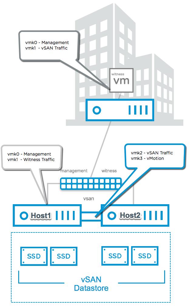
12 clusters, results in three copies of the data, 33% of the reads will come from replica1, 33% of the reads will come from replica2 and 33% will come from replica3. In a vsan Stretched Cluster, we wish to avoid increased latency caused by reading across the inter-site link. To insure that 100% of reads, occur in the site the VM resides on, the read locality mechanism was introduced. Read locality overrides the NumberOfFailuresToTolerate=1 policy s behavior to distribute reads across the components. DOM, the Distributed Object Manager in vsan, takes care of this. DOM is responsible for the creation of virtual machine storage objects in the vsan cluster. It is also responsible for providing distributed data access paths to these objects. There is a single DOM owner per object. There are 3 roles within DOM; Client, Owner and Component Manager. The DOM Owner coordinates access to the object, including reads, locking and object configuration and reconfiguration. All objects changes and writes also go through the owner. The DOM owner of an object will now take into account which fault domain the owner runs in a vsan Stretched Cluster configuration, and will read from the replica that is in the same domain. There is now another consideration with this read locality. One must avoid unnecessary vmotion of the virtual machine between sites. Since the read cache blocks are stored on one site, if the VM moves around freely and ends up on the remote site, the cache will be cold on that site after the move. (Note that this only applies to hybrid configurations, as all-flash configurations do not have an explicit read cache.) Now there will be sub-optimal performance until the cache is warm again. To avoid this situation, soft affinity rules are used to keep the VM local to the same site/fault domain where possible. The steps to configure such rules will be shown in detail in the vsphere DRS section of this guide. VMware vsan 6.2 introduced Client Cache, a mechanism that allocates 0.4% of host memory, up to 1GB, as an additional read cache tier. Virtual machines leverage the Client Cache of the host they are running on. Client Cache is not associated with Stretched Cluster read locality, and runs independently. 3.4 Witness Traffic Separation (WTS) By default, when using vsan Stretched Clusters or 2 Node configurations, the Witness VMkernel interface tagged for vsan traffic must have connectivity with each vsan data node's VMkernel interface tagged with vsan traffic. In vsan 6.5, an alternate VMkernel interface can be designated to carry traffic destined for the Witness rather than the vsan tagged VMkernel interface. This feature allows for more flexible network configurations by allowing for separate networks for node-to-node and node-to-witness traffic. 2 Node Direct Connect This Witness Traffic Separation provides the ability to directly connect vsan data nodes in a 2 Node configuration. Traffic destined for the Witness host can be tagged on an alternative interface from the directly connected vsan tagged interface. 12
13 13
14 In the illustration above, the configuration is as follows: Host 1 vmk0 - Tagged for Management Traffic vmk1 - Tagged for Witness Traffic - This must* be done using esxcli vsan network ip add -i vmk1 -T=witness vmk2 - Tagged for vsan Traffic vmk3 - Tagged for vmotion Traffic Host 2 vmk0 - Tagged for Management Traffic vmk1 - Tagged for Witness Traffic - This must* be done using esxcli vsan network ip add -i vmk1 -T=witness vmk2 - Tagged for vsan Traffic vmk3 - Tagged for vmotion Traffic vsan Witness Appliance vmk0 - Tagged for Management Traffic*** vmk1 - Tagged for vsan Traffic**** *Enabling Witness Traffic is not available from the vsphere Web Client. **Any VMkernel port, not used for vsan Traffic, can be used for Witness Traffic. In a more simplistic configuration, the Management VMkernel interface (vmk0) could be tagged for Witness Traffic. The VMkernel port used, will be required to have connectivity to the vsan Traffic tagged interface on the vsan Witness Appliance. ***The vmk0 VMkernel Interface, which is used for Management traffic may also be used for vsan Traffic. In this situation, vsan Traffic must be unchecked from vmk1. ****The vmk1 VMkernel interface must not have an address that is on the same subnet as vmk0. Because vsan uses the default tcp/ip stack, in cases where vmk0 and vmk1 are on the same subnet, traffic will use vmk0 rather than vmk1. This is detailed in KB Vmk1 should be configured with an address on a different subnet than vmk0. The ability to connect 2 Nodes directly removes the requirement for a high speed switch. This design can be significantly more cost effective when deploying tens or hundreds of 2 Node clusters. vsan 2 Node Direct Connect was announced with vsan 6.5, and is available with vsan 6.6, 6.5, and 6.2*. *6.2 using vsphere 6.0 Patch 3 or higher without an RPQ. Stretched Cluster Configurations Witness Traffic Separation is not supported on Stretched Cluster configurations. 3.5 Per Site Policies Per Site Policies for vsan 6.6 Stretched Clusters Prior to vsan 6.6 Up until vsan 6.6, protection of objects in a Stretched Cluster configuration was comprised of one copy of data at each site and a witness component residing on the Witness host. This configuration provided protection from a single failure in any 1 of the 3 sites, due to each site being configured as a Fault Domain. Using existing policies, 3 Fault Domains allow for a maximum number of a single failure. 14

15 During normal operation, this was not a significant issue. In the event of a device or node failure, additional traffic could potentially traverse the inter-site link for operations such as servicing VM reads and writes, as well as repairing the absent or degraded replica. Stretched Cluster bandwidth sizing is sized based on the number of writes a cluster requires. Capacity for resync operations are taken into account with 25% of the available bandwidth allocated. Reads however are not taken into account normally in sizing. Impact during when an object is absent or degraded Availability scenarios differ depending on the type of failure or lack of availability. If a host goes offline, or a capacity device is unmounted, the components will not be replaced until either the 60 minute threshold is reached. This is configurable, but VMware recommends not to adjust this setting. During the timeframe that the object is absent, if the object is present on the alternate site from the virtual machine, reads from the object will cause additional overhead while traversing the inter-site link. Resycs will not occur until after 60 minutes. After the 60 minute threshold occurs, reads and resyncs will traverse the inter-site link until the object is replaced on the site it is absent from. When a device fails due to a hardware error, data is immediately resynched to repair the object data. Like an absent object after the 60 minute threshold, a degraded event will cause immediate reads and resyncs across the inter-site link. The impact can be insignificant if there are few items that need to be replaced or if the inter-site link is oversized. The impact can be significant if there are many items to be replaced or the inter-site link is already at full utilization. Also consider that an additional failure until the object is repaired will cause the object(s) to become inaccessible. This is because up until vsan 6.6, Stretched Clusters only protect from a single failure. 15
16 New Policy Rules in vsan 6.6 In vsan 6.6 a few rule changes were introduced. Use of these rules provide additional protection or flexibility for Stretched Cluster scenarios. Failures to Tolerate is now called Primary Failures To Tolerate, this is the only rule that received a name change. It still behaves the same, and in a Stretched Cluster, the only possible values are 0 or 1. Failure Tolerance Method has not changed, but when used in conjunction with another rule, it change change object placement behavior. Secondary Failures To Tolerate is a new rule that specifically changes the local protection behavior of objects in each site of a vsan 6.6 Stretched Cluster. The final new rule is Affinity. This rule is only applicable when Primary Failures To Tolerate is 0. When Primary Failures To Tolerate is 0, this rule provides the administrator the ability to choose which site the vsan object should reside on, either the Preferred or Secondary Fault Domain. These new policy rules provide: Local Protection for objects on vsan 6.6 Stretched Clusters Site Affinity for objects vsan 6.6 Stretched Clusters when protection across sites is not desired. New Rule Old Rule Behavior Specific to Stretched Clusters vsan 6.6 Requirements Stretched Cluster Possible Values Primary Failures To Tolerate (PFTT) Failures to Tolerate (FTT) Available for traditional vsan or Stretched Cluster vsan configurations. Specific to Stretched Clusters, this rule determines whether an object is protected on each site or only on a single site On-Disk Format v5 1 - Enables Protection Across Sites 0 - Protection in a Single Site Secondary Failures To Tolerate (SFTT) Only available for vsan 6.6 Stretched Clusters and defines the number of disk or host failures a storage object can tolerate. On-Disk Format v5 Stretched Cluster Proper local and remote host count to satisfy Failure Protection Method and Number of Failures independently 0, 1, 2, 3 - Local protection FTT 16
17 New Rule Old Rule Behavior Specific to Stretched Clusters vsan 6.6 Requirements Stretched Cluster Possible Values Failure Tolerance Method (FTM) Failure Protection Method Performance 2n+1 hosts for Mirroring (0,1,2,3) 2n+2 hosts for Erasure Coding (1,2) RAID1 (Mirroring) - Performance RAID5/6 (Erasure Coding) - Capacity* *All-Flash only Affinity Provides a choice of the Preferred or Secondary Fault Domain for vsan object placement. On-Disk Format v5 Stretched Cluster Primary Failures to Tolerate = 0 Preferred Fault Domain Secondary Fault Domain The only upgrade requirement for vsan 6.5 customers to use the new rules in vsan 6.6, is the requirement to upgrade the On-Disk format from Version 3 to Version 5. Bandwidth requirements do not change. Upon upgrade from a vsan 6.5 Stretched Cluster to a vsan 6.6 Stretched Cluster, an existing Stretched Cluster policy of FTT=1 with FTM=Mirroring will become a PFTT=1, FTM=Mirroring. Secondary Failures To Tolerate Failure Tolerance Method Hosts Required Per Site Hosts Recommended Per Site Mirroring 3 4 (Hybrid or All- 2 Flash architecture) Erasure Coding 4 5 (requires All-Flash 2 architecture) 6 7 Data access behavior using the new Policy Rules vsan Stretched Clusters have traditionally written a copy of data to each site using a Mirroring Failure Tolerance Method. These were full writes to each site, with reads being handled locally using the Site Affinity feature. Write operations are dependent on VM Storage Policy rules in a vsan 6.6 Stretched Cluster. Primary Failures To Tolerate behavior When a Primary Failures to Tolerate rule is equal to 1, writes will continue to be written in a mirrored fashion across sites. 17
18 When a Primary Failures to Tolerate rule is equal to 0, writes will only occur in the site that is specified in the Affinity rule. Reads continue to occur from the site a VM resides on. Secondary Failures To Tolerate behavior Affinity When a Secondary Failures to Tolerate rule is in place, the behavior within a site adheres to the Failure Tolerance Method rule. As illustrated in the above table, the number of failures to tolerate, combined with the Failure Tolerance Method, determine how many hosts are required per site to satisfy the rule requirements. Writes and reads occur within each site in the same fashion as they would in a traditional vsan cluster, but per site. Only when data cannot be repaired locally, such as cases where the only present copies of data reside on the alternate site, will data be fetched from the alternate site. The Affinity rule is only used to specify which site a vsan object, either Preferred or Secondary, will reside on. It is only honored when a Primary Failures To Tolerate rule is set to 0. VMware recommends that virtual machines are run on the same site that their vsan objects reside on. Because the Affinity rule is a Storage Policy rule, it only pertains to vsan objects and not virtual machine placement. This is because read and write operations will be required to traverse the inter-site link when the virtual machine and vsan objects do not reside in the same site. vsan Stretched Cluster Capacity Sizing when using Per-Site Policy Rules Prior to Per-Site policy rules, vsan Stretched Cluster capacity sizing was primarily based on the Mirroring Failure Tolerance Method, assuming a FTT=1. This is because only a single copy of data resided in each site. With Per-Site Policy Rules, capacity requirements can change entirely based on Policy Rule requirements. The following table illustrates some capacity sizing scenarios based on a default site policy with a vmdk requiring 100GB. For single site scenarios, assuming Preferred Site. vsan Version Protection FTT/ PFTT FTM SFTT Capacity Required in Preferred Site Capacity Required in Secondary Site Capacity Requirement PrevSAN 6.6 Across Sites Only 1 Mirroring NA 100GB 100GB 2x vsan 6.6 Across Sites Only 1 Mirroring 0 100GB 100GB 2x 18
19 vsan Version Protection FTT/ PFTT FTM SFTT Capacity Required in Preferred Site Capacity Required in Secondary Site Capacity Requirement Across Sites with Local Mirroring (RAID1 Single Failure) 1 Mirroring 1 200GB 200GB 4x Across Sites with Local Mirroring (RAID1 Double Failure) 1 Mirroring 2 300GB 300GB 6x Across Sites with Local Mirroring (RAID1 Triple Failure) 1 Mirroring 3 400GB 400GB 8x Across Sites with Local Erasure Coding (RAID5/ Single Failure) 1 Erasure Coding 1 133GB 133GB 2.66x Across Sites with Local Erasure Coding (RAID6/ Double Failure) 1 Erasure Coding 2 150GB 150GB 3x Single Site with Mirroring (RAID1 Single Failure) 0 Mirroring 1 200GB 0 2x 19
20 vsan Version Protection FTT/ PFTT FTM SFTT Capacity Required in Preferred Site Capacity Required in Secondary Site Capacity Requirement Single Site with Mirroring (RAID1 Double Failure) 0 Mirroring 2 300GB 0 3x Single Site with Mirroring (RAID1 Triple Failure) 0 Mirroring 3 400GB 0 4x Single Site with Erasure Coding (RAID5/ Single Failure) 0 Erasure Coding 1 133GB 0 1.3x Single Site with Erasure Coding (RAID6/ Double Failure) 0 Erasure Coding 2 150GB 0 1.5x vsan Stretched Cluster Witness Bandwidth considerations when using Per-Site Policy Rules As Per-Site Policy Rules add local protection, object are distributed into even more components. Because the bandwidth requirements to the Witness Host are based on the number of components, using these policy rules will increase the overall component count. The following is an example of the impact of changing a Storage Policy to include local protection in a Stretched Cluster scenario, with a virtual machine with a single vmdk that is smaller than 255GB Using Pre-vSAN 6.6 Policy Rules Would consume 9 components 3 Components for the vmdk (1 in the Preferred Site, 1 in the Secondary Site, 1 on the Witness Host) *Up to a vmdk size of 255GB 20
 3 Components for the Virtual Swap file (1 in the")
 and Mirroring (RAID1 Single")
 *Up to a vmdk")
21 3 Components for the VM Home space (1 in the Preferred Site, 1 in the Secondary Site, 1 on the Witness Host) 3 Components for the Virtual Swap file (1 in the Preferred Site, 1 in the Secondary Site, 1 on the Witness Host) Using vsan 6.6 Policy Rules with Protection across sites (PFTT=1) and Mirroring (RAID1 Single Failure) within Sites Would consume 17 components 7 Components for the vmdk (3 in the Preferred Site, 3 in the Secondary Site, 1 on the Witness Host) *Up to a vmdk size of 255GB 21
 3 Components for the Virtual Swap file (1 in the")
 and Erasure Coding (RAID5")
 *Up to a")
22 7 Components for the VM Home space (3 in the Preferred Site, 3 in the Secondary Site, 1 on the Witness Host) 3 Components for the Virtual Swap file (1 in the Preferred Site, 1 in the Secondary Site, 1 on the Witness Host) Using vsan 6.6 Policy Rules with Protection across sites (PFTT=1) and Erasure Coding (RAID5 Single Failure) within Sites Would consume 21 components 9 Components for the vmdk (4 in the Preferred Site, 4 in the Secondary Site, 1 on the Witness Host) *Up to a vmdk size of 255GB 22
 3 Components for the Virtual Swap file (1 in the")
 and Mirroring (RAID1")

23 9 Components for the VM Home space (4 in the Preferred Site, 4 in the Secondary Site, 1 on the Witness Host) 3 Components for the Virtual Swap file (1 in the Preferred Site, 1 in the Secondary Site, 1 on the Witness Host) Using vsan 6.6 Policy Rules with Protection in a single site (PFTT=0) and Mirroring (RAID1 Single Failure) - Preferred Fault Domain shown below Would consume 9 components 3 Components for the vmdk (3 in the Preferred Site, 0 in the Secondary Site, 0 on the Witness Host) 23
 Using vsan 6.")
24 *Up to a vmdk size of 255GB 3 Components for the VM Home space (3 in the Preferred Site, 0 in the Secondary Site, 0 on the Witness Host) 3 Components for the Virtual Swap file (1 in the Preferred Site, 1 in the Secondary Site, 1 on the Witness Host) Using vsan 6.6 Policy Rules with Protection in a single site (PFTT=0) and Erasure Coding (RAID5 Single Failure) - Preferred Fault Domain shown below Would consume 11 components 4 Components for the vmdk (4 in the Preferred Site, 0 in the Secondary Site, 0 on the Witness Host) *Up to a vmdk size of 255GB 24
 **Notice in each case that the VM SWAP object retains the PFTT=1 and FTM=Mirroring storage policy. This is because the VM SWAP object has a hardcoded policy.")
.")
25 4 Components for the VM Home space (4 in the Preferred Site, 0 in the Secondary Site, 0 on the Witness Host) 3 Components for the Virtual Swap file (1 in the Preferred Site, 1 in the Secondary Site, 1 on the Witness Host) **Notice in each case that the VM SWAP object retains the PFTT=1 and FTM=Mirroring storage policy. This is because the VM SWAP object has a hardcoded policy. Stretched Cluster configurations can accommodate a maximum of 45,000 components. Implementing the Local Protection Per-Site Policy Rules can increase the overall component count significantly. The example VM configuration used above could allow for up to 5,000 VM's on a Stretched Cluster configuration. That's 9 components X 5,000 VM's = 45,000 components (max). By assigning local protection with Mirroring to the same VM configuration, would allow for almost 2,600 VM's of the same configuration, only by adding local Mirrored protection. Choosing Erasure Coding rather than Mirroring for local protection would reduce the number of identical VMs to about 2,
26 Not every environment is going to be uniform like these calculations might indicate. A vmdk that is larger than 255GB is going to require at least one component for every 255GB chunk. Specifying a Policy Rule of Stripe Width, or possibly breaking a component into smaller chunks after a rebalance is going to increase the component count as well. The witness bandwidth requirement is 2Mbps for every 1000 components. Using this formula, some additional 200 virtual machines with 500GB vmdks (12 components each) using Pre-vSAN 6.6 policies would require 4.8Mbps of bandwidth to the Witness host 3 for swap, 3 for VM home space, 6 for vmdks = components X 200 VMs = 2,400 components 2Mbps for every 1000 is 2.4 X 2Mbps = 4.8Mbps The same 200 virtual machines with 500GB vmdks using vsan 6.6 Policy Rules for Cross Site protection with local Mirroring would require 3 for swap, 7 for VM home space, 14 for vmdks = components X 200 VMs = 4,800 components 2Mbps for every 1000 is 4.8 X 2Mbps = 9.6Mbps The same 200 virtual machines with 500GB vmdks using vsan 6.6 Policy Rules for Cross Site protection with local Erasure Coding would require 3 for swap, 9 for VM home space, 18 for vmdks = components X 200 VMs = 6,000 components 2Mbps for every 1000 is 6 X 2Mbps = 12Mbps These examples show that by adding local protection, component counts increase, as well as witness bandwidth requirements. vsan 6.6 Per-Site Policy Rules Summary With the introduction of Per-Site Policy Rules, vsan 6.6 adds two important capabilities to vsan Stretched Clusters. 1. Local Protection 2. Site Affinity As these features provide additional protection and data availability, it is important to consider capacity and bandwidth sizing scenarios. 26
27 4. Requirements List of requirements for implementing vsan Stretched Cluster. 27
28 4.1 VMware vcenter Server A vsan Stretched Cluster configuration can be created and managed by a single instance of VMware vcenter Server. Both the Windows version and the vcenter Server Appliance are supported for configuration and management of a vsan Stretched Cluster. 4.2 A Witness Host In a vsan Stretched Cluster, the witness components are only ever placed on the Witness host. Either a physical ESXi host, or a special vsan Witness Appliance provided by VMware, can be used as the witness host. If a vsan Witness Appliance is used for the Witness host, it will not consume any of the customer s vsphere licenses. A physical ESXi host that is used as a witness host will need to be licensed accordingly, as this can still be used to provision virtual machines should a customer choose to do so. It is important that the witness host is not added to the vsan cluster. The witness host is selected during the creation of a vsan Stretched Cluster. The witness appliance will have a unique identifier in the vsphere web client UI to assist with identifying that a host is in fact a witness appliance (ESXi in a VM). It is shown as a blue host, as highlighted below: Note: This is only visible when the appliance ESXi witness is deployed. If a physical host is used as the witness, then it does not change its appearance in the web client. A dedicated witness host is required for each Stretched Cluster. 4.3 Networking and Latency Requirements When vsan is deployed in a Stretched Cluster across multiple sites using Fault Domains, there are certain networking requirements that must be adhered to. Layer 2 and Layer 3 Support Both Layer 2 (same subnet) and Layer 3 (routed) configurations are used in a recommended vsan Stretched Cluster deployment. VMware recommends that vsan communication between the data sites be over stretched L2. VMware recommends that vsan communication between the data sites and the witness site is routed over L3. Note: A common question is whether L2 for vsan traffic across all sites is supported. There are some considerations with the use of a stretched L2 domain between the data sites and the witness site, and these are discussed in further detail in the design considerations section of this guide. Another common question is whether L3 for vsan traffic across all sites is supported. While this can work, it is not the VMware recommended network topology for vsan Stretched Clusters at this time. vsan traffic between data sites is multicast. Witness traffic between a data site and the witness site is unicast. This changes to only unicast when all hosts in a vsan cluster has been upgraded to vsan 6.6. Supported Geographical Distances For VMware vsan Stretched Clusters, geographical distances are not a support concern. The key requirement is the actual latency numbers between sites. Data Site to Data Site Network Latency 28
29 Data site to data site network refers to the communication between non-witness sites, in other words, sites that run virtual machines and hold virtual machine data. Latency or RTT (Round Trip Time) between sites hosting virtual machine objects should not be greater than 5msec (< 2.5msec one-way). Data Site to Data Site Bandwidth Bandwidth between sites hosting virtual machine objects will be workload dependent. For most workloads, VMware recommends a minimum of 10Gbps or greater bandwidth between sites. In use cases such as 2 Node configurations for Remote Office/Branch Office deployments, dedicated 1Gbps bandwidth can be sufficient with less than 10 Virtual Machines. Please refer to the Design Considerations section of this guide for further details on how to determine bandwidth requirements. Data Site to Witness Network Latency This refers to the communication between non-witness sites and the witness site. In most vsan Stretched luster configurations, latency or RTT (Round Trip Time) between sites hosting VM objects and the witness nodes should not be greater than 200msec (100msec one-way). In typical 2 Node configurations, such as Remote Office/Branch Office deployments, this latency or RTT is supported up to 500msec (250msec one-way). The latency to the witness is dependent on the number of objects in the cluster. VMware recommends that on vsan Stretched Cluster configurations up to , a latency of less than or equal to 200 milliseconds is acceptable, although if possible, a latency of less than or equal to 100 milliseconds is preferred. For configurations that are greater than , VMware requires a latency of less than or equal to 100 milliseconds. Data Site to Witness Network Bandwidth Bandwidth between sites hosting VM objects and the witness nodes are dependent on the number of objects residing on vsan. It is important to size data site to witness bandwidth appropriately for both availability and growth. A standard rule of thumb is 2Mbps for every 1000 components on vsan. Please refer to the Design Considerations section of this guide for further details on how to determine bandwidth requirements. Inter-Site MTU Consistency Knowledge Base Article details a situation where data nodes have an MTU of 9000 (Jumbo Frames) and the vsan Witness Host has an MTU of The vsan Health Check looks for a uniform MTU size across all VMkernel interfaces that are tagged for traffic related to vsan, and reports any inconsistencies. It is important to maintain a consistent MTU size across all vsan VMkernel interfaces on data nodes and the vsan Witness Host in a vsan Stretched Cluster to prevent traffic fragmentation. As KB indicates, the corrective actions are either to reduce the MTU from 9000 on the data node VMkernel interfaces, or increase the MTU value on the vsan Witness Host's VMkernel interface that is tagged for vsan Traffic. Either of these are acceptable corrective actions. The placement of the vsan Witness Host will likely be the deciding factor in which configuration will be used. Network capability, control, and cost to/from the vsan Witness Host as well as overall performance characteristics on data nodes are items to consider when making this design decision. In situations where the vsan Witness Host VMkernel interface tagged for vsan traffic is not configured to use Jumbo Frames (or cannot due to underlying infrastructure), VMware recommends that all vsan VMkernel interfaces use the default MTU of As a reminder, there is no requirement to use Jumbo Frames with VMkernel interfaces used for vsan. 29
30 5. Configuration Minimums and Maximums The maximum number of virtual machines per ESXi host is unaffected by the vsan Stretched Cluster configuration. 30
31 5.1 Virtual Machines Per Host The maximum number of virtual machines per ESXi host is unaffected by the vsan Stretched Cluster configuration. The maximum is the same as normal vsan deployments. VMware recommends that customers should run their hosts at 50% of maximum number of virtual machines supported in a standard vsan cluster to accommodate a full site failure. In the event of full site failures, the virtual machines on the failed site can be restarted on the hosts in the surviving site. 5.2 Hosts Per Cluster The minimum number of hosts in a vsan Stretched Cluster is 3. In such a configuration, Site 1 will contain a single ESXi host, Site 2 will contain a single ESXi host and then there is a Witness host at the third site, the witness site. The nomenclature for such a configuration is This is commonly referred to as a 2 Node configuration. The maximum number of hosts in a vsan Stretched Cluster is 31. Site 1 contains 15 ESXi hosts, Site 2 contains 15 ESXi hosts, and the Witness host on the third site makes 31. This is referred to as a configuration. 5.3 Witness Host There is a maximum of 1 Witness host per vsan Stretched Cluster. The Witness host requirements are discussed in the Design Considerations section of this guide. VMware provides a fully supported vsan Witness Appliance, in Open Virtual Appliance (OVA) format. This is for customers who do not wish to dedicate a physical ESXi host as the witness. This OVA is essentially a pre-licensed ESXi host running in a virtual machine, and can be deployed on a physical ESXi host at the third site. 5.4 vsan Storage Policies Number of Failures To Tolerate (FTT) - Pre-vSAN 6.6 Primary Number of Failures To Tolerate (PFTT) - vsan 6.6 The FTT/PFTT policy setting, has a maximum of 1 for objects. In Pre-vSAN 6.6 Stretched Clusters FTT may not be greater than 1. In vsan 6.6 Stretched Clusters PFTT may not be greater than 1. This is because Stretched Clusters are comprised of 3 Fault Domains. Secondary Number of Failures To Tolerate (SFTT) - vsan 6.6 When used, the SFTT rule determines the Failure Tolerance Method for local protection in a Stretched Cluster. Failure Tolerance Method (FTM) Failure Tolerance Method rules provide object protection with RAID-1 (Mirroring) for Performance and RAID-5/6 (Erasure Coding) for Capacity. In Pre-vSAN 6.6 Stretched Clusters, Mirroring is the only FTM rule that can be satisfied, due to the 3 fault domains present. Also, when Primary Failures to Tolerate is 1 in a vsan 6.6 Stretched Cluster, data is Mirrored across both sites and is placed based on the Secondary Failure to Tolerate policy along with FTM. 31
32 In vsan 6.6 Stretched Clusters, Erasure Coding can be implemented using local protection, provided the host count and capacity are available. All-Flash vsan is a requirement for supporting Erasure Coding. Affinity Affinity rules are used when the PFTT rule value is 0. This rule has 2 values, Preferred or Secondary. This determines which site an Affinity based vmdk would reside on. Other Policy Rules Other policy settings are not impacted by deploying vsan in a Stretched Cluster configuration and can be used as per a non-stretched vsan cluster. Additional vsan 6.6 Policy Rule Changes Can be found in the Per-Site Policies section Fault Domains Fault domains play an important role in vsan Stretched Clusters. Similar to the Number Of Failures To Tolerate (FTT) policy setting discussed previously, the maximum number of fault domains in a vsan Stretched Cluster is 3. The first fault domain is the Preferred data site, the second fault domain is the Secondary data site and the third fault domain is the Witness host site. 32
33 6. Design Considerations The witness host must be capable of running the same version of ESXi as vsan data nodes. 33
34 6.1 Witness Host Sizing The vsan Witness host can be either a traditional physical ESXi host or the provided and packaged vsan Witness Appliance (OVA). The purpose of the Witness host is to store witness components for virtual machine objects. vsan Witness Appliance (Virtual Machine) Deploying the vsan Witness Appliance that is provided by VMware is the recommended deployment choice for a vsan Witness Host. When choosing this deployment option, there are some requirements to consider. Licensing A license is hard coded in the vsan Witness Appliance and is provided for free from VMware. vsan Witness Appliance Version A vsan Witness Appliance is provided with each release of vsan. The underlying vsphere version is the same as the version running vsan. Upon initial deployment of the vsan Witness Appliance, it is required to be the same as the version of vsan. Example: A new vsan 6.5 deployment requires a 6.5 version of the vsan Witness Appliance. When upgrading the vsan Cluster, upgrade the vsan Witness Appliance in the same fashion as upgrading vsphere. This keeps the versions aligned Example: Upgrade vsan 6.5 hosts to 6.6 using VMware Update Manager. Upgrade vsan Witness Appliance (6.5 to 6.6) using VMware Update Manager. vsan Witness Appliance Size When using a vsan Witness Appliance, the size is dependent on the configurations and this is decided during the deployment process. vsan Witness Appliance deployment options are hard coded upon deployment and there is typically no need to modify these. Compute Requirements The vsan Witness Appliance, regardless of configuration, uses at least two vcpus. Memory Requirements Memory requirements are dependent on the number of components. Storage Requirements Cache Device Size: Each vsan Witness Appliance deployment option has a cache device size of 10GB. This is sufficient for each for the maximum of 45,000 components. In a typical vsan deployment, the cache device must be a Flash/SSD device. Because the vsan Witness Appliance has virtual disks, the 10GB cache device is configured as a virtual SSD. There is no requirement for this device to reside on a physical flash/ssd device. Traditional spinning drives are sufficient. Capacity Device Sizing: First consider that a capacity device can support up to 21,000 components. Also consider that a vsan Stretched Cluster can support a maximum of 45,000 components. Each Witness Component is 16MB, as a result, the largest capacity device that can be used for storing of Witness Components is approaching 350GB. 34
35 vsan Witness Appliance Deployment Sizes & Requirements Summary Tiny - Supports up to 10 VMs/750 Witness Components Compute - 2 vcpus Memory - 8GB vram ESXi Boot Disk - 12GB Virtual HDD Cache Device - 10GB Virtual SSD Capacity Device - 15GB Virtual HDD Normal - Supports up to 500 VMs/21,000 Witness Components Compute - 2 vcpus Memory - 16GB vram ESXi Boot Disk - 12GB Virtual HDD Cache Device - 10GB Virtual SSD Capacity Device - 350GB Virtual HDD Large - Supports over 500 VMs/45,000 Witness Components Compute: 2 vcpus Memory - 32 GB vram ESXi Boot Disk - 12GB Virtual HDD Cache Device - 10GB Virtual SSD Capacity Devices - 3x350GB Virtual HDD 8GB ESXi Boot Disk*, one 10GB SSD, three 350GB HDDs Supports a maximum of 45,000 witness components Where can the vsan Witness Appliance run? The vsan Witness Appliance must run on an ESXi 5.5 or greater host. Several scenarios are supported officially: It can be run in any of the following infrastructure configurations (provided appropriate networking is in place): On a vsphere environment backed with any supported storage (vmfs datastore, NFS datastore, vsan Cluster) On vcloud Air/OVH backed by supported storage Any vcloud Air Network partner hosted solution On a vsphere Hypervisor (free) installation using any supported storage (vmfs datastore or NFS datastore) Support Statements specific to placement of the vsan Witness Appliance on a vsan cluster: The vsan Witness Appliance is supported running on top of another non-stretched vsan cluster. The vsan Witness Appliance is supported on a Stretched Cluster vsan for another vsan Stretched Cluster, and vice-versa. vsan 2-node cluster hosting witness for another vsan 2-node cluster witness, and vice versa, is not recommended and requires an RPQ. Physical Host as a vsan Witness Host If using a physical host as the vsan Witness Host there are some requirements to consider. Licensing 35
36 If using a physical host as a vsan Witness Host, it must be licensed with a valid vsphere license. This does not require the same licensed edition as the vsan Cluster it is supporting. vsphere Build If using a physical host as a vsan Witness Host, it must be running the same build of vsphere as the Stretched Cluster or 2 Node Cluster that it is participating with. Compute and Memory Requirements The minimum specifications required for ESXi meet the minimum requirements for use as a vsan Witness Host. Minimum requirements for vsphere are dependent on the build of vsphere, and can be found in the documentation section for each edition in VMware Documentation: Storage Requirements Storage requirements do not change for a physical host being used as a vsan Witness Host in comparison to the vsan Witness Appliance. An ESXi boot device, a cache device, and one or more capacity devices are still required. Required Optional 1st device - vsphere Boot Device - Normal vsphere Requirements 2nd device - vsan Cache Device - No requirement for Flash/SSD, but it must be tagged as Flash/SSD in ESXi to be used as though it were a Flash/SSD device. This must be at least 10GB in size. 3rd device - Can be up to 350GB and will support metadata for up to 21,000 components on a vsan Cluster 4th device - Can be up to 350GB and will support metadata for up to 21,000 components on a vsan Cluster 5th device - Can be up to 350GB and will support metadata for up to 21,000 components on a vsan Cluster. Other workloads If using a physical host as a vsan Witness Host, it may run other workloads. Because the physical vsan Witness Host is external to the vsan Cluster it is contributing to, those workloads will not be part of the vsan Cluster. The vsan Disk Group, and the disks it includes, may not be used for those workloads. *Important consideration: Multiple vsan Witness Appliances can run on a single physical host. Using vsan Witness Appliances is typically more cost effective than dedicating physical hosts for the purpose of meeting the vsan Witness Host need. 6.2 Cluster Compute Resource Utilization For full availability, VMware recommends that customers should be running at 50% of resource consumption across the vsan Stretched Cluster. In the event of a complete site failure, all of the virtual machines could be run on the surviving site. VMware understands that some customers will want to run levels of resource utilization higher than 50%. While it is possible to run at higher utilization in each site, customers should understand that in the event of failure, not all virtual machines will be restarted on the surviving site. 36
37 With the introduction of Per-Site Policies in vsan 6.6, capacity requirements are dependent on the policies used. vsan Version Protection FTT/ PFTT FTM SFTT Capacity Required in Preferred Site Capacity Required in Secondary Site Capacity Requirement PrevSAN 6.6 Across Sites Only 1 Mirroring NA 100% 100% 200% vsan 6.6 Across Sites Only 1 Mirroring 0 100% 100% 200% Across Sites with Local Mirroring (RAID1 Single Failure) 1 Mirroring 1 200% 200% 400% Across Sites with Local Mirroring (RAID1 Double Failure) 1 Mirroring 2 300% 300% 600% Across Sites with Local Mirroring (RAID1 Triple Failure) 1 Mirroring 3 400% 400% 800% Across Sites with Local Erasure Coding (RAID5/ Single Failure) 1 Erasure Coding 1 133% 133% 266% 37
38 vsan Version Protection FTT/ PFTT FTM SFTT Capacity Required in Preferred Site Capacity Required in Secondary Site Capacity Requirement Across Sites with Local Erasure Coding (RAID6/ Double Failure) 1 Erasure Coding 2 150% 150% 300% Single Site with Mirroring (RAID1 Single Failure) 0 Mirroring 1 200% 0 200% Single Site with Mirroring (RAID1 Double Failure) 0 Mirroring 2 300% 0 300% Single Site with Mirroring (RAID1 Triple Failure) 0 Mirroring 3 400% 0 400% Single Site with Erasure Coding (RAID5/ Single Failure) 0 Erasure Coding 1 133% 0 133% Single Site with Erasure Coding (RAID6/ Single Failure) 0 Erasure Coding 2 150% 0 150% 6.3 Network Design Considerations 38
39 Stretched Cluster Network Design Considerations Sites A vsan Stretched Cluster requires three sites. Data Sites - Contains vsan Data nodes Preferred site - Specified to be the primary owner of vsan objects. This is an important designation specifically in cases of connectivity disruptions. Secondary site Witness Site - Contains vsan Witness host Maintains Witness Component data from Preferred/Secondary sites when applicable *When using "Site Affinity" Witness Components will not reside in the Witness site When using vsan Stretched Clusters in a single datacenter, different rooms, or different racks could be considered separate sites. When using vsan 2 Node, both vsan data nodes are typically in the same physical location. Connectivity and Network Types Preferred Site Secondary Site Witness Site Management Network Connectivity to vcenter & other vsan Hosts Can be Layer 2 or Layer 3 Connectivity to vcenter & other vsan Hosts Can be Layer 2 or Layer 3 Connectivity to vcenter* Can be Layer 2 or Layer 3 VM Network Recommend Layer 2. In the event of site failure VMs restarting on the Secondary site do not require IP address changes Recommend Layer 2. In the event of site failure VMs restarting on the Secondary site do not require IP address changes No requirement for VM Network. Running VMs on the vsan Witness Appliance is not supported. Running VMs on a Physical Witness Host is supported. vmotion Network If vmotion is desired between Data Sites, Layer 2 or Layer 3 are supported vmotion is not required between this Data site & the Witness Site If vmotion is desired between Data Sites, Layer 2 or Layer 3 are supported vmotion is not required between this Data site & the Witness Site There is not requirement for vmotion networking to the Witness site. 39
40 vsan Network To the Secondary Site: Layer 2 or Layer 3 Recommend L2 for Multicast (6.5 & below) Layer 2 or Layer 3 for Unicast (6.6 & above) To the Witness Site: Layer 3 Connectivity to the other sites must be independent. To the Preferred Site: Layer 2 or Layer 3 Recommend L2 for Multicast (6.5 & below) Layer 2 or Layer 3 for Unicast (6.6 & above) To the Witness Site: Layer 3 Connectivity to the other sites must be independent. To the Preferred Site: Layer 3 To the Secondary Site: Layer 3 Connectivity to each site must be independent. Port Requirements VMware vsan requires these ports to be open, both inbound and outbound: Port Protocol Connectivity To/From vsan Clustering Service 12345, 2345 UDP vsan Hosts vsan Transport 2233 TCP vsan Hosts vsan VASA Vendor Provider 8080 TCP vsan Hosts and vcenter vsan Unicast Agent (to Witness Host) UDP vsan Hosts and vsan Witness Appliance TCPIP Stacks, Gateways, and Routing TCPIP Stacks At this time, the vsan traffic does not have its own dedicated TCPIP stack. Custom TCPIP stacks are also not applicable for vsan traffic. Default Gateway on ESXi Hosts ESXi hosts come with a default TCPIP stack. As a result, hosts have a single 40
41 default gateway. This default gateway is associated with the Management VMkernel interface (typically vmk0). It is a best practice to implement storage networking, in this case vsan networking, on an alternate VMkernel interface, with alternate addressing. vsan networking uses the same TCPIP stack as the Management VMkernel interface, traffic defaults to using the same default gateway as the Management VMkernel interface. With the vsan network isolated from the Management VMkernel interface, it is not possible to use the default gateway. Because of this, vsan Data Nodes cannot communicate with the Witness Host by default. One solution to this issue is to use static routes. This allows an administrator to define a new routing entry indicating which path should be followed to reach a particular network. In the case of the vsan network on a vsan Stretched Cluster. Static routes could be added as follows: 1. Hosts on the Preferred Site have a static route added so that requests to reach the witness network on the Witness Site are routed out the vsan VMkernel interface 2. Hosts on the Secondary Site have a static route added so that requests to reach the witness network on the Witness Site are routed out the vsan VMkernel interface 3. The Witness Host on the Witness Site have static route added so that requests to reach the Preferred Site and Secondary Site are routed out the WitnessPg VMkernel interface 4. If using Layer 3 between the Preferred Site & Secondary Sites, static routes may be required to properly communicate across the inter-site link. *Note, this may result in an alert (which may be disregarded provided connectivity is verified) that the vsan network does have a matching subnet. Static routes are added via the esxcli network ip route or esxcfg-route commands. Refer to the appropriate vsphere Command Line Guide for more information. Caution when implementing Static Routes: Using static routes requires administrator intervention. Any new ESXi hosts that are added to the cluster at either site 1 or site 2 needed to have static routes manually added before they can successfully communicate to the witness, and the other data site. Any replacement of the witness host will also require the static routes to be updated to facilitate communication to the data sites. Considerations for 2 Node vsan While 2 Node vsan configurations are essentially a vsan Stretched Cluster, networking considerations are a bit different due to the fact that 2 Node vsan configurations are typically installed in a single location. Because each data node is in the same physical location, independent routing to the Witness Host from each node is not required. Traditional vsan 2 Node Configurations From the initial offering of 2 Node vsan, the vsan network must be able to reach the Witness Host's VMkernel interface tagged for vsan Traffic. The same static routing requirements mentioned above are required for the vsan VMkernel interface with one exception. With both hosts residing in the same location, the same gateway would be used. 41
42 2 Node Direct Connect Configurations Witness Traffic Separation (WTS) support was introduced in vsan 6.5. Metadata traffic destined for the Witness Host may be sent using an alternate VMkernel interface. This is accomplished by tagging an alternate VMkernel interface with "Witness Traffic". By redirecting metadata communication with the Witness Host, vsan data can occur directly between data nodes. The ability to Direct Connect the data nodes for vsan data removes the requirement for a switch. Hosts with onboard 10GbE connectivity can be very cost effective in a 2 Node Direct Connect configuration. While 2 Node Direct Connect became officially supported with the release of vsan 6.5, the code shipped with some builds of vsan 6.2. As a result, 2 Node Direct is also supported on vsan 6.2, specifically with builds starting with ESXi 6.0 Update 3. Note that vcenter must also be at version 6.0 Update 3 to use Direct Connect with 2 Node vsan. vsan Witness Appliance Networking When deploying 2 Node vsan with Direct Connect, it may be desired to use only the Management interface (vmk0) of a vsan Witness Appliance instead of the dedicated WitnessPg VMkernel interface (vmk1). This is a supported configuration. This is not recommended for 2 Node vsan configurations that are not using the Direct Connect feature (Witness Traffic Separation). Additionally, the IP address of the Management VMkernel interface (vmk0) and the WitnessPg VMkernel interface (vmk1) cannot reside on the same subnet. This is because, as mentioned above, that vsan uses the default TCPIP stack, as does ESXi management. If vmk0 (Management) and vmk1 (vsan Traffic) are configured on the same segment, vsan Traffic will flow through the Management interface (vmk0) rather than the interface used for vsan Traffic (vmk1). This is not a supported configuration, and will result in vsan Health Check errors. This is a multi-homing issue and is addressed in KB article : Topology - L2 Design Versus L3 Design Consider a design where the vsan Stretched Cluster is configured in one large L2 design as follows, where the Preferred Site (Site 1) and Secondary Site (Site 2) are where the virtual machines are deployed. The Witness site contains the Witness Host: 42

43 In the event of the link between Switch 1 and Switch 2 is broken (the link between the Site 1 and Site 2). Network traffic will now route from Site 1 to Site 2 via Site 3. Considering there is a much lower bandwidth requirement for connectivity to the Witness Host, customers would see a decrease in performance if network traffic is routed through a lower specification Site 3. If there are situations where routing traffic between data sites through the witness site does not impact latency of applications, and bandwidth is acceptable, a stretched L2 configuration between sites is supported. However, in most cases, VMware feels that such a configuration is not feasible for the majority of customers. To avoid the situation outlined, and to ensure that data traffic is not routed through the Witness Site, VMware recommends the following network topology: Between Site 1 and Site 2, implement either a stretched L2 (same subnet) or a L3 (routed) configuration. Implement an L3 (routed) configuration between data sites and the Witness site. Ensure that Sites 1 and 2 can only connect to Site 3 directly, and not through the alternate site. Static routing will be required from data hosts (Site 1 & Site 2) to the Witness in Site 3. Hosts in Site 1 should never traverse the inter-site link to reach Site 3. Hosts in Site 2 should never traverse the inter-site link to reach Site 3. Static routing will be required from the Witness host (Site 3) to the data hosts (Site 1 & Site 2) The Witness should never route through Site 1, then across the inter-site link to reach Site 2. The Witness should never route through Site 2, then across the inter-site link to reach Site 1. In the event of a failure on either of the data sites network, this configuration will also prevent any traffic from Site 1 being routed to Site 2 via Witness Site 3, and thus avoid any performance degradation. 43
44 *If connectivity between the vsan Network is configured to use L3: Each host in Site 1 will require a static route for the vsan VMkernel interface to route across the inter-site link to each vsan VMkernel interface for hosts in Site 2. Each host in Site 2 will require a static route for the vsan VMkernel interface to route across the inter-site link to each vsan VMkernel interface for hosts in Site Config of Network from Data Sites to Witness The next question is how to implement such a configuration, especially if the witness host is on a public cloud? How can the interfaces on the hosts in the data sites, which communicate to each other over the vsan network, communicate to the witness host? Option 1: Physical Witness on-premises connected over L3 & static routes In this first configuration, the data sites are connected over a stretched L2 network. This is also true for the data sites management network, vsan network, vmotion network and virtual machine network. The physical network router in this network infrastructure does not automatically route traffic from the hosts in the data sites (Site 1 and Site 2) to the host in the Site 3. In order for the vsan Stretched Cluster to be successfully configured, all hosts in the cluster must communicate. How can a stretched cluster be deployed in this environment? The solution is to use static routes configured on the ESXi hosts so that the vsan traffic from Site 1 and Site 2 is able to reach the witness host in Site 3, and vice versa. While this is not a preferred configuration option, this setup can be very useful for proof-of-concept design where there may be some issues with getting the required network changes implemented at a customer site. In the case of the ESXi hosts on the data sites, a static route must be added to the vsan VMkernel interface which will redirect traffic for the witness host on the witness site via a default gateway for that network. In the case of the witness host, the vsan interface must have a static route added which redirects vsan traffic destined for the data sites hosts. Adding static routes is achieved using the 44

45 esxcfg-route a command on the ESXi hosts. This will have to be repeated on all ESXi hosts in the stretched cluster. For this to work, the network switches need to be IP routing enabled between the vsan network VLANs, in this example VLANs 11 and 21. Once requests arrive for a remote host (either witness -> data or data -> witness), the switch will route the packet appropriately. This communication is essential for vsan Stretched Cluster to work properly. Note that we have not mentioned the ESXi management network here. The vcenter server will still be required to manage both the ESXi hosts at the data sites and the ESXi witness. In many cases, this is not an issue for customer. However, in the case of stretched clusters, it might be necessary to add a static route from the vcenter server to reach the management network of the witness ESXi host if it is not routable, and similarly a static route may need to be added to the ESXi witness management network to reach the vcenter server. This is because the vcenter server will route all traffic via the default gateway. As long as there is direct connectivity from the witness host to vcenter (without NAT ing), there should be no additional concerns regarding the management network. Also note that there is no need to configure a vmotion network or a VM network or add any static routes for these network in the context of a vsan Stretched Cluster. This is because there will never be a migration or deployment of virtual machines to the vsan Witness host. Its purpose is to maintain witness objects only, and does not require either of these networks for this task. Option 2: Virtual Witness on-premises connected over L3 & static routes Requirements: Since the virtual ESXi witness is a virtual machine that will be deployed on a physical ESXi host when deployed on-premises, the underlying physical ESXi host will need to have a minimum of one VM network preconfigured. This VM network will need to reach both the management network and the vsan network shared by the ESXi hosts on the data sites. An alternative option that might be simpler to implement is to have two preconfigured VM networks on the underlying physical ESXi host, one for the management network and one for the vsan network. When the virtual ESXi witness is deployed on this physical ESXi host, the network will need to be attached/configured accordingly. Once the vsan Witness Appliance has been successfully deployed, the static route configuration must be configured. As before, the data sites are connected over a stretched L2 network. This is also true for data sites management network, vsan network, vmotion network and virtual machine network. Once again, the physical network router in this environment does not automatically route traffic from the hosts in the Preferred and Secondary data sites to the host in the witness site. In order for the vsan Stretched Cluster to be successfully configured, all hosts in the cluster require static routes added so that the vsan traffic from the Preferred and Secondary sites is able to reach the Witness host in the witness site, and vice versa. As mentioned before, this is not a preferred configuration option, but this setup can be very useful for proof-of-concept design where there may be some issues with getting the required network changes implemented at a customer site. 45
46 Once again, the static routes are added using the esxcfg-route a command on the ESXi hosts. This will have to be repeated on all ESXi hosts in the cluster, both on the data sites and on the witness host. The switches should be configured to have IP routing enabled between the vsan network VLANs on the data sites and the witness site, in this example VLANs 11 and 21. Once requests arrive for the remote host (either witness -> data or data -> witness), the switch will route the packet appropriately. With this setup, the vsan Stretched Cluster will form. Note that once again we have not mentioned the management network here. As mentioned before, vcenter needs to manage the remote ESXi witness and the hosts on the data sites. If necessary, a static route should be added to the vcenter server to reach the management network of the witness ESXi host, and similarly a static route should be added to the ESXi witness to reach the vcenter server. Also note that, as before, that there is no need to configure a vmotion network or a VM network or add any static routes for these network in the context of a vsan Stretched Cluster. This is be cause there will never be a migration or deployment of virtual machines to the vsan witness. Its purpose is to maintain witness objects only, and does not require either of these networks for this task. Option 3: 2 Node Configuration for Remote Office/Branch Office Deployment In the use case of Remote Office/Branch Office (ROBO) deployments, it is common to have 2 Node configurations at one or more remote offices. This deployment model can be very cost competitive when a running a limited number of virtual machines no longer require 3 nodes for vsan. 46


47 VMware vsan 2 Node configurations are vsan Stretched Clusters comprised of two data nodes and one witness node. This is a Stretched Cluster configuration. Each data node behaves as a data site, and the two nodes are typically in the same location. The witness VM could reside at the primary data center or another location. Management traffic for the data nodes is typically automatically routed to the vcenter server at the central data center. Routing for the vsan network, as shown in previous scenarios, will require static routes between the vsan interfaces on each data node and the witness VM running in the central data center. Because they reside in the same physical location, networking between data nodes is consistent with that of a traditional vsan cluster. Data nodes still require a static route to the vsan Witness host residing in the central data center. The vsan Witness Appliance's secondary interface, designated for vsan traffic will also require a static route to each of data node s vsan traffic enabled VMkernel interface. Adding static routes is achieved using the esxcfg-route a command on the ESXi hosts and witness VM. In the illustration above, the central data center management network is on VLAN 10. For vcenter to manage each of the 2 node (ROBO) deployments, there must be a route to each host s management network. This could be on an isolated management VLAN, but it is not required. Depending on the network configuration, vcenter itself may require static routes to each of the remote ESXi host management VMkernel interfaces. All the normal requirements for vcenter to connect to ESXi hosts should be satisfied. The management VMkernel for the witness VM, in the central data center, can easily reside on the same management VLAN in the central data center, not requiring any static routing. The vsan network in each site must also have routing to the respective witness VM vsan interface. 47

48 Because the VMkernel interface with vsan traffic enabled uses the same gateway, static routes will be required to and from the data nodes to the vsan Witness Appliances. Remember a vsan Witness Appliance will never run an VM workloads, and therefore the only traffic requirements are for management and vsan witness traffic, because its purpose is to maintain witness objects only. For remote site VMs to communicate with central data center VMs, appropriate routing for the VM Network will also be required. Technical Note: Witness Appliance Placement Witness Appliances may not be placed on an alternate Stretched Cluster. The illustration shows a dual 2 Node configuration, Clusters A & B, each housing the Witness Appliance for the alternate cluster. This is not a recommended configuration but can be supported if an RPQ has been granted. Please engage your VMware representative to inquire about this configuration. 6.5 Bandwidth Calculation As stated in the requirements section, the bandwidth requirement between the two main sites is dependent on workload and in particular the number of write operations per ESXi host. Other factors such as read locality not in operation (where the virtual machine resides on one site but reads data from the other site) and rebuild traffic, may also need to be factored in. Requirements Between Data Sites Reads are not included in the calculation as we are assuming read locality, which means that there should be no inter-site read traffic. The required bandwidth between the two data sites (B) is equal to the Write bandwidth (Wb) * data multiplier (md) * resynchronization multiplier (mr): B = Wb *md * mr The data multiplier is comprised of overhead for vsan metadata traffic and miscellaneous related operations. VMware recommends a data multiplier of 1.4. The resynchronization multiplier is included to account for resynchronizing events. It is recommended to allocate bandwidth capacity on top of required bandwidth capacity for resynchronization events. Making room for resynchronization traffic, an additional 25% is recommended. Data Site to Data Site Example 1 48
49 Take a hypothetical example of a 6 node vsan Stretched Cluster (3+3+1) with the following: A workload of 35,000 IOPS 10,000 of those being write IOPS A typical 4KB size write (This would require 40MB/s, or 320Mbps bandwidth) Including the vsan network requirements, the required bandwidth would be 560Mbps. B = 320 Mbps * 1.4 * 1.25 = 560 Mbps. Data Site to Data Site Example 2 Take a 20 node vsan Stretched Cluster ( ) with a VDI (Virtual Desktop Infrastructure) with the following: A workload of 100,000 IOPS With a typical 70%/30% distribution of writes to reads respectively, 70,000 of those are writes. A typical 4KB size write(this would require 280 MB/s, or 2.24Gbps bandwidth) Including the vsan network requirements, the required bandwidth would be approximately 4Gbps. B = 280 Mbps * 1.4 * 1.25 = 3,920 Mbps or 3.92Gbps Using the above formula, a vsan Stretched Cluster with a dedicated 10Gbps inter-site link, can accommodate approximately 170,000 4KB write IOPS. Customers will need to evaluate their I/O requirements but VMware feels that 10Gbps will meet most design requirements. Above this configuration, customers would need to consider multiple 10Gb NICs teamed, or a 40Gb network. While it might be possible to use 1Gbps connectivity for very small vsan Stretched Cluster implementations, the majority of implementations will require 10Gbps connectivity between sites. Therefore, VMware recommends a minimum of 10Gbps network connectivity between sites for optimal performance and for possible future expansion of the cluster. Requirements when Read Locality is not Available Note that the previous calculations are only for regular Stretched Cluster traffic with read locality. If there is a device failure, read operations also have to traverse the inter-site network. This is because the mirrored copy of data is on the alternate site when using NumberOfFailurestoTolerate=1. The same equation for every 4K read IO of the objects in a degraded state would be added on top of the above calculations. The expected read IO would be used to calculate the additional bandwidth requirement. In an example of a single failed disk, with objects from 5 VMs residing on the failed disk, with 10,000 (4KB) read IOPS, an additional 40 Mbps, or 320 mbps would be required, in addition to the above Stretched Cluster requirements, to provide sufficient read IO bandwidth, during peak write IO, and resync operations. Requirements Between Data Sites and the Witness Site Witness bandwidth isn t calculated in the same way as bandwidth between data sites. Because hosts designated as a witness do not maintain any VM data, but rather only component metadata, the requirements are much smaller. Virtual Machines on vsan are comprised of multiple objects, which can potentially be split into multiple components, depending on factors like policy and size. The number of components on vsan have a direct impact on the bandwidth requirement between the data sites and the witness. 49
50 The required bandwidth between the Witness and each site is equal to ~1138 B x Number of Components /5s 1138 B x NumComp / 5 seconds The 1138 B value comes from operations that occur when the Preferred Site goes offline, and the Secondary Site takes ownership of all of the components. When the primary site goes offline, the secondary site becomes the master. The Witness sends updates to the new master, followed by the new master replying to the Witness as ownership is updated. The 1138 B requirement for each component comes from a combination of a payload from the Witness to the backup agent,followed by metadata indicating that the Preferred Site has failed. In the event of a Preferred Site failure, the link must be large enough to allow for the cluster ownership to change, as well ownership of all of the components within 5 seconds. Witness to Site Examples Workload 1 With a VM being comprised of 3 objects {VM namespace, vmdk (under 255GB), and vmswap) Failure to Tolerate of 1 (FTT=1) Stripe Width of 1 Approximately 166 VMs with the above configuration would require the Witness to contain 996 components. To successfully satisfy the Witness bandwidth requirements for a total of 1,000 components on vsan, the following calculation can be used: Converting Bytes (B) to Bits (b), multiply by 8 B = 1138 B * 8 * 1,000 / 5s = 1,820,800 Bits per second = 1.82 Mbps VMware recommends adding a 10% safety margin and round up. B + 10% = 1.82 Mbps Kbps = 2.00 Mbps With the 10% buffer included, a rule of thumb can be stated that for every 1,000 components, 2 Mbps is appropriate. Workload 2 With a VM being comprised of 3 objects {VM namespace, vmdk (under 255GB), and vmswap) Failure to Tolerate of 1 (FTT=1) Stripe Width of 2 Approximately 1,500 VMs with the above configuration would require 18,000 components to be stored on the Witness. To successfully satisfy the Witness bandwidth requirements for 18,000 components on vsan, the resulting calculation is: B = 1138 B * 8 * 18,000 / 5s = 32,774,400 Bits per second = Mbps B + 10% = Mbps Mbps = Mbps Using the general equation of 2Mbps for every 1,000 components, (NumComp/1000) X 2Mbps, it can be seen that 18,000 components does in fact require 36 Mbps. 50
51 6.6 The Role of vsan Heartbeats As mentioned previously, when vsan is deployed in a stretched cluster configuration, the vsan master node is placed on the preferred site and the vsan backup node is placed on the secondary site. So long as there are nodes (ESXi hosts) available in the Preferred site, then a master is always selected from one of the nodes on this site. Similarly, for the Secondary site, so long as there are nodes available on the secondary site. The vsan master node and the vsan backup node send heartbeats every second. If communication is lost for 5 consecutive heartbeats (5 seconds) between the master and the backup due to an issue with the backup node, the master chooses a different ESXi host as a backup on the remote site. This is repeated until all hosts on the remote site are checked. If there is a complete site failure, the master selects a backup node from the Preferred site. A similar scenario arises when the master has a failure. When a node rejoins an empty site after a complete site failure, either the master (in the case of the node joining the primary site) or the backup (in the case where the node is joining the secondary site) will migrate to that site. If communication is lost for 5 consecutive heartbeats (5 seconds) between the master and the Witness, the Witness is deemed to have failed. If the Witness has suffered a permanent failure, a new Witness host can be configured and added to the cluster. 51
52 7. Cluster Settings vsphere HA Certain vsphere HA behaviors have been modified especially for vsan. 52
53 7.1 Cluster Settings vsphere HA Certain vsphere HA behaviors have been modified especially for vsan. It checks the state of the virtual machines on a per virtual machine basis. vsphere HA can make a decision on whether a virtual machine should be failed over based on the number of components belonging to a virtual machine that can be accessed from a particular partition. When vsphere HA is configured on a vsan Stretched Cluster, VMware recommends the following: vsphere HA Host Monitoring Turn on Enabled Host Hardware Monitoring VM Component Protection: Protect against Storage Connectivity Loss Disabled (default) Virtual Machine Monitoring Customer Preference Disabled by default Admission Control Set to 50% Host Isolation Response Power off and restart VMs Datastore Heartbeats Use datastores only from the specified list, but do not select any datastores from the list. This disables Datastore Heartbeats Advanced Settings: das.usedefaultisolationaddress False das.isolationaddress0 IP address on vsan network on site 1 das.isolationaddress1 IP address on vsan network on site Turn on vsphere HA To turn on vsphere HA, select the cluster object in the vcenter inventory, Manage, then vsphere HA. From here, vsphere HA can be turned on and off via a check box. 7.3 Host Monitoring Host monitoring should be enabled on vsan stretch cluster configurations. This feature uses network heartbeat to determine the status of hosts participating in the cluster, and if corrective action is required, such as restarting virtual machines on other nodes in the cluster. 7.4 Admission Control 53

54 Admission control ensures that HA has sufficient resources available to restart virtual machines after a failure. As a full site failure is one scenario that needs to be taken into account in a resilient architecture, VMware recommends enabling vsphere HA Admission Control. Availability of workloads is the primary driver for most stretched cluster environments. Sufficient capacity must therefore be available for a full site failure. Since ESXi hosts will be equally divided across both sites in a vsan Stretched Cluster, and to ensure that all workloads can be restarted by vsphere HA, VMware recommends configuring the admission control policy to 50 percent for both memory and CPU. VMware recommends using the percentage-based policy as it offers the most flexibility and reduces operational overhead. For more details about admission control policies and the associated algorithms we would like to refer to the vsphere 6.5 Availability Guide. The following screenshot shows a vsphere HA cluster configured with admission control enabled using the percentage based admission control policy set to 50%. It should be noted that vsan is not admission-control aware. There is no way to inform vsan to set aside additional storage resources to accommodate fully compliant virtual machines running on a single site. This is an additional operational step for administrators if they wish to achieve such a configuration in the event of a failure. 7.5 Host Hardware Monitoring VM Component Protection vsphere 6.0 introduced a new enhancement to vsphere HA called VM Component Protection (VMCP) to allow for an automated fail-over of virtual machines residing on a datastore that has either an All Paths Down (APD) or a Permanent Device Loss (PDL) condition. A PDL, permanent device loss condition, is a condition that is communicated by the storage controller to ESXi host via a SCSI sense code. This condition indicates that a disk device has become unavailable and is likely permanently unavailable. When it is not possible for the storage controller to communicate back the status to the ESXi host, then the condition is treated as an All Paths Down (APD) condition. In traditional datastores, APD/PDL on a datastore affects all the virtual machines using that datastore. However, for vsan this may not be the case. An APD/PDL may only affect one or few VMs, but not all VMs on the vsan datastore. Also in the event of an APD/PDL occurring on a subset of hosts, there is no guarantee that the remaining hosts will have access to all the virtual machine objects, and be able to restart the virtual machine. Therefore, a partition may result in such a way that the virtual machine is not accessible on any partition. 54
55 Note that the VM Component Protection (VMCP) way of handling a failover is to terminate the running virtual machine and restart it elsewhere in the cluster. VMCP/HA cannot determine the cluster-wide accessibility of a virtual machine on vsan, and thus cannot guarantee that the virtual machine will be able to restart elsewhere after termination. For example, there may be resources available to restart the virtual machine, but accessibility to the virtual machine by the remaining hosts in the cluster is not known to HA. For traditional datastores, this is not a problem, since we know host-datastore accessibility for the entire cluster, and by using that, we can determine if a virtual machine can be restarted on a host or not. At the moment, it is not possible for vsphere HA to understand the complete inaccessibility vs. partial inaccessibility on a per virtual machine basis on vsan; hence the lack of VMCP support by HA for vsan. VMware recommends leaving VM Component Protection (VMCP) disabled. 7.6 Datastore for Heartbeating vsphere HA provides an additional heartbeating mechanism for determining the state of hosts in the cluster. This is in addition to network heartbeating, and is called datastore heartbeating. In many vsan environment no additional datastores, outside of vsan, are available, and as such in general VMware recommends disabling Heartbeat Datastores as the vsan Datastore cannot be used for heartbeating. However, if additional datastores are available, then using heartbeat datastores is fully supported. What do Heartbeat Datastores do, and when does it come in to play? The heartbeat datastore is used by a host which is isolated to inform the rest of the cluster what its state is and what the state of the VMs is. When a host is isolated, and the isolation response is configured to "power off" or "shutdown", then the heartbeat datastore will be used to inform the rest of the cluster when VMs are powered off (or shutdown) as a result of the isolation. This allows the vsphere HA master to immediately restart the impacted VMs. To disable datastore heartbeating, under vsphere HA settings, open the Datastore for Heartbeating section. Select the option Use datastore from only the specified list, and ensure that there are no datastore selected in the list, if any exist. Datastore heartbeats are now disabled on the cluster. Note that this may give rise to a notification in the summary tab of the host, stating that the number of vsphere HA heartbeat datastore for this host is 0, which is less than required:2. This message may be removed by following KB Article which details how to add the advanced setting das.ignoreinsufficienthbdatastore = true. 7.7 Virtual Machine Response for Host Isolation This setting determines what happens to the virtual machines on an isolated host, i.e. a host that can no longer communicate to other nodes in the cluster, nor is able to reach the isolation response IP address. VMware recommends that the Response for Host Isolation is to Power off and restart VMs. The reason for this is that a clean shutdown will not be possible as on an isolated host the access to the vsan Datastore, and as such the ability to write to disk, is lost. 55

56 Note that a 2-node direct connect configuration is a special case. In this situation it is impossible to configure a valid external isolation address within the vsan network. VMware recommends disabling the isolation response for a 2-node direct connect configuration. If however a host becomes isolated, vsan has the ability to kill VMs which are "ghosted" (no access to any of the components). This will allow for vsphere HA to safely restart the impacted VMs, without the need to use the Isolation Response. 7.8 Advanced Options When vsphere HA is enabled on a vsan Cluster, uses a heartbeat mechanisms to validate the state of an ESXi host. Network heart beating is the primary mechanism for HA to validate availability of the hosts. If a host is not receiving any heartbeats, it uses a fail safe mechanism to detect if it is merely isolated from its HA master node or completely isolated from the network. It does this by pinging the default gateway. In vsan environments, vsphere HA uses the vsan traffic network for communication. This is different to traditional vsphere environments where the management network is used for vsphere HA communication. However, even in vsan environments, vsphere HA continues to use the default gateway on the management network for isolation detection responses. This should be changed so that the isolation response IP address is on the vsan network, as this allows HA to react to a vsan network failure. In addition to selecting an isolation response address on the vsan network, additional isolation addresses can be specified manually to enhance reliability of isolation validation. Network Isolation Response and Multiple Isolation Response Addresses In a vsan Stretched Cluster, one of the isolation addresses should reside in the site 1 data center and the other should reside in the site 2 data center. This would enable vsphere HA to validate a host isolation even in the case of a partition scenario (network failure between sites). 56
57 VMware recommends enabling host isolation response and specifying an isolation response addresses that is on the vsan network rather than the management network. The vsphere HA advanced setting das.usedefaultisolationaddress should be set to false. VMware recommends specifying two additional isolation response addresses, and each of these addresses should be site specific. In other words, select an isolation response IP address from the preferred vsan Stretched Cluster site and another isolation response IP address from the secondary vsan Stretched Cluster site. The vsphere HA advanced setting used for setting the first isolation response IP address is das.isolationaddress0 and it should be set to an IP address on the vsan network which resides on the first site. The vsphere HA advanced setting used for adding a second isolation response IP address is das.isolationaddress1 and this should be an IP address on the vsan network that resides on the second site. For further details on how to configure this setting, information can be found in KB Article *When using vsan 2 Node clusters in the same location, there is no need to have a separate das.isolationaddress for each of the hosts. 57
58 8. Cluster Settings - DRS vsphere DRS is used in many environments to distribute load within a cluster. 58
59 8.1 Cluster Settings - DRS vsphere DRS is used in many environments to distribute load within a cluster. vsphere DRS offers many other features which can be very helpful in stretched environments. If administrators wish to enable DRS on vsan Stretched Cluster, there is a requirement to have a vsphere Enterprise license edition or higher. There is also a requirement to create VM to Host affinity rules mapping VM to Host groups. These specify which virtual machines and hosts reside in the preferred site and which reside in the secondary site. Using Host/VM groups and rules, it becomes easy for administrators to manage which virtual machines should run on which site, and balance workloads between sites. In the next section, Host/VM groups and rules are discussed. Note that if DRS is not enabled on the cluster, then VM to Host affinity should rules are not honored. These soft (should) rules are DRS centric and are honored/rectified/ warned only when DRS is enabled on the cluster. Another consideration is that without DRS,there will be considerable management overhead for administrators, as they will have to initially place virtual machines on the correct hosts in order for them to power up without violating the host affinity rules. If the virtual machine is initially placed on the incorrect host, administrators will need to manually migrate them to the correct site before they can be powered on. Another consideration is related to full site failures. On a site failure, vsphere HA will restart all virtual machines on the remaining site. When the failed site recovers, administrators will have to identify the virtual machines that should reside on the recovered site, and manually move each virtual machine back to the recovered site manually. DRS, with affinity rules, can make this operation easier. With vsphere DRS enabled on the cluster, the virtual machines can simply be deployed to the cluster, and then the virtual machine is powered on, DRS will move the virtual machines to the correct hosts to conform to the Host/VM groups and rules settings. Determining which virtual machines should be migrated back to a recovered site is also easier with DRS. Another area where DRS can help administrators is by automatically migrating virtual machines to the correct site in the event of a failure, and the failed site recovers. DRS, and VM/Host affinity rules, can make this happen automatically without administrator intervention. VMware recommends enabling vsphere DRS on vsan Stretched Clusters where the vsphere edition allows it. When using Site Affinity for data placement, provided by vsan 6.6 Per-Site Policy Rules, it is important to align VM/Host Group Rules with Site Affinity VM Storage Policy Rules. More information can be found in the Per-Site Policy Considerations section. 8.2 Partially Automated or Fully Automated DRS Customers can decide whether to place DRS in partially automated mode or fully automated mode. With partially automated mode, DRS will handle the initial placement of virtual machines. However, any further migration recommendations will be surfaced up to the administrator to decide whether or not to move the virtual machine. The administrator can check the recommendation, and may decide not to migrate the virtual machine. Recommendations should be for hosts on the same site. With fully automated mode, DRS will take care of the initial placement and on-going load balancing of virtual machines. DRS should still adhere to the Host/VM groups and rules, and should never balance virtual machines across different sites. This is important as virtual machines on vsan Stretched Cluster will use read locality, which implies that they will cache locally. If the virtual machine is migrated by DRS to the other site, the cache will need to be warmed on the remote site before the virtual machine reaches it previous levels of performance. One significant consideration with fully automated mode is a site failure. Consider a situation where a site has failed, and all virtual machines are now running on a single site. All virtual machines on the running site have read locality with the running site, and are caching their data on the running site. Perhaps the outage has been a couple of hours, or even a day. Now the issue at the failed site has been 59

60 addressed (e.g. power, network,etc.). When the hosts on the recovered rejoin the vsan cluster, there has to be a resync of all components from the running site to the recovered site. This may take some time. However, at the same time, DRS is informed that the hosts are now back in the cluster. If in fully automated mode, the affinity rules are checked, and obviously a lot of them are not compliant. Therefore DRS begins to move virtual machines back to the recovered site, but the components may not yet be active (i.e. still synchronizing). Therefore virtual machines could end up on the recovered site, but since there is no local copy of the data, I/O from these virtual machines will have to traverse the link between sites to the active data copy. This is undesirable due to latency/performance issues. Therefore, for this reason, VMware recommends that DRS is placed in partially automated mode if there is an outage. Customers will continue to be informed about DRS recommendations when the hosts on the recovered site are online, but can now wait until vsan has fully resynced the virtual machine components. DRS can then be changed back to fully automated mode, which will allow virtual machine migrations to take place to conform to the VM/Host affinity rules. 60
61 9. VM/Host Groups & Rules VMware recommends enabling vsphere DRS to allow for the creation of Host-VM affinity rules 61

62 9.1 VM/Host Groups & Rules VMware recommends enabling vsphere DRS to allow for the creation of Host-VM affinity rules to do initial placement of VMs and to avoid unnecessary vmotion of VMs between sites, and impacting read locality. Because the stretched cluster is still a single cluster, DRS is unaware of the fact that it is made up of different sites and it may decide to move virtual machines between them. The use of VM/Host Groups will allow administrators to pin virtual machines to sites, preventing unnecessary vmotions/ migrations. If virtual machines are allowed to move freely across sites, it may end up on the remote site. Since vsan Stretched Cluster implements read locality, the cache on the remote site will be cold. This will impact performance until the cache on the remote site has been warmed. Note that vsan Stretched Cluster has its own notion of a Preferred site. This is setup at the configuration point, and refers to which site takes over in the event of a split-brain. It has no bearing on virtual machine placement. It is used for the case where there is a partition between the two data sites *and* the witness agent can talk to both sites. In that case, the witness agent needs to decide which side s cluster it will stick with. It does so with what has been specified as the Preferred site. 9.2 Host Groups When configuring DRS with a vsan Stretched Cluster, VMware recommends creating two VM-Host affinity groups. An administrator could give these host groups the names of "Preferred" and "Secondary" to match the nomenclature used by vsan. The hosts from site 1 should be placed in the preferred host group, and the hosts from site 2 should be placed in the secondary host group. 9.3 VM Groups Two VM groups should also be created; one to hold the virtual machines placed on site 1 and the other to hold the virtual machines placed on site 2. Whenever a virtual machine is created and before it is powered on, assuming a NumberOfFailuresToTolerate policy setting of 1, the virtual machine should be added to the correct host affinity group. This will then ensure that a virtual always remains on the same site, reading from the same replica, unless a site critical event occurs necessitating the VM being failed over to the secondary site. Note that to correctly use VM groups, first off all create the VM, but do power it on. Next, edit the VM groups and add the new VM to the desired group. Once added, and saved, the virtual machine can now be powered on. With DRS enabled on the cluster, the virtual machine will be checked to see if it is on the correct site according to the VM/Host Rules (discussed next) and if not, it is automatically migrated to the appropriate site, either preferred or secondary. 62

63 9.4 VM/Host Rules When deploying virtual machines on a vsan Stretched Cluster, for the majority of cases, we wish the virtual machine to reside on the set of hosts in the selected host group. However, in the event of a full site failure, we wish the virtual machines to be restarted on the surviving site. To achieve this, VMware recommends implementing should respect rules in the VM/Host Rules configuration section. These rules may be violated by vsphere HA in the case of a full site outage. If must rules were implemented, vsphere HA does not violate the rule-set, and this could potentially lead to service outages. vsphere HA will not restart the virtual machines in this case, as they will not have the required affinity to start on the hosts in the other site. Thus, the recommendation to implement should rules will allow vsphere HA to restart the virtual machines in the other site. The vsphere HA Rule Settings are found in the VM/Host Rules section. This allows administrators to decide which virtual machines (that are part of a VM Group) are allowed to run on which hosts (that are part of a Host Group). It also allows an administrator to decide on how strictly VM to Host affinity rules are enforced. As stated above, the VM to Host affinity rules should be set to should respect to allow the virtual machines on one site to be started on the hosts on the other site in the event of a complete site failure. The should rules are implemented by clicking the Edit button in the vsphere HA Rule Settings at the bottom of the VM/Host Rules view, and setting VM to Host affinity rules to vsphere HA should respect rules during failover. vsphere DRS communicates these rules to vsphere HA, and these are stored in a compatibility list governing allowed startup behavior. Note once again that with a full site failure, vsphere HA will be able to restart the virtual machines on hosts that violate the rules. Availability takes preference in this scenario. 9.5 Per-Site Policy Rule Considerations With the introduction of Per-Site Policy Rules, VM/Hosts Group Rules are more important than ever to consider. Misconfiguration 63
64 It is entirely possible to have a VM Storage Policy using the Affinity rule placing data in the one site, with a VM/Host Group Rule placing the VM in the alternate site. Here is an illustration of such a configuration: 64
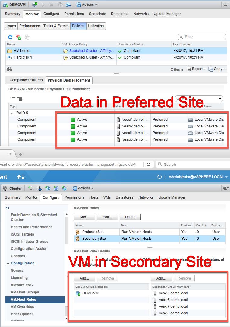
65 65
66 On a local network this may not be a significant issue. In a Stretched Cluster configuration, with sites spread across large geographical distances, this is considered a misconfiguration. This is because when the VM does not run in the same site, reads and writes must traverse the inter-site link. Additional unnecessary bandwidth is consumed to operate the VM running on a site that is opposite to the site the data is stored on. This bandwidth should stay within the same site to ensure lower bandwidth utilization. In the situation where the alternate site is disconnected, the VM will no longer have access to its vmdk and will essentially become a zombie VM. Proper Configuration A proper configuration includes VM/Host Group Rules that properly align with the Affinity Rules assigned to VMs by their corresponding VM Storage Policies. 66

67 Setting proper VM/Host Group Rules and VM Storage Policy Affinity Rules are beneficial for several reasons Bandwidth is not unnecessarily sent across the inter-site link Lower inter-site bandwidth utilization In the situation where the alternate site is disconnected, the VM will continue to have access to its vmdk. Summary It is important to insure proper rules are in place to maintain a properly utilized configuration. VMware recommends VM/Host Group rules along with Affinity rules for VM Storage Policies for VMs that are only being stored on one of the two data sites in a vsan 6.6 Stretched Cluster. 67
68 10. Installation The installation of vsan Stretched Cluster is similar to the configuration of Fault Domains. 68
69 10.1 Installation The installation of vsan Stretched Cluster is almost identical to how Fault Domains were implemented in earlier vsan versions, with a couple of additional steps. This part of the guide will walk the reader through a stretched cluster configuration Before You Start Before delving into the installation of a vsan Stretched Cluster, there are a number of important features to highlight that are specific to stretch cluster environments. What is a Preferred Domain/Preferred Site? Preferred domain/preferred site is simply a directive for vsan. The Preferred site is the site that vsan wishes to remain running when there is a failure and the sites can no longer communicate. One might say that the Preferred" site is the site expected to have the most reliability. Since virtual machines can run on any of the two sites, if network connectivity is lost between site 1 and site 2, but both still have connectivity to the Witness, the preferred site is the one that survives and its components remains active, while the storage on the non-preferred site is marked as down and components on that site are marked as absent. What is Read Locality? Since virtual machines deployed on vsan Stretched Cluster will have compute on one site, but a copy of the data on both sites, vsan will use a read locality algorithm to read 100% from the data copy on the local site, i.e. same site where the compute resides. This is not the regular vsan algorithm, which reads in a round-robin fashion across all replica copies of the data. This new algorithm for vsan Stretched Clusters will reduce the latency incurred on read operations. If latency is less than 5ms and there is enough bandwidth between the sites, read locality could be disabled. However please note that disabling read locality means that the read algorithm reverts to the round robin mechanism, and for vsan Stretched Clusters, 50% of the read requests will be sent to the remote site. This is a significant consideration for sizing of the network bandwidth. Please refer to the sizing of the network bandwidth between the two main sites for more details. The advanced parameter VSAN.DOMOwnerForceWarmCache can be enabled or disabled to change the behavior of read locality. This advanced parameter is hidden and is not visible in the Advanced System Settings vsphere web client. It is only available the CLI. Read locality is enabled by default when vsan Stretched Cluster is configured it should only be disabled under the guidance of VMware s Global Support Services organization, and only when extremely low latency is available across all sites. Witness Host Must not be Part of the vsan Cluster When configuring your vsan stretched cluster, only data hosts must be in the cluster object in vcenter. The witness host must remain outside of the cluster, and must not be added to the cluster at any point. Thus for a configuration, where there is one host at each site and one physical ESXi witness host, the configuration will look similar to the following: 69

70 Note that the witness host is not shaded in blue in this case. The witness host only appears shaded in blue when a vsan Witness Appliance is deployed. Physical hosts that are used as witness hosts are not shaded in blue vsan Health Check Plugin for Stretched Clusters VMware vsan 6.1, shipped with vsphere 6.0U1, has a health check feature built in. This functionality was first available for vsan 6.0. The updated 6.1 version of the health check for vsan has enhancements specifically for vsan stretched cluster. Once the ESXi hosts have been upgraded or installed with ESXi version 6.0U1, there are no additional requirements for enabling the vsan health check. Note that ESXi version 6.0U1 is a requirement for vsan Stretched Cluster. Similarly, once the vcenter Server has been upgraded to version 6.0U1, the vsan Health Check plugin components are also upgraded automatically, provided vsphere DRS is licensed, and DRS Automation is set to Fully Automated. If vsphere DRS is not licensed, or not set to Fully Automated, then hosts will have to be evacuated and the Health Check vsphere Installable Bundle (vib) will have to be installed manually. Please refer to the 6.1 Health Check Guide got additional information. The location is available in the appendix of this guide. New vsan Health Checks for Stretched Cluster Configurations As mentioned, there are new health checks for vsan Stretched Cluster. Select the Cluster object in the vcenter inventory, click on Monitor > vsan > Health. Ensure the stretched cluster health checks pass when the cluster is configured. Note: The stretched cluster checks will not be visible until the stretch cluster configuration is completed. 70
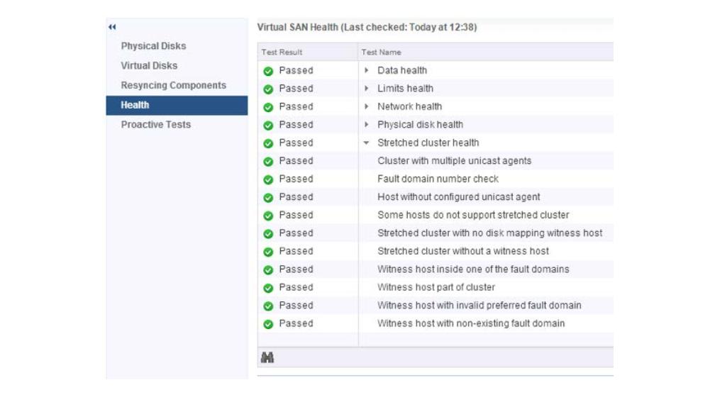
71 71
72 11. Using a vsan Witness Appliance vsan StretchedCluster supports the use of a vsan Witness Appliance 72
73 11.1 Using a vsan Witness Appliance VMware vsan Stretched Cluster supports the use of a vsan Witness Appliance as the Witness host. This is available as an OVA (Open Virtual Appliance) from VMware. However this vsan Witness Appliance needs to reside on a physical ESXi host, which requires some special networking configuration. Networking The vsan Witness Appliance contains two network adapters that are connected to separate vsphere Standard Switches (VSS). The vsan Witness Appliance Management VMkernel is attached to one VSS, and the WitnessPG is attached to the other VSS. The Management VMkernel (vmk0) is used to communicate with the vcenter Server for appliance management. The WitnessPG VMkernel interface (vmk1) is used to communicate with the vsan Network. This is the recommended configuration. These network adapters can be connected to different, or the same, networks, provided they have connectivity to their appropriate services. The Management VMkernel interface could be tagged to include vsan Network traffic as well as Management traffic. In this case, vmk0 would require connectivity to both vcenter Server and the vsan Network. In many nested ESXi environments, there is a recommendation to enable promiscuous mode to allow all Ethernet frames to pass to all VMs that are attached to the port group, even if it is not intended for that particular VM. The reason promiscuous mode is enabled in many nested environments is to prevent a virtual switch from dropping packets for (nested) vmnics that it does not know about on nested ESXi hosts. A Note About Promiscuous Mode In many nested ESXi environments, there is a recommendation to enable promiscuous mode to allow all Ethernet frames to pass to all VMs that are attached to the port group, even if it is not intended for that particular VM. The reason promiscuous mode is enabled in these environments is to prevent a virtual switch from dropping packets for (nested) vmnics that it does not know about on nested ESXi hosts. Nested ESXi deployments are not supported by VMware other than the vsan Witness Appliance. The vsan Witness Appliance is essentially a nested ESXi installation tailored for use with vsan Stretched Clusters and 2 Node vsan clusters. The MAC addresses of the VMkernel interfaces vmk0 & vmk1 are configured to match the MAC addresses of the vsan Witness Appliance host's NICs, vmnic0 and vmnic1. Because of this, packets destined for either the Management VMkernel interface (vmk0) or the WitnessPG VMkernel interface, are not dropped. 73
74 Because of this, promiscuous mode is not required when using a vsan Witness Appliance Setup Step 1: Deploy the vsan Witness Appliance The vsan Witness Appliance must be deployed on different infrastructure than the Stretched Cluster itself. This step will cover deploying the vsan Witness Appliance to a different cluster. The first step is to download and deploy the vsan Witness Appliance, or deploy it directly via a URL, as shown below. In this example it has been downloaded: 74
75 Select a Datacenter for the vsan Witness Appliance to be deployed to and provide a name (Witness-01 or something similar). Select a cluster for the vsan Witness Appliance to reside on. 75
76 Review the details of the deployment and press next to proceed. The license must be accepted to proceed. 76

77 At this point a decision needs to be made regarding the expected size of the Stretched Cluster configuration. There are three options offered. If you expect the number of VMs deployed on the vsan Stretched Cluster to be 10 or fewer, select the Tiny configuration. If you expect to deploy more than 10 VMs, but less than 500 VMs, then the Normal (default option) should be chosen. For more than 500VMs, choose the Large option. On selecting a particular configuration, the resources consumed by the appliance and displayed in the wizard (CPU, Memory and Disk): Select a datastore for the vsan Witness Appliance. This will be one of the datastore available to the underlying physical host. You should consider when the vsan Witness Appliance is deployed as thick 77


78 or thin, as thin VMs may grow over time, so ensure there is enough capacity on the selected datastore. Remember that the vsan Witness Appliance is not supported on vsan Stretched Cluster datastores. Select a network for the Management Network and for the Witness Network. Give a root password for the vsan Witness Appliance: 78

79 At this point, the vsan Witness Appliance is ready to be deployed. It will need to be powered on manually via the vsphere web client UI later: Once the vsan Witness Appliance is deployed and powered on, select it in the vsphere web client UI and begin the next steps in the configuration process Setup Step 2: vsan Witness Appliance Management 79

80 Once the vsan Witness Appliance has been deployed, select it in the vsphere web client UI, open the console. The console of the vsan Witness Appliance should be access to add the correct networking information, such as IP address and DNS, for the management network. On launching the console, unless you have a DHCP server on the management network, it is very likely that the landing page of the DCUI will look something similar to the following: Use the <F2> key to customize the system. The root login and password will need to be provided at this point. This is the root password that was added during the OVA deployment earlier. Select the Network Adapters view. There will be two network adapters, each corresponding to the network adapters on the virtual machine. You should note that the MAC address of the network adapters from the DCUI view match the MAC address of the network adapters from the virtual machine view. Because these match, there is no need to use promiscuous mode on the network, as discussed earlier. Select vmnic0, and if you wish to view further information, select the key <D> to see more details. 80


81 Navigate to the IPv4 Configuration section. This will be using DHCP by default. Select the static option as shown below and add the appropriate IP address, subnet mask and default gateway for this vsan Witness Appliance Management Network. The next step is to configure DNS. A primary DNS server should be added and an optional alternate DNS server can also be added. The FQDN, fully qualified domain name, of the host should also be added at this point. 81


82 One final recommendation is to do a test of the management network. One can also try adding the IP address of the vcenter server at this point just to make sure that it is also reachable. When all the tests have passed, and the FQDN is resolvable, administrators can move onto the next step of the configuration, which is adding the vsan Witness Appliance ESXi instance to the vcenter server Setup Step 3: Add Witness to vcenter Server There is no difference to adding the vsan Witness Appliance ESXi instance to vcenter server when compared to adding physical ESXi hosts. However, there are some interesting items to highlight during the process. First step is to provide the name of the Witness. In this example, vcenter server is managing multiple data centers, so we are adding the host to the witness data center. 82
83 Provide the appropriate credentials. In this example, the root user and password. Acknowledge the certificate warning: 83

84 There should be no virtual machines on the vsan Witness Appliance. Note: It can never run VMs in a vsan Stretched Cluster configuration. Note also the mode: VMware Virtual Platform. Note also that builds number may differ to the one shown here. The vsan Witness Appliance also comes with its own license. You do not need to consume vsphere licenses for the witness appliance: 84

85 Lockdown mode is disabled by default. Depending on the policies in use at a customer s site, the administrator may choose a different mode to the default: Click Finish when ready to complete the addition of the Witness to the vcenter server: 85

86 One final item of note is the appearance of the vsan Witness Appliance ESXi instance in the vcenter inventory. It has a light blue shading, to differentiate it from standard ESXi hosts. It might be a little difficult to see in the screen shot below, but should be clearly visible in your infrastructure. (Note: In vsan 6.1 and 6. 2 deployments, the No datastores have been configured message is because the nested ESXi host has no VMFS datastore. This can be ignored.) 86

87 One final recommendation is to verify that the settings of the vsan Witness Appliance matches the Tiny, Normal or Large configuration selected during deployment. For example, the Normal deployment should have an 12GB HDD for boot in vsan 6.5 (8GB for vsan 6.1/6.2), a 10GB Flash that will be configured later on as a cache device and another 350 HDD that will also be configured later on as a capacity device. Once confirmed, you can proceed to the next step of configuring the vsan network for the vsan Witness Appliance Setup Step 4: Config vsan Witness Host Networking The next step is to configure the vsan network correctly on the vsan Witness Appliance. When the Witness is selected, navigate to Configure > Networking > Virtual switches as shown below. 87
, then the VMkernel adapter will not have a valid IP address.")
88 The Witness has a portgroup pre-defined called witnesspg. Here the VMkernel port to be used for vsan traffic is visible. If there is no DHCP server on the vsan network (which is likely), then the VMkernel adapter will not have a valid IP address. Select VMkernel adapters > vmk1 to view the properties of the witnesspg. Validate that "vsan" is an enabled service as depicted below. 88

89 * Engineering note: A few things to consider when configuring vsan traffic on the vsan Witness Appliance. The default configuration has vmk0 configured for Management Traffic and vmk1 configured for vsan Traffic. The vmk1 interface cannot be configured with an IP address on the same range as that of vmk0. This is because Management traffic and vsan traffic use the default TCP/IP stack. If both vmk0 and vmk1 are configured on the same range, a multihoming condition will occur and vsan traffic will flow from vmk0, rather than vmk1. Health Check reporting will fail because vmk0 does not have vsan enabled. The multihoming issue is detailed in KB ( kb.vmware.com/kb/ ). In the case of 2 Node vsan, If it is desired to have vsan traffic on the same subnet as vmk0, (or simply use a single interface for simplicity), it is recommended to disable vsan services on vmk1 (WitnessPg) and enable vsan services on vmk0 (Management). This is a perfectly valid and supported configuration. Configure the network address Select the witnesspg and edit the properties by selecting the pencil icon. 89

90 If vsan is not an enabled service, select the witnesspg portgroup, and then select the option to edit it. Tag the VMkernel port for vsan traffic, as shown below: Next, ensure the MTU is set to the same value as the Stretched Cluster hosts vsan VMkernel interface. 90
91 In the IPV4 settings, a default IP address has been allocated. Modify it for the vsan traffic network. Static routes are still required by the witnesspg VMkernel interface (vmk1) as in vsan 6.1 or 6.2. The "Override default gateway for this adapter" setting is not supported for the witness VMkernel interface (vmk1). Once the witnesspg VMkernel interface address has been configured, click OK Setup Step 5: Validate Networking 91

92 The final step before a vsan Stretched Cluster can be configured, is to ensure there is connectivity among the hosts in each site and the Witness host. It is important to verify connectivity before attempting to configure vsan Stretched Clusters. Default Gateways and Static Routes By default, traffic destined for the vsan Witness host have no route to the vsan networks from hosts. As a result, pings to the remote vsan networks fail. When using vsan 6.1, 6.2, or 6.5, administrators must implement static routes for the vsan VMkernel interfaces to the Witness Appliance vsan VMkernel interface and vice versa. Static routes, as highlighted previously, tell the TCPIP stack to use a different path to reach a particular network. Now we can tell the TCPIP stack on the data hosts to use a different network path (instead of the default gateway) to reach the vsan network on the witness host. Similarly, we can tell the witness host to use an alternate path to reach the vsan network on the data hosts rather than via the default gateway. Note once again that the vsan network is a stretched L2 broadcast domain between the data sites as per VMware recommendations, but L3 is required to reach the vsan network of the witness appliance. Therefore, static routes are needed between the data hosts and the witness host for the vsan network, but they are not required for the data hosts on different sites to communicate to each other over the vsan network. Hosts in Site A Looking at host esxi01-sitea.rainpole.com, initially there is no route from the vsan VMkernel interface (vmk1) to the vsan Witness Appliance vsan VMkernel interface with the address of Notice that when attempting to ping the vsan Witness Appliance from host esxi01- sitea.rainpole.com's vsan VMkernel interface (vmk1), there is no communication. The command vmkping -I vmk1 <target IP> uses vmk1, because the -I switch specifies using the vmk1 interface. 92

93 Add a static route for each host. The esxcli commands used to add a static route is: esxcli network ip route ipv4 add n <remote network> -g <gateway to use> For the hosts in Site A, the command used above is esxcli network ip route ipv4 add -n /24 - g This is because the hosts in Site A, have a gateway to the Witness vsan Appliance vsan VMkernel interface through Other useful commands are esxcfg-route n, which will display the network neighbors on various interfaces, and esxcli network ip route ipv4 list, to display gateways for various networks. Make sure this step is repeated for all hosts. Hosts in Site B Looking at esxi02-siteb.rainpole.com, it can also be seen that there is no route to the vsan VMkernel Interface (vmk1) to the vsan Witness Appliance VMkernel interface with the address The issue is the same as esxi01-sitea.rainpole.com on esxi02-siteb.rainpole.com. The route from Site B to the vsan Witness Appliance vsan VMkernel interface, is different however. The route from Site B (in this example) is through For the hosts in Site B, the command used above is esxcli network ip route ipv4 add -n /24 - g The vsan Witness Appliance in the 3rd Site The vsan Witness Appliance, in the 3rd Site is configured a bit different. The vsan VMkernel interface (vmk1) must communicate across different gateways to connect to Site A and Site B. Communication to Site A in this example must use and communication to Site B must use

94 Because of this routes must be added for each vsan VMkernel interface for each of the hosts in Site A and Site B, on the vsan Witness Appliance. To do this individually for each host in Site A, the commands would be: esxcli network ip route ipv4 add -n /32 -g esxcli network ip route ipv4 add -n /32 -g To do this individually for each host in Site B, the commands would be: esxcli network ip route ipv4 add -n /32 -g esxcli network ip route ipv4 add -n /32 -g With proper routing for each site, connectivity can be verified. Before verifying, let's review the configuration. Configuration Summary The following illustration shows the data flow between each of the data sites and the vsan Witness Appliance in Site 3. 94


95 Host VMkernel IP Site Static Route to Witness Static Route to Site A Static Route to Site B Fau Doma esxi01- sitea.rainpole.com vmk A NA NA Prefer esxi02- sitea.rainpole.com vmk A NA NA Prefer esxi01- siteb.rainpole.com vmk B NA NA Second esxi02- siteb.rainpole.com vmk B NA NA Second witness-01.rainpole.com vmk NA Node vsan Configurations With 2 Node vsan configurations, each node behaves as a site. With both "sites" being in the same location, they are likely behind the same router and it is not necessary to have a different default gateway for Host 1 and Host 2. 95

96 A conventional vsan 2 Node configuration will look something like this: Conventional vsan 2 Node Configuration Host VMkernel IP Traffic Type Site Static Route to Witness Static Route to Host 1 Static Route to Host 2 host1-2node.rainpole.com vmk vsan A NA NA host2-2node.rainpole.com vmk vsan A NA NA witness-01.rainpole.com vmk vsan 3 NA A DirectConnect vsan 2 Node Configuration is a little different. An alternate VMkernel port will be used to communicate with the vsan Witness Appliance. This is because the vsan data network will be directly connected between hosts. It will look something like this: 96

97 The 2 Node Direct Connect configuration will have the following connectivity (with vmk0 set for Witness Traffic) Host VMkernel IP Traffic Type Site Static Route to Witness Static Route to Host 1 Static Route to Host 2 host1-2node.rainpole.com vmk Witness A NA NA host2-2node.rainpole.com vmk Witness A NA NA witness-01.rainpole.com vmk vsan 3 NA With 2 Node vsan Configurations, routing and connectivity will be dependent on choosing a conventional or Direct Connect design. Next Steps Once routing is in place, ping from each host's appropriate interface using vmkping -I vmkx <destination IP> to check connectivity. When connectivity has been verified between the vsan data node VMkernel interfaces and the vsan Witness Appliance vsan VMkernel interface, the Stretched (or 2 Node) Cluster can be configured. 97
98 12. Configuring vsan Stretched Cluster There are two methods to configure a vsan Stretched Cluster. 98
99 12.1 Configuring vsan Stretched Cluster There are two methods to configure a vsan Stretched Cluster. A new cluster can be stretched or an existing cluster can be converted to a Stretched Cluster Creating a New vsan Stretched Cluster Creating a vsan stretched cluster from a group of hosts that does not already have vsan configured is relatively simple. A new vsan cluster wizard makes the process very easy. Create Step 1: Create a Cluster The following steps should be followed to install a new vsan stretched cluster. This example is a deployment, meaning three ESXi hosts at the preferred site, three ESXi hosts at the secondary site and 1 witness host. In this example, there are 6 nodes available: esx01-sitea, esx02-site a, esx03-sitea, esx01-siteb, esx02- siteb, and esx03-siteb. All six hosts reside in a vsphere cluster called stretched-vsan. The seventh host witness-01, which is the witness host, is in its own data center and is not added to the cluster. To setup vsan and configure stretch cluster navigate to the Manage > vsan > General. Click Configure to begin the vsan wizard. Create Step 2 Configure vsan as a Stretched Cluster The initial wizard allows for choosing various options like disk claiming method, enabling Deduplication and Compression (All-Flash architectures only with Advanced or greater licensing), as 99


100 well as configuring fault domains or stretched cluster. Click Configure stretched cluster. Create Step 3 Validate Network Network validation will confirm that each host has a VMkernel interface with vsan traffic enabled. Click Next. Create Step 4 Claim Disks If the Claim Disks was set to Manual, disks should be selected for their appropriate role in the vsan cluster. 100

101 Click Next. Create Step 5 Create Fault Domains The Create fault domain wizard will allow hosts to be selected for either of the two sides of the stretched cluster. The default naming of these two fault domains are Preferred and Secondary. These two fault domains will behave as two distinct sites. 101


102 Click Next. Create Step 6 Select Witness Host The Witness host detailed earlier must be selected to act as the witness to the two fault domains. Click Next. 102


103 Create Step 7 Claim Disks for Witness Host Just like physical vsan hosts, the witness needs a cache tier and a capacity tier. *Note: The witness does not actually require SSD backing and may reside on a traditional mechanical drive. Select Next. Create Step 8 Complete Review the vsan Stretched Cluster configuration for accuracy and click Finish Converting a Cluster to a Stretched Cluster The following steps should be followed to convert an existing vsan cluster to a stretched cluster. This example is a deployment, meaning three ESXi hosts at the preferred site, three ESXi hosts at the secondary site and 1 witness host. Consider that all hosts are properly configured and vsan is already up and running. 103


104 Convert Step 1 Fault Domains & Stretched Cluster Configuring fault domains and stretched cluster setting is handled through the Fault Domains & Stretched Cluster menu item. Select Manage > Settings > Fault Domains & Stretched Cluster. Convert Step 2 Selecting Hosts to Participate Select each of the hosts in the cluster and click Configure. 104


105 Convert Step 3 Configure Fault Domains The Create fault domain wizard will allow hosts to be selected for either of the two sides of the stretched cluster. The default naming of these two fault domains are Preferred and Secondary. These two fault domains will behave as two distinct sites. Convert Step 4 Select a Witness Host The Witness host detailed earlier must be selected to act as the witness to the two fault domains. Convert Step 5 Claim Disks for Witness Host Just like physical vsan hosts, the witness needs a cache tier and a capacity tier. *Note: The witness does not actually require SSD backing and may reside on a traditional mechanical drive. 105

106 Convert Step 6 Complete Review the vsan Stretched Cluster configuration for accuracy and click Finish Configure Stretched Cluster Site Affinity Configure Step 1 Create Host Groups At this point, there needs to be a way of specifying which site a VM should be deployed to. This is achieved with VM Groups, Host Groups and VM/Host Rules. With these groups and rules, and administrator can specify which set of hosts (i.e. which site) a virtual machine is deployed to. The first step is to create two host groups; the first host groups will contain the ESXi hosts from the preferred site whilst the second host group will contain the ESXi host from the secondary site. In this setup example, a environment is being deployed, so there are two hosts in each host group. Select the cluster object from the vsphere Inventory, select Manage, then Settings. This is where the VM/Host Groups are created. Navigate to cluster > Manage > VM/Host Groups. Select the option to add a group. Give the group a name, and ensure the group type is Host Group as opposed to VM Group. Next, click Add to select 106

107 the hosts should be in the host group. Select the hosts from site A. Once the hosts have been added to the Host Group, click OK. Review the settings of the host group, and click OK once more to create it: This step will need to be repeated for the secondary site. Create a host group for the secondary site and add the ESXi hosts from the secondary site to the host group. 107
108 When hosts groups for both data sites have been created, the next step is to create VM groups. However, before you can do this, virtual machines should be created on the cluster. Configure Step 2: Create VM Groups Once the host groups are created, the initial set of virtual machines should now be created. Do not power on the virtual machines just yet. Once the virtual machines are in the inventory, you can now proceed with the creation of the VM Groups. First create the VM Group for the preferred site. Select the virtual machines that you want for the preferred site. In the same way that a second host group had to be created previously for the secondary site, a secondary VM Group must be created for the virtual machines that should reside on the secondary site. Configure Step 3: Create VM/Host Rules Now that the host groups and VM groups are created, it is time to associate VM groups with host groups and ensure that particular VMs run on a particular site. Navigate to the VM/Host rules to associate a VM group with a host group. In the example shown below, The VMs in the sec-vms VM group with the host group called site-bhostgroup, which will run the virtual machines in that group on the hosts in the secondary site. 108


109 One item highlighted above is that this is a should rule. We use a should rule as it allows vsphere HA to start the virtual machines on the other side of the stretched cluster in the event of a site failure. Another VM/Host rule must be created for the primary site. Again this should be a "should rule. Please note that DRS will be required to enforce the VM/Host Rules. Without DRS enabled, the soft should rules have no effect on placement behavior in the cluster. Configure Step 4: Set vsphere HA Rules There is one final setting that needs to be placed on the VM/Host Rules. This setting once again defines how vsphere HA will behave when there is a complete site failure. In the screenshot below, there is a section in the VM/Host rules called vsphere HA Rule Settings. One of the settings is for VM to Host Affinity rules. A final step is to edit this from the default of ignore and change it to vsphere HA should respect VM/Host affinity rules as shown below: This setting can be interpreted as follows: If there are multiple hosts on either sites, and one hosts fails, vsphere HA will try to restart the VM on the remaining hosts on that site, maintained read affinity. If there is a complete site failure, then vsphere HA will try to restart the virtual machines on the hosts on the other site. If the must respect option shown above is selected, then vsphere HA 109
: Set VM Storage Policy Affinity Rules When using vsan 6.6, it may be desired to store a VM's data only on the site the VM runs on.")
110 would be unable to restart the virtual machines on the other site as it would break the rule. Using a should rule allows it to do just that. Configure Step 5 (Optional): Set VM Storage Policy Affinity Rules When using vsan 6.6, it may be desired to store a VM's data only on the site the VM runs on. To accomplish this, a VM storage policy with the Affinity Rule must be created. Rules should be selected as follows: Primary level of failures to tolerate (PFTT) = 0 - This ensures the Affinity Rule may be used Secondary level of failures to tolerate (SFTT) = 0,1,2,3 - Based on Failure Tolerance Method desired for local protection Failure tolerance method = Mirroring or Erasure Coding - This is based on the desired protection method. All-Flash is required for Erasure Coding. Affinity - Preferred or Secondary Fault Domain - This will align with VM/Host Group Rules VMware recommends that when using Site Affinity for vsan object placement, VM/Host Group Rules should be aligned accordingly. More information specific to Per-Site Polices and Affinity may be found here: storagehub.vmware.com/#!/vmware-vsan/vsan-stretched-cluster-2-node-guide/per-site-policies/ Verifying vsan Stretched Cluster Component Layouts That completes the setup of the vsan Stretched Cluster. The final steps are to power up the virtual machines created earlier, and examine the component layout. When NumberOfFailuresToTolerate = 1 is chosen, a copy of the data should go to both sites, and the witness should be placed on the witness host. In the example below, esx01-sitea and esx02-sitea resides on site 1, whilst esx01-siteb and esx02- siteb resides on site 2. The host witness-01 is the witness. The layout shows that the VM has been 110

111 deployed correctly. As we can clearly see, one copy of the data resides on storage in site1, a second copy of the data resides on storage in site2 and the witness component resides on the witness host and storage on the witness site. Everything is working as expected. Warning: Disabling and re-enabling of vsan in a stretched cluster environment has the following behaviors: The witness configuration is not persisted. When recreating a stretched cluster vsan, the witness will need to be re-configured. If you are using the same witness disk as before, the disk group will need to be deleted. This can only be done by opening an SSH session to the ESXi host, logging in as a privileged user and removing the disk group with the esxcli vsan storage remove command. The fault domains are persisted, but vsan does not know which FD is the preferred one. Therefore, under Fault Domains, the secondary FD will need to be moved to the secondary column as per of the reconfiguration Upgrading a older vsan Stretched Cluster Upgrading a vsan Stretched Cluster is very easy. It is important though to follow a sequence of steps to ensure the upgrade goes smoothly. Upgrading Step 1: Upgrade vcenter Server As with any vsphere upgrades, it is typically recommended to upgrade vcenter Server first. While vcenter Server for Windows installations are supported, the steps below describe the process when using the vcenter Server Appliance (VCSA). 111


112 Log in to the VAM I interface and select Update from the Navigator pane to begin the upgrade process. *Refer to the documentation for vcenter Server for Windows to properly upgrade to a newer release of vcenter Server. After the upgrade has completed, the VCSA will have to be rebooted for the updates to be applied. It is important to remember that vsan Health Check will not be available until after hosts have been upgraded. Upgrading Step 2: Upgrade Hosts in Each Site Upgrading hosts at each site is the next task to be completed. There are a few considerations to remember when performing these steps. As with any upgrade, hosts will be required to be put in maintenance mode, remediated, upgraded, and rebooted. It is important to consider the amount of available capacity at each site. In sites that have sufficient available capacity, it would be desirable to choose the full data migration vsan data migration method. This method is preferred when site locality is important for read operations. When the ensure accessibility method is selected, read operations will traverse the inter-site link. Some applications may be more sensitive to the additional time required to read data from the alternate site. With vsphere DRS in place, as hosts are put in maintenance mode, it is important to ensure the previously described VM/host groups and VM/host rules are in place. These rules will ensure that virtual machines are moved to another host in the same site. If DRS is set to fully automated virtual machines will vmotion to other hosts automatically, while partially automated or manual will require the virtualization admin to vmotion the virtual machines to other hosts manually. It is recommended to sequentially upgrade hosts at each site first, followed by sequentially upgrading the hosts at the alternate site. This method will introduce the least amount of additional storage 112


113 traffic. While it is feasible to upgrade multiple hosts simultaneously across sites when there is additional capacity, as data is migrated within each site, this method will require additional resources. Upgrading Step 3: Upgrade the Witness Appliance After both data sites have been upgraded, the witness will also need to be upgraded. The Health Check will show that the witness has not been upgraded. Upgrading the witness is done in the same way that physical ESXi hosts are updated. It is important to remember that before the witness is upgraded, the witness components will no longer be available and objects will be noncompliant. Objects will report that the witness component is not found. After the upgrade is complete, the witness component will return, and will reside on the witness. 113

114 Upgrading Step 4: Upgrade the on-disk Format if necessary The final step in the upgrade process, will be to upgrade the on-disk format. To use the new features introduced in vsan 6.2 like deduplication and compression or checksum, the on-disk format must be upgraded to version 3.0. The Health Check will assuming that vsphere 6.0 Update 2 or higher hosts would prefer a version 3.0 on-disk format, and as a result, it will throw an error until the format is upgraded. To upgrade the on-disk format from version 2.0 to version 3.0, select Manage > General under vsan. Then click Upgrade under the On-disk Format Version section. The on-disk format upgrade will perform a rolling upgrade across the hosts in the cluster within each site. Each host s disk groups will be removed and recreated with the new on-disk format. The amount of time required to complete the on-disk upgrade will vary based on the cluster hardware configuration, how much data is on the cluster, and whatever over disk operations are occurring on the cluster. The on-disk rolling upgrade process does not interrupt virtual machine disk access and is performed automatically across the cluster. The witness components residing on the witness appliance will be deleted and recreated. This process is relatively quick given the size of witness objects. Once the on-disk format is complete, the cluster has been upgraded. 114
115 115
116 13. Management and Maintenance The following section of the guide covers considerations related to management and maintenance of a vsan Stretched Cluster configuration. 116
117 13.1 Management and Maintenance The following section of the guide covers considerations related to management and maintenance of a vsan Stretched Cluster configuration Maintenance Mode Consideration When it comes to maintenance mode in the vsan Stretched Cluster configuration, there are two scenarios to consider; maintenance mode on a site host and maintenance mode on the witness host. Maintenance Mode on a Site Host Maintenance mode in vsan Stretched Clusters is site specific. All maintenance modes (Ensure Accessibility, Full data migration and No data migration) are all supported. However, in order to do a Full data migration, you will need to ensure that there are enough resources in the same site to facilitate the rebuilding of components on the remaining node on that site. Maintenance Mode on the Witness Host Maintenance mode on the witness host should be an infrequent event, as it does not run any virtual machines. When maintenance mode is performed on the witness host, the witness components cannot be moved to either site. When the witness host is put in maintenance mode, it behaves as the No data migration option would on site hosts. It is recommended to check that all virtual machines are in compliance and there is no ongoing failure, before doing maintenance on the witness host. 117
118 14. Failure Scenarios In this section, we will discuss the behavior of the vsan Stretched Cluster when various failures occur. 118

119 14.1 Failure Scenarios Failure Scenarios and Component Placement Understanding component placement is paramount in understanding failure scenarios. The illustration shows the the placement of a vsan Object's components in a Stretched Cluster Scenario. The virtual machine's virtual disk (vmdk) has one component placed in the Preferred Site, one component placed in the Secondary Site, and a Witness component in the Tertiary Site that houses the vsan Witness Host. The illustration shows a storage policy that will protect across sites, but not within a site. This is the default protection policy used with vsan Stretched Clusters for versions 6.1 through 6.5. Local protection within a site was added in vsan 6.6. Below is a vsan 6.6 cluster with data protection (mirroring) across sites, as well as local data protection (mirroring in this case) within each of the data sites. vsan Stretched Clusters can support up to a single complete site failure and a policy based maximum of host failures within a site. 119
120 If a site has more failures than the local protection policy will allow, then the site is considered failed. It is important to remember that the vsan Witness Host, residing in the Tertiary site, is only a single host. Because of this, a failure of the vsan Witness Host is also considered a site failure. The scenarios in this section will cover different failure behaviors Individual Host Failure or Network Isolation What happens when a host fails or is network isolated? vsan will mark the component absent. The VM will continue to run or it will be rebooted by vsphere HA if the VM was running on the host that went offline. If the policy includes Local Protection (introduced in vsan 6.6), reads will be serviced by the remaining components within the same site. The component will be rebuilt within the same site after 60 minutes if there is an additional host available and the failed host does not come back online. If there are no additional hosts available within the site, the component will only be rebuilt if the failed/isolated host comes back online. In cases where multiple hosts that contain the components fail or are isolated, reads will be services across the inter-site link. This can be a significant amount of traffic on the inter-site link depending on the amount of data on the failed host. If the policy does not include Local Protection, reads will be serviced across the inter-site link. This can be a significant amount of traffic on the inter-site link depending on the amount of data on the failed host. The component will be rebuilt within the same site as the failed/isolated hosts after 60 minutes if there is an alternate 120
121 If there are no additional hosts available, or hosts are at capacity, the component will only be rebuilt if the failed/isolated host comes back online Individual Drive Failure What happens when a drive fails? vsan will mark the component absent. The VM will continue to run. If the policy includes Local Protection (introduced in vsan 6.6), reads will be serviced by the remaining components within the same site. The component will be rebuilt within the same site after 60 minutes if there is an additional host available and the failed host does not come back online. If there are no additional hosts available within the site, the component will only be rebuilt if the failed/isolated host comes back online. In cases where multiple hosts that contain the components fail or are isolated, reads will be services across the inter-site link. This can be a significant amount of traffic on the inter-site link depending on the amount of data on the failed host. 121
122 If the policy does not include Local Protection, reads will be serviced across the inter-site link. This can be a significant amount of traffic on the inter-site link depending on the amount of data on the failed host. The component will be rebuilt within the same site as the failed/isolated hosts after 60 minutes if there is an alternate If there are no additional hosts available, or hosts are at capacity, the component will only be rebuilt if the failed/isolated host comes back online Site Failure or Network Partitions What happens when sites go offline, or lose connectivity? A typical vsan Stretched Cluster configuration can be seen here: 122
123 Preferred Site Failure or Completely Partitioned In the event the Preferred Site fails or is partitioned, vsan powers the virtual machines running in that site off. The reason for this, is because the virtual machine's components are not accessible due to the loss of quorum. The vsan Stretched Cluster has now experienced a single site failure. The loss of either site in addition to the witness is two failures, will take the entire cluster offline. 123
124 An HA master node will be elected in the Secondary Site, which will validate which virtual machines are to be powered on. Because quorum has been formed between the vsan Witness Host and the Secondary Site, virtual machines in the Secondary Site will have access to their data, and can be powered on. 124
125 Secondary Site Failure or Partitioned In the event the Secondary Site fails or is partitioned, vsan powers the virtual machines running in that site off. The reason for this, is because the virtual machine's components are not accessible due to the loss of quorum. The vsan Stretched Cluster has now experienced a single site failure. The loss of either site in addition to the witness is two failures, will take the entire cluster offline. 125
126 The HA Master on the Preferred Site, will validate which virtual machines are to be powered on. Virtual machines which have been moved to the Preferred Site will now have access to their data, and can be powered on. 126
127 vsan Witness Host Failure or Partitioned Virtual machines running in both of the main sites of a Stretched Cluster are not impacted by the vsan Witness Host being partitioned. Virtual machines continue to run at both locations. The vsan Stretched Cluster has now experienced a single site failure. The loss of either site in addition to the witness is two failures, will take the entire cluster offline. 127
128 In the event the vsan Witness Host has failed, the behavior is the same as if the vsan Witness Hosts were partitioned from the cluster. Virtual machines continue to run at both locations. Because the vsan Stretched Cluster has now experienced a single site failure, it is important to either get the vsan Witness Host back online, or deploy a new one for the cluster. 128

129 When the existing vsan Witness Host comes back online or a new vsan Witness Host is deployed, metadata changes are resynchronized between the main Stretched Cluster sites and the vsan Witness Host. The amount of data that needs to be transmitted depends on a few items such as the number of objects and the number of changes that occurred while the vsan Witness Host was offline. However, this amount of data is relatively small considering it is metadata, not large objects such as virtual disks. 129
130 14.5 Multiple Simultaneous Failures What happens if there are failures at multiple levels? The scenarios thus far have only covered situations where a single failure has occurred. Local Protection in was introduced in vsan 6.6. Reviewing the vsan Storage Policy Rule changes, Number of Failures to Tolerate became Primary Number of Failures to Tolerate, and is directly associated with site availability. Secondary Number of Failures to Tolerate was introduced with Local Protection, which works along with Failure Tolerance Method to determine data layout/placement within a Stretched Cluster site. Votes and their contribution to object accessibility The vsan Design and Sizing Guide goes into further detail about how component availability determines access to objects. In short, each component has a vote, and a quorum of votes must be present for an object to be accessible. Each site will have an equal number of votes and there will be an even distribution of votes within a site. If the total number of votes is an even number, a random vote will be added. 130

131 In the illustration below, an 8 Node vsan Stretched Cluster (4+4+1) has an object with PFTT=1 (Mirrored across sites) and SFTT=1/FTM Mirroring (Local Protection). Each site has 3 votes each in this case, with a total of 9 votes. If the vsan Witness Host fails, 3 votes are no longer present, leaving only 6 accessible. Only 66% of the components are available, so the vmdk is still accessible. With the loss of a vsan Disk, 4 votes are no longer present, leaving only 5 accessible. Because 55.5% of the components are available, the vmdk is still accessible. 131
132 If a component in another location, on either site, regardless of having Local Protection enabled, were to fail, the vmdk would be inaccessible. Below, the illustration shows the vsan Witness Host offline, 1 failure in the Preferred Site, and 1 failure in the Secondary Site. In this illustration, the vsan Witness Host offline and 2 failures in the Preferred Site. 132
133 In both cases, only 44.4% of the votes are present (4 of 9), resulting in the virtual machine's vmdk being inaccessible. It is important to understand that components, the weight of their votes, and their presence/absence determine accessibility of the vsan object. In each of the above failure cases, restoring access to the existing vsan Witness would make the object accessible. Deploying a new vsan Witness would not because the components would not be present Recovering from a Complete Site Failure The descriptions of the host failures previously, although related to a single host failure, are also complete site failures. VMware has modified some of the vsan behavior when a site failure occurs and subsequently recovers. In the event of a site failure, vsan will now wait for some additional time for all hosts to become ready on the failed site before it starts to sync components. The main reason is that if only some subset of the hosts come up on the recovering site, then vsan will start the rebuild process. This may result in the transfer of a lot of data that already exists on the nodes that might become available at some point in time later on. VMware recommends that when recovering from a failure, especially a site failure, all nodes in the site should be brought back online together to avoid costly resync and reconfiguration overheads. The reason behind this is that if vsan bring nodes back up at approximately the same time, then it will only need to synchronize the data that was written between the time when the failure occurred and the when the site came back. If instead nodes are brought back up in a staggered fashion, objects might to be reconfigured and thus a significant higher amount of data will need to be transferred between sites How Read Locality is Established After Failover How Read Locality is Established After Failover to Other Site? A common question is how read locality is maintained when there is a failover. This guide has already described read locality, and how in a typical vsan deployment, a virtual machine reads equally from all 133
134 of its replicas in a round-robin format. In other words, if a virtual machine has two replicas as a result of being configured to tolerate one failure, 50% of the reads come from each replica. This algorithm has been enhanced for Stretched Clusters so that 100% of the reads comes from vsan hosts on the local site, and the virtual machine does not read from the replica on the remote site. This avoids any latency that might be incurred by reading over the link to the remote site. The result of this behavior is that the data blocks for the virtual machine are also cached on the local site. In the event of a failure or maintenance event, the virtual machine is restarted on the remote site. The 100% rule continues in the event of a failure. This means that the virtual machine will now read from the replica on the site to which it has failed over. One consideration is that there is no cached data on this site, so cache will need to warm for the virtual machine to achieve its previous levels of performance. New for vsan 6.6, when a Site Affinity rule is used in conjunction with a PFTT=0 policy, data is not present on the alternate site. When the virtual machine starts on the other site, either as part of a vmotion operation or a power on from vsphere HA restarting it, vsan instantiates the in-memory state for all the objects of said virtual machine on the host where it moved. That includes the owner (coordinator) logic for each object. The owner checks if the cluster is setup in a stretch cluster mode, and if so, which fault domain it is running in. It then uses the different read protocol instead of the default round-robin protocol across replicas (at the granularity of 1MB), it sends 100% of the reads to the replica that is on the same site (but not necessarily the same host) as the virtual machine Replacing a Failed Witness Host Should a vsan Witness Host fail in the vsan Stretched Cluster, a new vsan Witness Host can easily be introduced to the configuration. Swapping out the vsan Witness Host Pre-6.6 Navigate to Cluster > Manage > vsan > Fault Domains. The failing witness host can be removed from the vsan Stretched Cluster via the UI (red X in fault domains view). 134


 timer expires after a default of 60 minutes, witness components will be rebuilt on new witness host.")
135 The next step is to rebuild the vsan stretched and selecting the new witness host. In the same view, click on the configure stretched cluster icon. Align hosts to the preferred and secondary sites as before. This is quite simple to do since the hosts are still in the original fault domain, so simply select the secondary fault domain and move all the hosts over in a single click: Select the new witness host: Create the disk group and complete the vsan Stretched Cluster creation. On completion, verify that the health check failures have resolved. Note that the vsan Object health test will continue to fail as the witness component of VM still remains Absent. When CLOMD (Cluster Level Object Manager Daemon) timer expires after a default of 60 minutes, witness components will be rebuilt on new witness host. Rerun the health check tests and they should all pass at this point, and all witness components should show as active VM Provisioning When a Site is Down If there is a failure in the cluster, i.e. one of the sites is down; new virtual machines can still be provisioned. The provisioning wizard will however warn the administrator that the virtual machine does 135
DELL EMC VxRAIL vsan STRETCHED CLUSTERS PLANNING GUIDE
 WHITE PAPER - DELL EMC VxRAIL vsan STRETCHED CLUSTERS PLANNING GUIDE ABSTRACT This planning guide provides best practices and requirements for using stretched clusters with VxRail appliances. April 2018
Disclaimer This presentation may contain product features that are currently under development. This overview of new technology represents no commitme
 STO1926BU A Day in the Life of a VSAN I/O Diving in to the I/O Flow of vsan John Nicholson (@lost_signal) Pete Koehler (@vmpete) VMworld 2017 Content: Not for publication #VMworld #STO1926BU Disclaimer
Administering VMware Virtual SAN. Modified on October 4, 2017 VMware vsphere 6.0 VMware vsan 6.2
 Administering VMware Virtual SAN Modified on October 4, 2017 VMware vsphere 6.0 VMware vsan 6.2 You can find the most up-to-date technical documentation on the VMware website at: https://docs.vmware.com/
Administering VMware vsan. 17 APR 2018 VMware vsphere 6.7 VMware vsan 6.7
 Administering VMware vsan 17 APR 2018 VMware vsphere 6.7 VMware vsan 6.7 You can find the most up-to-date technical documentation on the VMware website at: https://docs.vmware.com/ If you have comments
vsan Planning and Deployment Update 1 16 OCT 2018 VMware vsphere 6.7 VMware vsan 6.7
 vsan Planning and Deployment Update 1 16 OCT 2018 VMware vsphere 6.7 VMware vsan 6.7 You can find the most up-to-date technical documentation on the VMware website at: https://docs.vmware.com/ If you have
VMware vsan 6.7 Technical Overview First Published On: Last Updated On:
 VMware vsan 6.7 Technical Overview First Published On: 04-17-2018 Last Updated On: 04-27-2018 1 Table of Contents 1. Introduction 1.1.Enterprise-Class Storage for HCI 2. Architecture 2.1.Servers with Local
Administering VMware vsan. Modified on October 4, 2017 VMware vsphere 6.5 VMware vsan 6.6.1
 Administering VMware vsan Modified on October 4, 2017 VMware vsphere 6.5 VMware vsan 6.6.1 You can find the most up-to-date technical documentation on the VMware website at: https://docs.vmware.com/ If
vsan Stretched Cluster Bandwidth Sizing First Published On: Last Updated On:
 vsan Stretched Cluster Bandwidth Sizing First Published On: 07-20-2016 Last Updated On: 11-22-2017 1 Table of Contents 1. VSAN Stretched Cluster 1.1.Overview 1.2.General Guidelines 1.3.Bandwidth Requirements
vsan Stretched Cluster Configuration First Published On: Last Updated On:
 vsan Stretched Cluster Configuration First Published On: 11-07-2016 Last Updated On: 01-25-2017 1 Table of Contents 1. Stretched Cluster Configuration 1.1.Stretched Cluster Topology and Configuration 1.2.vSAN
Disclaimer This presentation may contain product features that are currently under development. This overview of new technology represents no commitme
 STO1193BU A Closer Look at vsan Networking Design and Configuration Considerations Cormac Hogan Andreas Scherr VMworld 2017 Content: Not for publication #VMworld #STO1193BU Disclaimer This presentation
Running VMware vsan Witness Appliance in VMware vcloudair First Published On: April 26, 2017 Last Updated On: April 26, 2017
 Running VMware vsan Witness Appliance in VMware vcloudair First Published On: April 26, 2017 Last Updated On: April 26, 2017 1 Table of Contents 1. Executive Summary 1.1.Business Case 1.2.Solution Overview
vsan All Flash Features First Published On: Last Updated On:
 First Published On: 11-07-2016 Last Updated On: 11-07-2016 1 1. vsan All Flash Features 1.1.Deduplication and Compression 1.2.RAID-5/RAID-6 Erasure Coding Table of Contents 2 1. vsan All Flash Features
VMware Virtual SAN. Technical Walkthrough. Massimiliano Moschini Brand Specialist VCI - vexpert VMware Inc. All rights reserved.
 VMware Virtual SAN Technical Walkthrough Massimiliano Moschini Brand Specialist VCI - vexpert 2014 VMware Inc. All rights reserved. VMware Storage Innovations VI 3.x VMFS Snapshots Storage vmotion NAS
vsan Remote Office Deployment January 09, 2018
 January 09, 2018 1 1. vsan Remote Office Deployment 1.1.Solution Overview Table of Contents 2 1. vsan Remote Office Deployment 3 1.1 Solution Overview Native vsphere Storage for Remote and Branch Offices
Native vsphere Storage for Remote and Branch Offices
 SOLUTION OVERVIEW VMware vsan Remote Office Deployment Native vsphere Storage for Remote and Branch Offices VMware vsan is the industry-leading software powering Hyper-Converged Infrastructure (HCI) solutions.
Intelligent Rebuilds in vsan 6.6 January 08, 2018
 January 08, 2018 1 Table of Contents 1. Introduction 1.1.Executive Summary 1.2.Introduction to Intelligent Rebuilds 2. vsan 6.6 Intelligent Rebuilds 2.1.Purpose of Intelligent Rebuilds 2.2.Intelligent
Disclaimer This presentation may contain product features that are currently under development. This overview of new technology represents no commitme
 STO1297BE Stretched Clusters or VMware Site Recovery Manager? We Say Both! Jeff Hunter, VMware, @jhuntervmware GS Khalsa, VMware, @gurusimran #VMworld Disclaimer This presentation may contain product features
VMware vsan Design and Sizing Guide First Published On: February 21, 2017 Last Updated On: April 04, 2018
 VMware vsan Design and Sizing Guide First Published On: February 21, 2017 Last Updated On: April 04, 2018 1 Table of Contents 1. Introduction 1.1.Overview 2. vsan Design Overview 2.1.Adhere to the VMware
Leveraging VMware vsan for Highly Available Management Clusters
 VMware vcloud Architecture Toolkit for Service Providers Leveraging VMware vsan for Highly Available Management Clusters Version 2.9 January 2018 Danilo Feroce 2018 VMware, Inc. All rights reserved. This
Table of Contents HOL HCI
 Table of Contents Lab Overview - - vsan v6.6.1 - Getting Started... 2 Lab Guidance... 3 Module 1 - vsan 6.6.1 Setup and Enablement (15 Minutes,Beginner)... 9 Introduction... 10 VMware vsan Overview...
VMware vsan 6.6 Technical Overview First Published On: Last Updated On:
 VMware vsan 6.6 Technical Overview First Published On: 04-11-2017 Last Updated On: 02-09-2018 1 Table of Contents 1. Introduction 1.1.Enterprise-Class Storage for HCI 2. Architecture 2.1.Servers with Local
VMWARE VSAN LICENSING GUIDE - MARCH 2018 VMWARE VSAN 6.6. Licensing Guide
 - MARCH 2018 VMWARE VSAN 6.6 Licensing Guide Table of Contents Introduction 3 License Editions 4 Virtual Desktop Infrastructure... 5 Upgrades... 5 Remote Office / Branch Office... 5 Stretched Cluster with
vsan Disaster Recovery November 19, 2017
 November 19, 2017 1 Table of Contents 1. Disaster Recovery 1.1.Overview 1.2.vSAN Stretched Clusters and Site Recovery Manager 1.3.vSAN Performance 1.4.Summary 2 1. Disaster Recovery According to the United
2014 VMware Inc. All rights reserved.
 2014 VMware Inc. All rights reserved. Agenda Virtual SAN 1 Why VSAN Software Defined Storage 2 Introducing Virtual SAN 3 Hardware Requirements 4 DEMO 5 Questions 2 The Software-Defined Data Center Expand
Microsoft SQL Server 2014 on VMware vsan 6.2 All-Flash October 31, 2017
 Microsoft SQL Server 2014 on VMware vsan 6.2 All-Flash October 31, 2017 1 Table of Contents 1. Executive Summary 1.1.Business Case 1.2.Solution Overview 1.3.Key Results 2. vsan SQL Server Reference Architecture
Oracle Real Application Clusters on VMware vsan January 08, 2018
 Oracle Real Application Clusters on VMware vsan January 08, 2018 1 Table of Contents 1. Executive Summary 1.1.Business Case 1.2.Solution Overview 1.3.Key Results 2. vsan Oracle RAC Reference Architecture
DELL EMC VXRAIL TM APPLIANCE OPERATIONS GUIDE
 DELL EMC VXRAIL TM APPLIANCE OPERATIONS GUIDE A Hyper-Converged Infrastructure Appliance from Dell EMC and VMware PART NUMBER: H16788 ABSTRACT This document describes how to perform day-to-day operations
Microsoft SQL Server 2014 on vsan 6.2 All-Flash December 15, 2017
 Microsoft SQL Server 2014 on vsan 6.2 All-Flash December 15, 2017 1 Table of Contents 1. Microsoft SQL Server 2014 on vsan 6.2 All-Flash 1.1.Executive Summary 1.2.vSAN SQL Server Reference Architecture
iscsi Target Usage Guide December 15, 2017
 December 15, 2017 1 Table of Contents 1. Native VMware Availability Options for vsan 1.1.Native VMware Availability Options for vsan 1.2.Application Clustering Solutions 1.3.Third party solutions 2. Security
vsan Mixed Workloads First Published On: Last Updated On:
 First Published On: 03-05-2018 Last Updated On: 03-05-2018 1 1. Mixed Workloads on HCI 1.1.Solution Overview Table of Contents 2 1. Mixed Workloads on HCI 3 1.1 Solution Overview Eliminate the Complexity
The vsphere 6.0 Advantages Over Hyper- V
 The Advantages Over Hyper- V The most trusted and complete virtualization platform SDDC Competitive Marketing 2015 Q2 VMware.com/go/PartnerCompete 2015 VMware Inc. All rights reserved. v3b The Most Trusted
Running the vsan Witness Appliance in vcloud Air First Published On: Last Updated On:
 Running the vsan Witness Appliance in vcloud Air First Published On: 02-03-2017 Last Updated On: 10-10-2017 1 Table of Contents 1. Overview 1.1.Introduction 1.2.2 Node & Stretched Cluster Basic Requirements
VMware vsan 6.6. Licensing Guide. Revised May 2017
 VMware 6.6 Licensing Guide Revised May 2017 Contents Introduction... 3 License Editions... 4 Virtual Desktop Infrastructure... 5 Upgrades... 5 Remote Office / Branch Office... 5 Stretched Cluster... 7
Installation and Cluster Deployment Guide for VMware
 ONTAP Select 9 Installation and Cluster Deployment Guide for VMware Using ONTAP Select Deploy 2.8 June 2018 215-13347_B0 doccomments@netapp.com Updated for ONTAP Select 9.4 Table of Contents 3 Contents
Virtual Volumes FAQs First Published On: Last Updated On:
 First Published On: 03-20-2017 Last Updated On: 07-13-2018 1 Table of Contents 1. FAQs 1.1.Introduction and General Information 1.2.Technical Support 1.3.Requirements and Capabilities 2 1. FAQs Frequently
VMWARE VIRTUAL SAN: ENTERPRISE-GRADE STORAGE FOR HYPER- CONVERGED INFRASTRUCTURES CHRISTOS KARAMANOLIS RAWLINSON RIVERA
 VMWARE VIRTUAL SAN: ENTERPRISE-GRADE STORAGE FOR HYPER- CONVERGED INFRASTRUCTURES CHRISTOS KARAMANOLIS RAWLINSON RIVERA Copyright 2016 EMC Corporation. All rights reserved. 2 Agenda 1 Virtual SAN Overview
What s New in VMware Virtual SAN (VSAN) v 0.1c/AUGUST 2013
 v 0.1c/AUGUST 2013") What s New in VMware Virtual SAN (VSAN) Technical WHITE PAPER v 0.1c/AUGUST 2013 Table of Contents 1. Introduction.... 4 1.1 Software-Defined Datacenter.... 4 1.2 Software-Defined Storage.... 4 1.3 What
What s New in VMware Virtual SAN (VSAN) Technical WHITE PAPER v 0.1c/AUGUST 2013 Table of Contents 1. Introduction.... 4 1.1 Software-Defined Datacenter.... 4 1.2 Software-Defined Storage.... 4 1.3 What
What's New in VMware vsan 6.6 First Published On: Last Updated On:
 First Published On: 04-10-2017 Last Updated On: 11-28-2018 1 Table Of Contents 1. Introduction 1.1.Enterprise-Class Storage for HCI 2. Security 2.1.Native Encryption 2.2.Compliance 3. Management 3.1.Proactive
VMware vsphere Clusters in Security Zones
 SOLUTION OVERVIEW VMware vsan VMware vsphere Clusters in Security Zones A security zone, also referred to as a DMZ," is a sub-network that is designed to provide tightly controlled connectivity to an organization
Adaptive Resync in vsan 6.7 First Published On: Last Updated On:
 First Published On: 04-26-2018 Last Updated On: 05-02-2018 1 Table of Contents 1. Overview 1.1.Executive Summary 1.2.vSAN's Approach to Data Placement and Management 1.3.Adaptive Resync 1.4.Results 1.5.Conclusion
What's New in vsan 6.2 First Published On: Last Updated On:
 First Published On: 07-07-2016 Last Updated On: 08-23-2017 1 1. Introduction 1.1.Preface 1.2.Architecture Overview 2. Space Efficiency 2.1.Deduplication and Compression 2.2.RAID - 5/6 (Erasure Coding)
Introduction to VMware vsan for VMware Cloud Providers
 VMware vcloud Architecture Toolkit for Service Providers Introduction to VMware vsan for VMware Cloud Providers Version 2.9 January 2018 Derek Mitchell 2018 VMware, Inc. All rights reserved. This product
vsan Security Zone Deployment First Published On: Last Updated On:
 First Published On: 06-14-2017 Last Updated On: 11-20-2017 1 1. vsan Security Zone Deployment 1.1.Solution Overview Table of Contents 2 1. vsan Security Zone Deployment 3 1.1 Solution Overview VMware vsphere
Changes in VCP6.5-DCV exam blueprint vs VCP6
 Changes in VCP6.5-DCV exam blueprint vs VCP6 Blueprint Objective Blueprint Changes Blueprint Additions Associated v6.5 Technology Changes 1.1 Changed objective from: VMware Directory Service VMware Identity
vsan 6.6 Performance Improvements First Published On: Last Updated On:
 vsan 6.6 Performance Improvements First Published On: 07-24-2017 Last Updated On: 07-28-2017 1 Table of Contents 1. Overview 1.1.Executive Summary 1.2.Introduction 2. vsan Testing Configuration and Conditions
Dell EMC. VxBlock Systems for VMware NSX 6.2 Architecture Overview
 Dell EMC VxBlock Systems for VMware NSX 6.2 Architecture Overview Document revision 1.6 December 2018 Revision history Date Document revision Description of changes December 2018 1.6 Remove note about
Table of Contents HOL-1708-CHG-3
 Table of Contents Lab Overview - - Virtual SAN 6.2: Challenge Lab... 2 Lab Guidance... 3 Module Switcher... 8 Challenge 1 - Set Up a Virtual SAN Cluster (15 Mins)... 10 Introduction... 11 Module Switcher...
Tech Note: vsphere Replication with vsan First Published On: Last Updated On:
 Tech Note: vsphere Replication with vsan First Published On: 10-27-2017 Last Updated On: 11-01-2017 1 Table of Contents 1. Introduction 1.1.Introduction 2. vsphere Replication with vsan Datastores 2.1.vSphere
VMware vsan 6.5 Technical Overview December 15, 2017
 VMware vsan 6.5 Technical Overview December 15, 2017 1 Table of Contents 1. Introduction 1.1.Introduction 2. What's New in vsan 6.5 2.1.Witness Traffic Separation 2.2.Two-Node Direct-Connect 2.3.iSCSI
VMware vsphere 5.0 STORAGE-CENTRIC FEATURES AND INTEGRATION WITH EMC VNX PLATFORMS
 VMware vsphere 5.0 STORAGE-CENTRIC FEATURES AND INTEGRATION WITH EMC VNX PLATFORMS A detailed overview of integration points and new storage features of vsphere 5.0 with EMC VNX platforms EMC Solutions
VMware vsan 6.5 Technical Overview January 24, 2017
 VMware vsan 6.5 Technical Overview January 24, 2017 Page 1 of 44 Table of Contents 1. Introduction 1.1.Introduction 2. What's New in Virtual SAN 6.5 2.1.Witness Traffic Separation 2.2.Two-Node Direct-Connect
Microsoft Exchange 2013 on VMware vsan October 30, 2017
 Microsoft Exchange 2013 on VMware vsan October 30, 2017 1 Table of Contents 1. Executive Summary 1.1.Business Case 1.2.Solution Overview 1.3.Key Results 2. Introduction 2.1.Purpose 2.2.Scope 2.3.Audience
VMware vsphere Administration Training. Course Content
 VMware vsphere Administration Training Course Content Course Duration : 20 Days Class Duration : 3 hours per day (Including LAB Practical) Fast Track Course Duration : 10 Days Class Duration : 8 hours
VMware vsphere: Fast Track [V6.7] (VWVSFT)
![VMware vsphere: Fast Track [V6.7] (VWVSFT)](/thumbs/92/108100740.jpg "VMware vsphere: Fast Track [V6.7] (VWVSFT)") VMware vsphere: Fast Track [V6.7] (VWVSFT) Formato do curso: Presencial Preço: 3950 Nível: Avançado Duração: 50 horas This five-day, intensive course takes you from introductory to advanced VMware vsphere
VMware vsphere: Fast Track [V6.7] (VWVSFT) Formato do curso: Presencial Preço: 3950 Nível: Avançado Duração: 50 horas This five-day, intensive course takes you from introductory to advanced VMware vsphere
Introduction to Virtualization. From NDG In partnership with VMware IT Academy
 Introduction to Virtualization From NDG In partnership with VMware IT Academy www.vmware.com/go/academy Why learn virtualization? Modern computing is more efficient due to virtualization Virtualization
Installation and Cluster Deployment Guide for VMware
 ONTAP Select 9 Installation and Cluster Deployment Guide for VMware Using ONTAP Select Deploy 2.6 November 2017 215-12636_B0 doccomments@netapp.com Updated for ONTAP Select 9.3 Table of Contents 3 Contents
Storage Policies and vsan January 08, 2018
 January 08, 2018 1 Table of Contents 1. VM Storage Policies and vsan 1.1.Storage Policies 1.2.Create a New VM Storage Policy 1.3.Deploy a New VM With the New Storage Policy 1.4.Add a New VM Storage Policy
Detail the learning environment, remote access labs and course timings
 Course Duration: 4 days Course Description This course has been designed as an Introduction to VMware for IT Professionals, but assumes that some labs have already been developed, with time always at a
VMware vsphere: Install, Configure, Manage plus Optimize and Scale- V 6.5. VMware vsphere 6.5 VMware vcenter 6.5 VMware ESXi 6.
 VMware vsphere V 6.5 VMware vsphere: Install, Configure, Manage plus Optimize and Scale- V 6.5 vsphere VMware vsphere 6.5 VMware vcenter 6.5 VMware ESXi 6.5 VMware vsphere vcenter ESXi ESXi VMware vcenter
Microsoft SQL Server 2014 on VMware VSAN 6 Hybrid October 30, 2017
 Microsoft SQL Server 2014 on VMware VSAN 6 Hybrid October 30, 2017 1 Table of Contents 1. Executive Summary 1.1.Business Case 2. VSAN SQL Server AlwaysOn Reference Architecture 2.1.Purpose 2.2.Scope 2.3.Audience
Eliminate the Complexity of Multiple Infrastructure Silos
 SOLUTION OVERVIEW Eliminate the Complexity of Multiple Infrastructure Silos A common approach to building out compute and storage infrastructure for varying workloads has been dedicated resources based
vsan Management Cluster First Published On: Last Updated On:
 First Published On: 07-07-2016 Last Updated On: 03-05-2018 1 1. vsan Management Cluster 1.1.Solution Overview Table Of Contents 2 1. vsan Management Cluster 3 1.1 Solution Overview HyperConverged Infrastructure
Question No: 2 What three shares are available when configuring a Resource Pool? (Choose three.)
") Volume: 70 Questions Question No: 1 A VMware vsphere 6.x Administrator sees the following output In esxtop: What does the %ROY column represent? A. CPU Cycle Walt Percentage B. CPU Utilization C. CPU Ready
Volume: 70 Questions Question No: 1 A VMware vsphere 6.x Administrator sees the following output In esxtop: What does the %ROY column represent? A. CPU Cycle Walt Percentage B. CPU Utilization C. CPU Ready
Storage Strategies for vsphere 5.5 users
 Storage Strategies for vsphere 5.5 users Silverton Consulting, Inc. StorInt Briefing 2 Introduction VMware vsphere is the number one hypervisor solution in the world with more than 500,000 customers worldwide.
Microsoft Exchange 2013 on VMware VSAN October 31, 2017
 Microsoft Exchange 2013 on VMware VSAN October 31, 2017 1 Table of Contents 1. Executive Summary 1.1.Business Case 1.2.Solution Overview 1.3.Key Results 2. Introduction 2.1.Purpose 2.2.Scope 2.3.Audience
DumpExam. The best exam dump, valid dumps PDF, accurate exam materials provider
 DumpExam http://www.dumpexam.com The best exam dump, valid dumps PDF, accurate exam materials provider Exam : 2V0-602 Title : VMware vsphere 6.5 Foundations Vendor : VMware Version : DEMO Get Latest &
Dell EMC. VxBlock Systems for VMware NSX 6.3 Architecture Overview
 Dell EMC VxBlock Systems for VMware NSX 6.3 Architecture Overview Document revision 1.1 March 2018 Revision history Date Document revision Description of changes March 2018 1.1 Updated the graphic in Logical
Developing a Hyper- Converged Storage Strategy for VMware vcloud Director with VMware vsan
 VMware vcloud Architecture Toolkit for Service Providers Developing a Hyper- Converged Storage Strategy for VMware vcloud Director with VMware vsan Version 2.9 January 2018 Martin Hosken 2018 VMware, Inc.
vsphere Storage Update 1 Modified 16 JAN 2018 VMware vsphere 6.5 VMware ESXi 6.5 vcenter Server 6.5
 Update 1 Modified 16 JAN 2018 VMware vsphere 6.5 VMware ESXi 6.5 vcenter Server 6.5 You can find the most up-to-date technical documentation on the VMware website at: https://docs.vmware.com/ If you have
Performance Testing December 16, 2017
 December 16, 2017 1 1. vsan Performance Testing 1.1.Performance Testing Overview Table of Contents 2 1. vsan Performance Testing Performance Testing 3 1.1 Performance Testing Overview Performance Testing
2V0-602.exam. Number: 2V0-602 Passing Score: 800 Time Limit: 120 min File Version: Vmware 2V0-602
 2V0-602.exam Number: 2V0-602 Passing Score: 800 Time Limit: 120 min File Version: 1.0 Vmware 2V0-602 VMware vsphere 6.5 Foundations Version 1.0 Exam A QUESTION 1 A vsphere Administrator recently introduced
Enabling vsan on the Cluster First Published On: Last Updated On:
 First Published On: 11-04-2016 Last Updated On: 11-07-2016 1 1. Enabling vsan 1.1.Enabling vsan 1.2.Check Your Network Thoroughly Table of Contents 2 1. Enabling vsan Steps to enable vsan 3 1.1 Enabling
VMware vsphere 6.5 Boot Camp
 Course Name Format Course Books 5-day, 10 hour/day instructor led training 724 pg Study Guide fully annotated with slide notes 243 pg Lab Guide with detailed steps for completing all labs 145 pg Boot Camp
Virtualization And High Availability. Howard Chow Microsoft MVP
 Virtualization And High Availability Howard Chow Microsoft MVP Session Objectives And Agenda Virtualization and High Availability Types of high availability enabled by virtualization Enabling a highly
Vendor: VMware. Exam Code: VCP550PSE. Exam Name: VMware Certified Professional - Data Center Virtualization (PSE) Version: Demo
 Version: Demo") Vendor: VMware Exam Code: VCP550PSE Exam Name: VMware Certified Professional - Data Center Virtualization (PSE) Version: Demo QUESTION 1 An administrator is planning a vsphere infrastructure with the following
Vendor: VMware Exam Code: VCP550PSE Exam Name: VMware Certified Professional - Data Center Virtualization (PSE) Version: Demo QUESTION 1 An administrator is planning a vsphere infrastructure with the following
Modern hyperconverged infrastructure. Karel Rudišar Systems Engineer, Vmware Inc.
 Modern hyperconverged infrastructure Karel Rudišar Systems Engineer, Vmware Inc. 2 What Is Hyper-Converged Infrastructure? - The Ideal Architecture for SDDC Management SDDC Compute Networking Storage Simplicity
Reference Architecture: Lenovo Client Virtualization with VMware Horizon and System x Servers
 Reference Architecture: Lenovo Client Virtualization with VMware Horizon and System x Servers Last update: 29 March 2017 Version 1.7 Reference Architecture for VMware Horizon (with View) Contains performance
VMware Virtual SAN. High Performance Scalable Storage Architecture VMware Inc. All rights reserved.
 VMware Virtual SAN High Performance Scalable Storage Architecture 2014 VMware Inc. All rights reserved. Agenda Importance of Software Defined approach for Storage Introduction VMware Virtual SAN Key Properties
VMware Exam VCP550D VMware Certified Professional 5 - Data Center Virtualization Delta Exam Version: 6.1 [ Total Questions: 270 ]
![VMware Exam VCP550D VMware Certified Professional 5 - Data Center Virtualization Delta Exam Version: 6.1 [ Total Questions: 270 ]](/thumbs/80/80957043.jpg "VMware Exam VCP550D VMware Certified Professional 5 - Data Center Virtualization Delta Exam Version: 6.1 [ Total Questions: 270 ]") s@lm@n VMware Exam VCP550D VMware Certified Professional 5 - Data Center Virtualization Delta Exam Version: 6.1 [ Total Questions: 270 ] Question No : 1 An administrator is planning a vsphere infrastructure
s@lm@n VMware Exam VCP550D VMware Certified Professional 5 - Data Center Virtualization Delta Exam Version: 6.1 [ Total Questions: 270 ] Question No : 1 An administrator is planning a vsphere infrastructure
vsphere Networking Update 1 Modified on 04 OCT 2017 VMware vsphere 6.5 VMware ESXi 6.5 vcenter Server 6.5
 Update 1 Modified on 04 OCT 2017 VMware vsphere 6.5 VMware ESXi 6.5 vcenter Server 6.5 You can find the most up-to-date technical documentation on the VMware Web site at: https://docs.vmware.com/ The VMware
VMware vsphere Stretched Cluster with X-IO Technologies ISE using Active-Active Mirroring. Whitepaper
 VMware vsphere Stretched Cluster with X-IO Technologies ISE using Active-Active Mirroring Whitepaper May 2014 Table of Contents Table of Contents... 2 Table of Figures... 3 Introduction... 4 Executive
Setup for Failover Clustering and Microsoft Cluster Service
 Setup for Failover Clustering and Microsoft Cluster Service Update 1 VMware vsphere 6.5 VMware ESXi 6.5 vcenter Server 6.5 This document supports the version of each product listed and supports all subsequent
Latest IT Exam Questions & Answers
 DumpKiller Latest IT Exam Questions & Answers http://www.dumpkiller.com No help, Full refund! Exam : 2V0-622D Title : VMware Certified Professional 6.5 - Data Center Virtualization Delta Exam Vendor :
Migration. 22 AUG 2017 VMware Validated Design 4.1 VMware Validated Design for Software-Defined Data Center 4.1
 22 AUG 2017 VMware Validated Design 4.1 VMware Validated Design for Software-Defined Data Center 4.1 You can find the most up-to-date technical documentation on the VMware Web site at: https://docs.vmware.com/
Cisco UCS-Mini Solution with StorMagic SvSAN with VMware vsphere 5.5
 White Paper Cisco UCS-Mini Solution with StorMagic SvSAN with VMware vsphere 5.5 2015 Cisco and/or its affiliates. All rights reserved. This document is Cisco Public. Page 1 of 18 Introduction Executive
2V0-622D.exam. VMWARE 2V0-622D. VMware Certified Professional 6.5 Data Center Virtualization Delta Exam. Version 1.
 2V0-622D.exam Number: 2V0-622D Passing Score: 800 Time Limit: 120 min File Version: 1.0 VMWARE 2V0-622D VMware Certified Professional 6.5 Data Center Virtualization Delta Exam Version 1.0 Exam A QUESTION
VMware vsphere 5.5 Advanced Administration
 Format 4-day instructor led training Course Books 630+ pg Study Guide with slide notes 180+ pg Lab Guide with detailed steps for completing labs vsphere Version This class covers VMware vsphere 5.5 including
VMware vsphere VMFS First Published On: Last Updated On:
 First Published On: 10-24-2017 Last Updated On: 10-24-2017 1 Table of Contents 1. Introduction 1.1.Introduction 2. Background 2.1.Background 3. VMFS Technical Overview 3.1.VMFS Technical Overview 4. Features
Nutanix Tech Note. Virtualizing Microsoft Applications on Web-Scale Infrastructure
 Nutanix Tech Note Virtualizing Microsoft Applications on Web-Scale Infrastructure The increase in virtualization of critical applications has brought significant attention to compute and storage infrastructure.
Configuring and Managing Virtual Storage
 Configuring and Managing Virtual Storage Module 6 You Are Here Course Introduction Introduction to Virtualization Creating Virtual Machines VMware vcenter Server Configuring and Managing Virtual Networks
vsphere Networking Update 2 VMware vsphere 5.5 VMware ESXi 5.5 vcenter Server 5.5 EN
 Update 2 VMware vsphere 5.5 VMware ESXi 5.5 vcenter Server 5.5 This document supports the version of each product listed and supports all subsequent versions until the document is replaced by a new edition.
vsphere Networking Update 1 ESXi 5.1 vcenter Server 5.1 vsphere 5.1 EN
 Update 1 ESXi 5.1 vcenter Server 5.1 vsphere 5.1 This document supports the version of each product listed and supports all subsequent versions until the document is replaced by a new edition. To check
VMware vsphere. Using vsphere VMware Inc. All rights reserved
 VMware vsphere Using vsphere 2010 VMware Inc. All rights reserved Migrating VMs VMs Move from one host to another Powered on VM requires VMware vmotion VM Files in Datastores Move from one datastore to
VMware - VMware vsphere: Install, Configure, Manage [V6.7]
![VMware - VMware vsphere: Install, Configure, Manage [V6.7]](/thumbs/93/112437773.jpg "VMware - VMware vsphere: Install, Configure, Manage [V6.7]") VMware - VMware vsphere: Install, Configure, Manage [V6.7] Code: Length: URL: EDU-VSICM67 5 days View Online This five-day course features intensive hands-on training that focuses on installing, configuring,
VMware - VMware vsphere: Install, Configure, Manage [V6.7] Code: Length: URL: EDU-VSICM67 5 days View Online This five-day course features intensive hands-on training that focuses on installing, configuring,
VMware vsphere: Fast Track. System administrators System engineers. Cursusduur: 5 Dagen Cursuscode: VSFT Version: 6.7. Beschrijving: Doelgroep:
 VMware vsphere: Fast Track Cursusduur: 5 Dagen Cursuscode: VSFT Version: 6.7 Beschrijving: This five-day, intensive course takes you from introductory to advanced VMware vsphere management skills. Building
Metro Availability. Nutanix Best Practices Guide
 Nutanix Best Practices Guide Version 2.0 April 2016 BP-2009 Copyright Copyright 2016 Nutanix, Inc. Nutanix, Inc. 1740 Technology Drive, Suite 150 San Jose, CA 95110 All rights reserved. This product is
Setup for Failover Clustering and Microsoft Cluster Service. 17 APR 2018 VMware vsphere 6.7 VMware ESXi 6.7 vcenter Server 6.7
 Setup for Failover Clustering and Microsoft Cluster Service 17 APR 2018 VMware vsphere 6.7 VMware ESXi 6.7 vcenter Server 6.7 You can find the most up-to-date technical documentation on the VMware website
21CTL Disaster Recovery, Workload Mobility and Infrastructure as a Service Proposal. By Adeyemi Ademola E. Cloud Engineer
 21CTL Disaster Recovery, Workload Mobility and Infrastructure as a Service Proposal By Adeyemi Ademola E. Cloud Engineer 1 Contents Introduction... 5 1.2 Document Purpose and Scope...5 Service Definition...
[VMICMV6.5]: VMware vsphere: Install, Configure, Manage [V6.5]
![[VMICMV6.5]: VMware vsphere: Install, Configure, Manage [V6.5]](/thumbs/75/72364395.jpg "[VMICMV6.5]: VMware vsphere: Install, Configure, Manage [V6.5]") [VMICMV6.5]: VMware vsphere: Install, Configure, Manage [V6.5] Length Delivery Method : 5 Days : Instructor-led (Classroom) Course Overview This five-day course features intensive hands-on training that
[VMICMV6.5]: VMware vsphere: Install, Configure, Manage [V6.5] Length Delivery Method : 5 Days : Instructor-led (Classroom) Course Overview This five-day course features intensive hands-on training that
VMware vsphere 6.0 / 6.5 Infrastructure Deployment Boot Camp
 Title: Summary: Length: Overview: VMware vsphere 6.0 / 6.5 Infrastructure Deployment Boot Camp Class formats available: Live In-Classroom Training (LICT) Mixed class with Classroom and Online Instruction