Implement Spanning Tree Protocols PART-II. LAN Switching and Wireless Chapter 5 Modified by Tony Chen 07/01/2009
|
|
|
- Erica McKenzie
- 6 years ago
- Views:
Transcription

1 Implement Spanning Tree Protocols PART-II LAN Switching and Wireless Chapter 5 Modified by Tony Chen 07/01/2009 ITE I Chapter Cisco Systems, Inc. All rights reserved. Cisco Public 1
2 Notes: If you see any mistake on my PowerPoint slides or if you have any questions about the materials, please feel free to me at Thanks! Tony Chen College of DuPage Cisco Networking Academy 2
3 Cisco and STP Variants There are many types or variants of STP. Cisco Proprietary Per-VLAN spanning tree protocol (PVST) - Maintains a spanning-tree instance for each VLAN. It uses the Cisco proprietary ISL trunking protocol. For PVST, Cisco developed a number of proprietary extensions to the original IEEE 802.1D STP, such as BackboneFast, UplinkFast, and PortFast. Per-VLAN spanning tree protocol plus (PVST+) It is developed to provide support IEEE 802.1Q. PVST+ provides the same functionality and proprietary STP extensions. PVST+ is not upported on non-cisco devices. PVST+ includes the PortFast enhancement called BPDU guard, and root guard. Rapid per-vlan spanning tree protocol (rapid PVST+) IEEE Standards Based on the IEEE 802.1w and has a faster convergence than 802.1D. Rapid PVST+ includes Cisco-proprietary extensions. Rapid spanning tree protocol (RSTP) - First introduced in 1982 as an evolution of 802.1D 802.1W It provides faster spanning-tree convergence than 802.1D. RSTP implements the Cisco-proprietary STP extensions, BackboneFast, UplinkFast, and PortFast. As of 2004, the IEEE has incorporated RSTP into 802.1D, identifying the specification as IEEE 802.1D So when you hear STP, think RSTP. Multiple STP (MSTP) - Enables multiple VLANs to be mapped to the same spanning-tree instance reducing the number of instances needed to support a large number of VLANs. Standard IEEE 802.1Q-2003 now includes MSTP. 3

4 PVST+ In order to support IEEE 8021Q standard CST, Cisco extended PVST to become PVST+ PVST+ is compatible with with both CST and PVST and can be uses with switches that support either or both VLAN Spanning Tree methods PVST+ also adds checking mechanisms to ensure there is no configuration inconsistency with port trunking. PVST+ is available starting with Catalyst 4.1 release. 4 4

5 Cisco and STP Variants There are many types or variants of STP. Cisco Proprietary Per-VLAN spanning tree protocol (PVST) - Cisco developed a number of proprietary extensions to the original IEEE 802.1D STP, such as BackboneFast, UplinkFast, and PortFast. These Cisco STP extensions are not covered in this course. To learn more about these extensions, visit: ration/guide/stp_enha.html. PVST+ includes the PortFast enhancement called BPDU guard, and root guard. IEEE Standards To learn more about BPDU guard, visit: a f.shtml. To learn more about root guard, visit: a00800ae96b.shtml. Multiple STP (MSTP) - discussion of MSTP is beyond the scope of this course. To learn more about MSTP, visit: elease/12.1_19_ea1/configuration/guide/swmstp.html. 5

6 PVST+ With PVST+, load sharing can be implemented. In a Cisco PVST+ environment, you can tune the spanning-tree parameters so that half of the VLANs forward on each uplink trunk. For example, port F0/3 on switch S2 is the forwarding port for VLAN 20, and F0/2 on switch S2 is the forwarding port for VLAN 10. This is accomplished by configuring one switch to be elected the root bridge for half of the total number of VLANs in the network, and a second switch to be elected the root bridge for the other half of the VLANs. In the figure, switch S3 is the root bridge for VLAN 20, and switch S1 is the root bridge for VLAN 10. Creating different STP root switches per VLAN creates a more redundant network. 6


7 PVST+ Bridge ID PVST+ requires that a separate instance of spanning tree run for each VLAN. To support PVST+, the 8-byte BID field is modified to carry a VLAN ID (VID). The following provides more details on the PVST+ fields: Bridge priority - A 4-bit field carries the bridge priority. Due to the limited bit count, the priority is conveyed in discrete values in increments of 4096 rather than in increments of 1. The default priority, in accordance with IEEE 802.1D, is 32,768, which is the midrange value. Extended system ID - A 12-bit field carrying the VID. MAC address - A 6-byte field with the MAC address. The MAC address is what makes a BID unique. When the priority and extended system ID are prepended to the switch MAC address, each VLAN on the switch can be represented by a unique BID. 7

8 PVST+ The table shows the default spanning-tree configuration for a Cisco Catalyst 2960 series switch. Notice that the default spanning-tree mode is PVST+. 8


9 Configure PVST+ The topology shows three switches with 802.1Q trunks connecting them. The goal is to configure S3 as the root bridge for VLAN 20 and S1 as the root bridge for VLAN 10. Port F0/3 on S2 is the forwarding port for VLAN 20 and the blocking port for VLAN 10. Port F0/2 on S2 is the forwarding port for VLAN 10 and the blocking port for VLAN 20. Step 1. Select the switches you want for the primary and secondary root bridges for each VLAN. Step 2. Configure the switch to be a primary bridge for one VLAN, for example switch S3 is a primary bridge for VLAN 20 and S1 as the primary root bridge for VLAN 10. To configure a switch to become the root bridge for a specified VLAN, use the spanning-tree vlan vlan-id root primary global configuration command. In this example, switch S1, which has VLAN 10 and 20 enabled, retains its default STP priority. Step 3. Configure the switch to be a secondary bridge for the other VLAN, for example, S3 is a secondary for VLAN 10. To configure a switch as the secondary root bridge, use the spanning-tree vlan vlan-id root secondary global configuration mode command. Assuming the other bridges in the VLAN retain their default STP priority, Optionally, set the spanning-tree priority to be low enough on each switch so that it is selected as the primary bridge. A lower value increases the probability that the switch is selected. The range is 0 to in increments of For example, a valid priority value is 4096x2 = All other values are rejected. 9


10 Verify PVST+ The privileged EXEC command show spanning tree active shows spanning-tree configuration details for the active interfaces only. The output shown is for switch S1 configured with PVST+. There are a lot of Cisco IOS command parameters associated with the show spanning tree command. For a complete description, visit: ftware/release/12.2_37_se/command/reference/cli2.html#wpxr ef show running-config You can see in the output that the priority for VLAN 10 is 4096, the lowest of the three VLAN priorities. This priority setting ensures that this switch is the primary root bridge for VLAN


11 What is RSTP? RSTP (IEEE 802.1w) is an evolution of the 802.1D. RSTP does not have a blocking port state. RSTP defines port states as discarding, learning, or forwarding. Port F0/3 on switch S2 is an alternate port in discarding state. RSTP can achieve much faster convergence in a properly configured network, sometimes in as little as a few hundred milliseconds. If a port is configured to be an alternate or a backup port it can immediately change to a forwarding state without waiting for the network to converge. The following briefly describes RSTP characteristics: RSTP is the preferred protocol for preventing Layer 2 loops in a switched network environment. Cisco-proprietary enhancements, such as UplinkFast and BackboneFast, are not compatible with RSTP. RSTP (802.1w) supersedes STP (802.1D) while retaining backward compatibility. In addition, 802.1w is capable of reverting back to 802.1D to interoperate with legacy switches on a per-port basis. RSTP keeps the same BPDU format as IEEE 802.1D, except that the version field is set to 2 to indicate RSTP. Port can safely transition to the forwarding state without having to rely on any timer configuration. 11

12 RTSP BPDU RSTP sends BPDUs and populates the flag byte in a slightly different manner than in 802.1D: Protocol information can be immediately aged on a port if hellos are not received for three consecutive hello times, 6 seconds by default, or if the max age timer expires. The fast aging of the information allows failures to be detected quickly. RSTP (802.1w) uses type 2, version 2 BPDUs, The implication is that legacy bridges must drop this new BPDU. This property makes it easy for a 802.1w bridge to detect legacy bridges connected to it. Both type and version fields in 802.1D BPDU are set to ZERO. RSTP uses the flag byte of version 2 BPDU as shown in the figure: Only 2 bits, are defined in 802.1D. Bits 0 and 7 are used for topology change notification and acknowledgment as they are in 802.1D. Bits 1 and 6 are used for the Proposal Agreement process (used for rapid convergence). Bits 2-5 encode the role and state of the port originating the BPDU. Bits 4 and 5 are used to encode the port role using a 2-bit code. 12
13 RTSP BPDU Note: Like STP, an RSTP bridge sends a BPDU with its current information every hello time period (2 seconds by default), even if the RSTP bridge does not receive any BPDUs from the root bridge. What they are trying to say is this. BPDU are sent every hello-time, and not simply relayed anymore. With 802.1D, a non-root bridge only generates BPDUs when it receives one on the root port. In fact, a bridge relays BPDUs more than it actually generates them. This is not the case with 802.1w. A bridge now sends a BPDU with its current information every <hello-time> seconds (2 by default), even if it does not receive any from the root bridge. 13
14 Rapid Transition to Forwarding State Rapid transition is the most important feature introduced by 802.1w. The legacy STA passively waited for the network to converge before it turned a port into the forwarding state. The new rapid STP is able to actively confirm that a port can safely transition to the forwarding state without having to rely on any timer configuration. In order to achieve fast convergence on a port, the protocol relies upon two new variables: edge ports and link type. 14

15 Edge Ports An RSTP edge port is a switch port that is never intended to be connected to another switch device. It immediately transitions to the forwarding state when enabled. The edge port concept is well known to Cisco spanning-tree users, because it corresponds to the PortFast feature in which all ports directly connected to end stations anticipate that no switch device is connected to them. Neither edge ports nor PortFast-enabled ports generate topology changes when the port transitions to a disabled or enabled status. Unlike PortFast, an RSTP edge port that receives a BPDU loses its edge port status immediately and becomes a normal spanningtree port. The Cisco RSTP implementation maintains the PortFast keyword using the spanning-tree portfast command for edge port configuration. Configuring an edge port to be attached to another switch can have negative implications for RSTP when it is in sync state because a temporary loop can result, possibly delaying the convergence of RSTP due to BPDU contention with loop traffic. 15


16 RSTP Link Types RSTP can only achieve rapid transition to the forwarding state on edge ports and on point-to-point links. The link type provides a categorization for each port participating in RSTP. Non-edge ports are categorized into 2 link types, point-topoint and shared. The link type is automatically derived from the duplex mode of a port. A port that operates in full-duplex is assumed to be point-topoint, while a half-duplex port is considered as a shared port by default. point-to-point links are candidates for rapid transition to a forwarding state. However, before the link type parameter is considered, RSTP must determine the port role. Root ports: do not use the link type parameter. Root ports are able to make a rapid transition to the forwarding state as soon as the port is in sync. Alternate and backup ports: do not use the link type parameter in most cases. Designated ports: make the most use of the link type parameter. Rapid transition to the forwarding state for the designated port occurs only if the link type parameter indicates a point-to-point link. Link type: 1) Edge 2) None-edge a. Point-to-point b. Shared 16


17 RSTP Port States With RSTP, the role of a port is separated from the state of a port. For example, a designated port could be in the discarding state temporarily, even though its final state is to be forwarding. The figure shows the three possible RSTP port states: discarding, learning, and forwarding. In all port states, a port accepts and processes BPDU frames. There are only 3 port states left in RSTP that correspond to the three possible operational states. The 802.1D disabled, blocking, and listening states are merged into a unique 802.1w discarding state. 17


18 RSTP Port Roles Root - A forwarding port that has been elected for the spanning-tree topology Designated - A forwarding port for every LAN segment Alternate - An alternate path to the root bridge. This path is different than using the root port. Backup - A backup/redundant path to a segment where another bridge port already connects. Disabled - Not strictly part of STP, a network administrator can manually disable a port 18


19 RSTP Port Roles Root - A forwarding port that has been elected for the spanning-tree topology Designated - A forwarding port for every LAN segment Alternate - An alternate path to the root bridge. This path is different than using the root port. Backup - A backup/redundant path to a segment where another bridge port already connects. Disabled - Not strictly part of STP, a network administrator can manually disable a port See the next slide for easier illustration 19
20 RSTP Port Roles Root - A forwarding port that has been elected for the spanning-tree topology Designated - A forwarding port for every LAN segment Alternate - An alternate path to the root bridge. This path is different than using the root port. Backup - A backup/redundant path to a segment where another bridge port already connects. Disabled - Not strictly part of STP, a network administrator can manually disable a port 20


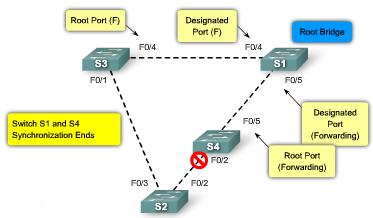
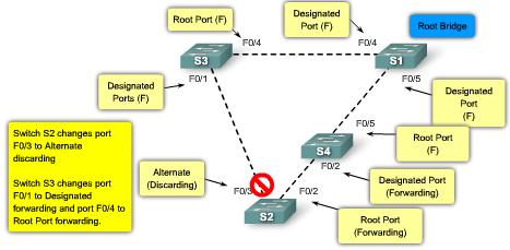
21 RSTP Proposal or Agreement Process a link between the root bridge and Bridge A is added. Convergence with 802.1D In IEEE 802.1D STP, when a port has been selected by spanning tree to become a designated port, it must wait two times the forward delay before transitioning the port to the forwarding state. RSTP significantly speeds up the recalculation process after a topology change, because it converges on a link-by-link basis and does not rely on timers expiring before ports can transition. Rapid transition to the forwarding state can only be achieved on edge ports and point-to-point links. In RSTP, this condition corresponds to a designated port in the discarding state. the final network topology is reached, just in the time necessary for the new BPDUs to travel down the tree. No timer is involved in this quick convergence Convergence with 802.1w 21


22 1 RSTP Proposal or Agreement Process


23 RSTP Proposal or Agreement Process


24 More Complicate RSTP Proposal and Agreement Process Suppose a new link is created between the root and Switch A. Because Switch A receives superior information, it immediately knows that p1 is the new root port. Switch A then starts a sync to verify that all of its ports are insync with this new information. A port is in sync if it is in blocking state or edge port. p2 and p4 already meet one of the criteria. In order to be in sync Switch A just needs to block port p3, and assign it the discarding state. Now that all of its ports are in sync, Switch A can unblock its newly selected root port p1 and send an agreement message to reply to the root. Once p0 receives that agreement, it can immediately transition to the forwarding state. This is step 4 of the preceding figure. Notice that port p3 is left in a designated discarding state after the sync. In step 4, that port is in the exact same situation as port p0 is in step 1. It then starts to propose to its neighbor, and attempts to quickly transition to the forwarding state The proposal agreement mechanism is very fast, as it does not rely on any timers. If a designated discarding port does not receive an agreement after it sends a proposal, it slowly transitions to the forwarding state, and falls back to the traditional 802.1D com/warp/public/ 473/146.html 24


25 Configuring Rapid PVST+ Rapid PVST+ is a Cisco implementation of RSTP. It supports spanning tree for each VLAN It is the rapid STP variant to use in Cisco-based networks. Rapid PVST+ commands control the configuration of VLAN spanning-tree instances. A spanning-tree instance is created when an interface is assigned to a VLAN and is removed when the last interface is moved to another VLAN. As well, you can configure STP switch and port parameters before a spanning-tree instance is created. The Cisco 2960 switch supports PVST+, rapid PVST+, and MSTP, but only one version can be active for all VLANs at any time. s/switches/lan/catalyst2950/soft ware/release/12.1_14_ea1/confi guration/guide/swstp.html 25


26 Configuring Rapid PVST+ The example configuration shows the rapid PVST+ commands being enabled on switch S1. The show spanning-tree vlan vlan-id command shows the configuration of VLAN 10 on switch S1. Notice that the BID priority is set to The BID was set using the spanning-tree vlan vlan-id priority priority-number command. In this example, the show running-configuration command has been used to verify the rapid PVST+ configuration on S1. 26

27 Design STP for Trouble Avoidance Know Where the Root Is You now know that the primary function of the STA is to break loops that redundant links create in bridge networks. Do not leave it up to the STP to decide which bridge is root. For each VLAN, you can usually identify which switch can serve as root. Generally, choose a powerful bridge in the middle of the network. If you put the root bridge in the center of the network with a direct connection to the servers and routers, you reduce the average distance from the clients to the servers and routers. If switch S2 is the root, the link from S1 to S3 is blocked on S1 or S3. In this case, hosts that connect to switch S2 can access the server and the router in two hops. Hosts that connect to bridge S3 can access the server and the router in three hops. The average distance is two and one-half hops. If switch S1 is the root, the router and the server are reachable in two hops for both hosts that connect on S2 and S3. The average distance is now two hops. Note: For each VLAN, configure the root bridge and the backup root bridge using lower priorities. 27


28 Design STP for Trouble Avoidance In non-hierarchical networks you might need to tune the STP cost parameter to decide which ports to block. However, this tuning is usually not necessary if you have a hierarchical design and a root bridge in a good location. Knowing the location of redundant links helps you identify an accidental bridging loop and the cause. Also, knowing the location of blocked ports allows you to determine the location of the error. Minimize the Number of Blocked Ports The only critical action that STP takes is the blocking of ports. A good way to limit the risk inherent in the use of STP is to reduce the number of blocked ports as much as possible. VTP Pruning You do not need more than two redundant links between two nodes in a switched network. Distribution switches are dual-attached to two core switches, switches, C1 and C2. Users on switches S1 and S2 that connect on distribution switches are only in a subset of the VLANs available in the network. In the figure, there are three redundant paths between core switch C1 and core switch C2. This redundancy results in more blocked ports and a higher likelihood of a loop. Manual Pruning VTP pruning can help, but this feature is not necessary in the core of the network. In this figure, only an access VLAN is used to connect the distribution switches to the core. In this design, only one port is blocked per VLAN. Also, with this design, you can remove all redundant links in just one step if you shut down C1 or C2. 28

29 Design STP for Trouble Avoidance Use Layer 3 Switching Layer 3 switching means routing approximately at the speed of switching. A router performs two main functions: It builds a forwarding table. The router generally exchanges information with peers by way of routing protocols. It receives packets and forwards them to the correct interface based on the destination address. There is no speed penalty with the routing hop and an additional segment between C1 and C2. Leaving the VLAN by Layer 3 switching is as fast as bridging inside the VLAN. Core switch C1 and core switch C2 are Layer 3 switches. VLAN 20 and VLAN 30 are no longer bridged between C1 and C2, there is no possibility for a loop. STP no longer blocks any single port, so there is no potential for a bridging loop. 29
30 Design STP for Trouble Avoidance Keep STP Even If It Is Unnecessary Generally, disabling STP in a switched network is not worth the risk. Assuming you have removed all the blocked ports from the network and do not have any physical redundancy, it is strongly suggested that you do not disable STP. However, if a technician makes a connection error on a patch panel and accidentally creates a loop, the network will be negatively impacted. Keep Traffic off the Administrative VLAN and Do Not Have a Single VLAN Span the Entire Network In administrative VLAN, the switch behaves like a IP host. A high rate of broadcast traffic on the administrative VLAN can adversely ability to process vital BPDUs. Therefore, keep user traffic off the administrative VLAN. Until recently, there was no way to remove VLAN 1 from a trunk in a Cisco implementation. As of Cisco IOS Software Release 12.1(11b)E, you can remove VLAN 1 from trunks. VLAN 1 still exists, but it blocks traffic, which prevents any loop possibility. Though useful, this setup can be dangerous because a bridging loop on VLAN 1 affects all trunks, which can bring down the whole network. 30


31 Troubleshoot STP Operation: Switch or Link Failure In the animation you see that when a port fails in a network configured with STP, a broadcast storm may result. In the intial state of the STP failure scenario, switch S3 has a lower BID than S2 consequently the designated port between S3 and S2 is port S0/1 on switch S3. Switch S3 is considered to have a "better BPDU" than switch S
32 Troubleshoot STP Operation: Troubleshoot a Failure In-band access may not be available during a bridging loop. Therefore, out-of-band connectivity, such as console access may be required. For example, during a broadcast storm you may not be able to Telnet to the infrastructure devices. Before you troubleshoot a bridging loop, you need to know at least these items: Topology of the bridge network Location of the root bridge Location of the blocked ports and the redundant links This knowledge is essential. To know what to fix in the network, you need to know how the network looks when it works correctly. Most of the troubleshooting steps simply use show commands to try to identify error conditions. Knowledge of the network helps you focus on the critical ports on the key devices. 32
33 Troubleshoot STP Operation: PortFast Configuration Error You typically enable PortFast only for a port or interface that connects to a host. When the link comes up on this port, the bridge skips the first stages of the STA and directly transitions to the forwarding mode. Even with a PortFast configuration, the port or interface still participates in STP. Cisco IOS software have a feature called BPDU guard. BPDU guard disables a PortFast-configured port or interface if the port or interface receives a BPDU. 33

34 Troubleshoot STP Operation: PortFast Configuration Error Caution: Do not use PortFast on switch ports or interfaces that connect to other switches, hubs, or routers. Otherwise, you may create a network loop. If the looped traffic is very intensive, the switch can have trouble successfully transmitting the BPDU that stops the loop. This problem can delay the convergence considerably or in some extreme cases can actually bring down the network. In this example, port F0/1 on switch S1 is already forwarding. Port F0/2 has erroneously been configured with the PortFast feature. Therefore, when a second connection from switch S2 is connected to F0/2 on S1, the port automatically transitions to forwarding mode and creates a loop. 34
35 Troubleshoot STP Operation: Network Diameter Issues The default values for the STP timers impose a maximum network diameter of seven. The maximum network diameter restricts how far away swtiches in the network can be from each other. In this case, two distinct switches cannot be more than seven hops away. Part of this restriction comes from the age field that BPDUs carry. When a BPDU propagates from the root bridge toward the leaves of the tree, the age field increments each time the BPDU goes though a switch. If the root is too far away from some switches of the network, BPDUs will be dropped. Take special care if you plan to change STP timers from the default value. An STP timer change has an impact on the diameter of the network and the stability of the STP. What is the better way to take care of this magic number 7 issue? 35
36 ALL SYSTEMS DOWN Feb. 15, 2003 Issue of CIO Magazine Wednesday, 13 November, when a researcher at BIDMC an award winner for adoption of information technology (IT) launched a Napster-like utility for exchanging data with other researchers, flooding the center's computing network core with information. Suddenly, doctors could not call up patient medical records, lab reports took hours instead of minutes to come back, and automatic drug prescriptions didn t register. The act was "completely innocent," says John Halamka, chief information officer of CareGroup, a holding company for BIDMC and four other Boston-area hospitals. Here is why? An important feature of extensively switched networks is the spanning tree protocol (STP). Developed by Digital Equipment Corp. in the 1980s, STP finds the most efficient path for data to travel over the network. But, says Radia Perlman, the inventor of STP, now an engineer at Sun Microsystems Laboratories (Burlington, Mass.), the algorithm may become unstable if information has to pass through too many intermediary switches known as hops from any point on the network to any other point on the network. The IEEE specification for STP (802.1d) recommends a maximum of seven hops. If you are the CIO, how do you solve this? 36

37 Troubleshoot STP Operation: Network Diameter Issues Activities 37


38 Troubleshoot STP Operation: Network Diameter Issues Activities
39 STP Exercise Which ports will get blocked now? All links are 100 Mb links 16,000 AAAAAAAAAAAA 32,768 BBBBBBBBBBBB 32,768 CCCCCCCCCCC 32,768 DDDDDDDDDDDD 39 39
40 40
41 4, b.5423.c700 S3 S1:ROOT ROOT RP 0/2 0/1 0/2 0/3 DP DP DP 0/1 0/1 DP 32, b.53ef.d680 RP 0/2 0/3 0/2 RP DP S2 DP 0/1 S4 0/3 0/3 32, a8c , c.ce
42 STP Exercise Which ports will get blocked now? 32,768 AAAAAAAAAAAA 10 mb 32,768 BBBBBBBBBBBB 100 mb 10 mb 100 mb 100 mb 32,768 CCCCCCCCCCC 100 mb 32,768 DDDDDDDDDDDD 42


43 STP Exercise Which ports will get blocked now? ROOT ROOT Fa0/1 Fa0/2 Fa0/1 Fa0/2 Fa0/1 Fa0/2 Fa0/1 Fa0/2 None Root None Root 43
44 Summary Spanning Tree Protocol (STP) is used to prevent loops from being formed on redundant networks STP uses different port states & timers to logically prevent loops There is at least one switch in a network that serves as the root bridge Root bridge is elected using information found in BPDU frames Root ports are determined by the spanning tree algorithm and are closest to the root bridge 44
45 Summary STP lengthy convergence time (50 seconds) facilitated the development of: RSTP convergence time is Tony slightly Chen over COD 6 seconds Rapid PVST+ Cisco Networking Academy adds VLAN support to RSTP is the preferred spanning-tree protocol on a Cisco switch netowrk 45
Chapter 5. Spanning Tree Protocol (STP) Part II
 Part II") Chapter 5 Spanning Tree Protocol (STP) Part II CCNA3-1 Chapter 5-2 Note for Instructors These presentations are the result of a collaboration among the instructors at St. Clair College in Windsor, Ontario.
Chapter 5 Spanning Tree Protocol (STP) Part II CCNA3-1 Chapter 5-2 Note for Instructors These presentations are the result of a collaboration among the instructors at St. Clair College in Windsor, Ontario.
Chapter 5: STP. * What is STP? How does STP work?
 Chapter 5: STP * What is STP? How does STP work? * What would be the worst case scenario that could happen to a redundant path switched network with the STP is disabled? When multiple paths exist between
Configuring STP. Understanding Spanning-Tree Features CHAPTER
 CHAPTER 11 This chapter describes how to configure the Spanning Tree Protocol (STP) on your switch. For information about the Rapid Spanning Tree Protocol (RSTP) and the Multiple Spanning Tree Protocol
Implement Spanning Tree Protocols-PART-I. LAN Switching and Wireless Chapter 5 Modified by Tony Chen 05/01/2008
 Implement Spanning Tree Protocols-PART-I LAN Switching and Wireless Chapter 5 Modified by Tony Chen 05/01/2008 ITE I Chapter 6 2006 Cisco Systems, Inc. All rights reserved. Cisco Public 1 Notes: If you
The multiple spanning-tree (MST) implementation is based on the IEEE 802.1s standard.
 implementation is based on the IEEE 802.1s standard.") CHAPTER 18 This chapter describes how to configure the Cisco implementation of the IEEE 802.1s Multiple STP (MSTP) on the IE 3010 switch. Note The multiple spanning-tree (MST) implementation is based on
CHAPTER 18 This chapter describes how to configure the Cisco implementation of the IEEE 802.1s Multiple STP (MSTP) on the IE 3010 switch. Note The multiple spanning-tree (MST) implementation is based on
Understanding Rapid Spanning Tree Protocol (802.1w)
") Understanding Rapid Spanning Tree Protocol (802.1w) Contents Introduction Support of RSTP in Catalyst Switches New Port States and Port Roles Port States Port Roles New BPDU Format Full View of the Cisco
Understanding Rapid Spanning Tree Protocol (802.1w) Contents Introduction Support of RSTP in Catalyst Switches New Port States and Port Roles Port States Port Roles New BPDU Format Full View of the Cisco
Table of Contents. Cisco Understanding Rapid Spanning Tree Protocol (802.1w)
") Table of Contents Understanding Rapid Spanning Tree Protocol (802.1w)...1 Introduction...1 Support of RSTP in Catalyst Switches...2 New Port States and Port Roles...2 Port States...2 Port Roles...3 New
Table of Contents Understanding Rapid Spanning Tree Protocol (802.1w)...1 Introduction...1 Support of RSTP in Catalyst Switches...2 New Port States and Port Roles...2 Port States...2 Port Roles...3 New
Configuring Rapid PVST+
 This chapter contains the following sections: Information About Rapid PVST+, page 1, page 16 Verifying the Rapid PVST+ Configuration, page 24 Information About Rapid PVST+ The Rapid PVST+ protocol is the
Configuring Spanning Tree Protocol
 Finding Feature Information, page 1 Restrictions for STP, page 1 Information About Spanning Tree Protocol, page 2 How to Configure Spanning-Tree Features, page 14 Monitoring Spanning-Tree Status, page
Configuring Spanning Tree Protocol
 Restrictions for STP Restrictions for STP, on page 1 Information About Spanning Tree Protocol, on page 1 How to Configure Spanning-Tree Features, on page 13 Monitoring Spanning-Tree Status, on page 25
Implement Spanning Tree Protocols. LAN Switching and Wireless Chapter 5
 Implement Spanning Tree Protocols LAN Switching and Wireless Chapter 5 ITE I Chapter 6 2006 Cisco Systems, Inc. All rights reserved. Cisco Public 1 Objectives Explain the role of redundancy in a converged
Configuring Rapid PVST+ Using NX-OS
 Configuring Rapid PVST+ Using NX-OS This chapter describes how to configure the Rapid per VLAN Spanning Tree (Rapid PVST+) protocol on Cisco NX-OS devices. This chapter includes the following sections:
Configuring STP and RSTP
 7 CHAPTER Configuring STP and RSTP This chapter describes the IEEE 802.1D Spanning Tree Protocol (STP) and the ML-Series implementation of the IEEE 802.1W Rapid Spanning Tree Protocol (RSTP). It also explains
Configuring STP and Prestandard IEEE 802.1s MST
 20 CHAPTER This chapter describes how to configure the Spanning Tree Protocol (STP) and prestandard IEEE 802.1s Multiple Spanning Tree (MST) protocol on Catalyst 6500 series switches. Note The IEEE 802.1s
Configuring Rapid PVST+
 This chapter describes how to configure the Rapid per VLAN Spanning Tree (Rapid PVST+) protocol on Cisco NX-OS devices using Cisco Data Center Manager (DCNM) for LAN. For more information about the Cisco
Cisco Exam Interconnecting Cisco Networking Devices Part 2 Version: 10.0 [ Total Questions: 149 ]
![Cisco Exam Interconnecting Cisco Networking Devices Part 2 Version: 10.0 [ Total Questions: 149 ]](/thumbs/85/92420323.jpg "Cisco Exam Interconnecting Cisco Networking Devices Part 2 Version: 10.0 [ Total Questions: 149 ]") s@lm@n Cisco Exam 200-101 Interconnecting Cisco Networking Devices Part 2 Version: 10.0 [ Total Questions: 149 ] Topic break down Topic No. of Questions Topic 1: LAN Switching Technologies 18 Topic 2:
s@lm@n Cisco Exam 200-101 Interconnecting Cisco Networking Devices Part 2 Version: 10.0 [ Total Questions: 149 ] Topic break down Topic No. of Questions Topic 1: LAN Switching Technologies 18 Topic 2:
Spanning Tree Protocol(STP)
") Introduction Spanning Tree Protocol (STP) is a Layer 2 protocol that runs on bridges and switches. The specification for STP is IEEE 802.1D. The main purpose of STP is to ensure that you do not create
Introduction Spanning Tree Protocol (STP) is a Layer 2 protocol that runs on bridges and switches. The specification for STP is IEEE 802.1D. The main purpose of STP is to ensure that you do not create
Configuring Optional Spanning-Tree Features
 CHAPTER 20 This chapter describes how to configure optional spanning-tree features on the Catalyst 3750-E or 3560-E switch. You can configure all of these features when your switch is running the per-vlan
Copyright 2014 CertificationKits LLC. All Rights Reserved. 2
 Copyright 2014 CertificationKits LLC. All Rights Reserved. 2 Spanning Tree Protocol is a bridge protocol that enables a learning bridge to dynamically work around loops in a network topology by creating
Understanding and Configuring STP
 CHAPTER 14 This chapter describes how to configure the Spanning Tree Protocol (STP) on a Catalyst 4500 series switch. It also provides guidelines, procedures, and configuration examples. This chapter includes
Spanning-Tree Protocol
 Spanning-Tree Protocol Malin Bornhager Halmstad University Session Number 2002, Svenska-CNAP Halmstad University 1 Objectives Redundancy in a converged network Spanning-Tree Protocol (STP) STP Operation
Cisco Understanding Multiple Spanning Tree Protocol (802.1
 Cisco Understanding Multiple Spanning Tree Protocol (802.1 Table of Contents Understanding Multiple Spanning Tree Protocol (802.1s)...1 Introduction...1 Where to use MST...2 PVST+ Case...2 Standard 802.1q
Implementing Spanning Tree Protocol
 Transparent Bridging Implementing Spanning Tree Protocol A switch has the same characteristics as a transparent bridge., Cisco Systems, Inc. All rights reserved. 2-1, Cisco Systems, Inc. All rights reserved.
Objectives. 1. Introduction:
 University of Jordan Faculty of Engineering & Technology Computer Engineering Department Advance Networks Laboratory 0907529 Exp.5 Spanning-Tree Protocol (STP) Objectives 1. Explain the role of redundancy
Configuring Spanning Tree
 CHAPTER 8 Configuring Spanning Tree This chapter describes how to configure spanning tree on the Catalyst enterprise LAN switches. Note For information on configuring the PortFast, UplinkFast, and BackboneFast
Understanding Multiple Spanning Tree Protocol (802.1s)
") Understanding Multiple Spanning Tree Protocol (802.1s) Document ID: 24248 Introduction Where to Use MST PVST+ Case Standard 802.1q Case MST Case MST Region MST Configuration and MST Region Region Boundary
Understanding Multiple Spanning Tree Protocol (802.1s) Document ID: 24248 Introduction Where to Use MST PVST+ Case Standard 802.1q Case MST Case MST Region MST Configuration and MST Region Region Boundary
PASS4TEST. IT Certification Guaranteed, The Easy Way! We offer free update service for one year
 PASS4TEST IT Certification Guaranteed, The Easy Way! \ http://www.pass4test.com We offer free update service for one year Exam : 351-001 Title : CCIE Cisco Certified InterNetworking Expert Vendors : Cisco
STP Optional Characteristic Configuration
 Table of Contents Table of Contents Chapter 1 Configuring STP Optional Characteristic... 1 1.1 STP Optional Characteristic Introduction... 1 1.1.1 Port Fast... 1 1.1.2 BPDU Guard... 2 1.1.3 BPDU Filter...
Maintaining Specific VLAN Identification. Comparing ISL and 802.1Q. VLAN Trunking
 Maintaining Specific VLAN Identification Specifically developed for multi-vlan interswitch communications Places a unique identifier in each frame Functions at Layer 2 2003, Cisco Systems, Inc. All rights
Campus Networking Workshop. Layer 2 engineering Spanning Tree and VLANs
 Campus Networking Workshop Layer 2 engineering Spanning Tree and VLANs Switching Loop When there is more than one path between two switches What are the potential problems? Switching Loop If there is more
Spanning Tree Protocol
 For conceptual information about, see the Using the with the EtherSwitch Network Module section of the EtherSwitch Network feature module. Finding Feature Information, page 1 Information About, page 1
Table of Contents. (Rapid) Spanning Tree Protocol. A simple bridge loop. An even worse bridge loop. Bridge loops Two bridges Three bridges (R)STP
 Spanning Tree Protocol. A simple bridge loop. An even worse bridge loop. Bridge loops Two bridges Three bridges (R)STP") Table of Contents (Rapid) Spanning Tree Protocol (R)STP Karst Koymans Informatics Institute University of Amsterdam (version 18.4, 2018/11/16 13:23:04) Friday, November 16, 2018 Bridge loops Two bridges
Table of Contents (Rapid) Spanning Tree Protocol (R)STP Karst Koymans Informatics Institute University of Amsterdam (version 18.4, 2018/11/16 13:23:04) Friday, November 16, 2018 Bridge loops Two bridges
Cisco - Spanning Tree Protocol Problems and Related Design Considerations
 Page 1 of 19 Spanning Tree Protocol Problems and Related Design Considerations Document ID: 10556 This document contains Flash animation. Interactive: This document offers customized analysis of your Cisco
PrepKing. PrepKing
 PrepKing Number: 350-001 Passing Score: 800 Time Limit: 180 min File Version: 9.3 http://www.gratisexam.com/ PrepKing 350-001 Sections 1. Section 1.00 - Implement Layer 2 2. Section 2.00 - Implement IPv4
Implement VTP. LAN Switching and Wireless Chapter 4 Modified by Tony Chen 10/01/2008
 Implement VTP LAN Switching and Wireless Chapter 4 Modified by Tony Chen 10/01/2008 ITE I Chapter 6 2006 Cisco Systems, Inc. All rights reserved. Cisco Public 1 Notes: If you see any mistake on my PowerPoint
Spanning-Tree Protocol
 Spanning-Tree Protocol Agenda» What Problem is Solved by STP?» Understanding STP Root Bridge Election» BPDU Details and Pathcost» Understanding STP Root and Designated Port Election» Understanding and
Chapter 5. Spanning Tree Protocol (STP) Part I
 Part I") Chapter 5 Spanning Tree Protocol (STP) Part I CCNA3-1 Chapter 5-1 Note for Instructors These presentations are the result of a collaboration among the instructors at St. Clair College in Windsor, Ontario.
Chapter 5 Spanning Tree Protocol (STP) Part I CCNA3-1 Chapter 5-1 Note for Instructors These presentations are the result of a collaboration among the instructors at St. Clair College in Windsor, Ontario.
RSTP Configuration. Page 1 of 26
 RSTP Configuration Page 1 of 26 Content Chapter 1 STP Configuration... 1 1.1 STP Overview... 1 1.1.1 Function of STP...1 1.1.2 Protocol Packets of STP...1 1.1.3 Basic Concepts in STP... 1 1.1.4 Spanning-Tree
Configuring MSTP CHAPTER
 CHAPTER 16 Configuring MSTP This chapter describes how to configure the Cisco implementation of the IEEE 802.1s Multiple STP (MSTP) on the Catalyst 2960 switch. Note The multiple spanning-tree (MST) implementation
Token Ring VLANs and Related Protocols
 Token Ring VLANs and Related Protocols CHAPTER 4 Token Ring VLANs A VLAN is a logical group of LAN segments, independent of physical location, with a common set of requirements. For example, several end
Configuring MST Using Cisco NX-OS
 This chapter describes how to configure Multiple Spanning Tree (MST) on Cisco NX-OS devices. This chapter includes the following sections: Finding Feature Information, page 1 Information About MST, page
Introduction to OSPF
 Campus Networking Introduction to OSPF Workshop Campus Layer-2 Networking Network Workshop Design These materials are licensed under the Creative Commons Attribution-Noncommercial 3.0 Unported license
The following graphic shows a single switch VLAN configuration.
 7.1. VLAN A Virtual LAN (VLAN) can be defined as: Broadcast domains defined by switch port rather than network address. A grouping of devices based on service need, protocol, or other criteria rather than
CCNA 3 (v v6.0) Chapter 3 Exam Answers % Full
 Chapter 3 Exam Answers % Full") CCNA 3 (v5.0.3 + v6.0) Chapter 3 Exam Answers 2017 100% Full ccnav6.com /ccna-3-v5-0-3-v6-0-chapter-3-exam-answers-2017-100-full.html CCNA Exam Answers 2017 CCNA 3 (v5.0.3 + v6.0) Chapter 3 Exam Answers
CCNA 3 (v5.0.3 + v6.0) Chapter 3 Exam Answers 2017 100% Full ccnav6.com /ccna-3-v5-0-3-v6-0-chapter-3-exam-answers-2017-100-full.html CCNA Exam Answers 2017 CCNA 3 (v5.0.3 + v6.0) Chapter 3 Exam Answers
Describing the STP. 2003, Cisco Systems, Inc. All rights reserved. 2-1
 Describing the STP 2003, Cisco Systems, Inc. All rights reserved. 2-1 IEEE Documents IEEE 802.1D IEEE 802.1Q IEEE 802.1w IEEE 802.1s - Media Access Control (MAC) bridges - Virtual Bridged Local Area Networks
MSTP Configuration. Page 1 of 24
 MSTP Configuration Page 1 of 24 Contents Chapter1 Configuring MSTP... 3 1.1 Brief Introduction to MSTP...3 1.2 BPDU...3 1.2.1 Basic Concepts in MSTP... 4 1.2.2 Roles of Ports... 6 1.3 Algorithm Implementation...9
Table of Contents 1 MSTP Configuration 1-1
 Table of Contents 1 MSTP Configuration 1-1 Overview 1-1 Introduction to STP 1-1 Why STP 1-1 Protocol Packets of STP 1-1 Basic Concepts in STP 1-2 How STP works 1-3 Introduction to RSTP 1-9 Introduction
Buy full file at
 14 Chapter 2 LAN Redundancy Chapter 2 LAN Redundancy 2.0.1.2 Class Activity Stormy Traffic ( ) Objective Explain the purpose of the Spanning Tree Protocol (STP) in a switched LAN environment with redundant
MSTP Configuration. Configuration
 MSTP Configuration Contents 1. Configuring MSTP...2 1.1 Brief Introduction to MSTP... 2 1.2 BPDU... 2 1.2.1 Basic Concepts in MSTP...2 1.2.2 Roles of Ports...4 1.3 Algorithm Implementation... 7 1.3.1 MSTP
2.2 Cisco IOS Commands for the Catalyst 4500 Series Switches snmp ifindex clear. This command has no arguments or keywords.
 Chapter 2 2.2 snmp ifindex clear snmp ifindex clear To clear any previously configured snmp ifindex commands that were entered for a specific interface, use the snmp ifindex clear command. snmp ifindex
Configuring STP Extensions
 Configuring STP Extensions This chapter describes the configuration of extensions to the Spanning Tree Protocol (STP) on Cisco Nexus 5000 Series switches. It includes the following sections: About STP
Describing the STP. IEEE Documents. Download this file. Enhancements to STP. Download: PT-Topology-STP2.pkt STP
 IEEE Documents IEEE 802.1D IEEE 802.1Q IEEE 802.1w IEEE 802.1s - Media Access Control (MAC) bridges - Virtual Bridged Local Area Networks - Rapid Reconfiguration (Supp. to 802.1D) - Multiple Spanning Tree
Exam Questions
 Exam Questions 200-105 ICND2 Interconnecting Cisco Networking Devices Part 2 (ICND2 v3.0) https://www.2passeasy.com/dumps/200-105/ 1.At which layer of the OSI model is RSTP used to prevent loops? A. physical
Layer 2/3 Configuration Guide, Cisco IOS XE Release 3.6E (Catalyst 3850 Switches)
") Layer 2/3 Configuration Guide, Cisco IOS XE Release 3.6E (Catalyst 3850 Switches) First Published: June 27, 2014 Americas Headquarters Cisco Systems, Inc. 170 West Tasman Drive San Jose, CA 95134-1706
Layer 2/3 Configuration Guide, Cisco IOS XE Release 3.6E (Catalyst 3850 Switches) First Published: June 27, 2014 Americas Headquarters Cisco Systems, Inc. 170 West Tasman Drive San Jose, CA 95134-1706
Configuring Optional STP Features
 CHAPTER 29 This chapter describes how to configure optional STP features. For complete syntax and usage information for the commands used in this chapter, see the Cisco IOS Master List, at this URL: http://www.cisco.com/en/us/docs/ios/mcl/allreleasemcl/all_book.html
62HConfiguring port role restriction 131H37. 63HConfiguring TC-BPDU transmission restriction 132H38. 64HEnabling TC-BPDU guard 133H38
 Contents Configuring spanning tree protocols 3 STP 3 STP protocol packets 3 Basic concepts in STP 4 Calculation process of the STP algorithm 5 RSTP 9 MSTP 10 MSTP features 10 MSTP basic concepts 10 How
Layer 2 Engineering Spanning Tree
 Layer 2 Engineering Spanning Tree Campus Network Design & Operations Workshop These materials are licensed under the Creative Commons Attribution-NonCommercial 4.0 International license (http://creativecommons.org/licenses/by-nc/4.0/)
Token Ring VLANs and Related Protocols
 CHAPTER 4 Token Ring VLANs and Related Protocols A VLAN is a logical group of LAN segments, independent of physical location, with a common set of requirements. For example, several end stations might
Download: PT-Topology-STP2.pkt
 IEEE Documents Describing the STP IEEE 802.1D IEEE 802.1Q IEEE 802.1w IEEE 802.1s - Media Access Control (MAC) bridges - Virtual Bridged Local Area Networks - Rapid Reconfiguration (Supp. to 802.1D) -
RSTP Configuration. RSTP Configuration
 RSTP Configuration Contents 16. STP Configuration...1 1.1 STP Overview...1 1.1.1 Function of STP... 1 1.1.2 Protocol Packets of STP... 1 1.1.3 Basic Concepts in STP... 1 1.1.4 Spanning-Tree Interface States...
Question No : 1 Which three of these statements regarding 802.1Q trunking are correct? (Choose three.)
") Volume: 149 Questions Question No : 1 Which three of these statements regarding 802.1Q trunking are correct? (Choose three.) A. 802.1Q native VLAN frames are untagged by default. B. 802.1Q trunking ports
Volume: 149 Questions Question No : 1 Which three of these statements regarding 802.1Q trunking are correct? (Choose three.) A. 802.1Q native VLAN frames are untagged by default. B. 802.1Q trunking ports
Implement Inter-VLAN Routing. LAN Switching and Wireless Chapter 6 Modified by Tony Chen 11/01/2008
 Implement Inter-VLAN Routing LAN Switching and Wireless Chapter 6 Modified by Tony Chen 11/01/2008 ITE I Chapter 6 2006 Cisco Systems, Inc. All rights reserved. Cisco Public 1 Notes: If you see any mistake
STP (Spanning Tree Protocol) - Step by Step Configuration Tutorial
 - Step by Step Configuration Tutorial") STP (Spanning Tree Protocol) - Step by Step Configuration Tutorial Introduction: Spanning Tree Protocol (STP) is a Layer 2 protocol that runs on switches. It was first introduced as CST (Common Spanning
STP (Spanning Tree Protocol) - Step by Step Configuration Tutorial Introduction: Spanning Tree Protocol (STP) is a Layer 2 protocol that runs on switches. It was first introduced as CST (Common Spanning
Configuring STP Extensions
 This chapter contains the following sections: Overview, page 1 Overview Cisco has added extensions to Spanning Tree Protocol (STP) that make convergence more efficient. In some cases, even though similar
material. For more information on how to get additional questions, please see
 Review Questions The following questions are designed to test your understanding of this chapter s material. For more information on how to get additional questions, please see www.lammle.com/ccn a. You
Troubleshooting Transparent Bridging Environments
 CHAPTER Troubleshooting Transparent Bridging Environments Transparent bridges were first developed at Digital Equipment Corporation (Digital) in the early 1980s and are now very popular in Ethernet/IEEE
Table of Contents. (Rapid) Spanning Tree Protocol. An even worse bridge loop. A simple bridge loop. Bridge loops Two bridges Three bridges (R)STP
 Spanning Tree Protocol. An even worse bridge loop. A simple bridge loop. Bridge loops Two bridges Three bridges (R)STP") Table of Contents (Rapid) Spanning Tree Protocol (R)STP Karst Koymans Informatics Institute University of Amsterdam (version 44, 2015/02/18 12:55:30) Thursday, February 19, 2015 Bridge loops Two bridges
Table of Contents (Rapid) Spanning Tree Protocol (R)STP Karst Koymans Informatics Institute University of Amsterdam (version 44, 2015/02/18 12:55:30) Thursday, February 19, 2015 Bridge loops Two bridges
DECUS IT-Symposium Spanning Tree Protocol Interoperability Cisco/HP ProCurve
 DECUS IT-Symposium 2006 Spanning Tree Protocol Interoperability Cisco/HP ProCurve Juergen Bruns Network Competency Center EMEA HP Services 2003 Hewlett-Packard Development Company, L.P. The information
Improving network convergence with Multiple Spanning Tree Protocol
 CEAI, Vol.15, No.1 pp. 79-87, 2013 Printed in Romania Improving network convergence with Multiple Spanning Tree Protocol Roxana Stănică SC Civitas Systems S.R.L., Craiova, Romania (e-mail: roxana_batm@yahoo.com)
Table of Contents Chapter 1 MSTP Configuration
 Table of Contents Table of Contents... 1-1 1.1 MSTP Overview... 1-1 1.1.1 MSTP Protocol Data Unit... 1-1 1.1.2 Basic MSTP Terminologies... 1-2 1.1.3 Implementation of MSTP... 1-6 1.1.4 MSTP Implementation
Managing Network Spanning Trees
 CHAPTER 8 This chapter describes, the IEEE 802.1d Spanning Tree Protocol (STP), and how to use and configure Cisco s proprietary spanning-tree protocols, Per VLAN Spanning Tree (PVST), Multiple Spanning
EIGRP Features and Operation
 EIGRP Features and Operation Enhanced IGRP (EIGRP) is a classless, enhanced distance-vector protocol. EIGRP is a Cisco proprietary protocol. EIGRP includes the subnet mask in its route updates. And as
MSTP Compatibility. Introduction. Topology. Autunm 2014
 MSTP Compatibility Autunm 2014 Topology Introduction As long as networks has been handled by hubs and switches according to the 802.1D standardization a magical protocol called Spanning-tree has been in
isco Understanding Spanning Tree Protocol Topology Chan
 isco Understanding Spanning Tree Protocol Topology Chan Table of Contents Understanding Spanning Tree Protocol Topology Changes...1 Interactive: This document offers customized analysis of your Cisco device...1
Question No: 1 On the MSTP network as shown in the figure, what is the role of the switch in MSTI 1 according to the configuration?
 Volume: 629 Questions Question No: 1 On the MSTP network as shown in the figure, what is the role of the switch in MSTI 1 according to the configuration? A. Root switch B. Slave switch C. Non-root switch
3. INTERCONNECTING NETWORKS WITH SWITCHES. THE SPANNING TREE PROTOCOL (STP)
") 3. INTERCONNECTING NETWORKS WITH SWITCHES. THE SPANNING TREE PROTOCOL (STP) 3.1. STP Operation In an extended Ethernet network (a large network, including many switches) multipath propagation may exist
3. INTERCONNECTING NETWORKS WITH SWITCHES. THE SPANNING TREE PROTOCOL (STP) 3.1. STP Operation In an extended Ethernet network (a large network, including many switches) multipath propagation may exist
Table of Contents. (Rapid) Spanning Tree Protocol. A simple bridge loop. An even worse bridge loop. Bridge loops Two bridges Three bridges (R)STP
 Spanning Tree Protocol. A simple bridge loop. An even worse bridge loop. Bridge loops Two bridges Three bridges (R)STP") Table of Contents (Rapid) Spanning Tree Protocol (R)STP Karst Koymans Informatics Institute University of Amsterdam (version 34, 2014/02/17 14:41:48) Monday, February 17, 2014 Bridge loops Two bridges
Table of Contents (Rapid) Spanning Tree Protocol (R)STP Karst Koymans Informatics Institute University of Amsterdam (version 34, 2014/02/17 14:41:48) Monday, February 17, 2014 Bridge loops Two bridges
Spanning Tree Protocol, from a feature CCNA s Perspective.
 Spanning Tree Protocol, from a feature CCNA s Perspective. written by Gerald C. Paciello Jan. 29, 2015 A little bit of history. Before we talk about Spanning Tree Protocol, let's organize the different
Configuring Spanning Tree Protocol
 CHAPTER 7 This chapter descibes how to configure Spanning Tree Protocol (STP) on the Cisco wireless mobile interface card (WMIC). Note For complete syntax and usage information for the commands used in
Configuring Optional STP Features
 CHAPTER 16 This chapter describes how to configure optional STP features. Note For complete syntax and usage information for the commands used in this chapter, refer to the Catalyst 6500 Series Switch
802.1w Rapid Spanning Tree Protocol (RSTP) 802.1d Spanning Tree Protocol (STP)
 802.1d Spanning Tree Protocol (STP)") 13 802.1w Rapid Spanning Tree Protocol (RSTP) 802.1d Spanning Tree Protocol (STP) Contents Overview.................................................... 13-2 How Spanning Tree Operates.................................
13 802.1w Rapid Spanning Tree Protocol (RSTP) 802.1d Spanning Tree Protocol (STP) Contents Overview.................................................... 13-2 How Spanning Tree Operates.................................
Packet Switching on L2 (LAN Level)
") Packet Switching on L2 (LAN Level) Transparent Bridging (TB), Spanning Tree Protocol (STP), Rapid STP, L2 Bridging versus L3 Routing Agenda Introduction Transparent Bridging Basics Spanning Tree Protocol
Packet Switching on L2 (LAN Level) Transparent Bridging (TB), Spanning Tree Protocol (STP), Rapid STP, L2 Bridging versus L3 Routing Agenda Introduction Transparent Bridging Basics Spanning Tree Protocol
CCNA Semester 3 labs. Part 1 of 1 Labs for chapters 1 8
 CCNA Semester 3 labs Part 1 of 1 Labs for chapters 1 8 2.1.2.12 Lab - Building a Switched Network with Redundant Links 2.3.2.3 Lab - Configuring Rapid PVST+, PortFast and BPDU Guard 2.4.3.4 Lab - Configuring
2V] Chapter 2 Catalyst 3560 Switch Cisco IOS Commands shutdown. This command has no arguments or keywords.
![2V] Chapter 2 Catalyst 3560 Switch Cisco IOS Commands shutdown. This command has no arguments or keywords.](/thumbs/72/66270180.jpg "2V] Chapter 2 Catalyst 3560 Switch Cisco IOS Commands shutdown. This command has no arguments or keywords.") 2V] Chapter 2 Catalyst 3560 Switch Cisco IOS Commands shutdown shutdown Use the shutdown interface configuration command to disable an interface. Use the no form of this command to restart a disabled interface.
2V] Chapter 2 Catalyst 3560 Switch Cisco IOS Commands shutdown shutdown Use the shutdown interface configuration command to disable an interface. Use the no form of this command to restart a disabled interface.
The Spanning Tree 802.1D (2004) RSTP MSTP
 RSTP MSTP") The Spanning Tree 802.1D (2004) RSTP MSTP (C) Herbert Haas 2005/03/11 http://www.perihel.at 1 Problem Description We want redundant links in bridged networks But transparent bridging cannot deal with redundancy
The Spanning Tree 802.1D (2004) RSTP MSTP (C) Herbert Haas 2005/03/11 http://www.perihel.at 1 Problem Description We want redundant links in bridged networks But transparent bridging cannot deal with redundancy
MSTP Technology White Paper
 MSTP Technology White Paper Key words: STP, RSTP, MSTP, rapid transition, multiple instances, redundancy loop, redundancy link, load sharing Abstract: This article introduces basic MSTP terms, MSTP algorithm
: Building Cisco Multilayer Switched Networks
 Exam : Cisco 642-812 Title : Building Cisco Multilayer Switched Networks Version : Demo Cheat-Test,help you pass any IT exam! Q: 1 Which three statements about the Multiple Spanning Tree (MST) protocol
Bridging Transmitting Non-IP Traffic or Merging Two Networks
 10 Bridging Transmitting Non-IP Traffic or Merging Two Networks Contents Overview..................................................... 10-3 Transmitting Non-IP Traffic..................................
Question No: 1 What is the maximum number of switches that can be stacked using Cisco StackWise?
 Volume: 283 Questions Question No: 1 What is the maximum number of switches that can be stacked using Cisco StackWise? A. 4 B. 5 C. 8 D. 9 E. 10 F. 13 Answer: D Question No: 2 A network engineer wants
Spanning-Tree Protocol
 Spanning-Tree Protocol Spanning Tree Protocol (IEEE 802.1D 1998), Rapid STP (IEEE 802.1D 2004), Cisco PVST+, MSTP Page 07-1 Agenda Spanning Tree Protocol (STP) Introduction Details Convergence Some more
Document ID: Contents. Introduction. Prerequisites. Requirements. Components Used. Conventions. Background Information.
 Products & Services Spanning Tree from PVST+ to Rapid-PVST Migration Configuration Example Document ID: 72836 Contents Introduction Prerequisites Requirements Components Used Conventions Background Information
CHAPTER 1 Introduction to Scaling Networks
 CHAPTER 1 Introduction to Scaling Networks As a business grows, so does its networking requirements. To keep pace with a business s expansion and new emerging technologies, a network must be designed to
Agenda. Spanning-Tree Protocol. Spanning Tree Protocol (STP) Introduction Details Convergence Some more details
 Introduction Details Convergence Some more details") Agenda Spanning-Tree Protocol Spanning Tree Protocol (STP) Introduction Details Convergence Some more details Rapid Spanning Tree Protocol (RSTP) Cisco PVST, PVST+ Multiple Spanning Tree Protocol (MSTP)
Agenda Spanning-Tree Protocol Spanning Tree Protocol (STP) Introduction Details Convergence Some more details Rapid Spanning Tree Protocol (RSTP) Cisco PVST, PVST+ Multiple Spanning Tree Protocol (MSTP)
Troubleshooting Transparent Bridging Environments
 Troubleshooting Transparent Bridging Environments Document ID: 10543 This information from the Internetwork Troubleshooting Guide was first posted on CCO here. As a service to our customers, selected chapters
CIS 83 Lab Assignment
 CIS 83 Lab Assignment Open the Packet Tracer Scenario STP Configuration Lab-1.pkt. Before proceeding, save as STP Configuration Lab-1-working.pkt. To demonstrate completion of the lab you will be asked
Configuring VLANs. Understanding VLANs CHAPTER
 CHAPTER 12 This chapter describes how to configure normal-range VLANs (VLAN IDs 1 to 1005) and extended-range VLANs (VLAN IDs 1006 to 4094) on the switch. It includes information about VLAN membership
CS IT. Lecture (06) STP (I) Problem statement. By: Dr. Ahmed ElShafee
 STP (I) Problem statement. By: Dr. Ahmed ElShafee") Lecture (06) STP (I) By: Dr. Ahmed ElShafee CS IT Problem statement If your network consists of layer 2 switches that allow computers connect and exchange data, you will need to consider the design that
Lecture (06) STP (I) By: Dr. Ahmed ElShafee CS IT Problem statement If your network consists of layer 2 switches that allow computers connect and exchange data, you will need to consider the design that
CCNA Cisco Certified Network Associate CCNA (v3.0)
") 200-125 - CCNA Cisco Certified Network Associate CCNA (v3.0) 1.What is one benefit of PVST+? A. PVST+ supports Layer 3 load balancing without loops. B. PVST+ reduces the CPU cycles for all the switches
200-125 - CCNA Cisco Certified Network Associate CCNA (v3.0) 1.What is one benefit of PVST+? A. PVST+ supports Layer 3 load balancing without loops. B. PVST+ reduces the CPU cycles for all the switches
Configuring VLANs. Understanding VLANs CHAPTER
 CHAPTER 14 This chapter describes how to configure normal-range VLANs (VLAN IDs 1 to 1005) and extended-range VLANs (VLAN IDs 1006 to 4094) on the Catalyst 3750 switch. It includes information about VLAN
Implementing Multiple Spanning Tree Protocol
 Implementing Multiple Spanning Tree Protocol This module provides conceptual and configuration information for Multiple Spanning Tree Protocol on Cisco ASR 9000 Series Routers. Multiple Spanning Tree Protocol