CHAPTER 2: Computer Clusters for Scalable Parallel Computing. Presented by Faramarz Safi (Ph.D.) Islamic Azad University, Najafabad Branch
|
|
|
- Melinda Clarke
- 6 years ago
- Views:
Transcription
1 CHAPTER 2: Computer Clusters for Scalable Parallel Computing Presented by Faramarz Safi (Ph.D.) Islamic Azad University, Najafabad Branch 1
2 SUMMARY Clustering of computers enables scalable parallel and distributed computing in both science and business applications. This chapter is devoted to building cluster-structured massively parallel processors. We focus on the design principles and assessment of the hardware, software, middleware, and operating system support to achieve scalability, availability, programmability, single-system images, and fault tolerance in clusters. Only physical clusters are studied in this chapter. Virtual clusters will be studied in Chapters 3 and 4. 2
3 CLUSTERING FOR MASSIVE PARALLELISM A computer cluster is a collection of interconnected stand-alone computers which can work together collectively and cooperatively as a single integrated computing resource pool. Clustering explores massive parallelism at the job level and achieves high availability (HA) through stand-alone operations. The benefits of computer clusters and massively parallel processors (MPPs) include scalable performance, HA, fault tolerance, modular growth, and use of commodity components. These features can sustain the generation changes experienced in hardware, software, and network components. Cluster computing became popular in the mid-1990s as traditional mainframes and vector supercomputers were proven to be less cost-effective in many highperformance computing (HPC) applications. 3

4 Cluster Development Trends Milestone Cluster Systems Clustering has been a hot research challenge in computer architecture. Fast communication, job scheduling, SSI, and HA are active areas in cluster research. Table 2.1 lists some milestone cluster research projects and commercial cluster products. Details of these old clusters can be found in [14]. 4
5 2.1.2 Design Objectives of Computer Clusters Clusters have been classified in various ways in the literature. We classify clusters using six orthogonal attributes: scalability, packaging, control, homogeneity, programmability, and security. Scalability: Clustering of computers is based on the concept of modular growth. To scale a cluster from hundreds of uniprocessor nodes to a supercluster with 10,000 multicore nodes is a nontrivial task. The scalability could be limited by a number of factors, such as the multicore chip technology, cluster topology, packaging method, power consumption, and cooling scheme applied. The purpose is to achieve scalable performance constrained by the aforementioned factors. We have to also consider other limiting factors such as the memory wall, disk I/O bottlenecks, and latency tolerance, among others. 5
6 2.1.2 Design Objectives of Computer Clusters Packaging: Cluster nodes can be packaged in a compact or a slack fashion. In a compact cluster, the nodes are closely packaged in one or more racks sitting in a room, and the nodes are not attached to peripherals (monitors, keyboards, mice, etc.). In a slack cluster, the nodes are attached to their usual peripherals (i.e., they are complete SMPs, workstations, and PCs), and they may be located in different rooms, different buildings, or even remote regions. Packaging directly affects communication wire length, and thus the selection of interconnection technology used. While a compact cluster can utilize a high-bandwidth, low-latency communication network that is often proprietary, nodes of a slack cluster are normally connected through standard LANs or WANs. 6
7 2.1.2 Design Objectives of Computer Clusters Control: A cluster can be either controlled or managed in a centralized or decentralized fashion. A compact cluster normally has centralized control, while a slack cluster can be controlled either way. In a centralized cluster, all the nodes are owned, controlled, managed, and administered by a central operator. In a decentralized cluster, the nodes have individual owners. For instance, consider a cluster comprising an interconnected set of desktop workstations in a department, where each workstation is individually owned by an employee. The owner can reconfigure, upgrade, or even shut down the workstation at any time. This lack of a single point of control makes system administration of such a cluster very difficult. It also calls for special techniques for process scheduling, workload migration, check pointing, accounting, and other similar tasks. 7
8 2.1.2 Design Objectives of Computer Clusters Homogeneity: A homogeneous cluster uses nodes from the same platform, that is, the same processor architecture and the same operating system; often, the nodes are from the same vendors. A heterogeneous cluster uses nodes of different platforms. Interoperability is an important issue in heterogeneous clusters. For instance, process migration is often needed for load balancing or availability. In a homogeneous cluster, a binary process image can migrate to another node and continue execution. This is not feasible in a heterogeneous cluster, as the binary code will not be executable when the process migrates to a node of a different platform. 8
9 2.1.2 Design Objectives of Computer Clusters Security Intracluster communication can be either exposed or enclosed. In an exposed cluster, the communication paths among the nodes are exposed to the outside world. An outside machine can access the communication paths, and thus individual nodes, using standard protocols (e.g., TCP/IP). Such exposed clusters are easy to implement, but have several disadvantages: Being exposed, intracluster communication is not secure, unless the communication subsystem performs additional work to ensure privacy and security. Outside communications may disrupt intracluster communications in an unpredictable fashion. In an enclosed cluster, intracluster communication is shielded from the outside world, which alleviates the aforementioned problems. A disadvantage is that there is currently no standard for efficient, enclosed intracluster communication. 9
10 Dedicated versus Enterprise Clusters A dedicated cluster is typically installed in a deskside rack in a central computer room. It is homogeneously configured with the same type of computer nodes and managed by a single administrator group like a frontend host. Dedicated clusters are used as substitutes for traditional mainframes or supercomputers. A dedicated cluster is installed, used, and administered as a single machine. Many users can log in to the cluster to execute both interactive and batch jobs. The cluster offers much enhanced throughput, as well as reduced response time. An enterprise cluster is mainly used to utilize idle resources in the nodes. Each node is usually a full-fledged SMP, workstation, or PC, with all the necessary peripherals attached. The nodes are typically geographically distributed, and are not necessarily in the same room or even in the same building. The nodes are individually owned by multiple owners. The cluster administrator has only limited control over the nodes, as a node can be turned off at any time by its owner. The owner s local jobs have higher priority than enterprise jobs. The cluster is often configured with heterogeneous computer nodes. 10
11 2.1.3 Fundamental Cluster Design Issues Scalable Performance: This refers to the fact that scaling of resources (cluster nodes, memory capacity, I/O bandwidth, etc.) leads to a proportional increase in performance. Of course, both scale-up and scaledown capabilities are needed, depending on application demand or costeffectiveness considerations. Clustering is driven by scalability. Single-System Image (SSI): A set of workstations connected by an Ethernet network is not necessarily a cluster. A cluster is a single system. For example, suppose a workstation has a 300 Mflops/second processor, 512 MB of memory, and a 4 GB disk and can support 50 active users and 1,000 processes. By clustering 100 such workstations, can we get a single system that is equivalent to one huge workstation, or a mega-station, that has a 30 Gflops/second processor, 50 GB of memory, and a 400 GB disk and can support 5,000 active users and 100,000 processes? SSI techniques are aimed at achieving this goal. 11
12 2.1.3 Fundamental Cluster Design Issues Availability Support: Clusters can provide cost-effective HA capability with lots of redundancy in processors, memory, disks, I/O devices, networks, and operating system images. However, to realize this potential, availability techniques are required. Cluster Job Management: Clusters try to achieve high system utilization from traditional workstations or PC nodes that are normally not highly utilized. Job management software is required to provide batching, load balancing, parallel processing, and other functionality. Special software tools are needed to manage multiple jobs simultaneously. 12
13 2.1.3 Fundamental Cluster Design Issues Internode Communication: Because of their higher node complexity, cluster nodes cannot be packaged as compactly as MPP nodes. The internode physical wire lengths are longer in a cluster than in an MPP. This is true even for centralized clusters. A long wire implies greater interconnect network latency. But more importantly, longer wires have more problems in terms of reliability, clock skew, and cross talking. These problems call for reliable and secure communication protocols, which increase overhead. Clusters often use commodity networks (e.g., Ethernet) with standard protocols such as TCP/IP. Fault Tolerance and Recovery: Clusters of machines can be designed to eliminate all single points of failure. Through redundancy, a cluster can tolerate faulty conditions up to a certain extent. Heartbeat mechanisms can be installed to monitor the running condition of all nodes. In case of a node failure, critical jobs running on the failing nodes can be saved by failing over to the surviving node machines. Rollback recovery schemes restore the computing results through periodic checkpointing. 13
14 2.1.3 Fundamental Cluster Design Issues Cluster Family Classification: Compute clusters: These are clusters designed mainly for collective computation over a single large job. A good example is a cluster dedicated to numerical simulation of weather conditions. The compute clusters do not handle many I/O operations, such as database services. Beowulf cluster: When a single compute job requires frequent communication among the cluster nodes, the cluster must share a dedicated network, and thus the nodes are mostly homogeneous and tightly coupled. Computational Grid: When the nodes require internode communication over a small number of heavy-duty nodes, they are essentially known as a computational grid. Tightly coupled compute clusters are designed for supercomputing applications. Compute clusters apply middleware such as a message-passing interface (MPI) or Parallel Virtual Machine (PVM) to port programs to a wide variety of clusters. 14
15 2.1.3 Fundamental Cluster Design Issues Cluster Family Classification: High-Availability clusters HA (high-availability) clusters are designed to be fault-tolerant and achieve HA of services. HA clusters operate with many redundant nodes to sustain faults or failures. The simplest HA cluster has only two nodes that can fail over to each other. Of course, high redundancy provides higher availability. HA clusters should be designed to avoid all single points of failure. Load-balancing clusters: These clusters shoot for higher resource utilization through load balancing among all participating nodes in the cluster. Requests initiated from the user are distributed to all node computers to form a cluster. This results in a balanced workload among different machines, and thus higher resource utilization or higher performance. Middleware is needed to achieve dynamic load balancing by job or process migration among all the cluster nodes. 15
16 16
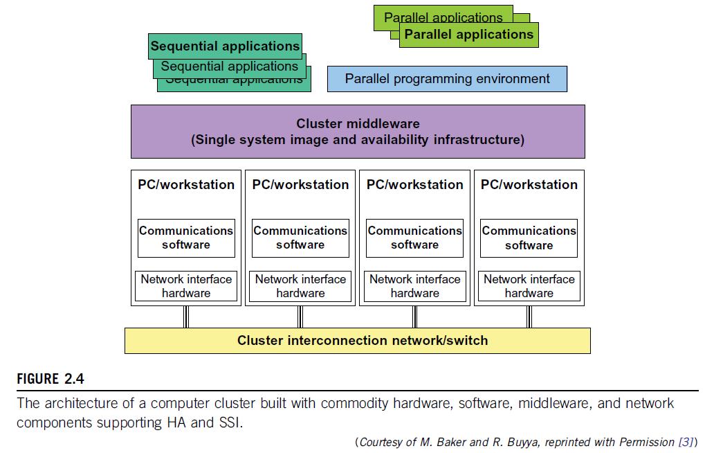
17 2.2.1 Cluster Organization and Resource Sharing A Basic Cluster Architecture Figure 2.4 shows the basic architecture of a computer cluster over PCs or workstations. The figure shows a simple cluster of computers built with commodity components and fully supported with desired SSI features and HA capability. The processing nodes are commodity workstations, PCs, or servers. These commodity nodes are easy to replace or upgrade with new generations of hardware. The node operating systems should be designed for multiuser, multitasking, and multithreaded applications. The nodes are interconnected by one or more fast commodity networks. These networks use standard communication protocols and operate at a speed that should be two orders of magnitude faster than that of the current TCP/IP speed over Ethernet. The network interface card is connected to the node s standard I/O bus (e.g., PCI). 17
18 A Basic Cluster Architecture When the processor or the operating system is changed, only the driver software needs to change. We desire to have a platform-independent cluster operating system, sitting on top of the node platforms. But such a cluster OS is not commercially available. Instead, we can deploy some cluster middleware to glue together all node platforms at the user space. An availability middleware offers HA services. An SSI layer provides a single entry point, a single file hierarchy, a single point of control, and a single job management system. Single memory may be realized with the help of the compiler or a runtime library. A single process space is not necessarily supported. 18
19 A Basic Cluster Architecture In general, an idealized cluster is supported by three subsystems: First, conventional databases and OLTP monitors offer users a desktop environment in which to use the cluster. In addition to running sequential user programs, the cluster supports parallel programming based on standard languages and communication libraries using PVM, MPI, or OpenMP. The programming environment also includes tools for debugging, profiling, monitoring, and so forth. A user interface subsystem is needed to combine the advantages of the web interface and the Windows GUI. It should also provide user-friendly links to various programming environments, job management tools, hypertext, and search support so that users can easily get help in programming the computer cluster. 19

20 Resource Sharing in Clusters There is no widely accepted standard for the memory bus. But there are such standards for the I/O buses. One recent, popular standard is the PCI I/O bus standard. So, if you implement an NIC card to attach a faster Ethernet network to the PCI bus you can be assured that this card can be used in other systems that use PCI as the I/O bus. 20
21 Resource Sharing in Clusters The nodes of a cluster can be connected in one of three ways, as shown in Figure 2.5: 1. The shared-nothing architecture is used in most clusters, where the nodes are connected through the I/O bus. The shared-nothing configuration in Part (a) simply connects two or more autonomous computers via a LAN such as Ethernet. 2. The shared-disk architecture is in favor of small-scale availability clusters in business applications. When one node fails, the other node takes over. A shareddisk cluster is shown in Part (b). This is what most business clusters desire so that they can enable recovery support in case of node failure. The shared disk can hold checkpoint files or critical system images to enhance cluster availability. Without shared disks, check-pointing, rollback recovery, failover, and failback are not possible in a cluster. 3. The shared-memory cluster in Part (c) is much more difficult to realize. The nodes could be connected by a scalable coherence interface (SCI) ring, which is connected to the memory bus of each node through an NIC module. In the other two architectures, the interconnect is attached to the I/O bus. The memory bus operates at a higher frequency than the I/O bus. 21
22 2.2.2 Node Architectures and MPP Packaging In building large-scale clusters or MPP systems, cluster nodes are classified into two categories: 1) compute nodes, and 2) service nodes. Compute nodes appear in larger quantities mainly used for largescale searching or parallel floating-point computations. Service nodes could be built with different processors mainly used to handle I/O, file access, and system monitoring. For MPP clusters, the compute nodes dominate in system cost, because we may have 1,000 times more compute nodes than service nodes in a single large clustered system. In the past, most MPPs are built with a homogeneous architecture by interconnecting a large number of the same compute nodes. In 2010, the Cray XT5 Jaguar system was built with 224,162 AMD Opteron processors with six cores each. The Tiahe-1A adopted a hybrid node design using two Xeon CPUs plus two AMD GPUs per each compute node. The GPU could be replaced by special floating-point accelerators. A homogeneous node design makes it easier to program and maintain the system. 22

23 2.2.2 Node Architectures and MPP Packaging Table 2.3 introduces two example compute node architectures: homogeneous design and hybrid node design. 23

24 Modular Packaging of the IBM Blue Gene/L System 24
25 Modular Packaging of the IBM Blue Gene/L System The Blue Gene/L is a supercomputer jointly developed by IBM and Lawrence Livermore National Laboratory. The system became operational in 2005 with a 136 Tflops performance at the No. 1 position in the Top-500 list toped the Japanese Earth Simulator. The system was upgraded to score a 478 Tflops speed in By examining the architecture of the Blue Gene series, we reveal the modular construction of a scalable MPP system as shown in Figure 2.6. With modular packaging, the Blue Gene/L system is constructed hierarchically from processor chips to 64 physical racks. This system was built with a total of 65,536 nodes with two PowerPC 449 FP2 processors per node. The 64 racks are interconnected by a huge 3D 64 x 32 x 32 torus network. 25
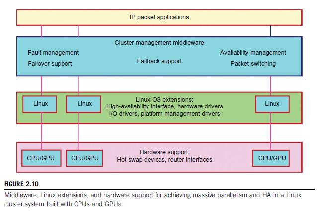
26 2.2.4 Hardware, Software, and Middleware Support Realistically, SSI and HA features in a cluster must be supported by hardware, software, middleware, or OS extensions. Any change in hardware design and OS extensions must be done by the manufacturer. The hardware and OS support could be cost-prohibitive to ordinary users. However, programming level is a big burden to cluster users. Therefore, the middleware support at the application level costs the least to implement. As an example, we show in Figure 2.10 the middleware, OS extensions, and hardware support needed to achieve HA in a typical Linux cluster system. Close to the user application end, middleware packages are also needed at the cluster management level: one for fault management to support failover and failback, to be discussed in Section Another desired feature is to achieve HA using failure detection and recovery and packet switching. In the middle of Figure 2.10, we need to modify the Linux OS to support HA, and we need special drivers to support HA, I/O, and hardware devices. Toward the bottom, we need special hardware to support hot-swapped devices and provide router interfaces. We will discuss various supporting mechanisms in subsequent sections. 26
27 27
28 2.2.5 GPU Clusters for Massive Parallelism Commodity GPUs are becoming high-performance accelerators for data-parallel computing. Modern GPU chips contain hundreds of processor cores per chip. Based on a 2010 report [19], each GPU chip is capable of achieving up to 1 Tflops for single-precision (SP) arithmetic, and more than 80 Gflops for double-precision (DP) calculations. Recent HPC-optimized GPUs contain up to 4 GB of on-board memory, and are capable of sustaining memory bandwidths exceeding 100 GB/second. GPU clusters are built with a large number of GPU chips. GPU clusters have already demonstrated their capability to achieve Pflops performance in some of the Top 500 systems. Most GPU clusters are structured with homogeneous GPUs of the same hardware class, make, and model. The software used in a GPU cluster includes the OS, GPU drivers, and clustering API such as an MPI. The high performance of a GPU cluster is attributed mainly to its massively parallel multicore architecture, high throughput in multithreaded floating-point arithmetic, and significantly reduced time in massive data movement using large on-chip cache memory. In other words, GPU clusters already are more cost-effective than traditional CPU clusters. GPU clusters result in not only a quantum jump in speed performance, but also significantly reduced space, power, and cooling demands. A GPU cluster can operate with a reduced number of operating system images, compared with CPU-based clusters. These reductions in power, environment, and management complexity make GPU clusters very attractive for use in future HPC applications. 28
29 CUDA Parallel Programming Interfaces CUDA (Compute Unified Device Architecture) offers a parallel computing architecture developed by NVIDIA. CUDA is the computing engine in NVIDIA GPUs. This software is accessible to developers through standard programming languages. Programmers use C for CUDA C with NVIDIA extensions and certain restrictions. This CUDA C is compiled through a Path Scale Open64 C compiler for parallel execution on a large number of GPU cores. Example 2.4 shows the advantage of using CUDA C in parallel processing. CUDA architecture shares a range of computational interfaces with two competitors: the Khronos Group s Open Computing Language and Microsoft s DirectCompute. Third-party wrappers are also available for using Python, Perl, FORTRAN, Java, Ruby, Lua, MATLAB, and IDL. CUDA has been used to accelerate non-graphical applications in computational biology, cryptography, and other fields by an order of magnitude or more. A good example is the BOINC distributed computing client. 29
30 Trends in CUDA Usage Tesla and Fermi are two generations of CUDA architecture released by NVIDIA in 2007 and 2010, respectively. The CUDA version 3.2 is used for using a single GPU module in A newer CUDA version 4.0 will allow multiple GPUs to address use an unified virtual address space of shared memory. The next NVIDIA GPUs will be Kepler-designed to support C++. The Fermi has eight times the peak double-precision floating-point performance of the Tesla GPU (5.8 Gflops/W versus 0.7 Gflops/W). Currently, the Fermi has up to 512 CUDA cores on 3 billion transistors. Future applications of the CUDA GPUs and the Echelon system may include the following: The search for extraterrestrial intelligence (SETI@Home) Distributed calculations to predict the native conformation of proteins Medical analysis simulations based on CT and MRI scan images Physical simulations in fluid dynamics and environment statistics Accelerated 3D graphics, cryptography, compression, and interconversion of video file formats Building the single-chip cloud computer (SCC) through virtualization in many-core architecture. 30
31 2.3 DESIGN PRINCIPLES OF COMPUTER CLUSTERS Clusters should be designed for scalability and availability. In this section, we will cover the design principles of SSI, HA, fault tolerance, and rollback recovery in general-purpose computers and clusters of cooperative computers. Single-System Image Features: 1) Single Entry Point 2) Single File Hierarchy 3) Visibility of Files 4) Support of Single-File Hierarchy 5) Single I/O, Networking, and Memory Space 6) Other Desired SSI Features 31
32 32
33 2.3 DESIGN PRINCIPLES OF COMPUTER CLUSTERS Single-System Image Features: SSI does not mean a single copy of an operating system image residing in memory, as in an SMP or a workstation. Rather, it means the illusion of a single system, single control, symmetry, and transparency as characterized in the following list: Single system: The entire cluster is viewed by users as one system that has multiple processors. The user could say, Execute my application using five processors. This is different from a distributed system. Single control: Logically, an end user or system user utilizes services from one place with a single interface. For instance, a user submits batch jobs to one set of queues; a system administrator configures all the hardware and software components of the cluster from one control point. Symmetry: A user can use a cluster service from any node. In other words, all cluster services and functionalities are symmetric to all nodes and all users, except those protected by access rights. Location-transparent: The user is not aware of the where is the physical device that eventually provides a service. For instance, the user can use a tape drive attached to any cluster node as though it were physically attached to the local node. 33
34 2.3 DESIGN PRINCIPLES OF COMPUTER CLUSTERS Single-System Image Features: The main motivation to have SSI is that it allows a cluster to be used, controlled, and maintained as a familiar workstation is. The word single in single-system image is sometimes synonymous with global or central. For instance, a global file system means a single file hierarchy, which a user can access from any node. A single point of control allows an operator to monitor and configure the cluster system. Although there is an illusion of a single system, a cluster service or functionality is often realized in a distributed manner through the cooperation of multiple components. From the viewpoint of a process P, cluster nodes can be classified into three types. The home node of a process P is the node where P resided when it was created. The local node of a process P is the node where P currently resides. All other nodes are remote nodes to P. 34
35 2.3 DESIGN PRINCIPLES OF COMPUTER CLUSTERS Single-System Image Features: A node can be configured to provide multiple functionalities. For instance, a node can be designated as a host, an I/O node, and a compute node at the same time. The illusion of an SSI can be obtained at several layers, three of which are discussed in the following list. Note that these layers may overlap with one another. Application software layer: Two examples are parallel web servers and various parallel databases. The user sees an SSI through the application and is not even aware that he is using a cluster. Hardware or kernel layer: Ideally, SSI should be provided by the operating system or by the hardware. Unfortunately, this is not a reality yet. Furthermore, it is extremely difficult to provide an SSI over heterogeneous clusters. With most hardware architectures and operating systems being proprietary, only the manufacturer can use this approach. Middleware layer: The most viable approach is to construct an SSI layer just above the OS kernel. This approach is promising because it is platform-independent and does not require application modification. 35
36 2.3 DESIGN PRINCIPLES OF COMPUTER CLUSTERS Single Entry Point Single-system image (SSI) is a very rich concept, consisting of single entry point, single file hierarchy, single I/O space, single networking scheme, single control point, single job management system, single memory space, and single process space. The single entry point enables users to log in (e.g., through Telnet, rlogin, or HTTP) to a cluster as one virtual host, although the cluster may have multiple physical host nodes to serve the login sessions. The system transparently distributes the user s login and connection requests to different physical hosts to balance the load. Clusters could substitute for mainframes and supercomputers. Also, in an Internet cluster server, thousands of HTTP or FTP requests may come simultaneously. Establishing a single entry point with multiple hosts is not a trivial matter. Many issues must be resolved. The following is just a partial list: Home directory Where do you put the user s home directory? Authentication How do you authenticate user logins? Multiple connections What if the same user opens several sessions to the same user account? Host failure How do you deal with the failure of one or more hosts? 36
37 2.3 DESIGN PRINCIPLES OF COMPUTER CLUSTERS Single Entry Point The DNS translates the symbolic name and returns the IP address of the least loaded node, which happens to be node Host1. The user then logs in using this IP address. The DNS periodically receives load information from the host nodes to make load-balancing translation decisions. In the ideal case, if 200 users simultaneously log in, the login sessions are evenly distributed among our hosts with 50 users each. This allows a single host to be four times more powerful. 37
38 2.3 DESIGN PRINCIPLES OF COMPUTER CLUSTERS Single File Hierarchy We use the term single file hierarchy to mean the illusion of a single, huge file system image that transparently integrates local and global disks and other file devices (e.g., tapes). All files a user needs are stored in some subdirectories of the root directory /, and they can be accessed through ordinary UNIX calls such as open, read, and so on. Multiple file systems can exist in a workstation as subdirectories of the root directory. The functionalities of a single file hierarchy have already been partially provided by existing distributed file systems such as Network File System (NFS) and Andrew File System (AFS). 38
39 2.3 DESIGN PRINCIPLES OF COMPUTER CLUSTERS Single File Hierarchy From the viewpoint of any process, files can reside on three types of locations in a cluster, as shown in Figure Local storage is the disk on the local node of a process. The disks on remote nodes are remote storage. A stable storage requires two aspects: 1) It is persistent, which means data, once written to the stable storage, will stay there for a sufficiently long time (e.g., a week), even after the cluster shuts down; and 2) it is fault-tolerant to some degree, by using redundancy and periodic backup to tapes. 39
40 2.3 DESIGN PRINCIPLES OF COMPUTER CLUSTERS Visibility of Files The term visibility here means a process can use traditional UNIX system or library calls such as fopen, fread, and fwrite to access files. Note that there are multiple local scratch directories in a cluster. The local scratch directories in remote nodes are not in the single file hierarchy, and are not directly visible to the process. The name scratch indicates that the storage is meant to act as a scratch pad for temporary information storage. Information in the local scratch space could be lost once the user logs out. Files in the global scratch space will normally persist even after the user logs out, but will be deleted by the system if not accessed in a predetermined time period. This is to free disk space for other users. The length of the period can be set by the system administrator, and usually ranges from one day to several weeks. Some systems back up the global scratch space to tapes periodically or before deleting any files. 40
41 2.3 DESIGN PRINCIPLES OF COMPUTER CLUSTERS Support of Single-File Hierarchy It is desired that a single file hierarchy have the SSI properties discussed, which are reiterated for file systems as follows: Single system: There is just one file hierarchy from the user s viewpoint. Symmetry: A user can access the global storage (e.g., /scratch) using a cluster service from any node. In other words, all file services and functionalities are symmetric to all nodes and all users, except those protected by access rights. Location-transparent: The user is not aware of the whereabouts of the physical device that eventually provides a service. For instance, the user can use a RAID attached to any cluster node as though it were physically attached to the local node. There may be some performance differences, though. A cluster file system should maintain UNIX semantics: Every file operation (fopen, fread, fwrite, fclose, etc.) is a transaction. When an fread accesses a file after an fwrite modifies the same file, the fread should get the updated value. to utilize the local disks in all nodes to form global storage. This solves the performance and availability problems of a single file server. 41
42 2.3 DESIGN PRINCIPLES OF COMPUTER CLUSTERS Single I/O, Networking, and Memory Space To achieve SSI, we desire a single control point, a single address space, a single job management system, a single user interface, and a single process control, as depicted in Figure In this example, each node has exactly one network connection. Two of the four nodes each have two I/O devices attached. Single Networking: A properly designed cluster should behave as one system (the shaded area). In other words, it is like a big workstation with four network connections and four I/O devices attached. Single I/O device: In other words, it is like a big workstation with four network connections and four I/O devices attached. Any process on any node can use any network and I/O device as though it were attached to the local node. 42
43 43
44 2.3 DESIGN PRINCIPLES OF COMPUTER CLUSTERS Single I/O, Networking, and Memory Space Single networking means any node can access any network connection. Single Point of Control: The system administrator should be able to configure, monitor, test, and control the entire cluster and each individual node from a single point. Many clusters help with this through a system console that is connected to all nodes of the cluster. The system console is normally connected to an external LAN (not shown in Figure 2.15) so that the administrator can log in remotely to the system console from anywhere in the LAN to perform administration work. Single Memory Space: Single memory space gives users the illusion of a big, centralized main memory, which in reality may be a set of distributed local memory spaces. PVPs, SMPs, and DSMs have an edge over MPPs and clusters in this respect, because they allow a program to utilize all global or local memory space. A good way to test if a cluster has a single memory space is to run a sequential program that needs a memory space larger than any single node can provide. 44
45 2.3 DESIGN PRINCIPLES OF COMPUTER CLUSTERS Single I/O, Networking, and Memory Space Single I/O Address Space: Assume the cluster is used as a web server. The web information database is distributed between the two RAIDs. An HTTP daemon is started on each node to handle web requests, which come from all four network connections. A single I/O space implies that any node can access the two RAIDs. Suppose most requests come from the ATM network. It would be beneficial if the functions of the HTTP on node 3 could be distributed to all four nodes. 45
46 2.3.2 High Availability through Redundancy When designing robust, highly available systems three terms are often used together: reliability, availability, and serviceability (RAS). Availability: Availability is the most interesting measure since it combines the concepts of reliability and serviceability. It indicates the percentage of time that a system is available to the user, that is, the percentage of system uptime. Reliability measures how long a system can operate without a breakdown. Serviceability refers to how easy it is to service the system, including hardware and software maintenance, repair, upgrades, and so on. The demand for RAS is driven by practical market needs. A recent Find/SVP survey found the following figures among Fortune 1000 companies: An average computer is down nine times per year with an average downtime of four hours. The average loss of revenue per hour of downtime is $82,500. With such a hefty penalty for downtime, many companies are striving for systems that offer 24/365 availability, meaning the system is available 24 hours per day, 365 days per year. 46
47 2.3.2 High Availability through Redundancy Availability and Failure Rate As Figure 2.18 shows, a computer system operates normally for a period of time before it fails. The failed system is then repaired, and the system returns to normal operation. This operate-repair cycle then repeats. A system s reliability is measured by the mean time to failure (MTTF), which is the average time of normal operation before the system (or a component of the system) fails. The metric for serviceability is the mean time to repair (MTTR), which is the average time it takes to repair the system and restore it to working condition after it fails. The availability of a system is defined by: Availability = MTTF/(MTTF+MTTR) 47
48 2.3.2 High Availability through Redundancy Planned versus Unplanned Failure When studying RAS, we call any event that prevents the system from normal operation a failure. This includes: Unplanned failures: The system breaks, due to an operating system crash, a hardware failure, a network disconnection, human operation errors, a power outage, and so on. All these are simply called failures. The system must be repaired to correct the failure. Planned shutdowns: The system is not broken, but is periodically taken off normal operation for upgrades, reconfiguration, and maintenance. A system may also be shut down for weekends or holidays. The MTTR in Figure 2.18 for this type of failure is the planned downtime. 48

49 2.3.2 High Availability through Redundancy Planned versus Unplanned Failure Table 2.5 shows the availability values of several representative systems. For instance, a conventional workstation has an availability of 99 percent, meaning it is up and running 99 percent of the time or it has a downtime of 3.6 days per year. An optimistic definition of availability does not consider planned downtime, which may be significant. For instance, many supercomputer installations have a planned downtime of several hours per week, while a telephone system cannot tolerate a downtime of a few minutes per year. 49
50 2.3.2 High Availability through Redundancy Transient versus Permanent Failures A lot of failures are transient in that they occur temporarily and then disappear. They can be dealt with without replacing any components. A standard approach is to roll back the system to a known state and start over. For instance, we all have rebooted our PC to take care of transient failures such as a frozen keyboard or window. Permanent failures cannot be corrected by rebooting. Some hardware or software component must be repaired or replaced. For instance, rebooting will not work if the system hard disk is broken. 50
51 2.3.2 High Availability through Redundancy Partial versus Total Failures A failure that renders the entire system unusable is called a total failure. A failure that only affects part of the system is called a partial failure if the system is still usable, even at a reduced capacity. A key approach to enhancing availability is to make as many failures as possible partial failures, by systematically removing single points of failure, which are hardware or software components whose failure will bring down the entire system. In an SMP (Figure 2.19(a)), the shared memory, the OS image, and the memory bus are all single points of failure. On the other hand, the processors are not forming a single point of failure. When a node fails in the clusters in Figure 2.19(b) and Figure 2.19(c), not only will the node applications all fail, but also all node data cannot be used until the node is repaired. The shared disk cluster in Figure 2.19(d) provides a remedy. The system stores persistent data on the shared disk, and periodically checkpoints to save intermediate results. When one WS node fails, the data will not be lost in this shared-disk cluster. 51
52 2.3.2 High Availability through Redundancy Partial versus Total Failures 52
53 2.3.2 High Availability through Redundancy Redundancy Techniques Consider the cluster in Figure 2.19(d). Assume only the nodes can fail. The rest of the system (e.g., interconnect and the shared RAID disk) is 100 percent available. Also assume that when a node fails, its workload is switched over to the other node in zero time. We ask, what is the availability of the cluster if planned downtime is ignored? What is the availability if the cluster needs one hour/week for maintenance? What is the availability if it is shut down one hour/week, one node at a time? According to Table 2.4, a workstation is available 99 percent of the time. The time both nodes are down is only 0.01 percent. Thus, the availability is percent. It is now a fault-resilient system, with only one hour of downtime per year. The planned downtime is 52 hours per year, that is, 52 / (365 24) = The total downtime is now 0.59 percent percent = 0.6 percent. The availability of the cluster becomes 99.4 percent. Suppose we ignore the unlikely situation in which the other node fails while one node is maintained. 53
54 2.3.2 High Availability through Redundancy Redundancy Techniques There are basically two ways to increase the availability of a system: increasing MTTF or reducing MTTR. Increasing MTTF amounts to increasing the reliability of the system. The computer industry has strived to make reliable systems, and today s workstations have MTTFs in the range of hundreds to thousands of hours. However, to further improve MTTF is very difficult and costly. Clusters offer an HA solution based on reducing the MTTR of the system. A multi-node cluster has a lower MTTF (thus lower reliability) than a workstation. However, the failures are taken care of quickly to deliver higher availability. We consider several redundancy techniques used in cluster design. 54
55 2.3.2 High Availability through Redundancy Isolated Redundancy A key technique to improve availability in any system is to use redundant components. When a component (the primary component) fails, the service it provided is taken over by another component (the backup component). Furthermore, the primary and the backup components should be isolated from each other, meaning they should not be subject to the same cause of failure. Clusters provide HA with redundancy in power supplies, fans, processors, memories, disks, I/O devices, networks, operating system images, and so on. 55
56 2.3.2 High Availability through Redundancy Isolated Redundancy In a carefully designed cluster, redundancy is also isolated. Isolated redundancy provides several benefits: First, a component designed with isolated redundancy is not a single point of failure, and the failure of that component will not cause a total system failure. Second, the failed component can be repaired while the rest of the system is still working. Third, the primary and the backup components can mutually test and debug each other. The IBM SP2 communication subsystem is a good example of isolatedredundancy design. All nodes are connected by two networks: an Ethernet network and a high-performance switch. Each node uses two separate interface cards to connect to these networks. There are two communication protocols: a standard IP and a user-space (US) protocol; each can run on either network. If either network or protocol fails, the other network or protocol can take over. 56
57 2.3.2 High Availability through Redundancy N-Version Programming to Enhance Software Reliability A common isolated-redundancy approach to constructing a missioncritical software system is called N-version programming. The software is implemented by N isolated teams who may not even know the others exist. Different teams are asked to implement the software using different algorithms, programming languages, environment tools, and even platforms. In a fault-tolerant system, the N versions all run simultaneously and their results are constantly compared. If the results differ, the system is notified that a fault has occurred. But because of isolated redundancy, it is extremely unlikely that the fault will cause a majority of the N versions to fail at the same time. So the system continues working, with the correct result generated by majority voting. In a highly available but less mission-critical system, only one version needs to run at a time. Each version has a built-in self-test capability. When one version fails, another version can take over. 57
58 2.3.3 Fault-Tolerant Cluster Configurations The cluster solution was targeted to provide availability support for two server nodes with three ascending levels of availability: hot standby active takeover fault-tolerant In this section, we will consider the recovery time, failback feature, and node activeness. The level of availability increases from standby to active and fault-tolerant cluster configurations. The shorter is the recovery time, the higher is the cluster availability. Failback refers to the ability of a recovered node returning to normal operation after repair or maintenance. Activeness refers to whether the node is used in active work during normal operation. 58
59 2.3.3 Fault-Tolerant Cluster Configurations Hot standby server clusters: In a hot standby cluster, only the primary node is actively doing all the useful work normally. The standby node is powered on (hot) and running some monitoring programs to communicate heartbeat signals to check the status of the primary node, but is not actively running other useful workloads. The primary node must mirror any data to shared disk storage, which is accessible by the standby node. The standby node requires a second copy of data. Active-takeover clusters: In this case, the architecture is symmetric among multiple server nodes. Both servers are primary, doing useful work normally. Both failover and failback are often supported on both server nodes. When a node fails, the user applications fail over to the available node in the cluster. Depending on the time required to implement the failover, users may experience some delays or may lose some data that was not saved in the last checkpoint. 59
60 2.3.3 Fault-Tolerant Cluster Configurations Failover cluster: This is probably the most important feature demanded in current clusters for commercial applications. When a component fails, this technique allows the remaining system to take over the services originally provided by the failed component. A failover mechanism must provide several functions, such as failure diagnosis, failure notification, and failure recovery. Failure diagnosis refers to the detection of a failure and the location of the failed component that caused the failure. A commonly used technique is heartbeat, whereby the cluster nodes send out a stream of heartbeat messages to one another. If the system does not receive the stream of heartbeat messages from a node, it can conclude that either the node or the network connection has failed. 60
61 2.3.3 Fault-Tolerant Cluster Configurations Recovery Schemes Failure recovery refers to the actions needed to take over the workload of a failed component. There are two types of recovery techniques. In backward recovery, the processes running on a cluster periodically save a consistent state (called a checkpoint) to a stable storage. After a failure, the system is reconfigured to isolate the failed component, restores the previous checkpoint, and resumes normal operation. This is called rollback. Backward recovery is relatively easy to implement in an application-independent, portable fashion, and has been widely used. However, rollback implies wasted execution. If execution time is crucial, such as in real-time systems where the rollback time cannot be tolerated, a forward recovery scheme should be used. With such a scheme, the system is not rolled back to the previous checkpoint upon a failure. Instead, the system utilizes the failure diagnosis information to reconstruct a valid system state and continues execution. Forward recovery is application-dependent and may need extra hardware. 61
62 2.3.4 Check-pointing and Recovery Techniques Checkpointing and recovery are two techniques that must be developed hand in hand, to enhance the availability of a cluster system. We will start with the basic concept of checkpointing. This is the process of periodically saving the state of an executing program to stable storage, from which the system can recover after a failure. Each program state saved is called a checkpoint. The disk file that contains the saved state is called the checkpoint file. Although all current checkpointing software saves program states in a disk, research is underway to use node memories in place of stable storage in order to improve performance. 62
63 2.3.4 Check-pointing and Recovery Techniques Kernel, Library, and Application Levels Checkpointing can be realized by the operating system at the kernel level, where the OS transparently checkpoints and restarts processes. This is ideal for users. However, checkpointing is not supported in most operating systems, especially for parallel programs. A less transparent approach links the user code with a checkpointing library in the user space. Checkpointing and restarting are handled by this runtime support. This approach is used widely because it has the advantage that user applications do not have to be modified. A main problem is that most current checkpointing libraries are static, meaning the application source code (or at least the object code) must be available. It does not work if the application is in the form of executable code. A third approach requires the user (or the compiler) to insert checkpointing functions in the application; thus, the application has to be modified, and the transparency is lost. However, it has the advantage that the user can specify where to checkpoint. This is helpful to reduce checkpointing overhead. Checkpointing incurs both time and storage overheads. 63
64 2.3.4 Check-pointing and Recovery Techniques Checkpoint Overheads and Choosing an Optimal Checkpoint Interval Checkpoint Overheads During a program s execution, its states may be saved many times. This is denoted by the time consumed to save one checkpoint. The storage overhead is the extra memory and disk space required for checkpointing. Both time and storage overheads depend on the size of the checkpoint file Choosing an Optimal Checkpoint Interval The time period between two checkpoints is called the checkpoint interval. Making the interval larger can reduce checkpoint time overhead. However, this implies a longer computation time after a failure. 64
65 2.3.4 Check-pointing and Recovery Techniques Choosing an Optimal Checkpoint Interval Wong and Franklin [28] derived an expression for optimal checkpoint interval as illustrated in Figure Optimal checkpoint interval = Square root (MTTF * t c )/h Here, MTTF is the system s mean time to failure. This MTTF accounts the time consumed to save one checkpoint, and h is the average percentage of normal computation performed in a checkpoint interval before the system fails. After a system is restored, it needs to spend h * (checkpoint interval) time to re-compute. 65
66 2.3.4 Check-pointing and Recovery Techniques Incremental Checkpoint: Instead of saving the full state at each checkpoint, an incremental checkpoint scheme saves only the portion of the state that is changed from the previous checkpoint. However, care must be taken regarding old checkpoint files. In full-state checkpointing, only one checkpoint file needs to be kept on disk. Subsequent checkpoints simply overwrite this file. 66
67 2.3.4 Check-pointing and Recovery Techniques Forked Checkpointing: Most checkpoint schemes are blocking in that the normal computation is stopped while checkpointing is in progress. With enough memory, checkpoint overhead can be reduced by making a copy of the program state in memory and invoking another asynchronous thread to perform the checkpointing concurrently. A simple way to overlap checkpointing with computation is to use the UNIX fork( ) system call. The forked child process duplicates the parent process s address space and checkpoints it. Meanwhile, the parent process continues execution. Overlapping is achieved since checkpointing is disk-i/o intensive. 67
68 2.3.4 Check-pointing and Recovery Techniques User-Directed Checkpointing: The checkpoint overheads can sometimes be substantially reduced if the user inserts code (e.g., library or system calls) to tell the system when to save, what to save, and what not to save. What should be the exact contents of a checkpoint? It should contain just enough information to allow a system to recover. The state of a process includes its data state and control state. For a UNIX process, these states are stored in its address space, including the text (code), the data, the stack segments, and the process descriptor. Saving and restoring the full state is expensive and sometimes impossible. For instance, the process ID and the parent process ID are not restorable, nor do they need to be saved in many applications. Most checkpointing systems save a partial state. For instance, the code segment is usually not saved, as it does not change in most applications. 68
69 2.3.4 Check-pointing and Recovery Techniques Checkpointing Parallel Programs We now turn to checkpointing parallel programs. The state of a parallel program is usually much larger than that of a sequential program, as it consists of the set of the states of individual processes, plus the state of the communication network. Parallelism also introduces various timing and consistency problems Consistent Snapshot A global snapshot is called consistent if there is no message that is received by the checkpoint of one process, but not yet sent by another process. Graphically, this corresponds to the case that no arrow crosses a snapshot line from right to left. Thus, snapshot a is consistent, because arrow x is from left to right. But snapshot c is inconsistent, as y goes from right to left. To be consistent, there should not be any zigzag path between two checkpoints [20]. For instance, checkpoints u and s cannot belong to a consistent global snapshot. A stronger consistency requires that no arrows cross the snapshot. Thus, only snapshot b is consistent in Figure
70 2.3.4 Check-pointing and Recovery Techniques Figure 2.21 illustrates checkpointing of a three-process parallel program. The arrows labeled x, y, and z represent point-to-point communication among the processes. The three thick lines labeled a, b, and c represent three global snapshots (or simply snapshots), where a global snapshot is a set of checkpoints (represented by dots), one from every process. In addition, some communication states may need to be saved. The intersection of a snapshot line with a process s time line indicates where the process should take a (local) checkpoint. Thus, the program s snapshot c consists of three local checkpoints: s, t, u for processes P, Q, and R, respectively, plus saving the communication y. 70
71 2.3.4 Check-pointing and Recovery Techniques Coordinated versus Independent Checkpointing Checkpointing schemes for parallel programs can be classified into two types. In coordinated checkpointing (also called consistent checkpointing), the parallel program is frozen, and all processes are checkpointed at the same time. In independent checkpointing, the processes are checkpointed independent of one another. These two types can be combined in various ways. Coordinated checkpointing is difficult to implement and tends to incur a large overhead. Independent checkpointing has a small overhead and can utilize existing checkpointing schemes for sequential programs. 71
72 2.4 CLUSTER JOB AND RESOURCE MANAGEMENT Cluster Job Scheduling Methods Cluster jobs may be scheduled to run at a specific time (calendar scheduling) or when a particular event happens (event scheduling). Table 2.6 summarizes various schemes to resolve job scheduling issues on a cluster. Jobs are scheduled according to priorities based on submission time, resource nodes, execution time, memory, disk, job type, and user identity. 72

73 2.4 CLUSTER JOB AND RESOURCE MANAGEMENT Cluster Job Scheduling Methods 73
Distributed and Cloud Computing
 Distributed and Cloud Computing K. Hwang, G. Fox and J. Dongarra Chapter 2: Computer Clusters for Scalable parallel Computing Adapted from Kai Hwang University of Southern California March 30, 2012 Copyright
Lecture 9: MIMD Architectures
 Lecture 9: MIMD Architectures Introduction and classification Symmetric multiprocessors NUMA architecture Clusters Zebo Peng, IDA, LiTH 1 Introduction MIMD: a set of general purpose processors is connected
Lecture 9: MIMD Architectures
 Lecture 9: MIMD Architectures Introduction and classification Symmetric multiprocessors NUMA architecture Clusters Zebo Peng, IDA, LiTH 1 Introduction A set of general purpose processors is connected together.
Lecture 9: MIMD Architecture
 Lecture 9: MIMD Architecture Introduction and classification Symmetric multiprocessors NUMA architecture Cluster machines Zebo Peng, IDA, LiTH 1 Introduction MIMD: a set of general purpose processors is
Chapter 18 Parallel Processing
 Chapter 18 Parallel Processing Multiple Processor Organization Single instruction, single data stream - SISD Single instruction, multiple data stream - SIMD Multiple instruction, single data stream - MISD
Distributed System Chapter 16 Issues in ch 17, ch 18
 Distributed System Chapter 16 Issues in ch 17, ch 18 1 Chapter 16: Distributed System Structures! Motivation! Types of Network-Based Operating Systems! Network Structure! Network Topology! Communication
CSCI 4717 Computer Architecture
 CSCI 4717/5717 Computer Architecture Topic: Symmetric Multiprocessors & Clusters Reading: Stallings, Sections 18.1 through 18.4 Classifications of Parallel Processing M. Flynn classified types of parallel
Module 16: Distributed System Structures. Operating System Concepts 8 th Edition,
 Module 16: Distributed System Structures, Silberschatz, Galvin and Gagne 2009 Chapter 16: Distributed System Structures Motivation Types of Network-Based Operating Systems Network Structure Network Topology
Module 16: Distributed System Structures
 Chapter 16: Distributed System Structures Module 16: Distributed System Structures Motivation Types of Network-Based Operating Systems Network Structure Network Topology Communication Structure Communication
Module 15: Network Structures
 Module 15: Network Structures Background Topology Network Types Communication Communication Protocol Robustness Design Strategies 15.1 A Distributed System 15.2 Motivation Resource sharing sharing and
Chapter 17: Distributed Systems (DS)
") Chapter 17: Distributed Systems (DS) Silberschatz, Galvin and Gagne 2013 Chapter 17: Distributed Systems Advantages of Distributed Systems Types of Network-Based Operating Systems Network Structure Communication
Chapter 17: Distributed Systems (DS) Silberschatz, Galvin and Gagne 2013 Chapter 17: Distributed Systems Advantages of Distributed Systems Types of Network-Based Operating Systems Network Structure Communication
The Use of Cloud Computing Resources in an HPC Environment
 The Use of Cloud Computing Resources in an HPC Environment Bill, Labate, UCLA Office of Information Technology Prakashan Korambath, UCLA Institute for Digital Research & Education Cloud computing becomes
Solace JMS Broker Delivers Highest Throughput for Persistent and Non-Persistent Delivery
 Solace JMS Broker Delivers Highest Throughput for Persistent and Non-Persistent Delivery Java Message Service (JMS) is a standardized messaging interface that has become a pervasive part of the IT landscape
Client Server & Distributed System. A Basic Introduction
 Client Server & Distributed System A Basic Introduction 1 Client Server Architecture A network architecture in which each computer or process on the network is either a client or a server. Source: http://webopedia.lycos.com
Outline. Definition of a Distributed System Goals of a Distributed System Types of Distributed Systems
 Distributed Systems Outline Definition of a Distributed System Goals of a Distributed System Types of Distributed Systems What Is A Distributed System? A collection of independent computers that appears
Chapter 18. Parallel Processing. Yonsei University
 Chapter 18 Parallel Processing Contents Multiple Processor Organizations Symmetric Multiprocessors Cache Coherence and the MESI Protocol Clusters Nonuniform Memory Access Vector Computation 18-2 Types
WHY PARALLEL PROCESSING? (CE-401)
") PARALLEL PROCESSING (CE-401) COURSE INFORMATION 2 + 1 credits (60 marks theory, 40 marks lab) Labs introduced for second time in PP history of SSUET Theory marks breakup: Midterm Exam: 15 marks Assignment:
PARALLEL PROCESSING (CE-401) COURSE INFORMATION 2 + 1 credits (60 marks theory, 40 marks lab) Labs introduced for second time in PP history of SSUET Theory marks breakup: Midterm Exam: 15 marks Assignment:
Operating Systems: Internals and Design Principles. Chapter 2 Operating System Overview Seventh Edition By William Stallings
 Operating Systems: Internals and Design Principles Chapter 2 Operating System Overview Seventh Edition By William Stallings Operating Systems: Internals and Design Principles Operating systems are those
Real Parallel Computers
 Real Parallel Computers Modular data centers Background Information Recent trends in the marketplace of high performance computing Strohmaier, Dongarra, Meuer, Simon Parallel Computing 2005 Short history
SWsoft ADVANCED VIRTUALIZATION AND WORKLOAD MANAGEMENT ON ITANIUM 2-BASED SERVERS
 SWsoft ADVANCED VIRTUALIZATION AND WORKLOAD MANAGEMENT ON ITANIUM 2-BASED SERVERS Abstract Virtualization and workload management are essential technologies for maximizing scalability, availability and
Distributed Systems. Lecture 4 Othon Michail COMP 212 1/27
 Distributed Systems COMP 212 Lecture 4 Othon Michail 1/27 What is a Distributed System? A distributed system is: A collection of independent computers that appears to its users as a single coherent system
Non-uniform memory access machine or (NUMA) is a system where the memory access time to any region of memory is not the same for all processors.
 is a system where the memory access time to any region of memory is not the same for all processors.") CS 320 Ch. 17 Parallel Processing Multiple Processor Organization The author makes the statement: "Processors execute programs by executing machine instructions in a sequence one at a time." He also says
CS 320 Ch. 17 Parallel Processing Multiple Processor Organization The author makes the statement: "Processors execute programs by executing machine instructions in a sequence one at a time." He also says
Cray XD1 Supercomputer Release 1.3 CRAY XD1 DATASHEET
 CRAY XD1 DATASHEET Cray XD1 Supercomputer Release 1.3 Purpose-built for HPC delivers exceptional application performance Affordable power designed for a broad range of HPC workloads and budgets Linux,
Computer-System Organization (cont.)
") Computer-System Organization (cont.) Interrupt time line for a single process doing output. Interrupts are an important part of a computer architecture. Each computer design has its own interrupt mechanism,
Computer-System Organization (cont.) Interrupt time line for a single process doing output. Interrupts are an important part of a computer architecture. Each computer design has its own interrupt mechanism,
Native vsphere Storage for Remote and Branch Offices
 SOLUTION OVERVIEW VMware vsan Remote Office Deployment Native vsphere Storage for Remote and Branch Offices VMware vsan is the industry-leading software powering Hyper-Converged Infrastructure (HCI) solutions.
ADAPTIVE AND DYNAMIC LOAD BALANCING METHODOLOGIES FOR DISTRIBUTED ENVIRONMENT
 ADAPTIVE AND DYNAMIC LOAD BALANCING METHODOLOGIES FOR DISTRIBUTED ENVIRONMENT PhD Summary DOCTORATE OF PHILOSOPHY IN COMPUTER SCIENCE & ENGINEERING By Sandip Kumar Goyal (09-PhD-052) Under the Supervision
BİL 542 Parallel Computing
 BİL 542 Parallel Computing 1 Chapter 1 Parallel Programming 2 Why Use Parallel Computing? Main Reasons: Save time and/or money: In theory, throwing more resources at a task will shorten its time to completion,
vsan Remote Office Deployment January 09, 2018
 January 09, 2018 1 1. vsan Remote Office Deployment 1.1.Solution Overview Table of Contents 2 1. vsan Remote Office Deployment 3 1.1 Solution Overview Native vsphere Storage for Remote and Branch Offices
Organisasi Sistem Komputer
 LOGO Organisasi Sistem Komputer OSK 14 Parallel Processing Pendidikan Teknik Elektronika FT UNY Multiple Processor Organization Single instruction, single data stream - SISD Single instruction, multiple
Chapter 18: Database System Architectures.! Centralized Systems! Client--Server Systems! Parallel Systems! Distributed Systems!
 Chapter 18: Database System Architectures! Centralized Systems! Client--Server Systems! Parallel Systems! Distributed Systems! Network Types 18.1 Centralized Systems! Run on a single computer system and
ACCRE High Performance Compute Cluster
 6 중 1 2010-05-16 오후 1:44 Enabling Researcher-Driven Innovation and Exploration Mission / Services Research Publications User Support Education / Outreach A - Z Index Our Mission History Governance Services
The MOSIX Scalable Cluster Computing for Linux. mosix.org
 The MOSIX Scalable Cluster Computing for Linux Prof. Amnon Barak Computer Science Hebrew University http://www. mosix.org 1 Presentation overview Part I : Why computing clusters (slide 3-7) Part II : What
High Availability and Disaster Recovery Solutions for Perforce
 High Availability and Disaster Recovery Solutions for Perforce This paper provides strategies for achieving high Perforce server availability and minimizing data loss in the event of a disaster. Perforce
Adapted from: TRENDS AND ATTRIBUTES OF HORIZONTAL AND VERTICAL COMPUTING ARCHITECTURES
 Adapted from: TRENDS AND ATTRIBUTES OF HORIZONTAL AND VERTICAL COMPUTING ARCHITECTURES Tom Atwood Business Development Manager Sun Microsystems, Inc. Takeaways Understand the technical differences between
Three Steps Toward Zero Downtime. Guide. Solution Guide Server.
 Three Steps Toward Zero Downtime Guide Solution Guide Server Server Solution Guide Three Steps Toward Zero Downtime Introduction Service uptime is a top priority for many business operations. From global
EMC Celerra CNS with CLARiiON Storage
 DATA SHEET EMC Celerra CNS with CLARiiON Storage Reach new heights of availability and scalability with EMC Celerra Clustered Network Server (CNS) and CLARiiON storage Consolidating and sharing information
The benefits of. Clustered storage offers advantages in both performance and scalability, but users need to evaluate three different architectures.
 The benefits of clustered block storage Clustered storage offers advantages in both performance and scalability, but users need to evaluate three different architectures. By Ray Lucchesi Today s data centers
Lecture 23 Database System Architectures
 CMSC 461, Database Management Systems Spring 2018 Lecture 23 Database System Architectures These slides are based on Database System Concepts 6 th edition book (whereas some quotes and figures are used
The Optimal CPU and Interconnect for an HPC Cluster
 5. LS-DYNA Anwenderforum, Ulm 2006 Cluster / High Performance Computing I The Optimal CPU and Interconnect for an HPC Cluster Andreas Koch Transtec AG, Tübingen, Deutschland F - I - 15 Cluster / High Performance
Cisco 4000 Series Integrated Services Routers: Architecture for Branch-Office Agility
 White Paper Cisco 4000 Series Integrated Services Routers: Architecture for Branch-Office Agility The Cisco 4000 Series Integrated Services Routers (ISRs) are designed for distributed organizations with
Chapter 20: Database System Architectures
 Chapter 20: Database System Architectures Chapter 20: Database System Architectures Centralized and Client-Server Systems Server System Architectures Parallel Systems Distributed Systems Network Types
Virtual Security Server
 Data Sheet VSS Virtual Security Server Security clients anytime, anywhere, any device CENTRALIZED CLIENT MANAGEMENT UP TO 50% LESS BANDWIDTH UP TO 80 VIDEO STREAMS MOBILE ACCESS INTEGRATED SECURITY SYSTEMS
Introduction to Parallel Processing
 Babylon University College of Information Technology Software Department Introduction to Parallel Processing By Single processor supercomputers have achieved great speeds and have been pushing hardware
Chapter 2 Parallel Hardware
 Chapter 2 Parallel Hardware Part I. Preliminaries Chapter 1. What Is Parallel Computing? Chapter 2. Parallel Hardware Chapter 3. Parallel Software Chapter 4. Parallel Applications Chapter 5. Supercomputers
High Performance Computing Course Notes Course Administration
 High Performance Computing Course Notes 2009-2010 2010 Course Administration Contacts details Dr. Ligang He Home page: http://www.dcs.warwick.ac.uk/~liganghe Email: liganghe@dcs.warwick.ac.uk Office hours:
EMC Integrated Infrastructure for VMware. Business Continuity
 EMC Integrated Infrastructure for VMware Business Continuity Enabled by EMC Celerra and VMware vcenter Site Recovery Manager Reference Architecture Copyright 2009 EMC Corporation. All rights reserved.
IBM. Systems management Disk management. IBM i 7.1
 IBM IBM i Systems management Disk management 7.1 IBM IBM i Systems management Disk management 7.1 Note Before using this information and the product it supports, read the information in Notices, on page
Parallel Processing. Computer Architecture. Computer Architecture. Outline. Multiple Processor Organization
 Computer Architecture Computer Architecture Prof. Dr. Nizamettin AYDIN naydin@yildiz.edu.tr nizamettinaydin@gmail.com Parallel Processing http://www.yildiz.edu.tr/~naydin 1 2 Outline Multiple Processor
Microsoft Office SharePoint Server 2007
 Microsoft Office SharePoint Server 2007 Enabled by EMC Celerra Unified Storage and Microsoft Hyper-V Reference Architecture Copyright 2010 EMC Corporation. All rights reserved. Published May, 2010 EMC
Tesla GPU Computing A Revolution in High Performance Computing
 Tesla GPU Computing A Revolution in High Performance Computing Mark Harris, NVIDIA Agenda Tesla GPU Computing CUDA Fermi What is GPU Computing? Introduction to Tesla CUDA Architecture Programming & Memory
Maximize the Speed and Scalability of Your MuleSoft ESB with Solace
 Maximize the Speed and Scalability of MuleSoft s Mule ESB enterprise service bus software makes information and interactive services accessible to a wide range of applications and users by intelligently
Introduction. Architecture Overview
 Performance and Sizing Guide Version 17 November 2017 Contents Introduction... 5 Architecture Overview... 5 Performance and Scalability Considerations... 6 Vertical Scaling... 7 JVM Heap Sizes... 7 Hardware
Veritas InfoScale Enterprise for Oracle Real Application Clusters (RAC)
") Veritas InfoScale Enterprise for Oracle Real Application Clusters (RAC) Manageability and availability for Oracle RAC databases Overview Veritas InfoScale Enterprise for Oracle Real Application Clusters
Veritas InfoScale Enterprise for Oracle Real Application Clusters (RAC) Manageability and availability for Oracle RAC databases Overview Veritas InfoScale Enterprise for Oracle Real Application Clusters
Microsoft SQL Server on Stratus ftserver Systems
 W H I T E P A P E R Microsoft SQL Server on Stratus ftserver Systems Security, scalability and reliability at its best Uptime that approaches six nines Significant cost savings for your business Only from
Lecture 1: January 22
 CMPSCI 677 Distributed and Operating Systems Spring 2018 Lecture 1: January 22 Lecturer: Prashant Shenoy Scribe: Bin Wang 1.1 Introduction to the course The lecture started by outlining the administrative
OL Connect Backup licenses
 OL Connect Backup licenses Contents 2 Introduction 3 What you need to know about application downtime 5 What are my options? 5 Reinstall, reactivate, and rebuild 5 Create a Virtual Machine 5 Run two servers
Best Practices for Setting BIOS Parameters for Performance
 White Paper Best Practices for Setting BIOS Parameters for Performance Cisco UCS E5-based M3 Servers May 2013 2014 Cisco and/or its affiliates. All rights reserved. This document is Cisco Public. Page
Dell Fluid Data solutions. Powerful self-optimized enterprise storage. Dell Compellent Storage Center: Designed for business results
 Dell Fluid Data solutions Powerful self-optimized enterprise storage Dell Compellent Storage Center: Designed for business results The Dell difference: Efficiency designed to drive down your total cost
06-Dec-17. Credits:4. Notes by Pritee Parwekar,ANITS 06-Dec-17 1
 Credits:4 1 Understand the Distributed Systems and the challenges involved in Design of the Distributed Systems. Understand how communication is created and synchronized in Distributed systems Design and
What are Clusters? Why Clusters? - a Short History
 What are Clusters? Our definition : A parallel machine built of commodity components and running commodity software Cluster consists of nodes with one or more processors (CPUs), memory that is shared by
Distributed OS and Algorithms
 Distributed OS and Algorithms Fundamental concepts OS definition in general: OS is a collection of software modules to an extended machine for the users viewpoint, and it is a resource manager from the
Trends in HPC (hardware complexity and software challenges)
") Trends in HPC (hardware complexity and software challenges) Mike Giles Oxford e-research Centre Mathematical Institute MIT seminar March 13th, 2013 Mike Giles (Oxford) HPC Trends March 13th, 2013 1 / 18
Trends in HPC (hardware complexity and software challenges) Mike Giles Oxford e-research Centre Mathematical Institute MIT seminar March 13th, 2013 Mike Giles (Oxford) HPC Trends March 13th, 2013 1 / 18
vsan Security Zone Deployment First Published On: Last Updated On:
 First Published On: 06-14-2017 Last Updated On: 11-20-2017 1 1. vsan Security Zone Deployment 1.1.Solution Overview Table of Contents 2 1. vsan Security Zone Deployment 3 1.1 Solution Overview VMware vsphere
Computer Organization. Chapter 16
 William Stallings Computer Organization and Architecture t Chapter 16 Parallel Processing Multiple Processor Organization Single instruction, single data stream - SISD Single instruction, multiple data
High Availability through Warm-Standby Support in Sybase Replication Server A Whitepaper from Sybase, Inc.
 High Availability through Warm-Standby Support in Sybase Replication Server A Whitepaper from Sybase, Inc. Table of Contents Section I: The Need for Warm Standby...2 The Business Problem...2 Section II:
TITLE: PRE-REQUISITE THEORY. 1. Introduction to Hadoop. 2. Cluster. Implement sort algorithm and run it using HADOOP
 TITLE: Implement sort algorithm and run it using HADOOP PRE-REQUISITE Preliminary knowledge of clusters and overview of Hadoop and its basic functionality. THEORY 1. Introduction to Hadoop The Apache Hadoop
VMware vsphere Clusters in Security Zones
 SOLUTION OVERVIEW VMware vsan VMware vsphere Clusters in Security Zones A security zone, also referred to as a DMZ," is a sub-network that is designed to provide tightly controlled connectivity to an organization
Unit 5: Distributed, Real-Time, and Multimedia Systems
 Unit 5: Distributed, Real-Time, and Multimedia Systems Unit Overview Unit 5 provides an extension to the core topics of operating systems. It introduces distributed systems and special-purpose operating
Highly Available Forms and Reports Applications with Oracle Fail Safe 3.0
 Highly Available Forms and Reports Applications with Oracle Fail Safe 3.0 High Availability for Windows NT An Oracle Technical White Paper Robert Cheng Oracle New England Development Center System Products
IBM i Version 7.3. Systems management Disk management IBM
 IBM i Version 7.3 Systems management Disk management IBM IBM i Version 7.3 Systems management Disk management IBM Note Before using this information and the product it supports, read the information in
Module 4 STORAGE NETWORK BACKUP & RECOVERY
 Module 4 STORAGE NETWORK BACKUP & RECOVERY BC Terminology, BC Planning Lifecycle General Conditions for Backup, Recovery Considerations Network Backup, Services Performance Bottlenecks of Network Backup,
OVERHEADS ENHANCEMENT IN MUTIPLE PROCESSING SYSTEMS BY ANURAG REDDY GANKAT KARTHIK REDDY AKKATI
 CMPE 655- MULTIPLE PROCESSOR SYSTEMS OVERHEADS ENHANCEMENT IN MUTIPLE PROCESSING SYSTEMS BY ANURAG REDDY GANKAT KARTHIK REDDY AKKATI What is MULTI PROCESSING?? Multiprocessing is the coordinated processing
Computer Organization and Structure. Bing-Yu Chen National Taiwan University
 Computer Organization and Structure Bing-Yu Chen National Taiwan University Storage and Other I/O Topics I/O Performance Measures Types and Characteristics of I/O Devices Buses Interfacing I/O Devices
BUSINESS CONTINUITY: THE PROFIT SCENARIO
 WHITE PAPER BUSINESS CONTINUITY: THE PROFIT SCENARIO THE BENEFITS OF A COMPREHENSIVE BUSINESS CONTINUITY STRATEGY FOR INCREASED OPPORTUNITY Organizational data is the DNA of a business it makes your operation
Workload Optimized Systems: The Wheel of Reincarnation. Michael Sporer, Netezza Appliance Hardware Architect 21 April 2013
 Workload Optimized Systems: The Wheel of Reincarnation Michael Sporer, Netezza Appliance Hardware Architect 21 April 2013 Outline Definition Technology Minicomputers Prime Workstations Apollo Graphics
High Throughput WAN Data Transfer with Hadoop-based Storage
 High Throughput WAN Data Transfer with Hadoop-based Storage A Amin 2, B Bockelman 4, J Letts 1, T Levshina 3, T Martin 1, H Pi 1, I Sfiligoi 1, M Thomas 2, F Wuerthwein 1 1 University of California, San
CENTRALIZED MANAGEMENT DELL POWERVAULT DL 2100 POWERED BY SYMANTEC
 CENTRALIZED MANAGEMENT DELL POWERVAULT DL 2100 POWERED BY SYMANTEC EXECUTIVE SUMMARY The PowerVault DL2100 Powered by Symantec Backup Exec offers the industry s only fully integrated backup-to-disk solution
Distributed Systems. Thoai Nam Faculty of Computer Science and Engineering HCMC University of Technology
 Distributed Systems Thoai Nam Faculty of Computer Science and Engineering HCMC University of Technology Chapter 1: Introduction Distributed Systems Hardware & software Transparency Scalability Distributed
Write a technical report Present your results Write a workshop/conference paper (optional) Could be a real system, simulation and/or theoretical
 Could be a real system, simulation and/or theoretical") Identify a problem Review approaches to the problem Propose a novel approach to the problem Define, design, prototype an implementation to evaluate your approach Could be a real system, simulation and/or
Identify a problem Review approaches to the problem Propose a novel approach to the problem Define, design, prototype an implementation to evaluate your approach Could be a real system, simulation and/or
HPC Architectures. Types of resource currently in use
 HPC Architectures Types of resource currently in use Reusing this material This work is licensed under a Creative Commons Attribution- NonCommercial-ShareAlike 4.0 International License. http://creativecommons.org/licenses/by-nc-sa/4.0/deed.en_us
VERITAS Storage Foundation 4.0 TM for Databases
 VERITAS Storage Foundation 4.0 TM for Databases Powerful Manageability, High Availability and Superior Performance for Oracle, DB2 and Sybase Databases Enterprises today are experiencing tremendous growth
CHAPTER 17 - NETWORK AMD DISTRIBUTED SYSTEMS
 CHAPTER 17 - NETWORK AMD DISTRIBUTED SYSTEMS OBJECTIVES Provide a high-level overview of distributed systems and the networks that interconnect them Discuss the general structure of distributed operating
Maximum Availability Architecture: Overview. An Oracle White Paper July 2002
 Maximum Availability Architecture: Overview An Oracle White Paper July 2002 Maximum Availability Architecture: Overview Abstract...3 Introduction...3 Architecture Overview...4 Application Tier...5 Network
 1 of 6 4/8/2011 4:08 PM Electronic Hardware Information, Guides and Tools search newsletter subscribe Home Utilities Downloads Links Info Ads by Google Raid Hard Drives Raid Raid Data Recovery SSD in Raid
Distributed Systems. Overview. Distributed Systems September A distributed system is a piece of software that ensures that:
 Distributed Systems Overview Distributed Systems September 2002 1 Distributed System: Definition A distributed system is a piece of software that ensures that: A collection of independent computers that
Introduction CHAPTER. Exercises
 1 CHAPTER Introduction Chapter 1 introduces the general topic of operating systems and a handful of important concepts (multiprogramming, time sharing, distributed system, and so on). The purpose is to
Distributed Computing: PVM, MPI, and MOSIX. Multiple Processor Systems. Dr. Shaaban. Judd E.N. Jenne
 Distributed Computing: PVM, MPI, and MOSIX Multiple Processor Systems Dr. Shaaban Judd E.N. Jenne May 21, 1999 Abstract: Distributed computing is emerging as the preferred means of supporting parallel
Low Cost Supercomputing. Rajkumar Buyya, Monash University, Melbourne, Australia. Parallel Processing on Linux Clusters
 N Low Cost Supercomputing o Parallel Processing on Linux Clusters Rajkumar Buyya, Monash University, Melbourne, Australia. rajkumar@ieee.org http://www.dgs.monash.edu.au/~rajkumar Agenda Cluster? Enabling
Motivation for Parallelism. Motivation for Parallelism. ILP Example: Loop Unrolling. Types of Parallelism
 Motivation for Parallelism Motivation for Parallelism The speed of an application is determined by more than just processor speed. speed Disk speed Network speed... Multiprocessors typically improve the
3.1. Storage. Direct Attached Storage (DAS)
") 3.1. Storage Data storage and access is a primary function of a network and selection of the right storage strategy is critical. The following table describes the options for server and network storage.
3.1. Storage Data storage and access is a primary function of a network and selection of the right storage strategy is critical. The following table describes the options for server and network storage.
Parallel Computer Architecture II
 Parallel Computer Architecture II Stefan Lang Interdisciplinary Center for Scientific Computing (IWR) University of Heidelberg INF 368, Room 532 D-692 Heidelberg phone: 622/54-8264 email: Stefan.Lang@iwr.uni-heidelberg.de
High-reliability, High-availability Cluster System Supporting Cloud Environment
 High-reliability, High-availability Cluster Supporting Cloud Environment Seishiro Hamanaka Kunikazu Takahashi Fujitsu is offering FUJITSU Software, a high-reliability software platform that supports the
Memory Systems IRAM. Principle of IRAM
 Memory Systems 165 other devices of the module will be in the Standby state (which is the primary state of all RDRAM devices) or another state with low-power consumption. The RDRAM devices provide several
FAULT TOLERANT SYSTEMS
 FAULT TOLERANT SYSTEMS http://www.ecs.umass.edu/ece/koren/faulttolerantsystems Part 18 Chapter 7 Case Studies Part.18.1 Introduction Illustrate practical use of methods described previously Highlight fault-tolerance
Lecture 1: January 23
 CMPSCI 677 Distributed and Operating Systems Spring 2019 Lecture 1: January 23 Lecturer: Prashant Shenoy Scribe: Jonathan Westin (2019), Bin Wang (2018) 1.1 Introduction to the course The lecture started
Storage. Hwansoo Han
 Storage Hwansoo Han I/O Devices I/O devices can be characterized by Behavior: input, out, storage Partner: human or machine Data rate: bytes/sec, transfers/sec I/O bus connections 2 I/O System Characteristics
EMC VPLEX Geo with Quantum StorNext
 White Paper Application Enabled Collaboration Abstract The EMC VPLEX Geo storage federation solution, together with Quantum StorNext file system, enables a global clustered File System solution where remote
Part I Overview Chapter 1: Introduction
 Part I Overview Chapter 1: Introduction Fall 2010 1 What is an Operating System? A computer system can be roughly divided into the hardware, the operating system, the application i programs, and dthe users.
Top500 Supercomputer list
 Top500 Supercomputer list Tends to represent parallel computers, so distributed systems such as SETI@Home are neglected. Does not consider storage or I/O issues Both custom designed machines and commodity
The Host Environment. Module 2.1. Copyright 2006 EMC Corporation. Do not Copy - All Rights Reserved. The Host Environment - 1
 The Host Environment Module 2.1 2006 EMC Corporation. All rights reserved. The Host Environment - 1 The Host Environment Upon completion of this module, you will be able to: List the hardware and software