Chapter 8: Lab B: Configuring a Remote Access VPN Server and Client
|
|
|
- Sabina Cole
- 6 years ago
- Views:
Transcription
1 Chapter 8: Lab B: Configuring a Remote Access VPN Server and Client Topology IP Addressing Table Device Interface IP Address Subnet Mask Default Gateway Switch Port R1 FA0/ N/A S1 FA0/5 S0/0/0 (DCE) N/A N/A R2 S0/0/ N/A N/A S0/0/1 (DCE) N/A N/A R3 FA0/ N/A S3 FA0/5 S0/0/ N/A N/A PC-A NIC S1 FA0/6 PC-C NIC S3 FA0/18 206
2 Objectives Part 1: Basic Router Configuration Configure host names, interface IP addresses, and access passwords. Configure static routing. Part 2: Configuring a Remote Access VPN Configure a zone-based firewall (ZBF) on R3 using SDM. Configure Router R3 to support Cisco Easy VPN Server using SDM. Configure the Cisco VPN Client on PC-A and connect to R3. Verify the configuration. Test VPN functionality. Background VPNs can provide a secure method of transmitting data over a public network, such as the Internet. A common VPN implementation is used for remote access to a corporate office from a telecommuter location such as a small office or home office (SOHO). In this lab, you build a multi-router network and configure the routers and hosts. You configure a remote access IPsec VPN between a client computer and a simulated corporate network. You start by using SDM to configure a zoned-based firewall (ZBF) to prevent connections from outside the corporate network. You also use SDM to configure Cisco Easy VPN Server on the corporate gateway router. Next, you configure the Cisco VPN Client on a host and connect to the corporate network through a simulated ISP router. The Cisco VPN Client allows organizations to establish end-to-end, encrypted (IPsec) VPN tunnels for secure connectivity for mobile employees or teleworkers. It supports Cisco Easy VPN, which allows the client to receive security policies upon a VPN tunnel connection from the central site VPN device (Cisco Easy VPN Server), minimizing configuration requirements at the remote location. Easy VPN is a scalable solution for remote access deployments for which it is impractical to individually configure policies for multiple remote PCs. Router R1 represents a remote site, and R3 represents the corporate headquarters. Host PC-A simulates an employee connecting from home or a small office over the Internet. Router R2 simulates an Internet ISP router and acts as a passthrough with no knowledge of the VPN connection running through it. Note: The router commands and output in this lab are from a Cisco 1841 with Cisco IOS Release 12.4(20)T (Advanced IP image). Other routers and Cisco IOS versions can be used. See the Router Interface Summary table at the end of the lab to determine which interface identifiers to use based on the equipment in the lab. Depending on the router model and Cisco IOS version, the commands available and output produced might vary from what is shown in this lab. Note: Make sure that the routers and the switches have been erased and have no startup configurations. Required Resources 3 routers with Cisco 1841 with Cisco IOS Release 12.4(20)T1 or comparable (2 routers with SDM 2.5 installed) 2 switches (Cisco 2960 or comparable) 207
3 PC-A - Windows XP or Vista (with Cisco VPN Client) PC-C (Windows XP or Vista) Serial and Ethernet cables as shown in the topology Rollover cables to configure the routers via the console Part 1. Basic Router Configuration In Part 1, you set up the network topology and configure basic settings, such as the interface IP addresses and static routing. Perform the steps on the routers as indicated. Step 1: Cable the network as shown in the topology. Attach the devices shown in the topology diagram, and cable as necessary. Step 2: Configure basic settings for all routers. a. Configure host names as shown in the topology. b. Configure the physical interface IP addresses as shown in the IP addressing table. c. Configure a clock rate for the routers with a DCE serial cable attached to their serial interface. R1(config)#interface S0/0/0 R1(config-if)#clock rate d. Disable DNS lookup to prevent the router from attempting to translate incorrectly entered commands as though they were host names. R1(config)#no ip domain-lookup Step 3: Configure static default routes on R1 and R3. Configure a static default route from R1 to R2 and from R3 to R2. R1(config)#ip route R3(config)#ip route Step 4: Configure static routes on R2. Configure a static route from R2 to the R1 LAN. R2(config)#ip route Configure a static route from R2 to the R3 LAN. R2(config)#ip route Step 5: Configure PC host IP settings. Configure a static IP address, subnet mask, and default gateway for PC-A and PC-C, as shown in the IP addressing table. 208
4 Step 6: Verify connectivity between PC-A and R3. From PC-A, ping the R3 S0/0/1 interface at IP address PC-A:\>ping Are the results successful? If the pings are not successful, troubleshoot the basic device configurations before continuing. Step 7: Configure a minimum password length. Note: Passwords in this lab are set to a minimum of 10 characters, but are relatively simple for the benefit of performing the lab. More complex passwords are recommended in a production network. Use the security passwords command to set a minimum password length of 10 characters. R1(config)#security passwords min-length 10 Step 8: Configure the enable secret password and console and vty lines. a. Configure the enable secret password cisco12345 on R1. R1(config)#enable secret cisco12345 b. Configure a console password and enable login for router R1. For additional security, the exectimeout command causes the line to log out after 5 minutes of inactivity. The logging synchronous command prevents console messages from interrupting command entry. Note: To avoid repetitive logins during this lab, the exec-timeout can be set to 0 0, which prevents it from expiring. However, this is not considered a good security practice. R1(config)#line console 0 R1(config-line)#password ciscoconpass R1(config-line)#exec-timeout 5 0 R1(config-line)#login R1(config-line)#logging synchronous c. Configure the password on the vty lines for router R1. R1(config)#line vty 0 4 R1(config-line)#password ciscovtypass R1(config-line)#exec-timeout 5 0 R1(config-line)#login d. Repeat these configurations on R2 and R3. Step 9: Encrypt clear text passwords. a. Use the service password-encryption command to encrypt the console, aux, and vty passwords. R1(config)#service password-encryption b. Issue the show run command. Can you read the console, aux, and vty passwords? Why or why not? c. Repeat this configuration on R2 and R3. 209
5 Step 10: Configure a login warning banner on routers R1 and R3. Configure a warning to unauthorized users with a message-of-the-day (MOTD) banner. R1(config)#banner motd $Unauthorized access strictly prohibited and prosecuted to the full extent of the law$ Step 11: Save the basic running configuration for all three routers. Save the running configuration to the startup configuration from the privileged EXEC prompt. R1#copy running-config startup-config Part 2. Configuring a Remote Access VPN In Part 2 of this lab, you configure a firewall and a remote access IPsec VPN. R3 is configured as a VPN server using SDM, and PC-A is configured as a Cisco VPN Client. Task 1. Prepare R3 for SDM Access Step 1: Configure HTTP router access and a AAA user prior to starting SDM. a. Enable the HTTP server on R3. R3(config)#ip http server Note: For added security, you can enable the HTTP secure server on R3 using the ip http secureserver command. The HTTP server and the HTTP secure server are disabled by default. b. Create an admin01 account on R3 with privilege level 15 and a password of admin01pass for use with AAA. R3(config)#username admin01 privilege 15 password 0 admin01pass Step 2: Access SDM and set command delivery preferences. a. Run the SDM application or open a browser on PC-C. Start SDM by entering the R3 Fa0/1 IP address in the address field. b. Log in with no username and the enable secret password cisco c. In the Authentication Required dialog box, enter cisco12345 in the Password field and click OK. d. If the IOS IPS Login dialog box appears, enter the enable secret password cisco e. Select Edit > Preferences to allow you to preview the commands before sending them to the router. In the User Preferences window, check the Preview commands before delivering to router check box and click OK. Task 2. Configure a ZBF Firewall on R3 Step 1: Use the SDM Firewall Wizard to configure a zone-based firewall (ZBF) on R3. a. Click the Configure button at the top of the SDM screen, and then click Firewall and ACL. 210

 check box for FastEthernet0/1 and the Outside")
6 b. Select Basic Firewall and click the Launch the selected task button. On the Basic Firewall Configuration wizard screen, click Next. c. Check the Inside (trusted) check box for FastEthernet0/1 and the Outside (untrusted) check box for Serial0/0/1. Click Next. Click OK when the SDM launch warning for Serial0/0/1 is displayed. 211

7 d. In the next window, select Low Security for the security level and click Next. e. In the Summary window, click Finish. f. Click Deliver to send the commands to the router. Click OK in the Commands Delivery Status window. Click OK on the Information window. You are returned to the Edit Firewall Policy tab as follows. Step 2: Verify firewall functionality. a. From PC-C, ping the R2 interface S0/0/1 at IP address Are the pings successful? Why or why not? b. From external router R2, ping PC-C at IP address Are the pings successful? Why or why not? 212

8 Task 3. Use the SDM VPN Wizard to Configure the Easy VPN Server Step 1: Launch the Easy VPN Server wizard and configure AAA services. a. Click the Configure button at the top of the SDM home screen. Click the VPN task button to view the VPN configuration page. b. Select Easy VPN Server from the main VPN window, and then click Launch Easy VPN Server Wizard. c. The Easy VPN Server wizard checks the router configuration to see if AAA is enabled. If AAA is not enabled, the Enable AAA window displays. AAA must be enabled on the router before the Easy VPN Server configuration starts. Click Yes to continue with the configuration. d. When prompted to deliver the configuration to the router, click Deliver. e. In the Command Delivery Status window, click OK. When the message AAA has been successfully enabled on the router displays, click OK. f. When returned to the Easy VPN Server wizard window, click Next. 213

9 g. Now that AAA is enabled, you can start the Easy VPN Server wizard by clicking the Launch Easy VPN Server Wizard button. Read through the descriptions of the tasks that the wizard guides you through. How does the client receive the IPsec policies? How does the Easy VPN remote server configuration differ from the site-to-site? h. Click Next when you are finished answering the above questions. Step 2: Configure the virtual tunnel interface and authentication. a. Select the interface on which the client connections terminate. Click the Unnumbered to radio button and select the Serial0/0/1 interface from the pull-down menu. b. Select Pre-shared Keys for the authentication type and click Next to continue. 214
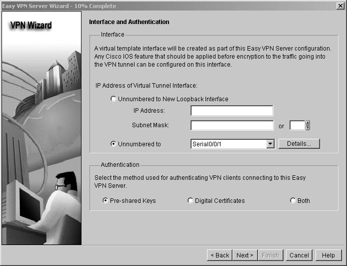
10 215

11 Step 3: Select an IKE proposal. a. In the IKE Proposals window, the default IKE proposal is used for R3. What is the encryption method used with the default IKE policy? What is the hash algorithm used to ensure that the keys have not been tampered with? b. Click Next to accept the default IKE policy. Note: Configurations on both sides of the tunnel must match exactly. The Cisco VPN Client automatically selects the proper configuration for itself. Therefore, an IKE configuration is not necessary on the client PC. 216

12 Step 4: Select the transform set. a. In the Transform Set window, the default SDM transform set is used. What ESP encryption method is used with the default transform set? b. Click Next to accept the default transform set. 217

13 Step 5: Specify group authorization and group policy lookup. a. In the Group Authorization and Group Policy Lookup window, select the Local option. b. Click Next to create a new AAA method list for group policy lookup that uses the local router database. 218

14 Step 6: Configure user authentication (XAuth). a. In the User Authentication (Xauth) window, you can specify to store user information on an external server, such as a RADIUS server or a local database, or both. Select the Enable User Authentication check box and accept the default of Local Only. Where does the router look for valid user accounts and passwords to authenticate remote VPN users when they attempt to log in? b. Click the Add User Credentials button. In the User Accounts window, you can view currently defined users or add new users. What is the name of the user currently defined and what is the user privilege level? How was this user defined? 219


15 c. In the User Accounts window, click the Add button to add another user. Enter the username VPNuser1 with a password of VPNuser1pass. Select the check box for encrypting the password using the MD5 hash algorithm. Leave the privilege level at 1. What is the range of privilege level that can be set for a user? d. Click OK to accept the VPNuser1 entries, and then click OK to close the User Accounts window. e. In the User Authentication (XAuth) window, click Next to continue. 220

16 Step 7: Specify group authorization and user group policies. In the Group Authorization and User Group Policies window, you must create at least one group policy for the VPN server. a. Click Add to create a group policy. b. In the Add Group Policy window, enter VPN-Access as the name of this group. Enter a new preshared key of cisco12345 and then re-enter it. c. Leave the Pool Information box checked and enter a starting address of , an ending address of , and a subnet mask of d. Enter 50 for the Maximum Connections Allowed. e. Click OK to accept the entries. 221
.")
17 f. An SDM warning message displays indicating that the IP addresses in the pool and the IP address of the FastEthernet0/1 interface are in the same subnet. Click Yes to continue. g. When you return to the Group Authorization window, check the Configure Idle Timer check box and enter one hour (1). This disconnects idle users if there is no activity for one hour and allows others to connect. Click Next to continue. 222

18 h. When the Cisco Tunneling Control Protocol (ctcp) window displays, do not enable ctcp. Click Next to continue. i. When the Easy VPN Server Passthrough Configuration window displays, make sure that the Action Modify check box is checked. This option allows SDM to modify the firewall on S0/0/1 to allow IPsec VPN traffic to reach the internal LAN. Click OK to continue. 223


19 Step 8: Review the configuration summary and deliver the commands. a. Scroll through the commands that SDM will send to the router. Do not check the check box to test the VPN. Click Finish. b. When prompted to deliver the configuration to the router, click Deliver. c. In the Command Delivery Status window, click OK. How many commands are delivered? 224

20 Step 9: Test the VPN Server. a. You are returned to the main VPN window with the Edit Easy VPN Server tab selected. Click the Test VPN Server button in the lower right corner of the screen. b. In the VPN Troubleshooting window, click the Start button. c. Your screen should look similar to the one below. Click OK to close the information window. Click Close to exit the VPN Troubleshooting window. 225

 on it. b.")
21 Task 4. Use the Cisco VPN Client to Test the Remote Access VPN Step 1: (Optional) Install the Cisco VPN client. If the Cisco VPN Client software on host PC-A is not installed, install it now. If you do not have the Cisco VPN Client software, contact your instructor. Step 2: Configure PC-A as a VPN client to access the R1 VPN server. a. Start the Cisco VPN Client and select Connection Entries > New, or click the New icon with the red plus sign (+) on it. b. Enter the following information to define the new connection entry. Click Save when you are finished. 226
 Group Authentication Name: VPN-Access (defines the address pool configured in Task 2) Password: cisco12345 (pre-shared key configured in Task 2) Confirm")
22 Connection Entry: VPN-R3 Description: Connection to R3 internal network Host: (IP address of the R3 S0/0/1 interface) Group Authentication Name: VPN-Access (defines the address pool configured in Task 2) Password: cisco12345 (pre-shared key configured in Task 2) Confirm Password: cisco12345 Note: The group authentication name and password are case-sensitive and must match the ones created on the VPN Server. Step 3: Test access from PC-A without a VPN connection. In the previous step, you created a VPN connection entry on the VPN client computer PC-A but have not activated it, so the VPN tunnel is not yet up. Open a command prompt on PC-A and ping the PC-C IP address at on the R3 LAN. Are the pings successful? Why or why not? Step 4: Establish a VPN connection and log in. a. Select the newly created connection VPN-R3 and click the Connect icon. You can also double-click the connection entry. 227


23 b. Enter the previously created username VPNuser1 in the VPN Client User Authentication dialog box and enter the password VPNuser1pass. Click OK to continue. The VPN Client window minimizes to a lock icon in the tools tray of the taskbar. When the lock is closed, the VPN tunnel is up. When it is open, the VPN connection is down. Task 5. Verify the VPN Tunnel Between the Client, Server, and Internal Network Step 1: Open the VPN Client icon. a. Double-click the VPN lock icon to expand the VPN Client window. What does it say about the connection status at the top of the window? b. From the PC-A command line, issue the ipconfig command. What is the IP address of the first Local Area Connection? What is the IP address of Local Area Connection 2? Step 2: Close the VPN connection and reopen it. a. Click the Disconnect icon in the VPN Client window to close the VPN-R3 connection. b. Click the Connect icon and log in again as VPNuser1. 228

24 What is the IP address of Local Area Connection 2 now? Note: Each time you disconnect and reconnect to the VPN server, you receive a new IP address until the limit is reached. Step 3: Check the tunnel statistics. a. Select Status > Statistics. Click the Tunnel Details tab. b. What is the current address obtained from the R3 VPN server and what is the range of addresses that can be assigned? What is the VPN server address? How many packets have been encrypted? What is the encryption method? What is the authentication method? c. Leave the VPN Client Statistics window open. Step 4: Test access from the client PC-A using the VPN connection. With the VPN connection from computer PC-A to router R3 activated, open a command prompt on PC-A and ping the PC-C IP address at on the R3 LAN. Are the pings successful? Why or why not? How many packets have now been encrypted? 229
25 Step 5: Check the Cisco IOS message on R3 when the tunnel is created. Open the console connection for R3 and locate the message displayed indicating that the virtual interface came up when the VPN Client connection was made. What is the name of the interface on R3 that is activated for the VPN? Step 6: Verify the VPN connection information for PC-A. From the PC-A command prompt, issue the ipconfig /all command to see the network connections. a. What is the configuration for the first Local Area Connection? IP Address: Subnet Mask: Default Gateway: Description: b. What is the configuration for Local Area Connection 2? IP Address: Subnet Mask: Default Gateway: Description: Step 7: Telnet from PC-A to R3. From the PC-A command prompt, telnet to R3 at the Fa0/1 IP address Log in as admin01 with a password of admin01pass. What is the router command prompt and why is this? a. Issue the show run command to view the various commands generated by SDM to configure the VPN Server. b. Issue the show users command to see connections to router R3. What connections are present? c. Close the Telnet connection using the quit or exit command. Task 6. Reflection Why is VPN a good option for remote users? Router Interface Summary Table Router Interface Summary Router Model Ethernet Interface #1 Ethernet Interface #2 Serial Interface #1 Serial Interface # Fast Ethernet 0 (FA0) Fast Ethernet 1 (FA1) Serial 0 (S0) Serial 1 (S1) 1800 Fast Ethernet 0/0 (FA0/0) Fast Ethernet 0/1 (FA0/1) Serial 0/0/0 (S0/0/0) Serial 0/0/1 (S0/0/1) 2600 Fast Ethernet 0/0 (FA0/0) Fast Ethernet 0/1 (FA0/1) Serial 0/0 (S0/0) Serial 0/1 (S0/1) 230
26 2800 Fast Ethernet 0/0 (FA0/0) Router Interface Summary Fast Ethernet 0/1 (FA0/1) Serial 0/0/0 (S0/0/0) Serial 0/0/1 (S0/0/1) Note: To find out how the router is configured, look at the interfaces to identify the type of router and how many interfaces the router has. There is no way to effectively list all the combinations of configurations for each router class. This table includes identifiers for the possible combinations of Ethernet and Serial interfaces in the device. The table does not include any other type of interface, even though a specific router may contain one. An example of this might be an ISDN BRI interface. The string in parenthesis is the legal abbreviation that can be used in Cisco IOS commands to represent the interface. 231
Chapter 10 Configure AnyConnect Remote Access SSL VPN Using ASDM
 Chapter 10 Configure AnyConnect Remote Access SSL VPN Using ASDM Topology Note: ISR G1 devices use FastEthernet interfaces instead of GigabitEthernet interfaces. 2015 Cisco and/or its affiliates. All rights
Lab - Examining Telnet and SSH in Wireshark
 Topology Addressing Table Objectives Device Interface IP Address Subnet Mask Default Gateway R1 G0/1 192.168.1.1 255.255.255.0 N/A PC-A NIC 192.168.1.3 255.255.255.0 192.168.1.1 Part 1: Configure the Devices
Lab 7 Configuring Basic Router Settings with IOS CLI
 Lab 7 Configuring Basic Router Settings with IOS CLI Objectives Part 1: Set Up the Topology and Initialize Devices Cable equipment to match the network topology. Initialize and restart the router and switch.
Lab Configuring and Verifying Extended ACLs Topology
 Topology 2015 Cisco and/or its affiliates. All rights reserved. This document is Cisco Public. Page 1 of 8 Addressing Table Objectives Device Interface IP Address Subnet Mask Default Gateway R1 G0/1 192.168.10.1
Lab Using the CLI to Gather Network Device Information Topology
 Topology Addressing Table Objectives Device Interface IP Address Subnet Mask Default Gateway R1 G0/1 192.168.1.1 255.255.255.0 N/A Lo0 209.165.200.225 255.255.255.224 N/A S1 VLAN 1 192.168.1.11 255.255.255.0
Chapter 10 Configure Clientless Remote Access SSL VPNs Using ASDM
 Chapter 10 Configure Clientless Remote Access SSL VPNs Using ASDM This lab has been updated for use on NETLAB+ Topology Note: ISR G1 devices use FastEthernet interfaces instead of GigabitEthernet Interfaces.
Lab - Securing Administrative Access Using AAA and RADIUS
 CCNA Security Lab - Securing Administrative Access Using AAA and RADIUS Topology Note: ISR G1 devices use FastEthernet interfaces instead of GigabitEthernet Interfaces. 2015 Cisco and/or its affiliates.
Chapter 10 Configure Clientless Remote Access SSL VPNs Using ASDM
 Chapter 10 Configure Clientless Remote Access SSL VPNs Using ASDM Topology Note: ISR G1 devices use FastEthernet interfaces instead of GigabitEthernet Interfaces. 2016 Cisco and/or its affiliates. All
Lab Correcting RIPv2 Routing Problems
 Lab 9.4.2 Correcting RIPv2 Routing Problems e Interface IP Address Subnet Mask Default Gateway Device Host Name Interface IP Address Subnet Mask Default Gateway R1 BRANCH1 Fast Ethernet 0/0 172.16.0.1
Chapter 10 - Configure ASA Basic Settings and Firewall using ASDM
 Chapter 10 - Configure ASA Basic Settings and Firewall using ASDM This lab has been updated for use on NETLAB+ Topology Note: ISR G1 devices use FastEthernet interfaces instead of GigabitEthernet interfaces.
Lab Configuring Switch Security Features Topology
 Topology Addressing Table Objectives Device Interface IP Address Subnet Mask Default Gateway R1 G0/1 172.16.99.1 255.255.255.0 N/A S1 VLAN 99 172.16.99.11 255.255.255.0 172.16.99.1 PC-A NIC 172.16.99.3
Lab Troubleshooting Basic PPP with Authentication Topology
 Topology 2013 Cisco and/or its affiliates. All rights reserved. This document is Cisco Public. Page 1 of 8 Addressing Table Objectives Device Interface IP Address Subnet Mask Default Gateway R1 G0/1 192.168.1.1
Lab - Troubleshooting Standard IPv4 ACL Configuration and Placement Topology
 Lab - Troubleshooting Standard IPv4 ACL Configuration and Placement Topology 2016 Cisco and/or its affiliates. All rights reserved. This document is Cisco Public. Page 1 of 8 Addressing Table Objectives
Lab Securing Network Devices
 Topology Addressing Table Objectives Device Interface IP Address Subnet Mask Default Gateway R1 G0/1 192.168.1.1 255.255.255.0 N/A S1 VLAN 1 192.168.1.11 255.255.255.0 192.168.1.1 PC-A NIC 192.168.1.3
Skills Assessment Student Practice
 Skills Assessment Student Practice Topology Assessment Objectives Part 1: Develop the IPv4 Address Scheme (15 points, 20 minutes) Part 2: Initialize and Reload Devices (10 points, 5 minutes) Part 3: Configure
Lab Configuring and Verifying Standard IPv4 ACLs Topology
 Topology 2016 Cisco and/or its affiliates. All rights reserved. This document is Cisco Public. Page 1 of 10 Addressing Table Objectives Device Interface IP Address Subnet Mask Default Gateway R1 G0/1 192.168.10.1
Skills Assessment Student Training Exam
 Skills Assessment Student Training Exam Time: 20 minutes Given an IP address and mask of (address / mask), design an IP addressing scheme that satisfies the following requirements. Network address/mask
Lab Configuring Dynamic and Static NAT (Solution)
") (Solution) Topology Addressing Table Objectives Device Interface IP Address Subnet Mask Default Gateway Gateway G0/1 192.168.1.1 255.255.255.0 N/A S0/0/1 209.165.201.18 255.255.255.252 N/A ISP S0/0/0 (DCE)
(Solution) Topology Addressing Table Objectives Device Interface IP Address Subnet Mask Default Gateway Gateway G0/1 192.168.1.1 255.255.255.0 N/A S0/0/1 209.165.201.18 255.255.255.252 N/A ISP S0/0/0 (DCE)
Retake - Skills Assessment Student Training (Answer Key)
") Retake - Skills Assessment Student Training (Answer Key) Name:. Topology Assessment Objectives Part 1: Develop the IPv4 Address Scheme (15 points, 0 minutes) Part 2: Configure Device IPv4 and Security
Retake - Skills Assessment Student Training (Answer Key) Name:. Topology Assessment Objectives Part 1: Develop the IPv4 Address Scheme (15 points, 0 minutes) Part 2: Configure Device IPv4 and Security
Lab Configuring Dynamic and Static NAT (Instructor Version Optional Lab)
") (Instructor Version Optional Lab) Instructor Note: Red font color or gray highlights indicate text that appears in the instructor copy only. Optional activities are designed to enhance understanding and/or
(Instructor Version Optional Lab) Instructor Note: Red font color or gray highlights indicate text that appears in the instructor copy only. Optional activities are designed to enhance understanding and/or
Lab - Building a Switch and Router Network
 Topology Addressing Table Device Interface IP Address Subnet Mask Default Gateway G0/0 192.168.0.1 N/A G0/1 192.168.1.1 N/A PC-A NIC 192.168.1.3 192.168.1.1 PC-B NIC 192.168.0.3 192.168.0.1 R1 Objectives
Lab Configuring Basic RIPv2 (Solution)
") (Solution) Topology 2017 Cisco and/or its affiliates. All rights reserved. This document is Cisco Public. Page 1 of 15 Addressing Table Objectives Device Interface IP Address Subnet Mask Default Gateway
(Solution) Topology 2017 Cisco and/or its affiliates. All rights reserved. This document is Cisco Public. Page 1 of 15 Addressing Table Objectives Device Interface IP Address Subnet Mask Default Gateway
Lab Configuring Port Address Translation (PAT) Topology
 Topology") Topology Addressing Table Objectives Device Interface IP Address Subnet Mask Default Gateway Gateway G0/1 192.168.1.1 255.255.255.0 N/A S0/0/1 209.165.201.18 255.255.255.252 N/A ISP S0/0/0 (DCE) 209.165.201.17
Topology Addressing Table Objectives Device Interface IP Address Subnet Mask Default Gateway Gateway G0/1 192.168.1.1 255.255.255.0 N/A S0/0/1 209.165.201.18 255.255.255.252 N/A ISP S0/0/0 (DCE) 209.165.201.17
Skills Assessment Student Training
 Skills Assessment Student Training Topology Assessment Objectives Part 1: Initialize Devices (6 points, 5 minutes) Part 2: Configure Device Basic Settings (33 points, 20 minutes) Part 3: Configure Switch
PT Activity: Configure AAA Authentication on Cisco Routers
 PT Activity: Configure AAA Authentication on Cisco Routers Instructor Version Topology Diagram Addressing Table Device Interface IP Address Subnet Mask R1 Fa0/0 192.168.1.1 255.255.255.0 S0/0/0 10.1.1.2
This document is exclusive property of Cisco Systems, Inc. Permission is granted to print and copy this document for non-commercial distribution and
 This document is exclusive property of Cisco Systems, Inc. Permission is granted to print and copy this document for non-commercial distribution and exclusive use by instructors in the CCNA Exploration:
Lab - Troubleshooting ACL Configuration and Placement Topology
 Topology 2015 Cisco and/or its affiliates. All rights reserved. This document is Cisco Public. Page 1 of 8 Addressing Table Objectives Device Interface IP Address Subnet Mask Default Gateway HQ G0/1 192.168.1.1
Lab Configuring HSRP and GLBP Topology
 Topology 2014 Cisco and/or its affiliates. All rights reserved. This document is Cisco Public. Page 1 of 9 Addressing Table Objectives Device Interface IP Address Subnet Mask Default Gateway R1 G0/1 192.168.1.1
Chapter 8: Lab A: Configuring a Site-to-Site VPN Using Cisco IOS
 Chapter 8: Lab A: Configuring a Site-to-Site VPN Using Cisco IOS Topology IP Addressing Table Device Interface IP Address Subnet Mask Default Gateway Switch Port R1 FA0/1 192.168.1.1 255.255.255.0 N/A
Device Interface IP Address Subnet Mask R1 G0/ N/A
 CSNB214 Packet Tracer Topology Addressing Table Device Interface IP Address Subnet Mask Default Gateway Objectives R1 G0/0 192.168.20.1 255.255.255.0 N/A S1 VLAN 10 S2 VLAN 10 G0/1 192.168.10.1 255.255.255.0
Lab Configuring Port Address Translation (PAT) (Instructor Version)
 (Instructor Version)") (Instructor Version) Instructor Note: Red font color or gray highlights indicate text that appears in the instructor copy only. Topology Addressing Table Objectives Device Interface IP Address Subnet Mask
(Instructor Version) Instructor Note: Red font color or gray highlights indicate text that appears in the instructor copy only. Topology Addressing Table Objectives Device Interface IP Address Subnet Mask
Lab Managing Router Configuration Files with Terminal Emulation Software
 Lab Managing Router Configuration Files with Terminal Emulation Software Topology Addressing Table Objectives Device Interface IP Address Subnet Mask Default Gateway R1 G0/1 192.168.1.1 255.255.255.0 N/A
Lab Configuring and Verifying Standard IPv4 ACLs (Instructor Version Optional Lab)
") (Instructor Version Optional Lab) Instructor Note: Red font color or gray highlights indicate text that appears in the instructor copy only. Optional activities are designed to enhance understanding and/or
(Instructor Version Optional Lab) Instructor Note: Red font color or gray highlights indicate text that appears in the instructor copy only. Optional activities are designed to enhance understanding and/or
Lab Configuring 802.1Q Trunk-Based Inter-VLAN Routing Topology
 Topology 2016 Cisco and/or its affiliates. All rights reserved. This document is Cisco Public. Page 1 of 7 Addressing Table Device Interface IP Address Subnet Mask Default Gateway R1 G0/1.1 192.168.1.1
TELECOMMUNICATION MANAGEMENT AND NETWORKS
 QUAID-E-AWAM UNIVERSITY OF ENGINEERING SCIENCE AND TECHNOLOGY, NAWABSHAH TELECOMMUNICATION MANAGEMENT AND NETWORKS LAB # 3 CONFIGURING INTERFACES OF ROUTER AND SWITCH Topology Diagram Addressing Table
Lab - Configuring Basic DHCPv4 on a Router (Solution)
") (Solution) Topology Addressing Table Objectives Device Interface IP Address Subnet Mask Default Gateway R1 G0/0 192.168.0.1 255.255.255.0 N/A G0/1 192.168.1.1 255.255.255.0 N/A S0/0/0 (DCE) 192.168.2.253
(Solution) Topology Addressing Table Objectives Device Interface IP Address Subnet Mask Default Gateway R1 G0/0 192.168.0.1 255.255.255.0 N/A G0/1 192.168.1.1 255.255.255.0 N/A S0/0/0 (DCE) 192.168.2.253
Lab - Configuring a Switch Management Address
 Topology Addressing Table Objectives Device Interface IP Address Subnet Mask Default Gateway S1 VLAN 1 192.168.1.2 255.255.255.0 N/A PC-A NIC 192.168.1.10 255.255.255.0 N/A Part 1: Configure a Basic Network
Chapter 4 Lab A: Configuring CBAC and Zone-Based Firewalls
 Chapter 4 Lab A: Configuring CBAC and Zone-Based Firewalls Topology Note: ISR G2 devices have Gigabit Ethernet interfaces instead of Fast Ethernet Interfaces. IP Addressing Table Device Interface IP Address
Cisco Network Academy CCNA 1 Introduction to Networks
 Cisco Network Academy CCNA 1 Introduction to Networks Packet Tracer Practice with Dans Sample http://www.danscourses.com/ In this lab, you will learn how to configure the following tasks: IPv4 Addressing
Lab Configuring an ISR with SDM Express
 Lab 5.2.3 Configuring an ISR with SDM Express Objectives Configure basic router global settings router name, users, and login passwords using Cisco SDM Express. Configure LAN and Internet connections on
Lab - Configuring Multi-area OSPFv2
 Topology Addressing Table Device Interface IP Address Subnet Mask Lo0 209.165.200.225 255.255.255.252 R1 R2 R3 Lo1 192.168.1.1 255.255.255.0 Lo2 192.168.2.1 255.255.255.0 S0/0/0 (DCE) 192.168.12.1 255.255.255.252
Lab - Troubleshooting DHCPv4 Topology
 Topology 2014 Cisco and/or its affiliates. All rights reserved. This document is Cisco Public. Page 1 of 9 Addressing Table Objectives Device Interface IP Address Subnet Mask Default Gateway R1 G0/0 192.168.0.1
CCNA Semester 2 labs. Labs for chapters 2 10
 CCNA Semester 2 labs Labs for chapters 2 10 2.2.2.5 Lab - Configuring IPv4 Static and Default Routes 2.3.2.4 Lab - Troubleshooting Static Routes 3.2.1.9 Lab - Configuring Basic RIPv2 5.2.2.9 Lab - Configuring
Lab 1.3.2: Review of Concepts from Exploration 1 - Challenge
 Lab 1.3.2: Review of Concepts from Exploration 1 - Challenge Topology Diagram Learning Objectives Upon completion of this lab, you will be able to: Create a logical topology given network requirements
Lab 2.8.1: Basic Static Route Configuration
 Topology Diagram Addressing Table Device Interface IP Address Subnet Mask Default Gateway R1 Fa0/0 172.16.3.1 255.255.255.0 N/A S0/0/0 172.16.2.1 255.255.255.0 N/A Fa0/0 172.16.1.1 255.255.255.0 N/A R2
KIM DONNERBORG / RTS. Cisco Lab Øvelse Af Kim Donnerborg / RTS. Side 0 af 8
 KIM DONNERBORG / RTS Side 0 af 8 INDHOLDSFORTEGNELSE Lab: Basic Router Configuration... 2 Topology Diagram... 2 Addressing Table... 2 Learning Objectives... 2 Scenario... 2 Task 1: Cable the Network....
Chapter 8 Lab Configuring a Site-to-Site VPN Using Cisco IOS
 Chapter 8 Lab Configuring a Site-to-Site VPN Using Cisco IOS Topology Note: ISR G1 devices use FastEthernet interfaces instead of GigabitEthernet interfaces. 2017 Cisco and/or its affiliates. All rights
Skills Assessment Student Training Exam
 Skills Assessment Student Training Exam Topology Assessment Objectives Part 1: Initialize Devices (2 points, 5 minutes) Part 2: Configure Device Basic Settings (18 points, 20 minutes) Part 3: Configure
Lab - Configuring IPv6 Addresses on Network Devices
 Topology Addressing Table Device Interface IPv6 Address Prefix Length Default Gateway Objectives R1 G0/0 2001:DB8:ACAD:A::1 64 N/A G0/1 2001:DB8:ACAD:1::1 64 N/A S1 VLAN 1 2001:DB8:ACAD:1::B 64 N/A PC-A
Lab Configuring 802.1Q Trunk-Based Inter-VLAN Routing (Instructor Version Optional Lab)
") (Instructor Version Optional Lab) Instructor Note: Red font color or gray highlights indicate text that appears in the instructor copy only. Optional activities are designed to enhance understanding and/or
(Instructor Version Optional Lab) Instructor Note: Red font color or gray highlights indicate text that appears in the instructor copy only. Optional activities are designed to enhance understanding and/or
Configuring an IPSec Tunnel Between a Cisco SA500 and the Cisco VPN Client
 Application Note Configuring an IPSec Tunnel Between a Cisco SA500 and the Cisco VPN Client This application note document provides information on how to configure an SA500 IPSec VPN Tunnel for remote
Lab Configuring and Verifying Standard ACLs Topology
 Topology 2013 Cisco and/or its affiliates. All rights reserved. This document is Cisco Public. Page 1 of 9 Addressing Table Objectives Device Interface IP Address Subnet Mask Default Gateway R1 G0/1 192.168.10.1
Lab : Challenge OSPF Configuration Lab. Topology Diagram. Addressing Table. Default Gateway. Device Interface IP Address Subnet Mask
 Topology Diagram Addressing Table Device Interface IP Address Subnet Mask Default Gateway Fa0/0 HQ S0/0/0 S0/0/1 Lo1 10.10.10.1 255.255.255.252 Fa0/0 Branch1 S0/0/0 S0/0/1 Fa0/0 Branch2 S0/0/0 S0/0/1 PC1
Lab - Configuring a Site-to-Site VPN Using Cisco IOS and CCP
 CCNA Security Lab - Configuring a Site-to-Site VPN Using Cisco IOS and CCP Topology Note: ISR G2 devices use GigabitEthernet interfaces instead of FastEthernet Interfaces. 2015 Cisco and/or its affiliates.
Packet Tracer - Configure Cisco Routers for Syslog, NTP, and SSH Operations (Instructor Version)
") Packet Tracer - Configure Cisco Routers for Syslog, NTP, and SSH Operations (Instructor Version) Instructor Note: Red font color or Gray highlights indicate text that appears in the instructor copy only.
Packet Tracer - Configure Cisco Routers for Syslog, NTP, and SSH Operations (Instructor Version) Instructor Note: Red font color or Gray highlights indicate text that appears in the instructor copy only.
Lab Configuring Per-Interface Inter-VLAN Routing (Solution)
") (Solution) Topology Addressing Table Objectives Device Interface IP Address Subnet Mask Default Gateway R1 G0/0 192.168.20.1 255.255.255.0 N/A G0/1 192.168.10.1 255.255.255.0 N/A S1 VLAN 10 192.168.10.11
(Solution) Topology Addressing Table Objectives Device Interface IP Address Subnet Mask Default Gateway R1 G0/0 192.168.20.1 255.255.255.0 N/A G0/1 192.168.10.1 255.255.255.0 N/A S1 VLAN 10 192.168.10.11
Lab Troubleshooting IPv4 and IPv6 Static Routes (Instructor Version Optional Lab)
") (Instructor Version Optional Lab) Instructor Note: Red font color or gray highlights indicate text that appears in the instructor copy only. Optional activities are designed to enhance understanding and/or
(Instructor Version Optional Lab) Instructor Note: Red font color or gray highlights indicate text that appears in the instructor copy only. Optional activities are designed to enhance understanding and/or
Device Interface IP Address Subnet Mask Default Gateway
 Topology Diagram Addressing Table Device Interface IP Address Subnet Mask Default Gateway BRANCH HQ ISP Fa0/0 172.20.1.129 255.255.255.128 N/A S0/0/0 172.20.1.1 255.255.255.128 N/A Fa0/0 172.20.0.129 255.255.255.128
Lab Designing and Implementing a VLSM Addressing Scheme. Topology. Objectives. Background / Scenario
 CSNB214 Packet Tracer Lab Designing and Implementing a VLSM Addressing Scheme Topology Objectives Part 1: Examine Network Requirements Part 2: Design the VLSM Address Scheme Part 3: Cable and Configure
Lab Configuring Per-Interface Inter-VLAN Routing (Instructor Version)
") (Instructor Version) Instructor Note: Red font color or Gray highlights indicate text that appears in the instructor copy only. Topology Addressing Table Objectives Device Interface IP Address Subnet Mask
(Instructor Version) Instructor Note: Red font color or Gray highlights indicate text that appears in the instructor copy only. Topology Addressing Table Objectives Device Interface IP Address Subnet Mask
Lab Configuring IPv4 Static and Default Routes (Solution)
") (Solution) Topology Addressing Table Device Interface IP Address Subnet Mask Default Gateway R1 G0/1 192.168.0.1 255.255.255.0 N/A S0/0/1 10.1.1.1 255.255.255.252 N/A R3 G0/1 192.168.1.1 255.255.255.0
(Solution) Topology Addressing Table Device Interface IP Address Subnet Mask Default Gateway R1 G0/1 192.168.0.1 255.255.255.0 N/A S0/0/1 10.1.1.1 255.255.255.252 N/A R3 G0/1 192.168.1.1 255.255.255.0
Lab 5.6.2: Challenge RIP Configuration
 Topology Diagram Addressing Table Device Interface IP Address Subnet Mask Default Gateway BRANCH HQ ISP PC1 PC2 PC3 Fa0/0 S0/0/0 Fa0/0 S0/0/0 S0/0/1 Fa0/0 S0/0/1 NIC NIC NIC Learning Objectives Upon completion
Lab 9.6.2: Challenge EIGRP Configuration Lab
 Topology Diagram Addressing Table Device Interface IP Address Subnet Mask Default Gateway HQ BRANCH1 BRANCH2 PC1 PC2 PC3 Fa0/0 S0/0/0 S0/0/1 Lo1 Fa0/0 S0/0/0 S0/0/1 Fa0/0 S0/0/0 S0/0/1 NIC NIC NIC All
Lab 2.8.2: Challenge Static Route Configuration
 Topology Diagram Addressing Table Device Interface IP Address Subnet Mask Default Gateway BRANCH HQ ISP PC1 PC2 Web Server Fa0/0 S0/0/0 Fa0/0 S0/0/0 S0/0/1 209.165.201.2 255.255.255.252 Fa0/0 209.165.200.225
Lab Well-Known Port Numbers and Multiple Sessions
 Lab 10.2.5 Well-Known Port Numbers and Multiple Sessions Objective Enable HTTP services on a router. Show multiple HTTP and Telnet sessions on a single host. Observe well-known TCP port numbers on the
Skills Assessment (OSPF) Student Training Exam
 Student Training Exam") Skills Assessment (OSPF) Student Training Exam Topology 2013 Cisco and/or its affiliates. All rights reserved. This document is Cisco Public. Page 1 of 17 Addressing Table Assessment Objectives Device
Skills Assessment (OSPF) Student Training Exam Topology 2013 Cisco and/or its affiliates. All rights reserved. This document is Cisco Public. Page 1 of 17 Addressing Table Assessment Objectives Device
Default Gateway Fa0/ N/A. Device Interface IP Address Subnet Mask
 Felix Rohrer Topology Addressing Table Device Interface IP Address Subnet Mask Default Gateway Fa0/1 10.0.0.1 255.255.255.128 N/A S0/0/0 172.16.0.1 255.255.255.252 N/A S0/0/1 172.16.0.9 255.255.255.252
Skills Assessment (EIGRP) Student Training Exam
 Student Training Exam") Skills Assessment (EIGRP) Student Training Exam Topology 2013 Cisco and/or its affiliates. All rights reserved. This document is Cisco Public. Page 1 of 16 Addressing Table Assessment Objectives Device
Skills Assessment (EIGRP) Student Training Exam Topology 2013 Cisco and/or its affiliates. All rights reserved. This document is Cisco Public. Page 1 of 16 Addressing Table Assessment Objectives Device
Lab Troubleshooting RIP
 Lab 7.2.6 Troubleshooting RIP Objective Set up an IP addressing scheme using class B networks. Configure RIP on routers. Observe routing activity using the debug ip rip command. Examine routes using the
CCNA Security 1.0 Student Packet Tracer Manual
 1.0 Student Packet Tracer Manual This document is exclusive property of Cisco Systems, Inc. Permission is granted to print and copy this document for non-commercial distribution and exclusive use by instructors
SEMESTER 2 Chapter 1 Planning and Cabling a Network V 4.0
 SEMESTER 2 Chapter 1 Planning and Cabling a Network V 4.0 135 points 1.1.1 What are the common components between a router and other computers? CPU RAM ROM Operating System 1.1.1.2 What does a router connect?
Lab Configuring Basic Router Settings with IOS CLI (Instructor Version Optional Lab)
") (Instructor Version Optional Lab) Instructor Note: Red font color or gray highlights indicate text that appears in the instructor copy only. Optional activities are designed to enhance understanding and/or
(Instructor Version Optional Lab) Instructor Note: Red font color or gray highlights indicate text that appears in the instructor copy only. Optional activities are designed to enhance understanding and/or
Lab: Basic Static Route Configuration
 Lab: Basic Static Route onfiguration Topology Diagram Addressing Table Device Interface IP Address Subnet Mask Default Gateway R1 Fa0/0 172.16.3.1 255.255.255.0 N/A S0/0/0 172.16.2.1 255.255.255.0 N/A
Lab 7.5.1: Basic Wireless Configuration
 Topology Diagram Learning Objectives Configure options in the Linksys Setup tab. Configure options in the Linksys Wireless tab. Configure options in the Linksys Administration tab. Configure options in
Lab 1.1.4c Configuring Static NAT Addresses
 Lab 1.1.4c Configuring Static NAT Addresses Objective Configure a router to use network address translation (NAT) to convert internal IP addresses, typically private addresses, into outside public addresses.
Lab Configuring Advanced EIGRP for IPv4 Features Topology
 Topology 2017 Cisco and/or its affiliates. All rights reserved. This document is Cisco Public. Page 1 of 9 Addressing Table Device Interface IP Address Subnet Mask Default Gateway G0/0 192.168.1.1 255.255.255.0
Lab Troubleshooting VTP Configuration
 Lab 4.4.3 Troubleshooting VTP Configuration Topology Diagram Addressing Table Device (Hostname) Interface IP Address Subnet Mask S1 VLAN 99 172.17.99.11 255.255.255.0 S2 VLAN 99 172.17.99.12 255.255.255.0
Lab Troubleshooting WAN Connectivity
 Lab 9.2.5 Troubleshooting WAN Connectivity Device Host Name Interface IP Address Subnet Mask Default Gateway R1 R1 Fast Ethernet 0/0 192.168.1.1 255.255.255.0 N/A Serial 0/0/0 (DCE) 192.168.3.1 255.255.255.252
Hochschule Bremen Networking Lab
 Hochschule Bremen Networking Lab User Manual Welcome to the Hochschule Bremen networking lab. This manual will give you a brief introduction on how to use the PCs and networking hardware in the lab. The
Lab - Configuring & Troubleshooting Basic DHCPv4 on a Router
 Lab - Configuring & Troubleshooting Basic DHCPv4 on a Router Topology Addressing Table Objectives Device Interface IP Address Subnet Mask Default Gateway R1 G0/0 192.168.0.1 255.255.255.0 N/A G0/1 192.168.1.1
Lab AAA Authorization and Accounting
 Lab 11.3.2 AAA Authorization and Accounting Objective Scenario Step 1 In this lab, the student will use the exec-timeout command to control the amount of time before an idle telnet or console session is
PT Activity: Configuring a Zone-Based Policy Firewall (ZPF)
") PT Activity: Configuring a Zone-Based Policy Firewall (ZPF) Instructor Version Topology Diagram Addressing Table Device Interface IP Address Subnet Mask Default Gateway R1 R2 R3 Fa0/1 192.168.1.1 255.255.255.0
PT Activity: Configuring a Zone-Based Policy Firewall (ZPF) Instructor Version Topology Diagram Addressing Table Device Interface IP Address Subnet Mask Default Gateway R1 R2 R3 Fa0/1 192.168.1.1 255.255.255.0
Lab Verifying NAT and PAT Configuration
 Lab 1.1.5 Verifying NAT and PAT Configuration Objective Configure a router for Network Address Translation (NAT) and Port Address Translation (PAT) Test the configuration and verify NAT/PAT statistics
Lab Student Lab Orientation
 Lab 1.1.1 Student Lab Orientation Objective In this lab, the students will complete the following tasks: Review the lab bundle equipment Understand the security pod topology Understand the pod naming and
Lab 4.2.5a Connectivity Tests Ping
 Lab 4.2.5a Connectivity Tests Ping Objective Use the ping command to send ICMP datagrams to target host. Verify that the network layer between source and destination is working properly. Retrieve information
Lab Configuring Router Passwords. Objective. Background/Preparation. Step 1 Login to the router in user EXEC mode
 Lab 3.1.3 Configuring Router Passwords Objective Configure a password for console login to user EXEC mode. Configure a password for virtual terminal (Telnet) sessions. Configure a secret password for privileged
8.9.2 Lab: Configure an Ethernet NIC to use DHCP in Windows Vista
 8.9.2 Lab: Configure an Ethernet NIC to use DHCP in Windows Vista Introduction If Vista is not available in your classroom, you may complete this lab by viewing the figures in this document. Print and
Lab Configuring Basic Switch Settings (Solution)
") (Solution) Topology Addressing Table Objectives Device Interface IP Address Subnet Mask Default Gateway S1 VLAN 99 192.168.1.2 255.255.255.0 192.168.1.1 PC-A NIC 192.168.1.10 255.255.255.0 192.168.1.1
(Solution) Topology Addressing Table Objectives Device Interface IP Address Subnet Mask Default Gateway S1 VLAN 99 192.168.1.2 255.255.255.0 192.168.1.1 PC-A NIC 192.168.1.10 255.255.255.0 192.168.1.1
Chapter 10 Lab B: Configuring ASA Basic Settings and Firewall Using ASDM
 Chapter 10 Lab B: Configuring ASA Basic Settings and Firewall Using ASDM Topology Note: ISR G2 devices have Gigabit Ethernet interfaces instead of Fast Ethernet interfaces. All contents are Copyright 1992
Chapter 2: Lab A: Securing the Router for Administrative Access
 Chapter 2: Lab A: Securing the Router for Administrative Access Topology IP Addressing Table Device Interface IP Address Subnet Mask Default Gateway Switch Port R1 FA0/1 192.168.1.1 255.255.255.0 N/A S1
Packet Tracer - Configure and Verify a Site-to-Site IPsec VPN Using CLI
 Packet Tracer - Configure and Verify a Site-to-Site IPsec VPN Using CLI Topology Addressing Table R1 R2 R3 Device Interface IP Address Subnet Mask Default Gateway Switch Port G0/0 192.168.1.1 255.255.255.0
Skills Assessment (OSPF) Student Training Exam
 Student Training Exam") Skills Assessment (OSPF) Student Training Exam Topology Cisco and/or its affiliates. All rights reserved. This document is Cisco Public. Page 1 of 16 Addressing Table Device Interface IP Address Subnet
Skills Assessment (OSPF) Student Training Exam Topology Cisco and/or its affiliates. All rights reserved. This document is Cisco Public. Page 1 of 16 Addressing Table Device Interface IP Address Subnet
Lab Configuring DHCP
 Lab 1.2.6 Configuring DHCP Objective Configure a router for Dynamic Host Configuration Protocol (DHCP) to dynamically assign addresses to attached hosts. Background/Preparation Routing between the ISP
CCNA Security PT Practice SBA
 A few things to keep in mind while completing this activity: 1. Do not use the browser Back button or close or reload any Exam windows during the exam. 2. Do not close Packet Tracer when you are done.
Lab 2.5.1: Basic PPP Configuration Lab
 Topology Diagram Addressing Table Device Interface IP Address Subnet Mask R1 R2 R3 Default Gateway Fa0/1 192.168.10.1 255.255.255.0 N/A S0/0/0 10.1.1.1 255.255.255.252 N/A Lo0 209.165.200.225 255.255.255.224
Lab Troubleshooting IP Address Issues Instructor Version 2500
 Lab 4.2.6 Troubleshooting IP Address Issues Instructor Version 2500 Objective Configure two routers and two workstations in a small WAN. Troubleshoot problems introduced by incorrect configurations. Background/Preparation
Lab 1.1.4a Configuring NAT
 Lab 1.1.4a Configuring NAT Objective Configure a router to use network address translation (NAT) to convert internal IP addresses, typically private addresses, into outside public addresses. Background/Preparation
Lab - Troubleshooting VLAN Configurations (Instructor Version Optional Lab)
") (Instructor Version Optional Lab) Instructor Note: Red font color or gray highlights indicate text that appears in the instructor copy only. Optional activities are designed to enhance understanding and/or
(Instructor Version Optional Lab) Instructor Note: Red font color or gray highlights indicate text that appears in the instructor copy only. Optional activities are designed to enhance understanding and/or
Before you start the lab exercises see the lab administrator or EEE3080F tutor to get assigned to your routers.
 EEE00F Lab Basics of the Network Lab Student Lab Manual Before you start the lab exercises see the lab administrator or EEE00F tutor to get assigned to your routers. Contents. Resources used in the labs...
NETWORK LAB 2 Configuring Switch Desktop
 Configuring Switch 1. Select the switch tab and then add a switch from the list of switches we have to the workspace, we will choose (2950-24) switch. 2. Add a number of PCs next to the switch in order