IEEE a+g WLAN Router USER S GUIDE
|
|
|
- Herbert McDowell
- 6 years ago
- Views:
Transcription
1 IEEE a+g WLAN Router USER S GUIDE VERSION 2.0, JULY. 2004
2 Copyright Statement No part of this publication may be reproduced, stored in a retrieval system, or transmitted in any form or by any means, whether electronic, mechanical, photocopying, recording or otherwise without the prior writing of the publisher. Windows 95/98/Me and Windows 2000 are trademarks of Microsoft Corp. Pentium is trademark of Intel. All copyright is reserved. 1
3 TABLE OF CONTENT INTRODUCING THE A+G ROUTER... 3 OVERVIEW OF THE A+G ROUTER A+G ROUTER APPLICATIONS... 4 A SECURITY OVERVIEW A+G ROUTER FEATURES... 6 SETTING UP THE DEVICE... 6 INSTALLING THE A+G ROUTER... 7 WHAT S IN THE BOX?... 7 A PHYSICAL LOOK AT THE BACK PANEL... 8 A PHYSICAL LOOK AT THE FRONT PANEL... 9 CONNECTING THE CABLES HIGH LEVEL CONFIGURATION STEPS REQUIRED FOR THE A+G ROUTER SETTING UP A WINDOWS PC OR WIRELESS CLIENT AS DHCP CLIENTS CONFIGURING A PC RUNNING MS-WINDOWS 95/98/ME: CONFIGURING A PC RUNNING MS-WINDOWS XP/2000: CONFIRMING YOUR PC S IP CONFIGURATION: CONNECTING MORE DEVICES THROUGH A HUB TO THE A+G ROUTER BASIC CONFIGURATION OF THE A+G ROUTER LOGGING ON SETUP WIZARD ADVANCED SETTINGS OPERATIONAL MODE PASSWORD SETTINGS SYSTEM MANAGEMENT SNMP SETTINGS DHCP SERVER SETTINGS MULTIPLE DMZ VIRTUAL SERVER SETTINGS SPECIAL APPLICATIONS MAC FILTERING SETTINGS IP FILTERING SETTINGS IP ROUTING SETTINGS WIRELESS SETTINGS RADIUS SETTINGS DYNAMIC DNS SETTINGS MANAGING YOUR A+G ROUTER HOW TO VIEW THE DEVICE STATUS HOW TO VIEW THE SYSTEM LOG DHCP CLIENT TABLE WIRELESS CLIENT TABLE BRIDGE TABLE RADIO TABLE UPGRADING FIRMWARE HOW TO SAVE OR RESTORE CONFIGURATION CHANGES HOW TO REBOOT YOUR A+G ROUTER WHAT IF YOU FORGOT THE PASSWORD? SPECIFICATION
4
5 Introducing the a+g Router This manual gives a basic introduction to a+g Wireless Router. It provides information to configure the a+g Router to operate in common applications such as connecting to the Internet. Chapter 1 We ll describe how to use your web browser to configure the a+g Router and to perform various management functions, e.g. upgrading the software, or viewing the system log, a task that can be useful in ongoing operations. This manual consists of the following chapters and appendixes: Chapter One, Introduction, summarizes features and capabilities of the a+g Router. Chapter Two, Installing the a+g Router, gives steps you should follow to install the a+g Router and configure your PCs. Chapter Three, Configuring the a+g Router, describes how to log in to the Web Manager, the browser screen, and steps needed to configure your a+g Router for specific applications. It gives easy-to-follow instructions for quick Internet access and provides a guide to basic a+g Router configuration. Chapter Four, Advanced Configuration, provides information on advanced router configuration. Chapter Five, Managing your a+g Router, explains other management features of the a+g Router. 3
. The 802.")
6 Overview of the a+g Router The a+g Router is a small desktop router that sits between your local Ethernet network and a remote network (e.g., the Internet). The a+g Router contains a WAN port connecting to an external ADSL/Cable modem, a four-port 10/100Mbps Ethernet switch for connection to PCs on your local wired network, and two wireless interfaces for connection to your local wireless network: one supports a, another can be configured to support either both b and g or g only (both radios support a data rate of up to 54 Mbps). Data comes into the a+g Router from the local wired and wireless LAN and then is routed to the Internet, and vice versa a+g Router Applications ACCESSING THE INTERNET The most common use of the a+g Router is to provide shared Internet access to allow everyone on your LAN to surf the web and send/receive s or files. The a+g Router can automatically acquire a public IP address when connecting to the Internet. In turn, it will automatically assign IP addresses to PCs (requesting DHCP client devices) on your LAN - you don t have to apply for and assign IP addresses to PCs on your network. ACCESSING SERVERS FROM THE PUBLIC NETWORK If you want special servers to be accessible to remote users across the Internet (e.g., an server, an FTP server, or a web server), you can configure the a+g Router to proxy the service using its (public) IP address. It means a remote user can access the server by using the a+g Router s IP address. Upon receiving a request, the a+g Router will re-direct the request to the actual server on your local network. OPERATING AS AN ACCESS POINT Additionally, the Wireless Router can also be configured as an Access Point, and acts as the central point of your local wireless network supporting a data rate of up to 54 Mbps. It allows client devices on 4
7 your wireless network to access the Internet, to communicate with other wireless devices on your wireless network, or to communicate with devices on your wired LAN network. Since g is based on the same 2.4GHz radio band as the b technology, the a+g Router can inter-operate with existing 11Mbps b devices. Therefore you can protect your existing investment in b client cards, and migrate to the high-speed g standard as your needs grow. Besides, the a+g Router also provides connection to a client devices. It can provide both a and b/g connections simultaneously. A Security Overview More and more people are concerned about protecting your local network from the Internet. The a+g Router provides several ways to keep your network secure: Devices on your wired or wireless network are assigned private IP addresses; therefore remote users from the Internet cannot see nor access them. The a+g Router implements IP packet filtering with SPI (Stateful Packet Inspection) capabilities, which you can use to selectively filter (discard) packets to/from the Internet. You can selectively restrict management from remote devices. To address the growing security concern in a wireless LAN environment, different levels of security can also be enabled in the a+g Router, including: To disable SSID broadcast so to restrict association to only client stations that are already preconfigured with correct SSIDs To enable WEP (Wireless Encryption Protocol) encryption to implement privacy of your data Support of Access Control List to allow you to grant/deny access to/from specified wireless stations (using MAC addresses) Provisioning of centralized authentication through 802.1x and RADIUS Server(s). 5
8 To enable WPA (WiFi Protected Access) to assure authorized access as well as to implement privacy of your data. WPA comes with two modes: 802.1x for enterprise users and PSK (Pre- Shared Key) for SOHO users a+g Router Features Compliant with a, b, and g standards with roaming capability Support of NAT for multiple users to share Internet access IP routing (RIP1/RIP2) support VPN (Virtual Private Network) support for PPTP pass-through Support of PPPoE and PPTP client function for xdsl connections Support of Internet Games (WarCraftIII, AOEII) pass-through. Support of the Virtual Server function Support of the standard Access Point mode for connection to wireless clients Built-in DHCP server to assign IP addresses to DHCP client devices on both wired and wireless LAN Multiple security measures: to enable IP packet filtering, to disable SSID broadcast, to define Access Control List, to enable WEP based encryption (up to 152 bits), to enable WPA, plus enhanced Security with 802.1x using a primary and a backup RADIUS Server Extensive monitoring capability such as event logging, traffic/error statistics monitoring Easy configuration and monitoring through the use of a Web-browser based GUI (only support IE6.0 or above) or SNMP commands from a remote SNMP management station Setup Wizard for easy configuration/installation Setting Up the device A local PC on either the wired or wireless LAN network can manage the a+g Router. To do this, the a+g Router must have an IP address, which can be statically configured, or is dynamically obtained from a DHCP server on the LAN. 6
9 Installing the a+g Router This section describes the installation procedure for your a+g Router. It starts with a summary of the content of the package you have purchased, followed by steps of how to connect and power up your a+g Router. Finally, it describes how to configure a Windows PC to communicate with your a+g Router. Chapter 2 What s in the Box? The a+g Router package comes with the following items: One a+g Router One 5V DC/2A power adapter with a barrel connector One CD contains a+g Router User Guide 7
10 A physical look at the back panel The following illustration shows the rear panel of a+g Router. DC 5V/2A RESET WAN LAN (1) 4 RJ-45 10/100 Switch connectors for connecting to PCs and workstations or connecting external Ethernet hub, or switch with auto-sensing. (2) 1 RJ-45 WAN connector for connecting to Internet via ADSL/Cable modem. (3) 1 DC 5V/2A power connector for connecting through a DC power adapter (included as part of the product) to the wall power outlet. (4) 1 Reset button to restore the device back to the factory settings. 8

11 A physical look at the front panel The LEDs on the front of the a+g Router reflect the operational status of the unit a+g Router LED Description Label LAN WAN 11g (WLAN) 11a (WLAN) Power Steady Green Link is active Link is active Link is active Link is active System boot-up OK OFF No LAN connection No connection Radio off Radio off No Power Flashing Green XMT/RCV Data XMT/RCV Data XMT/RCV Data XMT/RCV Data Under boot-up 9

12 Connecting the Cables Follow these steps to install your a+g Router: Step 1. Connect ADSL/Cable modem to the Wireless Router WAN port using CAT5 UTP LAN cable. Step 2. Connect a PC/Workstation to one of the LAN ports of the Wireless Router. Step 3. Connect one end of the DC adapter to the Wireless Router and plug the other end into an electrical outlet. High Level Configuration Steps Required for the a+g Router This section describes configuration required for the a+g Router before it can work properly in your network. Normally, devices on both LANs (except for servers) are configured to obtain their IP addresses automatically. Depending on whether there is a separate DHCP server available in your LAN environment network, thus to determine if you need to enable the built-in DHCP server in the Wireless Router. The following configuration step assumes that the router s built-in DHCPS will be used. Additionally, since you need to perform various configuration changes to the a+g Router, including the SSID, Channel number, the WEP key,, etc., it is necessary to associate a fixed IP address with the a+g Router, which is why the a+g Router will be shipped with a factory default private IP address of (and a network mask of ). 10
13 Setting up a Windows PC or wireless client as DHCP clients The following will give detailed steps of how to configure a PC or a wireless client to obtain IP addresses automatically. For other types of configuration, please refer to the corresponding user manual. For the case of using a LAN attached PC, the PC must have an Ethernet interface installed properly, be connected to the a+g Router either directly or through an external LAN switch, and have TCP/IP installed and configured to obtain an IP address automatically from a DHCP server in the network. For the case of using a wireless client, the client must also have a wireless interface installed properly, be physically within the radio range of the a+g Router, and have TCP/IP installed and configured to obtain an IP address automatically from a DHCP server in the network. Configuring a PC running MS-Windows 95/98/Me: 1. Click the Start Button, and select Settings. 2. Click the Control Panel. The Win95/98/Me Control Panel will appear. 3. Open the Network setup window by double-clicking the Network icon. 4. Check your list of Network items. If TCP/IP is already installed, proceed to step 5. Otherwise: (You may need your Windows CD to complete the installation of TCP/IP.) Click the ADD button. In the Network Component Type dialog box, select Protocol. In the Select Network Protocol dialog box, select Microsoft. In the Network Protocols area of the same dialog box, select TCP/IP and click OK. 5. With TCP/IP installed, select TCP/IP from the list of Network Components. 6. In the TCP/IP window, check each of the tabs and verify the following settings: Bindings: Select Client for Microsoft Networks and Files and printer sharing for Microsoft Networks Gateway: All fields are blank. DNS Configuration: Select Disable DNS. WINS Configuration: Select Use DHCP for WINS Resolution. IP address: Select the Obtain IP address automatically radio button. 7. Reboot the PC. 11
 and click Properties. 5.")
14 Configuring a PC running MS-Windows XP/2000: 1. Click the Start button, and choose Control Panel (in Classic View). 2. In the Control Panel, double-click Network Connections. 3. Double-click Local Area Connection. 4. In the LAN Area Connection Status window, select Internet Protocol (TCP/IP) and click Properties. 5. Select the Obtain an IP address automatically and the Obtain DNS server address automatically radio buttons. 6. Click OK to finish the configuration. Confirming your PC s IP Configuration: There are two tools useful for finding out a computer's IP address and default gateway: WINIPCFG (for Windows 95/98/Me) Select the Start button, and choose Run. Type winipcfg, and a window will appear listing the IP configuration. You can also type winipcfg in the MS-DOS prompt. The procedure required to set a static IP address is not too much different from the procedure required to set to obtain IP addresses dynamically - except that instead of selecting obtain IP addresses dynamically, you should specify the IP address explicitly. Connecting More Devices Through A Hub To The a+g Router The Wireless Router provides four LAN ports to allow up to four PCs or Workstations to be connected to it directly. If you want to connect more devices, you can connect an external hub or switch to any of the LAN ports using a LAN cable. 12

15 Basic Configuration of the a+g Router This section contains basic configuration procedure for the a+g Router. It describes how to set up the a+g Router for Internet Access operation, and how to set up the LAN configuration. Chapter 3 The a+g Router is designed so that all basic configuration may be easily invoked through the a standard Web browser such as Internet Explorer. Currently only the Internet Explorer 6.0 (or above) is supported. To access the WLAN 11a+g Router s management interface for the first time, enter the default IP address of the WLAN 11a+g Router in your Web browser Note: The IP address of your PC must be in the same IP subnet as the a+g Router. It is preferred that you configure the PC to obtain an IP address automatically from the a+g Router. The Home Page of the a+g Router screen will appear, with its main menu displayed on the screen, showing the following top-level choices: Setup Wizard, Device Status, System Tools, Advanced Settings, and Help. Selecting any will allow you to navigate to other configuration menus. 13

16 Logging On When you attempt to access a configuration screen from the browser menu, an administrator login screen will appear, prompting you to enter your password to log on. Once you are logged in, you will not be asked to log in again unless your session expires such as due to inactivity timeout. If you are logging in for the first time after you received your a+g Router, you should use the factory default password, password to log in. (You should change it as soon as after you log in.) Characters you type (as your password) will be echoed back as a string of asterisks ( * ) for security reasons. After you enter the password, clicking the LOG ON button will begin the password verification process and, if successful, your configuration session can begin. Note: Should there be no settings or access on the web management screen, system will logout automatically in 10 minutes. 14

17 Setup Wizard The Setup Wizard will guide you through a series of configuration screens to set up the basic configuration of your a+g Router. At the end of the Setup Wizard screens, you should press the finish button, and all your configuration modifications will take effect. SET UP YOUR LOCAL TIME ZONE AND DATE/TIME After logging in, the Time Settings page appears. The router time will first be set to the local time of the PC (on which the browser is running). If this time is not correct, modify the appropriate fields as necessary, and then click NEXT. 15
18 CONFIGURE THE ISP PROFILE In the following configuration screen, as with the usual convention, radio buttons are used to make a selection when only one out of multiple mutually exclusive choices can be selected, while square check boxes can be used to select multiple non-mutually-exclusive choices. When configuring the device for Internet access, decide which one of the following multiple choices to select (through radio buttons): 1. You can use a static IP address provided by your ISP to connect to the Internet. In this case, you need to configure the following information: IP Address Assigned by Your ISP: the IP address of the WAN interface of your router. IP Subnet Mask: the IP subnet mask of the WAN interface of your router. ISP Gateway IP Address: the IP address of your ISP s Gateway. DNS IP Address: the IP address of the DNS server. 2. You use the user name and password assigned by your ISP to connect to the Internet (required for the underlying PPPoE protocol). In this case, you need to configure the following information: User Name: the username of your ISP account. Password: the password of your ISP account. Service Name: the service name of your ISP account Connection Type: There are 3 options for this option. Always on: the connection is always on no matter there is traffic or not. If the connection is lost (e.g. the PPPoE server is down or the ADSL/Cable line is disconnected), the connection will be brought up right after the connection is recovered. Demand Dialing: the connection will be brought up only when there is traffic. That is, it requires an outgoing packet to trigger the connection. Manual: Users have to bring up and take down the connection manually. MTU/MRU: This is to set the values of MTU (Maximum Transmit Unit) and MRU (Maximum Receive Unit) that is used between the a+g Router and the ISP device at the other side. Users are not encouraged to change these values unless you know what you are doing. Session Type: There are 3 options for this setting. Normal: This option only supports one PPPoE session. Unnumbered Link: This option can let your LAN be a public IP subnet. That is, PC s on the LAN can be configured with public IP addresses provided by your ISP. You can put your own servers on the LAN, and then people on the Internet can access these servers. The source IP address of the traffic from these PC s to the Internet is not modified (i.e. NAT is not applied) either. If you still want to keep a private LAN, you can check the Maintain Private LAN setting and enter the IP Address and IP Subnet Mask of your 16
19 private LAN. If you do not keep a private LAN, the Device IP Settings menu at the left side will disappear. Multiple PPPoE: You can define more than one PPPoE sessions by using this option. The primary session is configured at the ISP Settings page, and other sessions are configured at the Multiple PPPoE page. 3. You use DHCP to connect to the Internet (most likely through a cable modem connection). In this case, your ISP may require you to configure the Host Computer Name: Host Name: The Host Name provided by your ISP. 4. You use PPTP to connect to the Internet. In this case, your ISP requires you to configure PPTP's tunnel IP address, the username, and password. In this case, configure the static IP address as in the above and then configure the following information: PPTP Local IP Address: the IP address on the local side of the PPTP tunnel provided by your ISP. PPTP IP Netmask: the Netmask on the local side of the PPTP tunnel provided by your ISP. PPTP Remote IP Address: the IP address of the remote side of the PPTP tunnel provided by your ISP. User Name: the username of your ISP account. Password: the password of your ISP account. Idle time: The Idle Timeout is the number of seconds of "inactivity" before the PPTP connection is taken down. Its value should be between 0 to 60 minutes, with 5 (minutes) being the default value, and 0 meaning the connection will never time out. 5. Cloned MAC Address: Some ISPs expect a PC to be connected to their service, and use the MAC address of this PC s LAN card for identification purposes. By checking the following Cloned MAC address square check box, your a+g Router allows a MAC address to be configured and cloned in the router to simulate a PC. If the device is a PC based on WIN 95/98/Me, you can run winipcfg to find out the MAC Address of its LAN card. If the device is a PC based on WIN 2000/NT/XP, you need to run "ipconfig/all" to find out the MAC address of its LAN card. 17
20 18
21 MULTIPLE PPPOE SETTINGS If you have selected PPPoE with Multiple PPPoE type at the ISP Settings page, you will see the Multiple PPPoE settings page where you can add more PPPoE sessions. For each PPPoE session, you have to assign a mnemonic name and configure similar settings as in the primary session. In addition, you can configure LAN Type and Traffic Pattern in order to use an added session. LAN Type: If you enable LAN Type, you can have another subnet on your LAN environment. Some ISP provides Group Access function that gives you a subnet to assign on your LAN environment, and ISP will make all such subnets belonging to the same Group connected together. A PC on such subnets can reach other PCs on the Internet within the same Group through the session configured without NAT; it also can do the normal Internet access through the primary PPPoE session. Traffic Pattern: You have to configure traffic pattern(s) in order to use PPPoE sessions other than the primary session. Any outgoing packet matching one of the traffic pattern configured will be sent out using the corresponding PPPoE session. There are four types of traffic patterns that you can use. After you checked a traffic pattern and clicked the APPLY button you have to configure the details by selecting the item in the Session Table and click the EDIT TRAFFIC PATTERN button. IP Address Range/Network: Packets with destination IP address within the range or network configured are matched. Port Range: TCP/UDP packets with the source or destination port in the configured range are matched. Keyword: IP packets with a payload containing a string matching the configured keyword are matched. NetBIOS: NetBIOS packets are matched. Multiple PPPoE usage can be well illustrated by the following diagram. 19
22 20

23 DEVICE IP SETTINGS The Device IP setting screen allows you to configure the IP address and subnet mask of your a+g Router: you can configure a static IP address and a subnet mask, or configure it to obtain an IP address and a subnet mask automatically from a DHCP server on the local network. If you choose to assign a static IP address manually, check the button that says, Assign static IP to this device and then fill in the following fields IP Address and IP Subnet Mask: These values default to and , respectively. This IP address can be modified if necessary, to either a different address in this same subnet or to an address in a different subnet. When you modify it, if the DHCP server function of your a+g Router is enabled, the pool of IP addresses it will use for assignment purposes will also be automatcailly adjusted accordingly. For example, if the default IP address is used, the IP address pool for assignment consists of addresses from to However, please do not change the default IP address unless you know exactly what you want to achieve. Then you should press Next to get to the next screen. If you choose to use an external DHCP Server to automatically assign an IP address to your a+g Router, check the button that says, Use the DHCP protocol to automatically get the IP address for this device, and then press Next to the next screen. When an IP address is dynamically assigned to the router, its value can change depending on the IP address assignment policy used by the DHCP server in the network. Since you need to use an IP address to control and manage your a+g Router, without the knowledge of its IP address, in order to access it, you will need to use UPnP (Universal Plug and Play) or other management tools that do not depend on a fixed IP address. It is strongly recommended that you select the manual static IP address. 21
: The SSID is the network name used to identify a wireless network. The SSID must be the same for all devices in the wireless network.")
24 CONFIGURE YOUR WIRELESS LAN CONNECTION In the following configuration screen, you can configure wireless related parameters of your a+g Router: Network Name (SSID): The SSID is the network name used to identify a wireless network. The SSID must be the same for all devices in the wireless network. Several Routers on a network can have the same SSID. The SSID can be up to 32 characters long. This SSID is used for both radios (i.e a and b/g). Disable SSID Broadcasting: An access point periodically broadcasts its SSID, along with other information, which allows client stations to learn its existence while searching for Routers in the wireless network. Select Disable if you do not want the device to broadcast the SSID. Regulatory Domain: This place shows the regulatory domain where the device is running. This field cannot be changed by regulation. WLAN standard for Radio 1/2: Here you can set the configuration for each radio. Mode: For the radio 1, you can select it to run the a protocol or a turbo (if the regulation allows) protocol. For the radio 2, you can select it to run the g only protocol or the b/g (mix mode) allowing both b and g to co-exist. Channel: Select the channel from the available list to match your network settings. All devices in the wireless network must use the same channel and share the total bandwidth available. Note: The available channels are different from country to country and for different WLAN mode. Security Policy: You can select different security policy to provide association authentication and/or data encryption. 22
25 WEP You can use WEP encryption to protect your data when you are transmitting data in the wireless network. There are 3 types of keys: 64 (WEP64), 128 (WEP128), and 152 (WEP152) bits. You can configure up to 4 keys using either ASCII or Hexadecimal format. Key Settings: For WEP64 and WEP128, you can enter a Passphrase (a key of up to 32 alphanumerical characters), choose 64-bit, and press the Generate button to generate four WEP64 keys in the entries below, or choose 128-bit, and press the Generate button to generate one WEP128 key in the first entry. Alternatively, and for WEP152, you can manually configure each of them. When you manually configure a key, the length for a WEP64 key must be equal to 5, for a WEP128 key it must be equal to 13, and for a WEP152 key it must be equal to 16. Once you enable the WEP function, please make sure that exactly the same WEP key is configured in both the Wireless Router and client stations. You can define a key using ASCII or hex characters. A WEP128 ASCII key looks like "An ASCII key!" (13 characters), while a WEP64 hex key looks like " A8-B2" (5 bytes) and A3-BB-2C as WEP128 hex key. Each set of hexadecimal numbers should be separated by - (dash). Key Index: You have to specify which of the four keys will be active. Please note that some Wireless Client Cards allow hexadecimal characters only x IEEE 802.1x is an IEEE standard which is based on a framework that involves stations to be authenticated (called Supplicant), an authentication server (a RADIUS Server) that provides authentication services, and an authenticator that provides necessary translation and mediating functions between the authentication server and stations to be authenticated, in this case your a+g Router. 23
26 During EAP authentication, the a+g Router relays authentication messages between the RADIUS server and clients being authenticated x allows users to leverage a RADIUS server to do association authentications. You can also enable dynamic WEP keys (64, 128, 152-bit) to have data encryption. Then you do not have to enter the WEP key manually because it will be generated automatically and dynamically. Note: After you have finished the configuration wizard, you have to configure the Radius Settings in Advanced Settings in order to make the 802.1x function work. WPA-PSK Wi-Fi Protected Access (WPA) with Pre-Shared Key (PSK) provides better security than WEP keys. It does not require a RADIUS server in order to provide association authentication, but you do have to enter a shared key for the authentication purpose. The encryption key is generated automatically and dynamically. Pre-shared Key: This is an ASCII string with 8 to 63 characters. Please make sure that the a+g Router and the wireless client stations use the same key. Encryption Type: There are two encryption types TKIP and CCMP (AES). While CCMP provides better security than TKIP, some wireless client stations may not be equipped with the hardware to support it. You can select Both to allow TKIP clients and CCMP clients to connect to the Access Point at the same time. Group Rekey Interval: A group key is used for multicast/broadcast data, and the rekey interval is time period that the system will change the group key periodically. The shorter the interval is, the better the security is. 60 seconds is a reasonable time, and it is used by default. WPA Wi-Fi Protected Access (WPA) requires a RADIUS server available in order to do authentication (same as 802.1x), thus there is no shared key required. The Encryption Type and Group Rekey Interval settings are same as WPA-PSK. 24

27 FINISH SETUP WIZARD AND SAVE YOUR SETTINGS After stepping through the Wizard s pages, you can press the FINISH button for your modification to take effect. This will also cause your new settings to be saved into your system permanently. Alternatively, you can also click the Back button to go back to previous configuration screens for more changes. Note: If you change the router s IP address to a different IP network address space, as soon as you click on FINISH you will no longer be able to communicate with your a+g Router. You need to change your IP address and then re-boot your computer in order to resume the communication. 25
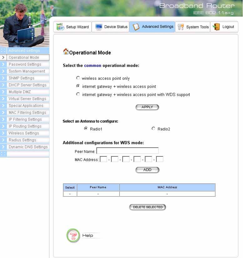
28 Chapter 4 Advanced Settings This section contains advanced setting procedures for the a+g Router. It describes modifications that normally you may not need for basic system operation. One exception is changing your password: it is highly recommended that you change the default factory setting as soon as you start to use your a+g Router. Operational Mode Before you start to use the device, you need to select the operational mode to be wireless AP only or both Internet gateway and wireless AP: Wireless Access Point only: When this is selected, the router operates in the AP-only Mode, and connects Wireless Client Users to the Ethernet (WAN). Internet Gateway + Wireless Access Point: When this is selected, the router will function as an Internet access sharing device as well as a wireless AP. Internet Gateway + Wireless Access Point with WDS Support: When this is selected, the router will function as an Internet access sharing device as well as a wireless AP, plus the mode to participate in the wireless distribution system. This could broaden the WLAN scope across several AP s. You should add all the WDS participants' MAC addresses with a mnemonic name in addition. When adding a WDS participant, you also have to select the radio (i.e. Radio1 or Radio2) that the participant will be connected with. 26
29 27

30 Password Settings Your a+g Router comes with a default factory password of password. After you start using the router, you should change the default password. To change the password, press the Password Settings button to enter the Password Settings screen, enter the current password followed by the new password twice. The entered characters will appear as asterisks. If you forgot the password, the only way to recover it is to return the device to its default state as shipped from the factory. To restore the password to the default password, please refer to the section, "What if I forgot the Password?" in the user manual. 28
31 System Management Clicking the System Management button allows system related parameters to be configured for the a+g Router. Remote Management: The remote management feature allows you to manage your a+g Router remotely through the use of an HTTP browser. The system allows you to (1) allow remote management from all WAN IP addresses, to (2) allow remote management from up to two WAN IP addresses, or to (3) disallow remote management from any WAN IP addresses. System Administration: The router allows you to designate special port numbers other than the standard 80 for http for remote management. It also allows you to specify the duration of idle time (inactivity) before a web browser session times out. The default time-out value is 10 minutes. UPnP: The router's Universal Plug and Play (UPnP) feature allows a Windows XP/ME PC to discover the router and automatically show an icon in the task bar on the screen. You can double-click the icon to access the router directly (without having to specify its IP address). Disable Ping: "Ping" is a utility for testing the connectivity. Response to a ping can be disabled, such as when you do not want the router to be accessed (e.g., attacked) from the Internet. Syslog: Syslog is an IETF (Internet Engineering Task Force - the Internet standards body)- conformant standard for logging system events (RFC-3164). When the a+g Router encounters an error or warning condition (e.g., a log-in attempt with an invalid password), it will create a log in the system log table. To be able to remotely view such system log events, you need to check the Enable Syslog box, configure the IP address of a PC where a Syslog daemon is running in the background. When doing so, the a+g Router will send logged events over the network to the PC for future viewing. Syslog server IP address: The IP address of the PC where the Syslog daemon is running. 29
32 30

33 SNMP Settings This screen allows you to configure SNMP parameters including the system name, the location and contact information. Additionally, you can configure the a+g Router to send SNMP Traps to remote SNMP management stations. Traps are unsolicited alert messages that a+g Router sends to remote management stations. System Name: A name that you assign to your a+g Router. It is an alphanumeric string of up to 30 characters. 31
34 System Location: Description of where your a+g Router is physically located. It is an alphanumeric string of up to 60 characters. System Contact: Contact information for the system administrator responsible for managing your a+g Router. It is an alphanumeric string of up to 60 characters. Community String For Read: If you intend the router to be managed from a remote SNMP management station, you need to configure a read-only community string for read-only operation. The community string is an alphanumeric string of up to 15 characters. Community String For Write: For read-write operation, you need to configure a write community string. A trap manager is a remote SNMP management station where special SNMP trap messages are generated (by the router) and sent to in the network. You can define trap managers in the system. You can add a trap manager by entering a name, an IP address, followed by pressing the ADD button. You can delete a trap manager by selecting the corresponding entry and press the DELETE SELECTED button. You enable a trap manager by checking the Enable box in the corresponding entry or disable the trap manager by un-checking the Enable box. 32

35 DHCP Server Settings The DHCP server option allows the a+g Router to assign IP addresses to DHCP client devices on your wired or wireless LAN to obtain IP addresses automatically. If you want the Router to act as a DHCP server and assign private IP addresses to requesting DHCP clients on the LAN, you need to check the Enable DHCP Server box. 33
36 You can select one of the following two ways to assign IP addresses: Assigns IP addresses to wired or wireless clients from the following range: When IP addresses are assigned to a requesting DHCP client, after the lease time, the client is expected to renew the lease. Its default value is minutes. The from and to range of IP addresses to be assigned to requesting DHCP clients can be configured manually, with the default being 2 to 254. After you enter the information, you should press APPLY. Assigns the following IP address to the client with the following MAC address: You can also specify the IP address to be assigned to a device with a pre-configured MAC address. You can add such a mapping by entering a MAC address, and the IP address to be assigned, followed by pressing the ADD button. Up to 20 mappings can be added. You can delete a mapping by selecting the corresponding entry and press the DELETE SELECTED button. DHCP Table: Press this button will cause the screen to jump to DHCP client table page. 34

37 Multiple DMZ The router supports multiple software DMZ ports, and they are implemented through software. When the router receives incoming data from the Internet, it will search through an internal address translation table to perform address translation function. If a match can be found, the data will be forwarded to the corresponding device in your local LAN, otherwise the data will be dropped or forwarded to the default DMZ if it is configured. An additional feature is to allow devices with WAN IP addresses to be used by the Internet users to access private devices in your local LAN. In this case, you need to configure the mapping between the WAN IP address and the private IP address. To add the default DMZ, you need to select Default DMZ and enter the local DMZ IP address, followed by pressing the ADD button. To add a device for multiple DMZ, first select Multiple DMZ, add a mnemonic name, a public WAN IP address, and the local DMZ IP address on the LAN, followed by pressing the ADD button. You can delete a DMZ entry by selecting the corresponding entry and press the DELETE SELECTED button. 35

38 Virtual Server Settings A Virtual Server is a server built on a single or a cluster of real servers. A DMZ server is a term commonly used to describe the default Virtual Server - the router will redirect all traffic from the Internet without a valid port address mapping to this device. An HTTP server with a private IP address on the LAN allows access from the Internet by mapping a special port to the HTTP server. In this case, the HTTP service will be mapped to a special port of the Router. You can add a virtual server mapping by (1) selecting the service name (such as HTTP, FTP, TELNET, SMTP, POP3, CUSTOM), (2) enter the public port number to be used (either a single port number or a range), (3) enter the local IP address of the server on your LAN, (4) enter its local port number to map to (either a single port number or the starting port number of a range), (5) followed by pressing the ADD button. You can delete a mapping by selecting the corresponding entry and press the DELETE SELECTED button. Note: Virtual Server Setting and IP Filtering may affect with each other. 36
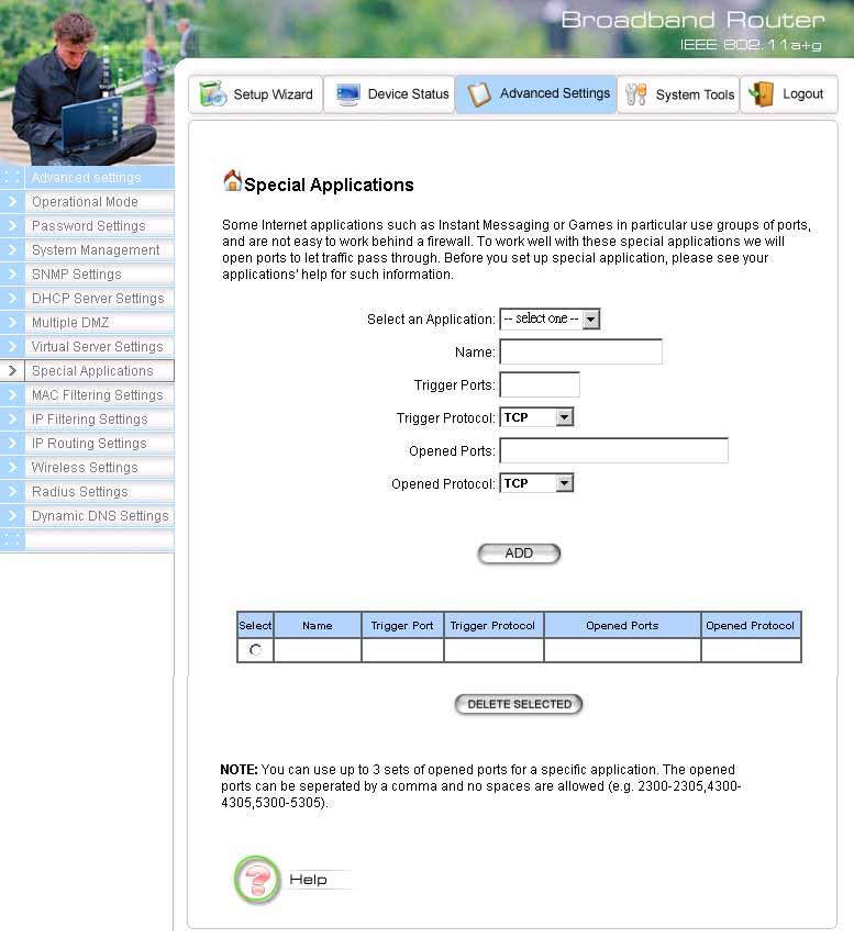
39 Special Applications Special applications such as some Internet games are getting to be increasingly popular. These applications usually work in the following manner: A client can start an Internet game by first registering with a game server on the Internet. Other clients can, using the corresponding protocol, join the game by checking with the server and deciding if to join the game. A client can "leave" the game at any time. If the initiating client is behind your router, you need to add the application by performing the following configuration: Select an application: Select an application that you want to add to the supported list. You should choose "Other" if your application is not explicitly shown in the list. Name: You can provide a mnemonic name. Trigger Port: You need to specify, based on instructions provided by your application s user manual, the (UDP/TCP) port number in the router that the initiating client uses to start an Internet game. Trigger Type: Select UDP, TCP, or both for the trigger port. Opened ports: You need to specify the port numbers in the router that joining clients can use to communicate with the initiating client, again based on instructions provided by your application user manual. Public Type: Select UDP, TCP, or both for the Opened ports. After you finish the above, you press the ADD button to add an entry to the table. You can delete an entry by selecting the corresponding entry and press the DELETE SELECTED button. 37
40 38

41 MAC Filtering Settings The a+g Router allows you to define a list of MAC addresses. One of three mutually exclusive rules can be selected to forward/filter data packets based on these MAC addresses. Disable MAC address control list: When this radio button is selected, no MAC address filtering will be performed. Enable GRANT address control list: When this radio button is selected, only packets received from the wireless LAN interface with the configured MAC addresses will be allowed/forwarded. Enable DENY address control list: When this radio button is selected, only packets received from the wireless LAN interface with the configured MAC addresses will be denied/filtered. Once a choice is made, the choice applies to all filtering rules. To add a filtering rule, configure the following: Mnemonic Name: the name to identify the filter MAC Address: the MAC address for grant or deny. After you finish the above, you press the ADD button to add the entry to the table. There are up to 32 MAC filtering rules could be configured. You can delete an entry by selecting the corresponding entry and press the DELETE SELECTED button. 39
42 IP Filtering Settings Three mutually exclusive rules can be defined to forward/filter IP packets based on their IP address and/or port numbers. Disable IP filtering: If this is selected, the IP filtering feature is disabled. No IP filtering will be performed. GRANT IP access: When this is elected, packets received from/transmitted to WAN with specified (source or destination) IP addresses will be allowed/forwarded. DENY IP access: Packets received from/transmitted to WAN with the specified IP addresses will be denied/filtered. Once a choice is made, the choice applies to all filtering rules. To define/add an IP filtering rule, enter the following information Name: The name of the filter IP Protocol: TCP or UDP Apply to: You need to select whether the filtering rule should apply to packets outbound for the Internet or inbound from the Internet. Source IP address: you can select Any, Single IP, or a Network (of source IP addresses). Source Port: you can select Any, Single, or a Range of port numbers. Destination IP address: Any, Single IP, or a Network (of destination IP addresses). Destination Port: you can select Any, Single, or a Range of port numbers. After you finish the above, you press the ADD button to add the entry to the table. There are up to 32 IP filtering rules could be configured. You can delete an entry by selecting the corresponding entry and press the DELETE SELECTED button. Please Note that IP filtering is a sophisticated feature that can severely impact your Router operation. Please be sure that you fully understand it before you use this feature. If you make any mistakes, it can produce dramatic and potentially undesirable results. 40
43 41
44 IP Routing Settings Dynamic Routing: enable gateway to exchange the routing table dynamically through LAN port. Currently you can choose to use RIPv1 or RIPv2 with Send enabled (active mode) or disabled (passive mode). Static Routing: If you have routers on your LAN or WAN, you can configure static routes on the a+g Router to route network traffic to a specific, predefined destination. The a+g Router routes packets based only on the packet's destination not on the source of a packet. Static Routes are configured when network traffic is directed to a specific destination on the network whether it is the LAN or WAN. For instance, you can configure the a+g Router to route traffic destined to a particular network to a specific router on the LAN or WAN using the following steps: 1. Enter the IP address of the destination network in the Destination Network field. 2. Enter the subnet in the Subnet Mask field. 3. Enter the IP address of the specific router in the Gateway IP Address field. 4. Select LAN or WAN, where is the specific router is, from the Interface menu. 6. Click Add. IP Routing Table: The Routing Table shows a list of destinations that the IP software maintains on each host and router. The destination network IP address, subnet mask, gateway address, and the corresponding interface are displayed. Note: The a+g Router can support up to 128 static route entries. 42
45 43

46 Wireless Settings You can use this screen to configure various parameters of your a+g Router. Beacon Interval: The a+g Router broadcasts beacon frames regularly to announce its existence. The beacon Interval specifies how often beacon frames are transmitted - in time unit of milliseconds. Its default value is 100; a valid value should be between 20 and RTS Threshold: RTS/CTS frames are used to gain control of the medium for transmission. Any unicast (data or control) frames larger than the specified RTS threshold must be transmitted following the RTS/CTS handshake exchange mechanism. The RTS threshold should have a value between 0 and 2347 bytes, with a default value of A value of zero activates the RTS/CTS handshake before every transmission. It is recommended that this value does not deviate from the default too much. Fragmentation: When the size of a unicast frame exceeds the fragmentation threshold, the frame will be fragmented before transmission. The threshold should have a value of bytes, with a default value of If you experience a high packet error rate, you should slightly decrease the Fragmentation Threshold. DTIM Interval: The a+g Router buffers packets for stations that operate in the power-saving mode. A Delivery Traffic Indication Message (DTIM) contains information on which powerconserving stations have packets waiting to be received. The DTIM interval specifies how often beacon frames should contain DTIMs. It should have a value between 1 and 255, with a default value of 3. 44
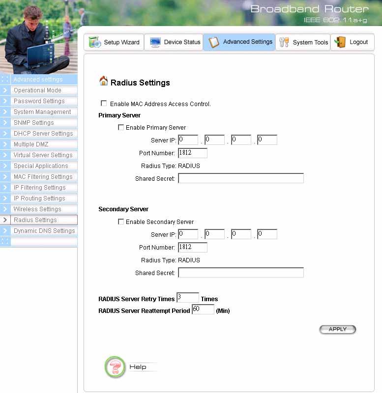
47 RADIUS Settings RADIUS (Remote Access Dial-In User Service) servers provide centralized authentication services to wireless clients. Up to two RADIUS servers can be defined, one acting as a primary, and the other as a backup. Enable Primary Server: To configure the primary server, check the Enable Primary Server box, and configure the following parameters: Server IP: The IP address of the RADIUS server Port Number: The port number your RADIUS server uses for authentication. The default setting is Shared Secret: This is used by your RADIUS server in the Shared Secret field in RADIUS protocol messages. The shared secret configured in the a+g Router must match the shared secret configured in the RADIUS server. The shared secret can contain up to 64 alphanumeric characters. Enable Secondary Server: To configure the secondary server, check the Enable Secondary Server box, and configure the same parameters as for the primary server. RADIUS Server Retry Times: The number of times the a+g Router should attempt to contact the primary server before giving up. RADIUS Server Reattempt Period: After failed to contact the primary RADIUS server, the a+g Router will re-attempt to contact the primary server every this mount of minutes. Enable MAC Address Access Control: MAC address filtering requires a MAC address filter table to be created in either the a+g Router and/or the RADIUS server. During the Authentication phase, the MAC address filter table is searched for a match against the wireless client s MAC address to determine whether the station is to be allowed or denied to access the network. To leverage a RADIUS server for MAC address access control, check the box here. 45
48 46
.")
49 Dynamic DNS Settings Some people advertise the IP addresses of their routers so that Internet users can access these routers (which is actually to access virtual servers behind these routers) using these IP addresses. However, for those routers that are assigned dynamic IP addresses from the ISP, this approach requires additional work (since the addresses assigned are not always the same). The a+g Router implements the dynamic DNS feature so that each time it is booted, it will re-register its domain-name-to-ip-address mapping with the dynamic DNS server you use (currently only DynDNS.org is supported), the service provider that provides domain name to IP address mapping. This is so that you can advertise your router by providing your domain name, while Internet users can access the router using the domain name, not the router s IP address. To activate this feature, you need to check the Enable Dynamic DNS Client using DynDNS.org box first, and then configure the following parameters: Hostname: the hostname (domain name) registered with DynDNS.org by you. Username: the username required to log in to the domain name server maintained by DynDNS.org. Password: the password required to log in to the domain name server maintained by DynDNS.org. 47

50 Managing your a+g Router This Chapter covers other management aspects of your a+g Router: Chapter 5 How to view the device status How to view the system log How to upgrade your a+g Router firmware How to save or restore configuration changes How to reboot your a+g Router What if you forgot the password How to View the device Status You can monitor the system status and get general device information from the Device Information screen: 48

51 How to View the System Log The a+g Router maintains a system log that you can use to track events that have occurred in the system. Such event messages can sometimes be helpful in determining the cause of a problem that you may have encountered. You can select System Log on the left to view log events recorded in the system. The System Log entries are shown in the main screen along with the log level, the severity level of messages that are being displayed (a low number such as 2 means critical), and the uptime, the amount of time since the a+g Router was last reset. The maximum number of entries is 128. If there are more than 128 entries, older entries will be deleted. 49

52 DHCP Client Table The DHCP client table lists current DHCP clients connected with its host name, IP address, MAC address, expiration time, and entry type. 50
53 Wireless Client Table The wireless client table lists the current wireless clients with the radio it is associated with, its MAC address, state, transmitted packets, and received packets. 51
54 Bridge Table The bridge table shows all MAC entries learned from the wired LAN interface, wireless clients, and WDS peers. 52

55 Radio Table The radio table shows the information of each radio, including the current mode, channel, number of clients associated, number of packets transmitted and received, and number of errors happened. 53

56 Upgrading Firmware You can upgrade your a+g Router s firmware (the software that controls your a+g Router s operation). Normally, this is done when a new version of firmware offers new features that you want, or solves problems you have encountered when using the current version. System upgrade can be performed through the System Upgrade option as follows: Step 1 Select System Tools, then Firmware Upgrade from the menu and the following screen displays: Step 2: To update the a+g Router firmware, first download the firmware from the distributor s web site to your local disk. Then from the above screen enter the path and filename of the firmware (or click Browse to select the path and filename of the firmware). Next, Click the Upgrade button. The new firmware will begin loading to your a+g Router. After a message appears telling you that the operation is complete, you need to reset the system to have the new firmware take effect. Note: It is recommended that you do not upgrade your a+g Router if you are happy with its operation. 54

57 How to Save or Restore Configuration Changes You can save system configuration settings to a file, and later download it back to the a+g Router system by following the steps below. Step 1 Select Configuration Save and Restore from the System Tools menu and the following screen displays: Step 2 Click SAVE TO FILE and then select a local file to save to, or click RESTORE FROM FILE and then select a local file to upload. 55

58 How to Restore the System Settings to the Factory Defaults You can restore the system settings to the factory defaults. Step 1 Select Factory Default from the System Tools menu and the following screen displays: Step 2 Click YES to restore the system configurations to the factory defaults, and the system will reboot automatically. 56
WLA-5000AP Access Point Mode
 WLA-5000AP Access Point Mode User s Guide Copyright Statement No part of this publication may be reproduced, stored in a retrieval system, or transmitted in any form or by any means, whether electronic,
MIMO Wireless Broadband Route r User s Manual 1
 MIMO Wireless Broadband Router User s Manual 1 Introduction...4 Features...4 Minimum Requirements...4 Package Content...4 Note...4 Get to know the Broadband Router...5 Back Panel...5 Front Panel...6 Setup
Wireless Broadband Router
 LW6005A-R2 Wireless Broadband Router Manual 1 Introduction... 4 Features... 4 Minimum Requirements... 4 Package Content... 4 Note... 4 Get to know the Broadband Router... 5 Back Panel... 5 Front Panel...
Wireless-G Router User s Guide
 Wireless-G Router User s Guide 1 Table of Contents Chapter 1: Introduction Installing Your Router System Requirements Installation Instructions Chapter 2: Preparing Your Network Preparing Your Network
Broadband Router. User s Manual
 Broadband Router User s Manual 1 Introduction... 4 Features... 4 Minimum Requirements... 4 Package Content... 4 Note... 4 Get to know the Broadband Router... 5 Back Panel... 5 Front Panel... 6 Setup Diagram...7
RX3041. User's Manual
 RX3041 User's Manual Table of Contents 1 Introduction... 2 1.1 Features and Benefits... 3 1.2 Package Contents... 3 1.3 Finding Your Way Around... 4 1.4 System Requirements... 6 1.5 Installation Instruction...
Introduction... 3 Features... 3 Minimum Requirements... 3 Package Content... 3 Note... 3 Get to know the Broadband Router... 4 Back Panel...
 Introduction... 3 Features... 3 Minimum Requirements... 3 Package Content... 3 Note... 3 Get to know the Broadband Router... 4 Back Panel... 4 Front Panel... 5 Setup Diagram... 6 Getting started... 7 Chapter
WL5041 Router User Manual
 TECOM WL5041 Router User Manual TECOM CO., LTD. March 2003 2003 by TECOM CO., LTD. All rights reserved. Printed in Taiwan Table of contents Package Contents--------------------------------------- 2 Installing
CWA-854HT 54 Mbps Wireless-G High Transmission Access Point User s Guide
 CWA-854HT 54 Mbps Wireless-G High Transmission Access Point User s Guide May 2006 Version 1.00 1 Table of Contents Table of Contents... 2 List of Figures... 4 List of Tables... 6 Chapter 1. Introduction...
WH-9200AP a/b/g Dual Radio Wireless Base Station. User s Manual
 WH-9200AP 802.11a/b/g Dual Radio Wireless Base Station User s Manual Regulatory Information Federal Communication Commission Interference Statement This equipment has been tested and found to comply with
IP806GA/GB Wireless ADSL Router
 IP806GA/GB Wireless ADSL Router 802.11g/802.11b Wireless Access Point ADSL Modem NAT Router 4-Port Switching Hub User's Guide Table of Contents CHAPTER 1 INTRODUCTION... 1 Wireless ADSL Router Features...
Linksys E2000 Advanced Wireless-N Router. User Guide
 User Guide Table of Contents Contents Chapter 1: Product Overview 1 Top....................................................... 1 Back...................................................... 1 Horizontal
DSL/CABLE ROUTER with PRINT SERVER
 USER S MANUAL DSL/CABLE ROUTER with PRINT SERVER MODEL No:SP888BP http://www.micronet.info 1 Content Table CHAPTER 0:INTRODUCTION... 4 FEATURES... 4 MINIMUM REQUIREMENTS... 4 PACKAGE CONTENT... 4 GET TO
Introduction... 3 Features... 3 Minimum Requirements... 3 Package Content... 3 Get to know the Broadband Router... 4 Back Panel... 4 Front Panel...
 Introduction... 3 Features... 3 Minimum Requirements... 3 Package Content... 3 Get to know the Broadband Router... 4 Back Panel... 4 Front Panel... 5 Setup Diagram... 6 Getting started... 7 Chapter 1...
LevelOne FBR-1405TX. User s Manual. 1 PORT BROADBAND ROUTER W/4 LAN Port. Version: 1.0
 LevelOne FBR-1405TX 1 PORT BROADBAND ROUTER W/4 LAN Port User s Manual Version: 1.0 Introduction... 3 Features... 3 Minimum Requirements... 3 Package Content... 3 Get to know the Broadband Router... 4
Security SSID Selection: Broadcast SSID:
 69 Security SSID Selection: Broadcast SSID: WMM: Encryption: Select the SSID that the security settings will apply to. If Disabled, then the device will not be broadcasting the SSID. Therefore it will
AirCruiser G Wireless Router GN-BR01G
 AirCruiser G Wireless Router GN-BR01G User s Guide i Contents Chapter 1 Introduction... 1 Overview...1 Features...1 Package Contents...2 AirCruiser G Wireless Router Rear Panel...2 AirCruiser G Wireless
User Manual DIR-615. Wireless Router with Built-in 4-port Switch
 DIR-615 Wireless Router with Built-in 4-port Switch December 2011 Contents Chapter 1. Introduction...4 Contents and Audience...4 Conventions...4 Document Structure...4 Chapter 2. Overview...5 General Information...5
Multi-Homing Broadband Router. User Manual
 Multi-Homing Broadband Router User Manual 1 Introduction... 4 Features... 4 Minimum Requirements... 4 Package Content... 4 Note... 4 Get to know the Broadband Router... 5 Back Panel... 5 Front Panel...
802.11N Wireless Broadband Router
 802.11N Wireless Broadband Router Pre-N Wireless Access Point Broadband Internet Access WPS 4-Port Switching Hub User's Guide Table of Contents CHAPTER 1 INTRODUCTION... 1 Wireless Router Features... 1
Wireless b/g/n 150Mbps AP Router
 Wireless 802.11b/g/n 150Mbps AP Router User Manual V1.2 2009-11-30 Package Contents The following items should be found in your package: One Wireless 802.11b/g/n 150Mbps Broadband Router One DC 9v power
802.11a g Dual Band Wireless Access Point. User s Manual
 802.11a+802.11g Dual Band Wireless Access Point User s Manual 0 Chapter 1 Introduction 1.1 Feature Fully interoperable with IEEE 802.11b compliant products. High-Speed data transfer rate up to 11Mbps.
EnGenius Quick Start Guide
 T he operates seamlessly in the 2.4 GHz frequency spectrum supporting the 802.11b (2.4GHz, 11Mbps) and the newer, faster 802.11g (2.4GHz, 54Mbpswireless standard. High output power and high sensitivity
LevelOne WBR User s Manual. 11g Wireless ADSL VPN Router. Ver
 LevelOne WBR-3407 11g Wireless ADSL VPN Router User s Manual Ver 1.00-0510 Table of Contents CHAPTER 1 INTRODUCTION... 1 Wireless ADSL Router Features... 1 Package Contents... 5 Physical Details... 6 CHAPTER
CHAPTER 7 ADVANCED ADMINISTRATION PC
 ii Table of Contents CHAPTER 1 INTRODUCTION... 1 Broadband ADSL Router Features... 1 Package Contents... 3 Physical Details... 4 CHAPTER 2 INSTALLATION... 6 Requirements... 6 Procedure... 6 CHAPTER 3 SETUP...
Introduction... 3 Features... 3 Minimum Requirements... 3 Package Content... 3 Get to know the Broadband Router... 4 Back Panel... 4 Front Panel...
 Introduction... 3 Features... 3 Minimum Requirements... 3 Package Content... 3 Get to know the Broadband Router... 4 Back Panel... 4 Front Panel... 5 Setup Diagram... 6 Getting started... 7 Chapter 1...
Wireless LAN Device Series CPE2615. User Manual. v
 Wireless LAN Device Series CPE2615 User Manual v20080312 Preface To use this guide, you should have experience working with the TCP/IP configuration and be familiar with the concepts and terminology of
Wireless LAN Device Series CPE2615. User Manual. v
 Wireless LAN Device Series CPE2615 User Manual v20081230 Preface To use this guide, you should have experience working with the TCP/IP configuration and be familiar with the concepts and terminology of
VG422R. User s Manual. Rev , 5
 VG422R User s Manual Rev 1.0 2003, 5 CONGRATULATIONS ON YOUR PURCHASE OF VG422R... 1 THIS PACKAGE CONTAINS... 1 CONFIRM THAT YOU MEET INSTALLATION REQUIREMENTS... 1 1. INSTALLATION GUIDE... 2 1.1. HARDWARE
LevelOne FBR-1405TX. User s Manual. 1-PORT BROADBAND ROUTER W/4 LAN Port
 LevelOne FBR-1405TX 1-PORT BROADBAND ROUTER W/4 LAN Port User s Manual 1 Introduction... 4 Features... 4 Minimum Requirements...4 Package Content... 4 Note...4 Get to know the Broadband Router... 5 Back
DC-228. ADSL2+ Modem/Router. User Manual. -Annex A- Version: 1.0
 DC-228 ADSL2+ Modem/Router -Annex A- User Manual Version: 1.0 TABLE OF CONTENTS 1 PACKAGE CONTENTS...3 2 PRODUCT LAYOUT...4 3 NETWORK + SYSTEM REQUIREMENTS...6 4 DC-228 PLACEMENT...6 5 SETUP LAN, WAN...7
TCP/IP CONFIGURATION 3-6
 TCP/IP CONFIGURATION 3. Type IPCONFIG /RENEW and press the Enter key. Verify that your IP Address is now 192.168.2.xxx, your Subnet Mask is 255.255.255.0 and your Default Gateway is 192.168.2.1. These
Broadband Router DC-202. User's Guide
 Broadband Router DC-202 User's Guide Table of Contents CHAPTER 1 INTRODUCTION... 1 Broadband Router Features... 1 Package Contents... 3 Physical Details...3 CHAPTER 2 INSTALLATION... 5 Requirements...
Gigaset Router / en / A31008-E105-B / cover_front_router.fm / s Be inspired
 s Be inspired Table of Contents Table of Contents Safety precautions........................... 3 The Gigaset Router........................... 3 Features and Benefits..................................................
NBG-416N. Wireless N-lite Home Router. Default Login Details. IMPORTANT! READ CAREFULLY BEFORE USE.
 NBG-416N Wireless N-lite Home Router IMPORTANT! Default Login Details LAN IP https://192.168.1.1 Address User Name admin Password 1234 READ CAREFULLY BEFORE USE. KEEP THIS GUIDE FOR FUTURE REFERENCE. IMPORTANT!
AplombTech Smart Router Manual
 AplombTech Smart Router Manual (Version: 1.0) 1 Version & Purpose Version Manual version V 1.0 Explanation Corresponds to the initial version of device Purpose This manual describes the function features
Prestige 660HW Series. Prestige 660H Series. Quick Start Guide
 Prestige 660HW Series ADSL 2+ 4-Port Gateway with 802.11g Wireless Prestige 660H Series ADSL 2+ 4-Port Gateway Quick Start Guide Version 3.40 01/2005 Table of Contents Introducing the Prestige... 3 1 Hardware
300M Wireless-N Broadband Router User Manual
 300M Wireless-N Broadband Router Model No.: ib-wrb314n User Manual Ver.: 1.0.0 Contents...Error! Bookmark not defined. Chapter 1 Product Overview... 3 Package Contents 3 Conventions....4 Panel Overview...
Wireless LAN Access Point
 Wireless LAN Access Point IEEE 802.11b 11Mbps User s Manual Table of Contents Chapter 1 Introduction... 1 1.1 Package Contents... 2 1.2 Features... 2 1.3 Specifications... 2 1.4 Physical Description...
Section 3 - Configuration. Enable Auto Channel Scan:
 Enable Auto Channel Scan: Wireless Channel: The Auto Channel Scan setting can be selected to allow the DGL-4500 to choose the channel with the least amount of interference. Indicates the channel setting
802.11g Wireless High-power Broadband Router with passive PoE. User s Manual
 802.11g Wireless High-power Broadband Router with passive PoE User s Manual Table of Contents CHAPTER 1: INTRODUCTION... 2 WIRELESS ROUTER FEATURES... 2 PACKAGE CONTENTS... 4 PHYSICAL DETAILS... 5 ABOUT
User Manual. OT-1044ns
 User Manual OT-1044ns CONTENTS Chapter 1 Introduction... 3 1.1 Features... 3 1.2 Environments... 3 1.3 System Requirement... 4 Chapter 2 Hardware Installation... 4 2.1 Led indicators... 4 2.2 Back Panel
4-Port Broadband user manual Model
 4-Port Broadband Router user manual Model 524537 INT-524537-UM-0309-02 introduction Thank you for purchasing the INTELLINET NETWORK SOLUTIONS 4-Port Broadband Router, Model 524537. Combining a router,
A Division of Cisco Systems, Inc. GHz g. Wireless-G. User Guide. Broadband Router with 2 Phone Ports WIRELESS WRT54GP2A-AT. Model No.
 A Division of Cisco Systems, Inc. GHz 2.4 802.11g WIRELESS Wireless-G Broadband Router with 2 Phone Ports User Guide Model No. WRT54GP2A-AT Copyright and Trademarks Specifications are subject to change
Internet Broadband Router
 Internet Broadband Router XRT-401D/402D/104D User s Manual 1 Copyright Copyright (C) 2004 PLANET Technology Corp. All rights reserved. The products and programs described in this User s Manual are licensed
GHz 2, g. Wireless-G. User Guide. ADSL Home Gateway WIRELESS WAG200G (EU) Model No.
 Model No.") GHz 2,4 802.11g WIRELESS Wireless-G ADSL Home Gateway User Guide Model No. WAG200G (EU) Copyright and Trademarks Specifications are subject to change without notice. Linksys is a registered trademark or
GHz 2,4 802.11g WIRELESS Wireless-G ADSL Home Gateway User Guide Model No. WAG200G (EU) Copyright and Trademarks Specifications are subject to change without notice. Linksys is a registered trademark or
Broadband Router. with 2 Phone Ports WIRED. Installation and Troubleshooting Guide RT31P2. A Division of Cisco Systems, Inc. Model No.
 A Division of Cisco Systems, Inc. Broadband Router with 2 Phone Ports WIRED Installation and Troubleshooting Guide Model No. RT31P2 Copyright and Trademarks Specifications are subject to change without
Introduction... 3 Features... 3 Minimum Requirements... 3 Package Content... 3 Get to know the Broadband Router... 4 Back Panel... 4 Front Panel...
 Introduction... 3 Features... 3 Minimum Requirements... 3 Package Content... 3 Get to know the Broadband Router... 4 Back Panel... 4 Front Panel... 5 Setup Diagram... 6 Getting started... 7 Chapter 1...
802.11N Wireless ADSL Router
 802.11N Wireless ADSL Router Pre-N Wireless Access Point ADSL Modem NAT Router WPS 4-Port Switching Hub User's Guide Table of Contents CHAPTER 1 INTRODUCTION...1 Wireless ADSL Router Features...1 Package
LevelOne FBR User s Manual. 1W, 4L 10/100 Mbps ADSL Router. Ver
 LevelOne FBR-1416 1W, 4L 10/100 Mbps ADSL Router User s Manual Ver 1.00-0510 Table of Contents CHAPTER 1 INTRODUCTION... 1 FBR-1416 Features... 1 Package Contents... 3 Physical Details... 3 CHAPTER 2
XG-520 Wireless b/g Portable Router. User s Manual
 XG-520 Wireless 802.11b/g Portable Router User s Manual FCC Certifications This equipment has been tested and found to comply with the limits for a Class B digital device, pursuant to Part 15 of the FCC
Wireless LAN Device Series. DLB2300-A User Manual
 Wireless LAN Device Series WLAN Outdoor Bridge DLB2300-A User Manual Version. 1.2.1 (25.03.2005) Table of Contents Preface...3 Ch 1. DLB2300A Installation...4 Packing List...4 Ch 2. First Time Configuration...5
Multi-Function Wireless A/P Router User s Guide
 Multi-Function Wireless A/P Router User s Guide Model CNWR-811P Wireless Access Point Router W / Printer Sharing TABLE OF CONTENTS CHAPTER 1 INTRODUCTION...1 CNWR-811P Features...1 Package Contents...3
Wireless g AP. User s Manual
 Wireless 802.11g AP User s Manual Version 1.8 User s Guide 0 Copyright Statement No part of this publication may be reproduced, stored in a retrieval system, or transmitted in any form or by any means,
LKR Port Broadband Router. User's Manual. Revision C
 LKR-604 4-Port Broadband Router User's Manual Revision C 1 Contents 1 Introduction... 4 1.1 Features... 4 1.2 Package Contents... 4 1.3 Finding Your Way Around... 5 1.3.1 Front Panel... 5 1.3.2 Rear Panel
LevelOne. User Manual. WAP Mbps PoE Wireless AP V3.0.0
 LevelOne WAP-0005 108Mbps PoE Wireless AP User Manual V3.0.0 i TABLE OF CONTENTS CHAPTER 1 INTRODUCTION... 1 FIGURE 1: WIRELESS ACCESS POINT... 1 FEATURES OF YOUR WIRELESS ACCESS POINT... 1 Security Features...
A Division of Cisco Systems, Inc. Wireless-G. Travel Router with SpeedBooster. User Guide WIRELESS WTR54GS. Model No.
 A Division of Cisco Systems, Inc. WIRELESS Wireless-G Travel Router with SpeedBooster User Guide Model No. WTR54GS Copyright and Trademarks Specifications are subject to change without notice. Linksys
A5500 Configuration Guide
 A5500 Configuration Guide Sri Ram Kishore February 2012 Table of contents Gateway Configuration... 3 Accessing your gateway configuration tool... 3 Configuring your broadband Internet access... 3 Configuring
A Division of Cisco Systems, Inc. Broadband Router. with 2 Phone Ports. User Guide WIRED RT41P2-AT. Model No.
 A Division of Cisco Systems, Inc. WIRED Broadband Router with 2 Phone Ports User Guide Model No. RT41P2-AT Copyright and Trademarks Specifications are subject to change without notice. Linksys is a registered
Table of Contents. Chapter 1Introduction Package Contents Features Specifications Physical Description...
 Table of Contents Chapter 1Introduction... 3 1.1 Package Contents... 3 1.2 Features... 3 1.3 Specifications... 3 1.4 Physical Description... 4 Chapter 2Wireless LAN Access Point Connection... 5 Chapter
IP819VGA g ADSL VoIP Gateway
 IP819VGA 802.11g ADSL VoIP Gateway 802.11g/802.11b Access Point ADSL Modem NAT Router VoIP Gateway User's Guide Table of Contents CHAPTER 1 INTRODUCTION... 1 802.11g ADSL VoIP Gateway Features... 1 Package
Internet Broadband Router
 Internet Broadband Router XRT-401D User s Manual 1 Copyright Copyright (C) 2003 PLANET Technology Corp. All rights reserved. The products and programs described in this User s Manual are licensed products
SOHOSpeed ADSL Ethernet/Wireless Gateway User s Manual
 SOHOSpeed ADSL Ethernet/Wireless Gateway User s Manual Revision 1.0 July 2004 SOHOSpeed ADSL Ethernet/Wireless Gateway User s Manual Table of Contents 1. INTRODUCTION...4 1.1 FEATURES...4 2. GATEWAY OVERVIEW...5
TEW-211BRP. Wireless AP Router. User s Manual
 TEW-211BRP Wireless AP Router User s Manual Version 1.4 - Jan 2002 CONTENTS Introduction...3 Hardware Installation...5 General Wireless AP Router System Connection...6 Wireless AP Router Default Settings
GHz 2, g. Home Wireless-G. Gateway WIRELESS. User Guide HG200. Model No. Downloaded from manuals search engine
 GHz 2,4 802.11g WIRELESS Home Wireless-G Gateway User Guide Model No. HG200 Copyright and Trademarks Specifications are subject to change without notice. Linksys is a registered trademark or trademark
Broadband Router User s Manual. Broadband Router User s Manual
 Broadband Router User s Manual Table of Contents 1 Introduction... 1 1.1 Features... 1 1.2 Package Contents... 2 1.3 LEDs & Connectors of Broadband Router... 2 1.4 System Requirements... 2 1.5 Installation
Conceptronic C100BRS4H Quick Installation Guide. Congratulations on the purchase of your Conceptronic 4-ports Broadband Router.
 Conceptronic C100BRS4H Quick Installation Guide Congratulations on the purchase of your Conceptronic 4-ports Broadband Router. The enclosed Hardware Installation Guide gives you a step-by-step explanation
WISNETWORKS. WisOS 11ac V /3/21. Software version WisOS 11ac
 WISNETWORKS User Manual V1.1 2016/3/21 Software version 1.0.0021 Table of contents 1. Setup& WMI... 3 1.1 Hardware Setup... 3 1.2 Web Management Interface... 3 2. Status... 4 2.1 Overview... 4 2.1.1 System...
TABLE OF CONTENT 1. ABOUT THIS GUIDE Overview of the User s Guide INTRODUCTION Overview Features...
 TABLE OF CONTENT 1. ABOUT THIS GUIDE... 3 1.1 Overview of the User s Guide... 3 2. INTRODUCTION... 3 2.1 Overview... 3 2.2 Features... 3 2.3 Panel Layout... 4 2.3.1 Front Panel... 4 2.3.2 Rear Panel...
Copyright and Trademarks. How to Use This User Guide
 Copyright and Trademarks Specifications are subject to change without notice. Linksys is a registered trademark or trademark of Cisco Systems, Inc. and/or its affiliates in the U.S. and certain other countries.
CE APPROVED.4 INTRODUCTION.5 PACKAGE CONTENTS. 6 PRE - INSTALLATION CHECKLIST. 6 SYSTEM REQUIREMENTS. 6 FEATURES AND BENEFITS.11 SETUP WIZARD.
 Web Edition Dec. 2002 Contents CE APPROVED...4 INTRODUCTION...5 PACKAGE CONTENTS... 6 PRE - INSTALLATION CHECKLIST... 6 SYSTEM REQUIREMENTS... 6 FEATURES AND BENEFITS... 7 4 - PORT CABLE/XDSL ROUTER...9
NBG-418N. Wireless N Home Router. Default Login Details. IMPORTANT! READ CAREFULLY BEFORE USE. KEEP THIS GUIDE FOR FUTURE REFERENCE.
 NBG-418N Wireless N Home Router IMPORTANT! Default Login Details LAN IP http://192.168.1.1 Address User Name admin Password 1234 READ CAREFULLY BEFORE USE. KEEP THIS GUIDE FOR FUTURE REFERENCE. IMPORTANT!
MW155R 150Mbps Wireless N Router
 150Mbps Wireless N Router REV1.0.0 1910080030 COPYRIGHT & TRADEMARK Specifications are subject to change without notice. is a registered trademark of MERCUSYS TECHNOLOGIES CO., LTD. Other brands and product
BOSSW221. User Manual
 BOSSW221 High Power Wireless Solution designed for Wireless ISP Service, Hot-Spot, and Backbone Max 400 mw with PoE & Radio 802.11b/g AP Client, AP Bridge, PtP Bridge, and WDS User Manual Congratulation
Wireless a CPE User Manual
 NOTICE Changes or modifications to the equipment, which are not approved by the party responsible for compliance, could affect the user's authority to operate the equipment. Company has an on-going policy
Oct 2007 Version 1.01
 Oct 2007 Version 1.01 Table of Contents Introduction...4 System Requirement...4 Getting Started...4 Installing the Smart WLAN Manager...5 Discovering the Switch and AP...9 Understanding the Screen Layout...12
DRG600-WIFI USER GUIDE
 DRG600-WIFI USER GUIDE P/N: DFB601CW Copyright 2008. All Rights Reserved. Printed May 15, 2008 All trademarks and trade names are the properties of their respective owners. Page 2 of 104 Contents INTRODUCTION...
Broadband Router DC 202
 Broadband Router DC 202 Full Manual Table of Contents DC-202 xdsl/cable Broadband router REQUIREMENTS...4 INTRODUCTION...4 DC-202 Features...4 Internet Access Features...4 Advanced Internet Functions...5
KW5590 Wireless Router User Manual
 KW5590 Wireless Router NOTICE This document contains proprietary information protected by copyright, and this Manual and all the accompanying hardware, software, and documentation are copyrighted. All
User Manual DIR-615. Wireless N 300 Home Router
 DIR-615 Wireless N 300 Home Router April 2013 Contents Chapter 1. Introduction...5 Contents and Audience...5 Conventions...5 Document Structure...5 Chapter 2. Overview...6 General Information...6 Specifications...7
User Manual. Rev:
 Default Login Details Login Address: www.mykasda.com Login Password: Set up by users Default Wi-Fi SSID: Kasda xxxx KW6516 (Printed on product label) Default Wi-Fi Password: 12345678 www.kasdanet.com Rev:
LP-2396K Outdoor 2.4GHz Wireless AP/CPE/Bridge
 User Manual LP-2396K Outdoor 2.4GHz Wireless AP/CPE/Bridge 1 Table of Contents 1. Introduction... 3 1.1 Product Introduction... 4 1.2 Package Content... 5 1.3 Product Features... 6 1.4 Application... 6
UIP1869V User Interface Guide
 UIP1869V User Interface Guide (Firmware version 0.1.8 and later) Table of Contents Opening the UIP1869V's Configuration Utility... 3 Connecting to Your Broadband Modem... 5 Setting up with DHCP... 5 Updating
User Guide AC750 Wireless Dual Band Router Archer C20(EU)4.0
4.0") User Guide AC750 Wireless Dual Band Router Archer C20(EU)4.0 REV4.0.0 1910012038 Contents About This Guide...1 Chapter 1. Get to Know About Your Router...........................2 1. 1. Product Overview............................................................
User Guide AC750 Wireless Dual Band Router Archer C20(EU)4.0 REV4.0.0 1910012038 Contents About This Guide...1 Chapter 1. Get to Know About Your Router...........................2 1. 1. Product Overview............................................................
Chapter 1 Introduction
 Copyright Statement is the registered trademark of Zonet Technology Inc. All the products and product names mentioned herein are the trademarks or registered trademarks of their respective holders. Copyright
Wireless-N Broadband AP / Router. User s Manual. Version 1.3
 Wireless-N Broadband AP / Router User s Manual Version 1.3 Federal Communication Commission Interference Statement This equipment has been tested and found to comply with the limits for a Class B digital
54Mbps Pocket Wireless Access Point (WL-330g)
") 54Mbps Pocket Wireless Access Point (WL-330g) Copyright 2004 ASUSTeK COMPUTER INC. All Rights Reserved. Contents Conventions... 2 Welcome!... 3 Package contents... 3 System requirements... 3 Device installation...
54Mbps Pocket Wireless Access Point (WL-330g) Copyright 2004 ASUSTeK COMPUTER INC. All Rights Reserved. Contents Conventions... 2 Welcome!... 3 Package contents... 3 System requirements... 3 Device installation...
SOHO 6 Wireless Installation Procedure Windows XP with Internet Explorer 5.x & 6.0
 SOHO 6 Wireless Installation Procedure Windows XP with Internet Explorer 5.x & 6.0 Before you Begin Before you install the SOHO 6 Wireless, you must have: A computer with a 10/100BaseT Ethernet card installed
The Administration Tab - Diagnostics
 The Administration Tab - Diagnostics The diagnostic tests (Ping and Traceroute) allow you to check the connections of your network components. Ping Test. The Ping test will check the status of a connection.
User s Manual. 11N Wireless LAN Broadband Router. Model No.: SP916GN.
 User s Manual 11N Wireless LAN Broadband Router Model No.: SP916GN http://www.micronet.info Table of Contents Chapter 1 Introduction... 1 1.1 Package Contents... 1 1.2 Key Features... 1 1.3 Safety Information...
Wireless Access Point
 802.11g / 802.11b / WPA Wireless Access Point User's Guide TABLE OF CONTENTS CHAPTER 1 INTRODUCTION... 1 Features of your Wireless Access Point... 1 Package Contents... 4 Physical Details... 4 CHAPTER
Wireless LAN Access Point
 Wireless LAN Access Point IEEE 802.11b/g 54Mbps 501903 User s Manual Table of Contents Chapter 1 Introduction... 1 1.1 Package Contents... 2 1.2 Features... 2 1.3 Specifications... 2 1.4 Physical Description...
Multi-Function Wireless Router. User's Guide. Wireless Access Point Broadband Internet Access. 4-Port Switching Hub
 Multi-Function Wireless Router Wireless Access Point Broadband Internet Access 4-Port Switching Hub User's Guide Table of Contents CHAPTER 1 INTRODUCTION... 1 Wireless Router Features... 1 Package Contents...
WL-601. Wireless Broadband modem/router. User Manual (ADSL2+, B/G) Version: 2.0
 Version: 2.0") WL-601 Wireless Broadband modem/router (ADSL2+, 802.11B/G) User Manual Version: 2.0 TABLE OF CONTENTS 1 KEY FEATURES...4 2 PACKAGE CONTENTS...5 3 PRODUCT LAYOUT...6 4 NETWORK + SYSTEM REQUIREMENTS...8
WL-601 Wireless Broadband modem/router (ADSL2+, 802.11B/G) User Manual Version: 2.0 TABLE OF CONTENTS 1 KEY FEATURES...4 2 PACKAGE CONTENTS...5 3 PRODUCT LAYOUT...6 4 NETWORK + SYSTEM REQUIREMENTS...8
WL-615. Wireless Broadband modem/router 54g. User Manual (ADSL2+, B/G) Version: 1.0
 Version: 1.0") WL-615 Wireless Broadband modem/router 54g (ADSL2+, 802.11B/G) User Manual Version: 1.0 TABLE OF CONTENTS...1...1 1KEY FEATURES...4 2PACKAGE CONTENTS...5 3PRODUCT LAYOUT...6 4NETWORK + SYSTEM REQUIREMENTS...8
WL-615 Wireless Broadband modem/router 54g (ADSL2+, 802.11B/G) User Manual Version: 1.0 TABLE OF CONTENTS...1...1 1KEY FEATURES...4 2PACKAGE CONTENTS...5 3PRODUCT LAYOUT...6 4NETWORK + SYSTEM REQUIREMENTS...8
A or G Wireless Router
 A or G Wireless Router 802.11a/802.11g/802.11b Wireless Access Point Broadband Internet Access 4-Port Switching Hub User's Guide DECLARATION OF CONFORMITY Per FCC Part 2 Section 2.1077(a) Responsible Party
Wireless USB Port Multi-Functional Printer Server. Model # AMPS240W. User s Manual. Ver. 1A
 Wireless USB 2.0 1-Port Multi-Functional Printer Server Model # AMPS240W User s Manual Ver. 1A Table of Contents 1 Introduction...3 1.1 Package Contents... 3 1.2 System Requirements... 3 2 Multi-Functional
Wireless-N Broadband Router
 USER GUIDE Model: WRT160N About This Guide About This Guide Icon Descriptions While reading through the User Guide you may see various icons that call attention to specific items. Below is a description
TABLE OF CONTENT 1. ABOUT THIS GUIDE Navigation of the User s Guide PRODUCT OVERVIEW Introduction Features...
 TABLE OF CONTENT 1. ABOUT THIS GUIDE... 3 1.1 Navigation of the User s Guide... 3 2. PRODUCT OVERVIEW... 3 2.1 Introduction... 3 2.2 Features... 3 2.3 Panel Layout... 4 2.3.1 Front Panel... 4 2.3.2 Rear