Session 5 The e v e o v l o ve v d P a P c a k c e k t e t Co C r o e r (EP E C P ) C : T he a l a l-ip based
|
|
|
- Irma Fields
- 6 years ago
- Views:
Transcription
: The all-ip based Core Network")

 Sami TABBANE 9-11 December 2013")
1 Session 5 The evolved Packet Core (EPC): The all-ip based Core Network of LTE ITU ASP COE Training on Technology, Standardization and Deployment of Long Term Evolution (IMT) Sami TABBANE 9-11 December 2013 Islamic Republic of Iran 1
2 Agenda 1. User Plane Overview 2. LTE Interfaces 3. LTE Identities 4. LTE/EPC Bearers 5. Network Entities 6. Backhauling and Backbone 7. Security 2
3 Network and protocol architecture 1. User plane Overview 3

 Enhanced")
4 User plane Overview User plane Traffic Architecture: Cost efficient 2 types of nodes architecture Fully meshed approach with tunneling mechanism over IP transport network Iu Flex approach Access Gateway(AGW) Enhanced Node B(ENB) 4
5 User plane Overview S1-flex Mechanism Allows: Network redundancy, Load sharing of traffic across network elements in the CN, the MME and the SGW, Creates poolsof MMEs and SGWs, Each enbconnected to multiple MMEs and SGWs in a pool. 5
6 MME Pooling S1 Flex Flexible architecture S1 Flex + MME Pooling network redundancy and traffic load sharing S1Flex:eNBcanconnecttoamaximumof16MMEs In practice geographical redundancy is desired, connecting each enb to 2 MMEs, in different locations. 6
 and")

7 Multiple Operator Core Network MOCN service providers can have separate core networks (MME, SGW, PDN GW) and E-UTRAN(eNBs) jointly shared. Enabled by the S1-flex mechanism (each enb can be connected to multiple core networks entities). 7

8 Network sharing benefits 8
9 Network and protocol architecture 2. LTE Interfaces 9
10 LTE-SAE network interfaces HSS PCRF IP networks Gr S6 S7 S4 SGi SAE GW S2a/b SGSN S3 MME S11 Gb Iu CP Iu UP Iu CP S1 CP 2G networks 3G networks LTE networks non 3GPP networks 10
11 LTE-SAE network interfaces S1-flex: enb (enhanced Node B) and agw (access Gateway) multipointto-multipoint links, X2: inter-enbs direct interface for HO management and RRM. GGSN, SGSN and RNC elements: unique and central node ACGM (Access Core Gateway) or a-gw (in 3GPP LTE/SAE, agw refers to the Serving Gateway(SGW)). A-GW: terminates control and used planes for UE and manages the core network features implemented in the GGSN and SGSN in Release 6. UE Control plane protocol similar to Release 6 RRC (Radio Resource Control): mobility control and radio bearer configuration. ACGW user plane: header compression, ciphering, integrity and ARQ 11
12 Core Network Interface Two interfaces: S1 for the control plane X2 for the user plane Inter-eNode Bs X2 interface (includes Control and user planes) 12
13 E-UTRAN Network interfaces Interfaces User plane carries user data and high layers signaling: Voice and data packets Application level signaling (SIP, SDP or RTCP (Real-time Transport Control Protocol) packets) Before transmission on S1 interface, user plane packets are transmitted to the transport layer without processing, Control plane is linked to the messages and procedures related to the interface operation: Handover management control messages Bearer control messages 13
14 E-UTRAN Network interfaces Interfaces Physical layer (part of the transport layer) is common to the user and control planes, Control plane signaling: more constraints in terms of security, reliability and data loss, User plane information: less secured routing protocols S1 and X2 interfaces specified by the 3GPP enodebofvariousvendorsmaybe: Interconnected through X2 interface ConnectedtotheMMEorS-GW(S1interface). 14
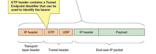
15 E-UTRAN Network interfaces S1 interface: user plane User plane S1 interface or S1-U: Carries user data packets between enodeb and Serving GW, Uses GTP (GPRS Tunneling Protocol) inherited from 2G/GPRS and 3G/UMTS networks top of UDP/IP, with user data encapsulation, No flow control, no error control and no data delivery guaranteed. 15
16 GTP All variants of GTP have certain features in common. The structure of the messages is the same, with a GTP header following the UDP/TCP header. GTPv1 headers contain the following fields: + Bit Version Protocol type Reserved Extension Header Flag Sequence Number Flag 32 TEID N-PDU Number Flag Message Type Total length 64 Sequence number N-PDU number Next extension header type Version: 3-bit field. For GTPv1, this has a value of 1. Protocol Type (PT): 1-bit value that differentiates GTP (value 1) from GTP' (value 0). Reserved a 1-bit reserved field (must be 0). Extension header flag (E): 1-bit value that states whether there is an extension header optional field. Sequence number flag (S): 1-bit value that states whether there is a Sequence Number optional field. N-PDU number flag (PN): 1-bit value that states whether there is a N-PDU number optional field. Message Type: 8-bit field to indicate the type of GTP message. Different types of messages are defined in 3GPP TS section Length a 16-bit field that indicates the length of the payload in bytes (rest of the packet following the mandatory 8-byte GTP header). Includes the optional fields. Tunnel endpoint identifier (TEID): 32-bit(4-octet) field used to multiplex different connections in the same GTP tunnel. Sequence number: optional 16-bit field. Exists if any of the E, S, or PN bits are on. N-PDU number: optional 8-bit field. This field exists if any of the E, S, or PN bits are on. Next extension header type: optional 8-bit field. This field exists if any of the E, S, or PN bits are on. 16

17 GTP principle 17
18 E-UTRAN Network interfaces S1 interface: Control plane Control plane S1 interface, or S1-C: signaling interface supporting a set of features and procedures between enodeb and MME, 4 main groups S1-C signaling procedures: Bearer related procedures: bearer establishment, change and release, Handover procedures: all S1 features related to the mobility of the users between enodebs or with the 2G/3G technologies, NAS (Non Access Stratum) signaling transfer: signaling between a terminal and MME, through S1 interface(enodeb transparent signaling), Paging procedure: used for MT sessions (the MME request from enodeb topageaterminalinagivencell) 18
19 Network and protocol architecture 3. LTE Identities 19
20 User Identities International Mobile Subscriber Identity (IMSI) allocated to each mobile subscriber in every (GSM, UMTS, and EPS) system. VLRs, SGSNs and MMEs may allocate Temporary Mobile Subscriber Identities(X-TMSI) for subscriber identity confidentiality. An MS may be allocated three TMSIs through the: VLR (TMSI) SGSN (P-TMSI) MME (S-TMSI, M-TMSI, part of GUTI, Globally Unique Temporary UE Identity). 20
21 User Identities IMSI is composed of three parts: Mobile Country Code (MCC) consisting of three digits, Mobile Network Code (MNC) consisting of two or three digits for GSM/UMTS applications. Mobile Subscriber Identification Number (MSIN) identifying the mobile subscriber within a PLMN. National Mobile Subscriber Identity (NMSI) = MNC and NMSI. 21
22 User Identities Temporary Mobile Subscriber Identity (TMSI) structure and coding is chosen by agreement between operator and ME manufacturer in order to meet local needs. The TMSI consists of 4 octets. It can be coded using a hexadecimal representation. The network shall not allocate a TMSI with all 32 bits equal to 1, because TMSI must be stored in the SIM, and SIM uses 4 octets with all bits equal to 1 to indicate that no valid TMSI is available. Globally Unique Temporary UE Identity (GUTI ): unambiguous identification of the UE that does not reveal the UE or the user's permanent identity in the Evolved Packet System (EPS). It allows the identification of the MME and network. GUTI=GUMMEI + M-TMSI, where GUMMEI= MCC + MNC + MME Identifier MME Identifier = MME Group ID + MME Code MCC and MNC shall have the same field size as in earlier 3GPP systems. M-TMSIshall be of 32 bits length. MME Group ID shall be of 16 bits length. MME Code shall be of 8 bits length. 22
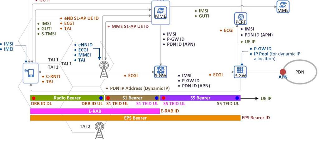
23 LTE Identities ID Meaning Description Structure IMSI PLMN ID International Mobile Subscriber Identity Public Land Mobile Network Identifier Unique identification of mobile (LTE) subscriber Network (MME) gets the PLMN of the subscriber Unique identification of PLMN MCC Mobile Country Code assigned by ITU MNC Mobile Network Code assigned by National Authority Mobile Subscriber MSIN assigned by operator Identification Number GUTI TIN S-TMSI Globally Unique Temporary UE Identity Temporary Identity used in Next Update SAE Temporary Mobile Subscriber Identity To identify a UE between the UE and the MME on behalf of IMSI for security reason GUTI is stored in TIN parameter of UE s MM context. TIN indicates which temporary ID will be used in the next update. To locally identify a UE in short within a MME group (Unique within a MME Pool) IMSI (not more than 15 digits) = PLMN ID + MSIN = MCC + MNC + MSIN PLMN ID (not more than 6 digits) = MCC + MNC 3 digits 2 or 3 digits 9 or 10digits GUTI (not more than 80 bits) = GUMMEI + M- TMSI TIN = GUTI S-TMSI (40 bits) = MMEC + M-TMSI 23
24 LTE Identities ID Meaning Description Structure MME Mobile M-TMSI Unique within a MME 32 bits Subscriber Identity GUMMEI Globally Unique MME Identity To identify a MME uniquely in global GUTI contains GUMMEI MMEI MME Identifier To identify a MME uniquely within a PLMN Operator commissions at enbmmei MMEGI MME Group Identifier Unique within a PLMN MMEC MME Code To identify a MME uniquely within a MME Group. S-TMSI contains MMEC8 C-RNTI Cell-Radio Network Temporary Identifier To identify an UE uniquely in a cell IMEI International Mobile To identify a ME (Mobile Equipment) Equipment Identity uniquely To identify a ME (Mobile Equipment) IMEI/SV IMEI/Software Version uniquely ECGI E-UTRAN Cell Global Identifier To identify a Cell in global (Globally Unique) EPC can know UE location based of ECGI GUMMEI (not more than 48 bits)= PLMN ID + MMEI MMEI (24 bits) = MMEGI + MMEC 16 bits 8 bits 0x0001 ~ 0xFFF3 (16 bits) IMEI (15 digits) = TAC + SNR + CD IMEI/SV (16 digits) = TAC + SNR + SVN ECGI (not more than 52 bits) = PLMN I D+ ECI 24
25 LTE Identities ECI ID Meaning Description Structure E-UTRAN Cell ECI (28 Bits) = enb ID To identify a Cell within a PLMN Identifier + Cell ID PGW ID PDN GW Identity TAI TAC TAI List Tracking Area Identity Tracking Area Code Tracking Area Identity List To identify a specific PDN GW (P- GW) HSS assigns P-GW for PDN (IP network) connection of each UE To identify Tracking Area Globally uniquetai To indicate enbto which Tracking Area the enb belongs (per Cell) Unique within a PLMN16 UE can move into the cells included in TAL list without location update (TA update) Globally unique IP address (4 bytes) or FQDN (variable length) TAI (not more than 32 bits) = PLMN ID + TAC P-GW 16 bits Variable length 25
26 LTE Identities ID Meaning Description Structure To identify an PDN (IP network), that mobile data user wants to communicate with PDN ID PDN Identity (APN) is used to PDN Identify= APN = Packet Data Network determine the P-GW and point of APN.NI + APN.OI Identity interconnection with a PDN (variable length) With APN as query parameter to the DNS procedures, the MME will receive a list of candidate P-GWs, and then a P- GW is selected by MME with policy EPS Bearer ID E-RAB ID DRB ID LBI TEID Evolved Packet System Bearer Identifier E-UTRAN Radio Access Bearer Identifier Data Radio Bearer Identifier Linked EPS Bearer ID Tunnel End Point identifier To identify an EPS bearer (Default or Dedicated) per an UE4 To identify an E-RAB per an UE To identify a DRB per an UE 4 bits 4 bits 4 bits To identify the default bearer associated with a dedicated EPS bearer 4 bits To identify the end point of a GTP 32 bits tunnel when the tunnel is established 26
27 LTE Identities 27
28 Control Plane Protocols 4. Network Entities 28
29 MME MME host the following functions: NAS signaling security AS security control Inter CN node signaling for mobility between 3GPP access networks Tracking Area list management PDN GW and Serving GW selection MME selection for handovers with MME change SGSN selection for handovers to 2G or 3G 3GPP access networks Roaming Authentication Bearer management functions including dedicated bearer establishment Support PWS(which includes ETWS and CMAS) message transmission UE reachability in idle state(including control and paging retransmission) 29
30 S-GW Serving Gateway(S-GW) hosts the following functions: The local Mobility Anchor point for inter-enb handover Mobility anchoring for inter-3gpp mobility E-UTRAN idle mode downlink packet buffering and initiation of network tri ggered service request procedure Lawful Interception Packet routeing and forwarding Transport level packet marking in the uplink and the downlink Accounting on user and QCI granularity for inter-operator charging ULandDLchargingperUE,PDN,andQCI 30
31 P-GW PDN Gateway hosts the following functions: Per-user based packet filtering(by e.g. deep packet inspection) Lawful Interception UE IP address allocation Transport level packet marking in the downlink UL and DL service level charging, gating and rate enforcement DL rate enforcement based on APN-AMBR Credit control for online charging Note The S-GW and P-GW are usually integrated in the same equipment (direct tunnel). Physical separation is done in the case of roaming. 31
32 PCRF HSS PCRF (Policy Control and Charging Rules Function) - Policy control decision-making, - Control the flow-based charging functionalities in the Policy Control Enforcement Function (PCEF), which resides in the P-GW - Provides the QoS authorization (QoS class identifier [QCI] and bit rates) that decides how a certain data flow will be treated in the PCEF and ensures that this is in accordance with the user s subscription profile. HSS (Home Subscriber Server) - Contains users SAE subscription data such as the EPS-subscribed QoS profile and any access restrictions for roaming - Holds information about the PDNs to which the user can connect (in the form of an access point name (APN) (which is a label according to DNS naming conventions describing the access point to the PDN) or a PDN address (indicating subscribed IP address(es)) - Holds dynamic information such as the identity of the MME to which the user is currently attached or registered - Integrates the authentication center (AUC), which generates the vectors for authentication and security keys. 32


33 LTE Entity Functions Summary RR: Radio Resource RRC: Radio Resource Control EMM: Evolved Mobility Management ECM: Evolved Connection Management 33
34 Network and protocol architecture 5. LTE/EPC Bearers 34


35 Control plane protocols Radio Protocol Stack Overview 35
36 RRC Overview (1/2) Main RRC services and functions: System Information Broadcast: Through the logical channel BCCH Related to the access network (Settings related to the radio) or core network(plmnidentity,...) Paging: Through the PCCH(logical channel) Establishment, maintenance and release of an RRC connection between the UE and E-UTRAN: Allocation of temporary identifiers between UE and E-UTRAN Configuration of signaling radio bearer(s) for RRC connection Security functions including key management, Mobility functions including: UE measurement reporting for handover RRC talks directly with PHY to obtain measurement results UE cell selection and reselection and control of cell selection and reselection 36
37 RRC Overview (2/2) Transmission of signaling messages to and from the EPS: NAS Messages (Non Access Stratum) handled transparently by the RRC (Radio Resource Control): control information exchanged between UE and E-UTRAN E-UTRAN RRC significantly simplified compared to UTRAN: Reduction in the number of messages 37
, with a given QoS. Ex.")
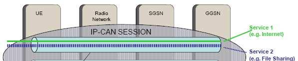
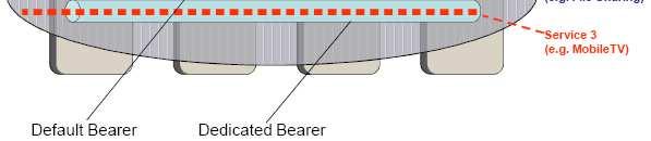
38 Default/Dedicated Bearer Default Bearer vs Dedicated Bearer A default bearer carries all kinds of traffic (no filter) without QoS. It is typically created during the Attach procedure A dedicated bearer carries a specific data flow, identify by the TFT (Traffic Flow Template), with a given QoS. Ex.: Voice, streaming Can be established: During the Attach procedure (depending on the user profile) After the Attach procedure, on demand. 38
39 Default/Dedicated bearer 39
 and the default bearer is setup (always best effort).")

40 Default/Dedicated Bearer When the UE establishes a PDN Connection this creates a logical end to end "pipe" between the UE and the PGW. The UE is assigned an IP address (IPv4 or IPv6) and the default bearer is setup (always best effort). If the UE requires some QoSdifferent than best effort, a dedicated bearer can be setup. This will be a necessity for voice services over LTE for example but could also be used when a streaming session is setup, or a Skype session etc. The network knows that a dedicated beareris needed by DPI, most likely by the PCRFnode. 40

, comply with regulations, prioritize")
41 DPI (Deep Packet Inspection) DPI = HW and SW solution that: Monitors a network's data stream, Identifies protocols and applications, inappropriate URLs, intrusion attempts and malware DPI inspects, reassembles and decompresses incoming packets, analyzes the code and passes data to appropriate applications and services. If malicious URLs or code are detected, the system can block them entirely. DPI can also be used by service providers to offer subscribers different levels of access (such as type of usage, data limits or bandwidth level), comply with regulations, prioritize traffic, adjust loads and gather statistical information. DPI can recognize applications as data passes through the system, allocating each the resources they need. 41
42 Default Bearer QoS Control Total volume limit exceeded Agg gregated bandwidth Cell capacity Aggregated load in the cell Normal users THP=2 THP=2 THP=2 THP=3 Heavy user Heavy users are dynamically downprioritized at network congestion 42
43 Network and protocol architecture 6. Mobile Backhaul /Backbone 43
44 Wireless Backhaul Access Network Handset, PDA or Laptop Copper Fiber Carrier Base Station Mobile Switching Office (provisioning, call routing, etc) Public Switched Telephone Network Source: Fibertower Investor Presentation, April Three Main Transport Methods Copper (T1s) Fiber Microwave Copper/Fiber Hybrid Solution Copper TDM great for voice, not so great for data Fiber Ethernet great for data, allows transition to VOIP 44
45 Wireless Backhaul Infrastructure Trends Fiber quickly replacing copper to meet LTE bandwidth requirements Point-to-point microwave backhauled to fiber to save cost -Ethernet over E1 driving savings, greater data flow and greater reliability 45


46 LTE Architecture: Mobile backhaul trends Convergence of backhaul/backbone In 2G/3G mobile networks, the BSC/RNC perform RRM. They reside at the local switch and the connection between the base station and the controllers is enabled via the backhaul network. The backbone network is not involved and can be functionally separate, being utilized primarily for interconnection of switch. Mobile backhaul is increasingly becoming a strategic investment for service providers (source: World Mobile Backhaul Infrastructure Market, Frost & Sullivan, February 2009) and hence the need for flexibility is ever growing. 46
47 LTE Architecture: The Mobile broadband backhaul Broadband Mobile Network Evolution Backhaul systems designed to serve LTE deployments should address three basic requirements: Higher capacities: Backhaul to a single site should be able scale to 100Mbps and even beyond Lower Latencies: The requirement for 10 millisecond endto-end leads to select a solution that supports extremely low latency AllIP:SupportIPtrafficfromtheget-go. 47
48 Examples of microwave capacities BridgeWave Description Distance Capacity 80 GHz Fast Ethernet extended range 125Mbps Up to 4 Miles(KM) wireless bridge Upgrade to Gig-E 80 GHz Fast Ethernet extended range 125Mbps Up to 5 Miles(8.0KM) wireless bridge Upgrade to Gig-E 80 GHz Fast Ethernet medium range wireless bridge Up to 5 miles(8 km) 100 Mbps 80 GHz Fast Ethernet medium range Up to 6 miles(9.7 km) wireless bridge 100 Mbps 80 GHz Fast Ethernet medium range wireless bridge Up to 4 miles( km) 1000 Mbps 80 GHz Fast Ethernet medium range wireless bridge Up to 5 miles(8 km) 1000 Mbps 80 GHz AdaptRate 100/1000 Mbps extended range wireless bridge Up to 5 miles(8 km) 100/1000 Mbps 80 GHz AdaptRate 100/1000 Mbps extended range wireless bridge Up to 6 miles(9.7 km) 100/1000 Mbps 48

49 Summary The E-UTRAN The E-UTRAN consists of enodebs which provide E-UTRA user plane (PDCP/RLC/MAC/PHY) and control plane (RRC) protocol terminations toward the user equipment(ue). The enbs are interconnected with each other by means of the X2 interface. The enbs connected through S1 interface to the Evolved Packet Core (EPC), more specifically to the Mobility Management Entity (MME) by means of the S1-MME interface and to the Serving Gateway (SGW) by means of the S1-U interface. The EPC(Evolved Packet Core) The LTE architecture defines the Evolved Packet System (EPS) as a combination of the LTE access system(radio part) and an IP-based core network, the Evolved Packet Core(EPC). The EPC is an all-ip mobile core network for LTE, allowing the convergence of packet-based realtime and non-real-time services. All EPS transactions are IP-based: from the mobile handsets, over enode Bs, across the EPC, and throughout the application domain, for both IMS and non-ims. The EPC is a multi-access core IP-based network that enables operators to deploy and operate one common packet core network for 3GPP radio access (LTE, 3G, and 2G) and non-3gpp radio access (HRPD, WLAN, and WiMAX), and fixed access(ethernet, DSL, cable and fiber) LTE Architecture 49
50 Control Plane Protocols 7. Security 50
51 Security Aspects and parameters in LTE Security concerns: As UMTS, UE authentication (USIM: 128 bits key imposed); The internal signaling protection (integrity), signaling and traffic encryption; Additional signaling encryption for RRCandNAS. Safety is enhanced by protecting all entities Hierarchical protection (UE, enb, ASME, HSS, AuC); Ensure transport security on all interfaces. USIM / AuC UE / HSS UE / MME K UPenc K RRCenc K RRCint K NASenc K NASint enodeb RRC K CK, IK K ASME UE / enb IPsec K NASenc K NASint K enb S-GW MME K UPenc K RRCint K RRCenc ASME: Access Security Mangement Entity 51
52 Security Aspects and parameters in LTE Main changes and additions for security in LTE versus 3G: Introduction of a hierarchical key system in which keys can be changed for different purposes, Separation of the security functions for the NAS, Introduction of the concept of forward security: limits thesecurityissueswhenadisclosedkeyisused Additional security functions for 3G and LTE network interconnection 52
 Extended key hierarchy Longer keys Greater protection for backhaul Integrated interworking security for legacy and non-3gpp")
53 Security Aspects and parameters in LTE Characteristics Re-use of UMTS Authentication and Key Agreement (AKA) Use of USIM required (GSM SIM excluded) Extended key hierarchy Longer keys Greater protection for backhaul Integrated interworking security for legacy and non-3gpp networks 53
54 Security Aspects in LTE Encryption is performed at the enodeb. MSPs (Mobile Services Provider) should support encryption within the transport network, especially if using third-party backhaul transport providers or public Internet transport. IPSec tunneling between the enodeb and the security gateway used to secure data and provide QoS to manage the security centrally. 54
55 Security Aspects and parameters in LTE NAS security NAS messages, UEand MMEscope. NAS message communication between UE and MME are Integrityprotected and Ciphered with extra NAS security header. AS security RRC and user plane data, UEand enbscope. PDCP layer in UE and enb side responsible for ciphering and integrity. RRC messages integrity protected and ciphered but U-Plane data is only ciphered. Different Security algorithms (integrity/ciphering) Integrity (EIA: EPS Integrity Algorithm) 0000 EIA0 Null Integrity Protection algorithm EIA1 SNOW 3G EIA2 AES Ciphering (EEA: EPS Encryption Algorithm) 0000 EEA0 Null ciphering algorithm EEA1 SNOW 3G based algorithm EEA2 AES based algorithm 55

 SQN(Sequence")
56 Security Aspects and parameters in LTE Key/parameters distribution in LTE nodes AMF(Authentication Management Field) SQN(Sequence Number) 56
57 Key hierarchy Faster handovers and key changes, independent of AKA Added complexity in handling of security contexts USIM / AuC K UE / HSS CK, IK UE / MME K ASME K NASenc K NASint UE / enb K enb K UPenc K RRCint K RRCenc ASME: Access Security Mangement Entity 57

58 Security Aspects and parameters in LTE Security aspects in LTE 58

59 Security Aspects and parameters in LTE AKA procedure 59
60 Security Aspects and parameters in LTE LTE Ciphering and Integrity Algorithms 60
61 Security Aspects and parameters in LTE Security keys for AS (Access Stratum) User data and control Different from those used in EPC. enodebkeys: K enb : Derived by the terminal and the MME from K ASME ('Master Key') and issued by the MME in enodeb( Master Key ) K enb is used to derive the AS traffic keys and handover key K enb * K enb* : Derived from the terminal and the source from enodeb K enb or valid NH (Next Hop) Duringthe handover, the terminal and the target enodebderive a new K enb * from K enb 61
62 Security Aspects and parameters in LTE K UPenc : Derived from K enb and used to encrypt the user plane K RRCint : Derived from K enb and usedto ensure the integrity of RRC message K RRCenc : DerivedfromK enb and usedto encryptrrc messages NextHop (NH): Intermediate key used to derive K * enb during intra-lte handover security The NCC (NextHop ChainingCounter)determines if the next K * enb must be based on a current K * enb or fresh NH: If no freshnh availabletargetpci (PhysicalCellIdentity) + K enb FreshNH Target PCI + NH 62

63 Security Aspects and parameters in LTE Keys derivation scheme 63
 enb - Does AUTN come from HSS? 1. Check Π(AES1(K, RAND), SQN, AUTN)) 2.")
 RAND, XRES, AUTN, K ASME HSS")
 RES = AES2(K, RAND) (Ck, Ik) = AES3(K, KA RAND) K ASME = F(Ck, Ik,.")
64 Security Aspects and parameters in LTE LTE: Initial Attach K RES, Ck, Ik - Have I seen it before? ATTACH REQUEST (IMSI, SUPPORTED_ALGS) enb - Does AUTN come from HSS? 1. Check Π(AES1(K, RAND), SQN, AUTN)) 2. RES = AES2(K, RAND) 3. (Ck, Ik) = AES3(K, RAND) - Verify OK - Switch on security RES Derive K ASME, K enb... [ OK ] RAND, AUTN OK, SELECTED_ALG, SUPPORTED_ALGS MME AUTH VECT REQUEST (IMSI) RAND, XRES, AUTN, K ASME HSS RAND = RANDOM() Check: RES == XRES?? SQN = SQN + 1 AUTN = AES1(K, RAND, SQN) RES = AES2(K, RAND) (Ck, Ik) = AES3(K, KA RAND) K ASME = F(Ck, Ik,...) F Ke KN-int KN-enc K K enb Protected signaling Protected traffic K enb F KeUP-enc KeRRC-int KeRRC-enc 64

65 Backhauling Security Technologies: IP/MPLS(Backbone), Metro Ethernet(Backhaul) IETF has defined a suite of security protocols: Internet Protocol Security or IPsec. Provide end-to-end security at the packet processing layer to protect the network and higherlayer applications. Secures communications on a host-to-host, network-to-network and network-to-host basis. Ipsec authenticates and encrypts each IP packet within a communications session. IPsec tunnel with BGP/MPLS IPVPN 65
66 Thank you 66
DAY 2. HSPA Systems Architecture and Protocols
 DAY 2 HSPA Systems Architecture and Protocols 1 LTE Basic Reference Model UE: User Equipment S-GW: Serving Gateway P-GW: PDN Gateway MME : Mobility Management Entity enb: evolved Node B HSS: Home Subscriber
System Architecture Evolution
 System Architecture Evolution Contents 2.1 Architecture of LTE 2.2 Communication Protocols 2.3 Example Information Flows 2.4 Bearer Management 2.5 State Diagrams 2.6 Spectrum Allocation 2.1 Architecture
Long Term Evolution - Evolved Packet Core S1 Interface Conformance Test Plan
 Long Term Evolution - Evolved Packet Core S1 Interface Conformance Test Plan Table of Contents 1 SCOPE... 10 2 REFERENCES... 10 3 ABBREVIATIONS... 11 4 OVERVIEW... 14 5 TEST CONFIGURATION... 16 5.1 NETWORK
Simulation of LTE Signaling
 Simulation of LTE Signaling 1 Florin SANDU, 2 Szilárd CSEREY, 3 Eugen MILE-CIOBANU 1 "Transilvania University of Brasov Bd Eroilor nr. 29A RO-500036 Brasov sandu@unitbv.ro, 2,3 SIEMENS Program and System
LTE Security How Good Is It?
 SESSION ID: TECH-RO3 LTE Security How Good Is It? Jeffrey Cichonski IT Specialist (Security) National Institute of Standards & Technology @jchonski Joshua Franklin IT Specialist (Security) National Institute
Communication and Distributed Systems Seminar on : LTE Security. By Anukriti Shrimal May 09, 2016
 Communication and Distributed Systems Seminar on : LTE Security By Anukriti Shrimal May 09, 2016 LTE network with interfaces LTE Security 2 Contents LTE Security : Why, What, How EPS Architecture Design
UMTS Addresses and Identities Mobility and Session Management
 UMTS Addresses and Identities Mobility and Session Management - Numbering, addressing and location identities - UE modes - Mobility management - Session management and QoS Numbering, Addressing and Location
POWER-ON AND POWER-OFF PROCEDURES
 POWER-ON AND POWER-OFF PROCEDURES TABLE OF CONTENTS 1. Power-On Sequence 2. Network and Cell Selection 3. RRC Connection Establishment 4. Attach Procedure 5. Detach Procedure 1. POWER-ON SEQUENCE The following
E. The enodeb performs the compression and encryption of the user data stream.
 Volume: 140 Questions Question No: 1 Which of the following statements is FALSE regarding the enodeb? A. The enodebs maybe interconnect TEID with each other via anx2 interface. B. The enodeb is an element
MSF Architecture for 3GPP Evolved Packet System (EPS) Access MSF-LTE-ARCH-EPS-002.FINAL
 Access MSF-LTE-ARCH-EPS-002.FINAL") MSF Architecture for 3GPP Evolved Packet System (EPS) Access MSF-LTE-ARCH-EPS-002.FINAL MultiService Forum Architecture Agreement Contribution Number: Document Filename: Working Group: Title: Editor: Contact
MSF Architecture for 3GPP Evolved Packet System (EPS) Access MSF-LTE-ARCH-EPS-002.FINAL MultiService Forum Architecture Agreement Contribution Number: Document Filename: Working Group: Title: Editor: Contact
07/08/2016. Sami TABBANE. I. Introduction II. Evolved Packet Core III. Core network Dimensioning IV. Summary
 Core network and transmission dimensioning Sami TABBANE 1 CONTENTS I. Introduction II. Evolved Packet Core III. Core network Dimensioning IV. Summary 2 1 CONTENTS I. Introduction 3 Introduction LTE Commercialization
LTE EPC Emulators v10.0 Release Notes - Page 1 of 15 -
 LTE EPC Emulators v10.0 Release Notes - Page 1 of 15 - Version 10.0.0.7 Release Date: Feb 24, 2014 Components 1. LTE Emulators : MME (with internal HSS), SGW and PGW (with internal PCRF) 1. LTE Emulators
IT Certification Exams Provider! Weofferfreeupdateserviceforoneyear! h ps://www.certqueen.com
 IT Certification Exams Provider! Weofferfreeupdateserviceforoneyear! h ps://www.certqueen.com Exam : 4A0-M02 Title : Alcatel-Lucent Mobile Gateways for the LTE Evolved Packet Core Version : Demo 1 / 7
ETSI TS V ( )
") TS 133 401 V10.3.0 (2012-07) Technical Specification Digital cellular telecommunications system (Phase 2+); Universal Mobile Telecommunications System (UMTS); LTE; 3GPP System Architecture Evolution (SAE);
TS 133 401 V10.3.0 (2012-07) Technical Specification Digital cellular telecommunications system (Phase 2+); Universal Mobile Telecommunications System (UMTS); LTE; 3GPP System Architecture Evolution (SAE);
GTP-based S2b Interface Support on the P-GW and SAEGW
 GTP-based S2b Interface Support on the P-GW and SAEGW This chapter describes the GTP-based S2b interface support feature on the standalone P-GW and the SAEGW. Feature, page 1 How the S2b Architecture Works,
5G NSA for MME. Feature Summary and Revision History
 Feature Summary and Revision History, on page 1 Feature Description, on page 2 How It Works, on page 5 Configuring, on page 10 Monitoring and Troubleshooting, on page 13 Feature Summary and Revision History
3GPP security hot topics: LTE/SAE and Home (e)nb
nb") 3GPP security hot topics: LTE/SAE and Home (e)nb Valtteri Niemi 3GPP SA3 (Security) chairman Nokia Research Center, Lausanne, Switzerland Marc Blommaert 3GPP LTE/SAE security rapporteur Devoteam Telecom
3GPP security hot topics: LTE/SAE and Home (e)nb Valtteri Niemi 3GPP SA3 (Security) chairman Nokia Research Center, Lausanne, Switzerland Marc Blommaert 3GPP LTE/SAE security rapporteur Devoteam Telecom
Mobile Network Evolution Part 2
 Mobile Network Evolution Part 2 From UMTS to LTE or How to Further Increase Network Capacity and QoS Andreas Mitschele-Thiel Advanced Mobile Communication Networks 1 Outline Evolution from Circuit Switching
IxLoad LTE Evolved Packet Core Network Testing: enodeb simulation on the S1-MME and S1-U interfaces
 IxLoad LTE Evolved Packet Core Network Testing: enodeb simulation on the S1-MME and S1-U interfaces IxLoad is a full-featured layer 4-7 test application that provides realworld traffic emulation testing
3GPP TS V ( )
") TS 33.401 V11.5.0 (2012-09) Technical Specification 3rd Generation Partnership Project; Technical Specification Group Services and System Aspects; System Architecture Evolution (SAE); Security architecture
TS 33.401 V11.5.0 (2012-09) Technical Specification 3rd Generation Partnership Project; Technical Specification Group Services and System Aspects; System Architecture Evolution (SAE); Security architecture
UMTS System Architecture and Protocol Architecture
 UMTS System Architecture and Protocol Architecture Overview on overall system architecture UMTS network architecture and elements Mobile station High-level functions UMTS domains and strata UMTS/GPRS protocol
Mobile NW Architecture Evolution
 Mobile NW Architecture Evolution Prof. Tarik Taleb School of Electrical Engineering Aalto University Mobile Generations AMPS, NMT, TACS 1G 2G 3G 4G ~1980 ~1990 ~2000 ~2010 The foundation of mobile telephony
Basic SAE Management Technology for Realizing All-IP Network
 LTE SAE EPC Special Articles on SAE Standardization Technology Basic SAE Management Technology for Realizing All-IP Network The standardization of 3GPP Release 8 brings new provisions for All-IP networks
Temporary Document Page 2 - switches off, the allocated resources and PCC rules information of PDN GWs used by the UE in non- network will not be dele
 Temporary Document Page 1 - TSG SA WG2 Architecture S2#58 S2-072558 25-29 June 2007 Orlando, FL, USA Source: Huawei Title: Attach Type in attach procedure Document for: Discussion / Approval Agenda Item:
ETSI TS V8.3.0 ( ) Technical Specification
 Technical Specification") TS 124 301 V8.3.0 (2009-09) Technical Specification Universal Mobile Telecommunications System (UMTS); LTE; Non-Access-Stratum (NAS) protocol for Evolved Packet System (EPS); Stage 3 (3GPP TS 24.301 version
TS 124 301 V8.3.0 (2009-09) Technical Specification Universal Mobile Telecommunications System (UMTS); LTE; Non-Access-Stratum (NAS) protocol for Evolved Packet System (EPS); Stage 3 (3GPP TS 24.301 version
Dedicated Core Networks on MME
 This chapter describes the Dedicated Core Networks feature in the following sections: Feature Summary and Revision History, on page 1 Feature Description, on page 2 How It Works, on page 4 Configuring
Virtual Evolved Packet Core (VEPC) Placement in the Metro Core- Backhual-Aggregation Ring BY ABHISHEK GUPTA FRIDAY GROUP MEETING OCTOBER 20, 2017
 Placement in the Metro Core- Backhual-Aggregation Ring BY ABHISHEK GUPTA FRIDAY GROUP MEETING OCTOBER 20, 2017") Virtual Evolved Packet Core (VEPC) Placement in the Metro Core- Backhual-Aggregation Ring BY ABHISHEK GUPTA FRIDAY GROUP MEETING OCTOBER 20, 2017 LTE: All-IP, simplified network architecture [1] Introduction
Virtual Evolved Packet Core (VEPC) Placement in the Metro Core- Backhual-Aggregation Ring BY ABHISHEK GUPTA FRIDAY GROUP MEETING OCTOBER 20, 2017 LTE: All-IP, simplified network architecture [1] Introduction
Exam Questions 4A0-M02
 Exam Questions 4A0-M02 Alcatel-Lucent Mobile Gateways for the LTE Evolved Packet Core https://www.2passeasy.com/dumps/4a0-m02/ 1.Which of the following statements is FALSE regarding the enodeb? A. The
Certkiller 4A0-M02 140q
 Certkiller 4A0-M02 140q Number: 4A0-M02 Passing Score: 800 Time Limit: 120 min File Version: 16.5 http://www.gratisexam.com/ 4A0-M02 Alcatel-Lucent Mobile Gateways for the LTE Evolved Packet Core Added
5G Non Standalone for SAEGW
 This chapter describes the 5G Non Standalone (NSA) feature in the following sections: Feature Summary and Revision History, on page 1 Feature Description, on page 2 How It Works, on page 3 Configuring
1.1 Beyond 3G systems
 1 Introduction The cellular wireless communications industry witnessed tremendous growth in the past decade with over four billion wireless subscribers worldwide. The first generation (1G) analog cellular
Dedicated Core Networks on MME
 This chapter describes the Dedicated Core Networks feature in the following sections: Feature Summary and Revision History, page 1 Feature Description, page 2 How It Works, page 5 Configuring DECOR on
LTE Training LTE (Long Term Evolution) Training Bootcamp, Crash Course
 Training Bootcamp, Crash Course") LTE Training LTE (Long Term Evolution) Training Bootcamp, Crash Course Why should you choose LTE Training? LTE Training is an intensive learning experience that cover the essential elements of Long Term
LTE Training LTE (Long Term Evolution) Training Bootcamp, Crash Course Why should you choose LTE Training? LTE Training is an intensive learning experience that cover the essential elements of Long Term
UNIK4230: Mobile Communications Spring Semester, Per Hj. Lehne
 UNIK4230: Mobile Communications Spring Semester, 2015 Per Hj. Lehne per-hjalmar.lehne@telenor.com 916 94 909 Network Architecture and Functionality 5 February 2015 Contents Network Architecture Protocol
Mobile Network Evolution Part 2
 Mobile Network Evolution Part 2 From UMTS to LTE or How to Further Increase Network Capacity and QoS Andreas Mitschele-Thiel Advanced Mobile Communication Networks 1 Outline Evolution from Circuit Switching
3GPP TS V ( )
") TS 29.274 V8.10.0 (2011-06) Technical Specification 3rd Generation Partnership Project; Technical Specification Group Core Network and Terminals; Evolved Packet System (EPS); Evolved General Packet Radio
TS 29.274 V8.10.0 (2011-06) Technical Specification 3rd Generation Partnership Project; Technical Specification Group Core Network and Terminals; Evolved Packet System (EPS); Evolved General Packet Radio
MME SGW PGW. 17-Feb-14 21:15 (Page 1) This sequence diagram was generated with EventStudio Sytem Designer -
 This sequence diagram was generated with EventStudio Sytem Designer -") LTE Mobile Network Core Network 17-Feb-14 21:15 (Page 1) This sequence diagram was generated with EventStudio Sytem Designer - http://www.eventhelix.com/eventstudio/ UE is handed over using an S1 handover
LTE Mobile Network Core Network 17-Feb-14 21:15 (Page 1) This sequence diagram was generated with EventStudio Sytem Designer - http://www.eventhelix.com/eventstudio/ UE is handed over using an S1 handover
3GPP TS V9.3.0 ( )
") TS 29.274 V9.3.0 (2010-06) Technical Specification 3rd Generation Partnership Project; Technical Specification Group Core Network and Terminals; Evolved Packet System (EPS); Evolved General Packet Radio
TS 29.274 V9.3.0 (2010-06) Technical Specification 3rd Generation Partnership Project; Technical Specification Group Core Network and Terminals; Evolved Packet System (EPS); Evolved General Packet Radio
Delivery of Voice and Text Messages over LTE 13 年 5 月 27 日星期 一
 Delivery of Voice and Text Messages over LTE 1. The Market for Voice and SMS 2. Third Party Voice over IP 3. The IP Multimedia Subsystem 4. Circuit Switched Fallback 5. VoLGA LTE was designed as a data
Small Data over NAS, S11-U and SGi Interfaces
 The MME support for small data transmission over NAS, S11-U and SGi interfaces is described in this chapter. Feature Summary and Revision History, page 1 Feature Description, page 2 How it Works, page
Quality of Service, Policy and Charging
 Quality of Service, Policy and Charging Contents 1. Policy and Charging Control! 2. Session Management Procedures! 3. Charging and Billing 1. Policy and Charging Control 1.1 Introduction! 1.2 Quality of
LTE Radio Interface Architecture. Sherif A. Elgohari
 LTE Radio Interface Architecture Sherif A. Elgohari (selgohari@ieee.org) Agenda Overall System Architecture Radio Protocol Architecture Radio Link Control Medium Access Control Physical Layer Control Plan
Direct Tunnel for 4G (LTE) Networks
 Networks") This chapter briefly describes support for direct tunnel (DT) functionality over an S12 interface for a 4G (LTE) network to optimize packet data traffic. Cisco LTE devices (per 3GPP TS 23.401 v8.3.0) supporting
This chapter briefly describes support for direct tunnel (DT) functionality over an S12 interface for a 4G (LTE) network to optimize packet data traffic. Cisco LTE devices (per 3GPP TS 23.401 v8.3.0) supporting
Version LTE Emulators v10.2 Release Notes - Page 1 of 16 - Release Date: Aug 28, Resolved Issues
 Version 10.2.0.15 Release Date: Aug 28, 2015 Resolved Issues LTE Emulators v10.2 Release Notes - Page 1 of 16-11336 MME does not release previous S1 association when UE Context Release Request procedure
ELEC-E7230 Mobile Communication Systems
 ELEC-E7230 Mobile Communication Systems Lecture 1 Prof. Tarik Taleb School of Electrical Engineering Aalto University Work Plan Content Mobile Network Architectures Evolution MN Arch. Evolution: 2G to
ETSI TS V ( )
") TS 129 274 V8.11.0 (2012-01) Technical Specification Universal Mobile Telecommunications System (UMTS); LTE; 3GPP Evolved Packet System (EPS); Evolved General Packet Radio Service (GPRS) Tunnelling Protocol
TS 129 274 V8.11.0 (2012-01) Technical Specification Universal Mobile Telecommunications System (UMTS); LTE; 3GPP Evolved Packet System (EPS); Evolved General Packet Radio Service (GPRS) Tunnelling Protocol
ETSI TS V (201
 TS 123 401 V13.5.0 (201 16-03) TECHNICAL SPECIFICATION LTE; General Packet Radio Service (GPRS) enhancements for Evolved Universal Terrestrial Radio Access Network (E-UTRAN) access (3GPP TS 23.401 version
3GPP TS V ( )
") TS 29.281 V11.5.0 (2012-12) Technical Specification 3rd Generation Partnership Project; Technical Specification Group Core Network and Terminals; General Packet Radio System (GPRS) Tunnelling Protocol
TS 29.281 V11.5.0 (2012-12) Technical Specification 3rd Generation Partnership Project; Technical Specification Group Core Network and Terminals; General Packet Radio System (GPRS) Tunnelling Protocol
Configuring GPRS Tunneling Protocol Support
 The GPRS Tunneling Protocol Support feature provides firewall support for General Packet Radio Switching (GPRS) Tunneling Protocol (GTP). GPRS is a data network architecture, which integrates with existing
A TUTORIAL ON THE FUNTIONALITY ON CORE NETWORK MOBILITY JATINDER JASBIR SINGH. Presented to the Faculty of the Graduate School of
 A TUTORIAL ON THE FUNTIONALITY ON CORE NETWORK MOBILITY by JATINDER JASBIR SINGH Presented to the Faculty of the Graduate School of The University of Texas at Arlington in Partial Fulfillment of the Requirements
Agenda. Introduction Roaming Scenarios. Other considerations. Data SMS Voice IMS
 LTE Roaming Agenda Introduction Roaming Scenarios Data SMS Voice IMS Other considerations LTE Roaming Situation None of Verizon LTE subscribers can roam on another LTE network, not even on other 700 MHz
INTRODUCTION TO LTE. ECE MOBILE COMMUNICATION Monday, 25 June 2018
 INTRODUCTION TO LTE ECE 2526 - MOBILE COMMUNICATION Monday, 25 June 2018 1 WHAT IS LTE? 1. LTE stands for Long Term Evolution and it was started as a project in 2004 by the Third Generation Partnership
3GPP TS V ( )
") TS 23.251 V10.1.0 (2011-03) Technical Specification 3rd Generation Partnership Project; Technical Specification Group Services and System Aspects; Network Sharing; Architecture and functional description
TS 23.251 V10.1.0 (2011-03) Technical Specification 3rd Generation Partnership Project; Technical Specification Group Services and System Aspects; Network Sharing; Architecture and functional description
Test Plan for LTE Interoperability
 Test Plan for LTE Interoperability Revision 1.0 December 2011 2011 CTIA The Wireless Association. All rights reserved. CTIA has granted a license to CTIA Authorized Testing Laboratories to use this Test
3GPP TS V9.5.0 ( )
") Technical Specification 3rd Generation Partnership Project; Technical Specification Group Core Network and Terminals; Evolved Packet System (EPS); Optimized Handover Procedures and Protocols between E-UTRAN
Technical Specification 3rd Generation Partnership Project; Technical Specification Group Core Network and Terminals; Evolved Packet System (EPS); Optimized Handover Procedures and Protocols between E-UTRAN
3GPP. 3GPP Roadmap. Release 99 Release 4 Release 5 Release 6 Release 7 Release 8. Khaled Alutaibi
 3GPP Release 99 Release 4 Release 5 Release 6 Release 7 Release 8 Khaled Alutaibi LOGO 976452 3GPP Roadmap Radio Access Air Interface Principles Release99 The main improvement of UMTS compared to GSM in
Dimensioning, configuration and deployment of Radio Access Networks. part 1: General considerations. Mobile Telephony Networks
 Dimensioning, configuration and deployment of Radio Access Networks. part 1: General considerations Mobile Telephony Networks 1 The Evolution of Mobile Telephony 1st Generation 2nd 3rd 4th Analogue Voice
Multi-RAT Heterogeneous Networks. Presenter: S. Vasudevan, Technical Manager, Advanced Technology Standards
 Multi-RAT Heterogeneous Networks Presenter: S. Vasudevan, Technical Manager, Advanced Technology Standards What are Multi-RAT Heterogeneous Networks Integrated Networks supporting a range of cell sizes
ETSI TS V9.2.0 ( ) Technical Specification
 Technical Specification") TS 123 401 V9.2.0 (2009-10) Technical Specification LTE; General Packet Radio Service (GPRS) enhancements for Evolved Universal Terrestrial Radio Access Network (E-UTRAN) access (3GPP TS 23.401 version
TS 123 401 V9.2.0 (2009-10) Technical Specification LTE; General Packet Radio Service (GPRS) enhancements for Evolved Universal Terrestrial Radio Access Network (E-UTRAN) access (3GPP TS 23.401 version
3GPP TS V ( )
") Technical Specification 3 rd Generation Partnership Project; Technical Specification Group Radio Access Network; Evolved Universal Terrestrial Radio Access Network (E-UTRAN); S1 Application Protocol (S1AP)
Technical Specification 3 rd Generation Partnership Project; Technical Specification Group Radio Access Network; Evolved Universal Terrestrial Radio Access Network (E-UTRAN); S1 Application Protocol (S1AP)
Operator Policy. What Operator Policy Can Do. A Look at Operator Policy on an SGSN
 The proprietary concept of an operator policy, originally architected for the exclusive use of an SGSN, is non-standard and currently unique to the ASR 5x00. This optional feature empowers the carrier
This chapter describes the support of Non-IP PDN on P-GW and S-GW.
 This chapter describes the support of Non-IP PDN on P-GW and S-GW. Feature Summary and Revision History, page 1 Feature Description, page 2 How It Works, page 2 Configuring Non-IP PDN, page 8 Monitoring
T325 Summary T305 T325 B BLOCK 2 4 PART III T325. Session 1 Block III Part 2 Section 2 - Continous Network Architecture. Dr. Saatchi, Seyed Mohsen
 T305 T325 B BLOCK 2 4 PART III T325 Summary Session 1 Block III Part 2 Section 2 - Continous Network Architecture [Type Dr. Saatchi, your address] Seyed Mohsen [Type your phone number] [Type your e-mail
AAA Server-provided 3GPP-User-Location-Information Support
 AAA Server-provided 3GPP-User-Location-Information Support The following topics are discussed: Feature Description, page 1 How AAA Server-provided 3GPP-User-Location-Information Works, page 2 Configuring
Access Restriction based on Regional Zone Code
 This chapter describes access restrictions based on regional zone codes, which are configured under a TAI-Object. Feature Description, page 1 How It Works, page 1 Configuring, page 5 Monitoring and Troubleshooting
GGSN Pooling Support for Firewalls
 The feature enhances the General Packet Radio Switching (GPRS) Tunneling Protocol (GTP) feature by adding load balancing support. GTP supports the inspection of control traffic that is designated to a
3GPP TS V9.2.0 ( )
") TS 29.281 V9.2.0 (2010-03) Technical Specification 3rd Generation Partnership Project; Technical Specification Group Core Network and Terminals; General Packet Radio System (GPRS) Tunnelling Protocol User
TS 29.281 V9.2.0 (2010-03) Technical Specification 3rd Generation Partnership Project; Technical Specification Group Core Network and Terminals; General Packet Radio System (GPRS) Tunnelling Protocol User
3GPP TS V ( )
") TS 29.274 V11.13.0 (2014-12) Technical Specification 3rd Generation Partnership Project; Technical Specification Group Core Network and Terminals; Evolved Packet System (EPS); Evolved General Packet Radio
TS 29.274 V11.13.0 (2014-12) Technical Specification 3rd Generation Partnership Project; Technical Specification Group Core Network and Terminals; Evolved Packet System (EPS); Evolved General Packet Radio
5G NSA(Non-Standalone Architecture)
") This chapter describes the following topics: Feature Summary and Revision History, page 1 Feature Description, page 2 How It Works, page 2 Configuring DCNR, page 5 Monitoring and Troubleshooting, page
This chapter describes the following topics: Feature Summary and Revision History, page 1 Feature Description, page 2 How It Works, page 2 Configuring DCNR, page 5 Monitoring and Troubleshooting, page
Virtual Mobile Core Placement for Metro Area BY ABHISHEK GUPTA FRIDAY GROUP MEETING NOVEMBER 17, 2017
 Virtual Mobile Core Placement for Metro Area BY ABHISHEK GUPTA FRIDAY GROUP MEETING NOVEMBER 17, 2017 Motivation Volume of data to be transported in across a mobile network keeps increasing Proprietary
Delivery of Voice and Text Messages over LTE
 Delivery of Voice and Text Messages over LTE 1. The Market for Voice and SMS 2. Third Party Voice over IP 3. The IP Multimedia Subsystem 4. Circuit Switched Fallback 5. VoLGA Two main approaches to the
LEGAL DISCLAIMERS AND NOTICES
 CBRS Network Service Technical Specifications CBRSA-TS-1002 V1.0.0 February 1, 2018 LEGAL DISCLAIMERS AND NOTICES THIS SPECIFICATION IS PROVIDED "AS IS," WITHOUT ANY REPRESENTATION OR WARRANTY OF ANY KIND,
3gpp Based LTE Network Architecture for Broad band Wireless Communication
 Volume 118 No. 24 2018 ISSN: 1314-3395 (on-line version) url: http://www.acadpubl.eu/hub/ http://www.acadpubl.eu/hub/ 3gpp Based LTE Network Architecture for Broad band Wireless Communication T.Vasu deva
S11U Interface Support on S-GW for CIoT Devices
 SU Interface Support on S-GW for CIoT Devices Feature Summary and Revision History, page Feature Description, page 2 How It Works, page 4 Standards Compliance, page 9 Configuring SU Interface Support on
ETSI TS V (201
 TS 123 401 V13.6.1 (201 16-05) TECHNICAL SPECIFICATION LTE; General Packet Radio Service (GPRS) enhancements for Evolved Universal Terrestrial Radio Accesss Network (E-UTRAN) access (3GPP TS 23.401 version
ETSI TS V ( )
") TS 123 251 V10.5.0 (2013-01) Technical Specification Universal Mobile Telecommunications System (UMTS); LTE; Network sharing; Architecture and functional description (3GPP TS 23.251 version 10.5.0 Release
TS 123 251 V10.5.0 (2013-01) Technical Specification Universal Mobile Telecommunications System (UMTS); LTE; Network sharing; Architecture and functional description (3GPP TS 23.251 version 10.5.0 Release
Interoperability Test Plan for LTE Wireless Devices
 Interoperability Test Plan for LTE Wireless Devices Version 2.1 February 2017 2017 CTIA - The Wireless Association. All rights reserved. CTIA hereby grants to CTIA Authorized Testing Laboratories (CATLs),
3GPP TS V ( )
") TS 23.251 V13.1.0 (2015-03) Technical Specification 3rd Generation Partnership Project; Technical Specification Group Services and System Aspects; Network Sharing; Architecture and functional description
TS 23.251 V13.1.0 (2015-03) Technical Specification 3rd Generation Partnership Project; Technical Specification Group Services and System Aspects; Network Sharing; Architecture and functional description
SA WG2 Temporary Document Page 2 - Besides these advantages, it is possible to use the based mechanism to consider aspects such as: Node capabilities
 SA WG2 Temporary Document Page 1 - TSG SA WG2 Architecture S2#57 S2-071738 23-27 April 2007 Beijing, China Formatted: Width: 8.5", Height: 11" Source: Title: Document for: Ericsson GW selection for LTE
show mme show mme-service all This chapter includes the show mme command output tables.
 This chapter includes the command output tables. -service all, page 1 -service db record all, page 16 -service db record imsi, page 17 -service db statistics, page 21 -service enodeb-association full,
3GPP TS V ( )
") TS 23.303 V12.7.0 (2015-12) Technical Specification 3rd Generation Partnership Project; Technical Specification Group Services and System Aspects; Proximity-based services (); Stage 2 (Release 12) The
TS 23.303 V12.7.0 (2015-12) Technical Specification 3rd Generation Partnership Project; Technical Specification Group Services and System Aspects; Proximity-based services (); Stage 2 (Release 12) The
3GPP TS V ( )
") Technical Specification 3rd Generation Partnership Project; Technical Specification Group Core Network and Terminals; Evolved Packet System (EPS); Sv interface (MME to MSC, and SGSN to MSC) for SRVCC ()
Technical Specification 3rd Generation Partnership Project; Technical Specification Group Core Network and Terminals; Evolved Packet System (EPS); Sv interface (MME to MSC, and SGSN to MSC) for SRVCC ()
WIRELESS SYSTEM AND NETWORKING
 LECTURE 6 WIRELESS SYSTEM AND NETWORKING References: Rappaport (Chapter 9 and 10) Bernhard (Chapter 3, 4 and 5) Garg (Chapter 8 and 9) Kaarenen (Chapter 1-5 and 9) WIRELESS EVOLUTION Japan Europe Americas
ETSI TS V9.1.0 ( ) Technical Specification
 Technical Specification") TS 132 426 V9.1.0 (2010-01) Technical Specification LTE; Telecommunication management; Performance Management (PM); Performance measurements Evolved Packet Core (EPC) network (3GPP TS 32.426 version 9.1.0
TS 132 426 V9.1.0 (2010-01) Technical Specification LTE; Telecommunication management; Performance Management (PM); Performance measurements Evolved Packet Core (EPC) network (3GPP TS 32.426 version 9.1.0
3GPP TS V ( )
") TS 23.401 V10.4.0 (2011-06) Technical Specification 3rd Generation Partnership Project; Technical Specification Group Services and System Aspects; General Packet Radio Service (GPRS) enhancements for Evolved
TS 23.401 V10.4.0 (2011-06) Technical Specification 3rd Generation Partnership Project; Technical Specification Group Services and System Aspects; General Packet Radio Service (GPRS) enhancements for Evolved
New service standardisation approach
 UMTS Part of the IMT 2000 family 3 nd Generation digital cellular mobile system Approximately old (GSM + GPRS) core network + new radio access network (UTRAN) including new radio interface (WCDMA) New
Requirement Plan Plan Name: LTE_Data_Retry Plan Id: LTEDATARETRY Version Number: 31 Release Date: June 2018
 Requirement Plan Requirement Plan Plan Name: Plan Id: LTEDATARETRY Version Number: 31 Release Date: June 2018 This document provides initial information related to Verizon Wireless Long Term Evolution
End-to-end IP Service Quality and Mobility - Lecture #6 -
 End-to-end IP Quality and Mobility - Lecture #6 - Special Course in Networking Technology S-38.215 vilho.raisanen@nokia.com Planned contents & draft schedule 1. Introduction Jan 13th 2. Characteristics
3G TS V3.1.0 ( )
") Technical Specification 3rd Generation Partnership Project; Technical Specification Group Core Network; General Packet Radio Service (GPRS); GPRS Tunnelling Protocol (GTP) across the Gn and Gp Interface
Technical Specification 3rd Generation Partnership Project; Technical Specification Group Core Network; General Packet Radio Service (GPRS); GPRS Tunnelling Protocol (GTP) across the Gn and Gp Interface
GPRS and UMTS T
 GPRS and UMTS T-110.2100 Global Packet Radio Service GPRS uses the time slots not used for circuit switched services Data rate depends on the availability of free time slots GPRS uses the multislot technique,
show mme show mme-service all This chapter includes the show mme command output tables.
 This chapter includes the command output tables. -service all, page 1 -service db record all, page 17 -service db record imsi, page 18 -service db statistics, page 22 -service enodeb-association full,
REFERENCE ARCHITECTURE FOR END-TO-END QOS IN HETEROGENEOUS WIRELESS NETWORK ENVIRONMENTS
 REFERENCE ARCHITECTURE FOR END-TO-END QOS IN HETEROGENEOUS WIRELESS NETWORK ENVIRONMENTS Sandra Frei 1, 2, Woldemar Fuhrmann 3, Andreas Rinkel 2 and Bogdan Ghita 1 1 Centre for Information Security and
P-GW Service Configuration Mode Commands
 Service Configuration Mode Commands The (PDN Gateway) Service Configuration Mode is used to create and manage the relationship between specified services used for either GTP or PMIP network traffic. Exec
ETSI TS V8.3.0 ( ) Technical Specification
 Technical Specification") TS 123 251 V8.3.0 (2011-03) Technical Specification Universal Mobile Telecommunications System (UMTS); LTE; Network sharing; Architecture and functional description (3GPP TS 23.251 version 8.3.0 Release
TS 123 251 V8.3.0 (2011-03) Technical Specification Universal Mobile Telecommunications System (UMTS); LTE; Network sharing; Architecture and functional description (3GPP TS 23.251 version 8.3.0 Release
ETSI TS V ( )
") TS 123 285 V14.2.0 (2017-05) TECHNICAL SPECIFICATION Universal Mobile Telecommunications System (UMTS); LTE; Architecture enhancements for V2X services (3GPP TS 23.285 version 14.2.0 Release 14) 1 TS 123
TS 123 285 V14.2.0 (2017-05) TECHNICAL SPECIFICATION Universal Mobile Telecommunications System (UMTS); LTE; Architecture enhancements for V2X services (3GPP TS 23.285 version 14.2.0 Release 14) 1 TS 123
LTE Backhaul Considerations. June 25,
 LTE Backhaul Considerations June 25, 2012 1 AGENDA LTE Requirements and Backhaul Considerations Backhaul Framework and Architecture How to Manage the Network Evolution 2 LTE Business model challenge imperatives:
ETSI TS V8.6.0 ( ) Technical Specification
 Technical Specification") Technical Specification Universal Mobile Telecommunications System (UMTS); LTE; 3GPP Evolved Packet System (EPS); Optimized handover procedures and protocols between E-UTRAN access and cdma2000 HRPD Access;
Technical Specification Universal Mobile Telecommunications System (UMTS); LTE; 3GPP Evolved Packet System (EPS); Optimized handover procedures and protocols between E-UTRAN access and cdma2000 HRPD Access;
Network Architecture for LTE and Wi-Fi Interworking
 Netmanias Technical Document: Network Architecture for and Interworking www.netmanias.com www.nmcgroups.com Network Architecture for and Interworking August 16, 2012 Chris Yoo +82-2-3444-5747, +82-10-3229-1852
ETSI TS V9.2.0 ( ) Technical Specification
 Technical Specification") Technical Specification Universal Mobile Telecommunications System (UMTS); LTE; Optimized Handover Procedures and Protocols between EUTRAN Access and cdma2000 HRPD Access () 1 Reference RTS/TSGC-0429276v920
Technical Specification Universal Mobile Telecommunications System (UMTS); LTE; Optimized Handover Procedures and Protocols between EUTRAN Access and cdma2000 HRPD Access () 1 Reference RTS/TSGC-0429276v920
Architecture and Protocols of EPC-LTE with relay
 Architecture and Protocols of EPC-LTE with relay Yangyang Chen, Xavier Lagrange To cite this version: Yangyang Chen, Xavier Lagrange. Architecture and Protocols of EPC-LTE with relay. 13360. 2013, pp.25.