PowerWorld s Experience Using Real-Time Power System Models
|
|
|
- Tyrone Bishop
- 6 years ago
- Views:
Transcription
1 PowerWorld s Experience Using Real-Time Power System Models Presented by: James Weber, Ph.D. Director of Software Development February 28, South First Street Champaign, Illinois (217) ext 13 weber@powerworld.com
2 PowerWorld s History of Full-Topology Models PowerWorld Simulator 1996 Planning software focused on Bus-Branch Models PowerWorld Retriever 2000 Real-time visualization software Many pilot projects with this worked by exporting a bus/branch model from the EMS (RAW file) This was not a sustainable model for customers PowerWorld Retriever 2006 ISO-New England started work on using the data already managed in their Areva EMS tool Cases only initially, but progressed to reading their EMS one-lines This was clearly the better approach and other real-time customers followed 2
3 PowerWorld s History of Full-Topology Models PowerWorld Simulator Integrated Topology Processing 2010 BPA real time operations started using the direct export from their EMS Expanding data imports with Peak Reliability 2016 This is all data that was already maintained at Peak so we are just plugging into their existing processes Direct read of the Contingency record Direct read of the Remedial Action Scheme definitions Direct import of 1000s of maintained substation topology oneline diagrams Direct import of various overview diagrams Direct import of 1000s of scheduled outages as well 3
4 Full Topology Models exist today: EMS System Models Industry has spent 30 years building the models More importantly: maintaining these models Maintained by an existing large staff of engineers (dozens) More than just the models Oneline diagrams Contingency definitions Remedial Action Scheme definitions SCADA measurements Much more frequent updates than power system planners realize Often done weekly At most every few weeks Large financial commitment is already being made to keep these models up to date Staff Staff Staff ($ $ $) 4
5 For Presentation on 2/28/2018, we skip until slide 21, as listeners understand motivation Our Experience: Four Types of Issues Data Definitions How are objects uniquely identified How is data structured Tools to Manage Increased Model Size Previously simple concepts getting more complicated When is a line open? Single Line Contingency Human Interaction My model is huge Data viewing Data reporting Data Formats Need to read information directly from the sources that manage the full topology models 5
6 Node-Breaker vs. Bus-Branch Which models are used? Depends on the time frame of your analysis Past Event Replication Studies Real-Time Studies Operations Planning Looking at the next 24 hours Looking at outage schedule coordination over the next several months Long-Term Planning Looking at next several years 6
7 Typical Existing Power Business Stages State Mapping PAST NOW FUTURE Past Event Replication Real-Time Real-time Operations Operations Planning (Node/Breaker) (Bus/Branch) Day Months Operations Planning Years into the Future Long-term Planning (Bus/Branch) System State Replicator Mostly Manual process to replicate the system state Full Time Staff ($$$) Error-Prone Model Exporter Dynamic (Bus/Branch) System State Replicator Mostly Manual process to replicate the system state Full Time Staff ($$$) Error-Prone Auxiliary Data Contingency Definitions Transient Stability Data Generator Cost Data Flowgate Definitions Monitoring Information Visualizations 7
8 Typical Existing Power Business Stages Auxiliary Data Mapping PAST NOW FUTURE Past Event Replication Real-Time Real-time Operations Operations Planning (Node/Breaker) (Bus/Branch) Day Months Operations Planning Years into the Future Long-term Planning (Bus/Branch) Map Auxiliary Data 90% automated, but 10% manual to map auxiliary date Full Time Staff ($$$) Error-Prone Model Exporter Dynamic (Bus/Branch) Map Auxiliary Data 90% automated, but 10% manual to map auxiliary date Full Time Staff ($$$) Error-Prone This model is slightly different EVERY time it s exported Auxiliary Data Contingency Definitions Transient Stability Data Generator Cost Data Flowgate Definitions Monitoring Information Visualizations Auxiliary Data mapping is slightly different EVERY time 8
9 PAST A Better Choice for Operations Planning NOW FUTURE Past Event Replication Real-Time Real-time Operations Operations Planning (Node/Breaker) (Bus/Branch) Day Months Operations Planning Years into the Future Long-term Planning (Bus/Branch) Model Copier Real-time Operations (Node/Breaker) Map Auxiliary Data Infrequent updates to mapping Only when substations are changed Auxiliary Data Contingency Definitions Transient Stability Data Generator Cost Data Flowgate Definitions Monitoring Information Visualizations Little staff time ( ) Auxiliary Data mapping changes infrequently and incrementally 9
10 Near Real-Time Analysis of the Power System The starting point for this is the system state stored in an EMS system model Or you must match another model to this The model with the disturbance state is the fulltopology real-time model To use this model for studies, there is a lot more than just the model to maintain 10
11 Model maintenance: It is more than just the model Large amount of Auxiliary Information to maintain Contingency Definitions Interface/Flowgate/Path/Cutplane definitions Limit Monitoring information What to monitor, dynamic limits, etc. Market cost/bid information Transient Stability Models Various other groupings Injection Groups/Subsystems Substations Graphical Visualization Descriptions 11
12 Use Alphanumeric Identifiers: Labels Unique identifiers for all power system objects Change infrequently or not at all Independent of topology changes Bus numbers can change with each model export even if the only change is a breaker status System upgrades may change where a line is connected, but its identifier should not have to change (it might, but should not be required) Can be used with all auxiliary data: contingency definitions, interfaces, etc. Created automatically from Real-Time Model object identifiers Typically with a real-time system there will be some unique identifier Substation$RecordType$EMS_ID BrownsFerry$UN$Unit2 Generator Johnsville$500$ kv node 12
13 More about labels Even in the EMS model data space we see inconsistencies with labels Labels must be unique across all devices of a type But, PowerWorld Simulator allows you to have multiple labels for each device (unlimited number) SCADA information referring to model information using different naming conventions sometimes Different organizations using different naming (DOE-EIA cost information for example) There is no limit to the number of characters in a label 13
14 Are Labels enough? NO! Models are Different First instinct this is only a naming issue Just build an Automated Conversion Tool that links the names from the full-topology model to the names in the planning model In other words: Use Labels This instinct is not correct. It is more than this. The models are different Breaker topologies matter Can not assume that all breakers are in their normal status Taking a line out of service depends on the present system state 14

15 Invalid Contingency Simulations Example 1 15
16 Invalid Contingency Simulations Example 1 How is outage of Line A modeled on following slide? Planning Model Open Line A Actual System Open breakers a1, a2, and b1 Assuming all breakers have same status as original configuration from which planning case was created, then this is a correct simulation in planning case 16

17 Breaker a4 Out for Maintenance Now what happens when Line A is taken out of service? 17
18 Invalid Contingency Simulations Example 2 How is outage of Line A modeled along with open breaker a4? Planning Model Open Line A No other lines are isolated Bus split not captured Actual System Open breakers a1, a2, and b1 Line D isolated from Line B and Line C Modification of planning model is required to correctly model this condition 18

19 Invalid Contingency Simulations Example 2 Line D isolated from Line B and Line C 19
20 Problem Breaker Failure Outages Example 3 How to you model a breaker failure if you have consolidated the breaker in the process of creating the planning model? Solution Do not consolidate your data, let the software do that as needed To make contingency definitions more familiar, add a new action called Open with Breakers 20
21 Answer: No! Can you make an Automated Conversion Tool? A bus-branch model is inherently an equivalent representation of the breakernode model You have lost information by creating the busbranch model You can t just convert back to something that s not in the model now 21
22 What do you need to do? Get the data directly from the EMS An enormous amount of staff time is spent building and maintaining the EMS models Read it directly 22
 ABB Spider EMS Experience reading full")
23 PowerWorld s Experience with other Data Formats EPC and RAW files: Historically represent busbranch models, though that is evolving HDBExport command from Areva EMS A lot of experience reading from this EMS data structure for many customers for a decade Data structures are very similar to those used in Bus/Branch models Fundamental object is the Node (ND) ABB Spider EMS Experience reading full cases for use in running contingency analysis, but only with 1 customer Siemens EMS Small amount of experience loading only the topology definition so that measurements could be mapped OpenNet EMS Very small amount of experience 23
24 Experience with Areva EMS Hdbexport command gives users of this EMS the ability to export data We have 10 years of experience reading the network model Also have experience exporting the Contingency and RAS definitions using similar methodology Oneline diagrams format is also text-based and links to these case We can read these diagrams into PowerWorld as well Some work up-front to translate how things are drawn as this is custom for every Areva customer 24


25 PowerWorld Demonstration How to open a full-topology model Chose File, Open Case Change to the appropriate file type 25
26 Important Data Structure Parts: Substation Definitions Substations The fundamental data structure in a real-time model Part of the unique identifier of a device You must have this to make interaction with the full-topology model easier Define a list of substations Assign each bus to a substation Natural place to define geography (Latitude, Longitude) 26

27 Bus Display: each node from EMS becomes a bus Each bus is assigned to a Substation 27
28 No limitation on device counts No limitation on characters in names No limit on number of substations No limit on the number of characters in the name of any device (nor on labels) No limit on the Label string length (can also have multiple labels for each device and no limit on the number of labels) No limit on number of nodes in a substation No limit on the devices in a substation 28

29 What do Full Topology Models Look Like More nodes (about 4-6 times more) More branches (the switching devices) Similar Gens, Load, Shunts, Transmission Lines 6,414 transformer 13,189 lines 245 series devices 529 ZBRs 37,316 breakers 62,129 disconnects 715 load-break disconnect 360 fuses 29
30 Important Data Structure Parts: More Branch Types Planning models already have the concept of distinct types of branches Line, Transformer, Series Cap BranchDeviceTypes that represent switching devices that have very little impedance At a minimum add Breaker, Load Break Disconnect, and Disconnect Used in Open or Close with Breakers features discussed shortly Used in Derived Status concepts discussed shortly Also add Fuse, Ground Disconnect and ZBR for informational purposes as well 30
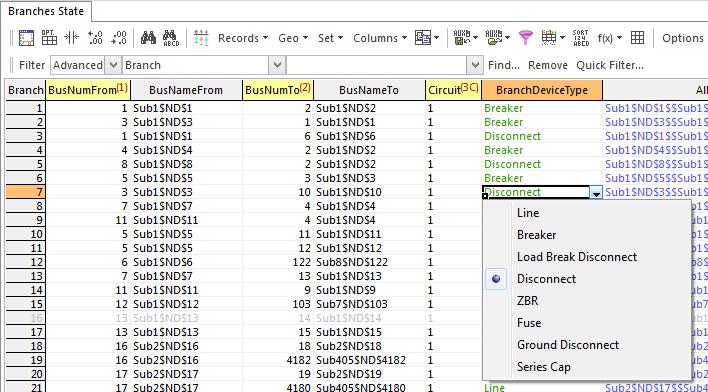
31 BranchDeviceType 31
32 What do Branch Device Types Physically Represent Transformers, Lines, Series Devices We know these Breakers Switching device that can interrupt very high currents such as during a fault Load-Break Disconnect Switching device that can be opened during normal loading conditions, but NOT during a fault Often associated with a capacitor bank Disconnects Switching device can not be opened when under load 32
33 Other BranchDeviceTypes ZBR Wire that connects two points. Might be there so a measurement can be taken Might just be a jumper Ground Disconnect Switching device connects to ground. Some EMS models actually include nodes that represent the ground and then an associated disconnect. Obviously these should NEVER be closed in for purposes of planning activities System operators however are focused on status and worker safety, so it is useful for them to know if a line is actually grounded properly Fuses A fuse 33

34 Example ZBR and Load Break Disconnect ZBR probably there so that one measurement gets flow on line Load Break Disconnect 34
35 Model Detail To the right is a redacted detail of what the topology of a 500 kv bus It s a Breaker and a Half configuration This would be a single bus in a planning case 35
36 Good News: Some data definitions go away Idea of a Line Shunt as compared to a Bus Shunt is unnecessary All shunts are modeled with a connection to a bus Line vs. Bus Shunt just depends on which side of the line breaker it is connected Idea of a Multi-Section Line is unnecessary Software can automatically traverse the topology to determine which branches get isolated by the same set of breakers Open with Breakers option discussed next Concept of a Bypassed series cap goes away There will be a separate breaker to model the bypass 36

37 Capacitor/Reactors all the same Multi-Section Line concept gone Ring Bus Shunts are all the same. LineShunt just means its on the other side of the breakers Bypass Breakers 37
38 Integrated Topology Processing Completely integrate the concept of topology processing inside each software algorithm Each algorithm consolidates in a manner appropriate to it Power flow solve directly on the full-topology model (internally consolidate the power system model as necessary) Contingency analysis (only consolidate as necessary) PV Curve and QV Curve behave differently MW Linearized Tools (ATC, Sensitivity tools, etc.) behave differently 38
39 Full-Topology Power Flow Solution PowerWorld knows when it needs to make a consolidated case and takes care of that User only interacts with the full-topology model Power Flow Solution returns flows on all devices Contingency analysis limit monitoring looks at all devices including switching devices (assuming limits are assigned!) Option to filter bus voltage reporting so only one node inside a Superbus reports as a violation 39

40 MW and Mvar flow arrows on all devices on oneline diagrams 40

41 Table of Breakers showing MW and Mvar flows 41

42 Limit Monitoring in the Power Flow 42
43 PowerWorld Software Features where BranchDeviceTypes Matter Software has many automated features that use the BranchDeviceType Information Full Topology Automatic Coordinated Switched Shunt Control User Interaction features Open Breakers to Isolate and Close Breakers to energize Contingency Analysis Open with Breakers These features will only open the Breakers 43
44 Full Topology Automatic Coordinated Switched Shunt Control PowerWorld automatically detects a group of Switched Shunts that regulate the voltage at the same point By point we mean a group of buses connected by very low impedance branches Don t have to regulate the exact same node, just be connected Shunt will automatically close breakers and load break disconnects in series with shunt to perform shunt control No additional input data: PowerWorld just detects 44

45 Full Topology Automatic Coordinated Switched Shunt Control Example: 4 shunts all regulate Initial solution has regulate voltage inside High/Low Range Change Volt High to

46 Power Flow Solution automatically closes in the breaker Automatically closed in Breaker (would also close in a Load Break Disconnect) 46

47 User Interaction features: Open Breakers to Isolate 47


48 User Interaction features: Open Breakers to Isolate Automatically Finds Breakers Skip over ZBR 48


49 User Interaction features: Close Breakers to Energize Dialog Appears asking you to pick which breakers to close 49

50 Model a Breaker Failure Perform Open with Breakers on a device that is a Breaker PowerWorld assumes that you want to find breakers that surround the breaker Assumption is that the breaker will not open (otherwise you d just open it!) Perform Open with Breakers on this breaker 50
51 Using a Full-Topology Export that includes out-of-service lines Open with breakers always works fine Close Breakers to Energize can be troublesome Out-of-service line may also have disconnects open Close Breakers won t work because the open disconnects 0.0 Mvar are in the way!


52 Yet more options to automatically fix this trouble Use Close Breakers to energize with Options 52
53 Close Normally Closed Disconnects This option will look across normally closed disconnects searching for breakers Option will also look in series past breakers for disconnects Treats a series combination of disconnects with a single breaker as though it is one switching decision 53

54 Close Normally Closed Disconnects Finds the Disconnects too 54
55 Bus table and Superbus PowerWorld treats all nodes as additions to the bus table Represent a point where devices connect Superbus table (user does not create software figures it out) Superbus = group of buses connected by closed switching devices It is similar in concept to an electrical island Islands are added and removed in the software as branches change status Island = group of buses connected by closed branches of any type Subnet table (user does not create software figures out) Subnet = group of buses connected by open or closed switching devices 55
56 Bus table and Superbus Typically as a user you will not interact with either the Superbus or the Subnet table They are available to see Each Superbus and Subnet also chooses primary node This affects features that report only one bus violation inside a Superbus Also possible for the user to bias the choice of the super bus by assigning a priority to the bus object 56

57 Superbus table 57

58 Subnet Table 58
59 Human Interaction Model Navigation Obstacle Can be confusing to navigate full-topology models Tools that graphically show bus-to-bus connections in the model can get very complicated You can get stuck inside all the disconnects and breakers Makes finding more important devices difficult (lines, transformers, generators, loads) PowerWorld s Bus View has features to help 59
60 Planning Case Bus View COULEE Bus: COULEE (40287) Nom kv: Area: NORTHWEST(40) Zone: Central Washington (403) pu KV Deg 0.00 $/MWh MW 22.8 Mvar MVA 37.4 MW Mvar MVA MW 34.0 Mvar MVA MW 77.6 Mvar MVA MW 77.6 Mvar MVA 0.0 MW 0.3 Mvar 0.3 MVA MW 38.1 Mvar MVA MW 36.8 Mvar MVA MW 48.6 Mvar MVA MW 52.5 Mvar MVA MW 52.5 Mvar MVA MW 9.4 Mvar MVA 0.00 MW 0.00 Mvar A A Am ps Am ps A Am ps A A A Am ps Am ps Am ps A Am ps A Am ps A Am ps A CKT1 CHIEF JO pu KV CKT6 COULE R BELL BPA pu KV MS CKT1 HANFORD pu KV MS MS CKT1 SCHULTZ pu KV CKT2 CKT1 COULEE COULEE pu KV CKT1 COULEE COULEE pu KV CKT1 COULEE COULEE pu KV CKT1 COULEE COULEE pu KV Am ps CKT1 COULEE COULEE pu KV CKT1 COULEE COULEE pu KV A Am ps A M VA tap CKT1 COULEES pu KV 60


61 Full Topology Bus View Shows stack of serially connected nodes Bias to show lines, transformer, or series cap prominently If those not available, then biases to show breaker Skip over disconnects Skip over breaker and disconnect to get to transformer 61

62 Consolidated Superbus View Looks like the planning case essentially 62


63 Overview Oneline Visualizations will likely be Substation Based 63
64 EMS Oneline Diagrams Peak Reliability has a lot of custom-built substation topology diagrams Our most recent set from them for testing had 4,494 diagrams Clearly not something that they are going to draw a second time After a short project (about 1 person-month of effort), we built a translation file that describes how the various symbols on their onelines are drawn Areva onelines are all built around user-customized symbols, so we had to translate a few hundred symbols Once Peak Reliability s symbols are translated, PowerWorld can directly read in all 4,494 of these online diagrams Still working on a mechanism to keep this up-to-date They add new kinds of symbols to the diagrams Peak will share these with other companies Have done same work with ISO New England and BPA 64

65 Build Tools to Load Substation Topology Onelines 65
66 Contingency Definitions Bad News In a real-time model these can get very complicated and confusing A Single Line Outage turns into 4 different breakers opening together The breakers necessary to isolate a line change as system topology changes We need a better way to define a contingency (which we have) Good News We can model a breaker failure easily now 66

67 Open with Breakers and Close with Breakers Contingency Actions Open a device using breakers instead of changing the status of the device directly Ensures that accurate modeling of real-time system is achieved Automatically determine Breakers that need to open to isolate an element Breaker failure scenarios can be modeled by applying this action to a breaker Same idea for a Close with Breakers action 67

68 Example Contingency Analysis Explicit Breakers Open Breakers Complex OPENCBS on Line and Bus 68

69 What Actually Occurred Reporting OPENCBS action will report which breakers where actually open Origin of Action = ELEMENT DYNAMIC This means Simulator dynamically figured out what to open What opens will not always be the same If a disconnect is open that is normally closed then the contingency actions that occur are different 69


70 More Complex What Actually Occurred Reporting Special #1, #2, #3 etc. marking in the What Occurred indicates which devices required which breakers to open 70
71 Monitoring of Switching Devices in Contingency Analysis and Power Flow Nothing different than before A breaker, disconnect, line, transformer, and series cap are all the same Any device that has a limit specified is monitored regardless of what is going on inside the solution Software calculates flows on everything Series Caps Disconnect Series Caps Breaker with Limits Line 71

72 Violations shown as normal 72
 Also monitors the highest minimum and lowest maximum voltage inside a")
73 Bus Voltage Limit Monitoring Option (checked by default) will monitor only the primary bus for each super bus Caveat, buses inside a Superbus could have different limits (strange but happens) Also monitors the highest minimum and lowest maximum voltage inside a Superbus 73
74 Tools Is my Line Open? Branch Status Confusion Planning software and bus-branch models Two Fields: Status and Online Status: an explicit field to determine if a device is closed/open (because breakers are not modeled) Online: whether or not a device is energized is affected by the status of branches Real-time models Breaker or disconnect statuses determine the status of other devices No explicit status field for other devices (Generators, Loads, Lines, Transformers, etc.) 74
75 Derived Status: Device Status Confusion Typically, when using a full-topology model, Status = Closed for all non-switching devices (Generators, Loads, Lines, etc.) Hybrid model with only parts of the system modeled with breaker detail can still use Status field of a nonswitching device Actual status of a device is confusing Status of a line is really derived from other information (breaker statuses) Software automatically traverses the topology at the terminals of a device to determine its Derived Status Looks at status of Breakers near terminals Software also has a field Derived Online 75
76 For more details see Simulator Help ocumentation_html/device_derived_status.htm 76

77 Script Command: ExpandBusTopology() This can be used to take a bus and split it up automatically You then have to rearrange all the connections that come into this bus though Was added for professors building fake power systems for research purposes You aren t building fake stuff, so just go get your EMS data 77
78 More already maintained data from the EMS system Over the past 2 years, PowerWorld has worked with Peak Reliability to directly import additional information Contingency Definitions from Areva system Remedial Action Scheme definitions from Areva system Scheduled Outage information from the CROW outage schedules This is all possible because these systems use the same label convention as used in the EMS This is a presentation for another day 78
79 Summary PowerWorld has a lot of experience working with EMS data Hard-learned lessons learned Investment of a huge amount of additional staff time into building parallel data sets won t work It might work for a pilot project but will fail in practice You need to use the already maintained data sets as much as possible Industry s response to asking that additional data sets be maintained is Don t change my data, change your software 79
80 What should the industry do Do NOT build a parallel process maintaining a second full-topology model This is not sustainable Would require an enormous new permanent expense of additional engineering staff Instead: change the starting model Start with a recent EMS system model Comes with already maintained: model, diagrams, contingency definitions, RAS, etc. Discuss with the EMS system folks and ask them to add some more detail EMS software already supports - just add more model info 80
81 Existing EMS model updates EMS engineers already struggle to keep models up to date communicating amongst themselves I can not envision a reliable process that adds to this workload by adding coordination with planning models as well 81
82 What do Planners need to ask of EMS Engineers Add more detail to EMS models. Existing EMS software supports: just add more model info Generator station auxiliary loads Generator step-up transformers Keep the normal status of switching devices up-to-date (breakers, disconnects) This are vital to putting lines, gens, etc back into service Remove artificial device aggregation 2 generators grouped into a single generator in the model Historically this detail was not vital to EMS tools such as SCADA / State Estimation / Contingency Analysis This detail is important for transient stability and voltage stability analysis though 82
83 Generator Station Load In real-time systems, sometimes the generator station load is not modeled explicitly. May not have separate measurements for generator output and station load This will be a problem if trying to do some types of analysis (Transient Stability) Example of where additional detail in planning model may need to be pushed into the real-time model 83
84 Planning Software tools need to be updated Must support full topology Remove artificial device aggregation EMS models do not group together 10 capacitor banks into a single switched shunt Longer-term discussion of more complex equipment DC transmission devices in particular are not consistently modeled across EMS and Planning software tools Use as much already-maintained data from EMS system as possible Model, oneline, contingencies, RAS, etc. 84
85 Envisioned Process Planning engineers already have to integrate future projects into a model They ve done this for decades They will always do this Just switch the starting model to be a recent EMS model export instead Maybe grab this snapshot at an interval The normal status of switching devices matter here (must put that in the EMS model) 85
Modeling of RAS and Relays in Power Flow Contingency Analysis. Jamie Weber
 Modeling of RAS and Relays in Power Flow Contingency Analysis Jamie Weber weber@powerworld.com 217 384 6330 ext. 13 2001 South First Street Champaign, Illinois 61820 +1 (217) 384.6330 support@powerworld.com
PowerWorld Simulator 17 What s New in Simulator. Mark Laufenberg
 PowerWorld Simulator 17 What s New in Simulator Mark Laufenberg lauf@powerworld.com 217 384 6330 ext. 10 2001 South First Street Champaign, Illinois 61820 +1 (217) 384.6330 support@powerworld.com http://www.powerworld.com
Node-Breaker Modeling Representation
 Node-Breaker Modeling Representation On December 6, 2016 NERC hosted a webinar on the Node-Breaker model representation. The majority of off-line planning studies currently use bus-branch models to represent
Introduction to PowerWorld Simulator: Interface and Common Tools
 Introduction to PowerWorld Simulator: Interface and Common Tools I1: The PowerWorld Simulator Case Editor 2001 South First Street Champaign, Illinois 61820 +1 (217) 384.6330 support@powerworld.com http://www.powerworld.com
Record Specification and File Format for Specifying Contingency Definitions and Remedial Actions Schemes
 Record Specification and File Format for Specifying Contingency Definitions and Remedial Actions Schemes Matt Davis matt@powerworld.com 217 384 6330 Ext. 20 2001 South First Street Champaign, Illinois
Specifics of Implementation
 Specifics of Implementation Defining Criteria Filtering ModelCondition ModelFilter Conditional Contingency Actions CriteriaStatus = POSTCHECK ModelExpression (lookup tables) RemedialAction Complexity of
Record Specification and File Format for Specifying Contingency Definitions and Remedial Actions Schemes
 Record Specification and File Format for Specifying Contingency Definitions and Remedial Actions Schemes Date : October 22, 2013 December 6, 2013 January 21, 2015 August 28, 2015 Prepared by : James Weber,
Changes to Difference Case Tool in Simulator 20
 Changes to Difference Case Tool in Simulator 20 Presented by: Jamie Weber, Ph.D. Director of Software Development 2001 South First Street Champaign, Illinois 61820 +1 (217) 384.6330 support@powerworld.com
Multi User Operations Training Simulator. Trainers Workshop Reception
 : Multi User Operations Training Simulator Trainers Workshop Reception July 26, 2012 2001 South First Street Champaign, Illinois 61820 +1 (217) 384.6330 Scott R. Dahman, P.E. scott@powerworld.com http://www.powerworld.com
Small Generator Interconnection System Impact Study Report. Completed For Q0047
 Small Generator Interconnection Completed For Q0047 Proposed Interconnection PacifiCorp s Existing Goshen Rigby 69 kv Line March 7, 2005 1.0 Description of the Generation Facility Q0047 ( Interconnection
Transient Stability Analysis with PowerWorld Simulator
 Transient Stability Analysis with PowerWorld Simulator T14: Large-Scale Simulation Examples 2001 South First Street Champaign, Illinois 61820 +1 (217) 384.6330 support@powerworld.com http://www.powerworld.com
Proposal for Development and Use of Node- Breaker Topology Representations for Offline and Real-time Study Models November 12, 2013
 Proposal for Development and Use of Node- Breaker Topology Representations for Offline and Real-time November 12, 2013 Rationale Background Interconnection wide powerflow and dynamics cases are currently
Dynamic Load Models in PowerWorld Simulator
 Dynamic Load Models in PowerWorld Simulator Jamie Weber (weber@powerworld.com) Director of Software Development 2001 South First Street Champaign, Illinois 61820 +1 (217) 384.6330 support@powerworld.com
Tutorials. Tutorial: Creating a New Case Page 1 of 13
 Tutorial: Creating a New Case Page 1 of 13 This procedure describes how to create a simple power system model using PowerWorld Simulator. This procedure was developed for use with version 13 and later
PowerWorld Simulator Version 20 Auxiliary File Format Description for Specifying Contingency Definitions and Remedial Actions
 PowerWorld Simulator Version 20 Auxiliary File Format Description for Specifying Contingency Definitions and Remedial Actions Date : December 1, 2015 (Simulator Version 19 Release) Last Update : Prepared
PowerWorld Simulator Data Checks
 PowerWorld Simulator Data Checks Jamie Weber, Ph.D. Director of Software Development 2001 South First Street Champaign, Illinois 61820 +1 (217) 384.6330 support@powerworld.com http://www.powerworld.com
What s New in Simulator Version 18
 What s New in Simulator Version 18 PowerWorld Client Conference May 20, 2014 Jamie Weber weber@powerworld.com 217 384 6330 ext 13 2001 South First Street Champaign, Illinois 61820 +1 (217) 384.6330 support@powerworld.com
HIGH LEVEL REQUIREMENTS OF FAST SIMULATION AND MODELLING SUITE OF TOOLS FOR FUTURE SELF-HEALING DISTRIBUTION POWER SYSTEM
 HIGH LEVEL REQUIREMENTS OF FAST SIMULATION AND MODELLING SUITE OF TOOLS FOR FUTURE SELF-HEALING DISTRIBUTION POWER SYSTEM A. Valenti* I Bel ** S. Lee *EDF **EPRI E2I ConEdison France USA USA arnaud.valenti@edf.fr
EMS / DMS. DISTRIBUTION MANAGEMENT SYSTEM- Functional Description
 EMS / DMS DISTRIBUTION MANAGEMENT SYSTEM- Content 1. INTRODUCTION... 4 2. MODES OF INTERACTION WITH THE SCADA SYSTEM... 5 2.1 Simulation Mode... 5 2.2 State Estimation Mode (See functional description
Evolution of Control for the Power Grid
 Evolution of Control for the Power Grid Anjan Bose Washington State University Pullman, WA, USA PaiFest In Honor of Prof. M. A. Pai Urbana-Champaign, IL October 15, 2015 The Past (before 1960s) Hard
Smart Distribution Technology
 Smart Distribution Technology Presentation Agenda Alabama Power Company, A Southern Company Distribution Automation Supervisory Control And Data Acquisition (SCADA) Multiple Address System (MAS) communications
University of California, Santa Cruz Baskin Engineering School Electrical Engineering Department
 Lab-2 Intro, rev2.0, page 1 University of California, Santa Cruz Baskin Engineering School Electrical Engineering Department Laboratory 2 Tutorial Addendum Introduction to POWERWORLD Simulator EE175L Power
ELG4125: System Protection
 ELG4125: System Protection System Protection Any power system is prone to 'faults', (also called short-circuits), which occur mostly as a result of insulation failure and sometimes due to external causes.
A Data Approach to Advanced Distribution Management Systems. L. WILKE, B. WALL POWER Engineers USA
 21, rue d Artois, F-75008 PARIS CIGRE US National Committee http : //www.cigre.org 2017 Grid of the Future Symposium A Data Approach to Advanced Distribution Management Systems L. WILKE, B. WALL POWER
Caroline Marzinzik. CMPLDW Support in PowerWorld Simulator ext. 12
 CMPLDW Support in PowerWorld Simulator Caroline Marzinzik caroline@powerworld.com 217 398 2340 ext. 12 2001 South First Street Champaign, Illinois 61820 +1 (217) 384.6330 support@powerworld.com http://www.powerworld.com
Revised Generation Interconnection Impact Study Report. For. Queue Position 31 ( Interconnection Customer )
") Revised Generation Interconnection Impact Study Report For Queue Position 31 ( Interconnection Customer ) September 22, 2004 1 Generation Interconnection System Impact Study Report I. Revision of Original
Revised Generation Interconnection Impact Study Report For Queue Position 31 ( Interconnection Customer ) September 22, 2004 1 Generation Interconnection System Impact Study Report I. Revision of Original
Redundant Bus Protection Using High-Impedance Differential Relays. Josh LaBlanc
 Redundant Bus Protection Using High-Impedance Differential Relays Josh LaBlanc Purpose Discuss the configuration of the bus under study, and touch on the needs for redundant protection on the bus. Briefly
Using PMU Data to Increase Situational Awareness
 Using PMU Data to Increase Situational Awareness Tom Overbye Fox Family Professor of Electrical and Computer Engineering University of Illinois at Urbana-Champaign December 2010 PSERC Webinar PSERC Project
Approval...6. Current Revision...7. Introduction... 8 About PJM Manuals... 8 About This Manual... 8 Using This Manual...9
 PJM Manual 07: PJM Protection Standards Revision: 3 Effective Date: May 24, 2018 Prepared by System Planning Division Transmission Planning Department PJM 2018 Table of Contents Table of Contents Approval...6
Chapter 2 State Estimation and Visualization
 Chapter 2 State Estimation and Visualization One obvious application of GPS-synchronized measurements is the dynamic monitoring of the operating conditions of the system or the dynamic state estimation
What s New in Simulator Version 20
 What s New in Simulator Version 20 Prepared by Caroline Marzinzik caroline@powerworld.com 217 384 6330 Ext. 12 2001 South First Street Champaign, Illinois 61820 +1 (217) 384.6330 What s New in Version
Feasibility Study on Load Flow and Short Circuit Project
 Feasibility Study on Load Flow and Short Circuit Project 101813-01 Prepared by: Transmission Planning Department Cleco Corporation, Inc. 2180 St. Landry Hwy P.O. Box 70 St. Landry, LA 71367 Final November
Using WECC Composite Load Model and PowerWorld Time Step Simulation Tool. Eleanor Ewry
 Using WECC Composite Load Model and PowerWorld Time Step Simulation Tool Eleanor Ewry Engineer October 21, 2014 Overview Introduction to Composite Load Model Introduction to Time Step Simulation (TSS)
Effect of Topology Control on System Reliability: TVA Test Case
 Effect of Topology Control on System Reliability: TVA Test Case Professor Kory W. Hedman School of Electrical, Computer, and Energy Engineering Arizona State University Tempe, AZ 85287-5706 CIGRE, October
Maximizing protection coordination with self-healing technology
 Supersedes December 2011 Daniel P. Roth, Distribution Automation Technical Manager, Eaton s Cooper Power Systems Abstract Much of the Smart Grid initiative includes the installation of new recloser and
Design and Analysis of Algorithms Prof. Madhavan Mukund Chennai Mathematical Institute. Week 02 Module 06 Lecture - 14 Merge Sort: Analysis
 Design and Analysis of Algorithms Prof. Madhavan Mukund Chennai Mathematical Institute Week 02 Module 06 Lecture - 14 Merge Sort: Analysis So, we have seen how to use a divide and conquer strategy, we
Real-time Power System Operation. Energy Management Systems. Introduction
 1 Real-time Power System Operation Energy Management Systems Introduction The time frame for Power Systems Operation varies from a few seconds to a week. To assist with the operation of the system, modern
Dispatcher Training Simulator (DTS) JOB AIDE
 JOB AIDE") APPLICABILITY: System Operators or anyone operating the system via Peak s GE- Alstom. I. Purpose To provide System Operators a job aid on using the DTS, particularly within the restoration drill. II. Introduction
APPLICABILITY: System Operators or anyone operating the system via Peak s GE- Alstom. I. Purpose To provide System Operators a job aid on using the DTS, particularly within the restoration drill. II. Introduction
This webinar brought to you by the Relion product family
 This webinar brought to you by the Relion product family Relion. Thinking beyond the box. Designed to seamlessly consolidate functions, Relion relays are smarter, more flexible and more adaptable. Easy
Exercise 2. Single Bus Scheme EXERCISE OBJECTIVE DISCUSSION OUTLINE. The single bus scheme DISCUSSION
 Exercise 2 Single Bus Scheme EXERCISE OBJECTIVE When you have completed this exercise, you will be familiar with electric power substations using the single bus scheme with bus section circuit breakers.
Road Map to Grid Modernization
 Road Map to Grid Modernization APIC, University of Alberta May 5 th, 2016 Presenter: Chris Chapelsky, MSc., P.Eng. Operations 1 Engineer About EPCOR Water & Power Transmission & Distribution in Edmonton
DRAFT Reliability Guideline: Modeling Distributed Energy Resources in Dynamic Load Models
 DRAFT Reliability Guideline: Modeling Distributed Energy Resources in Dynamic Load Models Problem Statement With the proliferation of distributed energy resources (DER), Transmission Planners must adapt
What s New in Simulator Version 20
 What s New in Simulator Version 20 Prepared by Caroline Marzinzik caroline@powerworld.com 217 384 6330 Ext. 12 2001 South First Street Champaign, Illinois 61820 +1 (217) 384.6330 What s New in Version
Karl Iliev, San Diego Gas & Electric Company
 INTEGRATING DER THROUGH DISTRIBUTION SYNCROPHASORS Karl Iliev, San Diego Gas & Electric Company 2002 San Diego Gas and Electric Co. and Southern California Gas Company. All copyright and trademark rights
The Different Types of UPS Systems
 The Different Types of UPS Systems White Paper # 1 Revision 4 Executive Summary There is much confusion in the marketplace about the different types of UPS systems and their characteristics. Each of these
Bus Protection Application Challenges
 Bus Protection Application Challenges KN Dinesh Babu - Megger JC Theron, Lubomir Sevov GE Grid Solutions 2017 Texas A&M Protective Relay Conference Content Introduction Application Challenges Increase
POWER WORLD LAB MANUAL
 POWER WORLD LAB MANUAL Power world is a great powerful tool for solving power flows. Solving a power system is a little different from circuit analysis. Instead of being given voltages at certain nodes
IntelliGrid. Don Von Dollen IntelliGrid Program Manager (650)
") IntelliGrid Don Von Dollen IntelliGrid Program Manager dvondoll@epri.com www.epri-intelligrid.com (650) 855-2679 Background EPRI s IntelliGrid Program Mission: To accelerate the transformation of the power
IntelliGrid Don Von Dollen IntelliGrid Program Manager dvondoll@epri.com www.epri-intelligrid.com (650) 855-2679 Background EPRI s IntelliGrid Program Mission: To accelerate the transformation of the power
XP: Backup Your Important Files for Safety
 XP: Backup Your Important Files for Safety X 380 / 1 Protect Your Personal Files Against Accidental Loss with XP s Backup Wizard Your computer contains a great many important files, but when it comes to
Generator Interconnection Impact Study Report Pamlico County, NC 200 MW Wind Farm Queue #281
 Generator Interconnection Impact Study Report Pamlico County, NC 200 MW Wind Farm Queue #281 June 6, 2012, Inc. PURPOSE The purpose of this impact study is to assess the impacts of a wind farm interconnection
Steady-State Power System Security Analysis with PowerWorld Simulator
 Steady-State Power System Security Analysis with PowerWorld Simulator 2001 South First Street Champaign, Illinois 61820 +1 (217) 384.6330 support@powerworld.com http://www.powerworld.com Available Transfer
Awareness of the Situation
 17/11/21 Situational Awareness UPDEA - Workshop Awareness of the Situation 25,623 Alarms in 8 ours 53 Alarms / min (average) 8% Are consequential Things 1 to keep in mind during a disturbance - Analog
1 Description of Methodology for Volt / Var Optimization
 Methodology for Volt / Var Optimization on a Substation Basis May 13th, 2011 Version 1.7 1 Methodology for Volt / Var Optimization (VVO) on a Substation Basis This use case discusses how the utility will
A guide on PowerWorld Simulator ver. 12.0
 A guide on PowerWorld Simulator ver. 12.0 This tutorial has been developed to aid the undergraduate and graduate students at the University of Cyprus to learn the basic features of PowerWorld. It is not
Data Driving the Smart Grid
 Data Driving the Smart Grid Network Model Management for Distribution Operations Eric J. Charette, P.E. Annual GITA Conference - Pacific Northwest Chapter April 24th - 25th, 2017 Future of Flight Aviation
Generation Interconnection Feasibility Study Report
 Project #169 Generation Interconnection Feasibility Study Report 7/2/2014 Regional Electric Transmission Planning TABLE OF CONTENTS Executive Summary... 3 Generator and Interconnection Data... 5 Study
N-1-1 Reactive Upgrades
 N-1-1 Reactive Upgrades Previous Analysis Discussed at November 2011 TEAC Voltage collapse for multiple 500 kv N-1-1 contingency pairs A number of reactive upgrade locations evaluated to determine a optimal
LAB1 INTRODUCTION TO PSS/E EE461: POWER SYSTEMS COLORADO STATE UNIVERSITY
 LAB1 INTRODUCTION TO PSS/E EE461: POWER SYSTEMS COLORADO STATE UNIVERSITY PURPOSE: The purpose of this lab is to introduce PSS/E. This lab will introduce the following aspects of PSS/E: Introduction to
ASPEN Software - Introduction
 ASPEN Software - Introduction ASPEN is a very user-friendly software package that is capable of doing load-flow and shortcircuit studies, as well as relay application and coordination. Its simple graphical
Auto-Check Circuit Breaker Interrupting Capabilities
 Auto-Check Circuit Breaker Interrupting Capabilities Thanh C. Nguyen and Sherman Chan ASPEN, Inc. Ron Bailey and Thanh Nguyen Dominion Virginia Power Paper published in IEEE Computer Applications in Power,
ABB static var compensator stabilizes Namibian grid voltage
 Power ABB static var compensator stabilizes Namibian grid voltage factor! Rolf Grünbaum, Mikael Halonen, Staffan Rudin The spectacular dune landscapes of Namibia are a key factor in the country s booming
The Future of Real-Time Energy Management Systems For Transmission System Operations
 San Francisco Chapter The Institute of Electrical and Electronic Engineers Power Engineering Society The Future of Real-Time Energy Management Systems For Transmission System Operations John Sell, EleQuant,
OPF Automation Examples
 OPF Automation Examples 2001 South First Street Champaign, Illinois 61820 +1 (217) 384.6330 support@powerworld.com http://www.powerworld.com OPF Automation Examples Standardize settings with Auxiliary
RouteOp. Step 1: Make sure requirements are met.
 RouteOp If you are just getting started please note that the features are not enabled until your first call. You will receive a welcome email to get the ball rolling and will be hearing from your implementation
ASPEN Software - Introduction
 ASPEN Software - Introduction ASPEN is a very user-friendly software package that is capable of doing load-flow and shortcircuit studies, as well as relay application and coordination. Its simple graphical
Christian PAYERL, Poznan, 20 th May, 2009 ABB FACTS Grid connection of Wind Farms. ABB Group May 22, 2009 Slide 1
 Christian PAYERL, Poznan, 20 th May, 2009 ABB FACTS Grid connection of Wind Farms May 22, 2009 Slide 1 FACTS Applications Flexible AC Transmission Systems May 22, 2009 Slide 4 System Studies - Grid Codes
6.001 Notes: Section 8.1
 6.001 Notes: Section 8.1 Slide 8.1.1 In this lecture we are going to introduce a new data type, specifically to deal with symbols. This may sound a bit odd, but if you step back, you may realize that everything
CS 162 Operating Systems and Systems Programming Professor: Anthony D. Joseph Spring Lecture 20: Networks and Distributed Systems
 S 162 Operating Systems and Systems Programming Professor: Anthony D. Joseph Spring 2003 Lecture 20: Networks and Distributed Systems 20.0 Main Points Motivation for distributed vs. centralized systems
DATABASE TRANSACTIONS. CS121: Relational Databases Fall 2017 Lecture 25
 DATABASE TRANSACTIONS CS121: Relational Databases Fall 2017 Lecture 25 Database Transactions 2 Many situations where a sequence of database operations must be treated as a single unit A combination of
Tutorial 8: Actual Market Data
 Tutorial 8: Actual Market Data This tutorial looks at how to model a portion of the actual New Zealand electricity market, detailing where to locate the source files and how to extract the necessary modelling
NERC Event Analysis Update Webinar. Hassan Hamdar Chair, Event Analysis Subcommittee October 20, 2016
 NERC Event Analysis Update Webinar Hassan Hamdar Chair, Event Analysis Subcommittee October 20, 2016 Webinar Agenda ERO Event Analysis Process Update Lesson Learned Presentation from Entity ERO Lessons
Siemens FuseSaver New half-cycle circuit breaker for rural smart grids to minimize operating costs of feeder and spur lines
 Siemens FuseSaver New half-cycle circuit breaker for rural smart grids to minimize operating costs of feeder and spur lines Authors: Dr. Brett Watson, Siemens Ltd., PO Box 4833, Loganholme, QLD 4129, Australia
Generation, Transmission, and End User Facilities
 Procedures for Interconnection of Generation, Transmission, and End User To the Grand River Dam Authority Transmission System Table of Contents GRDA/SPP Interaction... 3 Standards... 3 Generation... 3
ONLINE CLOSED-LOOP OPTIMIZATION OF DISTRIBUTION NETWORKS
 ONLINE CLOSED-LOOP OPTIMIZATION OF DISTRIBUTION NETWORKS Werner FEILHAUER Michael HEINE Andreas SCHMIDT PSI AG, EE DE PSI AG, EE DE PSI AG, EE - DE wfeilhauer@psi.de mheine@psi.de aschmidt@psi.de ABSTRACT
CS 162 Operating Systems and Systems Programming Professor: Anthony D. Joseph Spring Lecture 19: Networks and Distributed Systems
 S 162 Operating Systems and Systems Programming Professor: Anthony D. Joseph Spring 2004 Lecture 19: Networks and Distributed Systems 19.0 Main Points Motivation for distributed vs. centralized systems
2009 SPP TransCanada Pipeline Study Report
 2009 SPP TransCanada Pipeline Study Report SPP Engineering Department, Planning Section PUBLISHED: 7/9/2009 LATEST REVISION: 7/9/2009 Copyright 2009 by Southwest Power Pool, Inc. All rights reserved. Table
DECK All-In-One Enclosure. Quick Installation Guide for Field Installers
 DECK All-In-One Enclosure Quick Installation Guide for Field Installers 1 Contents Legal Statement... 2 Preliminary Considerations... 2 Required Installation Tools and Materials... 2 Networking Information...
MISO Online Dynamic Security Assessment(DSA) Raja Thappetaobula Senior Advisor MISO
 Raja Thappetaobula Senior Advisor MISO") 1 MISO Online Dynamic Security Assessment(DSA) Raja Thappetaobula Senior Advisor MISO 2 MISO Overview MISO is an independent, non-profit, memberbased organization committed to reliability. We serve as
1 MISO Online Dynamic Security Assessment(DSA) Raja Thappetaobula Senior Advisor MISO 2 MISO Overview MISO is an independent, non-profit, memberbased organization committed to reliability. We serve as
XXXX. Bear Creek Hydro Generation Project. Interconnection Facilities Study
 XXXX Bear Creek Hydro Generation Project Interconnection Facilities Study Report No. SPA 2005-33 August 2005 System Planning (Lower Mainland & Vancouver Island) British Columbia Transmission Corporation
Visualization Software for Wide-Area Situational Awareness. Power Affiliates Program. May 20, 2011
 Visualization Software for Wide-rea Situational wareness Power ffiliates Program May 20, 2011 2001 South First Street Champaign, Illinois 61820 +1 (217) 384.6330 Mark Laufenberg, Ph.D. lauf@powerworld.com
Solutions for transmission network management
 EM SG SOLutions Solutions for transmission network management Energy Management Smart Grid Solutions Solutions for Transmission Network Management Overview Operator Training Simulator Blackout Prevention
Lessons Learned Implementing an IEC based Microgrid Power- Management System. K.A. GRAY, J.J. MRAZ* POWER Engineers, Inc.
 21, rue d Artois, F-75008 PARIS CIGRE US National Committee http : //www.cigre.org 2015 Grid of the Future Symposium Lessons Learned Implementing an IEC 61850-based Microgrid Power- Management System K.A.
Sub Regional RTEP Committee Mid-Atlantic First Energy MAAC
 Sub Regional RTEP Committee Mid-Atlantic First Energy MAAC September 21, 2018 Penelec Transmission Zone Need Number: PN-2018-001 Consider upgrading transmission line equipment (switches, conductor, splices,
Peak V&R R-T Voltage Security Assessment (VSA) Tool Validation 9/9/2014, JSIS. Hongming Zhang EMS Applications Manager, PEAK RC
 Tool Validation 9/9/2014, JSIS. Hongming Zhang EMS Applications Manager, PEAK RC") Peak V&R R-T Voltage Security Assessment (VSA) Tool Validation 9/9/2014, JSIS Hongming Zhang EMS Applications Manager, PEAK RC Agenda Peak-ROSE project deliverables. ROSE VSA scenarios validation strategy.
Peak V&R R-T Voltage Security Assessment (VSA) Tool Validation 9/9/2014, JSIS Hongming Zhang EMS Applications Manager, PEAK RC Agenda Peak-ROSE project deliverables. ROSE VSA scenarios validation strategy.
Network Configuration Document Selection for New Substations Framework
 Network Configuration Document Selection for New Substations Current version: 20/06/2018 EXTERNAL USE Page 1 of 14 Table of contents 1. Introduction... 3 1.1 Purpose... 3 1.2 Scope... 3 1.3 References...
ISO New England Data Modeling Requirements
 A U G U S T 1 5, 2 0 1 6 B O S T O N, M A ISO New England Data Modeling Requirements Renew Northeast Meeting Al McBride D I R E C T O R, T R A N S M I S S I O N S T R A T E G Y & S E R V I C E S Agenda
RTDMS CAISO TRAINING SESSION
 Consortium for Electric Reliability Technology Solutions Real-Time Dynamics Monitoring System (RTDMS ) RTDMS CAISO TRAINING SESSION January 31, 2006 Manu Parashar & Jim Dyer Electric Power Group (EPG)
It is the job of the protection system equipment to recognize and remove the fault.
 Protection 1 (read section 13.0 of text) 1.0 Introduction Faults do not occur that frequently 1/year/100 miles of transmission is typical. Distribution systems may see more than this. However, when they
Power Quality of Commercial Buildings - Advanced
 Buildings - Advanced Hartford Steam Boiler One State Street P.O. Box 5024 Hartford, CT 06102-5024 Tel: (800) 472-1866 www.munichre.com/hsb May 2017 Background Power quality is a general term used to describe
ECE 528 Understanding Power Quality. Paul Ortmann (voice) Lecture 23
 Lecture 23") ECE 528 Understanding Power Quality http://www.ece.uidaho.edu/ee/power/ece528/ Paul Ortmann portmann@uidaho.edu 208-733-7972 (voice) Lecture 23 1 Today: An introduction to industrial controls Basic hard-wired
ECE 528 Understanding Power Quality http://www.ece.uidaho.edu/ee/power/ece528/ Paul Ortmann portmann@uidaho.edu 208-733-7972 (voice) Lecture 23 1 Today: An introduction to industrial controls Basic hard-wired
Programming and Data Structures Prof. N.S. Narayanaswamy Department of Computer Science and Engineering Indian Institute of Technology, Madras
 Programming and Data Structures Prof. N.S. Narayanaswamy Department of Computer Science and Engineering Indian Institute of Technology, Madras Lecture - 13 Merging using Queue ADT and Queue types In the
BC HYDRO REAL TIME OPERATIONS SYSTEM OPERATING ORDER 7T - 50
 BC HYDRO REAL TIME OPERATIONS SYSTEM OPERATING ORDER 7T - 50 VOLTAGE STABILITY OPERATING LIMITS AND PROCEDURES FOR USING THE REAL TIME VOLTAGE STABILITY APPLICATION (RTVSA) Supercedes 7T-50 dated 02 May
Automated Analysis of Digital Relay Data Based on Expert System
 Automated Analysis of Digital Relay Data Based on Expert System X. Luo, Student Member, IEEE, and M. Kezunovic, Fellow, IEEE Abstract Modern digital protective relays generate various files and reports
PG&E Transmission Interconnection Handbook
 Table of Contents TABLE OF CONTENTS... 1 UPDATE HISTORY... UP-1 INTRODUCTION... IN-1 I-1. PURPOSE... IN-1 I-2. INTRODUCTORY DEFINITIONS... IN-1 I-3. HANDBOOK APPLICABILITY... IN-2 I-3.1. New Load, New
Sacramen Sacr t amen o t Municipal Utility Dis t Dis rict t SMUD May Ma 10,
 Sacramento Municipal Utility District SMUD May 10, 2010 1 SMUD Facts and Figures 900 Sq. Miles Service Area 585,500 Customers 1.4 million Area Population 10 Bulk Substations 473 Miles of Transmission Lines
Laboratory Exercise 2. Power Distribution w/autocad Electrical
 Laboratory Exercise 2 Power Distribution w/autocad Electrical Procedure 1. Use the One Line and Three Line Example Drawings to create two drawings with at least 20 one-line elements and two three-line
Load Flow Analysis. I Objectives
 EE342 Electrical Power Lab Experiment PS3 Load Flow Analysis I Objectives To demonstrate load flow concepts. To study system performance under different operating conditions. To experience the real feel
PRC Coordination of Protection Systems for Performance During Faults
 PRC-027-1 Coordination of Protection Systems for Performance During Faults A. Introduction 1. Title: Coordination of Protection Systems for Performance During Faults 2. Number: PRC-027-1 3. Purpose: To
Requests for Clarifications And Responses Order No. 754 Data Request The Study of Single Point of Failure
 Requests for Clarifications And Responses Order No. 754 Data Request The Study of Single Point of Failure Revised: July 12, 2013 Introduction The following information includes requests for clarification
INTERCONNECTION FACILITIES STUDY REPORT
 Interconnection Request No. TI-08-0312 INTERCONNECTION FACILITIES STUDY REPORT Prepared by Tri-State Generation and Transmission Association, Inc. 1 of 7 DISCLAIMER OF WARRANTIES AND LIMITATION OF LIABILITIES