User Manual Gateway component for EtherNet/IP
|
|
|
- Oswin Day
- 6 years ago
- Views:
Transcription


1 User Manual Gateway component for EtherNet/IP PR /7/2016
2 Table of Contents KUNBUS GmbH Table of Contents 1 General Information Disclaimer Notes Regarding this User Manual Validity Limitation of Liability Customer Service Safe Use User Symbols Overview Functionality Control Elements Status LEDs Installation Preparations for Trouble-free Operation Requirements Connecting Gateway Components Installing a Gateway in the Control Cabinet Connecting a Power Supply Connecting a Gateway to the Fieldbus Configuration Supported Size of the Process Data Address Assignment Ethernet/IP Configuration Configuration of Modbus TCP Technical Data Technical Data ii Gateway component for EtherNet_IP
3 1 General Information 1.1 Disclaimer 2015 KUNBUS GmbH, Denkendorf (Germany) The contents of this user manual have been prepared by KUNBUS GmbH with the utmost care. Due to technical development, KUNBUS GmbH reserves the right to change or replace the contents of this user manual without prior notice. You can always obtain the latest version of the user manual at our homepage: KUNBUS GmbH shall be liable exclusively to the extent specified in General Terms and Conditions ( The contents published in this user manual are protected by copyright. Any reproduction or use for the in-house requirements of the user is permitted. Reproduction or use for other purposes is not permitted without the express, written consent of KUNBUS GmbH. Contraventions shall result in compensation for damages. Trademark protection KUNBUS is a registered trademark of KUNBUS GmbH Windows and Microsoft are registered trademarks of Microsoft Corp. KUNBUS GmbH Heerweg 15 c Denkendorf Germany General Information Gateway component for EtherNet_IP 3 / 25
4 1.2 Notes Regarding this User Manual This user manual provides important technical information that can enable you as a user to integrate the Gateways into your applications and systems efficiently, safely and conveniently. It is intended for trained, qualified personnel, whose sound knowledge in the field of electronic circuits and expertise in EtherNet/IP TM is assumed. As an integral part of the module, the information provided here should be kept and made available to the user. General Information 1.3 Validity This document describes the application of the KUNBUS Gateway with the product number: PR100066, release Limitation of Liability Warranty and liability claims will lapse if: the product has been used incorrectly, damage is due to non-observance of the operating manual, damage is caused by inadequately qualified personnel, damage is caused by technical modification to the product (e.g. soldering). 1.5 Customer Service If you have any questions or suggestions concerning this product, please do not hesitate to contact us: KUNBUS GmbH Heerweg 15 C Denkendorf +49 (0) support@kunbus.de Gateway component for EtherNet_IP 4 / 25
5 2 Safe Use 2.1 User The Gateway may only be assembled, installed and put into operation by trained, qualified personnel. Before assembly, it is absolutely essential that this documentation has been read carefully and understood. Expertise in the following fields is assumed: electronic circuits, basic knowledge of EtherNet/IP, work in electrostatic protected areas, locally applicable rules and regulations for occupational safety. Safe Use DANGER 2.2 Symbols The symbols used have the following meaning: Danger Always observe this information! There is a safety hazard that can lead to serious injuries and death. CAUTION Caution There is a safety hazard that can result in minor injuries and material damage. NOTICE Note There is a safety hazard that can result in material damage. Gateway component for EtherNet_IP 5 / 25


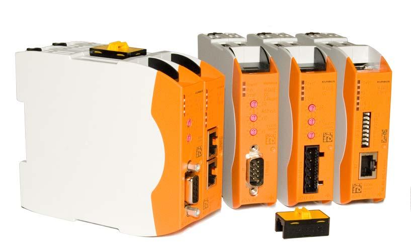
6 3 Overview 3.1 Functionality The KUNBUS Gateway is a protocol converter. It allows communication between networks with different protocols. Overview Illustration 1: Functionality A Gateway consists of 2 gateway components that master one specific protocol each. You can combine these gateway components as you wish. This design offers you a high degree of flexibility, since you can exchange the individual gateway components at any time. The following gateway components are currently available as slaves: CANopen CC-Link DeviceNet EtherCAT EtherNet/IP Modbus RTU Modbus TCP POWERLINK PROFIBUS PROFINET Sercos III Gateway component for EtherNet_IP 6 / 25
7 Features This gateway component enables communication with Ethernet/IP and Modbus TCP. It supports the following functions: RPI Minimal Requested Packet Interval: 1 ms ACD (Address Conflict Detection) DLR You can use the gateway component in a Device Level Ring. Overview Gateway component for EtherNet_IP 7 / 25
8 3.2 Control Elements Front view Overview Illustration 2: Front view 1 Status LEDs 2 Coding switch 8-pin DIP switch for setting the IP address. 3 Fieldbus connection RJ45 socket for the connection to the fieldbus (2 sockets in all, s. figure top view) Gateway component for EtherNet_IP 8 / 25
9 Top Overview Illustration 3: Top 1 Fieldbus connection RJ45 socket for connection to the fieldbus (2 pcs, see figure front view). 2 Interconnect ports for interconnecting the gateway components. 3 Locking clamps for securely attaching the gateway component to the DIN rail. Gateway component for EtherNet_IP 9 / 25
10 Bottom Overview 1 2 Illustration 4: Bottom 1 Mains connection with 24 V power supply 2 Locking clamps for securely attaching the gateway component to the DIN rail. Gateway component for EtherNet_IP 10 / 25
11 3.3 Status LEDs The signals of the status LEDs for EtherNet/IP have the following meaning: Overview LED designation Signal Meaning Power off Gateway component not running blinks, green on, green Initialization phase not yet completed Operational flashes, red Correctable error (e.g. second gateway component missing) on, red MS off No power supply on, green blinks, green on, red Serious error/defect in the gateway Gateway component operational Configuration not completed Unrecoverable error flashes, red Configuration error flashes red and green Self-test NS off Gateway component is switched off or has no IP address blinks, green on, green IP address set but no CIP connection has been established yet Connection is established flashes, red Connection interrupted (e.g. due to timeout) on, red L/A off No connection green blinks, green Set IP address is already being used by another network subscriber Connection to another device. No data exchange takes place. Connection established. Data exchange takes place. Gateway component for EtherNet_IP 11 / 25
12 4 Installation 4.1 Preparations for Trouble-free Operation In the following section we have compiled some general information for you that is important for trouble-free operation. If you are already acquainted with this topic, you can skip to the next section. There, you will learn about which conditions are necessary for installing the gateway. Installation Cable routing Route your cables separately in cable groups. This will protect your gateway from any unintended electromagnetic interferences. The following groups should be routed separately from each other: Group A B C Line Data and power supply lines for: DC voltage below 60 V AC voltage below 25 V Data and power supply lines for: DC voltage between 60 V and 400 V AC voltage between 25 and 400 V Power supply lines above 400 V You can route cables of the same group together in cable ducts or bundles. Cables of group A and B: Route the groups in separate bundles or in cable ducts at a minimum distance of 10 cm from each other. Cables of group C Route the groups in separate bundles or in cable ducts at a minimum distance of 50 cm from the other groups. Gateway component for EtherNet_IP 12 / 25
13 Shielding Shield your cables. This will reduce any unintended electromagnetic interferences. Potential equalization Potential differences occur when devices are connected to different earths. These potential differences cause malfunctions. To prevent malfunctions, you have to route an equipotential equalization conductor. When doing so, bear in mind the following points: Select an equipotential equalization conductor with low impedance. Select the following as a reference value for the cross-section of the potential equalization cable: 16 mm 2 for potential equalization cables of up to 200 m in length 25 mm 2 for potential equalization cables of more than 200 m in length Use potential equalization cables made of copper or galvanized steel. Connect potential equalization cables extensively with the earth rail. The smallest surfaces possible should be sandwiched between potential equalization cables and signal cables. If the devices of the control system are connected by shielded signal cables that are earthed on both sides, the impedance must be 10% of the shielding impedance. Installation Gateway component for EtherNet_IP 13 / 25
14 NOTICE 4.2 Requirements The Gateway was designed for use in a control cabinet. ü The protection class of the control cabinet must be equivalent to at least IP54. ü For installation in the control cabinet you need a DIN rail 35 x 7.5 mm (EN50022). Install the DIN rail horizontally in the control cabinet according to the manufacturers' specifications. When doing so, make sure that the Gateway is at a sufficient distance from other devices. Your gateway could be damaged if temperatures are too high. èmake sure that the ambient temperature in the control cabinet is less than 60 C. èkeep the ventilation slots unobstructed. These must not be covered by cables etc. èmaintain sufficient distance from other devices. Installation Illustration 5: Distances for installation Connect each gateway component individually to functional earth. When doing so, make sure that the power supplies of both gateway components have the same ground. ð Your control cabinet now meets all requirements for installing the gateway. Gateway component for EtherNet_IP 14 / 25
15 4.3 Connecting Gateway Components In order to attain a fully functional gateway, you have to interconnect both gateway components. Connect an interconnect port to each gateway component using the plug-in jumper provided. Installation NOTICE Illustration 6: Connecting gateway components ð You can now install the gateway in the control cabinet. Only ever interconnect 2 gateway components. If you connect additional components, severe defects could result on all devices. Gateway component for EtherNet_IP 15 / 25
16 4.4 Installing a Gateway in the Control Cabinet Hold the raster element of the gateway on the DIN rail. Press down the locking elements towards the gateway. Make sure that the gateway is firmly attached to the DIN rail. Installation Gateway component for EtherNet_IP 16 / 25
17 4.5 Connecting a Power Supply To connect the gateway component to the power supply, you need a spring-loaded terminal (e.g. Metz-Connect SP995xxVBNC). You have to connect each gateway component separately to a power supply. Never interconnect functional earth and GND, otherwise the galvanic isolation between gateway GND and fieldbus ground will be removed. Instead, connect the functional earth with low impedance to the potential equalization. You can then dispense with this connection if the shield of the fieldbus cable is connected to the potential equalization with lower impedance when entering the control cabinet. Installation NOTICE Connect each of the two gateway components to its own power supply èensure in particular that no potential differences occur between the GND pins (2). Pin assignment: Pin Assignment 1 24 V for module supply 2 GND 3 Do not connect! 4 Functional earth NOTICE Do not connect GND to PE This connection could cause unintended malfunctions. Gateway component for EtherNet_IP 17 / 25
18 4.6 Connecting a Gateway to the Fieldbus To connect the gateway component to EtherNet/IP, you need Two RJ45 connectors. The pin assignment complies with the Ethernet standard. Installation Gateway component for EtherNet_IP 18 / 25
19 5 Configuration 5.1 Supported Size of the Process Data The gateway component for EtherNet/IP supports process data of a length up to 480 bytes. Configuration Type Direction Assembly Instance Size Exclusive Owner Output (master -> slave) 100 up to 480 bytes Input (slave -> master) 150 up to 480 bytes Input Only Output (master -> slave) bytes Input (slave -> master) 150 up to 480 bytes Listen Only Output (master -> slave) bytes Input (slave -> master) 150 up to 480 bytes NOTICE Bear in mind that the maximum length of the process data is always determined by the fieldbus with the shorter data length. Example: Ethernet/IP supports 480 bytes per direction. PROFIBUS supports 244 bytes per direction. In conjunction with Ethernet/IP / PROFIBUS this means that 244 bytes are transmitted and updated cyclically. Gateway component for EtherNet_IP 19 / 25
20 Assigning IP Address manually: Receiving IP Address from the DHCP Server Setting IP Address using the Master Software 5.2 Address Assignment Setting IP Address With the 8-pin address switch you can set the IP address of the Gateways. You can set values in binary format between Set any address between ð The gateway component uses the address X with the net mask and gateway Open the website Log on: Logon data for the initial logon : User: Admin Password: 1701 Click on the "Change Configuration" button Set the IP address required Confirm your entry by pressing the "Apply" button Set all address switches to "0" Restart the gateway component by switching this off and then on again. ð The set IP address is now used. Set the value "255" (all switches in the direction of the numbers) to activate the DHCP mode. ð Assign the IP address automatically from the DHCP server. Set the value "0" (all switches to "Off") ð The gateway component uses the IP address that was last set using the software. You can change this IP address at any time via the EtherNet/IPprotocol or website. Restart the gateway component by switching this off and then on again. ð The set IP address is now used. Configuration Gateway component for EtherNet_IP 20 / 25
21 5.3 Ethernet/IP Configuration Standard Objects The following objects are available to you for addressing the process data: Identity Object, Class Code: 01 Hex Message Router, Class Code: 02 Hex Assembly Object, Class Code: 04 Hex Connection Manager Object, Class Code: 06 Hex TCP/IP Interface Object, Class Code: F5 Hex Ethernet Link Object, Class Code: F6 hex Device Level Ring, Class Code: 47 Hex Quality of Service, Class Code: 48 Hex These objects comply with the ODVA standard. You can find further information in the specifications for EtherNet/IP. You can find details about the implemented attributes from the EDS file provided. Configuration Fieldbus Input Data, Class Code: A0 hex Fieldbus Output Data, Class Code: A1 hex Device Specific Objects The following objects are device specific. You can use these to access the input and output data acyclically. Fieldbus Input Data, Class Code: A0 Hex Fieldbus Output Data, Class Code: A1 Hex You can use this object to read data that was sent from the gateway component to the EtherNet/IP-Master. This data originates from the Master of the other gateway components. You can use this object to write data that was sent from the EtherNet/ IP-Master to the gateway component. This data is copied to the input data area of the other gateway component. The Master of the other gateway component can read this data there. Gateway component for EtherNet_IP 21 / 25
22 5.4 Configuration of Modbus TCP You can also use these gateway components as a protocol converter for Modbus TCP. Functions The following Modbus functions are implemented: Configuration Function code 0x01 0x02 0x05 0x0f 0x03 0x04 0x06 0x10 0x16 0x17 Description read coils read discrete inputs write single coil write multiple coils read holding registers read input registers write single register write multiple registers mask write register read/write multiple registers Register The following registers are implemented in the gateway component: Address area Function Access Input register, receives values of the partner gateway component Input register, sends values to the partner gateway component Input register, compatible with Siemens controllers Output register, compatible with Siemens controllers Read only Read/write Read only Read/write 4097 Status of the partner gateway component Read only 0x01 0x02 0x03 0x04 Hardware is initialized and checked Connection to the partner gateway component is checked The opposite side is detected Interface to the partner gateway component functions. Gateway component for EtherNet_IP 22 / 25
23 Address area Function Access 4098 Status of the other fieldbus Read only 0x00 0x01 0x02 0x03 Fieldbus not connected. Check all connections Fieldbus connected, no data communication. Check whether an IP address is set Gateway component configured, no data communication Cyclical data exchange Configuration Input Register Siemens controllers use 2 predefined address areas. Therefore, the input and output registers can each be accessed via 2 addresses, one KUNBUS address and one Siemens address. Both addresses address the same memory cell, however. No separate address areas is defined for the input register. Read the holding register with function code 0x04. Register area for bit by bit access (coils) You can also access the input and output data area bit by bit via coils. The same memory is addressed with the coils as with the registers. Example: Coils 1-16 correspond to the bits in register 1, Coils correspond to the bits in register 2. Address area Use Access Meaning Input Bits Read only Values that the other gateway component supplies Output Bits Read/write Values that are supplied to the other gateway component Discrete Inputs No separate address area is defined for discrete inputs. Read the coils with function code 0x02. Gateway component for EtherNet_IP 23 / 25
24 6 Technical Data 6.1 Technical Data Dimensions Width Height Depth Weight 22.5 mm 96 mm mm 90 g Technical Data Electrical data Power supply Power consumption during operation (cyclical data exchange) Status display 24 V DC 100 ma LED Environmental conditions Ambient temperature 0 60 C Storage temperature C Humidity 93 % (at 40 C) Condensing Not allowed Protection class Control cabinet IP54 Housing IP20 Terminal area IP20 Assembly data DIN rail Height Depth 35 x 7.5 mm 96 mm mm Gateway component for EtherNet_IP 24 / 25
25 Technical Data Illustration 7: Side dimensions Illustration 8: Front dimensions Gateway component for EtherNet_IP 25 / 25
User manual Gateway component Sercos
 User manual Gateway component Sercos DO0227R00 6/28/2016 Table of Contents KUNBUS GmbH Table of Contents 1 General Information... 3 1.1 Disclaimer... 3 1.2 Notes Regarding this User Manual... 3 1.3 Validity...
Serial PROFIBUS Interface
 Installation Manual Serial PROFIBUS Interface Version: EN-062016-2.3 Copyright 2016 Softing Industrial Automation GmbH Disclaimer of liability The information contained in these instructions corresponds
SK CU4-EIP-C Part number:
 SK CU4-EIP-C Part number: 275 271 519 EtherNet/IP Internal Bus Interface The bus interface may only be installed and commissioned by qualified electricians. An electrician is a person who, because of their
ETHERNET/MFC 010 Technical Datasheet
 ETHERNET/MFC 010 Technical Datasheet EtherNet/IP interface box in combination with MFC 010 Seamless integration into EtherNet/IP environments Integrated web server for easy configuration, maintenance and
Siemens Spares. Preface 1. Scope of Delivery 2 SIPLUS CMS4000. Product Characteristics 3 ION PROFIBUS DP SPY T001 Installation and Maintenance 4
 Preface 1 Scope of Delivery 2 Product Characteristics 3 Industrial I/O-Node ION PROFIBUS DP SPY T001 Installation and Maintenance 4 6AT8000-1BA00-5XA0 Notes on the CE Mark 5 References 6 Appendix 7 Release
SINAMICS G130. Terminal Module 150 (TM150) Operating Instructions 03/2013 SINAMICS
 Operating Instructions 03/2013 SINAMICS") SINAMICS G130 Operating Instructions 03/2013 SINAMICS s Safety information 1 General information 2 SINAMICS SINAMICS G130 Mechanical installation 3 Electrical installation 4 Technical specifications 5
SINAMICS G130 Operating Instructions 03/2013 SINAMICS s Safety information 1 General information 2 SINAMICS SINAMICS G130 Mechanical installation 3 Electrical installation 4 Technical specifications 5
PNOZ m ES ETH. Configurable Control System PNOZmulti. Operating Manual EN 04
 PNOZ m ES ETH Configurable Control System PNOZmulti Operating Manual Preface This document is a translation of the original document. All rights to this documentation are reserved by Pilz GmbH & Co. KG.
PNOZ m ES RS232. Configurable Control System PNOZmulti. Operating Manual EN-01
 PNOZ m ES RS232 Configurable Control System PNOZmulti Operating Manual-1002701-EN-01 This document is the original document. All rights to this documentation are reserved by Pilz GmbH & Co. KG. Copies
Instruction Manual Power Distribution System SVS16-EN-XX
 Instruction Manual Power Distribution System SVS16-EN-XX 2 Contents 1 General...4 1.1 General mounting guidelines...4. 2 Bus-capable power distribution system SVS16-EN-XX...5 2.1. Overview...5 2.2. Schematic
DF PROFI II CPCI. Installation Instructions V Project No.: 5302 Doc-ID.: DF PROFI II CPCI KUNBUS
 DF PROFI II CPCI Installation Instructions V1.7 27.02.2017 Project No.: 5302 Doc-ID.: DF PROFI II CPCI KUNBUS h:\dokumente\project\5302_df_profi_ii\anwenderdoku\installation\cpci\kunbus\version_1.6\df
Operating Manual FPGA-based High-Speed Micro-PLC
 ZX20T Operating Manual FPGA-based High-Speed Micro-PLC Zander GmbH & Co. KG Am Gut Wolf 15 52070 Aachen, Deutschland info@zander-aachen.de www.zander-aachen.de Part No.: E61-335-10 Edition: H03 This document
multisys User manual Technical parameters D2-MSMT-1 Gateway from Modbus TCP to Modbus RTU, serial RS _EDEBDA _EN
 User manual Technical parameters multisys D2-MSMT-1 Gateway from Modbus TCP to Modbus RTU, serial RS485 System I English Your partner for network analysis KBR Kompensationsanlagenbau GmbH does not accept
Date Revision Change(s) 29/07/ First version
 29/07/ First version") Revision overview Revision overview Date Revision Change(s) 29/07/2016 0 First version Copyright 2016 Indu-Sol GmbH We reserve the right to amend this document without notice. We continuously work on further
Revision overview Revision overview Date Revision Change(s) 29/07/2016 0 First version Copyright 2016 Indu-Sol GmbH We reserve the right to amend this document without notice. We continuously work on further
INSTRUCTION MANUAL WCS-Interface Module, DeviceNet
 FACTORY AUTOMATION INSTRUCTION MANUAL WCS-Interface Module, DeviceNet WCS-DG210 Part. No. 202340 / DOCT-1305 / 11. june 2007 1 Working principle............................ 6 2 Installation and commissioning.................
DF PROFINET IO CPCI. Installation Instructions V1.3/ KUNBUS
 DF PROFINET IO CPCI Installation Instructions V1.3/23.06.2017 KUNBUS DF PROFINET IO CPCI Installation Instructions - V1.3/23.06.2017 h:\dokumente\project\700361_df_profinet_io_controller\anwenderdoku\installation\cpci\version_1.3\df_profinet_io_cpci_e.doc
Instruction Manual Power Distribution System SVS16-PN-XX
 Instruction Manual Power Distribution System SVS16-PN-XX 2 Contents 1 General...4 1.1 General mounting guidelines...4. 2 Bus-capable power distribution system SVS16-PN-XX...5 2.1. Overview...5 2.2. Schematic
Operating Instructions (Compact) SIMATIC. Industrial PC SIMATIC Microbox PC 420. Siemens. Release 11/2006 A5E
 SIMATIC. Industrial PC SIMATIC Microbox PC 420. Siemens. Release 11/2006 A5E") Operating Instructions (Compact) 1 SIMATIC Industrial PC Release 11/2006 A5E00344128-04 Siemens Safety Guidelines This manual contains notices you have to observe in order to ensure your personal safety,
Operating Instructions (Compact) 1 SIMATIC Industrial PC Release 11/2006 A5E00344128-04 Siemens Safety Guidelines This manual contains notices you have to observe in order to ensure your personal safety,
DF PROFI II PCIe. Installation Instructions V Project No.: 5302 Doc-ID.: DF PROFI II PCIe KUNBUS
 DF PROFI II PCIe Installation Instructions V1.6 27.02.2017 Project No.: 5302 Doc-ID.: DF PROFI II PCIe KUNBUS h:\dokumente\project\5302_df_profi_ii\anwenderdoku\installation\pcie\kunbus\version_1.5\df
B63/ NS MS. EtherNet/IP LINK
 3 609 929 B63/ IMenip 2008-09 NS MS EtherNet/IP LINK 3 609 929 B63/2008-09 IMenip Bosch Rexroth AG 15/76 Table of Contents About this document................. 16 General safety instructions............
Original operating instructions. Fail-safe SmartPLC with Profinet slave interface AC402S /00 06/2016
 Original operating instructions Fail-safe SmartPLC with Profinet slave interface AC402S UK 80237419/00 06/2016 Contents 1 Preliminary note...4 1.1 Notes on this document...4 1.2 Symbols used...4 2 Safety
Line reactors SINAMICS. SINAMICS G120P Line reactors. Safety information 1. General. Mechanical installation 3. Electrical installation 4
 Safety information 1 General 2 SINAMICS SINAMICS G120P Mechanical installation 3 Electrical installation 4 Technical specifications 5 Operating Instructions Control version V4.6 11/2013 A5E32845290B AA
XPSMCMx Fieldbus Expansion Modules Instruction Sheet (Original Language)
") XPSMCMx Fieldbus Expansion Modules EAV8283001 12/2014 XPSMCMx Fieldbus Expansion Modules Instruction Sheet (Original Language) 12/2014 EAV8283001.00 www.schneider-electric.com The information provided
XPSMCMx Fieldbus Expansion Modules EAV8283001 12/2014 XPSMCMx Fieldbus Expansion Modules Instruction Sheet (Original Language) 12/2014 EAV8283001.00 www.schneider-electric.com The information provided
Operating instructions IO-Link master CabinetLine AL19xx
 Operating instructions IO-Link master CabinetLine AL19xx 80273036/00 02/2018 1 Preliminary note Technical data, approvals, accessories and further information at www.ifm.com. 2 Safety instructions Read
Operating instructions AS-i SmartLine module AC3200 AC /00 06/2016
 Operating instructions AS-i SmartLine module AC3200 AC3201 80237876/00 06/2016 Contents 1 Preliminary note...3 1.1 Symbols used...3 1.2 Warnings used...3 2 Safety instructions...3 2.1 General...3 2.2 Target
Ethernet/IP Module. User Manual. Contents
 User Manual Contents 1 Important User Information... 2 2 Installation... 3 3 Connection... 4 4 Device Configuration... 5 5 Operation... 8 6 Packet Structures... 9 7 Network Design... 18 8 Specifications...
ABB Drives. User s Manual. Modbus Adapter Module RMBA-01
 ABB Drives User s Manual Modbus Adapter Module RMBA-01 Modbus Adapter Module RMBA-01 User s Manual 3AFE 64498851 REV A EN EFFECTIVE: 1.3.2002 2002 ABB Oy. All Rights Reserved. Safety instructions Overview
User Manual Revision English
 Document code: MN67152_ENG Revision 1.002 Page 1 of 17 User Manual Revision 1.002 English HD67152-A1 DeviceNet Master / Modbus TCP Slave - Converter (Order Code: HD67152-A1 HD67152-B2) for Website information:
PNOZ m ES EtherNet/IP. } Configurable control systems PNOZmulti 2. Operating Manual EN-04
 PNOZ m ES EtherNet/IP } Configurable control systems PNOZmulti 2 Operating Manual- Preface This document is a translation of the original document. All rights to this documentation are reserved by Pilz
User Manual Revision English
 Document code: MN67140_ENG Revision 1.011 Page 1 of 18 User Manual Revision 1.011 English DeviceNet Slave / Modbus TCP Slave - Converter (Order Code: HD67140-A1 HD67140-B2) for Website information: www.adfweb.com?product=hd67140
Fieldgate SFG500. Technical Information. Intelligent Ethernet/PROFIBUS gateway
 Technical Information Fieldgate Intelligent Ethernet/PROFIBUS gateway Application Fieldgate is a system component that provides an independent access route to a PROFIBUS network. It may be used in a variety
Operating Manual UMB ISO Converter ISOCON Order Number: 8160.UISO
 Order Number: 8160.UISO Status: V3; 17.09.2010c G. Lufft Mess- und Regeltechnik GmbH, Fellbach, Germany 1 TABLE OF CONTENTS PLEASE READ BEFORE USE... 3 DESCRIPTION... 5 UMB ISO CONVERTER ISOCON... 6 CONFIGURATION...
SINAMICS G130. Voltage Sensing Module 10 (VSM10) Operating instructions 03/2011 SINAMICS
 Operating instructions 03/2011 SINAMICS") SINAMICS G130 Operating instructions 03/2011 SINAMICS s Safety information 1 General 2 SINAMICS SINAMICS G130 Voltage Sensing Module 10 (VSM10) Mechanical installation 3 Electrical installation 4 Technical
SINAMICS G130 Operating instructions 03/2011 SINAMICS s Safety information 1 General 2 SINAMICS SINAMICS G130 Voltage Sensing Module 10 (VSM10) Mechanical installation 3 Electrical installation 4 Technical
SINAMICS G130. Voltage Sensing Module 10 (VSM10) Operating Instructions 05/2010 SINAMICS
 Operating Instructions 05/2010 SINAMICS") SINAMICS G130 Operating Instructions 05/2010 SINAMICS s Safety information 1 General 2 SINAMICS SINAMICS G130 Voltage Sensing Module 10 (VSM10) Mechanical installation 3 Electrical installation 4 Technical
SINAMICS G130 Operating Instructions 05/2010 SINAMICS s Safety information 1 General 2 SINAMICS SINAMICS G130 Voltage Sensing Module 10 (VSM10) Mechanical installation 3 Electrical installation 4 Technical
User Manual. KUNBUS-IC module for CANopen _UM00EN
 User Manual KUNBUS-IC module for CANopen 100058_UM00EN Table of Contents KUNBUS GmbH Table of Contents 1 General information... 4 1.1 Disclaimer... 4 1.2 Notes regarding this user manual... 4 1.3 Validity...
Control block CPX-CM-HPP
 Key features New options for controlling drive technology The control block CPX-CM-HPP makes all of Festo s electric drive technology compatible with all industrial communication interfaces. CPX-CM-HPP
XPSMF35. Product data sheet Characteristics. Preventa safety PLC compact - Profibus DP protocol. Main. Complementary. Safety module name
 Product data sheet Characteristics XPSMF3542 Preventa safety PLC compact - Profibus DP protocol Main Range of product Product or component type Safety module name Safety module application Nov 13, 2018
PNOZ m ES EtherNet/IP. Configurable Control System PNOZmulti. Operating Manual EN 02
 PNOZ m ES EtherNet/IP Configurable Control System PNOZmulti Operating Manual Preface This document is the original document. All rights to this documentation are reserved by Pilz GmbH & Co. KG. Copies
ECAN-240. (Modbus TCP to 2-port CAN Bus Gateway User manual) ECAN-240 Modbus TCP to 2-port CAN Bus Gateway User Manual, Version 1.0.
 ECAN-240 Modbus TCP to 2-port CAN Bus Gateway User Manual, Version 1.0.") ECAN-240 (Modbus TCP to 2-port CAN Bus Gateway User manual) ECAN-240 Modbus TCP to 2-port CAN Bus Gateway User Manual, Version 1.0.0 Page: 1 Table of Contents Table of Contents -----------------------------------------------------------------------------2
ECAN-240 (Modbus TCP to 2-port CAN Bus Gateway User manual) ECAN-240 Modbus TCP to 2-port CAN Bus Gateway User Manual, Version 1.0.0 Page: 1 Table of Contents Table of Contents -----------------------------------------------------------------------------2
CPCI-PS24 24V-Power Supply
 24V-Power Supply Hardware Manual to Product I.2301.21 esd electronic system design gmbh Vahrenwalder Str. 207 30165 Hannover Germany http://www.esd.eu Phone: +49 (0) 511 3 72 98-0 Fax: +49 (0) 511 3 72
USER MANUAL. Longo programmable controller LPC-3.IOR.001 Input Output Relay PLC. Version 2
 USER MANUAL Longo programmable controller LPC-3.IOR.001 Input Output Relay PLC Version 2 SMARTEH d.o.o. / Poljubinj 114 / 5220 Tolmin / Slovenia / Tel.: +386(0) 388 44 00 / e-mail: info@smarteh.si / www.smarteh.si
User Manual IC-Module DeviceNet
 User Manual IC-Module DeviceNet PR100010 02/12/2015 Table of Contents KUNBUS GmbH Table of Contents 1 General information... 4 1.1 Disclaimer... 4 1.2 Notes regarding this user manual... 4 1.3 Validity...
Documentation. KM2604 and KM2614. Four channel relay module. Version: Date:
 Documentation KM2604 and KM2614 Four channel relay module Version: Date: 2.1.0 2017-12-01 Tabel of contents Tabel of contents 1 Foreword... 5 1.1 Notes on the documentation... 5 1.2 Safety instructions...
crio PN Installation Instructions V0.2/ COMSOFT
 crio PN Installation Instructions V0.2/10.06.2015 COMSOFT crio PN-Installation- V0.2/10.06.2015 i:\icp\project\700391_crio_pn\anwenderdoku\installation\version_0.2\crio_pn_e.doc Revision History Version
270 MHz Control Modules
 2400 / 2420 / 2450 Performance Drives A D D E N D U M 270 MHz Control Modules Notices 2000.40(A2) 01 11/08 Copyright 2002-2008 by Unico, Incorporated. All rights reserved. No part of this publication may
samos PRO Gateways Operating instructions Doc. No. BA Issued: 09/2009 (Rev. A) 2009 Wieland Electric GmbH
 2009 Wieland Electric GmbH") samos PRO Gateways Operating instructions Doc. No. BA000587 Issued: 09/2009 (Rev. A) 2009 Wieland Electric GmbH This document is protected by the law of copyright, whereby all rights established therein
samos PRO Gateways Operating instructions Doc. No. BA000587 Issued: 09/2009 (Rev. A) 2009 Wieland Electric GmbH This document is protected by the law of copyright, whereby all rights established therein
Operating instructions for AX5801. TwinSAFE drive option card for the AX5000 servo drive. Version: Date:
 Operating instructions for AX5801 TwinSAFE drive option card for the AX5000 servo drive Version: 1.2.0 Date: 2016-03-15 Table of contents Table of contents 1 Foreword 3 1.1 Notes on the manual 3 1.1.1
Documentation KM2042. Sixteen channel digital output module with D-Sub Connector. Version: Date:
 Documentation Sixteen channel digital output module with D-Sub Connector Version: Date: 2.0.0 2017-11-20 Table of contents Table of contents 1 Foreword... 5 1.1 Notes on the documentation... 5 1.2 Safety
Installation Guide EtherNet/IP Module
 ENGINEERING TOMORROW Installation Guide EtherNet/IP Module VLT Compact Starter MCD 201/MCD 202 VLT Soft Starter MCD 500 vlt-drives.danfoss.com Contents Installation Guide Contents 1 Introduction 3 1.1
EX-RC1 Remote I/O Adapter
 EX-RC1 Remote I/O Adapter The EX-RC1 interfaces between Unitronics Vision OPLCs and remote I/O Expansion Modules distributed throughout your system. The adapter is connected to a PLC via CANbus. Each adapter
Type ME43. Quickstart
 Type ME43 Fieldbus gateway büs to Industrial Ethernet, PROFIBUS DPV1, CC-Link Feldbus-Gateway büs zu Industrial Ethernet, PROFIBUS DPV1, CC-Link Passerelle bus de terrain büs vers Ethernet industriel,
PTB 01 ATEX Example / Beispiel / Exemple. Type Operating Instructions
 Device with II 2G EX i approval Geräte mit II 2G EX i Zulassung Appareils avec mode de protection II 2G EX i Example / Beispiel / Exemple Type 6106 Operating Instructions Bedienungsanleitung Manuel d utilisation
Installation Manual TH LINK PROFINET. Version: EN Copyright 2014 Softing Industrial Automation GmbH
 Installation Manual TH LINK PROFINET Version: EN-201410-1.00 Copyright 2014 Softing Industrial Automation GmbH Disclaimer of liability The information contained in these instructions corresponds to the
Deutschmann Automation,
 FLEXIBLE GATEWAYS FOR INDUSTRIAL COMMUNICATION Easy installation Norm compliant Ready-to-use Configurable Programmable Designed & manufactured in Germany ETHERNET TCP/IP Protocol Converter Embedded Solutions
Profinet Module. User Manual. Contents
 User Manual Contents 1 Important User Information... 2 2 Installation... 3 3 Connection... 4 4 Device Configuration... 5 5 Operation... 7 6 Packet Structures... 8 7 Network Design... 16 8 Specifications...
Setting up securityglobal FW Rulesets SIMATIC NET. Industrial Ethernet Security Setting up security. Preface. Firewall in standard mode
 Global FW Rulesets SIMATIC NET Industrial Ethernet Security Preface 1 Firewall in standard mode 2 Firewall in advanced mode 3 Configuring a VPN tunnel 4 Configuring remote access via a VPN tunnel 5 Getting
AS-i Safety Relay Output Module with Diagnostic Slave
 AS-i Safety Relay Output Module with Diagnostic Slave User Manual Revision date: 2013-01-30...supports the requirements for AS-i Safety up to SIL3 Subject to modifications without notice. Generally, this
OPERATING INSTRUCTIONS. Flexi Soft. Gateways
 OPERATING INSTRUCTIONS Flexi Soft Gateways GB Operating Instructions This document is protected by the law of copyright, whereby all rights established therein remain with the company SICK AG. Reproduction
Getting Started Windows DF PROFI II
 Getting Started Windows DF PROFI II 28/11/2017 1 Disclaimer 2016 KUNBUS GmbH, Denkendorf (Deutschland) The contents of this user manual have been prepared by the KUNBUS GmbH with the utmost care. Due to
XPSMF40. Main. Safety module name. Monitoring safety detection discrete input Monitoring safety dialogue discrete output
 Product datasheet Characteristics XPSMF4000 Preventa safety PLC compact - Safe Ethernet Main Range of product Product or component type Safety module name Safety module application Preventa Safety automation
SIMADYN D Digital Control System. Fiber-Optic Rack Coupling CS12. User Manual. Edition DK No
 SIMADYN D Digital Control System User Manual Fiber-Optic Rack Coupling CS12 Edition 05.95 DK No. 237741 User Manual, Fiber-Optic Rack Coupling CS12 Edition Status 1 Fiber-Optic Rack Coupling CS12 05.95
User Manual Revision English
 Document code: MN67562_ENG Revision 1.005 Page 1 of 14 User Manual Revision 1.005 English PROFIBUS Slave / Modbus Slave - Converter (Order Code: HD67562) for Website information: www.adfweb.com?product=hd67562
Line reactors SINAMICS. SINAMICS G130 Line reactors. Safety information 1. General. Mechanical installation 3. Electrical installation
 Safety information 1 General 2 SINAMICS SINAMICS G130 Mechanical installation 3 Electrical installation 4 Technical specifications 5 Operating Instructions Control version V4.7 04/2014 A5E00331462A Legal
Product Information Mixed. Configuration ET 200SP / ET 200AL SIMATIC. ET 200SP Product Information Mixed Configuration ET 200SP / ET 200AL.
 Product Information Mixed Configuration ET 200SP / ET 200AL SIMATIC ET 200SP Product Information Mixed Configuration ET 200SP / ET 200AL Product Information Preface Application planning 1 Mounting 2 Connection
RAD-DO8-IFS. I/O extension module, eight digital transistor outputs. Data sheet. 1 Description
 I/O extension module, eight digital transistor outputs Data sheet 105364_en_00 PHOENIX CONTACT 2013-03-26 1 Description The I/O extension module can be used in conjunction with Radioline wireless modules
AS-i Safety Relay Output Module with Diagnostic Slave
 AS-i Safety Relay Output Module with Diagnostic Slave User Manual...supports the requirements for AS-i Safety up to SIL3 Revision date: 2016-03-9 Subject to modifications without notice. Generally, this
samos PRO Gateways Operating instructions Doc. No. BA Issued: 06/2012 (Rev. C) 2012 Wieland Electric GmbH
 2012 Wieland Electric GmbH") samos PRO Gateways Operating instructions Doc. No. BA000587 Issued: 06/2012 (Rev. C) 2012 Wieland Electric GmbH This document is protected by the law of copyright, whereby all rights established therein
samos PRO Gateways Operating instructions Doc. No. BA000587 Issued: 06/2012 (Rev. C) 2012 Wieland Electric GmbH This document is protected by the law of copyright, whereby all rights established therein
GW-7472 / GW EtherNet/IP to Modbus RTU/TCP Gateway User Manual
 GW-7472 / GW-7473 EtherNet/IP to Modbus RTU/TCP Gateway User Manual Warranty All products manufactured by ICP DAS are under warranty regarding defective materials for a period of one year, starting from
SINAMICS. SINAMICS G120P dv/dt filter plus Voltage Peak Limiter. Safety information 1. General. Mechanical installation. Electrical installation 4
 Safety information 1 General 2 SINAMICS SINAMICS G120P dv/dt filter plus Voltage Peak Limiter Operating Instructions Mechanical installation 3 Electrical installation 4 Maintenance and servicing 5 Technical
IV-30 Operating Manual for Pulse Distributor Cassette with potential separation
 IV-30 Operating Manual for Pulse Distributor Cassette with potential separation Edition-/Rev.-Date: 09/08/2006 Document-/Rev.-No.: TR - EAK - BA - GB - 0093-02 Software version: - File name: TR-EAK-BA-GB-0093-02.DOC
User Manual KUNBUS-IC PROFINET
 User Manual KUNBUS-IC PROFINET PR100048 12/10/2016 Table of Contents KUNBUS GmbH Table of Contents 1 General information... 4 1.1 Disclaimer... 4 1.2 Notes regarding this user manual... 5 1.3 Validity...
dv/dt filter compact plus Voltage Peak Limiter SINAMICS SINAMICS G120P dv/dt filter compact plus Voltage Peak Limiter Safety information 1 General 2
 dv/dt filter compact plus Voltage Peak Limiter SINAMICS SINAMICS G120P dv/dt filter compact plus Voltage Peak Limiter Operating Instructions Safety information 1 General 2 Mechanical installation 3 Electrical
Manual Version: V1.00. Video Decoder User Manual
 Manual Version: V1.00 Video Decoder User Manual Thank you for purchasing our product. If there are any questions, or requests, please do not hesitate to contact the dealer. Copyright Copyright 2016 Zhejiang
Documentation. CU20xx, CU22xx. Ethernet Switch. Version: Date:
 Documentation CU20xx, CU22xx Ethernet Switch Version: Date: 2.1 2017-12-18 CU20xx, CU22xx - Product overview 1 CU20xx, CU22xx - Product overview CU2005 [} 8] - 5 RJ-45-Ethernet-Ports CU2008 [} 8] - 8
BaseUnits (6ES7193-6BP.../3RK1908-0AP00 ) SIMATIC. ET 200SP BaseUnits. Preface. Guide to the documentation 1. Product overview 2
 SIMATIC. ET 200SP BaseUnits. Preface. Guide to the documentation 1. Product overview 2") BaseUnits (6ES7193-6BP.../3RK1908-0AP00 ) SIMATIC ET 200SP BaseUnits (6ES7193-6BP.../3RK1908-0AP00 ) Manual Preface Guide to the documentation 1 Product overview 2 BaseUnits for I/O modules 3 BaseUnits
BaseUnits (6ES7193-6BP.../3RK1908-0AP00 ) SIMATIC ET 200SP BaseUnits (6ES7193-6BP.../3RK1908-0AP00 ) Manual Preface Guide to the documentation 1 Product overview 2 BaseUnits for I/O modules 3 BaseUnits
SmartWire-DT Modules IP67
 Manual 05/15 MN120006EN SmartWire-DT Modules IP67 All proprietary names and product designations are brand names or trademarks registered to the relevant title holders. Break-Down Service Please call your
SK CU4-PNT-C Part number:
 SK CU4-PNT-C Part number: 275 271 515 PROFINET IO Internal Bus Interface The bus interface may only be installed and commissioned by qualified electricians. An electrician is a person who, because of their
BL67 electronic module 8 configurable digital channels, PNP, channel diagnostics, 0.5 A BL67-8XSG-PD
 Independent of the type of fieldbus and connection technology used Protection class IP67 LEDs indicate status and diagnostic Electronics galvanically separated from the field level via optocouplers 8 configurable
SCHMIDT Sensor interface PROFIBUS Instructions for use
 SCHMIDT Sensor interface PROFIBUS Instructions for use Table of contents 1 Important information... 3 2 Intended use... 4 3 Electrical connection... 4 4 Signalizations... 7 5 Startup... 9 6 Technical data...
Kvaser Mini PCI Express User s Guide
 Kvaser Mini PCI Express User s Guide Copyright 2013-2015 Kvaser AB, Mölndal, Sweden http://www.kvaser.com Printed Monday 21 st September, 2015 We believe that the information contained herein was accurate
SIMATIC. ET 200S distributed I/O Digital electronic module 4DO DC24V/0.5A ST (6ES7132-4BD02-0AA0) Preface. Properties 2. Diagnostics 3.
 Preface. Properties 2. Diagnostics 3.") Preface 1 Properties 2 SIMATIC Diagnostics 3 ET 200S distributed I/O Digital electronic module 4DO DC24V/0.5A ST (6ES7132-4BD02- Manual 01/2008 A5E01254028-01 Safety Guidelines This manual contains notices
Preface 1 Properties 2 SIMATIC Diagnostics 3 ET 200S distributed I/O Digital electronic module 4DO DC24V/0.5A ST (6ES7132-4BD02- Manual 01/2008 A5E01254028-01 Safety Guidelines This manual contains notices
Catalog 1 Product Overview General Important User Information About the Gateway Function Features Tec
 PROFIBUS DP / Modbus TCP Gateway EP-321MP User Manual REV 1.2 Sibotech Automation Co., Ltd Technical Support: 021-5102 8348 E-mail:support@sibotech.net Catalog 1 Product Overview... 4 1.1 General...4 1.2
Documentation EM2042. Sixteen Channel Digital Output Module with D-Sub Connector. Version: Date:
 Documentation Sixteen Channel Digital Output Module with D-Sub Connector Version: Date: 2.0 2016-08-03 Table of contents Table of contents 1 Foreword... 4 1.1 Notes on the documentation... 4 1.2 Safety
DIN Rail RTU 540CMD01 Data sheet
 RTU540 product line DIN Rail RTU 540CMD01 Data sheet 4 3 RS232C RS232C RS232C or RS485 or RS485 or RS485 1 2 E1 E2 10/100 MB LAN Protocol Protocol Controller Controller MPU Cortex-A8 AM3352 Application
User Manual Revision English
 Document code: MN67685_ENG Revision 1.000 Pagina 1 di 23 User Manual Revision 1.000 English BACnet / J1939 - Converter (Order Code: HD67685-A1) for Website information: www.adfweb.com?product=hd67685 for
ST (6ES7132-6FD00-0BB1)
") SIMATIC ET 200SP Digital output module DQ 4x24..230VAC/2A ST (6ES7132-6FD00-0BB1) Manual Edition 02/2014 Answers for industry. DQ 4x24..230VAC/2A ST Preface Guide to documentation 1 SIMATIC ET 200SP DQ
SIMATIC ET 200SP Digital output module DQ 4x24..230VAC/2A ST (6ES7132-6FD00-0BB1) Manual Edition 02/2014 Answers for industry. DQ 4x24..230VAC/2A ST Preface Guide to documentation 1 SIMATIC ET 200SP DQ
XPSMCMCO0000EM Modbus TCPIP diagnostic expansion module with screw term
 Characteristics Modbus TCPIP diagnostic expansion module with screw term Main Range of product Product or component type Device short name [Us] rated supply voltage Complementary Power dissipation in W
PSR-SCP- 24DC/URM4/4X1/2X2/B PSR-SPP- 24DC/URM4/4X1/2X2/B
 Safety Relay as a Contact Extension Block INTERFACE Data Sheet PHOENIX CONTACT - 05/2006 Description The PSR-...- 24DC/URM4/4X1/2X2/B safety relay can be used as a contact extension block in safety circuits
SIMATIC NET. Industrial Ethernet Security SCALANCE S615 Getting Started. Preface. Connecting SCALANCE S615 to the WAN 1
 Preface Connecting SCALANCE S615 to the WAN 1 SIMATIC NET VPN tunnel between SCALANCE S615 and 2 SINEMA RC Server Industrial Ethernet Security Getting Started 07/2017 C79000-G8976-C390-02 Legal information
Industrial motor controller for brushed DC motors 24 VDC
 Industrial motor controller for brushed DC motors 24 VDC Design for output currents up to 6 A Control with the following functions: - reversal of direction of rotation - overcurrent shutdown - overcurrent
Binary output and supervision 520CSD01 Data sheet
 RTU520 product line Binary output and supervision 520CSD01 Data sheet R01 C01 O01 R02 O02 RTU I/O bus ERR Microcontroller RAM Flash IOC Output register DC DC (1 out of n) check Output state monitoring
DIS-2/M UTP DIS-2/M NSU DIS-2/M Multi-D HD
 Commissioning English Dallmeier DIS-2/M UTP DIS-2/M NSU DIS-2/M Multi-D HD 004076 / 1.0.0 / 2012-10-30 Content Content Validity...2 Conventions...2 Environmental Conditions...2 Safety Instructions...3
Rhino Buffer Module PSM24-BFM600S. Operating Instructions
 Rhino Buffer Module PSM24-BFM600S Operating Instructions RHINO BUFFER MODULE PSM24-BFM600S Description The PSM24-BFM600S Buffer Module will hold the output voltage of a 24 VDC power supply after brownouts
Industrial motor controller for brushed DC motors 24 VDC
 Industrial motor controller for brushed DC motors 24 VDC Design for output currents up to 6 A Control with the following functions: - reversal of direction of rotation - overcurrent shutdown depends on
ET 200S distributed I/O Digital electronic module 2DO AC V (6ES7132-4FB01-0AB0)
") SIMATIC ET 200S distributed I/O SIMATIC Preface ET 200S distributed I/O Digital electronic module 2DO AC24..230V (6ES7132-4FB01-0AB0) Properties 1 Parameters 2 Diagnostics 3 Manual 04/2007 A5E01077264-01
SIMATIC ET 200S distributed I/O SIMATIC Preface ET 200S distributed I/O Digital electronic module 2DO AC24..230V (6ES7132-4FB01-0AB0) Properties 1 Parameters 2 Diagnostics 3 Manual 04/2007 A5E01077264-01
Altivar - Lexium. Option modules DANGER S1A S1A /8 VW3A3601 / VW3A3608 VW3A3616 / VW3A3627 VW3A3619 VW3A3720 VW3A3721 VW3M3308
 S1A4559106 Option modules Altivar - Lexium 01 / 08 16 / 27 19 09 28 3725 3M3301 07 18 3720 3721 3M3308 HAZARD OF ELECTRIC SHOCK, EXPLOSION, OR ARC FLASH DANGER Only appropriately trained persons who are
IB IL 120 DI 1. Function. INTERBUS Inline Terminal With One Digital Input in the 120 V AC Voltage Area. Data Sheet 5764B
 INTERBUS Inline Terminal With One Digital Input in the 120 V AC Voltage Area Data Sheet 5764B 09/2000 # % $ This data sheet is only valid in association with the INTERBUS Inline System Manual IB IL SYS
Modbus TCP/RTU Gateway
 Modbus TCP/RTU Gateway Hardware Installation Guide for models IE-GW-MB-2TX-1RS232/485 IE-GWT-MB-2TX-1RS232/485 Second Edition, June 2014 1516600000/01/06.14 Important note: The detailed user manual, additional
DANGER indicates that death or severe personal injury will result if proper precautions are not taken.
 SIMATIC ET 200S distributed I/O SIMATIC ET 200S distributed I/O Digital electronic module 4DI DC24V HF (6ES7131-4BD01-0AB0) Manual Preface Properties 1 Parameters 2 Diagnostics 3 04/2007 A5E01077141-01
Kvaser PCIEcan 2xHS v2 User s Guide
 Kvaser PCIEcan 2xHS v2 User s Guide Copyright 2016-2017 Kvaser AB, Mölndal, Sweden http://www.kvaser.com Printed Friday 5 th May, 2017 We believe that the information contained herein was accurate in all
SDM-8AO. Expansion Module 8 analog outputs. Manufactured for
 Version 1.0 16.05.2014 Manufactured for Thank you for choosing our product. This manual will help you with proper support and proper operation of the device. The information contained in this manual have