Wireless Modem Router
|
|
|
- August Snow
- 6 years ago
- Views:
Transcription

1 i Wireless Modem Router
2 Copyright Statement is the registered trademark of Shenzhen Tenda Technology Co., Ltd. All the products and product names mentioned herein are the trademarks or registered trademarks of their respective holders. Copyright of the whole product as integration, including its accessories and software, belongs to Shenzhen Tenda Technology Co., Ltd. No part of this publication can be reproduced, transmitted, transcribed, stored in a retrieval system, or translated into any language in any form or by any means without the prior written permission of Shenzhen Tenda Technology Co., Ltd. If you would like to know more about our product information, please visit our website at Disclaimer Pictures, images and product specifications herein are for references only. To improve internal design, operational function, and/or reliability, Tenda reserves the right to make changes to the products without obligation to notify any person or organization of such revisions or changes. Tenda does not assume any liability that may occur due to the use or application of the product described herein. Every effort has been made in the preparation of this document to ensure accuracy of the contents, but all statements, information and recommendations in this document do not constitute the warranty of any kind, express or implied. Technical Support Website: Telephone: (86 755) support@tenda.com.cn ii
3 Contents Wireless Modem Router Chapter 1 Get to Know Your Wireless Router What it does Product Features Package Contents... 2 Chapter 2 Hardware Install... 2 Chapter 3 Quick Internet Setup Log in to Web Manager... 5 Using Setup Wizard... 5 Using Browser Internet Setup... 6 ADSL... 6 ETH Quick Wireless Security Setup... 9 Chapter 4 Advanced Settings Device Info Advanced Setup Layer2 Interface WAN Service LAN Setup NAT Security Parental Control Quality of Service Routing DNS DSL UPnP Print Server (Available only in D301) Storage Service (Available only in D301) Interface Grouping IP Tunnel Certificate Multicast IPTV Wireless Basic Security MAC Filter Wireless Bridge Station Info Diagnostics Management Settings System Logs Security Log SNMP Agent iii
4 4.5.5 TR-069 Client Internet Time Access Control Update Software Reboot Appendix 1 Configure Your PC Windows MAC Appendix 2 Join Your Wireless Network Windows XP Windows MAC iphone/ipad Appendix 3 FAQs Appendix 4 VPI/VCI List Appendix 5 Regulatory Compliance Information iv
5 Chapter 1 Get to Know Your Wireless Router This user guide applies to the following four models: D301, D302, D151 and D152. The D301 is used as an example throughout this user guide. The differences between the four products are listed below: Model Wireless Speed USB Port RJ45 Port D301v M 0 4 D151v M 0 4 D301v2.0 D151v2.0 Note: The USB-based features of Print Server and Storage Service are unavailable in D151, D152 and D302 which are not built with a USB port. 1.1 What it does The Wireless ADSL2+ Modem Router provides you with an easy and secure way to set up a wireless home network with fast access to the Internet over a high-speed digital subscriber line (DSL). Complete with a built-in ADSL modem, it is compatible with all major ADSL Internet service providers. It offers wireless speeds of up to 300Mbps needed for demanding applications, such as large file transfers, streaming HD video, and multiplayer gaming. The unit comes with a wide range of premium features and applications such as IPv6, TR069, SNMP, Multicast, IP tunnel, ready share USB, IPTV service and parental controls, etc. Plus, with the router, you can access Internet via the ATM interface or Ethernet interface. 1.2 Product Features Wireless N speeds up to 300 Mbps for streaming HD videos and online gaming in addition to basic Internet applications. All-in-one device combines a Built-in ADSL2+ modem, wired router, wireless router and switch Sharable USB lets you access and share files on an attached USB hard drive (available only in D301) 1
6 Sharable Printer lets you print from your Windows computer to a connected USB printer (available only in D301) Advanced QoS helps prioritize media streaming and gaming applications for best entertainment experience Parental Control keeps your kids Internet experience safe using flexible and customizable filter settings One-touch WPS ensures a quick and secure network connection WEP and WPA/WPA2 are supported for advanced encryptions Compatibility: Works with all major ADSL Internet service providers (ISPs); backward compatible with b/g WiFi devices Interchangeable LAN/WAN ports to schedule the Ethernet port to function either as a LAN or a WAN port Interchangeable LAN/IPTV to schedule the Ethernet port to function either as a LAN or an IPTV port Optional Ethernet and ADSL Uplinks: Access Internet via ADSL2+ Broadband Internet Service or an interchangeable LAN/WAN RJ-45 port Multiple Internet Connection Types: Bridging, PPPoE, IPoE, PPPoA, IPoA, dynamic IP and static IP IPTV Service lets your surf Internet while watching online TV 6000V lightning-proof design fits into lightning-intensive environment Strong driving capability up to 6.5Km transmission distance High speed ADSL speed up to 24Mbps downstream 1Mbps upstream Built-in firewall prevents hacker attacks Channel auto-select for optimum performance FDM technology enables telephoning, faxing and surfing activities to proceed simultaneously without mutual interference Other Advanced Features: IPv6, DDNS, virtual server, DMZ, port triggering, IP filter, MAC filter and UPnP, etc. Tenda Setup Wizard for easy and fast installation and configuration Tenda Green: Use hardware Power On/Off and software WiFi On/Off buttons to turn on and off power and WiFi to save energy when not in use 1.3 Package Contents Your box should contain the following items: Wireless Modem Router Phone cable Ethernet cable ADSL2+ filter Install Guide Power adapter Resource CD If any of the parts are incorrect, missing, or damaged, keep the carton, including the original packing materials and contact your Tenda dealer for immediate replacement. Chapter 2 Hardware Install If you have not already set up your new router using the Install Guide that comes in the box, this chapter walks you through the hardware install. To set up your Internet connection, see Chapter 3 Quick Internet Setup. Front Panel 2
7 The LEDs on the device are described below: LED Status Description PWR SYS WLAN DSL LAN 1/2/3/4 WPS USB (available only in D301) Solid Off Blinking Solid/Off Blinking Off Solid Slow Blinking Fast Blinking Solid Off Blinking Solid Solid Blinking Off Solid Off Power is supplied to the device. Power is not supplied to the device. System is functioning correctly. System is functioning incorrectly. Transmitting data wirelessly Wireless is disabled. Wireless is enabled. Physical connection failure. Synchronizing... ADSL connection is established. No connection established. Transmitting data Connection is established. Client connected successfully. The WPS LED starts blinking if you press the WPS button on the device or interface. If there is no wireless clients connected, the WPS LED turns off after blinking for 2 minutes. Connection is successfully established on the USB port. Connection is not established on the USB port. INTERNET Solid The current Internet client is connecting to the Internet but no data is transmitted 3

8 via the Internet. Blinking Off The current Internet client is connecting to the Internet and data is transmitted via the Internet. The current Internet client is not connecting to the Internet. Back Panel Button & Interface DSL 1 Description RJ11 port, for connecting the router to the Internet via a telephone line provided by your ISP. LAN port or WAN port. When you access the Internet via the DSL, this port works as a LAN port which can be used to connect to a PC, switch, or a router; when you access the Internet via an Ethernet cable from your ISP directly, this port works as a WAN port. Note: It works as a LAN port by default. 2/3 LAN port, used to cable the device to the local network devices such as computers. 4 USB WPS/RST PWR LAN port or IPTV port. When IPTV feature is disabled, it works as a LAN port which can be used to connect to a PC, switch or a router; when IPTV feature is enabled, it works as a IPTV port, and it can only be connected to a Set-Top Box. Note: IPTV feature is disabled by default. Used to connect a USB device, such as a 3G USB modem, USB print server or storage service. Press it for 1-3 seconds to enable WPS-PBC feature; Press it for 10 seconds to restore all configurations to factory defaults. Used to connect to the power adapter, which is included in the package. ON/OFF Power switch to turn the router on or off. Note: Please use the included power adapter. Use of a power adapter with different voltage rating may damage the device. Follow the diagram below to install the device. 4

9 Chapter 3 Quick Internet Setup Wireless Modem Router This chapter instructs you to quickly set up your Internet connection. 3.1 Log in to Web Manager You can log in to the modem router s web manager with the Setup Wizard on the included CD automatically or using a web browser manually. The Setup Wizard on the auto-run CD can automatically configure your PC s TCP/IP properties and direct you to the web login window without requiring the IP address. Using Setup Wizard Before using the Setup Wizard, you should connect your router to the computer first, i.e., finish the Hardware Install. 1. Insert the included resource CD into your computer s drive and the CD automatically runs. If the CD does not run automatically, double click. You will see the screen below. 2. Select the responding product model, and click Start Setup and operate according to the onscreen instructions to set the router. If you want to read the product s user guide, click the responding product s User Guide. Using Browser 1. Set your PC to Obtain an IP address automatically. For more information, see Appendix 1 Configure Your PC. 2. Launch a web browser and enter to display the login window. 5

10 3. Enter admin in both the Login Username and Password fields if you access the router for the first time and then click Login to enter the home page. Tip: If you change the login username and password and forget them, press the WPS/RST button on the device for at least 7 seconds to reset the router, and then enter the home page with the default password admin. 3.2 Internet Setup ADSL 1. Link Type: Select ADSL. 2. Select your country. 3. Select your ISP. 4. VPI and VCI fields will be populated automatically if you select a correct country and ISP. 5. Select your Connection Type, and fill the relevant Internet information, like PPPoE username and password from your ISP. 6. Configure your wireless network. (Recommended) Setup your SSID. Setup your wireless key. 7. Click OK to apply your configurations. 6
11 Depending on the type of connection, you are prompted to enter your ISP settings, as shown in the following table: IPoE IPoA Connection Type PPPoE/ PPPoA Dynamic IP Static (Fixed) IP Static (Fixed) IP Bridge ISP Information Enter the ISP login user name and password. If you cannot locate this information, ask your ISP to provide it. No entries are needed. Enter the assigned IP address, subnet mask, and the IP address of your ISP s primary DNS server. This information should have been provided to you by your ISP. If a secondary DNS server address is available, enter it also. Enter the assigned IP address, subnet mask, and the IP address of your ISP s primary DNS server. This information should have been provided to you by your ISP. If a secondary DNS server address is available, enter it also. When Bridge mode is enabled, this device works as a modem. If you wish to initiate a dialup directly from your PC for Internet access or enjoy the entire Internet connection by yourself (instead of sharing it with others), you can select the Bridge. ETH 1. Link Type: Select ETH. 2. Select your connection type according to your accessing method. 7
12 3. Configure your wireless network. (Recommended) 4. Setup your SSID. 5. Setup your wireless key. 6. Click OK to apply your configurations. Wireless Modem Router Depending on the type of connection, you are prompted to enter your ISP settings, as shown in the following table: Connection Type ISP Information PPPoE Enter the ISP login user name and password. If you cannot locate this information, ask your ISP to provide it. IPoE Dynamic IP Static (Fixed) IP No entries are needed. Enter the assigned IP address, subnet mask, and the IP address of your ISP s primary DNS server. This information should have been provided to you by your ISP. If a secondary DNS server address is available, enter it also. When Bridge mode is enabled, this device works as a modem. If you wish to initiate a Bridge dialup directly from your PC for Internet access or enjoy the entire Internet connection (instead of sharing it with others), you can select the Bridge. Note: If your country and/or your ISP are not covered on the home page, please click the button on the home page and then select Advanced Setup -> Layer2 Interface -> ATM Interface and then click Add there to manually configure the VPI and VCI. If you cannot locate this information, refer to Appendix 4 VPI/VCI List or ask your ISP to provide it. For more information, see To Set up the ATM interface and To Set up WAN Service for ATM Interface. f. After you configure all the above settings, click OK to save and apply them. 8
13 g. Test Internet Connectivity Wireless Modem Router Launch a web browser and enter If the webpage displays properly, you are connected to the Internet. 3.3 Quick Wireless Security Setup For security purpose, we strongly recommend you to customize a new security key. Simply enter 8-63 ASCII or 64 hex characters. Tip: 1. If you customize a new security key, write it on a sticky label and attach it to the bottom of the unit. You will need the new security key if you wish to connect to the device wirelessly in the future. 2. To join your secured wireless network, see Appendix 2 Join Your Wireless Network. 9

14 Chapter 4 Advanced Settings This chapter describes the advanced features of your router. The information is for users with a solid understanding of networking concepts who want to configure the router for unique situations. This chapter includes the following sections: Device Info Advanced Setup Wireless Diagnostics Management Click Advanced on the home page to enter the screen below. 4.1 Device Info This section includes the following information: 10

15 Summary WAN Statistics Route ARP DHCP Wireless Modem Router Summary Here you can view system information and current status of your WAN connection as seen in the screenshot. WAN Here you can view the WAN Information including Interface, Description, Type, IGMP, NAT, Firewall, Status, IPv4 Address and VLAN ID as seen in the screenshot. 11

16 Statistics Here you can view the packets received and transmitted on LAN/WAN ports. Statistics--LAN: Displays the packets received and transmitted on the LAN ports as seen in the screenshot below. Tip: eth0, eth1, eth3 and eth3 respectively represent the LAN port1, LAN port2, LAN port3 and LAN port4 of the device. Statistics--WAN: Displays the packets received and transmitted on the WAN ports as seen in the screenshot below. 12


17 Route Here you can view the route table as seen in the screenshot: ARP Here you can view the IP and MAC addresses of the PCs that attach to the device either via a wired or wireless connection as seen in the screenshot: 13


18 DHCP Here you can view the DHCP leases, including IP and MAC addresses of the PCs, hostnames and remaining lease time as seen in the screenshot: 14
19 4.2 Advanced Setup This section explains the following information: Layer2 Interface WAN Service LAN NAT Security Parental Control Quality of Service Routing DNS DSL UPnP Print Server Storage Service Interface Grouping IP Tunnel Certificate Multicast IPTV Layer2 Interface Click Advanced Setup -> Layer2 Interface to enter the Layer2 Interface screen. This router provides two Layer2 Interfaces: - ATM Interface for ADSL broadband Internet service - ETH Interface for connecting to the Internet via an Ethernet cable. By default, system applies the ATM Interface (ADSL uplink). If you directly connect to the ADSL line via a phone cable, first refer to To Set up the ATM interface and then skip to To Set up WAN Service for ATM Interface. Or if you connect to the Internet via a fiber/cable modem using an Ethernet cable, first refer to To Set up the ETH interface and then skip to To Set up WAN Service for ETH Interface. 15

, PPPoA or IPoA, leave other options unchanged from factory defaults and")
20 To set up the ATM interface Select ATM Interface and click Add to configure it. Enter the VPI and VCI values, Select a DSL Link Type (Internet connection type): EoA (EoA is for PPPoE, IPoE, and Bridge.), PPPoA or IPoA, leave other options unchanged from factory defaults and click Apply/Save and then refer to 16

21 To Set up WAN Service for ATM Interface to configure the WAN service for Internet access. Wireless Modem Router Tip: If you are unsure about the VPI/VCI parameters, see Appendix 4 VPI/VCI List. Or if your ISP and the VPI/VCI information is not covered there, ask your ISP to provide it. To set up the ETH interface Select ETH Interface and click Add to configure it. The Ethernet port configured here is to function as a WAN port. Only one LAN port can be configured as the WAN port at a time. After you finish your settings, click the Apply/Save button and then refer to To Set up WAN Service for ETH Interface to configure the WAN service for Internet access. Tip: eth0, eth1, eth3 and eth3 respectively represent the LAN port1, LAN port2, LAN port3 and LAN port4 of the device. 17
22 4.2.2 WAN Service This router provides two WAN services: - WAN Service for ATM Interface (ADSL uplink) - WAN Service for ETH Interface (Ethernet uplink) To Set up WAN Service for ATM Interface If you configured the ATM Interface (ADSL uplink), follow steps below to configure the WAN service: Click Advanced Setup -> WAN Service and then click the Add button. Select the interface you have configured. Depending on the type of connection, you will come to different screens and be prompted to enter your ISP settings accordingly. Select one connection type from the five Internet connection types as shown in the following table (If you are unsure, consult your ISP.): IPoE Internet Connection Type PPPoE/PPPoA Dynamic IP ISP Information Enter the ISP login user name and password. If you cannot locate this information, ask your ISP to provide it. No entries are needed. (If your ISP uses DHCP to assign your IP address or if your ISP assigns you a static (fixed) IP address, IP subnet mask and the gateway IP address, you need to select the IP over Ethernet (IPoE). Static (Fixed) IP Enter the assigned IP address, subnet mask, and the IP address of your ISP s primary DNS server. This information should have been provided to you by your ISP. If a secondary DNS server address is available, enter it also. Enter the assigned IP address, subnet mask, and the IP address of IPoA Bridging Static (Fixed) IP your ISP s primary DNS server. This information should have been provided to you by your ISP. If a secondary DNS server address is available, enter it also. If you wish to initiate a dialup directly from your PC for Internet access or enjoy the entire Internet connection (instead of sharing it with others), you can select the Bridging and then click Next. Tip: For PPPoE, IPoE, and Bridging Internet connection types, you must first select EoA on the ATM Interface Screen. For more information, see To Set up the ATM interface. PPP over Ethernet (PPPoE) If you have selected the EoA from the ATM Interface screen in Layer2 Interface, you will see the screen below when you click the WAN Service tab, select the configured interface and click Next. 18
. 4. Click Next.")
23 1. Select PPPoE. 2. Edit the Enter Service Description. This field is optional. We recommend that you keep the default. 3. Select a network protocol: IPv4, IPv6 or IPv4 & IPv6 (dual stack). 4. Click Next. Note: If you select IPv6 or IPv4 & IPv6 (dual stack), skip to IPv6. 19

24 PPP Username: This is for logging in to your ISP. If you cannot locate this information, ask your ISP to provide it. PPP Password: This is for logging in to your ISP. If you cannot locate this information, ask your ISP to provide it. PPPoE Service Name: This information is provided by your ISP. Only enter it if instructed by your ISP. Authentication Method: This is used by ISP to authenticate the client that attempts to connect. If you are not sure, consult your ISP or select Auto. MAC Clone: Clicking this button copies the MAC address of your PC to the router. Many broadband ISPs restrict access by allowing traffic only from the MAC address of your broadband modem, but some ISPs additionally register the MAC address of the network interface card in your computer when your account is first opened. They then accept traffic only from the MAC address of that computer. If so, configure your router to clone the MAC address from the authorized computer. MTU: Short for Maximum Transmission Unit, the largest physical packet size, measured in bytes, which a network can transmit. Any messages larger than the MTU are divided into smaller packets before being sent. The default MTU is 1492 bytes. For some ISPs, you might need to change the MTU. This is rarely required, and should not be done unless you are sure it is necessary for your ISP connection. Dial on demand: Connect to ISP only when there is traffic transmission. This saves your broadband Internet service bill. PPP IP extension: If enabled, all the IP addresses in outgoing packets including management packets on the WAN port will be changed to the device's WAN IP address. Only change the default settings if necessary. Enable PPP Debug Mode: Only enable this feature if supported by your ISP. Bridge PPPoE Frames Between WAN and Local Ports: If enabled, PPPoE dialup frame from LAN side will directly egress the WAN port without modification. Multicast Proxy: If enabled, the router will use multicast proxy. IPv6 If you select IPv4 as the network protocol, skip this section. Check Launch Dhcp6c for Prefix Delegation (IAPD). If your ISP is using stateful DHCPv6, check Launch Dhcp6c for Address Assignment (IANA) also. Or configure a static IP address. Click Next -> Next -> Apply/Save. 20
25 WAN Gateway Here you can configure the WAN gateway address. After you configure it click Next. The default setting is recommended. Note: Default gateway interface list can have multiple WAN interfaces served as system default gateways but only one will be used according to the priority with the first being the highest and the last one the lowest priority if the WAN interface is connected. Priority order can be changed by removing all and adding them back in again. WAN DNS Here you can configure the WAN DNS address: -Click the Select DNS Server Interface from available WAN interfaces option -Or select the Use the following Static DNS IP address option and enter static DNS server IP addresses for the system And then click Next. Note: 21

26 1.DNS Server Interfaces can have multiple WAN interfaces served as system DNS servers but only one will be used according to the priority with the first being the highest and the last one the lowest priority if the WAN interface is connected. Priority order can be changed by removing all and adding them back in again. 2. In ATM mode, if only a single PVC with IPoA or static IPoE protocol is configured, Static DNS server IP addresses must be entered. 3. If you cannot locate the static DNS server IP information, ask your ISP to provide it. Here you can view your configurations. Click Apply/Save to save your settings if everything is correctly set. When the PPPoE connection is successful, you can access the Internet. IP over Ethernet (IPoE) If your ISP uses DHCP to assign your IP address or if your ISP assigns you a static (fixed) IP address, IP subnet mask and the gateway IP address, you need to select the IP over Ethernet (IPoE). If you have selected the EoA from the ATM Interface screen in Layer2 Interface, you will see the screen below when you click the WAN Service tab, select the configured interface and click Next. 22
. Click Next.")

27 Select IPoE. Edit the Enter Service Description. This field is optional. We recommend that you keep the default. Select a network protocol: IPv4, IPv6 or IPv4 & IPv6 (dual stack). Click Next. Note: If you select IPv6 or IPv4 & IPv6 (dual stack), skip to IPv6. Obtain an IP address automatically: This allows the router to automatically acquire IP information from your ISP or your existing networking equipment. Use the following Static IP address: This allows you to specify the Static IP information provided by your ISP or that 23
28 corresponds with your existing networking equipment. WAN IP Address: The Internet IP address provided by your ISP for accessing Internet. WAN Subnet Mask: The subnet mask address provided by your ISP for accessing Internet. WAN gateway IP Address: The gateway IP address provided by your ISP for accessing Internet. IPv6 If you select IPv4 as the network protocol, skip this section. To obtain an IP address automatically: Select Obtain an IP address automatically. Check Launch Dhcp6c for Prefix Delegation (IAPD). If your ISP is using stateful DHCPv6, check Launch Dhcp6c for Address Assignment (IANA) also. Click Next -> Next -> Apply/Save. 24

29 To configure a static IPv6 address Select Use the following Static IPv6 address. Configure WAN IPv6 Address/Prefix Length and WAN Next-Hop IPv6 Address. Wireless Modem Router Click Next -> Next to enter the screen below. Select Use the following Static IPv6 DNS address and manually enter the DNS server address. If you have two DNS server addresses, enter the second also. Click Next -> Apply/Save. Note: If "Obtain an IP address automatically" is chosen, DHCP will be enabled for PVC in IPoE mode. 25
30 Here you can configure the NAT settings. If you are unsure about the options, please keep the default settings and then click Next. Here you can configure the WAN gateway address. Default gateway interface list can have multiple WAN interfaces served as system default gateways but only one will be used according to the priority with the first being the highest and the last one the lowest priority if the WAN interface is connected. Priority order can be changed by removing all and adding them back in again. If you are unsure about the options, please keep the default settings and then click Next. 26
31 Here you can configure the WAN DNS address: -Click the Select DNS Server Interface from available WAN interfaces option -Or select the Use the following Static DNS IP address option and enter static DNS server IP addresses for the system And then click Next. Note: 1. DNS Server Interfaces can have multiple WAN interfaces served as system DNS servers but only one will be used according to the priority with the first being the highest and the last one the lowest priority if the WAN interface is connected. Priority order can be changed by removing all and adding them back in again. 2. In ATM mode, if only a single PVC with IPoA or static IPoE protocol is configured, Static DNS server IP addresses must be entered. 3. If you cannot locate the static DNS server IP information, ask your ISP to provide it. Here you can view your configurations. Click Apply/Save to save your settings if everything is correctly set. 27
, you can use the Bridging DSL link type")
32 When the IPoE connection is successful, you can access the Internet. Bridging If you wish to initiate a dialup directly from your PC for Internet access or enjoy the entire Internet connection (instead of sharing it with others), you can use the Bridging DSL link type and create a dialup program on your PC. If you have selected the EoA from the ATM Interface screen in Layer2 Interface, you will see the screen below when you click the WAN Service tab, select the configured interface and click Next. The Enter Service Description field is optional. We recommend that you keep it unchanged from default and click Next. 28
33 Here you can view your configurations. Click Apply/Save to save your settings if everything is correctly set. When the bridging connection is successful, you can access the Internet. Note: To configure multiple WAN connections, simply configure multiple ATM interfaces and then follow the instructions above. PPPoA If you have selected the PPPoA from the ATM Interface screen in Layer2 Interface, you will see the screen below when you click the WAN Service tab, select the configured interface and click Next. 29

34 Edit the Enter Service Description. This field is optional. We recommend that you keep the default. Select a network protocol: IPv4, IPv6 or IPv4 & IPv6 (dual stack). Click Next. PPP Username: This is for logging in to your ISP. If you cannot locate this information, ask your ISP to provide it. PPP Password: This is for logging in to your ISP. If you cannot locate this information, ask your ISP to provide it. Authentication Method: This is used by ISP to authenticate the client that attempts to connect. If you are not sure, consult your ISP or select Auto. Dial on demand: Connect to ISP only when there is traffic transmission. This saves your broadband Internet service bill. Enable PPP Debug Mode: Only enable this feature if supported by your ISP. Bridge PPPoE Frames Between WAN and Local Ports: If enabled, PPPoE dialup frame from LAN side will directly egress the WAN port without modification. Multicast Proxy: If enabled, the router will use multicast proxy. If you are not sure about the options on this screen, simply enter your ISP user name and password and leave the other options unchanged from defaults. Click Next to enter the following screen. 30

35 WAN Gateway Wireless Modem Router Here you can configure the WAN gateway address. After you configure it click Next. The default setting is recommended. Note: Default gateway interface list can have multiple WAN interfaces served as system default gateways but only one will be used according to the priority with the first being the highest and the last one the lowest priority if the WAN interface is connected. Priority order can be changed by removing all and adding them back in again. WAN DNS Here you can configure the WAN DNS address: -Click the Select DNS Server Interface from available WAN interfaces option -Or select the Use the following Static DNS IP address option and enter static DNS server IP addresses for the system And then click Next. 31
36 Note: 1. DNS Server Interfaces can have multiple WAN interfaces served as system DNS servers but only one will be used according to the priority with the first being the highest and the last one the lowest priority if the WAN interface is connected. Priority order can be changed by removing all and adding them back in again. 2. In ATM mode, if only a single PVC with IPoA or static IPoE protocol is configured, Static DNS server IP addresses must be entered. 3. If you cannot locate the static DNS server IP information, ask your ISP to provide it. Here you can view your configurations. Click Apply/Save to save your settings if everything is correctly set. When the PPPoA connection is successful, you can access the Internet. IPoA If you have selected the IPoA from the ATM Interface screen in Layer2 Interface, you will see the screen above when you click the WAN Service tab, select the configured interface and click Next. 32
37 Edit the Enter Service Description. This field is optional. We recommend that you keep the default. Click Next. WAN IP Address: The Internet IP address provided by your ISP for accessing the Internet. WAN Subnet Mask: The subnet mask address provided by your ISP for accessing the Internet. Enter the WAN IP address and subnet mask assigned by your ISP. This information should have been provided to you by your ISP. If you cannot locate this information, ask your ISP to provide it. And then click Next to enter the following screen. 33

38 If you are unsure about the options on the screen above, keep the defaults and click Next. Wireless Modem Router Here you can configure the WAN gateway address. After you configure it click Next. The default setting is recommended. Note: Default gateway interface list can have multiple WAN interfaces served as system default gateways but only one will be used according to the priority with the first being the highest and the last one the lowest priority if the WAN interface is connected. Priority order can be changed by removing all and adding them back in again. Here you can configure the WAN DNS address: -Click the Select DNS Server Interface from available WAN interfaces option -Or select the Use the following Static DNS IP address option and enter static DNS server IP addresses for the system And then click Next to enter the following screen. 34

39 Note: 1. DNS Server Interfaces can have multiple WAN interfaces served as system DNS servers but only one will be used according to the priority with the first being the highest and the last one the lowest priority if the WAN interface is connected. Priority order can be changed by removing all and adding them back in again. 2. In ATM mode, if only a single PVC with IPoA or static IPoE protocol is configured, Static DNS server IP addresses must be entered. 3. If you cannot locate the static DNS server IP information, ask your ISP to provide it. Confirm your settings and then click Apply/Save to apply and save your settings. Your settings will then be displayed on the screen below: To Set up WAN Service for ETH Interface If you select and configured the ETH Interface (Ethernet uplink), follow steps below to configure the WAN service: Two Internet connections: PPP over Ethernet (PPPoE) and IP over Ethernet (IPoE) are available in the Ethernet uplink mode. Tip: eth0, eth1, eth3 and eth3 respectively represent the LAN port1, LAN port2, LAN port3 and LAN port4 of the device. 35
. Click Next.")
40 PPP over Ethernet (PPPoE) Click Advanced Setup -> WAN Service -> Add, select the configured interface and then click Next to enter the following screen. Select PPPoE. Edit the Enter Service Description. This field is optional. We recommend that you keep the default. Select a network protocol: IPv4, IPv6 or IPv4 & IPv6 (dual stack). Click Next. Note: If you select IPv6 or IPv4 & IPv6 (dual stack), skip to IPv6. 36
41 PPP Username: This is for logging in to your ISP. If you cannot locate this information, ask your ISP to provide it. PPP Password: This is for logging in to your ISP. If you cannot locate this information, ask your ISP to provide it. PPPoE Service Name: This information is provided by your ISP. Only enter it if instructed by your ISP. Authentication Method: This is used by ISP to authenticate the client that attempts to connect. If you are not sure, consult your ISP or select Auto. MAC Clone: Clicking this button copies the MAC address of your PC to the router. Many broadband ISPs restrict access by allowing traffic only from the MAC address of your broadband modem, but some ISPs additionally register the MAC address of the network interface card in your computer when your account is first opened. They then accept traffic only from the MAC address of that computer. If so, configure your router to clone the MAC address from the authorized computer. MTU: Short for Maximum Transmission Unit, the largest physical packet size, measured in bytes, which a network can transmit. Any messages larger than the MTU are divided into smaller packets before being sent. The default MTU is 1492 bytes. For some ISPs, you might need to change the MTU. This is rarely required, and should not be done unless you are sure it is necessary for your ISP connection. Dial on demand: Connect to ISP only when there is traffic transmission. This saves your broadband Internet service bill. PPP IP extension: If enabled, all the IP addresses in outgoing packets including management packets on the WAN port will be changed to the device's WAN IP address. Only change the default settings if necessary. Enable PPP Debug Mode: Only enable this feature if supported by your ISP. Bridge PPPoE Frames Between WAN and Local Ports: If enabled, PPPoE dialup frame from LAN side will directly egress the WAN port without modification. Multicast Proxy: If enabled, the router will use multicast proxy. If you are not sure about the options on this screen, simply enter your ISP user name and password and leave the other options unchanged from defaults. Click Next. IPv6 If you select IPv4 as the network protocol, skip this section. 37

42 Check Launch Dhcp6c for Prefix Delegation (IAPD). If your ISP is using stateful DHCPv6, check Launch Dhcp6c for Address Assignment (IANA) also. Or configure a static IP address. Click Next -> Next -> Apply/Save. WAN Gateway Here you can configure the WAN gateway address. After you configure it click Next. The default setting is recommended. 38
43 WAN DNS Wireless Modem Router Here you can configure the WAN DNS address. After you configure it click Next. The default setting is recommended if you cannot locate this information. Here you can configure the WAN DNS address: -Click the Select DNS Server Interface from available WAN interfaces option -Or select the Use the following Static DNS IP address option and enter static DNS server IP addresses for the system And then click Next. Here you can view your configurations. Click Apply/Save to save your settings if everything is correctly set. 39
 If your ISP uses DHCP to assign your IP address or if your ISP assigns you a static (fixed) IP address, IP subnet mask and the gateway IP address, you")
44 When the PPPoE connection is successful, you can access Internet. Wireless Modem Router IP over Ethernet (IPoE) If your ISP uses DHCP to assign your IP address or if your ISP assigns you a static (fixed) IP address, IP subnet mask and the gateway IP address, you need to select the IP over Ethernet (IPoE). Click Advanced Setup -> WAN Service -> Add, select the configured interface and then click Next to enter the following screen. Select IPoE. Edit the Enter Service Description. This field is optional. We recommend that you keep the default. Select a network protocol: IPv4, IPv6 or IPv4 & IPv6 (dual stack). Click Next. Note: If you select IPv6 or IPv4 & IPv6 (dual stack), skip to IPv6. 40


45 Obtain an IP address automatically: This allows the router to automatically acquire IP information from your ISP or your existing networking equipment. Use the following Static IP address: This allows you to specify the Static IP information provided by your ISP or that corresponds with your existing networking equipment. WAN IP Address: The Internet IP address provided by your ISP for accessing Internet. WAN Subnet Mask: The subnet mask address provided by your ISP for accessing Internet. WAN gateway IP Address: The gateway IP address provided by your ISP for accessing Internet. Enter the IP address/ subnet mask/gateway IP address provided by your ISP or select Obtain an IP address automatically and then click the Next button. IPv6 If you select IPv4 as the network protocol, skip this section. 41
46 To obtain an IP address automatically: Select Obtain an IP address automatically. Check Launch Dhcp6c for Prefix Delegation (IAPD). If your ISP is using stateful DHCPv6, check Launch Dhcp6c for Address Assignment (IANA) also. Click Next -> Next -> Apply/Save. To configure a static IPv6 address Select Use the following Static IPv6 address. Configure WAN IPv6 Address/Prefix Length and WAN Next-Hop IPv6 Address. 42

47 Click Next -> Next to enter the screen below. Wireless Modem Router Select Use the following Static IPv6 DNS address and manually enter the DNS server address. If you have two DNS server addresses, enter the second also. Click Next -> Apply/Save. 43
48 NAT Wireless Modem Router Here you can configure the NAT. If you are not an advanced user we recommend you to keep the default settings and then click Next. WAN Gateway Here you can configure the WAN gateway address. After you configure it click Next. The default setting is recommended. WAN DNS Here you can configure the WAN DNS address. After you configure it click Next. The default setting is recommended if you cannot locate this information. 44
49 Here you can configure the WAN DNS address: -Click the Select DNS Server Interface from available WAN interfaces option -Or select the Use the following Static DNS IP address option and enter static DNS server IP addresses for the system And then click Next. Here you can view your configurations. Click Apply/Save to save your settings if everything is correctly set. When the IPoE connection is successful, you can access the Internet. 45
50 Bridging If you wish to initiate a dialup directly from your PC for Internet access or enjoy the entire Internet connection (instead of sharing it with others), you can select the Bridging and create a dialup program on your PC. Click Advanced Setup -> WAN Service -> Add, select the configured interface and then click Next to enter the following screen. Edit the Service Description, which is optional. And then click Next. Here you can view your configurations. Click Apply/Save to save your settings if everything is correctly set. 46
51 When the connection is successful, you can access the Internet LAN Setup Here you can configure the LAN IP Address and Subnet Mask. This IP address is to be used to access the device s settings through a web browser. Be sure to make a note of any changes you apply to this page. IPv4 IP Address: The device's LAN IP address. The default setting is Subnet Mask: The LAN subnet mask of the device. Combined with the IP address, the IP Subnet Mask allows a device to know which other addresses are local to it, and which must be reached through a gateway or modem router. You can change the subnet mask to fit your network. Enable IGMP Snooping: Check to enable the IGMP Snooping feature and select either of the following two modes: Configure the second IP Address and Subnet Mask for LAN interface : If you want to configure two IP addresses for the LAN interface, you can check this option and enter the second IP Address and Subnet Mask manually. Disable DHCP Server: Click to disable the DHCP Server. 47
52 Enable DHCP Server: Click to enable the DHCP Server. Wireless Modem Router Start IP Address: Specify the start of the range for the pool of IP addresses in the same subnet as the router. End IP Address: Specify the end of the range for the pool of IP addresses in the same subnet as the router. Leased Time: The lease time is a time length that the IP address is assigned to each device before it is refreshed. Static IP Lease List: Displays a list of devices with reserved static IP addresses. Add Entries: Click to add a static IP lease entry. A maximum 32 entries can be configured. Remove Entries: Click to remove a static IP lease entry. Apply/Save: After you configure all the needed settings, click this button to apply and save them. Tip: DHCP (Dynamic Host Configuration Protocol) assigns an IP address to each device on the LAN/private network. When you enable the DHCP Server, the DHCP Server will automatically allocate an unused IP address from the IP address pool specified in this screen to the requesting device as long as the device is set to "Obtain an IP Address Automatically". By default, the router functions as a DHCP server. IPv6 Autoconfig Static LAN IPv6 Address Configuration Interface Address (prefix length is required): Enter the interface address. Note: 1. IPv6 address can only be Aggregatable Global Unicast Addresses and Unique Local Address. Link-Local Unicast Addresses and Multicast Addresses are not permitted. 2. The IPv6 address must be entered with a prefix length. 48
53 IPv6 LAN Applications Enable DHCPv6 Server:Check to enable the DHCPv6 Server. Stateless: If selected, IPv6 clients will generate IPv6 addresses automatically based on the Prefix Delegation's IPv6 prefix and their own MAC addresses. Stateful: Stateful DHCPv6 is supported based on the assumption of prefix length less than 64. Select this option and configure the start/end interface ID and leased time. The router will automatically assign IPv6 addresses to IPv6 clients. Leased Time (hour): The lease time is a time length that the IP address is assigned to each device before it is refreshed. Start interface ID/End interface ID: Specify the start/end interface ID Interface ID does NOT support ZERO COMPRESSION "::". Please enter the complete information. For example: Please enter "0:0:0:2" instead of "::2". Enable RADVD: The RADVD (Router Advertisement Daemon) implements link-local advertisements of IPv6 router addresses and IPv6 routing prefixes using the Neighbor Discovery Protocol (NDP) and is used by system administrators in stateless autoconfiguration methods of network hosts on Internet Protocol version 6 networks. Check the checkbox to enable the RADVD. Enable ULA Prefix Advertisement: If enabled, the router will advertise ULA prefix periodically Randomly Generate: If selected, address prefix can be automatically generated. Statically Configure: If you select this option, you need to manually configure the address prefix and life time. Prefix: Specify the prefix. Preferred Life Time (hour): Specify the preferred life time in hour. Valid Life Time (hour): Specify the valid life time in hour. Enable MLD Snooping: MLD is used by IPv6 routers for discovering multicast listeners on a directly attached link. If disabled on layer2 devices, IPv6 multicast data packets will be broadcast on the entire layer2; if enabled, these packets will be multicast to only specified recipient instead of being broadcast on the entire layer2. Tip: If you change the LAN IP address of the device, you will lose your connection to the device. You must type the new IP address into your browser address field to log in to the device and set all gateway addresses of the LAN PCs to this new address to access Internet. Be sure to write the new address on a sticky label and attach it to the bottom of the unit. You will need the new address to log in to the device in the future NAT This section explains the following: Virtual Server Port Triggering DMZ Host Virtual Server The Virtual Server is useful for web servers, ftp servers, servers, gaming and other specialized Internet applications. When you enable the Virtual Server, the communication requests from the Internet to your router s WAN port will be forwarded to the specified LAN IP address. 49


54 To enter the virtual server screen, click NAT -> Virtual Server and then click the Add button to add rules. Use Interface: Select a WAN connection to which you wish to apply the rules. When there is only one WAN connection available, the rules will be automatically applied to it. Service Name: - Select a Service option: Allows you to select an existing service from the drop-down list. - Custom Service: Allows you to customize a service. Server IP Address: Enter the IP address of your local computer that will provide this service. External Starting Port and External Ending Port: These are the starting number and ending number for the public ports at the Internet interface. Protocol: Select the protocol from the Protocol drop-down list. If you are unsure, select TCP/UDP. Internal Starting Port and Internal Ending Port: These are the starting number and ending number for the ports of a computer on the router s local area network (LAN). Note: If you have enabled the UPnP functionality on both the router and your PC that is attached to one of the LAN port on the router, you will be prompted on the Virtual Server page that the UPnP interface is being used. Application Example: You have set up two servers on your LAN side: - An FTP server (using the default port number of 21) at the IP address of A web server (using the default port number of 80) at the IP address of And want your friends on Internet to access the FTP server and web server on default ports. To access your FTP or web 50
55 server from the Internet, a remote user has to know the Internet IP address or Internet name of your router, such as In this example, we assume the Internet IP address of your router is Then follow instructions below: To configure the router to make your local FTP server public: Click NAT -> Virtual Server to enter it and then click the Add button. - Select FTP that you wish to host on your network from the Select a Service drop-down list. The port number (21) used by this service will then be automatically populated. - Or if you wish to define the service yourself, enter a descriptive name in the Custom Service, say My FTP, and then manually enter the port number (21) used by this service in the Internal Starting Port, Internal Ending Port, External Starting Port and External Ending Port fields. Select a protocol from the Protocol drop-down list. If you are unsure, select TCP/UDP. In the Server IP Address field, enter the last digit of the IP address of your local computer that offers this service. Here in this example, we enter Click the Apply/Save button. Your friends on Internet will then be able to access your FTP server simply by entering "ftp:// " in his browser. To configure your router to make your local web server public: Click NAT -> Virtual Server to enter it and then click the Add button. - Select Web Server (HTTP) that you wish to host on your network from the Select a Service drop-down list. The port number (80) used by this service will then be automatically populated. - Or if you wish to define the service yourself, enter a descriptive name in the Custom Service, say My Web Server (HTTP), and then manually enter the port number (80) used by this service in the Internal Starting Port, Internal Ending Port, External Starting Port and External Ending Port fields. Select a protocol from the Protocol drop-down list. If you are unsure, select TCP/UDP. In the Server IP Address field, enter the last digit of the IP address of your local computer that offers this service. Here in this example, we enter Click the Apply/Save button. 51

56 Now you can view your configurations as seen in the screenshot below. Your friends on Internet will then be able to access the web server simply by entering " in his browser. Note: The "Internal Port End" cannot be modified directly. Normally, it is set to the same value as "External Port End". However, if you modify "Internal Port Start", then "Internal Port End" will be set to the same value as "Internal Port Start". Tip: If the service or game you wish to host on your network is not included in the list, manually add it in the Custom Service field and then add the port number used by it to the Internal Starting Port, Internal Ending Port, External Starting Port and External Ending Port fields. Port Triggering Some applications such as games, video conferencing, remote access applications and others require that specific ports in the Router's firewall be opened for access by the applications. Port Trigger dynamically opens up the 'Open Ports' in the firewall when an application on the LAN initiates a TCP/UDP connection to a remote party using the 'Triggering Ports'. The Router allows the remote party from the WAN side to establish new connections back to the application on the LAN side using the 'Open Ports'. 52
 and click \"Save/Apply\" to add it.")

57 To enter the Port Triggering screen, click NAT -> Port Triggering and then click the Add button to add rules. You can configure the port settings from this screen by selecting an existing application or creating your own (Custom application) and click "Save/Apply" to add it. Use Interface: Select a WAN connection to which you wish to apply the rules. When there is only one WAN connection available, the rules will be automatically applied to it. Application Name: Two options are available: - Select an application - Custom application Trigger Port Start/Trigger Port End: The port range for an application to initiate connections. Trigger Protocol: Select the protocol from the drop-down list. If you are unsure, select TCP/UDP. Open Port Start/ Open Port End: These are the starting number and ending number for the ports that will be automatically opened by the built-in firewall when connections initiated by an application are established. DMZ Host The default DMZ (De-Militarized Zone) host feature is helpful when you are using some online games and videoconferencing applications that are not compatible with NAT (Network Address Translation). 53
58 DMZ Host IP Address: The IP Address of the device for which the router s firewall will be disabled. Be sure to assign a static IP Address to that device. The DMZ host should be connected to a LAN port of the device. Be sure to assign a static IP address to that DMZ host. Warning! DMZ servers pose a security risk. A computer designated as the DMZ server loses much of the protection of the firewall and is exposed to exploits from the Internet Security This section explains the following information: IP Filtering MAC Filtering IP Filtering Outgoing IP Filtering Setup By default, all outgoing IP traffic from LAN is allowed, but some IP traffic can be BLOCKED by setting up filters. Choose Add or Remove to configure outgoing IP filters. 54

59 Choose Add to enter the following screen: This screen allows you to create a filter rule to identify outgoing IP traffic by specifying a new filter name and at least one condition below. All of the specified conditions in this filter rule must be satisfied for the rule to take effect. Click 'Apply/Save' to save and activate the filter. Filter Name: Enter a descriptive filtering name. IP Version: Select either IPv4 or IPv6. Protocol: TCP/UDP, TCP, UDP and ICMP are available for your option. Source IP address [/prefix length]: Enter the LAN IP address to be filtered. Source Port (port or port: port): Specify a port number or a range of ports used by LAN PCs to access Internet. If you are unsure, leave it blank. Destination IP address [/prefix length]: Specify the external network IP address to be accessed by specified LAN PCs. Destination Port (port or port:port): Specify a port number or a range of ports used by LAN PCs to access external network. Incoming IP Filtering Setup When the firewall is enabled on a WAN or LAN interface, all incoming IP traffic is BLOCKED. However, some IP traffic can be ACCEPTED by setting up filters. Choose Add or Remove to configure incoming IP filters. 55
60 Click Add to enter the following screen: This screen allows you to create a filter rule to identify incoming IP traffic by specifying a new filter name and at least one condition below. All of the specified conditions in this filter rule must be satisfied for the rule to take effect. Click Apply/Save to save and activate the filter. IP Version: Select either IPv4 or IPv6. Protocol: TCP/UDP, TCP, UDP and ICMP are available for your option. Source IP address [/prefix length]: Enter the Internal IP address [/prefix length] to be filtered. Source Port (port or port: port): Specify a port number or a range of ports used by PCs from external network to access your internal network. Destination IP address [/prefix length]: Specify the internal network IP address [/prefix length] to be accessed by the specified PCs from external network. Destination Port (port or port:port): Specify a port number or a range of ports used by PCs from external network to access your internal network. MAC Filtering A bridge WAN service is needed to configure this service. MAC Filtering is only effective on ATM PVCs configured in Bridge mode. FORWARDED means that all MAC layer frames will be FORWARDED except those matching with any of the specified rules in the following table. BLOCKED means that all MAC layer frames will be BLOCKED except those matching with any of the specified rules in the following table. Choose Add or Remove to configure MAC filtering rules. 56

61 Warning! Changing from one policy to another of an interface will cause all defined rules for that interface to be REMOVED AUTOMATICALLY! You will need to create new rules for the new policy. Click Add to enter the following screen: Here you can create a filter to identify the MAC layer frames by specifying at least one condition below. If multiple conditions are specified, all of them take effect. Click Save/Apply to save and activate the filter. Protocol Type: Select a protocol type from the drop-down list. Destination MAC Address: Enter the destination MAC address apply the MAC filtering rule to which you wish to apply the MAC filtering rule. Source MAC Address: Enter the source MAC address to which you wish to apply the MAC filtering rule. Frame Direction: Select a frame direction from the drop-down list. WAN Interfaces: Select a WAN interface from the drop-down list Parental Control This section explains the following information: Time Restriction URL Filter Time Restriction Click Parental Control -> Time Restriction -> Add to enter the following screen. 57
62 Here you can add time of day restriction that an attached LAN device can access the Internet. The Browser's MAC Address' automatically displays the MAC address of the LAN device where the browser is running. To restrict other LAN device, click the "Other MAC Address" button and enter the MAC address of the other LAN device. User Name: Enter a user name. Browser's MAC Address: Automatically adds the MAC address of the attached LAN device where the browser is running. Other MAC Address: Specify the MAC address of the computer that you want to apply Internet access restriction. Days of the week: Click to select the days of the week during which you wish to restrict Internet access. Start Blocking Time/ End Blocking Time: Specify time of day restriction to an attached LAN device. Within this specified time length of the day, this LAN device will be blocked from Internet. Apply/Save: Click to Apply/Save your settings. URL Filter Here you can add URL access restriction to specific LAN PCs. Select the URL List Type (Exclude or Include) first and then click Add to enter the screen below for configuring the list entries. Maximum 100 entries can be configured. 58

63 URL Address: Enter the URLs that a specific LAN PC cannot access. Port Number: Specify the port number used by the web server. The default is 80, which is the standard protocol for web servers. Enter the URL address and port number then click "Apply/Save" to add the entry to the URL filter. Note: If you have accessed the URL before you include it in a URL filter rule, you must reboot the router and erase it from your PC to activate this URL filter rule. To erase the domain name from your PC, click Start -> Run, enter cmd and then type ipconfig /flushdns Quality of Service This section explains the following: QoS Queue QoS Classification If Enable QoS checkbox is selected, choose a default DSCP mark to automatically mark incoming traffic without reference to a particular classifier. Click Apply/Save button to save it. 59

64 Enable QoS: Check/uncheck to enable/disable the QoS feature. Note: 1. If Enable Qos checkbox is not selected, all QoS will be disabled for all interfaces. 2. The default DSCP mark is used to mark all egress packets that do not match any classification rules. QoS Queue In ATM mode, maximum 8 queues can be configured. In PTM mode, maximum 8 queues can be configured. For each Ethernet interface, maximum 4 queues can be configured. For each Ethernet WAN interface, maximum 4 queues can be configured. To add a queue, click the Add button. To remove queues, check their remove-checkboxes, then click the Remove button. The Enable button will scan through every queues in the table. Queues with enable-checkbox checked will be enabled. Queues with enable-checkbox un-checked will be disabled. The enable-checkbox also shows status of the queue after page reload. Note that if WMM function is disabled in Wireless Page, queues related to wireless will not take effects. 60


65 To add a queue, click the Add button to enter the following screen. Here you can configure a QoS queue and add it to a selected layer2 interface. QoS Classification To add a rule, click the Add button. To remove rules, check their remove-checkboxes, then click the Remove button. The Enable button will scan through every rule in the table. Rules with enable-checkbox checked will be enabled. Rules with enable-checkbox un-checked will be disabled. The enable-checkbox also shows status of the rule after page reload. If you disable WMM function in Wireless Page, classification related to wireless will not take effects. 61


66 To add a rule, click the Add button to enter the following screen. Here you can create a traffic class rule to classify the ingress traffic into a priority queue and optionally mark the DSCP or Ethernet priority of the packet. Click Apply/Save to save and activate the rule Routing This section explains the following: Default Gateway Static Route Default Gateway Default gateway interface list can have multiple WAN interfaces served as system default gateways but only one will be used according to the priority with the first being the highest and the last one the lowest priority if the WAN interface is 62

67 connected. Priority order can be changed by removing all and adding them back in again. Wireless Modem Router Selected Default Gateway Interfaces: Displays the selected default gateway interfaces. Select a WAN interface and click the button to move it to the Available Routed WAN Interfaces box. Available Routed WAN Interfaces: Displays the available routed WAN interfaces. Select a WAN interface and click the button to add it to the Selected Default Gateway Interfaces box. Apply/Save: Click to save and activate your settings. Static Route Static routes provide additional routing information to your router. Typically, you do not need to add static routes. However, when there are several routers in the network, you may want to set up static routing. Static routing determines the path of the data in your network. You can use this feature to allow users on different IP domains to access the Internet via this device. It is not recommended to use this setting unless you are familiar with static routing. In most cases, dynamic routing is recommended, because this feature allows the router to detect the physical changes of the network layout automatically. If you want to use static routing, make sure the router s DHCP function is disabled. Click Add to enter the following screen: 63

68 IP Version: Select either IPv4 or IPv6. Destination IP address/prefix length: Enter the destination IP address and prefix length of the final destination. Interface: Select an interface from the drop-down list. Gateway IP address: Enter the gateway IP address, which must be a router on the same LAN segment as the router. Metric: Enter a number in the Metric field. This stands for the number of routers between your network and the destination. Apply /Save: Click to apply and save your settings. Note: 1. Destination IP address cannot be on the same IP segment as WAN or LAN segment as the router. 2. Only configure additional static routes for unusual cases such as multiple routers or multiple IP subnets located on your network. Wrong static routes may lead to network failure. 3. For system created route, the 'Remove' checkbox is disabled DNS DNS Server (Static DNS) The DNS server translates domain names to numeric IP addresses. It is used to look up site addresses based on their names. Select DNS Server Interface from available WAN interfaces OR enter static DNS server IP addresses for the system. Here you can configure the WAN DNS address: For IPv4: -Click the Select DNS Server Interface from available WAN interfaces option -OR select the Use the following Static DNS IP address option and enter static DNS server IP addresses for the system And then click Apply/Save. 64

69 For IPv6: -Select Obtain IPv6 DNS info from a WAN interface and Select a configured WAN interface for the IPv6 DNS server information. -Select Use the following Static IPv6 DNS address and enter the static IPv6 DNS server Addresses. And then click Apply/Save. Note: 1. DNS Server Interfaces can have multiple WAN interfaces served as system DNS servers but only one will be used according to the priority with the first being the highest and the last one the lowest priority if the WAN interface is connected. Priority order can be changed by removing all and adding them back in again. 2. In ATM mode, if only a single PVC with IPoA or static IPoE protocol is configured, Static DNS server IP addresses must be entered. 3. If you cannot locate the static DNS server IP information, ask your ISP to provide it. 4. The default settings are recommended if you are unsure about the DNS server addresses. If a wrong DNS server address is configured, webpages may not be open. Dynamic DNS (DDNS) If your Internet service provider (ISP) gave you a static (fixed) public IP address, you can register a domain name and have that name associated with your IP address by public Domain Name Servers (DNS). However, if your ISP gave you a dynamic (changing) public IP address, you cannot predict what your IP address will be, and the addres s can change frequently. In this case, you can use a commercial Dynamic DNS service. It lets you register your domain to their IP address and forwards traffic directed at your domain to your frequently changing IP address. If your ISP assigns a private WAN IP address (such as x.x or 10.x.x.x), the Dynamic DNS service does not work because private addresses are not routed on the Internet. Click Advanced Setup -> DNS -> Dynamic DNS to enter the Dynamic DNS screen. 65


70 Click the Add button to configure the DDNS settings. D-DNS Provider: Select your DDNS service provider from the drop-down menu. Hostname: Enter the DDNS domain name registered with your DDNS service provider. Interface: Specify a WAN connection interface. Username: Enter the DDNS user name registered with your DDNS service provider. Password: Enter the DDNS Password registered with your DDNS service provider. Click Apply/Save to save your settings. Example: NO-IP Hostname: xhh3793.zapto.org Username: qiangweianbian Password: Add Dynamic DNS 1 Select NO-IP from the D-DNS provider drop-down menu. 2 Enter your NO-IP hostname. Here is xhh3793.zapto.org for example. 3 Specify a WAN connection interface. 66
71 NO-IP Settings 1 Enter your NO-IP username. Here is qiangweianbian for example. 2 Enter the password of your NO-IP account. Here is for example. 3 Click Apply/Save to save your configuration. 67
 resulted from the negotiation between your router and ISP.")
 mode.")
72 DSL This screen provides multiple ASDL modulation modes to meet diversified environments. You can also select phone line pair and Capability. DSL parameter configurations must be supported by ISP to take effect. Actual parameters (see Statistics-xDSL) resulted from the negotiation between your router and ISP. Wrong configurations may fail your Internet access. The best DSL configurations are the factory defaults. Only change them if you are instructed by your ISP or our technical staff when your router fails to negotiate with ISP in DSL (ATM) mode. Usually, this failure can be identified and confirmed if the ADSL LED on the device keeps displaying a slow or quick blinking light. Check the checkbox next to a modulation to enable it and then click Apply/Save. Advanced Settings: Click it to enter the Advanced Settings screen as below. 68
73 Here you can select the test mode and tone. Tip: If you are unsure about the ADSL parameters, please apply the factory default settings. Wrong configurations may fail your Internet access UPnP UPnP (Universal Plug and Play) allows Windows based systems to configure the device for various Internet applications automatically. UPnP devices can automatically discover the services from other registered UPnP devices on the network. If you use applications such as multiplayer gaming, peer-to-peer connections, or real-time communications, like instant messaging or remote assistance (a feature in Windows XP), you should enable UPnP. Enable UPnP: Check/uncheck to enable/disable the UPnP feature. 69
74 Note: UPnP is activated only when there is a live WAN service with NAT enabled Print Server (Available only in D301) This page allows you to enable / disable printer support. Enable on-board print server: Check/uncheck to enable / disable the printer support. Printer name: Enter a descriptive name of your printer. Make and model: Enter the make and model of your printer. Apply/Save: Click to apply and save your settings Storage Service (Available only in D301) The Storage service allows you to use Storage devices with the modem router to be more easily accessed. This section explains the following: Storage Device Info User Account Storage Device Info This screen displays the information of the storage device as seen on the screenshot below. 70
75 User Account This section allows you to Add, or Remove User Accounts. To add a user account: Click Add to enter the following screen: 71


76 Enter the user name, password and volume name on which the home directory is to be created. Click Apply/Save to apply and save your settings. To remove an existing user account: Check Remove next to the user account. Click the Remove button Interface Grouping Interface Grouping supports multiple ports to PVC and bridging groups. Each group will perform as an independent network. To support this feature, you must create mapping groups with appropriate LAN and WAN interfaces using the Add button. The Remove button will remove the grouping and add the ungrouped interfaces to the Default group. Only the default group has IP interface. Click Add to enter the screen below: 72

77 Group Name: The name of a configured rule. WAN Interface used in the grouping: WAN connection to which the interface grouping rules apply. Available LAN Interfaces: LAN interfaces that can be used for interface grouping. Grouped LAN Interfaces: LAN interfaces that use specified WAN interface. To create a new interface group: Enter the Group name and the group name must be unique and select either 2. (dynamic) or 3. (static) below: If you like to automatically add LAN clients to a WAN Interface in the new group add the DHCP vendor ID string. By configuring a DHCP vendor ID string any DHCP client request with the specified vendor ID (DHCP option 60) will be denied an IP address from the local DHCP server. Select interfaces from the available interface list and add it to the grouped interface list using the arrow buttons to create the required mapping of the ports. Note that these clients may obtain public IP addresses. Click Apply/Save button to make the changes effective immediately. Note: If a vendor ID is configured for a specific client device, please REBOOT the client device attached to the modem to allow it to obtain an appropriate IP address IP Tunnel This section explains the following information: IPv6inIPv4 IPv4inIPv6 IPv6inIPv4 Click IPv6inIPv4 and Add to enter the following screen: 73

78 Tunnel Name: Specify the name of the tunnel. Mechanism: Currently, only DS-Lite configuration is supported. Associated WAN Interface: Specify the WAN interface of the tunnel. Associated LAN Interface: Specify the LAN interface of the tunnel. Manual: If you select Manual, configure the following settings also: IPv4 Mask Length: Specify the IPv4 Mask Length. 6rd Prefix with Prefix Length: Specify the 6rd Prefix with Prefix Length. Border Relay IPv4 Address: Specify the Border Relay IPv4 Address. Automatic: If Automatic is selected, no configurations are required. Apply/Save: Click to apply and save your settings. IPv4inIPv6 Click IPv4inIPv6 and Add to enter the following screen: 74
79 Tunnel Name: Specify the name of the tunnel. Mechanism: Currently, only 6rd configuration is supported. Associated WAN Interface: Specify the WAN interface of the tunnel. Associated LAN Interface: Specify the LAN interface of the tunnel. Manual: If you select Manual, enter the AFTR information also: Automatic: If Automatic is selected, no configurations are required. Apply/Save: Click to apply and save your settings. Wireless Modem Router Certificate This section explains the following information: Local Certificates Trusted CA (Certificate Authority) Certificates Local Certificates Here you can Add, View or Remove certificates. Local certificates are used by peers to verify your identity. Maximum 4 certificates can be stored. To generate generate a certificate signing request: Click the Create Certificate Request button to enter the page below. 75


80 Specify the Common Name, Organization Name and State/Province Name Enter the 2-letter Country Code for the certificate. Click Apply to apply your settings. To Import certificate: Click the Import Certificate button on the local certificates page to enter the page below. 76
 Certificates Here you can Add, View or Remove CA certificates. CA certificates are used by you to verify peers' certificates.")
81 Enter the certificate name. Paste the certificate content and private key. Click Apply to apply your settings. Wireless Modem Router Trusted CA (Certificate Authority) Certificates Here you can Add, View or Remove CA certificates. CA certificates are used by you to verify peers' certificates. Maximum 4 certificates can be stored. To Import certificate: Click the Import Certificate button to enter the page below. 77
 Multicast Enable box. Check the Membership Join Immediate (IPTV) box. This is only required for IPTV.")
82 Enter the certificate name. Paste the certificate content. Click Apply to apply your settings. Wireless Modem Router Multicast Here you can configure the multicast feature. To configure IGMP for IPv4 Check the LAN to LAN (Intra LAN) Multicast Enable box. Check the Membership Join Immediate (IPTV) box. This is only required for IPTV. Keep other options unchanged from factory defaults if you are not an advanced user. This is strongly recommended. To configure IGMP for IPv6 Check the LAN to LAN (Intra LAN) Multicast Enable box. Keep other options unchanged from factory defaults if you are not an advanced user. This is strongly recommended. 78


83 IPTV If you check the Enable IPTV checkbox, you must choose a layer2 interface, and then configure the PVC/VLAN info (ATM), or ETH port/vlan info (ETH). Click Apply/Save button to save it. Enable IPTV: Check/uncheck to enable/disable the IPTV service. 79

84 Tip: For tagged service, enter valid 802.1P Priority and 802.1Q VLAN ID. For untagged service, set -1 to both 802.1P Priority and 802.1Q VLAN ID. 4.3 Wireless This section explains the following information: Basic Security MAC Filter Wireless Bridge Station Info Basic This page allows you to configure basic features of the wireless LAN interface. You can enable or disable the wireless LAN interface, hide the network from active scans, set the wireless network name (also known as SSID) and restrict the channel set based on country requirements. Click Apply/Save to configure the basic wireless options. Enable Wireless: check/uncheck to enable/disable the wireless feature. SSID: This is thepublic name of your wireless network. Hide SSID (Hide Access Point): This option allows you to have your network names (SSID) publicly broadcast or if you choose to enable it, the SSID will be hidden. BSSID: Display the BSSID. Country: Select your country. Max Clients: The max wireless clients your wireless network can accept. Up to 8 clients can join your wireless network at a time. The default setting is 8. Channel: Select a channel or select Auto to let system automatically select one for your wireless network to operate on if you are unsure. The best selection is a channel that is the least used by neighboring networks. 80

85 4.3.2 Security This page allows you to configure security features of the wireless LAN interface. You may setup configuration manually OR through WiFi Protected Setup (WPS). WPS Setup Wi-Fi Protected Setup makes it easy for home users who know little of wireless security to establish a home network, as well as to add new devices to an existing network without entering long passphrases or configuring complicated settings. Simply enter a PIN code on the device web interface or press hardware WPS button (on the back panel of the device) and a secure wireless connection is established. WPS Button: Press the hardware WPS button on the device for 1 second and the WPS LED will keep blinking for about 2 minutes. Within the 2 minutes, press the WPS button on your wireless computer or other device. When the WPS displays a solid light, the device has joined your wireless network. PIN: To use this option, you must know the PIN code from the wireless client and enter it in the corresponding field on your device while using the same PIN code on client side for such connection. Enable WPS: Check/uncheck to enable/disable the WPS function. It is enabled by default. Note: 1. To use the WPS security, the wireless client must be also WPS-capable. 2. When both STA PIN and Authorized MAC are empty, PBC is used. If Hide Access Point enabled or Mac filter list is empty with "allow" chosen, WPS2 will be disabled. Manual Setup AP You can set the network authentication method, selecting data encryption, specify whether a network key is required to authenticate to this wireless network and specify the encryption strength. Click "Apply/Save" when done. 81

86 Network Authentication: Select Open, Shared, WPA-PSK, WPA2-PSK or Mixed WPA/ WPA2-PSK from the drop-down list to encrypt your wireless network. Depending on the type of network authentication you select, you will be prompted to enter corresponding settings. WEP Encryption: Select Enabled or Disabled. Encryption Strength: Select 128-bit or 64-bit. Current Network Key: Select a network key to be active. Network Key 1/2/3/4: Enter 13 ASCII characters or 26 hexadecimal digits for 128-bit encryption keys; enter 5 ASCII characters or 10 hexadecimal digits for 64-bit encryption keys. WPA/WAPI passphrase: Enter a WPA/WAPI network key. WPA Group Rekey Interval: Specify a key update interval. WPA/WAPI Encryption: Select AES or TKIP+AES MAC Filter The MAC-based Wireless Access Control feature can be used to allow or disallow clients to connect to your wireless network. Allow: Only allow PCs at specified MAC addresses (in the list) to connect to your wireless network. Deny: Block only PCs at specified MAC addresses from connecting to your wireless network. Disable: Disable this feature. Add: Click to add a MAC address. To delete an existing MAC address, first check the Remove box next to the MAC address in list and then click the Remove button. Example 1: To allow only the PC at the MAC address of 00:1A:3D:9C:BB:23 to connect to your wireless network, do as follows: Select Allow. Click the Add button. Enter 00:1A:3D:9C:BB:23 in the MAC address box as shown in the figure below: 82
 features of the wireless LAN interface.")

87 Click Apply/Save. Note: If allow is choosed and mac filter is empty, WPS will be disabled Wireless Bridge This page allows you to configure wireless bridge (also known as Wireless Distribution System) features of the wireless LAN interface. Wireless distribution system (WDS) is a system enabling the wireless interconnection of access points in an IEEE network. It allows a wireless network to be expanded using multiple access points without the traditional requirement for a wired backbone to link them. AP Mode: You can select Wireless Bridge (also known as Wireless Distribution System) to disable access point functionality. Selecting Access Point enables access point functionality. Wireless bridge functionality will still be 83
88 available and wireless stations will be able to associate to the AP. Wireless Modem Router Bridge Restrict: There are three options available: Enabled, Enabled (Scan) and Disabled. Select Disabled in Bridge Restrict which disables wireless bridge restriction. Any wireless bridge will be granted access. Selecting Enabled or Enabled (Scan) enables wireless bridge restriction. Only those bridges selected in Remote Bridges will be granted access. The Enabled (Scan) enables wireless bridge restriction and automatically scans the remote bridges.remote Bridges MAC Address: Specify the MAC address of the remote bridge. If you select the Enabled (Scan) option in Bridge Restrict, system automatically scans the remote bridges and you only need to select those bridges and their MAC addresses will be added to automatically. Refresh: Click to update the remote bridges. Wait for few seconds to update. Apply/Save: Click to apply and save the settings. Note: The WDS feature (also known as Wireless Bridge) can only be implemented between 2 WDS-capable wireless devices. Plus, SSID, channel, security settings and security key must be exactly the same on both such devices Station Info This page shows authenticated wireless stations and their status. 4.4 Diagnostics The modem router is capable of testing the connection to your DSL service provider, the connection to your Internet service provider and the connection to your local network. If a test displays a fail status, click "Rerun Diagnostic Tests" at the bottom of this page to make sure the fail status is consistent. If the test continues to fail, click "Help" and follow the troubleshooting procedures. 84

89 4.5 Management This section explains the following information: Settings System Logs Security Log SNMP Agent TR-069 Client Internet Time Access Control Update Software Reboot Settings This section explains the following information: Backup Update Restore Default Backup Here you can save a copy of your device s configurations to your computer. Once you have configured the device, you can save these settings to a configuration file on your local hard drive. The configuration file can later be imported to your device in case the device is reset to factory default settings. Update Here you can restore the configuration from a file saved on your PC. 85

90 Restore Default Under some circumstances (for example, join a different network or unfortunately forgetting the login password), you may need to remove the existing configuration and restore the factory default settings System Logs The System Log dialog allows you to view the System Log and configure the System Log options. 86


91 To view the System Log, simply click View System Log. Wireless Modem Router To configure the System Log options, click Configure System Log. Log: If Enable is selected, the system will begin to log all the selected events. Log Level: All events above or equal to the selected level will be logged. Display Level: All logged events above or equal to the selected level will be displayed. Mode: If the selected mode is 'Remote' or 'Both,' events will be sent to the specified IP address and UDP port of the remote syslog server. If the selected mode is 'Local' or 'Both,' events will be recorded in the local memory. Server IP Address: Specify the IP address of the remote syslog server. Server UDP Port: Specify the UDP port of the remote syslog server. Apply/Save: click to apply and save the system log settings Security Log The Security Log page allows you to view the Security Log and configure the Security Log options. You can also save Security Log to a file. 87
 allows a management application to retrieve statistics and status from the SNMP agent in this device.")

92 View: Click to view the Security Log. Reset: Click to clear and reset the Security Log. Wireless Modem Router SNMP Agent Simple Network Management Protocol (SNMP) allows a management application to retrieve statistics and status from the SNMP agent in this device. SNMP Agent:Select Enable to activate the SNMP Agent feature or Disable to deactivate it. Read Community: Specify a Read Community string. The default is public. Set Community: Specify a Set Community string. The default is private. System Name: Specify a descriptive system name. System Location: Specify a system location. System Contact: Specify a system contact. Trap Manager IP: Specify the IP address of the Trap Manager TR-069 Client WAN Management Protocol (TR-069) allows an Auto-Configuration Server (ACS) to perform auto-configuration, provision, collection, and diagnostics to this device. Click the TR-069 Client tab to enter the TR-069 Client configuration screen as seen below: 88
 URL address. ACS User Name: Enter the ACS (Auto-Configuration Server) user name.")
93 Inform: Select Enable/Disable to enable/disable the TR-069 Client function. By default, it is disabled. Inform Interval: Specify the inform interval. ACS URL: Enter the ACS (Auto-Configuration Server) URL address. ACS User Name: Enter the ACS (Auto-Configuration Server) user name. Wireless Modem Router ACS Password: Enter the ACS (Auto-Configuration Server) password. WAN Interface used by TR-069 client: Select the WAN interface used by the TR-069 client from the drop-down list. Display SOAP messages on serial console: If Enable is selected, SOAP messages will be displayed on serial console; if Disable is selected, SOAP messages will not be displayed on serial console. Connection Request Authentication: Check/uncheck to enable/disable the connection request authentication. Connection Request User Name: Enter the connection request user name. Connection Request Password: Enter the connection request password. Connection Request URL: Specify the connection request URL Internet Time This page is used to set the router s system time. If Automatically synchronize with Internet time servers is checked, the system will automatically connect to NTP server to synchronize the time. First/Second/Third/Fourth/Fifth NTP time server: Select a NTP time server from the drop-down list. If the NTP time server you are looking for is not included in the list, select Other and then enter it manually in the box. Time zone offset: Select your time zone from the drop-down list Access Control This section explains the following information: Password AccessControl - Service Password Access to your broadband router is controlled through three user accounts: admin, support, and user. 89

94 The user name "admin" has unrestricted access to change and view configuration of your Broadband Router. The user name "support" is used to allow an ISP technician to access your Broadband Router for maintenance and to run diagnostics. The user name "user" can access the Broadband Router, view configuration settings and statistics, as w ell as, update the router's software. User Name: Enter the user name of up to 16 characters. Old Password: Enter the old password of up to 16 characters. New Password: Enter a new password of up to 16 characters. Confirm Password: Re-enter to confirm the new password. Apply/Save: Click to change or create passwords. Note: Password cannot contain a space. Access Control - Service Here you can manage the device either from LAN or WAN side using HTTP, ICMP, TELNET, SNMP and FTP. 90


95 Note: 1. If you are not an advanced user, we suggest you keep the default settings. 2. To access the device from the LAN side, you must use the LAN IP address and log in as "admin" or "user"; to access the device from the WAN side, you must use the WAN IP address and log in as "support" Update Software Firmware upgrade is released periodically to improve the functionality of your device and add any new features. If you run into a problem with a specific feature of the device you could log in to our website ( to download the latest firmware to update your device. 91
96 To update software, do as follows: Obtain an updated software image file from our website: Wireless Modem Router Enter the path to the image file location in the box below or click the "Browse" button to locate the image file. Click the "Update Software" button once to upload the new image file. Note: The update process takes about 2 minutes to complete, and your Broadband Router will reboot Reboot Click the Reboot button to reboot the router. 92


97 Appendix 1 Configure Your PC Screens to configure TCP/IP properties in other Operating Systems are similar to those below. Windows 7 Click Start-> Control Panel-> Network and Sharing Center-> Change adapter settings, select a desired Local Area Connection and select Properties. 93


98 94 Wireless Modem Router


99 MAC Click on the Apple icon from the top-left corner and select System Preferences. 95

100 96 Wireless Modem Router

101 Appendix 2 Join Your Wireless Network Windows XP a). Click Start-> Settings -> Control Panel; b). Double click Network Connections, select the desired wireless network connection and then click View Available Wireless Networks. When you see Connected displayed next to the wireless network you selected, you have connected to the wireless network successfully. 97


102 Windows 7 Click Start-> Control Panel-> Network and Sharing Center-> Change adapter settings, select a desired wireless connection and click Connect/Disconnect. 98


103 When you see Connected displayed next to the wireless network you selected, you have connected to the wireless network successfully. 99


104 MAC Wireless Modem Router Click ->System Preferences. 100
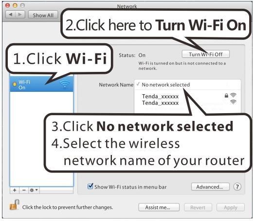
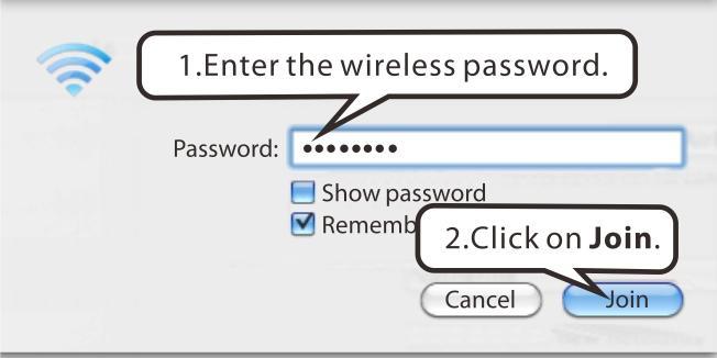
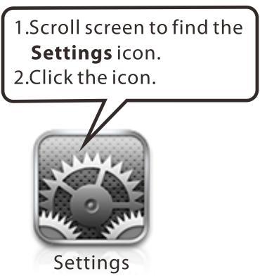
105 iphone/ipad 101


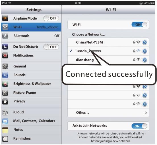
106 102 Wireless Modem Router
Copyright Statement. Disclaimer. Technical Support
 Copyright Statement 2015 Shenzhen Tenda Technology Co., Ltd. All rights reserved. Tenda is a registered trademark legally held by Shenzhen Tenda Technology Co., Ltd. Other brand and product names mentioned
300Mbps Wireless N VDSL2 Modem Router. User Guide
 300Mbps Wireless N VDSL2 Modem Router User Guide 1 Copyright Statement 2017 Shenzhen Tenda Technology Co., Ltd. All rights reserved. is a registered trademark legally held by Shenzhen Tenda Technology
User Guide. 300Mbps Wireless N USB ADSL2+ Modem Router TD-W8968 REV
 User Guide 300Mbps Wireless N USB ADSL2+ Modem Router TD-W8968 REV 5.1.0 1910011943 CONTENTS About This Guide... 1 Chapter 1. Product Overview... 2 1.1 Overview of the Modem Router... 2 1.2 Product Appearance...
OV303R6. User Manual
 OV303R6 User Manual Contents 1 Safety Precautions... 1 2 2 Overview... 2.1 Application... 2 2.2 Features... 2 2.3 Standards Compatibility and Compliance... 3 3 Hardware Description and Hardware Installation...
ADSL User Manual. Wireless-N BROADBAND ROUTER : Introduction
 ADSL User Manual 1 : Introduction The ADSL is a communication terminal, which integrates ADSL access, broadband SOHO router, WLAN and VoIP service. This device can provide high data transmission, downstream
D810R ADSL2+ Router User Guide
 Copyright Statement is the registered trademark of Shenzhen Tenda Technology Co., Ltd. Other trademark or trade name mentioned herein are the trademark or registered trademark of the company. Copyright
OV504R6. Quick Start Guide
 OV504R6 Quick Start Guide 1 Overview The router is a highly ADSL2/2+ Integrated Access Device and can support ADSL link with downstream up to 24 Mbps and upstream up to 1 Mbps. It is designed to provide
COPYRIGHT. Edimax Technology Co., Ltd. Add: No. 3, Wu-Chuan 3 rd Rd., Wu-Ku Industrial Park, New Taipei City, Taiwan.
 COPYRIGHT Copyright Edimax Technology Co., Ltd. all rights reserved. No part of this publication may be reproduced, transmitted, transcribed, stored in a retrieval system, or translated into any language
User Manual. VDSL2 Router with 11n WiFi. Model:DV2211
 Model:DV2211 User Manual VDSL2 Router with 11n WiFi Model:DV2211 V33 User Manual 1 Model:DV2211 TABLE OF CONTENTS... 1 Device Installation... 4 Power on Router... 4 Factory Reset Button... 5 Network Connections...
User Guide TL-R470T+/TL-R480T REV9.0.2
 User Guide TL-R470T+/TL-R480T+ 1910012468 REV9.0.2 September 2018 CONTENTS About This Guide Intended Readers... 1 Conventions... 1 More Information... 1 Accessing the Router Overview... 3 Web Interface
Broadband High-Speed DSL Modem User Manual
 Broadband High-Speed DSL Modem User Manual Model DM200 September 2017 202-11621-03 350 E. Plumeria Drive San Jose, CA 95134 USA Support Thank you for purchasing this NETGEAR product. You can visit www.netgear.com/support
LevelOne FBR User s Manual. 1W, 4L 10/100 Mbps ADSL Router. Ver
 LevelOne FBR-1416 1W, 4L 10/100 Mbps ADSL Router User s Manual Ver 1.00-0510 Table of Contents CHAPTER 1 INTRODUCTION... 1 FBR-1416 Features... 1 Package Contents... 3 Physical Details... 3 CHAPTER 2
CHAPTER 7 ADVANCED ADMINISTRATION PC
 ii Table of Contents CHAPTER 1 INTRODUCTION... 1 Broadband ADSL Router Features... 1 Package Contents... 3 Physical Details... 4 CHAPTER 2 INSTALLATION... 6 Requirements... 6 Procedure... 6 CHAPTER 3 SETUP...
IP806GA/GB Wireless ADSL Router
 IP806GA/GB Wireless ADSL Router 802.11g/802.11b Wireless Access Point ADSL Modem NAT Router 4-Port Switching Hub User's Guide Table of Contents CHAPTER 1 INTRODUCTION... 1 Wireless ADSL Router Features...
User Manual VER: 1.0
 OV604VB VER: 1.0 Contents 1 Safety Precautions... 1 2 Overview... 2 2.1 Application... 2 2.2 Features... 2 2.3 Standards Compatibility and Compliance... 3 3 Hardware Description and Installation... 5 3.1
DVA-G3340S High-Speed 2.4 GHz Wireless ADSL VOIP Router. Manual
 DVA-G3340S High-Speed 2.4 GHz Wireless ADSL VOIP Router Manual Contents Package Contents...4 Introduction...5 Features...8 Using the Web Interface...9 Home > Wizard...9 Home > Wireless...10 Home > Wireless
N150 WiFi DSL Modem Router Essentials Edition. N300 WiFi DSL Modem Router Essentials Edition
 N150 WiFi DSL Modem Router Essentials Edition Model D500 N300 WiFi DSL Modem Router Essentials Edition Model D1500 User Manual May 2018 202-11390-02 350 East Plumeria Drive San Jose, CA 95134 USA Support
Configuration Guide TL-ER5120/TL-ER6020/TL-ER REV3.0.0
 Configuration Guide TL-ER5120/TL-ER6020/TL-ER6120 1910012186 REV3.0.0 June 2017 CONTENTS About This Guide Intended Readers... 1 Conventions... 1 More Information... 1 Viewing Status Information... 2 System
DSL-X11. One Port ADSL Modem Router. User Manual
 DSL-X11 One Port ADSL Modem Router User Manual Contents 1 Introduction... 1 1.1 Features... 1 1.2 ADSL Standard Supports... 1 1.3 Encapsulation Supports... 1 1.4 System Requirements... 2 1.5 LED Status
Table of Contents. D-Link DSL-2730U User Manual 1
 Table of Contents D-Link DSL-2730U User Manual 1 Table of Contents PACKAGE CONTENTS... 4 SYSTEM REQUIREMENTS... 4 FEATURES... 5 HARDWARE OVERVIEW... 7 Connections... 7 LEDs... 8 INSTALLATION... 9 BEFORE
LevelOne WBR User s Manual. 11g Wireless ADSL VPN Router. Ver
 LevelOne WBR-3407 11g Wireless ADSL VPN Router User s Manual Ver 1.00-0510 Table of Contents CHAPTER 1 INTRODUCTION... 1 Wireless ADSL Router Features... 1 Package Contents... 5 Physical Details... 6 CHAPTER
300M MIMO Triple Smart Router
 Model No. ib-wrt300n User Manual 1910020722 FCC STATEMENT This equipment has been tested and found to comply with the limits for a Class B digital device, pursuant to part 15 of the FCC Rules. These limits
802.11N Wireless ADSL Router
 802.11N Wireless ADSL Router Pre-N Wireless Access Point ADSL Modem NAT Router WPS 4-Port Switching Hub User's Guide Table of Contents CHAPTER 1 INTRODUCTION...1 Wireless ADSL Router Features...1 Package
3G-6408n User Manual
 3G-6408n User Manual 05-2012 / v1.0 COPYRIGHT Copyright Edimax Technology Co., Ltd. all rights reserved. No part of this publication may be reproduced, transmitted, transcribed, stored in a retrieval system,
Content 1 OVERVIEW HARDWARE DESCRIPTION HARDWARE INSTALLATION PC CONFIGURATION GUIDE... 5 WEB-BASED MANAGEMENT GUIDE...
 Content 1 OVERVIEW...1 1.1FEATURES...1 1.2 PACKETCONTENTS...3 1.3 SYSTEM REQUIREMENTS... 1.4 FACTORY DEFAULTS...4 1.5 WARNINGS AND CAUTIONS...4 2 HARDWARE DESCRIPTION... 6 3 HARDWARE INSTALLATION...8 4
Table of Contents. D-Link DSL-2750U User Manual 1
 Table of Contents D-Link DSL-2750U User Manual 1 Table of Contents Table of Contents TABLE OF CONTENTS... 2 PACKAGE CONTENTS... 4 SYSTEM REQUIREMENTS... 4 FEATURES... 5 HARDWARE OVERVIEW... 7 Connections...
OV804WVA. User Manual
 OV804WVA User Manual VER: 1.0 OvisLink (Canada) INC User Manual Contents 1 Safety Precautions... 1 2 Overview... 2 2.1 Application... 2 2.2 Features... 3 2.3 Standards Compatibility and Compliance... 4
NWAR3650 User Manual
 NWAR3650 User Manual Contents 1 Introduction... 1 1.1 Application... 1 1.2 Environment Requirements... 1 1.3 System Requirements... 2 1.4 Safety Cautions... 2 1.5 LED Status Description... 2 1.5.1 Front
SR630n. User Manual VER: 1.0
 SR630n VER: 1.0 Contents 1 Safety Precautions... 1 2 Overview... 2 2.1 Application... 2 2.2 Features... 3 2.3 Standards Compatibility and Compliance... 4 3 Hardware Description and Installation... 5 3.1
User s Guide. GPT-2541GNAC Indoor GPON HGU. Default Login Details. User Name: admin Password: 1234
 User s Guide GPT-2541GNAC Indoor GPON HGU Default Login Details http://192.168.1.1 User Name: admin Password: 1234 Firmware Version 1.00 Edition 1, 9/2015 IMPORTANT! READ CAREFULLY BEFORE USE. KEEP THIS
Introduction... 3 Features... 3 Minimum Requirements... 3 Package Content... 3 Note... 3 Get to know the Broadband Router... 4 Back Panel...
 Introduction... 3 Features... 3 Minimum Requirements... 3 Package Content... 3 Note... 3 Get to know the Broadband Router... 4 Back Panel... 4 Front Panel... 5 Setup Diagram... 6 Getting started... 7 Chapter
LKR Port Broadband Router. User's Manual. Revision C
 LKR-604 4-Port Broadband Router User's Manual Revision C 1 Contents 1 Introduction... 4 1.1 Features... 4 1.2 Package Contents... 4 1.3 Finding Your Way Around... 5 1.3.1 Front Panel... 5 1.3.2 Rear Panel
Notice according to GNU/GPL-Version 2
 Copyright by Edimax Technology Co, LTD. all rights reserved. No part of this publication may be reproduced, transmitted, transcribed, stored in a retrieval system, or translated into any language or computer
KD216 VDSL Router User Manual
 KD216 VDSL Router NOTICE This document contains proprietary information protected by copyright, and this Manual and all the accompanying hardware, software, and documentation are copyrighted. All rights
Table of Contents. General Information... 4 Package Contents... 4 Important Safety Instructions... 4 Front Panel View... 5 Rear Panel View...
 Table of Contents General Information... 4 Package Contents... 4 Important Safety Instructions... 4 Front Panel View... 5 Rear Panel View... 6 Installing the Modem... 7 Installation Diagram... 9 Configuring
NWAR3600 ADSL 11n Gateway. User s Manual. Version 0.1
 NWAR3600 ADSL 11n Gateway User s Manual Version 0.1 Copyright 2008 Table of Contents 1. INTRODUCTION... 4 1.1 FEATURES... 4 1.2 SYSTEM REQUIREMENTS... 4 2. INSTALLATION... 5 FRONT PANEL... 5 REAR PANEL...
HG531 V1 300Mbps Wireless ADSL2+ Router Product Description. Issue _01 HUAWEI TECHNOLOGIES CO., LTD.
 HG531 V1 300Mbps Wireless ADSL2+ Router Issue 203275_01 HUAWEI TECHNOLOGIES CO., LTD. Copyright Huawei Technologies Co., Ltd. 2013. All rights reserved. No part of this document may be reproduced or transmitted
802.11N Wireless Broadband Router
 802.11N Wireless Broadband Router Pre-N Wireless Access Point Broadband Internet Access WPS 4-Port Switching Hub User's Guide Table of Contents CHAPTER 1 INTRODUCTION... 1 Wireless Router Features... 1
RX3041. User's Manual
 RX3041 User's Manual Table of Contents 1 Introduction... 2 1.1 Features and Benefits... 3 1.2 Package Contents... 3 1.3 Finding Your Way Around... 4 1.4 System Requirements... 6 1.5 Installation Instruction...
DSL-G624T. Wireless ADSL Router. If any of the above items is missing, please contact your reseller. This product can be set up using any
 This product can be set up using any current web browser, i.e., Internet Explorer 6x or Netscape Navigator 7x. DSL-G624T Wireless ADSL Router Before You Begin 1. If you purchased this Router to share your
Table of Contents. D-Link DSL-526B User Manual 1
 1 : Table of Contents PACKAGE CONTENTS... 2 SYSTEM REQUIREMENTS... 2 FEATURES... 3 HARDWARE OVERVIEW... 4 Connections... 4 LEDs... 5 INSTALLATION... 6 BEFORE YOU BEGIN... 6 INSTALLATION NOTES... 7
KW5590 Wireless Router User Manual
 KW5590 Wireless Router NOTICE This document contains proprietary information protected by copyright, and this Manual and all the accompanying hardware, software, and documentation are copyrighted. All
MIMO Wireless Broadband Route r User s Manual 1
 MIMO Wireless Broadband Router User s Manual 1 Introduction...4 Features...4 Minimum Requirements...4 Package Content...4 Note...4 Get to know the Broadband Router...5 Back Panel...5 Front Panel...6 Setup
Wireless Broadband Router
 LW6005A-R2 Wireless Broadband Router Manual 1 Introduction... 4 Features... 4 Minimum Requirements... 4 Package Content... 4 Note... 4 Get to know the Broadband Router... 5 Back Panel... 5 Front Panel...
DSL/CABLE ROUTER with PRINT SERVER
 USER S MANUAL DSL/CABLE ROUTER with PRINT SERVER MODEL No:SP888BP http://www.micronet.info 1 Content Table CHAPTER 0:INTRODUCTION... 4 FEATURES... 4 MINIMUM REQUIREMENTS... 4 PACKAGE CONTENT... 4 GET TO
Introduction... 3 Features... 3 Minimum Requirements... 3 Package Content... 3 Note... 3 Get to know the Broadband Router... 4 Back Panel...
 Introduction... 3 Features... 3 Minimum Requirements... 3 Package Content... 3 Note... 3 Get to know the Broadband Router... 4 Back Panel... 4 Front Panel... 5 Setup Diagram... 6 Getting started... 7 Chapter
300M Wireless-N Broadband Router User Manual
 300M Wireless-N Broadband Router Model No.: ib-wrb314n User Manual Ver.: 1.0.0 Contents...Error! Bookmark not defined. Chapter 1 Product Overview... 3 Package Contents 3 Conventions....4 Panel Overview...
Table of Contents. D-Link DSL-2540U User Manual 1
 Table of Contents D-Link DSL-2540U User Manual 1 Table of Contents PACKAGE CONTENTS...3 SYSTEM REQUIREMENTS...3 FEATURES...4 HARDWARE OVERVIEW...6 Connections...6 LEDs...7 INSTALLATION...8 BEFORE YOU BEGIN...8
V7610-I1. User Manual
 V7610-I1 User Manual Contents 1. Introduction... 4 1.1 Specifications... 4 2. Installation... 5 2.1 Hardware installation... 5 3. Connect to the router... 6 3.1 Setup your local network... 6 3.2 Connect
11N ADSL2+ Modem Router
 User s Manual 11N ADSL2+ Modem Router Model No.: SP3367NL 1 Table of Contents 1. Introduction...2 1.1 Package Contents... 2 1.2 Key Features... 2 1.3 Safety Information... 3 2. Physical Description...5
Broadband Router. User s Manual
 Broadband Router User s Manual 1 Introduction... 4 Features... 4 Minimum Requirements... 4 Package Content... 4 Note... 4 Get to know the Broadband Router... 5 Back Panel... 5 Front Panel... 6 Setup Diagram...7
ALL500VDSL2. WLAN N VDSL Router. User s Manual
 ALL500VDSL2 WLAN N VDSL Router User s Manual NOTICE This document contains proprietary information protected by copyright, and this Manual and all the accompanying hardware, software, and documentation
Broadband Router. with 2 Phone Ports WIRED. Installation and Troubleshooting Guide RT31P2. A Division of Cisco Systems, Inc. Model No.
 A Division of Cisco Systems, Inc. Broadband Router with 2 Phone Ports WIRED Installation and Troubleshooting Guide Model No. RT31P2 Copyright and Trademarks Specifications are subject to change without
ADSL Modem. User Guide AM300. Model No. WIRED
 WIRED User Guide Model No. AM300 Copyright and Trademarks Specifications are subject to change without notice. Linksys is a registered trademark or trademark of Cisco Systems, Inc. and/or its affiliates
EM4568 / EM4569 Router Wireless N ADSL2/2+
 EM4568 / EM4569 Router Wireless N ADSL2/2+ 2 ENGLISH EM4568/EM4569 Router Wireless N ADSL2/2+ Table of contents 1.0 Introduction... 3 1.1 Functions and features... 3 1.2 Packing contents... 3 2.0 Back
NBG-416N. Wireless N-lite Home Router. Default Login Details. IMPORTANT! READ CAREFULLY BEFORE USE.
 NBG-416N Wireless N-lite Home Router IMPORTANT! Default Login Details LAN IP https://192.168.1.1 Address User Name admin Password 1234 READ CAREFULLY BEFORE USE. KEEP THIS GUIDE FOR FUTURE REFERENCE. IMPORTANT!
Atrie DB108-E ADSL MODEM. User Manual V1.1
 Atrie DB108-E ADSL MODEM User Manual V1.1 CONTENTS 1.OVERVIEW...4 1.1 ABOUT ADSL...4 1.2 ABOUT ADSL2/2+...4 1.3 FEATURES...4 2 SPECIFICATION...5 2.1 INTERFACE INTRODUCTION...5 2.1.1 Indicator and Interface...5
LevelOne User Manual WBR g Wireless ADSL2+ Router
 LevelOne User Manual WBR-3600 11g Wireless ADSL2+ Router V1.0.1-0809 1 FCC Statement This equipment has been tested and found to comply with the limits for a Class B digital device, pursuant to Part 15
WIRELESS ROUTER N150. User Manual. F9K1009v1 8820zb01125 Rev.B00
 WIRELESS ROUTER N150 User Manual F9K1009v1 8820zb01125 Rev.B00 TABLE OF CONTENTS Getting Started... 1 What s in the Box...1 Initial Setup...1 How to Set It UP...2 Adding Computers to Your Network...3 Manually
IP806GA/GB Wireless ADSL Router
 IP806GA/GB Wireless ADSL Router 802.11g/802.11b Wireless Access Point ADSL Modem NAT Router 4-Port Switching Hub User's Guide DECLARATION OF CON FORMITY This device complies with Part 15 of the FCC Rules.
LevelOne. User Manual. 11g Wireless ADSL2+ Modem Router WBR Ver. 1.0
 LevelOne User Manual WBR-3601 11g Wireless ADSL2+ Modem Router Ver. 1.0 Table of Contents Product Overview... 3 Product Description... 3 Specification... 4 LED Meaning... 6 Back Panel Connectors... 7 Factory
IP819VGA g ADSL VoIP Gateway
 IP819VGA 802.11g ADSL VoIP Gateway 802.11g/802.11b Access Point ADSL Modem NAT Router VoIP Gateway User's Guide Table of Contents CHAPTER 1 INTRODUCTION... 1 802.11g ADSL VoIP Gateway Features... 1 Package
User Manual DIR-615. Wireless Router with Built-in 4-port Switch
 DIR-615 Wireless Router with Built-in 4-port Switch December 2011 Contents Chapter 1. Introduction...4 Contents and Audience...4 Conventions...4 Document Structure...4 Chapter 2. Overview...5 General Information...5
User s Guide DSL-2401HN2-E1C
 User s Guide DSL-2401HN2-E1C 1st Edition, Mar,2017 IMPORTANT! READ CAREFULLY BEFORE USE. KEEP THIS GUIDE FOR FUTURE REFERENCE. Graphics in this book may differ slightly from the product due to differences
User Manual DIR-615. Wireless N 300 Home Router
 DIR-615 Wireless N 300 Home Router April 2013 Contents Chapter 1. Introduction...5 Contents and Audience...5 Conventions...5 Document Structure...5 Chapter 2. Overview...6 General Information...6 Specifications...7
Table of Contents. DSL-504T User s Manual. Table of Contents. Table of Contents...2. Package Contents...4. Installation Overview...
 Table of Contents Table of Contents Table of Contents...2 Package Contents...4 Installation Overview...5 Installation Requirements...6 Information you will need from your ADSL service provider...8 Information
UIP1869V User Interface Guide
 UIP1869V User Interface Guide (Firmware version 0.1.8 and later) Table of Contents Opening the UIP1869V's Configuration Utility... 3 Connecting to Your Broadband Modem... 5 Setting up with DHCP... 5 Updating
CHAPTER 7 ADVANCED ADMINISTRATION PC
 Table of Contents CHAPTER 1 INTRODUCTION... 1 54Mbps 802.11g ADSL Firewall Modem Router Features... 2 Package Contents... 4 Physical Details... 5 CHAPTER 2 INSTALLATION... 7 Requirements... 7 Procedure...
VB104W VDSL. User Manual
 VB104W VDSL User Manual Contents 1 Safety Precautions... 1 2 Overview... 2 2.1 Packing List... 2 2.2 Application... 2 2.3 Features... 3 2.4 Standards Compatibility and Compliance... 4 3 Hardware Description
User Manual. AC ac Wireless Access Point/Router. Model WAC124. NETGEAR, Inc.
 AC2000 802.11ac Wireless Access Point/Router Model WAC124 December 2018 202-11885-02 NETGEAR, Inc. 350 E. Plumeria Drive San Jose, CA 95134, USA AC2000 802.11ac Support Thank you for purchasing this NETGEAR
N300 Wireless Gigabit ADSL2+ Modem Router DGN3500
 N300 Wireless Gigabit ADSL2+ Modem Router DGN3500 User Manual 350 East Plumeria Drive San Jose, CA 95134 USA June 2010 202-10487-02 v1.0 2010 NETGEAR, Inc. All rights reserved. No part of this publication
Wireless b/g/n 150Mbps AP Router
 Wireless 802.11b/g/n 150Mbps AP Router User Manual V1.2 2009-11-30 Package Contents The following items should be found in your package: One Wireless 802.11b/g/n 150Mbps Broadband Router One DC 9v power
VMG4825-B10A. User s Guide. Quick Start Guide. Wireless N VDSL2 IAD with USB. Default Login Details. Version 5.11 Edition 1, 05/2016
 VMG4825-B10A Wireless N VDSL2 IAD with USB Version 5.11 Edition 1, 05/2016 Quick Start Guide User s Guide Default Login Details LAN IP Address http://192.168.1.1 Login admin, user www.zyxel.com Password
BR-6428HPn User Manual
 BR-6428HPn User Manual 05-2012 / v1.0 COPYRIGHT Copyright Edimax Technology Co., Ltd. all rights reserved. No part of this publication may be reproduced, transmitted, transcribed, stored in a retrieval
A5500 Configuration Guide
 A5500 Configuration Guide Sri Ram Kishore February 2012 Table of contents Gateway Configuration... 3 Accessing your gateway configuration tool... 3 Configuring your broadband Internet access... 3 Configuring
TABLE OF CONTENT 1. ABOUT THIS GUIDE Overview of the User s Guide INTRODUCTION Overview Features...
 TABLE OF CONTENT 1. ABOUT THIS GUIDE... 3 1.1 Overview of the User s Guide... 3 2. INTRODUCTION... 3 2.1 Overview... 3 2.2 Features... 3 2.3 Panel Layout... 4 2.3.1 Front Panel... 4 2.3.2 Rear Panel...
AirCruiser G Wireless Router GN-BR01G
 AirCruiser G Wireless Router GN-BR01G User s Guide i Contents Chapter 1 Introduction... 1 Overview...1 Features...1 Package Contents...2 AirCruiser G Wireless Router Rear Panel...2 AirCruiser G Wireless
A Division of Cisco Systems, Inc. Broadband Router. with 2 Phone Ports. User Guide WIRED RT41P2-AT. Model No.
 A Division of Cisco Systems, Inc. WIRED Broadband Router with 2 Phone Ports User Guide Model No. RT41P2-AT Copyright and Trademarks Specifications are subject to change without notice. Linksys is a registered
User Manual. Rev:
 Default Login Details Login Address: www.mykasda.com Login Password: Set up by users Default Wi-Fi SSID: Kasda xxxx KW6516 (Printed on product label) Default Wi-Fi Password: 12345678 www.kasdanet.com Rev:
GHz 2, g. Wireless-G. User Guide. ADSL Home Gateway WIRELESS WAG200G (EU) Model No.
 Model No.") GHz 2,4 802.11g WIRELESS Wireless-G ADSL Home Gateway User Guide Model No. WAG200G (EU) Copyright and Trademarks Specifications are subject to change without notice. Linksys is a registered trademark or
GHz 2,4 802.11g WIRELESS Wireless-G ADSL Home Gateway User Guide Model No. WAG200G (EU) Copyright and Trademarks Specifications are subject to change without notice. Linksys is a registered trademark or
Introduction... 3 Features... 3 Minimum Requirements... 3 Package Content... 3 Get to know the Broadband Router... 4 Back Panel... 4 Front Panel...
 Introduction... 3 Features... 3 Minimum Requirements... 3 Package Content... 3 Get to know the Broadband Router... 4 Back Panel... 4 Front Panel... 5 Setup Diagram... 6 Getting started... 7 Chapter 1...
ZXV10 W300 Wireless ADSL Router. Quick Installation Manual ZTE CORPORATION
 ZXV10 W300 Wireless ADSL Router Quick Installation Manual ZTE CORPORATION 1 ZXV10 W300 Wireless ADSL Router Quick Installation Manual Manual version 20060810-R1.0 Product version Copyright 2005 ZTE CORPORATION
Multi-Homing Broadband Router. User Manual
 Multi-Homing Broadband Router User Manual 1 Introduction... 4 Features... 4 Minimum Requirements... 4 Package Content... 4 Note... 4 Get to know the Broadband Router... 5 Back Panel... 5 Front Panel...
D-Link DSR Series Router
 D-Link DSR Series Router U s e r M a n u a l Copyright 2010 TeamF1, Inc. All rights reserved Names mentioned are trademarks, registered trademarks or service marks of their respective companies. Part No.:
Calix T07xG HGU ONT Operation and Maintenance Guide
 Calix T07xG HGU ONT Operation and Maintenance Guide July 2013 #220-00589, Rev 10 Contents About This Document... 5 Revision History... 6 Product Introduction... 7 Chapter 1: ONT Configuration... 11 Web
Quick Installation Guide DSL-2650U/NRU. 3G/ADSL/Ethernet Router with Wi-Fi and Built-in Switch
 DSL-2650U/NRU 3G/ADSL/Ethernet Router with Wi-Fi and Built-in Switch BEFORE YOU BEGIN Delivery Package Router DSL-2650U/NRU Power adapter RJ-11 telephone cable Straight-through Ethernet cable (CAT 5E)
RANGER SERIES. ADSL2/2+ Ethernet Broadband Router DG-BG1000. ADSL 2/2+ 24 Mbps V
 RANGER SERIES ADSL2/2+ Ethernet Broadband Router DG-BG1000 ADSL 2/2+ 24 Mbps V1.0 2011-12-13 Copyright 2011. All rights reserved. Company has an on-going policy of upgrading its products and it may be
User Manual. OT-1044ns
 User Manual OT-1044ns CONTENTS Chapter 1 Introduction... 3 1.1 Features... 3 1.2 Environments... 3 1.3 System Requirement... 4 Chapter 2 Hardware Installation... 4 2.1 Led indicators... 4 2.2 Back Panel
User Guide. N300 Wireless Gigabit VDSL/ADSL Modem Router TD-W9977 REV
 User Guide N300 Wireless Gigabit VDSL/ADSL Modem Router TD-W9977 REV1.0.0 1910011880 Contents About This Guide..................................................... 1 Chapter 1. Get to Know Your Modem Router.........................
Version /06/2016. User Manual. Wireless N300 ADSL2+ Modem Router DSL-124
 Version 1.00 04/06/2016 User Manual Wireless N300 ADSL2+ Modem Router DSL-124 Preface D-Link reserves the right to revise this publication and to make changes in the content hereof without obligation to
How to change your WiFi name and password? How to enable/disable your WiFi according to schedule? How to extend your wireless range?
 1 Copyright Statement Copyright Statement 2015 Shenzhen Tenda Technology Co., Ltd. All rights reserved. Tenda is a registered trademark legally held by Shenzhen Tenda Technology Co., Ltd. Other brand and
AC1200 WiFi Router User Manual
 AC1200 WiFi Router User Manual Model R6120 September 2017 202-11753-03 350 E. Plumeria Drive San Jose, CA 95134 USA Support Thank you for purchasing this NETGEAR product. You can visit www.netgear.com/support
CAUTION: Any changes or modifications not expressly approved by the grantee of this device could void the user's authority to operate the equipment.
 FCC Notices This device complies with Part 15 of the FCC Rules. Operation is subject to the following two conditions: (1) this device may not cause harmful interference, and (2) this device must accept
LevelOne FBR-1405TX. User s Manual. 1-PORT BROADBAND ROUTER W/4 LAN Port
 LevelOne FBR-1405TX 1-PORT BROADBAND ROUTER W/4 LAN Port User s Manual 1 Introduction... 4 Features... 4 Minimum Requirements...4 Package Content... 4 Note...4 Get to know the Broadband Router... 5 Back
User Manual DIR-850L. Wireless AC1200 Dual Band Gigabit Router.
 User Manual DIR-850L Wireless AC1200 Dual Band Gigabit Router USER MANUAL: DIR-850L Wireless AC1200 Dual Band Gigabit Router SYSTEM REQUIREMENTS Network Requirements Web-based Configuration Utility Requirements
Wireless N300 Home Router
 Copyright Statement is the registered trademark of Shenzhen Tenda Technology Co., Ltd. All the products and product names mentioned herein are the trademarks or registered trademarks of their respective
TD-W Mbps Wireless N USB ADSL2+ Modem Router REV:
 TD-W8968 300Mbps Wireless N USB ADSL2+ Modem Router REV: 5.0.0 1910011586 COPYRIGHT & TRADEMARKS Specifications are subject to change without notice. is a registered trademark of TP-LINK TECHNOLOGIES CO.,
Network Tools Routing NAT FTPD FTPD Account Logout Management...
 VB204W User Manual Table of Contents 1 Safety Precautions... 1 2 Overview... 2 2.1 Packing List... 2 2.2 Application... 2 2.3 Features... 3 2.4 Standards Compatibility and Compliance... 4 3 Hardware Description
Orbi WiFi System User Manual
 User Manual February 2018 202-11675-09 350 E. Plumeria Drive San Jose, CA 95134 USA Support Thank you for purchasing this NETGEAR product. You can visit www.netgear.com/support to register your product,
w w w.apc.com APC 3-in-1 Wireless Mobile Router User s Manual
 w w w.apc.com APC 3-in-1 Wireless Mobile Router User s Manual 990-2149 Copyright 2005 American Power Conversion. All rights reserved. American Power Conversion and TravelPower are registered trademarks