CCNA Exploration Network Fundamentals. Chapter 09 Ethernet
|
|
|
- Aubrey Barber
- 6 years ago
- Views:
Transcription
1 CCNA Exploration Network Fundamentals Chapter 09 Ethernet Updated: 07/07/2008 1
2 9.0.1 Introduction 2
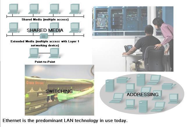
3 9.0.1 Introduction Internet Engineering Task Force (IETF) maintains the functional protocols and services for the TCP/IP protocol suite in the upper layers. However, the functional protocols and services at the OSI Data Link layer and Physical layer are described by various engineering organizations (IEEE, ANSI, ITU) or by private companies (proprietary protocols). Ethernet is comprised of standards at these lower layers, it may best be understood in reference to the OSI model. The OSI model separates the Data Link layer functionalities of addressing, framing and accessing the media from the Physical layer standards of the media. Ethernet standards define both the Layer 2 protocols and the Layer 1 technologies. Although Ethernet specifications support different media, bandwidths, and other Layer 1 and 2 variations, the basic frame format and address scheme is the same for all varieties of Ethernet. Ethernet has evolved from a shared media, contention-based data communications technology to today's high bandwidth, full-duplex technology. 3

4 9.1 Overview of Ethernet Ethernet Standards and Implementation IEEE Standards The first LAN in the world was the original version of Ethernet. Robert Metcalfe and his coworkers at Xerox designed it more than thirty years ago. The first Ethernet standard was published in 1980 by a consortium of Digital Equipment Corporation, Intel, and Xerox (DIX). Metcalfe wanted Ethernet to be a shared standard from which everyone could benefit, and therefore it was released as an open standard. The first products that were developed from the Ethernet standard were sold in 4 the early 1980s.

5 9.1.2 Ethernet Layer 1 and 2 5

6 9.1.3 Logical Link Control Connecting to the Upper Layers 6
.")
7 9.1.3 Logical Link Control Connecting to the Upper Layers LLC is implemented in software, and its implementation is independent of the physical equipment. In a computer, the LLC can be considered the driver software for the Network Interface Card (NIC). The NIC driver is a program that interacts directly with the hardware on the NIC to pass the data between the media and the Media Access Control sublayer MAC Getting Data to the Media 7
8 9.1.4 MAC Getting Data to the Media Logical Topology The underlying logical topology of Ethernet is a multiaccess bus. This means that all the nodes (devices) in that network segment share the medium. This further means that all the nodes in that segment receive all the frames transmitted by any node on that segment. Because all the nodes receive all the frames, each node needs to determine if a frame is to be accepted and processed by that node. This requires examining the addressing in the frame provided by the MAC address. Ethernet provides a method for determining how the nodes share access to the media. The media access control method for classic Ethernet is Carrier Sense Multiple Access with Collision Detection (CSMA/CD). 8
9 9.1.5 Physical Implementations of Ethernet Most of the traffic on the Internet originates and ends with Ethernet connections. Since its inception in the 1970s, Ethernet has evolved to meet the increased demand for high-speed LANs. When optical fiber media was introduced, Ethernet adapted to this new technology to take advantage of the superior bandwidth and low error rate that fiber offers. Today, the same protocol that transported data at 3 Mbps can carry data at 10 Gbps. The success of Ethernet is due to the following factors: Simplicity and ease of maintenance Ability to incorporate new technologies Reliability Low cost of installation and upgrade The introduction of Gigabit Ethernet has extended the original LAN technology to distances that make Ethernet a Metropolitan Area Network (MAN) and WAN standard. 9
10 9.1.5 Physical Implementations of Ethernet As a technology associated with the Physical layer, Ethernet specifies and implements encoding and decoding schemes that enable frame bits to be carried as signals across the media. Ethernet devices make use of a broad range of cable and connector specifications. In today's networks, Ethernet uses UTP copper cables and optical fiber to interconnect network devices via intermediary devices such as hubs and switches. With all of the various media types that Ethernet supports, the Ethernet frame structure remains consistent across all of its physical implementations. It is for this reason that it can evolve to meet today's networking requirements. 10
11 9.2 Ethernet Communication through the LAN Historic Ethernet 11

12 9.2.1 Historic Ethernet 12

13 9.3.2 The Ethernet MAC Address 13

14 9.3.4 Another Layer of Addressing 14
15 9.3.5 Ethernet Unicast, Multicast and Broadcast In Ethernet, different MAC addresses are used for Layer 2 unicast, multicast, and broadcast communications. Unicast A unicast MAC address is the unique address used when a frame is sent from a single transmitting device to single destination device. For example, a host with IP address (source) requests a web page from the server at IP address For a unicast packet to be sent and received, a destination IP address must be in the IP packet header. A corresponding destination MAC address must also be present in the Ethernet frame header. The IP address and MAC address combine to deliver data to one specific destination host. 15
16 9.3.5 Ethernet Unicast, Multicast and Broadcast Broadcast With a broadcast, the packet contains a destination IP address that has all ones (1s) in the host portion. This numbering in the address means that all hosts on that local network (broadcast domain) will receive and process the packet. Many network protocols, such as Dynamic Host Configuration Protocol (DHCP) and Address Resolution Protocol (ARP), use broadcasts. How ARP uses broadcasts to map Layer 2 to Layer 3 addresses is discussed later in this chapter. A broadcast IP address for a network needs a corresponding broadcast MAC address in the Ethernet frame. On Ethernet networks, the broadcast MAC address is 48 ones displayed as Hexadecimal FF-FF-FF- FF-FF-FF. 16
17 9.3.5 Ethernet Unicast, Multicast and Broadcast Multicast Multicast addresses allow a source device to send a packet to a group of devices. Devices that belong to a multicast group are assigned a multicast group IP address. The range of multicast addresses is from to Because multicast addresses represent a group of addresses (sometimes called a host group), they can only be used as the destination of a packet. The source will always have a unicast address. Examples of where multicast addresses would be used are in remote gaming, where many players are connected remotely but playing the same game, and distance learning through video conferencing, where many students are connected to the same class. 17
18 9.3.5 Ethernet Unicast, Multicast and Broadcast As with the unicast and broadcast addresses, the multicast IP address requires a corresponding multicast MAC address to actually deliver frames on a local network. The multicast MAC address is a special value that begins with E in hexadecimal. The value ends by converting the lower 23 bits of the IP multicast group address into the remaining 6 hexadecimal characters of the Ethernet address. The remaining bit in the MAC address is always a "0". An example is hexadecimal E A. Each hexadecimal character is 4 binary bits. 18
19 9.4 Ethernet Media Access Control Media Access Control in Ethernet 19
20 9.4.1 Media Access Control in Ethernet In a shared media environment, all devices have guaranteed access to the medium, but they have no prioritized claim on it. If more than one device transmits simultaneously, the physical signals collide and the network must recover in order for communication to continue. Collisions are the cost that Ethernet pays to get the low overhead associated with each transmission. Ethernet uses Carrier Sense Multiple Access with Collision Detection (CSMA/CD) to detect and handle collisions and manage the resumption of communications. Because all computers using Ethernet send their messages on the same media, a distributed coordination scheme (CSMA) is used to detect the electrical activity on the cable. A device can then determine when it can transmit. When a device detects that no other computer is sending a frame, or carrier signal, the device will transmit, if it has something to send. 20
21 9.4.2 CSMA/CD The Process 21
22 9.4.2 CSMA/CD The Process Carrier Sense In the CSMA/CD access method, all network devices that have messages to send must listen before transmitting. If a device detects a signal from another device, it will wait for a specified amount of time before attempting to transmit. When there is no traffic detected, a device will transmit its message. While this transmission is occurring, the device continues to listen for traffic or collisions on the LAN. After the message is sent, the device returns to its default listening mode. Multi-access If the distance between devices is such that the latency of one device's signals means that signals are not detected by a second device, the second device may start to transmit, too. The media now has two devices transmitting their signals at the same time. Their messages will propagate across the media until they encounter each other. At that point, the signals mix and the message is destroyed. Although the messages are corrupted, the jumble of remaining signals continues to propagate across the media. 22
23 9.4.2 CSMA/CD The Process Collision Detection When a device is in listening mode, it can detect when a collision occurs on the shared media. The detection of a collision is made possible because all devices can detect an increase in the amplitude of the signal above the normal level. Once a collision occurs, the other devices in listening mode - as well as all the transmitting devices - will detect the increase in the signal amplitude. Once detected, every device transmitting will continue to transmit to ensure that all devices on the network detect the collision. 23
24 9.4.2 CSMA/CD The Process Jam Signal and Random Backoff Once the collision is detected by the transmitting devices, they send out a jamming signal. This jamming signal is used to notify the other devices of a collision, so that they will invoke a backoff algorithm. This backoff algorithm causes all devices to stop transmitting for a random amount of time, which allows the collision signals to subside. After the delay has expired on a device, the device goes back into the "listening before transmit" mode. A random backoff period ensures that the devices that were involved in the collision do not try to send their traffic again at the same time, which would cause the whole process to repeat. But, this also means that a third device may transmit before either of the two involved in the original collision have a chance to retransmit. 24
25 9.4.2 CSMA/CD The Process Hubs and Collision Domains Given that collisions will occur occasionally in any shared media topology - even when employing CSMA/CD - we need to look at the conditions that can result in an increase in collisions. Because of the rapid growth of the Internet: More devices are being connected to the network. Devices access the network media more frequently. Distances between devices are increasing. Hubs were created as intermediary network devices that enable more nodes to connect to the shared media. Also known as multi-port repeaters, hubs retransmit received data signals to all connected devices, except the one from which it received the signals. Hubs do not perform network functions such as directing data based on addresses. 25
26 9.4.2 CSMA/CD The Process Hubs and repeaters are intermediary devices that extend the distance that Ethernet cables can reach. Because hubs operate at the Physical layer, dealing only with the signals on the media, collisions can occur between the devices they connect and within the hubs themselves. Further, using hubs to provide network access to more users reduces the performance for each user because the fixed capacity of the media has to be shared between more and more devices. The connected devices that access a common media via a hub or series of directly connected hubs make up what is known as a collision domain. A collision domain is also referred to as a network segment. Hubs and repeaters therefore have the effect of increasing the size of the collision domain. 26
27 9.4.2 CSMA/CD The Process The interconnection of hubs form a physical topology called an extended star. The extended star can create a greatly expanded collision domain. An increased number of collisions reduces the network's efficiency and effectiveness. Although CSMA/CD is a frame collision management system, it was designed to manage collisions for only limited numbers of devices and on networks with light network usage. Therefore, other mechanisms are required when large numbers of users require access and when more active network access is needed. Using switches in place of hubs can begin to alleviate this problem. 27
28 9.4.3 Ethernet Timings Latency - The electrical signal that is transmitted takes a certain amount of time (latency) to propagate (travel) down the cable. Each hub or repeater in the signal's path adds latency as it forwards the bits from one port to the next. Bit Time - For each different media speed, a period of time is required for a bit to be placed and sensed on the media. This period of time is referred to as the bit time. Slot Time - In half-duplex Ethernet, where data can only travel in one direction at once, slot time becomes an important parameter in determining how many devices can share a network. For all speeds of Ethernet transmission at or below 1000 Mbps, the standard describes how an individual transmission may be no smaller than the slot time. Interframe Spacing - The Ethernet standards require a minimum spacing between two non-colliding frames. This gives the media time to stabilize after the transmission of the previous frame and time for the devices to process the frame. Referred to as the interframe spacing, this time is measured from the last bit of the FCS field of one frame to the first bit of the Preamble of the next frame. 28

29 9.5 Ethernet Physical Layer Overview of Ethernet Physical Layer 29
30 9.5.1 Overview of Ethernet Physical Layer The differences between standard Ethernet, Fast Ethernet, Gigabit Ethernet, and 10 Gigabit Ethernet occur at the Physical layer, often referred to as the Ethernet PHY. Ethernet is covered by the IEEE standards. Four data rates are currently defined for operation over optical fiber and twisted-pair cables: 10 Mbps - 10Base-T Ethernet 100 Mbps - Fast Ethernet 1000 Mbps - Gigabit Ethernet 10 Gbps - 10 Gigabit Ethernet There are many different implementations of Ethernet at these various data rates, only the more common ones will be presented. 30

31 and 100 Mbps Ethernet 31
32 and 100 Mbps Ethernet 10 Mbps Ethernet - 10BASE-T 10BASE-T uses Manchester-encoding over two unshielded twistedpair cables. The early implementations of 10BASE-T used Cat3 cabling. However, Cat5 or later cabling is typically used today. 10 Mbps Ethernet is considered to be classic Ethernet and uses a physical star topology. Ethernet 10BASE-T links could be up to 100 meters in length before requiring a hub or repeater. 10BASE-T uses two pairs of a four-pair cable and is terminated at each end with an 8-pin RJ-45 connector. The pair connected to pins 1 and 2 are used for transmitting and the pair connected to pins 3 and 6 are used for receiving. 10BASE-T is generally not chosen for new LAN installations. However, there are still many 10BASE-T Ethernet networks in existence today. The replacement of hubs with switches in 10BASE-T networks has greatly increased the throughput available to these networks and has given Legacy Ethernet greater longevity. The 10BASE-T links connected to a switch can support either half-duplex or full-duplex operation. 32
33 and 100 Mbps Ethernet 100 Mbps - Fast Ethernet In the mid to late 1990s, several new standards were established to describe methods for transmitting data over Ethernet media at 100 Mbps. These standards used different encoding requirements for achieving these higher data rates. 100 Mbps Ethernet, also known as Fast Ethernet, can be implemented using twisted-pair copper wire or fiber media. The most popular implementations of 100 Mbps Ethernet are: 100BASE-TX using Cat5 or later UTP 100BASE-FX using fiber-optic cable Because the higher frequency signals used in Fast Ethernet are more susceptible to noise, two separate encoding steps are used by 100-Mbps Ethernet to enhance signal integrity. 33

34 Mbps Ethernet Ethernet Future Options: Future Ethernet Speeds Although 1-Gigabit Ethernet is now widely available and 10-Gigabit products are becoming more available, the IEEE and the 10-Gigabit Ethernet Alliance are working on 40-, 100-, or even 160-Gbps standards. The technologies that are adopted will depend on a number of factors, including the rate of maturation of the technologies and standards, the rate of adoption in the market, and the cost of emerging products 34
35 9.6.1 Legacy Ethernet Using Hubs Classic Ethernet uses shared media and contention-based media access control. Classic Ethernet uses hubs to interconnect nodes on the LAN segment. Hubs do not perform any type of traffic filtering. Instead, the hub forwards all the bits to every device connected to the hub. This forces all the devices in the LAN to share the bandwidth of the media. Additionally, this classic Ethernet implementation often results in high levels of collisions on the LAN. Because of these performance issues, this type of Ethernet LAN has limited use in today's networks. Ethernet implementations using hubs are now typically used only in small LANs or in LANs with low bandwidth requirements. Sharing media among devices creates significant issues as the network grows. 35
36 9.6.1 Legacy Ethernet Using Hubs Scalability In a hub network, there is a limit to the amount of bandwidth that devices can share. With each device added to the shared media, the average bandwidth available to each device decreases. With each increase in the number of devices on the media, performance is degraded. Latency Network latency is the amount of time it takes a signal to reach all destinations on the media. Each node in a hub-based network has to wait for an opportunity to transmit in order to avoid collisions. Latency can increase significantly as the distance between nodes is extended. Latency is also affected by a delay of the signal across the media as well as the delay added by the processing of the signals through hubs and repeaters. Increasing the length of media or the number of hubs and repeaters connected to a segment results in increased latency. With greater latency, it is more likely that nodes will not receive initial signals, thereby increasing the collisions present in the network. 36
37 9.6.1 Legacy Ethernet Using Hubs Network Failure Because classic Ethernet shares the media, any device in the network could potentially cause problems for other devices. If any device connected to the hub generates detrimental traffic, the communication for all devices on the media could be impeded. This harmful traffic could be due to incorrect speed or full-duplex settings on a NIC. Collisions According to CSMA/CD, a node should not send a packet unless the network is clear of traffic. If two nodes send packets at the same time, a collision occurs and the packets are lost. Then both nodes send a jam signal, wait for a random amount of time, and retransmit their packets. Any part of the network where packets from two or more nodes can interfere with each other is considered a collision domain. A network with a larger number of nodes on the same segment has a larger collision domain and typically has more traffic. As the amount of traffic in the network increases, the likelihood of collisions increases. Switches provide an alternative to the contention-based environment of classic Ethernet. 37

38 9.6.2 Ethernet Using Switches 38
39 9.6.2 Ethernet Using Switches Nodes are Connected Directly In a LAN where all nodes are connected directly to the switch, the throughput of the network increases dramatically. The three primary reasons for this increase are: Dedicated bandwidth to each port Collision-free environment Full-duplex operation These physical star topologies are essentially point to point links. 39
40 9.6.2 Ethernet Using Switches Using Switches Instead of Hubs Most modern Ethernet use switches to the end devices and operate full duplex. Switches provide so much greater throughput than hubs and increase performance so dramatically. However, there are three reasons why hubs are still being used. Availability - LAN switches were not developed until the early 1990s and were not readily available until the mid 1990s. Early Ethernet networks used UTP hubs and many of them remain in operation to this day. Economics - Initially, switches were rather expensive. As the price of switches has dropped, the use of hubs has decreased and cost is becoming less of a factor in deployment decisions. Requirements - The early LAN networks were simple networks designed to exchange files and share printers. For many locations, the early networks have evolved into the converged networks of today, resulting in a substantial need for increased bandwidth available to individual users. In some circumstances, however, a shared media hub will still suffice and these products remain on the market. 40

41 9.6.3 Switches Selective Forwarding 41
42 9.6.3 Switches Selective Forwarding Ethernet switches selectively forward individual frames from a receiving port to the port where the destination node is connected. This selective forwarding process can be thought of as establishing a momentary point-to-point connection between the transmitting and receiving nodes. The connection is made only long enough to forward a single frame. During this instant, the two nodes have a full bandwidth connection between them and represent a logical point-to-point connection. To be technically accurate, this temporary connection is not made between the two nodes simultaneously. In essence, this makes the connection between hosts a point-to-point connection. In fact, any node operating in full-duplex mode can transmit anytime it has a frame, without regard to the availability of the receiving node. This is because a LAN switch will buffer an incoming frame and then forward it to the proper port when that port is idle. This process is referred to as store and forward. 42
43 9.6.3 Switches Selective Forwarding With store and forward switching, the switch receives the entire frame, checks the FCS for errors, and forwards the frame to the appropriate port for the destination node. Because the nodes do not have to wait for the media to be idle, the nodes can send and receive at full media speed without losses due to collisions or the overhead associated with managing collisions. Forwarding is Based on the Destination MAC The switch maintains a table, called a MAC table. that matches a destination MAC address with the port used to connect to a node. For each incoming frame, the destination MAC address in the frame header is compared to the list of addresses in the MAC table. If a match is found, the port number in the table that is paired with the MAC address is used as the exit port for the frame. 43
44 9.6.3 Switches Selective Forwarding The MAC table can be referred to by many different names. It is often called the switch table. Because switching was derived from an older technology called transparent bridging, the table is sometimes called the bridge table. For this reason, many processes performed by LAN switches can contain bridge or bridging in their names. A bridge is a device used more commonly in the early days of LAN to connect - or bridge - two physical network segments. Switches can be used to perform this operation as well as allowing end device connectivity to the LAN. Many other technologies have been developed around LAN switching. One place where bridges are prevalent is in Wireless networks. Wireless Bridges are used to interconnect two wireless network segments. Both terms - switching and bridging are in use by the networking industry. 44
45 9.6.3 Switches Selective Forwarding Switch Operation To accomplish their purpose, Ethernet LAN switches use five basic operations: Learning, Aging. Flooding, Selective Forwarding, Filtering, Learning The MAC table must be populated with MAC addresses and their corresponding ports. The Learning process allows these mappings to be dynamically acquired during normal operation. As each frame enters the switch, the switch examines the source MAC address. Using a lookup procedure, the switch determines if the table already contains an entry for that MAC address. If no entry exists, the switch creates a new entry in the MAC table using the source MAC address and pairs the address with the port on which the entry arrived. The switch now can use this mapping to forward frames to this node. 45
46 9.6.3 Switches Selective Forwarding Aging The entries in the MAC table acquired by the Learning process are time stamped. This timestamp is used as a means for removing old entries in the MAC table. After an entry in the MAC table is made, a procedure begins a countdown, using the timestamp as the beginning value. After the value reaches 0, the entry in the table will be refreshed when the switch next receives a frame from that node on the same port. Flooding If the switch does not know to which port to send a frame because the destination MAC address is not in the MAC table, the switch sends the frame to all ports except the port on which the frame arrived. The process of sending a frame to all segments is known as flooding. The switch does not forward the frame to the port on which it arrived because any destination on that segment will have already received the frame. Flooding is also used for frames sent 46 to the broadcast MAC address.
47 9.6.3 Switches Selective Forwarding Selective Forwarding Selective forwarding is the process of examining a frame's destination MAC address and forwarding it out the appropriate port. This is the central function of the switch. When a frame from a node arrives at the switch for which the switch has already learned the MAC address, this address is matched to an entry in the MAC table and the frame is forwarded to the corresponding port. Instead of flooding the frame to all ports, the switch sends the frame to the destination node via its nominated port. This action is called forwarding. Filtering In some cases, a frame is not forwarded. This process is called frame filtering. One use of filtering has already been described: a switch does not forward a frame to the same port on which it arrived. A switch will also drop a corrupt frame. If a frame fails a CRC check, the frame is dropped. An additional reason for filtering a frame is security. A switch has security settings for blocking frames to and/or from selective MAC addresses or specific ports. 47

48 9.6.4 Ethernet Comparing Hubs and Switches 48
49 9.7.1 ARP Process Mapping IP to MAC Addresses The ARP protocol provides two basic functions: Resolving IPv4 addresses to MAC addresses Maintaining a cache of mappings In the event that the gateway entry is not in the table, the normal ARP process will send an ARP request to retrieve the MAC address associated with the IP address of the router interface. Proxy ARP Using proxy ARP, a router interface acts as if it is the host with the IPv4 address requested by the ARP request. By "faking" its identity, the router accepts responsibility for routing packets to the "real" destination. Another case where a proxy ARP is used is when a host believes that it is directly connected to the same logical network as the destination host. This generally occurs when a host is configured with an improper mask. Yet another use for a proxy ARP is when a host is not configured with a default gateway. By default, Cisco routers have proxy ARP enabled on LAN interfaces. 49
50 9.7.3 The ARP Process Removing Address Mappings For each device, an ARP cache timer removes ARP entries that have not been used for a specified period of time. The times differ depending on the device and its operating system. For example, some Windows operating systems store ARP cache entries for 2 minutes. If the entry is used again during that time, the ARP timer for that entry is extended to 10 minutes. Commands may also be used to manually remove all or some of the entries in the ARP table. After an entry has been removed, the process for sending an ARP request and receiving an ARP reply must occur again to enter the map in the ARP table. The arp command is used to view and to clear the contents of a computer's ARP cache. Note that this command, despite its name, does not invoke the execution of the Address Resolution Protocol in any way. It is merely used to display, add, or remove the entries of the ARP table. ARP service is integrated within the IPv4 protocol and implemented by the device. Its operation is transparent to both upper layer applications and users. 50

51 9.7.4 ARP Broadcasts - Issues 51
Objectives. Hexadecimal Numbering and Addressing. Ethernet / IEEE LAN Technology. Ethernet
 2007 Cisco Systems, Inc. All rights reserved. Cisco Public Objectives Ethernet Network Fundamentals Chapter 9 ITE PC v4.0 Chapter 1 1 Introduce Hexadecimal number system Describe the features of various
Switching & ARP Week 3
 Switching & ARP Week 3 Module : Computer Networks Lecturer: Lucy White lbwhite@wit.ie Office : 324 Many Slides courtesy of Tony Chen 1 Ethernet Using Switches In the last few years, switches have quickly
Chapter 9. Ethernet. Part II
 Chapter 9 Ethernet Part II CCNA1-1 Chapter 9-2 Note for Instructors These presentations are the result of a collaboration among the instructors at St. Clair College in Windsor, Ontario. Thanks must go
10- and 100-Mbps Ethernet
 Ethernet Basics 10-Mbps Ethernet Three 10-Mbps Ethernet standards: 10BASE5 10BASE2 10BASE-T 10BASE2 and 10BASE5 were around more than 20 years and have been replaced by newer alternatives 10BASE-T s use
Chapter 9 Ethernet Part 1
 Chapter 9 Ethernet Part 1 Introduction to Ethernet Ethernet Local Area Networks (LANs) LAN (Local Area Network) - A computer network connected through a wired or wireless medium by networking devices (s,
CCNA Exploration1 Chapter 7: OSI Data Link Layer
 CCNA Exploration1 Chapter 7: OSI Data Link Layer LOCAL CISCO ACADEMY ELSYS TU INSTRUCTOR: STELA STEFANOVA 1 Explain the role of Data Link layer protocols in data transmission; Objectives Describe how the
Lecture (04) Data link layer
 Data link layer") Lecture (04) Data link layer By: Dr. Ahmed ElShafee Standards Overview CSMA/CD Ethernet standards 10 base 5 10 base 2 10 base T Fast Ethernet Gigabit Ethernet ١ ٢ Standards Overview Like most protocols,
Lecture (04) Data link layer By: Dr. Ahmed ElShafee Standards Overview CSMA/CD Ethernet standards 10 base 5 10 base 2 10 base T Fast Ethernet Gigabit Ethernet ١ ٢ Standards Overview Like most protocols,
Data and Computer Communications
 Data and Computer Communications Chapter 16 High Speed LANs Eighth Edition by William Stallings Why High Speed LANs? speed and power of PCs has risen graphics-intensive applications and GUIs see LANs as
Chapter 4 NETWORK HARDWARE
 Chapter 4 NETWORK HARDWARE 1 Network Devices As Organizations grow, so do their networks Growth in number of users Geographical Growth Network Devices : Are products used to expand or connect networks.
EITF25 Internet Techniques and Applications L4: Network Access. Stefan Höst
 EITF25 Internet Techniques and Applications L4: Network Access Stefan Höst Repetition The link layer protocol should make sure that the data is correctly transmitted over the physical link using error
Internetworking is connecting two or more computer networks with some sort of routing device to exchange traffic back and forth, and guide traffic on
 CBCN4103 Internetworking is connecting two or more computer networks with some sort of routing device to exchange traffic back and forth, and guide traffic on the correct path across the complete network
CS 43: Computer Networks Switches and LANs. Kevin Webb Swarthmore College December 5, 2017
 CS 43: Computer Networks Switches and LANs Kevin Webb Swarthmore College December 5, 2017 Ethernet Metcalfe s Ethernet sketch Dominant wired LAN technology: cheap $20 for NIC first widely used LAN technology
Interface The exit interface a packet will take when destined for a specific network.
 The Network Layer The Network layer (also called layer 3) manages device addressing, tracks the location of devices on the network, and determines the best way to move data, which means that the Network
Part3. Local Area Networks (LAN)
") Part3 Local Area Networks (LAN) LAN Characteristics Small geographical area Relatively high data rate Single management Topologies Bus, star, ring Specifications at physical and data link layer mostly
Part3 Local Area Networks (LAN) LAN Characteristics Small geographical area Relatively high data rate Single management Topologies Bus, star, ring Specifications at physical and data link layer mostly
Section 3 Understanding Ethernet and Switch Operations
 Section 3 Understanding Ethernet and Switch Operations Ethernet is the technology of choice for today s LANs. It is fast, has low costs, and is easy to maintain. Today s Ethernet standards support speeds
Introductory to Computer Networks Local Area Networks. Lecture 16 Fall Isfahan University of technology Dr.
 Introductory to Computer Networks Local Area Networks Lecture 16 Fall 2010 Isfahan University of technology Dr. Faramarz Hendessi What is a LAN? Local area means: Private ownership freedom from regulatory
Lecture 8: Switched Ethernet and Collision Domains
 Lecture 8: Switched Ethernet and Collision Domains Dr. Mohammed Hawa Electrical Engineering Department University of Jordan EE426: Communication Networks Ethernet Installations 2 1 Twisted Pair and Fiber
Zarządzanie sieciami telekomunikacyjnymi
 Ethernet The term Ethernet refers to the family of local-area network (LAN) products covered by the IEEE 802.3 standard that defines what is commonly known as the CSMA/CD protocol. Four data rates are
Ethernet Basics. based on Chapter 4 of CompTIA Network+ Exam Guide, 4 th ed., Mike Meyers
 Ethernet Basics based on Chapter 4 of CompTIA Network+ Exam Guide, 4 th ed., Mike Meyers Ethernet Basics History Ethernet Frames CSMA/CD Obsolete versions 10Mbps versions Segments Spanning Tree Protocol
Chapter 5: Ethernet. Introduction to Networks - R&S 6.0. Cisco Networking Academy. Mind Wide Open
 Chapter 5: Ethernet Introduction to Networks - R&S 6.0 Cisco Networking Academy Mind Wide Open Chapter 5 - Sections 5.1 Ethernet Protocol Describe the Ethernet MAC address and frame fields 5.2 LAN Switches
RMIT University. Data Communication and Net-Centric Computing COSC 1111/2061/1110. Lecture 8. Medium Access Control Methods & LAN
 RMIT University Data Communication and Net-Centric Computing COSC 1111/2061/1110 Medium Access Control Methods & LAN Technology Slide 1 Lecture Overview During this lecture, we will Look at several Multiple
Lecture 05 Chapter 16 High Speed LANs
 NET 456 High Speed Networks Lecture 05 Chapter 16 High Speed LANs Dr. Anis Koubaa Reformatted slides from textbook Data and Computer Communications, Ninth Edition by William Stallings, 1 (c) Pearson Education
Principles behind data link layer services
 Data link layer Goals: Principles behind data link layer services Error detection, correction Sharing a broadcast channel: Multiple access Link layer addressing Reliable data transfer, flow control: Done!
Lecture (04) Network Access layer fundamentals I
 Network Access layer fundamentals I") Lecture (04) Network Access layer fundamentals I By: Dr. Ahmed ElShafee Typical LAN Features for Physical layer Typical LAN Features for Data link layer Standards Overview 10BASE2 and 10BASE5 10BASE T
Lecture (04) Network Access layer fundamentals I By: Dr. Ahmed ElShafee Typical LAN Features for Physical layer Typical LAN Features for Data link layer Standards Overview 10BASE2 and 10BASE5 10BASE T
Lecture (04) Network Access layer fundamentals I
 Network Access layer fundamentals I") Lecture (04) Network Access layer fundamentals I By: Dr. Ahmed ElShafee ١ Dr. Ahmed ElShafee, ACU : Fall 2014, Computer Networks II Typical LAN Features for Physical layer Typical LAN Features for Data
Lecture (04) Network Access layer fundamentals I By: Dr. Ahmed ElShafee ١ Dr. Ahmed ElShafee, ACU : Fall 2014, Computer Networks II Typical LAN Features for Physical layer Typical LAN Features for Data
The Link Layer and LANs: Ethernet and Swiches
 The Link Layer and LNs: Ethernet and Swiches EECS3214 2018-03-21 Link layer, LNs: outline 6.1 introduction, services 6.2 error detection, correction 6.3 multiple access protocols 6.4 LNs addressing, RP
Lecture (04 & 05) Data link layer fundamental
 Data link layer fundamental") Lecture (04 & 05) Data link layer fundamental Dr. Ahmed M. ElShafee ١ Agenda Foundation Topics Typical LAN Features for OSI Layer 1 Typical LAN Features for OSI Layer 2 Standards Overview 10BASE2 and 10BASE5
Lecture (04 & 05) Data link layer fundamental Dr. Ahmed M. ElShafee ١ Agenda Foundation Topics Typical LAN Features for OSI Layer 1 Typical LAN Features for OSI Layer 2 Standards Overview 10BASE2 and 10BASE5
Introduction to LAN Protocols
 CHAPTER 2 Chapter Goals Learn about different LAN protocols. Understand the different methods used to deal with media contention. Learn about different LAN topologies. This chapter introduces the various
Medium Access Protocols
 Medium Access Protocols Summary of MAC protocols What do you do with a shared media? Channel Partitioning, by time, frequency or code Time Division,Code Division, Frequency Division Random partitioning
Chapter 4: Network Access
 4.0.1.1 Chapter 4: Network Access To support our communication, the OSI model divides the functions of a data network into layers. Each layer works with the layers above and below to transmit data. 4.0.1.2
LAN PROTOCOLS. Beulah A AP/CSE
 LAN PROTOCOLS Beulah A AP/CSE IEEE STANDARDS In 1985, the Computer Society of the IEEE started a project, called Project 802, to set standards to enable intercommunication among equipment from a variety
LAN Protocols. Required reading: Forouzan 13.1 to 13.5 Garcia 6.7, 6.8. CSE 3213, Fall 2015 Instructor: N. Vlajic
 1 LAN Protocols Required reading: Forouzan 13.1 to 13.5 Garcia 6.7, 6.8 CSE 3213, Fall 2015 Instructor: N. Vlajic What is LAN? 2 Local Area Network (LAN) properties private ownership freedom to choose/change/upgrade
A LAN is a high-speed data network that covers a relatively small geographic area. It typically connects workstations, personal computers, printers,
 CBCN4103 A LAN is a high-speed data network that covers a relatively small geographic area. It typically connects workstations, personal computers, printers, servers, and other devices. LANs offer computer
Introduction to Networking Devices
 Introduction to Networking Devices Objectives Explain the uses, advantages, and disadvantages of repeaters, hubs, wireless access points, bridges, switches, and routers Define the standards associated
GAYATRI COMPUTERS Prepared by : VENKAT.G 1. Module 1: NETWORK BASICS
 GAYATRI COMPUTERS Prepared by : VENKAT.G 1 What is Networking? Module 1: NETWORK BASICS Networking: Connecting two or more computers or network devices(routers/print Servers / Firewall Devices..etc) for
Lecture 4b. Local Area Networks and Bridges
 Lecture 4b Local Area Networks and Bridges Ethernet Invented by Boggs and Metcalf in the 1970 s at Xerox Local area networks were needed to connect computers, share files, etc. Thick or Thin Ethernet Cable
The Internet software layers
 1 2 The Internet software layers SMTP, Telnet, FTP, POP3, IMAP TCP, UDP IP: RIP, BGP, OSPF Ethernet, Wireless LAN, Token Ring Twisted pair, coaxial, microwave, optical fiber 3 4 Ethernet 1973 Xerox s researcher
Ethernet. Network Fundamentals Chapter Cisco Systems, Inc. All rights reserved. Cisco Public 1
 Ethernet Network Fundamentals Chapter 9 1 Objectives Identify the basic characteristics of network media used in Ethernet. Describe the physical and data link features of Ethernet. Describe the function
Image courtesy Cisco Systems, Inc. Illustration of a Cisco Catalyst switch
 by Jeff Tyson If you have read other HowStuffWorks articles on networking or the Internet, then you know that a typical network consists of nodes (computers), a connecting medium (wired or wireless) and
Lecture (04) Network Layer (Physical/Data link) 2
 Network Layer (Physical/Data link) 2") Lecture (04) Network Layer (Physical/Data link) 2 By: Dr. Ahmed ElShafee ١ Dr. Ahmed elshafee, ACU : Spring 2018, CSE401 Computer Networks Agenda Ethernet standards 10 base 5 10 base 2 10 base T Fast Ethernet
Lecture (04) Network Layer (Physical/Data link) 2 By: Dr. Ahmed ElShafee ١ Dr. Ahmed elshafee, ACU : Spring 2018, CSE401 Computer Networks Agenda Ethernet standards 10 base 5 10 base 2 10 base T Fast Ethernet
Data Link Layer -2- Network Access
 EITF25 Internet: Technology and Applications Data Link Layer -2- Network Access 2015, Lecture 03 Kaan Bür Previously on EITF25 Logical Link Control Sublayer Flow control Send data Wait for ACK Error control
Lecture 6: Example LAN: Ethernet
 Lecture 6: Example LAN: Ethernet Dr. Mohammed Hawa Electrical Engineering Department University of Jordan EE426: Communication Networks Network Types Local Area Networks (LANs):privately-owned networks
Local Area Networks. Aloha Slotted Aloha CSMA (non-persistent, 1-persistent, p-persistent) CSMA/CD Ethernet Token Ring
 CSMA/CD Ethernet Token Ring") Local Area Networks Aloha Slotted Aloha CSMA (non-persistent, 1-persistent, p-persistent) CSMA/CD Ethernet Token Ring Networks: Local Area Networks 1 Network Layer Network Layer LLC 802.2 Logical Link
Local Area Networks Aloha Slotted Aloha CSMA (non-persistent, 1-persistent, p-persistent) CSMA/CD Ethernet Token Ring Networks: Local Area Networks 1 Network Layer Network Layer LLC 802.2 Logical Link
Data Link Layer, Part 3 Medium Access Control. Preface
 Data Link Layer, Part 3 Medium Access Control These slides are created by Dr. Yih Huang of George Mason University. Students registered in Dr. Huang's courses at GMU can make a single machine-readable
ECE 4450:427/527 - Computer Networks Spring 2017
 ECE 4450:427/527 - Computer Networks Spring 2017 Dr. Nghi Tran Department of Electrical & Computer Engineering Lecture 5.5: Ethernet Dr. Nghi Tran (ECE-University of Akron) ECE 4450:427/527 Computer Networks
Networking Technologies and Applications
 Networking Technologies and Applications Rolland Vida BME TMIT September 23, 2016 Aloha Advantages: Different size packets No need for synchronization Simple operation If low upstream traffic, the solution
Computer Networks. Lecture 8 Local Area Network, IEEE 802.x
 Computer Networks Lecture 8 Local Area Network, IEEE 802.x Local area network A local area network (LAN) is a computer network that interconnects computers within a limited area such as a home, school,
Internetwork Basic. Possible causes of LAN traffic congestion are
 Internetworking 1 C H A P T E R 2 Internetworking Basics Internetworking Model The OSI Reference Model Ethernet Networking Wireless Networking Data Encapsulation Topic 3 1 Internetwork Basic 4 Possible
IEEE 802 LANs SECTION C
 IEEE 802 LANs SECTION C Outline of the Lecture Basic characteristics of LAN Topology Transmission Media MAC IEEE 802 LANs 802.3 - CSMA/CD based (Ethernet) 802.4 Token bus-based 802.5 Token ring-based Comparison
Data Link Layer -2- Network Access
 EITF25 Internet: Technology and Applications Data Link Layer -2- Network Access 2013, Lecture 03 Kaan Bür, Stefan Höst Previously on EITF25 Logical Link Control Sublayer Flow control Send data Wait for
Chapter 5 Reading Organizer After completion of this chapter, you should be able to:
 Chapter 5 Reading Organizer After completion of this chapter, you should be able to: Describe the operation of the Ethernet sublayers. Identify the major fields of the Ethernet frame. Describe the purpose
Prepared by Agha Mohammad Haidari Network Manager ICT Directorate Ministry of Communication & IT
 Network Basics Prepared by Agha Mohammad Haidari Network Manager ICT Directorate Ministry of Communication & IT E-mail :Agha.m@mcit.gov.af Cell:0700148122 After this lesson,you will be able to : Define
Data Communication. Introduction of Communication. Data Communication. Elements of Data Communication (Communication Model)
") Data Communication Introduction of Communication The need to communicate is part of man s inherent being. Since the beginning of time the human race has communicated using different techniques and methods.
Data Communication Introduction of Communication The need to communicate is part of man s inherent being. Since the beginning of time the human race has communicated using different techniques and methods.
Introduction. High Speed LANs. Emergence of High-Speed LANs. Characteristics of High Speed LANS. Text ch. 6, High-Speed Networks and
 High Speed LANs 3BA33 David Lewis 2 nd Semester 2006-07 3BA33 D.Lewis 2007 1 Characteristics of High Speed LANS 3BA33 D.Lewis 2007 3 Introduction Fast Ethernet and Gigabit Ethernet Fibre Channel High-speed
Module 15: Network Structures
 Module 15: Network Structures Background Topology Network Types Communication Communication Protocol Robustness Design Strategies 15.1 A Distributed System 15.2 Motivation Resource sharing sharing and
Summary of MAC protocols
 Summary of MAC protocols What do you do with a shared media? Channel Partitioning, by time, frequency or code Time Division, Code Division, Frequency Division Random partitioning (dynamic) ALOHA, S-ALOHA,
Redes de Computadores. Medium Access Control
 Redes de Computadores Medium Access Control Manuel P. Ricardo Faculdade de Engenharia da Universidade do Porto 1 » How to control the access of computers to a communication medium?» What is the ideal Medium
The random access methods we study in this chapter have evolved from a very interesting protocol known as ALOHA, which used a very simple procedure
 Multiple Accesses When nodes or stations are connected and use a common link, called a multipoint or broadcast link, we need a multiple-access protocol to coordinate access to the link. The problem of
IEEE standards for local area networks
 IEEE standards for local area networks Telecommunication Networks Group firstname.lastname@polito.it http://www.telematica.polito.it/ COMPUTER NETWORKS Standard for LANs 1 Copyright Quest opera è protetta
OSI Data Link Layer. Network Fundamentals Chapter 7. Version Cisco Systems, Inc. All rights reserved. Cisco Public 1
 OSI Data Link Layer Network Fundamentals Chapter 7 Version 4.0 1 Objectives Explain the role of Data Link layer protocols in data transmission. Describe how the Data Link layer prepares data for transmission
Chapter 10: Local Area Networks
 Chapter 10: Local Area Networks MULTIPLE CHOICE 1. CSMA stands for: a. Client-Server Multi-Access c. Carrier Server Master Application b. Carrier Sense Multiple Access d. none of the above 2. The CD in
1. Data Link Layer (Layer 2)
") 1. Data Link Layer (Layer 2) The Data Link layer provides a means for exchanging data over a common local media. The Data Link layer performs two basic services: Allows the upper layers to access the media
1. Data Link Layer (Layer 2) The Data Link layer provides a means for exchanging data over a common local media. The Data Link layer performs two basic services: Allows the upper layers to access the media
Introduction to LAN Topologies Cabling. 2000, Cisco Systems, Inc. 3-1
 Introduction to LAN Topologies Cabling 2000, Cisco Systems, Inc. 3-1 Objectives Upon completion of this chapter, you will be able to perform the following tasks: Media / Cabling Local Area Network Cabling
Lecture 5 The Data Link Layer. Antonio Cianfrani DIET Department Networking Group netlab.uniroma1.it
 Lecture 5 The Data Link Layer Antonio Cianfrani DIET Department Networking Group netlab.uniroma1.it Link Layer: setting the context two physically connected devices: host-router, router-router, host-host,
Medium Access Control. CSCI370 Lecture 5 Michael Hutt New York Institute of Technology
 Medium Access Control CSCI370 Lecture 5 Michael Hutt New York Institute of Technology The Data Link Layer Logical Link Control (LLC) IEEE 802.2 Standard RFC 1042 Provides three service options Unreliable
Performance Evaluation of Duplex Mode Parameter in A Wired Local Area Network
 Performance Evaluation of Duplex Mode Parameter in A Wired Local Area Network Isizoh A. N. 1, Nwobodo Lois O. 2, Okafor LoisAnthony U. 3, Obute K. C. 4, Nwobodo H. N. 5 Dept. of Electronic and Computer
Computer Networks Principles LAN - Ethernet
 Computer Networks Principles LAN - Ethernet Prof. Andrzej Duda duda@imag.fr http://duda.imag.fr 1 Interconnection structure - layer 3 interconnection layer 3 router subnetwork 1 interconnection layer 2
Principles behind data link layer services:
 Data link layer Goals: Principles behind data link layer services: Error detection, correction Sharing a broadcast channel: Multiple access Link layer addressing Reliable data transfer, flow control Example
Principles behind data link layer services:
 Data link layer Goals: Principles behind data link layer services: Error detection, correction Sharing a broadcast channel: Multiple access Link layer addressing Reliable data transfer, flow control Example
Data Link Layer. Our goals: understand principles behind data link layer services: instantiation and implementation of various link layer technologies
 Data Link Layer Our goals: understand principles behind data link layer services: link layer addressing instantiation and implementation of various link layer technologies 1 Outline Introduction and services
2. LAN Topologies Gilbert Ndjatou Page 1
 2. LAN Topologies Two basic categories of network topologies exist, physical topologies and logical topologies. The physical topology of a network is the cabling layout used to link devices. This refers
Chapter 2. Switch Concepts and Configuration. Part I
 Chapter 2 Switch Concepts and Configuration Part I CCNA3-1 Chapter 2-1 Note for Instructors These presentations are the result of a collaboration among the instructors at St. Clair College in Windsor,
Layer 2 functionality bridging and switching
 Layer 2 functionality bridging and switching BSAD 141 Dave Novak Sources: Network+ Guide to Networks, Dean 2013 Overview Layer 2 functionality Error detection Bridges Broadcast and collision domains How
Computer Networks Medium Access Control. Mostafa Salehi Fall 2008
 Computer Networks Medium Access Control Mostafa Salehi Fall 2008 2008 1 Outline Issues ALOHA Network Ethernet Token Ring Wireless 2 Main Issues Local Area Network (LAN) : Three or more machines are physically
Ethernet Technologies
 Ethernet Technologies CCNA 1 v3 Module 7 NESCOT CATC 1 10 Mbps Ethernet Legacy Ethernet means: 10BASE5 10BASE2 10BASE-T Common features are: frame format timing parameters transmission process basic design
COS 140: Foundations of Computer Science
 COS 140: Foundations of Computer Science ALOHA Network Protocol Family Fall 2017 Homework 2 Introduction 3 Network Protocols.......................................................... 3 Problem.................................................................
Redes de Computadores (RCOMP) 2016/2017. Laboratory Class Script - PL03
 2016/2017. Laboratory Class Script - PL03") Redes de Computadores (RCOMP) 2016/2017 Packet Tracer network configuration simulation tool Shared medium networks and packet switching networks Ethernet technology. IPv4 basic addressing. IPv4 connectivity
Redes de Computadores (RCOMP) 2016/2017 Packet Tracer network configuration simulation tool Shared medium networks and packet switching networks Ethernet technology. IPv4 basic addressing. IPv4 connectivity
Data Link Layer, Part 5. Medium Access Control
 CS 455 Medium Access Control, Page 1 Data Link Layer, Part 5 Medium Access Control These slides are created by Dr. Yih Huang of George Mason University. Students registered in Dr. Huang s courses at GMU
Chapter Seven. Local Area Networks: Part 1. Data Communications and Computer Networks: A Business User s Approach Seventh Edition
 Chapter Seven Local Area Networks: Part 1 Data Communications and Computer Networks: A Business User s Approach Seventh Edition After reading this chapter, you should be able to: State the definition of
More on LANS. LAN Wiring, Interface
 More on LANS Chapters 10-11 LAN Wiring, Interface Mostly covered this material already NIC = Network Interface Card Separate processor, buffers incoming/outgoing data CPU might not be able to keep up network
Lecture 6 The Data Link Layer. Antonio Cianfrani DIET Department Networking Group netlab.uniroma1.it
 Lecture 6 The Data Link Layer Antonio Cianfrani DIET Department Networking Group netlab.uniroma1.it Link Layer: setting the context two physically connected devices: host-router, router-router, host-host,
Introduction to LAN Protocols
 CHAPTER 2 Introduction to LAN Protocols This chapter introduces the various media-access methods, transmission methods, topologies, and devices used in a local area network (LAN). Topics addressed focus
Imi :... Data:... Nazwisko:... Stron:...
 Imi :.................................................... Data:....................... Nazwisko:............................................... Stron:...................... 1. Which of the following protocols
THE OSI MODEL. Application Presentation Session Transport Network Data-Link Physical. OSI Model. Chapter 1 Review.
 THE OSI MODEL Application Presentation Session Transport Network Data-Link Physical OSI Model Chapter 1 Review By: Allan Johnson Table of Contents Go There! Go There! Go There! Go There! Go There! Go There!
LANs and ARP. Networking. Sirindhorn International Institute of Technology Thammasat University. Networking. LANs and ARP.
 Sirindhorn International Institute of Technology Thammasat University Prepared by Steven Gordon on 5 November 2013 Common/Reports/lans-arp.tex, r723 1/22 Contents LANs IEEE 802.3 Address Resolution and
CSCD 330 Network Programming Spring 2017
 CSCD 330 Network Programming Spring 2017 Lecture 18 Link Layer Protocols Continued Who is this? Reading: Chapter 5 Some slides provided courtesy of J.F Kurose and K.W. Ross, All Rights Reserved, copyright
Chapter 4. The Medium Access Control Sublayer. Points and Questions to Consider. Multiple Access Protocols. The Channel Allocation Problem.
 Dynamic Channel Allocation in LANs and MANs Chapter 4 The Medium Access Control Sublayer 1. Station Model. 2. Single Channel Assumption. 3. Collision Assumption. 4. (a) Continuous Time. (b) Slotted Time.
Goal and Outline. Computer Networking. What Do We Need? Today s Story Lecture 3: Packet Switched Networks Peter Steenkiste
 Goal and Outline 15-441 15-641 Computer Networking Lecture 3: Packet Switched Networks Peter Steenkiste Fall 2016 www.cs.cmu.edu/~prs/15 441 F16 Goal: gain a basic understanding of how you can build a
CCNA Exploration Network Fundamentals. Chapter 10 Planning and Cabling Networks
 CCNA Exploration Network Fundamentals Chapter 10 Planning and Cabling Networks Updated: 15/07/2008 1 10.0.1 Introduction 2 10.0.1 Introduction The following have been covered in previous chapters: considered
COS 140: Foundations of Computer Science
 COS 140: Foundations of C S Network Protocol Family Fall 2017 Copyright c 2002 2017 UMaine School of Computing and Information S 1 / 25 Homework Homework Slides, book Chapter 24 on line Homework: All exercises
Chapter 6: Network Communications and Protocols
 Learning Objectives Chapter 6: Network Communications and Protocols Understand the function and structure of packets in a network, and analyze and understand those packets Understand the function of protocols
Ethernet 101 Siemens Industry Inc All rights reserved. usa.siemens.com/industry
 Connected Manufacturing Ethernet 101 usa.siemens.com/industry Why Ethernet Ethernet is Everywhere! Page 2 Ethernet is everywhere Ethernet is the most common computer networking medium Standardization on
Link Layer and Ethernet
 Link Layer and Ethernet 14-740: Fundamentals of Computer Networks Bill Nace Material from Computer Networking: A Top Down Approach, 6 th edition. J.F. Kurose and K.W. Ross traceroute Data Link Layer Multiple
Goals. Fundamentals of Network Media. More topics. Topics. Multiple access communication. Multiple access solutions
 Fundamentals of Network Media Local Area Networks Ursula Holmström Goals Learn the basic concepts related to LAN technologies, for example use of shared media medium access control topologies Know the
Communication (III) Kai Huang
 Kai Huang") Communication (III) Kai Huang Ethernet Turns 40 12/17/2013 Kai.Huang@tum 2 Outline Bus basics Multiple Master Bus Network-on-Chip Examples o SPI o CAN o FlexRay o Ethernet Basic OSI model Real-Time Ethernet
Communication (III) Kai Huang Ethernet Turns 40 12/17/2013 Kai.Huang@tum 2 Outline Bus basics Multiple Master Bus Network-on-Chip Examples o SPI o CAN o FlexRay o Ethernet Basic OSI model Real-Time Ethernet
Question 7: What are Asynchronous links?
 Question 1:.What is three types of LAN traffic? Unicasts - intended for one host. Broadcasts - intended for everyone. Multicasts - intended for an only a subset or group within an entire network. Question2:
Chapter 4. The Medium Access Control Sublayer
 Chapter 4 The Medium Access Control Sublayer The Channel Allocation Problem Static Channel Allocation in LANs and MANs Dynamic Channel Allocation in LANs and MANs Dynamic Channel Allocation in LANs and
Chapter 10: Planning and Cabling Networks
 Chapter 10: Planning and Cabling Networks Before using an IP phone, accessing instant messaging, or conducting any number of other interactions over a data network, we must connect end devices and intermediary
Guide to Networking Essentials, 6 th Edition. Chapter 6: Network Reference Models and Standards
 Guide to Networking Essentials, 6 th Edition Chapter 6: Network Reference Models and Standards Objectives Explain the OSI reference model layers and their relationship to hardware and software Explain
- Hubs vs. Switches vs. Routers -
 1 Layered Communication - Hubs vs. Switches vs. Routers - Network communication models are generally organized into layers. The OSI model specifically consists of seven layers, with each layer representing