Dr e v prasad Dt
|
|
|
- Claude Baker
- 6 years ago
- Views:
Transcription
1 Dr e v prasad Dt
2 Contents Characteristics of Multiprocessors Interconnection Structures Inter Processor Arbitration Inter Processor communication and synchronization Cache Coherence
3 Introduction A multiprocessor system is an interconnection of two or more CPUs with memory and I/O equipment. IOPs are generally not included in the definitions of multiprocessor system unless they have computational facilities comparable to CPUs. Multiprocessor are MIMD system. Multicomputer system includes number of computers connected together by means of communication lines.
4 It improves reliability. If one system fails, the whole system continue to function with perhaps low efficiency. The computation can proceed in parallel in two ways: Multiple independent jobs operate in parallel A single job can be partitioned into multiple parallel tasks Multiprocessor systems are classified by the way their memory is organized: 1. tightly coupled systems (Shared memory) 2. loosely coupled systems (Distributed memory)
5 Interconnection Structures The components of multiprocessor system include: CPUs IOPs I/O devices Memory Interconnection networks for multiprocessor systems are: Time Shared Common Bus Multiport Memory Crossbar Switch Multistage switching network Hypercube System (Binary n- cube)
6 Assessing Network Alternatives Buses excellent cost scalability poor performance scalability Crossbars excellent performance scalability poor cost scalability Multistage interconnects compromise between these extremes


7 Time Shared Common Bus

8 Multiprocessor systems system bus
9 Multiport memory system Employs separate buses between each memory module and each CPU. This is shown in Fig.for four CPUs and four memory modules (MMs). Each processor bus is connected to each memory module (MM) A processor bus consists of the address, data, and control lines required to communicate with memory. The MM is said to have 4 ports and each port accommodates one of the buses. The module must have internal control logic to determine which port will have access to memory at any given time. Memory access conflicts are resolved by assigning fixed priorities to each memory port. high transfer rate expensive memory control logic memory modules CPUs
10 Crossbar Switch Crossbar is the simplest and most flexible switch architecture. It uses an n m grid of switches to connect n inputs to m outputs It can be used to establish simultaneously n connections between n inputs and m outputs. When two or more inputs request the same output, it is called CONFLICT. Only one of them is connected and others are either dropped or buffered A crossbar switch contains a matrix of simple switch elements that can switch on and off to create or break a connection. Each crosspoint can be switched on or off under program control Turning on a switch element in the matrix, a connection between a processor and a memory can be made. Crossbar switches are non-blocking, that is all communication permutations can be performed without blocking. Crossbar switch is not scalable
11 The crossbar switch organization consists of a number of crosspoints that are placed at intersections between processor buses and memory module paths. Figure shows a crossbar switch interconnection between four CPUs and four memory modules. The small square in each crosspoint is a switch that determines the path from a processor to a memory module. Each switch point has control logic to set up the transfer path between a processor and memory. It examines the address that is placed in the bus to determine whether its particular module is being addressed. It also resolves multiple requests for access to the same memory module on a predetermined priority basis.
12 Each processor has switch to memory bus horizontally and processor-to-switch links vertically A switch S having four I/O paths (0, 1, 2, 3) : 0-1, 0-2, 0-3 : 1-0, 1-2,1-3 : 2-0, 2-1,2-3 : 3-0, 3-1,3-2 4
13 Figure shows the functional design of a crossbar switch connected to one memory module. The circuit consists of multiplexers that select the data, address, and control from one CPU for communication with the memory module. Priority levels are established by the arbitration logic to select one CPU when two or more CPUs attempt to access the same memory. A crossbar switch organization supports simultaneous transfers from all memory modules because there is a separate path associated with each module. However, the hardware required to implement the switch can become quite large and complex.
14 1(a) Use two-input AND and OR gates to construct NxN crossbar switch network between N processors and N memory modules. Use cij signal as the enable signal for the switch in ith row and jth column. Let the width of each crosspoint be w bits. (b) Estimate the total number of AND and OR gates needed as a function of N and w.
15 Problem (cont.)...
16 Problem (cont.) A simplify version of the arbiter. 2 x 2 crossbar The crossbar uses priority to determine who gets to go first when Two PE try to communicate with a single memory. P 1 has priority over P 2, P 2 over P 3, P N-1 over P N. Cij is the control signals to determine which cross point gets activated. The decoder gets an address (to determine which memory the PE wants to communicate with). So for example, if P1 wants to communicate with M1, it would send 1 to C11 and C21 would get 0 (since there is a NOT gate). What that means if P2 wanted to c
17 Multistage Network MINs are a class of high-speed computer networks An MIN consists of a sequence of switching stages, each of which consists of several switches. The switching stages are connected with inter stage links between successive stages, usually composed of processing elements (PEs) on one end of the network and memory elements (MEs) on the other end, connected by switching elements (SEs). The switching elements themselves are usually connected to each other in stages.

18 Multistage Switching Interconnection Networks (MINs). switching elements The basic component of MIN is a 2 X 2 interchange switch. 2 x 2 switch has two inputs, labeled A and B, and two outputs, labeled 0 and 1. There are control signals associated with the switch that establish the interconnection between the input and output terminals.
19 2 2 Switches control signals The switch has the capability of connecting input A to either of the outputs. Terminal B of the switch; behaves in a similar fashion. The switch also has the capability to arbitrate between conflicting requests. If inputs A and B both request the same output terminal, only one of them will be connected; the other will be blocked. Using the 2 x 2 switch as a building block, it is possible to build a multistage network to control the communication between a number of sources and destinations
20 Network Topology MINs networks can be categorized on the basis of their topology. Topology is the pattern in which one node is connected to other nodes. There are two main types of topology: static and dynamic Static interconnect networks are hard-wired and cannot change their configurations. point-to-point communication links that don t change dynamically (e.g., trees, rings, meshes ) Dynamic networks: that change interconnectivity dynamically Implemented with switched communication links ( e.g.,system buses, crossbar switches, multistage networks) The regular structure signifies that the nodes are arranged in specific shape and the shape is maintained throughout the networks. The way input units are connected with the output units, determine the functional characteristics of the network, i.e., the allowable interconnections In a single stage network, data may have to be passed through the switches several times before reaching the final destination. In multistage network, one pass of multistage stages of switches is usually sufficient.
21 Single Stage Interconnect Network The input nodes are connected to output via a single stage of switches. The figure shows 8*8 single stage switch using shuffle exchange. The way input units are connected with the output units, determine the functional characteristics of the network, i.e., the allowable interconnections.
22 Static vs. Dynamic direct links which are fixed once built. Switching element : maps a fixed number of inputs to outputs
23 Classification of Multistage Interconnect Network Multistage switches provide better blocking performance than single stage switches, as they provide alternative paths for a particular source destination pair. nodes at ends, switches in middle Increasing the number of stages will lead to advantage in the number of Cross Points. But the complexity also increases, so overall advantage is not much. Classification Non-blocking: A non-blocking network can connect any idle input to any idle output, regardless of the connections already established across the network. Crossbar is an example of this type of network. Rearrangeable non-blocking: This type of network can establish all possible connections between inputs and outputs by rearranging its existing connections. Blocking: It can perform many, but cannot realize all possible connections between terminals. Example: the Omega network This is because a connection between one free input to another free output is blocked by an existing connection in network.
24 Multi Stage Interconnect Network A multistage network consists of multiple stages of switches. 2x2 switch elements are a common choice for many multistage networks. The number of stages determine the delay of the network. By choosing different interstage connection patterns, various types of multistage network can be created. The two processors P1 and P2 are connected through switches to eight memory modules marked in binary from through 111. The path from a source to a destination is determined from the binary bits of the destination number e.g, to connect P1 to memory 101, it is necessary to form a path from P to output 1 in the first-level switch, output 0 in the second-level switch, and output 1 in the third-level switch. It is clear that either P1 or P2 can be connected to any one of the eight memories, Certain request patterns, however, cannot be satisfied simultaneously. For example, if P1 is connected to one of the destinations through 0 11,P2 can be connected to only one of the destinations through 111.
25 Omega Network Stage One topology proposed for MINs to control processor memory communication in a tightly coupled multiprocessor system or to control the communication between the processing elements in a loosely coupled. One such topology is the omega switching network shown in Fig. In this configuration, there is exactly one path from each source to any particular destination. Some request patterns, however, cannot be connected simultaneously. For example, any two sources cannot he connected simultaneously to destinations through 111. Some request patterns, however, cannot be connected simultaneously. For example, any two sources cannot he connected simultaneously to destinations through 111
26 Omega Network An omega network consists of multiple stages of 2X2 switching elements. Each input has a dedicated connection to an output. An N*N omega network, (N processing element) has log 2 (N) number of stages and N/2 number of switching elements in each stage uses perfect shuffle between stages. perfect shuffle of inputs of n PEs to n/2 switches
27 Omega networks A multi-stage IN using 2 2 switch boxes and a perfect shuffle interconnect pattern between the stages In the Omega MIN there is one unique path from each input to each output. No redundant paths no fault tolerance and the possibility of blocking. Example: Connect input 101 to output 001 Use the bits of the destination address, 001, for dynamically selecting a path Routing: - 0 means use upper output - 1 means use lower output 27
28 Omega Network Routing Let s = binary representation of the source processor d = binary representation of the destination processor or memory The data traverses the link to the first switching node if the most significant bit of s and d are the same else route data in pass-through mode by the switch use crossover path Strip off leftmost bit of s and d Repeat for each of the log 2 N switching stages
29 Omega Network Routing How to connect PE 001 to Memory module 100? switch switch switch The source node generates a tag, which is binary equivalent Of the destination. At each switch, the corresponding tag bit is checked. switch If the bit is 0, the input is connected to the upper output. If it is 1, the Input is connected to the lower output.

30 Blocking in an Omega Network Are u able to connect simultaneously : (i) PE 010 to Memory module 111 and (ii) PE 110 to Memory module 100? switch conflict : If both inputs of the switch have either 0 or 1. One of them is connected. The other one is rejected or buffered at the switch
31 Hypercube Interconnection Hypercube or binary n-cube multiprocessor structure is a loosely coupled system. It composed of N=2 n processors interconnected in n- dimensional binary cube. Each processor form the node of the cube. Each processor has direct communication path with (n) other neighbor processor. There are 2 n distinct n-bit binary address that can be assigned to each processor.
32 Hypercube Connection Special d-dimensional mesh: p nodes, d = log p n-cube can be formed by interconnecting corresponding nodes of two (n-1)-cubes 2 nodes are adjacent if they differ in exactly 1 bit.
33 Static Interconnects Hypercube (cont.) Point-to-point Routing compare IDs of S & D, if S > D look at left most bit Ex. S 101 and D 000 Broadcasting (suppose from 0) Step 1 Step Multi stage 3-cube i) Routing by least significant bit (C0) 0 1, 2 3, 4 5, 6 7 ii) Routing by least significant bit (C1) 0 2, 1 3, 4 6, 5 7 iii) Routing by least significant bit (C2) 0 4, 1 5, 2 6, 3 7 Step (C1) (C3) (C0)
34 Interprocessor Arbitration Computer system contains number of buses at various levels to facilitate the transfer of information. A bus that connects major components in a multiprocessor system (such as CPU, IOP and memory) is called system bus. Arbitration logic is the part of th system bus controller placed between local bus and system bus that resolve the multiple contention for shared resources.
35 System Bus A typical system bus consists of approximately 100 signal lines. System bus is divided into 3 functional groups of lines : data bus, address bus and control bus. In addition there are power distribution lines that supply power to the components. Ex. IEEE standard 796 multi bus system has 16 data lines, 24 address lines, 26 control lines and 20 power lines for total of 86 lines. Data lines provide a path for the transfer of data between processor and common memory. The number of data lines are usually multiple of 8, with 16 and 32 being the most common.
36 Address lines are used to indentify memory location or any other source and destination units. The number of address lines determine the maximum possible memory capacity in the system. The control lines provides signal for controlling information transfer. Timing signals indicate validity of data and address. Command signal specify the operation to be performed. Data transfer on the system can be either Synchronous Or Asynchronous
37 Arbitration Procedure Arbitration procedure services all processor requests on the basis of established priorities. It can be implemented either HW (static ) or SW (dynamic) Arbitration techniques: i) Static Techniques Serial Arbitration (Serial Connection of Units) Parallel Arbitration (Parallel Connection of Units) In static techniques the priorities assigned are fixed. ii) Dynamic Techniques Dynamic arbitration priorities of the system change while the system is in operation.
38 Serial Arbitration Procedure It is obtained from daisy chain connection of bus arbitration circuit similar to the case of priority interrupt. Each bus has its own arbiter logic which are arranged according to the priorities from highest to the lowest. The daisy-chaining method involves connecting all the devices that can request an interrupt in a serial manner. This configuration is governed by the priority of the devices. The device with the highest priority is placed first followed by the second highest priority device and so on. The given figure depicts this arrangement.
39 Daisy Chain Bus Arbitration Device 1 Highest Priority Device 2 Device N Lowest Priority Bus Arbiter Ack Ack Ack Release Request wired-or Data/Addr Advantage: simple Disadvantages: Cannot assure fairness a low-priority device may be locked out indefinitely Slower the daisy chain grant signal limits the bus speed


40 PO-priority out PI -priority in Daisy chain is a wiring scheme in which multiple devices are wired together in sequence. The higher priority device will pass the grant line to the lower priority device only if it does not want to use the bus. Then priority is forwarded to the next in the sequence.
41 WORKING The interrupt request line which is common to all the devices and CPU. When there is no interrupt, the interrupt request line (IRL)is in HIGH state. A device that raises an interrupt places the IRL in the LOW state. The CPU acknowledges this interrupt request from the line and then enables the interrupt acknowledge line in response to the request. This signal is received at the PI (Priority in) input of device 1. If the device has not requested the interrupt, it passes this signal to the next device through its PO (priority out) output. (PI = 1 & PO = 1) However, if the device had requested the interrupt, (PI =1 & PO = 0) The device consumes the acknowledge signal and block its further use by placing 0 at its PO (priority out) output. The device then proceeds to place its interrupt vector address (VAD) into the data bus of CPU. The device puts its interrupt request signal in HIGH state to indicate its interrupt has been taken care of.
42 NOTE: Interrupt vector address (VAD) is the address of the service routine which services that device. If a device gets 0 at its PI input, it generates 0 at the PO output to tell other devices that acknowledge signal has been blocked. (PI = 0 & PO = 0) Hence, the device having PI = 1 and PO = 0 is the highest priority device that is requesting an interrupt. Therefore, by daisy chain arrangement ensures that the highest priority interrupt gets serviced first and have established a hierarchy. The farther a device is from the first device, the lower its priority.
43 Parallel Arbitration Logic It uses an external priority encoder and decoder. Each bus arbiter has a bus request output lines and a bus acknowledge input lines. Each arbiter enables request lines when its processor is requesting the system bus. The one with highest priority determine by the output of the decoder get access to the bus.
44 Centralized Parallel Arbitration Device 1 Device 2 Device N Ack1 Request1 Request2 RequestN Bus Arbiter Ack2 AckN Data/Addr Advantages: flexible, can assure fairness Disadvantages: more complicated arbiter hardware Used in essentially all processor-memory buses and in high-speed I/O buses
45 Centralized Arbitration (Parallel Arbitration) The devices independently request the bus by using multiple request lines. A centralized arbiter chooses from among the devices requesting bus access and notifies the selected device that it is now the bus master via one of the grant line. Consider: A has the highest priority and C the lowest. H How bus is granted to different bus masters? Since A has the highest priority, Grant A will be asserted even though both requests A and B are asserted. Device A will keep Request A asserted until it no longer needs the bus so when Request A goes low, the arbiter will disable Grant A. Since Request B remains asserted (Device B has not gotten the bus yet) at this time, the arbiter will then assert Grant B to grant Device B access to the bus. Similarly, Device B will not disable Request B until it is done with the bus.
46 Priority Encoder (or priority decoder) Priority encoders are typically used when a set of components (e.g., processor, memory, I/O devices, etc.) are to share a common resource (e.g., a bus). Each component is assigned a certain priority according to its nature (importance), so that when more than one components request the resource, the one with the highest priority will be granted the usage. The most significant bit of the input corresponds to the highest priority while the least significant bit the lowest priority. All inputs with lower priorities are ignored. The output represents the component granted with the usage of the resource. Output index number is either binary encoded y1y0 or one-hot encoded by ignoring all lower priorities input.(treated as don't cares).
47 Dynamic Arbitration Algorithm Serial and parallel bus arbitration are static since the priorities assigned is fixed. In dynamic arbitration priorities of the system change while the system is in operation. The various algorithms used are: Time Slice Polling Least Recently Used (LRU) First In First Out (FIFO) Rotating Daisy Chain
48 Inter processor Communication All the processors in the multi processor system need to communicate with each other. Problems inherent in Inter processor Communication Starvation Deadlock Data Inconsistency Shared Buffer Problems i) The most common way is to set aside portion of memory that is accessible to all processor (common memory) Sending processor puts the data and the address of the receiving processor in the memory. All the processor periodically check the memory for any information. If they find their address they read the data. This procedure is time consuming
49 ii)use of interrupt facility To send the interrupt signal to the receiving processor whenever the sending processor leaves the message. In addition to shared memory, multiprocessor system may have other shared resources. Two primary forms of data exchange between parallel tasks - accessing a shared data space and exchanging messages. Platforms that provide a shared data space are called shared-addressspace machines or tightly coupled systems or multiprocessors. Platforms that support messaging are also called message passing platforms or multi-computers or loosely coupled systems (Distributed memory) To prevent the conflicting use of shared resources by several processor there must be provision for assigning resources to processor. This task is handled by the Operating System.
50 OS for Multiprocessors There are three organization that have been used in design of OS of multiprocessor: Master-Slave Configuration Separate OS Distributed OS i) Master slave configuration One processor designated as master execute OS function. If slave processor needs OS service, it must place request to the master processor.
51 ii) Separate OS Every processor have its own copy of the entire OS. Each processor can execute the OS routine as and when it needed. This organization is suited for loosely coupled system. iii) Distributed OS The OS routines are distributed among the processors. Each particular OS function is assigned to only one processor at a time. Since the routines float from one processor to another it is also called floating OS.
52 Inter processor Synchronization Synchronization is a special case of communication where data used to communicate between processors is a control information. It is needed to enforce correct sequence of process and to ensure mutually exclusive access to shared writable data. A number of hardware mechanisms for mutual exclusion have been developed. One of the most popular is through the use of binary semaphore.
53 Mutual Exclusion with Semaphore Proper functioning multi-processor should guarantee orderly access to shared resources. So that data can not be changed simultaneously by two processor. This is called mutual exclusion. Mutual exclusion must be provided to enable one processor to lock out access to shared resources once it entered in critical section. Critical section is a program sequence, that must be completed once begun.i.e. set of instructions that must be controlled so as to allow exclusive access to one process. Execution of the critical section by processes is mutually exclusive in time.
54 Binary variable semaphore is used to indicate whether the processor is in critical section. Semaphore is software controlled flag stored in common memory. If it is 1, processor is executing critical section. If it is 0, it indicate common memory is available for the other processor. Testing and setting semaphore is itself a critical task and must be performed in single indivisible task.
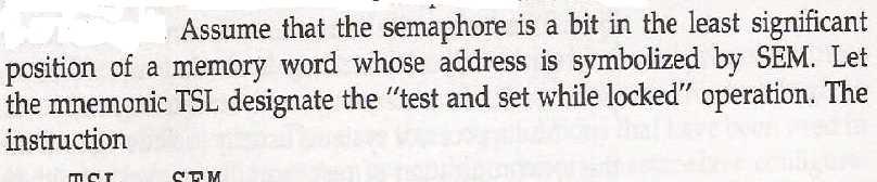
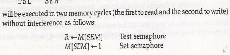
55 A semaphore can be initialized by means of test and set instruction in conjunction with a hardware lock mechanism. A hardware lock is processor generated signal that prevent other processor from using system bus as long as signal is active. Test and set instruction tests and sets semaphore and activate lock mechanism during the time that it is testing and setting it.
56
57 The last instruction in the program must be clear location SEM to 0 to released shared resource to other processor. Lock signal must be active during execution of test and set instruction. It does not have to be active once semaphore is set.
58 P1 Using binary Semaphore p1 or queue semaphore p2 P2 Busy Wait P(S) S Semaphore P(S) Critical region V(S) Shared data structure V(S) Critical region Figure. Using a semaphore to solve the mutual execution problem
59 Cache Coherence In shared memory multi-processor system it is customary to have one or two levels of cache associated with each processor. Caches in such machines require coordinated access to multiple copies as read-write data to shared data must be coordinated. This organization is essential to achieve high performance. Cache creates a problem which is known as the cache coherence problem. The cache coherence problem is: Multiple copies of the same data can exist in different caches simultaneously, and if processors are allowed to update their own copies freely, an inconsistent view of memory can result. To ensure ability of the system to execute memory instruction independently, multiple copies of the data must be identical which is called cache coherence.
60 Condition to cache Incoherence This condition arise when the processor need to share the writable data. In both policy write back and write through incoherence condition is created. Write back: Write operations are usually made only to the cache. Main memory is only updated when the corresponding cache line is flushed from the cache. Write through: All write operations are made to main memory as well as to the cache, ensuring that main memory is always valid
61 Cache Coherence In shared memory multi-processor system, processor share memory and they have local memory(part or all of which is cache). To ensure ability of the system to execute memory instruction independently, multiple copies of the data must be identical which is called cache coherence.
62 local memories
63 Cache Coherence due to Write through policy
64 Cache Coherence due to Write back policy
65 Solution using Software A simple way is to disallow to have private caches and use the common memory for shared resources. Another way is to cache only the read only data in the local cache and use the common memory for writable data. A scheme that allows writable data to reside in only one cache. A centralized global table is used to maintain details: Status of each memory block as read only (RO) or read write (RW) is stored. All local cache can store RO memory blocks. RW memory blocks are stored only in one cache that is shared by all.
66 Hardware Solution Snoopy cache controller A hardware specially designed to watch the system bus for write operation. When a word is updated in cache, main memory is also updated. Local snoopy controller watch the cache if they have the address updated. - If the copy exist, it is marked invalid. - If CPU request the same address, it is fetch from the main memory and updated in cache.
Chapter 8 : Multiprocessors
 Chapter 8 Multiprocessors 8.1 Characteristics of multiprocessors A multiprocessor system is an interconnection of two or more CPUs with memory and input-output equipment. The term processor in multiprocessor
MULTIPROCESSORS. Characteristics of Multiprocessors. Interconnection Structures. Interprocessor Arbitration
 MULTIPROCESSORS Characteristics of Multiprocessors Interconnection Structures Interprocessor Arbitration Interprocessor Communication and Synchronization Cache Coherence 2 Characteristics of Multiprocessors
Characteristics of Mult l ip i ro r ce c ssors r
 Characteristics of Multiprocessors A multiprocessor system is an interconnection of two or more CPUs with memory and input output equipment. The term processor in multiprocessor can mean either a central
4. Networks. in parallel computers. Advances in Computer Architecture
 4. Networks in parallel computers Advances in Computer Architecture System architectures for parallel computers Control organization Single Instruction stream Multiple Data stream (SIMD) All processors
1. Define Peripherals. Explain I/O Bus and Interface Modules. Peripherals: Input-output device attached to the computer are also called peripherals.
 1. Define Peripherals. Explain I/O Bus and Interface Modules. Peripherals: Input-output device attached to the computer are also called peripherals. A typical communication link between the processor and
Advanced Parallel Architecture. Annalisa Massini /2017
 Advanced Parallel Architecture Annalisa Massini - 2016/2017 References Advanced Computer Architecture and Parallel Processing H. El-Rewini, M. Abd-El-Barr, John Wiley and Sons, 2005 Parallel computing
A MULTIPROCESSOR SYSTEM. Mariam A. Salih
 A MULTIPROCESSOR SYSTEM Mariam A. Salih Multiprocessors classification. interconnection networks (INs) Mode of Operation Control Strategy switching techniques Topology BUS-BASED DYNAMIC INTERCONNECTION
Multi-Processor / Parallel Processing
 Parallel Processing: Multi-Processor / Parallel Processing Originally, the computer has been viewed as a sequential machine. Most computer programming languages require the programmer to specify algorithms
INTERCONNECTION NETWORKS LECTURE 4
 INTERCONNECTION NETWORKS LECTURE 4 DR. SAMMAN H. AMEEN 1 Topology Specifies way switches are wired Affects routing, reliability, throughput, latency, building ease Routing How does a message get from source
Pipeline and Vector Processing 1. Parallel Processing SISD SIMD MISD & MIMD
 Pipeline and Vector Processing 1. Parallel Processing Parallel processing is a term used to denote a large class of techniques that are used to provide simultaneous data-processing tasks for the purpose
Multiprocessors Interconnection Networks
 Babylon University College of Information Technology Software Department Multiprocessors Interconnection Networks By Interconnection Networks Taxonomy An interconnection network could be either static
This chapter provides the background knowledge about Multistage. multistage interconnection networks are explained. The need, objectives, research
 CHAPTER 1 Introduction This chapter provides the background knowledge about Multistage Interconnection Networks. Metrics used for measuring the performance of various multistage interconnection networks
INPUT-OUTPUT ORGANIZATION
 INPUT-OUTPUT ORGANIZATION Peripheral Devices: The Input / output organization of computer depends upon the size of computer and the peripherals connected to it. The I/O Subsystem of the computer, provides
CSCI 4717 Computer Architecture
 CSCI 4717/5717 Computer Architecture Topic: Symmetric Multiprocessors & Clusters Reading: Stallings, Sections 18.1 through 18.4 Classifications of Parallel Processing M. Flynn classified types of parallel
Physical Organization of Parallel Platforms. Alexandre David
 Physical Organization of Parallel Platforms Alexandre David 1.2.05 1 Static vs. Dynamic Networks 13-02-2008 Alexandre David, MVP'08 2 Interconnection networks built using links and switches. How to connect:
2 MARKS Q&A 1 KNREDDY UNIT-I
 2 MARKS Q&A 1 KNREDDY UNIT-I 1. What is bus; list the different types of buses with its function. A group of lines that serves as a connecting path for several devices is called a bus; TYPES: ADDRESS BUS,
Chapter 9 Multiprocessors
 ECE200 Computer Organization Chapter 9 Multiprocessors David H. lbonesi and the University of Rochester Henk Corporaal, TU Eindhoven, Netherlands Jari Nurmi, Tampere University of Technology, Finland University
INPUT/OUTPUT ORGANIZATION
 INPUT/OUTPUT ORGANIZATION Accessing I/O Devices I/O interface Input/output mechanism Memory-mapped I/O Programmed I/O Interrupts Direct Memory Access Buses Synchronous Bus Asynchronous Bus I/O in CO and
SMD149 - Operating Systems - Multiprocessing
 SMD149 - Operating Systems - Multiprocessing Roland Parviainen December 1, 2005 1 / 55 Overview Introduction Multiprocessor systems Multiprocessor, operating system and memory organizations 2 / 55 Introduction
Overview. SMD149 - Operating Systems - Multiprocessing. Multiprocessing architecture. Introduction SISD. Flynn s taxonomy
 Overview SMD149 - Operating Systems - Multiprocessing Roland Parviainen Multiprocessor systems Multiprocessor, operating system and memory organizations December 1, 2005 1/55 2/55 Multiprocessor system
INPUT/OUTPUT ORGANIZATION
 INPUT/OUTPUT ORGANIZATION Accessing I/O Devices I/O interface Input/output mechanism Memory-mapped I/O Programmed I/O Interrupts Direct Memory Access Buses Synchronous Bus Asynchronous Bus I/O in CO and
Multiprocessor Interconnection Networks- Part Three
 Babylon University College of Information Technology Software Department Multiprocessor Interconnection Networks- Part Three By The k-ary n-cube Networks The k-ary n-cube network is a radix k cube with
EE/CSCI 451: Parallel and Distributed Computation
 EE/CSCI 451: Parallel and Distributed Computation Lecture #4 1/24/2018 Xuehai Qian xuehai.qian@usc.edu http://alchem.usc.edu/portal/xuehaiq.html University of Southern California 1 Announcements PA #1
Parallel Architecture. Sathish Vadhiyar
 Parallel Architecture Sathish Vadhiyar Motivations of Parallel Computing Faster execution times From days or months to hours or seconds E.g., climate modelling, bioinformatics Large amount of data dictate
Interconnection Network. Jinkyu Jeong Computer Systems Laboratory Sungkyunkwan University
 Interconnection Network Jinkyu Jeong (jinkyu@skku.edu) Computer Systems Laboratory Sungkyunkwan University http://csl.skku.edu Topics Taxonomy Metric Topologies Characteristics Cost Performance 2 Interconnection
Multiple Processor Systems. Lecture 15 Multiple Processor Systems. Multiprocessor Hardware (1) Multiprocessors. Multiprocessor Hardware (2)
 Multiprocessors. Multiprocessor Hardware (2)") Lecture 15 Multiple Processor Systems Multiple Processor Systems Multiprocessors Multicomputers Continuous need for faster computers shared memory model message passing multiprocessor wide area distributed
Lecture 15 Multiple Processor Systems Multiple Processor Systems Multiprocessors Multicomputers Continuous need for faster computers shared memory model message passing multiprocessor wide area distributed
Chapter 18: Database System Architectures.! Centralized Systems! Client--Server Systems! Parallel Systems! Distributed Systems!
 Chapter 18: Database System Architectures! Centralized Systems! Client--Server Systems! Parallel Systems! Distributed Systems! Network Types 18.1 Centralized Systems! Run on a single computer system and
CHAPTER 6 FPGA IMPLEMENTATION OF ARBITERS ALGORITHM FOR NETWORK-ON-CHIP
 133 CHAPTER 6 FPGA IMPLEMENTATION OF ARBITERS ALGORITHM FOR NETWORK-ON-CHIP 6.1 INTRODUCTION As the era of a billion transistors on a one chip approaches, a lot of Processing Elements (PEs) could be located
Unit 3 and Unit 4: Chapter 4 INPUT/OUTPUT ORGANIZATION
 Unit 3 and Unit 4: Chapter 4 INPUT/OUTPUT ORGANIZATION Introduction A general purpose computer should have the ability to exchange information with a wide range of devices in varying environments. Computers
Computer Organization. Chapter 16
 William Stallings Computer Organization and Architecture t Chapter 16 Parallel Processing Multiple Processor Organization Single instruction, single data stream - SISD Single instruction, multiple data
Interconnection Network
 Interconnection Network Jinkyu Jeong (jinkyu@skku.edu) Computer Systems Laboratory Sungkyunkwan University http://csl.skku.edu SSE3054: Multicore Systems, Spring 2017, Jinkyu Jeong (jinkyu@skku.edu) Topics
Chapter 18 Parallel Processing
 Chapter 18 Parallel Processing Multiple Processor Organization Single instruction, single data stream - SISD Single instruction, multiple data stream - SIMD Multiple instruction, single data stream - MISD
Parallel Architectures
 Parallel Architectures CPS343 Parallel and High Performance Computing Spring 2018 CPS343 (Parallel and HPC) Parallel Architectures Spring 2018 1 / 36 Outline 1 Parallel Computer Classification Flynn s
SIDDHARTH GROUP OF INSTITUTIONS :: PUTTUR Siddharth Nagar, Narayanavanam Road QUESTION BANK (DESCRIPTIVE) UNIT-I
 UNIT-I") SIDDHARTH GROUP OF INSTITUTIONS :: PUTTUR Siddharth Nagar, Narayanavanam Road 517583 QUESTION BANK (DESCRIPTIVE) Subject with Code : CO (16MC802) Year & Sem: I-MCA & I-Sem Course & Branch: MCA Regulation:
SIDDHARTH GROUP OF INSTITUTIONS :: PUTTUR Siddharth Nagar, Narayanavanam Road 517583 QUESTION BANK (DESCRIPTIVE) Subject with Code : CO (16MC802) Year & Sem: I-MCA & I-Sem Course & Branch: MCA Regulation:
TDT Appendix E Interconnection Networks
 TDT 4260 Appendix E Interconnection Networks Review Advantages of a snooping coherency protocol? Disadvantages of a snooping coherency protocol? Advantages of a directory coherency protocol? Disadvantages
CS152 Computer Architecture and Engineering Lecture 20: Busses and OS s Responsibilities. Recap: IO Benchmarks and I/O Devices
 CS152 Computer Architecture and Engineering Lecture 20: ses and OS s Responsibilities April 7, 1995 Dave Patterson (patterson@cs) and Shing Kong (shing.kong@eng.sun.com) Slides available on http://http.cs.berkeley.edu/~patterson
PART A (22 Marks) 2. a) Briefly write about r's complement and (r-1)'s complement. [8] b) Explain any two ways of adding decimal numbers.
![PART A (22 Marks) 2. a) Briefly write about r's complement and (r-1)'s complement. [8] b) Explain any two ways of adding decimal numbers.](/thumbs/96/128058841.jpg "PART A (22 Marks) 2. a) Briefly write about r's complement and (r-1)'s complement. [8] b) Explain any two ways of adding decimal numbers.") Set No. 1 IV B.Tech I Semester Supplementary Examinations, March - 2017 COMPUTER ARCHITECTURE & ORGANIZATION (Common to Electronics & Communication Engineering and Electronics & Time: 3 hours Max. Marks:
Set No. 1 IV B.Tech I Semester Supplementary Examinations, March - 2017 COMPUTER ARCHITECTURE & ORGANIZATION (Common to Electronics & Communication Engineering and Electronics & Time: 3 hours Max. Marks:
Readings, exercises: Chapter 11 (Due: 10/4) Homework keys Study group(s) Prelim 1 10/6!
 Homework keys Study group(s) Prelim 1 10/6!") Homework Readings, exercises: Chapter 11 (Due: 10/4) Homework keys Study group(s) Prelim 1 10/6! Copyright c 2002 2017 UMaine School of Computing and Information S 1 / 20 COS 140: Foundations of : Daisy
Homework Readings, exercises: Chapter 11 (Due: 10/4) Homework keys Study group(s) Prelim 1 10/6! Copyright c 2002 2017 UMaine School of Computing and Information S 1 / 20 COS 140: Foundations of : Daisy
Top-Level View of Computer Organization
 Top-Level View of Computer Organization Bởi: Hoang Lan Nguyen Computer Component Contemporary computer designs are based on concepts developed by John von Neumann at the Institute for Advanced Studies
Chapter 20: Database System Architectures
 Chapter 20: Database System Architectures Chapter 20: Database System Architectures Centralized and Client-Server Systems Server System Architectures Parallel Systems Distributed Systems Network Types
Interconnection networks
 Interconnection networks When more than one processor needs to access a memory structure, interconnection networks are needed to route data from processors to memories (concurrent access to a shared memory
CSC630/CSC730: Parallel Computing
 CSC630/CSC730: Parallel Computing Parallel Computing Platforms Chapter 2 (2.4.1 2.4.4) Dr. Joe Zhang PDC-4: Topology 1 Content Parallel computing platforms Logical organization (a programmer s view) Control
Chapter 7 : Input-Output Organization
 Chapter 7 Input-Output organization 7.1 Peripheral devices In addition to the processor and a set of memory modules, the third key element of a computer system is a set of input-output subsystem referred
06-Dec-17. Credits:4. Notes by Pritee Parwekar,ANITS 06-Dec-17 1
 Credits:4 1 Understand the Distributed Systems and the challenges involved in Design of the Distributed Systems. Understand how communication is created and synchronized in Distributed systems Design and
Scalable Cache Coherence
 Scalable Cache Coherence [ 8.1] All of the cache-coherent systems we have talked about until now have had a bus. Not only does the bus guarantee serialization of transactions; it also serves as convenient
Lecture 9: MIMD Architectures
 Lecture 9: MIMD Architectures Introduction and classification Symmetric multiprocessors NUMA architecture Clusters Zebo Peng, IDA, LiTH 1 Introduction A set of general purpose processors is connected together.
Blog - https://anilkumarprathipati.wordpress.com/
 Input-Output organization 1. Peripheral Devices The input-output subsystem of a computer, referred to as I/O, provides an efficient mode of communication between the central system and the outside environment.
Bus System. Bus Lines. Bus Systems. Chapter 8. Common connection between the CPU, the memory, and the peripheral devices.
 Bus System Chapter 8 CSc 314 T W Bennet Mississippi College 1 CSc 314 T W Bennet Mississippi College 3 Bus Systems Common connection between the CPU, the memory, and the peripheral devices. One device
Embedded Systems: Hardware Components (part II) Todor Stefanov
 Todor Stefanov") Embedded Systems: Hardware Components (part II) Todor Stefanov Leiden Embedded Research Center, Leiden Institute of Advanced Computer Science Leiden University, The Netherlands Outline Generic Embedded
Embedded Systems: Hardware Components (part II) Todor Stefanov Leiden Embedded Research Center, Leiden Institute of Advanced Computer Science Leiden University, The Netherlands Outline Generic Embedded
SEMICON Solutions. Bus Structure. Created by: Duong Dang Date: 20 th Oct,2010
 SEMICON Solutions Bus Structure Created by: Duong Dang Date: 20 th Oct,2010 Introduction Buses are the simplest and most widely used interconnection networks A number of modules is connected via a single
SRI VIDYA COLLEGE OF ENGINEERING AND TECHNOLOGY,VIRUDHUNAGAR
 Year/sem: 02/04 Academic Year: 2014-2015 (even) UNIT II THE 8086 SYSTEM BUS STRUCTURE PART A 1. What are the three groups of signals in 8086? The 8086 signals are categorized in three groups. They are:
Lecture 13. Storage, Network and Other Peripherals
 Lecture 13 Storage, Network and Other Peripherals 1 I/O Systems Processor interrupts Cache Processor & I/O Communication Memory - I/O Bus Main Memory I/O Controller I/O Controller I/O Controller Disk Disk
10 Parallel Organizations: Multiprocessor / Multicore / Multicomputer Systems
 1 License: http://creativecommons.org/licenses/by-nc-nd/3.0/ 10 Parallel Organizations: Multiprocessor / Multicore / Multicomputer Systems To enhance system performance and, in some cases, to increase
Lecture 9: MIMD Architectures
 Lecture 9: MIMD Architectures Introduction and classification Symmetric multiprocessors NUMA architecture Clusters Zebo Peng, IDA, LiTH 1 Introduction MIMD: a set of general purpose processors is connected
Instruction Register. Instruction Decoder. Control Unit (Combinational Circuit) Control Signals (These signals go to register) The bus and the ALU
 Control Signals (These signals go to register) The bus and the ALU") Hardwired and Microprogrammed Control For each instruction, the control unit causes the CPU to execute a sequence of steps correctly. In reality, there must be control signals to assert lines on various
Hardwired and Microprogrammed Control For each instruction, the control unit causes the CPU to execute a sequence of steps correctly. In reality, there must be control signals to assert lines on various
3. Which of the following is volatile? [ ] A) Bubble memory B) RAM C) ROM D) Magneticdisk
![3. Which of the following is volatile? [ ] A) Bubble memory B) RAM C) ROM D) Magneticdisk](/thumbs/89/98061154.jpg "3. Which of the following is volatile? [ ] A) Bubble memory B) RAM C) ROM D) Magneticdisk") Code No: 05210505 Set No. 1 JAWAHARLAL NEHRU TECHNOLOGICAL UNIVERSITY HYDERABAD III B.Tech. II Sem. II Mid-Term Examinations, April 2009 COMPUTER ORGANIZATION Objective Exam Name: Hall Ticket No. Answer
Code No: 05210505 Set No. 1 JAWAHARLAL NEHRU TECHNOLOGICAL UNIVERSITY HYDERABAD III B.Tech. II Sem. II Mid-Term Examinations, April 2009 COMPUTER ORGANIZATION Objective Exam Name: Hall Ticket No. Answer
PIPELINE AND VECTOR PROCESSING
 PIPELINE AND VECTOR PROCESSING PIPELINING: Pipelining is a technique of decomposing a sequential process into sub operations, with each sub process being executed in a special dedicated segment that operates
Organisasi Sistem Komputer
 LOGO Organisasi Sistem Komputer OSK 14 Parallel Processing Pendidikan Teknik Elektronika FT UNY Multiple Processor Organization Single instruction, single data stream - SISD Single instruction, multiple
6 Direct Memory Access (DMA)
") 1 License: http://creativecommons.org/licenses/by-nc-nd/3.0/ 6 Direct Access (DMA) DMA technique is used to transfer large volumes of data between I/O interfaces and the memory. Example: Disk drive controllers,
1 License: http://creativecommons.org/licenses/by-nc-nd/3.0/ 6 Direct Access (DMA) DMA technique is used to transfer large volumes of data between I/O interfaces and the memory. Example: Disk drive controllers,
DISTRIBUTED EMBEDDED ARCHITECTURES
 DISTRIBUTED EMBEDDED ARCHITECTURES A distributed embedded system can be organized in many different ways, but its basic units are the Processing Elements (PE) and the network as illustrated in Figure.
Parallel Systems Prof. James L. Frankel Harvard University. Version of 6:50 PM 4-Dec-2018 Copyright 2018, 2017 James L. Frankel. All rights reserved.
 Parallel Systems Prof. James L. Frankel Harvard University Version of 6:50 PM 4-Dec-2018 Copyright 2018, 2017 James L. Frankel. All rights reserved. Architectures SISD (Single Instruction, Single Data)
CS575 Parallel Processing
 CS575 Parallel Processing Lecture three: Interconnection Networks Wim Bohm, CSU Except as otherwise noted, the content of this presentation is licensed under the Creative Commons Attribution 2.5 license.
Introduction to Multiprocessors (Part I) Prof. Cristina Silvano Politecnico di Milano
 Prof. Cristina Silvano Politecnico di Milano") Introduction to Multiprocessors (Part I) Prof. Cristina Silvano Politecnico di Milano Outline Key issues to design multiprocessors Interconnection network Centralized shared-memory architectures Distributed
Introduction to Multiprocessors (Part I) Prof. Cristina Silvano Politecnico di Milano Outline Key issues to design multiprocessors Interconnection network Centralized shared-memory architectures Distributed
Interconnection Network
 Interconnection Network Recap: Generic Parallel Architecture A generic modern multiprocessor Network Mem Communication assist (CA) $ P Node: processor(s), memory system, plus communication assist Network
Concepts of Distributed Systems 2006/2007
 Concepts of Distributed Systems 2006/2007 Introduction & overview Johan Lukkien 1 Introduction & overview Communication Distributed OS & Processes Synchronization Security Consistency & replication Programme
Buses. Disks PCI RDRAM RDRAM LAN. Some slides adapted from lecture by David Culler. Pentium 4 Processor. Memory Controller Hub.
 es > 100 MB/sec Pentium 4 Processor L1 and L2 caches Some slides adapted from lecture by David Culler 3.2 GB/sec Display Memory Controller Hub RDRAM RDRAM Dual Ultra ATA/100 24 Mbit/sec Disks LAN I/O Controller
Buses. Maurizio Palesi. Maurizio Palesi 1
 Buses Maurizio Palesi Maurizio Palesi 1 Introduction Buses are the simplest and most widely used interconnection networks A number of modules is connected via a single shared channel Microcontroller Microcontroller
Chapter 6. I/O issues
 Computer Architectures Chapter 6 I/O issues Tien-Fu Chen National Chung Cheng Univ Chap6 - Input / Output Issues I/O organization issue- CPU-memory bus, I/O bus width A/D multiplex Split transaction Synchronous
Lecture 9: MIMD Architecture
 Lecture 9: MIMD Architecture Introduction and classification Symmetric multiprocessors NUMA architecture Cluster machines Zebo Peng, IDA, LiTH 1 Introduction MIMD: a set of general purpose processors is
CS 6143 COMPUTER ARCHITECTURE II SPRING 2014
 CS 6143 COMPUTER ARCHITECTURE II SPRING 2014 DUE : April 9, 2014 HOMEWORK IV READ : - Related portions of Chapter 5 and Appendces F and I of the Hennessy book - Related portions of Chapter 1, 4 and 6 of
Basic Processing Unit: Some Fundamental Concepts, Execution of a. Complete Instruction, Multiple Bus Organization, Hard-wired Control,
 UNIT - 7 Basic Processing Unit: Some Fundamental Concepts, Execution of a Complete Instruction, Multiple Bus Organization, Hard-wired Control, Microprogrammed Control Page 178 UNIT - 7 BASIC PROCESSING
Unit 9 : Fundamentals of Parallel Processing
 Unit 9 : Fundamentals of Parallel Processing Lesson 1 : Types of Parallel Processing 1.1. Learning Objectives On completion of this lesson you will be able to : classify different types of parallel processing
Chapter 3. Top Level View of Computer Function and Interconnection. Yonsei University
 Chapter 3 Top Level View of Computer Function and Interconnection Contents Computer Components Computer Function Interconnection Structures Bus Interconnection PCI 3-2 Program Concept Computer components
Design with Microprocessors
 Design with Microprocessors Year III Computer Sci. English 1-st Semester Lecture 14: 8086/8088-BASED MULTIPROCESSOR SYSTEMS 8086 in maximum mode (#MX=0) 8288 Command Decode Definition 8086 in maximum mode
 UNIT II SYSTEM BUS STRUCTURE 1. Differentiate between minimum and maximum mode 2. Give any four pin definitions for the minimum mode. 3. What are the pins that are used to indicate the type of transfer
EE108B Lecture 17 I/O Buses and Interfacing to CPU. Christos Kozyrakis Stanford University
 EE108B Lecture 17 I/O Buses and Interfacing to CPU Christos Kozyrakis Stanford University http://eeclass.stanford.edu/ee108b 1 Announcements Remaining deliverables PA2.2. today HW4 on 3/13 Lab4 on 3/19
Non-Uniform Memory Access (NUMA) Architecture and Multicomputers
 Architecture and Multicomputers") Non-Uniform Memory Access (NUMA) Architecture and Multicomputers Parallel and Distributed Computing Department of Computer Science and Engineering (DEI) Instituto Superior Técnico February 29, 2016 CPD
Non-Uniform Memory Access (NUMA) Architecture and Multicomputers Parallel and Distributed Computing Department of Computer Science and Engineering (DEI) Instituto Superior Técnico February 29, 2016 CPD
CS 571 Operating Systems. Midterm Review. Angelos Stavrou, George Mason University
 CS 571 Operating Systems Midterm Review Angelos Stavrou, George Mason University Class Midterm: Grading 2 Grading Midterm: 25% Theory Part 60% (1h 30m) Programming Part 40% (1h) Theory Part (Closed Books):
Chapter 4. MARIE: An Introduction to a Simple Computer. Chapter 4 Objectives. 4.1 Introduction. 4.2 CPU Basics
 Chapter 4 Objectives Learn the components common to every modern computer system. Chapter 4 MARIE: An Introduction to a Simple Computer Be able to explain how each component contributes to program execution.
Multiprocessor Cache Coherency. What is Cache Coherence?
 Multiprocessor Cache Coherency CS448 1 What is Cache Coherence? Two processors can have two different values for the same memory location 2 1 Terminology Coherence Defines what values can be returned by
Chapter 5 Input/Output Organization. Jin-Fu Li Department of Electrical Engineering National Central University Jungli, Taiwan
 Chapter 5 Input/Output Organization Jin-Fu Li Department of Electrical Engineering National Central University Jungli, Taiwan Outline Accessing I/O Devices Interrupts Direct Memory Access Buses Interface
Lecture 23 Database System Architectures
 CMSC 461, Database Management Systems Spring 2018 Lecture 23 Database System Architectures These slides are based on Database System Concepts 6 th edition book (whereas some quotes and figures are used
CSE Introduction to Parallel Processing. Chapter 4. Models of Parallel Processing
 Dr Izadi CSE-4533 Introduction to Parallel Processing Chapter 4 Models of Parallel Processing Elaborate on the taxonomy of parallel processing from chapter Introduce abstract models of shared and distributed
Module 5 Introduction to Parallel Processing Systems
 Module 5 Introduction to Parallel Processing Systems 1. What is the difference between pipelining and parallelism? In general, parallelism is simply multiple operations being done at the same time.this
Lecture 7: Parallel Processing
 Lecture 7: Parallel Processing Introduction and motivation Architecture classification Performance evaluation Interconnection network Zebo Peng, IDA, LiTH 1 Performance Improvement Reduction of instruction
Types of Parallel Computers
 slides1-22 Two principal types: Types of Parallel Computers Shared memory multiprocessor Distributed memory multicomputer slides1-23 Shared Memory Multiprocessor Conventional Computer slides1-24 Consists
SHARED MEMORY VS DISTRIBUTED MEMORY
 OVERVIEW Important Processor Organizations 3 SHARED MEMORY VS DISTRIBUTED MEMORY Classical parallel algorithms were discussed using the shared memory paradigm. In shared memory parallel platform processors
UNIT 1 MULTIPROCESSOR SYSTEMS
 UNIT 1 MULTIPROCESSOR SYSTEMS Multiprocessor Systems Structure Page Nos. 1.0 Introduction 5 1.1 Objectives 6 1.2 Multiprocessing and Processor Coupling 6 1.3 Multiprocessor Interconnections 6 1.3.1 Bus-oriented
A More Sophisticated Snooping-Based Multi-Processor
 Lecture 16: A More Sophisticated Snooping-Based Multi-Processor Parallel Computer Architecture and Programming CMU 15-418/15-618, Spring 2014 Tunes The Projects Handsome Boy Modeling School (So... How
UNIT:2. Process Management
 1 UNIT:2 Process Management SYLLABUS 2.1 Process and Process management i. Process model overview ii. Programmers view of process iii. Process states 2.2 Process and Processor Scheduling i Scheduling Criteria
Non-Uniform Memory Access (NUMA) Architecture and Multicomputers
 Architecture and Multicomputers") Non-Uniform Memory Access (NUMA) Architecture and Multicomputers Parallel and Distributed Computing Department of Computer Science and Engineering (DEI) Instituto Superior Técnico September 26, 2011 CPD
Non-Uniform Memory Access (NUMA) Architecture and Multicomputers Parallel and Distributed Computing Department of Computer Science and Engineering (DEI) Instituto Superior Técnico September 26, 2011 CPD
HANDLING MULTIPLE DEVICES
 HANDLING MULTIPLE DEVICES Let us now consider the situation where a number of devices capable of initiating interrupts are connected to the processor. Because these devices are operationally independent,
Design and Simulation of Router Using WWF Arbiter and Crossbar
 Design and Simulation of Router Using WWF Arbiter and Crossbar M.Saravana Kumar, K.Rajasekar Electronics and Communication Engineering PSG College of Technology, Coimbatore, India Abstract - Packet scheduling
Process Synchroniztion Mutual Exclusion & Election Algorithms
 Process Synchroniztion Mutual Exclusion & Election Algorithms Paul Krzyzanowski Rutgers University November 2, 2017 1 Introduction Process synchronization is the set of techniques that are used to coordinate
Page 1. Cache Coherence
 Page 1 Cache Coherence 1 Page 2 Memory Consistency in SMPs CPU-1 CPU-2 A 100 cache-1 A 100 cache-2 CPU-Memory bus A 100 memory Suppose CPU-1 updates A to 200. write-back: memory and cache-2 have stale
Operating System Review Part
 Operating System Review Part CMSC 602 Operating Systems Ju Wang, 2003 Fall Virginia Commonwealth University Review Outline Definition Memory Management Objective Paging Scheme Virtual Memory System and
Multiprocessor Systems Continuous need for faster computers Multiprocessors: shared memory model, access time nanosec (ns) Multicomputers: message pas
 Multicomputers: message pas") Multiple processor systems 1 Multiprocessor Systems Continuous need for faster computers Multiprocessors: shared memory model, access time nanosec (ns) Multicomputers: message passing multiprocessor, access
Multiple processor systems 1 Multiprocessor Systems Continuous need for faster computers Multiprocessors: shared memory model, access time nanosec (ns) Multicomputers: message passing multiprocessor, access
Three parallel-programming models
 Three parallel-programming models Shared-memory programming is like using a bulletin board where you can communicate with colleagues. essage-passing is like communicating via e-mail or telephone calls.
Multiprocessor and Real- Time Scheduling. Chapter 10
 Multiprocessor and Real- Time Scheduling Chapter 10 Classifications of Multiprocessor Loosely coupled multiprocessor each processor has its own memory and I/O channels Functionally specialized processors
Operating Systems, Fall Lecture 9, Tiina Niklander 1
 Multiprocessor Systems Multiple processor systems Ch 8.1 8.3 1 Continuous need for faster computers Multiprocessors: shared memory model, access time nanosec (ns) Multicomputers: message passing multiprocessor,