24-Port 10/100Mbps with 2-Gigabit Web Smart Ethernet Switch
|
|
|
- Audra Wood
- 5 years ago
- Views:
Transcription

1 User's Manual FGSW-2402VS FGSW-2620VSF FGSW-2624SF 24-Port 10/100Mbps with 2-Gigabit Web Smart Ethernet Switch - 1 -
2 Trademarks Copyright PLANET Technology Corp Contents subject to revision without prior notice. PLANET is a registered trademark of PLANET Technology Corp. All other trademarks belong to their respective owners. Disclaimer PLANET Technology does not warrant that the hardware will work properly in all environments and applications, and makes no warranty and representation, either implied or expressed, with respect to the quality, performance, merchantability, or fitness for a particular purpose. PLANET has made every effort to ensure that this User s Manual is accurate; PLANET disclaims liability for any inaccuracies or omissions that may have occurred. Information in this User s Manual is subject to change without notice and does not represent a commitment on the part of PLANET. PLANET assumes no responsibility for any inaccuracies that may be contained in this User s Manual. PLANET makes no commitment to update or keep current the information in this User s Manual, and reserves the right to make improvements to this User s Manual and/or to the products described in this User s Manual, at any time without notice. If you find information in this manual that is incorrect, misleading, or incomplete, we would appreciate your comments and suggestions. FCC Warning This equipment has been tested and found to comply with the limits for a Class A digital device, pursuant to Part 15 of the FCC Rules. These limits are designed to provide reasonable protection against harmful interference when the equipment is operated in a commercial environment. This equipment generates, uses, and can radiate radio frequency energy and, if not installed and used in accordance with the Instruction manual, may cause harmful interference to radio communications. Operation of this equipment in a residential area is likely to cause harmful interference in which case the user will be required to correct the interference at his own expense. CE Mark Warning This is a Class A product. In a domestic environment, this product may cause radio interference, in which case the user may be required to take adequate measures. WEEE Warning To avoid the potential effects on the environment and human health as a result of the presence of hazardous substances in electrical and electronic equipment, end users of electrical and electronic equipment should understand the meaning of the crossed-out wheeled bin symbol. Do not dispose of WEEE as unsorted municipal waste and have to collect such WEEE separately. Revision PLANET 24-Port 10/100Mbps with 2-Gigabit Web Smart Ethernet Switch User's Manual FOR MODELS: FGSW-2402VS/FGSW-2620VSF REVISION: 2.1(JANUARY.2007) Part No.: 2080-A
3 TABLE OF CONTENTS 1. INTRODUCTION CHECKLIST ABOUT THE SWITCH FEATURES SPECIFICATION HARDWARE DESCRIPTION FRONT PANEL REAR PANEL HARDWARE INSTALLATION Desktop Installation Rack Mounting Installing the SFP transceiver SWITCH MANAGEMENT OVERVIEW MANAGEMENT METHOD Web Management LOGGING ON TO THE WEB SMART SWITCH WEB MANAGEMENT LOGIN IN TO THE SWITCH PORT STATUS PORT CONFIGURATION TRUNK CONFIGURATION VLAN CONFIGURATION Enable port-based VLAN function and add a port-based VLAN group Edit existence port-based VLAN group Delete existence port-based VLAN group Disable port-based VLAN function Enable 802.1Q VLAN function and add a new VLAN group Configure Advanced 802.1Q VLAN Setting Edit existence 802.1Q VLAN group Delete existence 802.1Q VLAN group PORT MONITORING QOS CONFIGURATION PORT COUNTERS ACCESS CONTROL LIST WEB SMART FUNCTION MISC OPERATION Switch Configuration TFTP Firmware Upgrade Password Setting IP Configuration Factory Default Reboot System System Information LOGOUT SWITCH OPERATION ADDRESS TABLE LEARNING FORWARDING & FILTERING STORE-AND-FORWARD AUTO-NEGOTIATION TROUBLESHOOTING APPENDIX A - NETWORKING CONNECTION A.1 SWITCH S RJ-45 PIN ASSIGNMENTS...74 A.2 RJ-45 CABLE PIN ASSIGNMENT...74 APPENDIX B - ACCESS CONTROL LIST APPLICATION GUIDE Before the ACL Configure...77 Case 1: Deny specific Source IP Address Host...78 Case 2: Deny specific Source IP Address Class C...80 Case 3: Deny IP packets to specific Class C network...82 Case 4: Deny specific VLAN packets
4 Case 5: Deny Specify Protocol HTTP / Case 6: Deny Specify Protocol SMTP
5 1. INTRODUCTION 1.1 Checklist Check the contents of your package for following parts: The Web Smart Switch x1 User's manual CD x1 Quick installation guide x1 Power cord x 1 Rubber feet x 4 Rack mount accessory x 1 If any of these pieces are missing or damaged, please contact your dealer immediately, if possible, retain the carton including the original packing material, and use them against to repack the product in case there is a need to return it to us for repair. In the following section, the term Web Smart Switch means the Switch devices, ie. FGSW-2402VS, FGSW-2620VSF and FGSW-2624SF; term of switch can be any third switches. 1.2 About the Switch The FGSW-2402VS offers 24 10/100Mbps Fast Ethernet ports with 2 open slots (port25, 26). The two open slots can be installed by optionally two of 1000Base-T port, 100Base-FX, or 1000Base- SX/LX fiber-optic interfaces. The distance can be extended from 100 meters (TP), 2 kilometers (Multi-mode, ST or SC), up to 15 kilometers (Single-mode, SC). The FGSW-2620VSF provides 24 10/100Mbps Fast Ethernet ports and 2 Gigabit TP/SFP combo ports. The FGSW-2624SF provides Base-FX Fast Ethernet ports and 2 Gigabit TP/SFP combo ports. The two Gigabit ports of FGSW-2620VSF and FGSW-2624SFeither can be 1000Base-T for 10/100/1000Mbps or 1000Base-SX/LX through SFP (Small Factor Pluggable) interface. The distance can be extended from 100 meters (TP), 550 meters (Multi-mode fiber), up to above 10/50/70/120 kilometers (Single-mode fiber). Both Web Smart Switches are equipped with non-blocking 8.8Gbps backplane greatly simplifies the tasks of upgrading your LAN to cater for increased bandwidth demands. For efficient management, the Web Smart Switch is equipped with web interface. The two Web Smart Switches can be programmed for basic switch management functions such as port speed configuration, Port Trunking, IEEE 802.1Q Tag-Based VLAN and Port-based VLAN, Port Mirroring, QoS, bandwidth control, Access Control list and Misc Configuration. The Web Smart Switch provides port-based VLAN (including overlapping). The VLAN groups allowed on the 2 Web Smart Switches will be maximally up to 26 for port-based VLAN. Via supporting port trunking, the Web Smart Switch allows the operation of a high-speed trunk combining multiple ports. The Web Smart Switch provides seven groups of up to 8-ports for trunking, and it supports fail-over as well. With its Auto-Negotiation capability, all the RJ-45/STP ports of Web Smart Switch can be configured to speeds of 10/20Mbps or 100/200Mbps automatically. In addition, the product is equipped with the MDI/MDI-X auto detection for easily plug and play connection, regardless of cabling types-straight through or crossover
6 1.3 Features Complies with the IEEE 802.3, IEEE 802.3u, IEEE 802.3z and IEEE 802.3ab Gigabit Ethernet standard 24-Port 10/100 Mbps Fast Ethernet Switch 2 open slots for 1000Base-T and 100Base-FX, 1000Base-SX/LX fiber-optic interface with various connection media and distances (FGSW-2420VS) 2-Port Gigabit TP/SFP combo ports( FGSW-2620VSF) Each Switching ports support auto-negotiation-10/20, 100/200Mbps supported Auto-MDI/MDI-X detection on each RJ-45 port Prevents packet loss with back pressure (half-duplex) and 802.3x PAUSE frame flow control (full- duplex) High performance Store and Forward architecture, broadcast storm control, runt/crc filtering eliminates erroneous packets to optimize the network bandwidth 8K MAC address table, automatic source address learning and ageing 512K Bytes packet buffers Web interface for Switch basic management and setup Support IEEE 802.1Q Tagged VLAN Support up to 26 port-based VLAN groups Support up to 7 Trunk groups, each trunk for up to maximum 8 port with 800Mbps bandwidth Port mirroring allows monitoring of the traffic across any port in real time Support QoS and bandwidth control on each port Supports Access Control List function 19-inch rack mount size Internal full-range power supply suitable for worldwide use EMI standards comply with FCC, CE class A 1.4 Specification Product FGSW-2402VS FGSW-2620VSF FGSW-2624SF Hardware Specification 10/100Mbps Ports 24 10/ 100Base-TX RJ-45 Auto-MDI/MDI-X ports Base-FX Ports Base-FX Module Slots Switch Processing Scheme 2 open slots for 1000Base-T and 100Base-FX, 1000Base-SX/LX fiber -optic interface Store-and-forward 2 Gigabit TP/SFP combo ports Throughput (packet per second) 6.547Mpps Switch fabric Address Table Share data Buffer Flow Control 8.8Gbps 8K entries 512K Bytes Back pressure for half duplex, IEEE 802.3x Pause Frame for full duplex Dimensions 440 x 120 x 44 mm, 1U height 440 x 220 x
7 Weight 1.87kg 1.85kg 2.6kg Power Requirement Power Consumption / Dissipation Temperature Humidity Operating: Smart function System Configuration Port Status 100~240V AC, Hz 13.5 Watts maximum / 46 BTU/hr maximum Operating: 0~50 degree C, Storage -40~70 degree C 10% to 90%, Storage: 5% to 95% (Non-condensing) Web interface Display per port s disable/enable status, per port s link status and speed duplex mode. Flow control status 5 watts (without SFP) 23.1 watts maximum / 73 BTU Port Configuration Trunk Configuration VLAN Configuration Port Monitoring QoS Configuration Port counters Access Control List Per port disable/enable, Auto-negotiation disable/enable. 10/100Mbps full and half duplex mode selection. Flow control disable/enable and bandwidth control on each port Support 7 groups of 8-Port trunk support Maximum up to 26 VLAN groups for both Port-based VLAN and 802.1Q VLAN One Mirroring port to monitor one mirrored port. The monitor modes are RX, TX and RX & TX IEEE 802.1p QoS on each port Display detail traffic counters on each port Supports up to 16 Access Control list group Standards Conformance Regulation Compliance Standards Compliance FCC Part 15 Class A, CE IEEE (Ethernet) IEEE 802.3u (Fast Ethernet) IEEE 802.3ab(Gigabit Ethernet) IEEE 802.3z(Gigabit Ethernet) IEEE 802.3x (Full-duplex flow control) IEEE 802.1p Priority QoS IEEE 802.1Q Tagged VLAN - 7 -
8 2. HARDWARE DESCRIPTION This product provides three different running speeds 10Mbps, 100Mbps and 1000Mbps in the same Web Smart Switch and automatically distinguishes the speed of incoming connection. This section describes the hardware features of Web Smart Switch. For easier management and control of the Web Smart Switch, familiarize yourself with its display indicators, and ports. Front panel illustrations in this chapter display the unit LED indicators. Before connecting any network device to the Web Smart Switch, read this chapter carefully. 2.1 Front Panel The Front Panel of the Web Smart Ethernet Switch consists of 24x Auto-Sensing 10/100Mbps Ethernet RJ-45 Ports, the FGSW-2402VS provide two open slots can be installed by optionally two of 1000Base-T port, 100Base-FX, or 1000Base- SX/LX fiber-optic interfaces. The FGSW-2620VSF provides 2 Gigabit TP/SFP combo ports either can be 1000Base-T for 10/100/1000Mbps or 1000Base-SX/LX through SFP (Small Factor Pluggable) interface. For the Fiber switch FGSW-2624SF, it provides Base-FX Fast Ethernet ports and 2 Gigabit TP/SFP combo ports. The LED Indicators are also located on the front panel of the Web Smart Switch. Figure 2-1: FGSW-2402VS Switch front panel Figure 2-2: FGSW-2620VSF Switch front panel Figure 2-3: FGSW-2624SF Switch front panel LED indicators System LED Color Function PWR Green Lights to indicate that the Switch has power. Per 10/100Mbps port LED Color Function LNK/ACT Green Lights to indicate the link through that port is successfully established. 100 Orange Lights to indicate the port is running in 100Mbps speed
9 Per 10/100/1000Base-T port /SFP interfaces (FGSW-2620VSF only) LED Color Function Lit: indicate that the port is operating at 1000Mbps. LNK/ACT 1000 LNK/ACT 100 FDX Green Green Green Off: indicate that the port is operating at 10Mbps or 100Mbps. Blink: indicate that the switch is actively sending or receiving data over that port. Lit: indicate that the port is operating at 100Mbps. Off: indicate that the port is operating at 10Mbps or 1000Mbps. Blink: indicate that the switch is actively sending or receiving data over that port. Lit: indicate that the port is operating at full-duplex mode. Off: indicate that the port is operating at half-duplex mode. Per 100Base-FX port (FGSW-2624SF only) LED Color Function Lit: indicate that the port is operating at 100Mbps. LNK/ACT Green Off: indicate that the port is link down Blink: indicate that the switch is actively sending or receiving data over that port. Notice: 1. Press the RESET button once. The Web Smart Switch will reboot automatically. 2. Press the RESET button for 5 seconds. The Web Smart Switch will back to the factory default mode; the entire configuration will be erased. 3. The FGSW-2402VSv2 must work with MII-V series module for 100Base-FX fiber connection. 4. The 2 Gigabit TP/SFP combo ports are shared with port 25/26 of FGSW-2620VSF/ FGSW-2624SF.Either of them can operate at the same time. 2.2 Rear Panel The rear panel of the Web Smart Switch indicates an AC inlet power socket, which accepts input power from 100 to 240VAC, 50-60Hz. Figure 2-4: FGSW-2402VS/FGSW-2620VSF Switch rear panel ON OFF POWER Figure 2-5: FGSW-2624SF Switch rear panel Power Notice: 1. The device is a power-required device, it means, it will not work till it is powered. If your networks should active all the time, please consider using UPS (Uninterrupted Power Supply) for your device. It will prevent you from network data loss or network downtime

10 2. In some area, installing a surge suppression device may also help to protect your Web Smart Switch from being damaged by unregulated surge or current to the Web Smart Switch. 2.3 Hardware Installation This part describes how to install your Web Smart Ethernet Switch and make connections to the Switch. Please read the following topics and perform the proce dures in the order being presented. To install your Web Smart Switch on a desktop or shelf, simply completed the following steps Desktop Installation To install Web Smart Switch on a desktop or shelf, simply completed the following steps: Step 1: Attached the rubber feet to the recessed areas on the bottom of the Web Smart Switch. Step 2: Place the Web Smart Switch on a desktop or shelf near an AC power source. Step 3: Keep enough ventilation space between the Web Smart Switch and the surrounding objects. Notice: When choosing a location, please keep in mind the environmental restrictions discussed in Chapter 1, Section 4, Specification. Step 4: Connect your Switch to network devices. A. Connect one end of a standard network cable to the 10/100 RJ-45 ports on the front of the Web Smart Switch. B. Connect the other end of the cable to the network devices such as printer servers, workstations or routers etc. Connection to the Web Smart Switch requires UTP Category 5 network cabling with RJ-45 tips. For Notice: more information, please see the Cabling Specification in Appendix A. Step 5: Supply power to the Web Smart Switch. A. Connect one end of the power cable to the Web Smart Switch. B. Connect the power plug of the power cable to a standard wall outlet then power on the Web Smart Switch. When the Web Smart Switch receives power, the Power LED should remain solid Green Rack Mounting To install the Web Smart Switch in a 19-inch standard rack, follow the instructions described below. Step 1: Place your Web Smart Switch on a hard flat surface, with the front panel positioned towards your front side. Step 2: Attach a rack-mount bracket to each side of the Web Smart Switch with supplied screws attached to the package. Figure 2-6 shows how to attach brackets to one side of the Web Smart Switch. Figure 2-6 Attaching the brackets to the Web Smart Switch Caution: You must use the screws supplied with the mounting brackets. Damage caused to the parts by using incorrect screws would invalidate your warranty


11 Step 3: Secure the brackets tightly. Step 4: Follow the same steps to attach the second bracket to the opposite side. Step 5: After the brackets are attached to the Web Smart Switch, use suitable screws to securely attach the brackets to the rack, as shown in Figure 2-7. Figure 2-7 Mounting the Web Smart Switch in a Rack Step 6: Proceed with the steps 4 and steps 5 of section Desktop Installation to connect the network cabling and supply power to your Web Smart Switch Installing the SFP transceiver The sections describe how to insert an SFP transceiver into an SFP slot. The SFP transceivers are hot-plug e and hot-swappable. You can plug-in and out the transceiver to/from any SFP port without having to power down the Switch. As the Figure 2-8 appears. Figure 2-8 Plug-in the SFP transceiver Approved PLANET SFP Transceivers PLANET Web Smart switches support both single mode and multi mode SFP transceiver. The following list of approved PLANET SFP transceivers is correct at the time of publication: MGB-SX SFP (1000BASE-SX SFP transceiver ) MGB-LX SFP (1000BASE-LX SFP transceiver ) MFB-FX SFP (100Base-FX SFP transceiver - 2Km) MFB-F20 SFP (100Base-FX SFP transceiver -20Km)
12 It recommends using PLANET SFPs on the Switch. If you insert a SFP transceiver that is not Note: supported, the Switch will not recognize it. Before connect the other switches, workstation or Media Converter. 1. Make sure both side of the SFP transfer are with the same media type, for example: 1000Base-SX to 1000Base-SX, 1000Bas-LX to 1000Base-LX. 2. Check the fiber-optic cable type match the SFP transfer model. To connect to 1000Base-SX SFP transfer, use the multi-mode fiber cable- with one side must be male duplex LC connector type. To connect to 1000Base-LX SFP transfer, use the single-mode fiber cable-with one side must be male duplex LC connector type. Connec t the fiber cable 1. Attach the duplex LC connector on the network cable into the SFP transceiver. 2. Connect the other end of the cable to a device switches with SFP installed, fiber NIC on a workstation or a Media Converter.. 3. Check the LNK/ACT LED of the SFP slot on the front of the Switch. Ensure that the SFP transceiver is operating correctly. 4. Check the Link mode of the SFP port if the link failed. Co works with some fiber-nics or Media Converters, set the Link mode to 1000 Force is needed
13 This chapter describes how to manage the Web Smart Switch. Topics include: - Overview - Management method - Logging on to the Web Smart Switch 3.1 Overview 3. SWITCH MANAGEMENT The Web Smart Switch provides a user-friendly, web interface. Using this interface, you can perform various switch configuration and management activities, including: Please refer to the following Chapter 4 for the details. 3.2 Management Method User can manage the Web Smart Switch by Web Management via a network or dial-up connection Web Management You can manage the Web Smart Switch remotely by having a remote host with web browser, such as Microsoft Internet Explorer or Netscape Navigator. Using this management method: The Web Smart Switch must have an Internet Protocol (IP) address accessible for the remote host. 3.3 Logging on to the Web Smart Switch When you log on to the Web Smart Switch Web interface for the first time, a sign-on string appears and you are prompted for a Web login username and password. The factory default login username and password is admin. Notice: 1. For security reason, please change and memorize the new password after this first setup. 2. Only accept command in lowercase letter under Web interface
14 4. WEB MANAGEMENT To modify your PC s IP domain to the same with Web Smart Switch then use the default IP address ( ) to remote configure Web Smart Switch through the Web interface. Notice: The following section will base on the console screens of FGSW-2620VSF, for FGSW-2402VS and FGSW-2624SF the display will be the same to FGSW-2620VSF. 4.1 Login in to the Switch To access the Web-browser interface you must first enter the user name and password, the default user name and password is "admin. You will see the following screen comes out on the Web browser program: Figure 4-1 Web login screen After the User name and Password is entered, you will see the web main menu screen

15 Figure 4-2 Web main menu screen 4.2 Port Status This section provides current status of each port from Web Smart Switch, the screen in Figure 4-3 appears and table 4-1 describes the port status object of Web Smart Switch. Figure 4-3 Port Status Web Page screen

16 Object Description Port Indicate port 1 to port 26. Enable Link Status Spd/Dpx Flow Control Display the port Disable or Enable state of each port on Web Smart Switch. The state of the link, indicating a valid link partner device. "Up" means a device is successful connected to the port. Down means no device is connected. Display the Speed duplex mode of each port on Web Smart Switch. Display the flow control On or Off state of each port on Web Smart Switch. Refresh button Press this button for refresh current status of each port on Web Smart Switch. Table 4-1 Descriptions of the Port Status screen Objects 4.3 Port Configuration This section introduces detail settings of per port on Web Smart Switch; the screen in Figure 4-4 & 4-5 appears and table 4-2 descriptions the Port Configuration objects of Web Smart Switch. Figure 4-4 Port Configuration Web Page screen
17 Figure 4-5 Port Configuration Web Page screen Object Description Port Indicate port 1 to port 26. Enable Auto Per port Disable or Enable on Web Smart Switch. Per port Disable (Off) or enable (On) Auto negotiation on Web Smart Switch. Spd/Dpx Adjust per port speed duplex mode on Web Smart Switch; the available options are Auto, 100F, 100H, 10F, 10H. Default mode is Auto. Flow Control Per port Flow control Disable (Off) or enable (On) on Web Smart Switch. Default mode is On. InRate* Input the value of packet rate sent from the connected port to this port must enable the flow control feature of this port for the function to work normally. The available value ranges from 1 to 99 and rate unit: 1Mbps. OutRate* Input the value of packet rate sent from this port to the connected port. The available value ranges from 1 to 99 and rate unit: 1Mbps. Apply button Press this button for save current configuration of each port on Web Smart Switch. Table 4-2 Descriptions of the Port Configuration screen Objects Remark: InRate/OutRate setting are only for Fast Ethernet Port


18 4.4 Trunk configuration This function allows to configuring the trunk function. It provides up to 7 trunk groups and each trunk group provides 2 to 8 member ports. Please check the member port from Normal to 7 trunk groups and the screen in Figure 4-6 & 4-7 appears. Figure 4-6 Trunk Configuration Web Page screen Figure 4-7 Trunk Configuration Web Page screen After setup completed, please press Apply button to take effect and the screen in Figure 4-8 appears
19 Figure 4-8 Trunk Configuration Web Page screen Please press Back for return to Trunk configuration screen for further configuration. If the member port from each trunk group is out of range or less than 2 ports than the following screen appears. Figure 4-9 Trunk Configuration Web Page screen Please press Back for return to Trunk configuration screen for adds other trunk group
20 4.5 VLAN configuration A Virtual LAN (VLAN) is a logical network grouping that limits the broadcast domain. It allows you to isolate network traffic so only members of the VLAN receive traffic from the same VLAN members. The Web Smart Switch supports two type of VLAN configuration 802.1Q Tagged VLAN and Port-Based VLAN. The Port-Based VLAN supports up to 26 VLAN groups. In the default configuration with VLAN disable, the screen in Figure 4-10 appears. Figure 4-10 VLAN Setting Web Page screen Enable port-based VLAN function and add a port-based VLAN group Select PortBased and press Apply button, to enable the port-based VLAN function then the Web Smart Switch will reboot for take affect. The screen in Figure 4-11 appears. Notice: Any change of VLAN mode will need system reboot to take effect
21 Figure 4-11 Port-based VLAN Setting Web Page screen Press Relogin to re-login the Web Smart Switch and the screen in Figure 4-12 appears. Figure 4-12 Port-based VLAN Setting Web Page screen After login web interface of Web Smart Switch and choose VLAN configuration, the screen in Figure 4-13 appears
22 Figure 4-13 Port-based VLAN Configuration Web Page screen Press AddNew button to add a port-based VLAN group and setup procedure is shown as below: 1. Input a VLAN group ID and available range is Select specific port as member port and the screen in Figure 4-14 appears. 3. After setup completed, please press Apply button to take effect and the screen in Figure 4-15 appears. 4. Please press Back for return to VLAN configuration screen to add other VLAN group, the screen in Figure 4-16 appears
23 Figure 4-14 Port-based VLAN Setting Web Page screen Figure 4-15 Port-based VLAN Setting Web Page screen
24 Figure 4-16 Port-based VLAN Setting Web Page screen
25 4.5.2 Edit existence port-based VLAN group Click existence VLAN group ID to edit existence port-based VLAN group, the edit procedure is shown as below: 1. Select specific port as member port and the screen in Figure 4-17 appears. 2. After setup completed, please press Apply button to take effect and the screen in Figure 4-18 appears. 3. Please press Back for return to VLAN configuration screen to continue VLAN configuration. Figure 4-17 Edit Port-based VLAN Setting Web Page screen Figure 4-18 Edit Port-based VLAN Setting Web Page screen
26 4.5.3 Delete existence port-based VLAN group The port-based VLAN group delete procedure is shown as below: 1. Check existence VLAN group ID and the screen in Figure 4-19 appears. 2. Press Delete button to delete existence port-based VLAN group. 3. Then the Delete all checked groups window appears, please press OK to continue the delete VLAN group procedure and the screen in Figure 4-20 appears. 4. Please press Back for return to VLAN configuration screen to continue VLAN configuration. The screen in Figure 4-21 & 4-22 appears. Figure 4-19 Delete Port-based VLAN group Web Page screen
27 Figure 4-20 Delete Port-based VLAN group Web Page screen Figure 4-21 Delete Port-based VLAN group Web Page screen
28 Figure 4-22 Port-based VLAN group Web Page screen Disable port-based VLAN function Select Disable and pop window appears, press OK to disable the port-based VLAN function then the Web Smart Switch will reboot for take affect. The screen in Figure 4-23 & 4-24 & 4-25 & 4-26 & 4-27 appears. Figure 4-23 Disable Port-based VLAN function Web Page screen
29 Figure 4-24 Disable Port-based VLAN function Web Page screen Figure 4-25 Disable Port-based VLAN function Web Page screen
30 Figure 4-26 Disable Port-based VLAN function Web Page screen Figure 4-27 Disable Port-based VLAN function Web Page screen
31 4.5.5 Enable 802.1Q VLAN function and add a new VLAN group Select 802.1Q and press Apply button, to enable the 802.1Q VLAN function then the Web Smart Switch will reboot for take affect. The screen in Figure 4-28 appears. Figure Q VLAN Setting Web Page screen Press Relogin to re-login the Web Smart Switch and the screen in Figure 4-29 appears. Figure Q VLAN Setting Web Page screen After login web interface of Web Smart Switch and choose VLAN configuration, the screen in Figure 4-30 appears
32 Figure Q VLAN Configuration Web Page screen Press AddNew button to add a 802.1Q VLAN group and setup procedure is shown as below: 1. Input a VLAN group ID and available range is Select specific port as member port and the screen in Figure 4-31 appears. 3. After setup completed, please press Apply button to take effect and the screen in Figure 4-32 appears. 4. Please press Back for return to VLAN configuration screen to add other VLAN group, the screen in Figure 4-33 appears. Figure Q VLAN Setting Web Page screen
33 Object Port VLAN Type Description You can configure the ID number of the VLAN by this item. This field is used to add VLANs one at a time. The VLAN group ID and available range is Indicate port 1 to port Forbidden ports are not included in the VLAN Untagged Packets forwarded by the interface are untagged Tagged Defines the interface as a tagged member of a VLAN. All packets forwarded by the interface are tagged. The packets contain VLAN information Figure Q VLAN Setting Web Page screen
34 Figure Q VLAN Setting Web Page screen Configure Advanced 802.1Q VLAN Setting Click Advanced 802.1Q VLAN Setting to set the per-port 802.1Q VLAN function. The screen in Figure 4-34 appears. Figure Q VLAN Setting Web Page screen
35 Object Port Description Indicate port 1 to port 26. Ingress Filter Acceptable Frame Types Enabled Disabled All Tagged only The frame is discarded if this port is not a member of the VLAN with which this frame is associated. In a tagged frame, the VLAN is identified by the VLAN ID in the tag. In an untagged frame, the VLAN is the Port VLAN ID specified for the port that received this frame. All frames are forwarded in accordance with the 802.1Q VLAN bridge specification. The factory default is disabled. Untagged frames or priority tagged frames received on this port are accepted and assigned the value of the Port VLAN ID for this port. Untagged frames or priority tagged frames received on this port are discarded. Allow assign PVID for selected port. The range for the PVID is PVID The PVID will be inserted into all untagged frames entering the ingress port. The PVID must as same as the VLAN ID that the port belong to VLAN group, or the untagged traffic will be dropped
36 4.5.7 Edit existence 802.1Q VLAN group Click existence VLAN group ID to edit existence 802.1Q VLAN group, the edit procedure is shown as below: 1. Select specific port as member port and the screen in Figure 4-35 appears. 2. After setup completed, please press Apply button to take effect and the screen in Figure 4-36 appears. 3. Please press Back for return to VLAN configuration screen to continue VLAN configuration. Figure 4-34 Edit 802.1Q VLAN Setting Web Page screen Figure 4-36 Edit 802.1Q VLAN Setting Web Page screen
37 4.5.8 Delete existence 802.1Q VLAN group The 802.1Q VLAN group delete procedure is shown as below: 1. Check existence VLAN group ID and the screen in Figure 4-37 appears. 2. Press Delete button to delete existence port-based VLAN group. 3. Then the Delete all checked groups window appears, please press OK to continue the delete VLAN group procedure and the screen in Figure 4-38 appears. 4. Please press Back for return to VLAN configuration screen to continue VLAN configuration. The screen in Figure 4-39 & 4-40 appears. Figure 4-37 Delete 802.1Q VLAN group Web Page screen Figure 4-38 Delete 802.1Q VLAN group Web Page screen

38 Figure 4-39 Delete 802.1Q VLAN group Web Page screen Figure Q VLAN group Web Page screen
39 4.6 Port Monitoring This function provide to monitoring network traffic that forwards a copy of each incoming or outgoing packet from one port of a network Switch to another port where the packet can be studied. It enables the manager to keep close track of switch performance and alter it if necessary. The screen in Figure 4-41 appears and table 4-3 describes the port Monitoring object of Web Smart Switch. Figure 4-41 Port Monitoring Web Page screen Object Port Monitoring Mode Monitoring Port Monitored Port Apply button Description Provide Disable, RX, TX and RX & TX different modes for port Monitoring function. Default mode is Disable. The monitoring port can be used to see all monitor port traffic. It can connect monitoring port to LAN analyzer or Netxray. The monitored port that want to monitor. All monitor port traffic will be copied to mirror port. It can select 1 monitored port in the Web Smart switch. Press this button for save current port monitoring configuration on Web Smart Switch. Table 4-3 Descriptions of the Port Monitoring screen Objects

40 4.7 QoS Configuration This function provides QoS Configuration of Web Smart Switch, the screen in Figure 4-42 appears and table 4-4 descriptions the QoS Configuration of Web Smart Switch. Figure 4-42 QoS Configuration Web Page screen Object QoS Mode Static Port Ingress Priority Description Provide different modes for QoS Configuration, the available options are shown as below: Disable QoS Priority, High Empty Then Low, Highest:secHigh:SecLow:Lowest=8:4:2:1 Highest:secHigh:SecLow:Lowest=15:7:3:1 Highest:secHigh:SecLow:Lowest=15:10:5:1 Default mode is Highest:secHigh:SecLow:Lowest=8:4:2:1, the screen in Figure 4-43 appears. Allow to assign Ingress priority on each port of Web Smart Switch, the available options are OFF and 0-7. Default mode is 0 and the screen in Figure 4-44 appears p Priority [7-0] Allow assign high and low on each priority, the available options are shown as below: Lowest, SecLow, SecHigh, Highest, the screen in Figure 4-45 appears. Apply button Press this button for save current QoS configuration of each port on Web Smart Switch. Table 4-4 Descriptions of the QoS Configuration screen Objects


41 Figure 4-43 QoS Configuration Web Page screen Figure 4-44 QoS Configuration Web Page screen

42 Figure 4-45 QoS Configuration Web Page screen

43 4.8 Port counters This function could provide you with an individual statistical counter; it is a useful page for administrator to monitor each port s usage condition. Also, it is helpful to troubleshooting network problems. The screen in Figure 4-46 & 4-47 appears. Figure 4-46 Port Counters Web Page screen Figure 4-47 Port Counters Web Page screen Press ClearAllCntr button to refresh current per port counters on Web Smart Switch
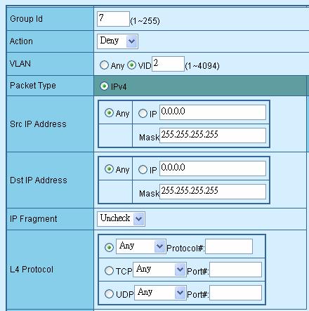
44 4.9 Access Control List The Access Control List (ACL) is a concept in computer security used to enforce privilege separation. It is a means of determining the appropriate access rights to a given object depending on certain aspects of the process that is making the request, principally the process's user identifier. Access Control List (ACL) is a mechanism that implements access control for a system resource by listing the identities of the system entities that are permitted or denied to access the resource. The screen in following screen appears; table 4-5 descriptions the Access Control List of Web Smart Switch. Figure 4-48 Access Control List (ACL) Web Page screen Object Description Group id Input a group ID and available range is Action VLAN Packet Type IP Fragment To assign Permit or Deny for Access Control List, the screen in Figure 4-49 appears. To choose VLAN type as Any or by VID (1-4094), the screen in Figure 4-50 appears. To choose Packet type as IPv4 or by Non-IPv4, the screen in Figure 4-51 appears. To decide to check or Uncheck the IP fragment, the screen in Figure 4-52 appears. L4 Protocol Provide additional L4 protocol for security on Layer 4 level, the screen in Figure 4-53 & 4-54 & 4-55 appears. Current List Display IPv4 or Non-IPv4 ACL groups, maximum up to 16 groups and the screen in Figure 4-56 appears. Add button Press this button for add Access Control List group on Web Smart Switch, the screen in Figure 4-57 & 4-58 appears. Del button Press this button for delete Access Control List group on Web Smart Switch, the screen in Figure 4-59 to 4-60 appears. Table 4-5 Descriptions of the Access Control List (ACL) screen Objects
 Web Page screen -")
45 Figure 4-49 Access Control List (ACL) Web Page screen Figure 4-50 Access Control List (ACL) Web Page screen
46 Figure 4-51 Access Control List (ACL) Web Page screen Figure 4-52 Access Control List (ACL) Web Page screen
47 Figure 4-53 Access Control List (ACL) Web Page screen Figure 4-54 Access Control List (ACL) Web Page screen
 Web Page screen -")
48 Figure 4-55 Access Control List (ACL) Web Page screen Figure 4-56 Access Control List (ACL) Web Page screen
49 Figure 4-57 Access Control List (ACL) Web Page screen Figure 4-58 Access Control List (ACL) Web Page screen
50 Figure 4-59 Access Control List (ACL) Web Page screen Figure 4-60 Access Control List (ACL) Web Page screen
51 Figure 4-61 Access Control List (ACL) Web Page screen Figure 4-62 Access Control List (ACL) Web Page screen For more detail information about Access Control List applications, please refer to Appendix B at page
52 4.10 Web Smart Function This function could provide you to define device indicate connect to each port on Web Smart Switch, the screen in Figure 4-63 appears. Figure 4-63 Web Smart Funciton Web Page screen The available options are shown as below: 1. PC 2. PC+Voip 3. Switch 4. Router 5. AP 6. Server 7. Printer 8. Guest 9. Other The screen in Figure 4-64 appears and the setup procedure shown as below: 1. Choose a device from options of Select a port function, the screen in Figure 4-65appears. 2. Check the port that need to marked, the screen in Figure 4-66 appears. 3. After setup completed, press Save to save current configuration, the screen in Figure 4-67 appears. 4. Please press Back for return to Web Smart Function screen, the screen in Figure 4-68 appears

53 Figure 4-64 Web Smart Funciton Web Page screen Figure 4-65 Web Smart Funciton Web Page screen
54 Figure 4-66 Web Smart Funciton Web Page screen This function also provides Apply for all ports option from Select a port function, the setup procedure shown as below: 1. Choose a device and check Apply for all ports from options of Select a port function, the screen in Figure 4-67appears. 2. Check any port then all port will be select; the screen in Figure 4-68 appears. 3. After setup completed, press Save to save current configuration, the screen in Figure 4-69 appears. 4. Please press Back for return to Web Smart Function screen, the screen in Figure 4-70 appears
55 Figure 4-67 Web Smart Function Web Page screen Figure 4-68 Web Smart Funciton Web Page screen
56 Figure 4-69 Web Smart Funciton Web Page screen Figure 4-70 Web Smart Funciton Web Page screen
57 4.11 Misc Operation This section provide Misc Operation of Web Smart Switch, the screen in Figure 4-71 appears and table 4-6 descriptions the Misc Operation objects of Web Smart Switch. Figure 4-71 Misc Operation Web Page screen Object Description Switch Configuration Provide Advanced Switch Configuration and available options are Broadcast Storm Filter. Collision Retry Forever. MAC Table Auto-Aging. MAC Table Hashing. Web Auto Logout Time. Please refer to section for detail description. TFTP Firmware Update Password Setting IP Configuration Factory Default Reboot System System Information Provide firmware upgrade on Web Smart Switch; please refer to section for detail description. Provide password setting on Web Smart Switch; please refer to section for detail description. Provide IP address configuration on Web Smart Switch; please refer to section for detail description. Provide Factory Default function on Web Smart Switch; please refer to section for detail description. Provide Reboot function on Web Smart Switch; please refer to section for detail description. Display System Information on Web Smart Switch; please refer to section for detail description. Table 4-6 Descriptions of the Misc Operation screen Objects
58 Switch Configuration Choose Switch Configuration from Misc Operation of Web Smart Switch( please see the Figure 4-72), the screen in Figure 4-73 appears and table 4-7 descriptions the Switch Configuration from Misc Operation of Web Smart Switch. Figure 4-72 Switch Configuration Web Page screen Object Broadcast Storm Filter Collision Retry Forever MAC Table Auto-Aging MAC Table Hashing Web Auto Logout Time Apply button Description Provide Broadcast storm filter function and available options are Off. 1/2. MAC 1/4. 1/8.1/16. Default mode is Off; the screen in Figure 4-72 appears. Provide Collision Retry Forever function Disable or Enable on Web Smart Switch; If this function is disabled, when a packet meet a collision, the Web Smart Switch will retry 6 times before discard the packets. Otherwise, the Web Smart Switch will retry until the packet is successfully sent. Default mode is Enable and the screen in Figure 4-73 appears. Provide MAC address table aging time setting on Web Smart Switch; available options are Disable. 150 sec. 300 sec. 600 sec. Default mode is 300 sec and the screen in Figure 4-74 appears. Provide MAC address table Hashing setting on Web Smart Switch; available options are CRC Hash and Direct Map. Default mode is CRC Hash and the screen in Figure 4-75 appears. Provide Web auto logout time setting on Web Smart Switch; available options are 5 min. 10 min. 20 min. Default mode is 5 min and the screen in Figure 4-76 appears. Press this button for save current Switch configuration on Web Smart Switch. Table 4-7 Descriptions of the Switch Configuration screen Objects
59 Figure 4-73 Switch Configuration Web Page screen Figure 4-74 Switch Configuration Web Page screen
60 Figure 4-75 Switch Configuration Web Page screen Figure 4-76 Switch Configuration Web Page screen
61 TFTP Firmware Upgrade This section provides Firmware upgrade through TFTP method on Web Smart Switch, the screen in Figure 4-77 appears. Figure 4-77 TFTP Firmware Update Web Page screen
62 Password Setting This section provides password setting of Web Smart Switch, the screen in Figure 4-78 appears and table 4-8 descriptions the Password Setting. Figure 4-78 Password Setting Web Page screen Object Description Password Protection Notice: Provide Password protection function Disable or Enable on Web Smart Switch; Default mode is Enable. User Name Provide to modify password on Web Smart Switch and maximum up to six characters. Default User Name is admin. New Password Provide to modify and input a new password on Web Smart Switch; maximum up to six characters. Default password is admin. Password Again Provide to input again new password for confirm on Web Smart Switch; maximum up to six characters. Default password is admin. Apply button Press this button for save current Password Setting on Web Smart Switch. Table 4-8 Descriptions of the Password Setting screen Objects Once disable the password protection then user name and password modify is not allow to use
63 IP Configuration This section provides IP Configuration on Web Smart Switch; the screen in Figure 4-79 appears and tables 4-9 descriptions the IP Configuration. Figure 4-79 IP Configuration Web Page screen MAC Address Display MAC address on Web Smart Switch. IP Address Provide to modify IP Address on Web Smart Switch. Default IP address is Subnet Mask Provide to modify Subnet Mask on Web Smart Switch. Default Subnet Mask is Default Gateway Provide to modify Default Gateway on Web Smart Switch. Default Gateway is Apply button Press this button for save current IP Configuration on Web Smart Switch. Once press the Apply button then the pop window with IP changed. Please Click OK to Re-login appears. Press OK to re-login Web Smart Switch with new IP address. Table 4-9 Descriptions of the IP Configuration screen Objects
64 Factory Default This section provides Factory Default function on Web Smart Switch, after choose this function and the following screen appears in Figure Please press OK button to take effect and the switch will reset to factory default mode and ask you to waiting rebooting around 10 sec, press OK button to re-login the Web Smart Switch. The screen in Figure 4-81& 4-82 & 4-83 appears. Figure 4-80 Factory Default Web Page screen Figure 4-81 Factory Default Web Page screen
65 Figure 4-82 Factory Default Web Page screen Figure 4-83 Factory Default Web Page screen
66 Reboot System This section provides Reboot function on Web Smart Switch, after choose this function and the following screen appears in Figure Please press OK button to take effect and the switch will reboot and ask you to waiting rebooting around 10 sec, press OK button to re-login the Web Smart Switch. The screen in Figure 4-85 & 4-86 & 4-87 appears. Figure 4-84 Reboot Web Page screen Figure 4-85 Reboot Web Page screen
67 Figure 4-86 Reboot Web Page screen Figure 4-87 Reboot Web Page screen
68 System Information This section display system information on Web Smart Switch, after choose this function and the following screen appears in Figure Figure 4-88 System Information Web Page screen
69 4.12 Logout This section provide web logout function on Web Smart Switch, after choose this function and the following screen appears in Figure Please press OK button to take effect and Logout pop window appears, press OK button to re-login the Web Smart Switch. The screen in Figure 4-90 & 4-91 & 4-92 appears. Figure 4-89 Logout Web Page screen
70 Figure 4-90 Logout Web Page screen Figure 4-91 Logout Web Page screen
71 Figure 4-92 Logout Web Page screen
72 5. SWITCH OPERATION 5.1 Address Table The Switch is implemented with an address table. This address table composed of many entries. Each entry is used to store the address information of some node in network, including MAC address, port no, etc. This information comes from the learning process of Ethernet Switch. 5.2 Learning When one packet comes in from any port. The Switch will record the source address, port no. And the other related information in address table. This information will be used to decide either forwarding or filtering for future packets. 5.3 Forwarding & Filtering When one packet comes from some port of the Ethernet Switching, it will also check the destination address besides the source address learning. The Ethernet Switching will lookup the address-table for the destination address. If not found, this packet will be forwarded to all the other ports except the port which this packet comes in. And these ports will transmit this packet to the network it connected. If found, and the destination address is located at different port from this packet comes in, the Ethernet Switching will forward this packet to the port where this destination address is located according to the information from address table. But, if the destination address is located at the same port with this packet comes in, then this packet will be filtered. Thereby increasing the network throughput and availability. 5.4 Store-and-Forward Store-and-Forward is one type of packet-forwarding techniques. A Store-and Forward Ethernet Switching stores the incoming frame in an internal buffer, do the complete error checking before transmission. Therefore, no error packets occurrence, it is the best choice when a network needs efficiency and stability. The Ethernet Switch scans the destination address from the packet-header, searches the routing table provided for the incoming port and forwards the packet, only if required. The fast forwarding makes the switch attractive for connecting servers directly to the network, thereby increasing throughput and availability. However, the switch is most commonly used to segment existing hubs, which nearly always improves overall performance. An Ethernet Switching can be easily configured in any Ethernet network environment to significantly boost bandwidth using conventional cabling and adapters. Due to the learning function of the Ethernet switching, the source address and corresponding port number of each incoming and outgoing packet are stored in a routing table. This information is subsequently used to filter packets whose destination address is on the same segment as the source address. This confines network traffic to its respective domain, reducing the overall load on the network. The Switch performs "Store and forward" therefore, no error packets occur. More reliably, it reduces the re-transmission rate. No packet loss will occur. 5.5 Auto-Negotiation The STP ports on the Switch have built-in "Auto-negotiation". This technology automatically sets the best possible bandwidth when a connection is established with another network device (usually at Power On or Reset). This is done by detect the modes and speeds at the second of both device is connected and capable of, both 10Base-T and 100Base-TX devices can connect with the port in either Half- or Full-Duplex mode. 1000Base-T can be only connected in Full-duplex mode
73 6.TROUBLESHOOTING This chapter contains information to help you solve problems. If the Switch is not functioning properly, make sure the Ethernet Switch was set up according to instructions in this manual. The Link LED is not lit Solution: Check the cable connection and remove duplex mode of the Switch. Some stations cannot talk to other stations located on the other port Solution: Please check the VLAN, port trunking function that may introduce this kind of problem. Performance is bad Solution: Check the full duplex status of the Ethernet Switch. If the Ethernet Switch is set to full duplex and the partner is set to half duplex, then the performance will be poor. 100Base-TX port link LED is lit, but the traffic is irregular Solution: Check that the attached device is not set to dedicate full duplex. Some devices use a physical or software switch to change duplex modes. Auto-negotiation may not recognize this type of full-duplex setting. Why the Switch doesn t connect to the network Solution: Check the LNK/ACT LED on the switch Try another port on the Switch Make sure the cable is installed properly Make sure the cable is the right type Turn off the power. After a while, turn on power again. How to deal forgotten password situation of FGSW-2402VS/FGSW-2620VSF Solution: Please press Reset button at front panel for 5 seconds then the Web Smart Switch will reset to factory default mode(username and password: admin)
74 APPENDIX A - NETWORKING CONNECTION A.1 Switch s RJ-45 Pin Assignments 1000Mbps, 1000Base-T Contact MDI MDI-X 1 BI_DA+ BI_DB+ 2 BI_DA- BI_DB- 3 BI_DB+ BI_DA+ 4 BI_DC+ BI_DD+ 5 BI_DC- BI_DD- 6 BI_DB- BI_DA- 7 BI_DD+ BI_DC+ 8 BI_DD- BI_DC- 10/100Mbps, 10/100Base-TX Contact RJ-45 Connector pin assignment MDI Media Dependant Interface MDI-X Media Dependant Interface -Cross 1 Tx + (transmit) Rx + (receive) 2 Tx - (transmit) Rx - (receive) 3 Rx + (receive) Tx + (transmit) 4, 5 Not used 6 Rx - (receive) Tx - (transmit) 7, 8 Not used A.2 RJ-45 cable pin assignment The standard RJ-45 receptacle/connector
75 There are 8 wires on a standard UTP/STP cable and each wire is color-coded. The following shows the pin allocation and color of straight cable and crossover cable connection: Figure A-1: Straight-Through and Crossover Cable Please make sure your connected cables are with same pin assignment and color as above picture before deploying the cables into your network
76 APPENDIX B - ACCESS CONTROL LIST APPLICATION GUIDE Introduction: What is Access Control List An Access Control List (ACL) consists of a set of rules which are matched sequentially against a packet. When a packet meets the match criteria of a rule, the specified rule action (Permit/Deny) is taken and the additional rules are not checked for a match. On this sample the switch to which an ACL applies must be specified, as well as whether it applies to inbound or outbound traffic. Rules for the ACL are specified/created using the ACL Rule Configuration menu. ACL Concepts Object Description Group id Input a group ID and available range is Action To assign Permit or Deny for Access Control List VLAN To choose VLAN type as Any or by VID (1-4094) Packet Type IP Fragment L4 Protocol Current List Add button Del button To choose Packet type as IPv4 or by Non-IPv4 To decide to check or Uncheck the IP fragment Provide additional L4 protocol for security on Layer 4 level Display IPv4 or Non-IPv4 ACL groups, maximum up to 16 groups Press this button for add Access Control List group on Web Smart Switch Press this button for delete Access Control List group on Web Smart Switch FGSW- ACL Configure screen

77 Before the ACL Configure Notice It is important to set the VLAN mode to Port-Based or 802.1Q VLAN before you start the ACL configure. Due to the ACL will check the VLAN ID if necessary, the VLAN mode must be set to Port-Based or 802.1Q mode. And once the VLAN mode is changed, the system has to reboot to apply the new settings. To set up the VLAN mode, click the VLAN Configuration at the Function Menu tree. The VLAN mode page appears as the following:

78 Deny Policy Sample Case 1: Deny specific Source IP Address Host Purpose: Verify positive and negative matches to a specific host IP address with a 32 bit mask, no matter the rule defined as permit or deny. Check for Class A,B, and C address. 1. To set a Host as the target at this case. 2. Once the deny policy be applied, all IP packets from the target Host IP Address will be dropped. 3. No matter IP packets form the target be transmitted to Internet or Intranet within the same IP segment, they will be dropped. Case Design: Action Match Source IP Address Destination IP Address DENY IP Host IP / ANY Device Connection and Configuration: Target Stream ID Source Address Destination Address Protocol Host Any Any ACL Policy Configuration:
79 ACL Policy Entry:
80 Case 2: Deny specific Source IP Address Class C Purpose: Verify a positive and negative matches to network IP address with a Class C (24 bit mask), no matter the rule defined as permit or deny. 1. Set Hosts within the same Class C Network domain, as the targets at this case. 2. Once the deny policy be applied, all IP packets from the targets IP Addresses will be dropped. 3. No matter IP packets form the targets be transmitted to Internet or Intranet within the same IP segment, they will be dropped. Case Design: Action Match Source IP Address Destination IP Address DENY IP Class C / ANY Device Connection and Configuration: Target Stream ID Source Address Destination Address Protocol Class C / Any Any ACL Policy Configuration:

81 ACL Policy Entry:

82 Case 3: Deny IP packets to specific Class C network Purpose: Verify a positive and negative matches to network IP address with a Class C (24 bit mask), no matter the rule defined as permit or deny. 1. Any packets pass through the switch will be dropped if the Destination IP Addresses match specific Class C. 2. Any packets pass through the switch will be forwarded if the Destination IP Addresses not match specific Class C. Case Design: Action Match Source IP Address Destination IP Address DENY IP Any Class C / Device Connection and Configuration: Stream Target ID Source Address Destination Address / Any 3 Any Protocol Any
83 ACL Policy Configuration: ACL Policy Entry:

84 Case 4: Deny specific VLAN packets Purpose: Verify a positive and negative matches to network IP address with a specific VLAN ID, no matter the rule defined as permit or deny. 1. Packets with VLAN ID= specific ACL VLAN ID will be dropped. 2. Packets with VLAN ID not match the specific ACL VLAN ID will be forwarded. Case Design: Action Match Source IP Address Destination IP Address DENY VLAN ANY ANY Device Connection and Configuration: ACL Policy Configuration:
85 - 85 -

86 Case 5: Deny Specify Protocol HTTP / WWW Purpose: Verify positive and negative matches to network IP address with a specific protocol or TCP/UDP Port number, no matter the rule defined as permit or deny. 1. Packets with Layer 4 protocol match the specific ACL protocol will be dropped. 2. Packets with Layer 4 protocol not match the specific ACL protocol will be forwarded. Case Design: Action DENY Match Protocol Service Type HTTP/WWW ( Port 80) Source IP Address Host Destination IP Address ANY Device Connection and Configuration: Stream Target ID Source Address Destination Address / Host ANY Protocol HTTP ( Port 80) ACL Policy Configuration:

87 ACL Policy Entry:
 Source IP Address Host Destination IP Address ANY Device Connection and Configuration: ACL Policy")
88 Case 6: Deny Specify Protocol SMTP Purpose: 1. SMTP packets from specific Host IP Address will be dropped. 2. Other packets from specific Host IP Address will be forwarded. Case Design: Action DENY Match Protocol Service Type SMTP ( Port 25) Source IP Address Host Destination IP Address ANY Device Connection and Configuration: ACL Policy Configuration:

89 ACL Policy Entry: 2080-A
24-Port 10/100Mbps + 2-Port. Gigabit Ethernet Switch FGSW User s Manual
 24-Port 10/100Mbps + 2-Port Gigabit Ethernet Switch FGSW-2620 User s Manual Trademarks Copyright PLANET Technology Corp. 2007. Contents subject to revision without prior notice. PLANET is a registered
10/100/1000Mbps. Gigabit Ethernet Switch GSW-2401/GSW User's Manual
 10/100/1000Mbps Gigabit Ethernet Switch GSW-2401/GSW-1601 User's Manual Trademarks Copyright PLANET Technology Corp. 2005. Content subjects to revision without prior notice. PLANET is a registered trademark
16/24-Port 10/100Mbps with 2 Gigabit TP / SFP Combo Web Smart Switch
 User's Manual FGSW-1820CS FGSW-2620CS 16/24-Port 10/100Mbps with 2 Gigabit TP / SFP Combo Web Smart Switch - 1 - Trademarks Disclaimer Copyright PLANET Technology Corp. 2008. Contents subject to revision
10/100/1000Mbps 16/24-port Web Smart Gigabit Ethernet Switch GSW-1600S/GSW-2400S. User s Manual
 10/100/1000Mbps 16/24-port Web Smart Gigabit Ethernet Switch GSW-1600S/GSW-2400S User s Manual Trademarks Copyright PLANET Technology Corp. 2004. Contents subject to which revision without prior notice.
5/8-Port 10/100/1000Mbps. Industrial Gigabit Ethernet Switch IGS-501 / IGS-801 / IGS-501T / IGS-801T. User's Manual
 5/8-Port 10/100/1000Mbps Industrial Gigabit Ethernet Switch IGS-501 / IGS-801 / IGS-501T / IGS-801T User's Manual Trademarks Copyright PLANET Technology Corp. 2009. Contents subject to revision without
8-Port 10/100Mbps with 4-Port PoE Web Smart Ethernet Switch FSD-804PS. User s Manual
 8-Port 10/100Mbps with 4-Port PoE Web Smart Ethernet Switch FSD-804PS User s Manual - 1 - Trademarks Disclaimer Copyright PLANET Technology Corp. 2006. Contents subject to revision without prior notice.
8-Port 10/100TX 802.3at PoE + 1-Port 10/100/1000T + 1-Port 100/1000X SFP Desktop Switch FGSD-1011HP. User s Manual
 8-Port 10/100TX 802.3at + 1-Port 10/100/1000T + 1-Port 100/1000X SFP Desktop Switch FGSD-1011HP User s Manual Copyright Copyright 2017 by PLANET Technology Corp. All rights reserved. No part of this publication
Fast / Gigabit Ethernet Switch Module. MII series. User's Manual
 Fast / Gigabit Ethernet Switch Module MII series User's Manual Trademarks Copyright PLANET Technology Corp. 2008. Contents subject to revision without prior notice. PLANET is a registered trademark of
5/8-Port Industrial Fast Ethernet Switch ISW-500/ISW-800. User's Manual
 5/8-Port Industrial Fast Ethernet Switch ISW-500/ISW-800 User's Manual Trademarks Copyright PLANET Technology Corp. 2006. Contents subject to which revision without prior notice. PLANET is a registered
8-Port 10/100TX 802.3at PoE + 2-Port 10/100TX Desktop Switch FSD-1008HP. User s Manual
 8-Port 10/100TX 802.3at + 2-Port 10/100TX Desktop Switch FSD-1008HP User s Manual Copyright Copyright 2017 by PLANET Technology Corp. All rights reserved. No part of this publication may be re-produced,
5-Port 10/100Mbps with 4-Port PoE. Industrial Fast Ethernet Switch ISW-504PT / ISW-514PT / ISW-514PT15 / ISW-514PTF. User's Manual
 5-Port 10/100Mbps with 4-Port PoE Industrial Fast Ethernet Switch ISW-504PT / ISW-514PT / ISW-514PT15 / ISW-514PTF User's Manual Trademarks Copyright PLANET Technology Corp. 2010 Contents subject revision
100Base-FX to 10/100Base-TX. PoE. Media Converter. FCU-1802Px. User s Manual
 100Base-FX to 10/100Base-TX PoE Media Converter FCU-1802Px User s Manual Trademarks Copyright Antaira Technologies 2013. Contents subject to revision without prior notice. Antaira is a registered trademark
Revision PLANET NOVASwitch User's Manual FOR MODELS: GSW-800S Part No.: EM-GSW8V1
 Trademarks Copyright PLANET Technology Corp. 2002. Contents subject to revision without prior notice. PLANET is a registered trademark of PLANET Technology Corp. All other trademarks belong to their respective
LevelOne GSW-2472TGX. 24Fast/2 Gigabit Ethernet combo Web Smart Switch. User`s Manual
 LevelOne GSW-2472TGX 24Fast/2 Gigabit Ethernet combo Web Smart Switch User`s Manual Contents 1. INTRODUCTION...1 Features...1 Software Features...2 Package Contents...3 2. HARDWARE DESCRIPTION...5 Front
User's Manual FT-902 FT-902S15 FT-902S35 FT-902S50 FT-905A FT-906A20 / FT-906B20. 10/100Base-TX to 100Base-FX. Managed Media Converter
 User's Manual FT-902 FT-902S15 FT-902S35 FT-902S50 FT-905A FT-906A20 / FT-906B20 10/100Base-TX to 100Base-FX Managed Media Converter Trademarks Copyright PLANET Technology Corp. 2010. Contents subject
24-Port 10/100/1000T 802.3at PoE + 2-Port 1000X SFP Gigabit Ethernet Switch with LCD PoE Monitor (300W)
") 24-Port 10/100/T 802.3at + 2-Port X SFP Gigabit Ethernet Switch with LCD Monitor (300W) Physical Port 24-port 10/100/BASE-T Gigabit Ethernet RJ45 copper 2 BASE-X mini-gbic SFP interfaces Power over Ethernet
24-Port 10/100/T 802.3at + 2-Port X SFP Gigabit Ethernet Switch with LCD Monitor (300W) Physical Port 24-port 10/100/BASE-T Gigabit Ethernet RJ45 copper 2 BASE-X mini-gbic SFP interfaces Power over Ethernet
LevelOne GES GE with 1 Combo SFP Web Smart Switch User Manual
 LevelOne GES-0852 8 GE with 1 Combo SFP Web Smart Switch User Manual Version 1.0-1109 1 FCC Certifications This Equipment has been tested and found to comply with the limits for a Class A digital device,
User s Manual of FGSD / FGSW Web Smart PoE Switch
 1 Trademarks Copyright PLANET Technology Corp. 2015. Contents are subject to revision without prior notice. PLANET is a registered trademark of PLANET Technology Corp. All other trademarks belong to their
4-Port 10/100Mbps +1/2 100FX Fiber Port. Industrial Fast Ethernet Switch. ISW-511 / ISW-621 Series. ISW-511T / ISW-621T Series.
 4-Port 10/Mbps +1/2 FX Fiber Port Industrial Fast Ethernet Switch ISW-511 / ISW-621 Series ISW-511T / ISW-621T Series User's Manual Trademarks Copyright PLANET Technology Corp. 2010 Contents subject revision
4-Port 10/100Mbps +1/2 100FX Fiber Port. Industrial Fast Ethernet Switch. ISW-511 / ISW-621 Series. ISW-511T / ISW-621T Series.
 4-Port 10/Mbps +1/2 FX Fiber Port Industrial Fast Ethernet Switch ISW-511 / ISW-621 Series ISW-511T / ISW-621T Series User's Manual Trademarks Copyright PLANET Technology Corp. 2015 Contents are subject
S7055xM / S7075xM Web Smart Managed 5-Port / 7-Port 10/100 Fast Ethernet Switch w/vlan Support Installation Guide
 S7055xM / S7075xM Web Smart Managed 5-Port / 7-Port 10/100 Fast Ethernet Switch w/vlan Support Installation Guide January 2005 VERSITRON, Inc. 83 Albe Drive / Suite C Newark, DE 19702 A050130380 The information
Copyright PLANET Technology Corp Contents subject to revision without prior notice.
 Copyright Copyright PLANET Technology Corp. 2004. Contents subject to revision without prior notice. PLANET is a registered trademark of PLANET Technology Corp. The information in this manual is subject
10/100/1000Mbps 16/24-Port Web Smart Gigabit Ethernet Switch
 User's Manual GSW-1602SF GSW-2404SF GSW-2416SF 10/100/1000Mbps 16/24-Port Web Smart Gigabit Ethernet Switch Trademarks Copyright PLANET Technology Corp. 2006. Contents subject to which revision without
48-Port 10/100Mbps + 4 Gigabit TP / 2 SFP Managed Switch
 High-Density / Cost-effective / Powerful class Fast Ethernet solution for SMB / Enterprise Network The PLANET is 48-Port 10/100Mbps + 4 Gigabit TP / 2 SFP Managed Switch with advanced Web-based management
Product names mentioned in this manual may be trademarks or registered trademarks of those products.
 FCC Statement The FCC (Federal Communications Commission) restricts the amount of radio frequency emission and radiation coming from computer equipment. The equipment introduced in this manual has been
PLANET Fiber Transceiver MFB-Series/MGB-Series/MTB-Series
 PLANET Fiber Transceiver MFB-Series/MGB-Series/MTB-Series User s Manual Trademarks Copyright PLANET Technology Corp. 2018 Contents are subject to revision without prior notice. PLANET is a registered trademark
User Guide. FSW-1641TX/2441TX 16/24 10/100Base-TX Web Smart Switch. FSW-1641TX 16 port 10/100Base-TX Web Smart Switch
 FSW-1641TX/2441TX 16/24 10/100Base-TX Web Smart Switch User Guide FSW-1641TX 16 port 10/100Base-TX Web Smart Switch FSW-2441TX 24 port 10/100Base-TX Web Smart Switch Contents 1. PRODUCT INTRODUCTION...1
FCC COMPLIANCE STATEMENT
 FCC COMPLIANCE STATEMENT This equipment has been tested and found to comply with the limits of a Class A computing devices, pursuant to Part 15 of the FCC rules. These limits are designed to provide reasonable
24-Port 100Base-FX SFP + 2- Gigabit Managed Ethernet Switch
 24-Port Base-FX SFP + 2- Gigabit Managed Ethernet Switch Multi Port / Flexible Base-FX Fiber Optical connective for Distance Extension Solution The FTTx network applications are part of our life particularly
Installation Guide 24-port 10/100 Fast Ethernet Switch with 1 Fiber Connection Model Name: KS-324F
 Installation Guide 24-port 10/100 Fast Ethernet Switch with 1 Fiber Connection Model Name: KS-324F We make no warranties with respect to this documentation and disclaim any implied warranties of merchantability,
8-Port 10/100/1000T Gigabit Ethernet Switch with. 4-Port 802.3at PoE+ Injector GSD-804P. User s Manual
 8-Port 10/100/1000T Gigabit Ethernet Switch with 4-Port 802.3at + Injector GSD-804P User s Manual Trademarks Copyright PLANET Technology Corp. 2016. Contents are subject to revision without prior notice.
Best Connectivity. 5-Port 10/100Mbps Desktop Switch with 4-Port PoE
 NS0098 is a 5 10/100Mbps ports unmanaged switch that requires no configuration and provides 4 PoE (Power over Ethernet) ports. It can automatically detect and supply power with all IEEE 802.3af compliant
Industrial 8-Port 10/100TX 802.3at PoE+ + 2-Port Gigabit TP/SFP Combo Ethernet Switch IFGS-1022HPT. User s Manual
 Industrial 8-Port 10/100TX 802.3at PoE+ + 2-Port Gigabit TP/SFP Combo Ethernet Switch IFGS-1022HPT User s Manual Table of Contents 1. Package Contents... 3 2. Hardware Introduction... 4 2.1 Physical Dimensions...
Product features. Applications
 Applications Layer 2+ VLAN static routing application The managed switch features a built-in, robust IPv4/IPv6 Layer 3 traffic static routing protocol to ensure reliable routing between VLANs and network
FAST ETHERNET RACKMOUNT WEB-SMART SWITCH USER MANUAL
 FAST ETHERNET RACKMOUNT WEB-SMART SWITCH USER MANUAL MODEL 505093 WITH OPTIONAL GIGABIT PORTS INT-505093-UM-0906-01 TABLE OF CONTENTS section page 1. Introduction & Features...3 2. Hardware Installation...3
Switch manual Models &
 Fast Ethernet Web-Smart Switch user manual Models 523813 & 523820 INT-523813/523820-UM-0607-01 introduction Thank you for purchasing the INTELLINET NETWORK SOLUTIONS Fast Ethernet Web-Smart Switch (6 RJ-45
48-Port Gigabit with 4 Shared SFP Managed Switch
 48-Port Gigabit with 4 Shared SFP Managed Switch High-Density / Cost-effective / Telecom class Gigabit solution for Enterprise backbone and Data Center Networking The PLANET is a Layer 2 / Layer 4 full
Installation Guide. Web Smart Managed 10/100 Fast Ethernet Switches with VLAN Support
 Installation Guide Web Smart Managed 10/100 Fast Ethernet Switches with VLAN Support KS-115FM-V KS-117FM-V DOC.060510-1- (C) 2006 KTI Networks Inc. All rights reserved. No part of this documentation may
24-Port 10/100TX + 4-Port Gigabit Managed Switch with 2 Combo 100/1000X SFP Ports
 24-Port 10/100TX + 4-Port Gigabit Managed Switch with 2 Combo 100/X SFP Ports Full-Functioned Layer 2 / Layer 4 Managed Switch for Enterprise and Campus Networking PLANET is a 24-port 10/100Mbps Fast Ethernet
User s Manual IGT-902 / 902T IGT-902S / 902TS IGT-905A. 10/100/1000Base-T to 1000Base-SX / LX. Industrial Managed Media Converter
 User s Manual IGT-902 / 902T IGT-902S / 902TS IGT-905A 10/100/1000Base-T to 1000Base-SX / LX Industrial Managed Media Converter -1- Trademarks Copyright PLANET Technology Corp. 2010. Contents subject to
16 Port Nway switch. User s manual
 16 Port Nway switch User s manual FCC Class A Appliance This equipment generates and uses radio frequency energy.if it is not installed and used properly in strict accordance with the manufactures, it
User s Manual of FGSW-1816HPS
 1 Trademarks Copyright PLANET Technology Corp. 2014. Contents are subject to revision without prior notice. PLANET is a registered trademark of PLANET Technology Corp. All other trademarks belong to their
IN-16POEWM. User Manual. 16 Port Fast Ethernet PoE Web Smart Switch. Version V100817
 IN-16POEWM User Manual 16 Port Fast Ethernet PoE Web Smart Switch Version V100817 FCC Warning This Equipment has been tested and found to comply with the limits for a Class-A digital device, pursuant to
WGSW Data Sheet
 28-Port 10/100/Mbps with 4 Shared SFP Managed Switch PLANET introduces the latest Managed Gigabit Switch - that is perfectly designed for SMB and SOHO network construction. Besides the hot IPv6 / IPv4
16-Port Web Smart Gigabit Ethernet Switch with 2 Shared SFP Interfaces GSW-1602SF Data Sheet
 16-Port Web Smart Gigabit Ethernet Switch with 2 Shared SFP Interfaces Robust Layer 2 Features High-Performaning Gigabit Solution for Enterprise Backbone and Data Center Networking PLANET's is a Layer
LevelOne GSW User Manual. 48-Port TP Fast Ethernet and 4-Port TP Gigabit w/ 2-Port shared SFP Web Smart Switch
 LevelOne GSW-5270 48-Port TP Fast Ethernet and 4-Port TP Gigabit w/ 2-Port shared SFP Web Smart Switch User Manual ii Safety FCC Warning This equipment has been tested and found to comply with the regulations
MS400870M. User's Guide. Ver.: Port GBE SFP Switch 19 1U 24x10/100/1000T Combo 10/1000X SFP
 MS400870M 24 Port GBE SFP Switch 19 1U 24x10/100/1000T Combo 10/1000X SFP User's Guide. Ver.:0.91 1 CE Mark Warning This is a Class A product. In a domestic environment, this product may cause radio interference
FSW-1609TFX FSW-2409TFX
 LevelOne FSW-1609TFX FSW-2409TFX 16/24-Port Fast Ethernet Switch w/ fiber module slot User Manual Version 1.1-0609 FCC Warning This equipment has been tested and found to comply with the regulations for
PLANET Fiber Transceiver MFB-Series/MGB-Series/MTB-Series
 PLANET Fiber Transceiver MFB-Series/MGB-Series/MTB-Series User s Manual Trademarks Copyright PLANET Technology Corp. 2017 Contents are subject to revision without prior notice. PLANET is a registered trademark
10/100BASE-TX TO 100BASE-FX MEDIA CONVERTERS EM4000 EM4001. Installation Guide
 10/100BASE-TX TO 100BASE-FX MEDIA CONVERTERS EM4000 EM4001 Installation Guide DOC.050523-EM400X -1- The information contained in this document is subject to change without prior notice. Copyright (C) All
FSW-1610TX FSW-2410TX
 LevelOne FSW-1610TX FSW-2410TX 16/24-Port Fast Ethernet Switch User Manual Version 1.1-0609 FCC Warning This equipment has been tested and found to comply with the regulations for a Class A digital device,
Ether-FSH2400C 24-port 10/100Base-TX Switch
 Ether-FSH2400C 24-port 10/100Base-TX Switch User s Manual FCC STATEMENT This equipment has been tested and found to comply with the limits for a class A device, pursuant to part 15 of the FCC rules. These
DynaGST/2402G USER S MANUAL
 DynaGST/2402G 24 Port 10/100/1000Base-T Gigabit Ethernet Switch with two SFP (mini) GBIC Slots PN: GEP-33224T-1 USER S MANUAL Content 1. Introduction... 1 Features... 2 Package Contents... 3 2. Hardware
8-Port 10/100Mbps + 2G TP / SFP Combo Managed Switch
 8-Port 10/100Mbps + 2G TP / SFP Combo Managed Switch Full-Functioned / Robust Layer2 Features Layer 2 / Layer 4 Managed Switch for Enterprise and Campus Networking The PLANET is an 8-Port 10/100Mbps Fast
UTM Content Security Gigabit Gateway CS-950
 UTM Content Security Gigabit Gateway CS-950 Quick Installation Guide Table of Contents 1. Package Contents... 3 2. Hardware Introduction... 4 2.1 Hardware Interface... 4 2.2 Hardware Installation... 6
LevelOne User Manual
 LevelOne User Manual FSW-1671 16-Port 10/100 Rackmount Smart Switch w/8 PoE Ports Ver1.0-0905 FCC Warning This Equipment has been tested and found to comply with the limits for a Class-A digital device,
KGS-510F Web Smart 6-Port Gigabit Ethernet Switch with Fiber Connectivity Installation Guide
 KGS-510F Web Smart 6-Port Gigabit Ethernet Switch with Fiber Connectivity Installation Guide DOC.060118-1- (C) 2005 KTI Networks Inc. All rights reserved. No part of this documentation may be reproduced
HES-3106-PLUS SERIES
 HES-3106-PLUS SERIES 5 PORTS 10/100/1000BASE-T ETHERNET MANAGED SWITCH WITH 1 PORT 1000BASE-X or 100/1000BASE-X UPLINK User s Guide Version 0.92 Trademarks CTS is a registered trademark of Connection Technology
100/1000BASE-X to 10/100/1000BASE-T at PoE Media Converter. GTP-805A User s Manual
 100/1000BASE-X to 10/100/1000BASE-T 802.3at PoE Media Converter GTP-805A User s Manual Trademarks Copyright PLANET Technology Corp. 2018. Contents are subject to revision without prior notice. PLANET is
Ethernet over VDSL2 Converter
 Ethernet over Converter VC-231 / VC-234 User s Manual Trademarks Copyright PLANET Technology Corp. 2009 Contents subject to revision without prior notice. PLANET is a registered trademark of PLANET Technology
SD24GS. 24-Port Web Smart Gigabit Ethernet Switch. User s Manual
 SD24GS 24-Port Web Smart Gigabit Ethernet Switch User s Manual FCC Warning This equipment has been tested and found to comply with the limits for a Class A digital device, pursuant to Part 15 of the FCC
10/100/1000T to Mini-GBIC Industrial Switch Converter 10/100/1000T to 1000SX/LX Industrial Switch Converter. AMG9011G-H (-40 to 75C) User Manual
 User Manual") 10/100/1000T to Mini-GBIC Industrial Switch Converter 10/100/1000T to 1000SX/LX Industrial Switch Converter AMG9011G-H (-40 to 75C) User Manual www.amgsystems.com Content Overview...1 Introduction... 1
10/100/1000T to Mini-GBIC Industrial Switch Converter 10/100/1000T to 1000SX/LX Industrial Switch Converter AMG9011G-H (-40 to 75C) User Manual www.amgsystems.com Content Overview...1 Introduction... 1
User s Manual FGSD-1022 FGSD-1022P FGSD-1022HP. 8-Port 10/100Mbps + 2 Gigabit TP/SFP Layer 2 Managed Switch
 User s Manual of FGSD-1022 User s Manual FGSD-1022 8-Port 10/100Mbps + 2 Gigabit TP/SFP Layer 2 Managed Switch FGSD-1022P 8-Port 10/100Mbps + 2 Gigabit TP/SFP Managed PoE Switch FGSD-1022HP 8-Port 10/100Mbps
310 SERIES LAYER 2 MANAGED NETWORK SWITCHES Quick Start Guide
 310 SERIES LAYER 2 MANAGED NETWORK SWITCHES AN-310-SW-F/R-8 AN-310-SW-F/R-16 AN-310-SW-F/R-24 AN-310-SW-F/R-8-POE AN-310-SW-F/R-16-POE AN-310-SW-F/R-24-POE FCC Warning Changes or modifications not expressly
Powerline Communication
 Networking & Communication Powerline Communication Powerline to Ethernet Converter PL-101E USB to Powerline Network Adapter - PL-101U USER S MANUAL 1 Copyright Copyright (C) 2002 PLANET Technology Corp.
GEU Port Gigabit Switch
 GEU-0522 5-Port Gigabit Switch Table Of Contents 1. INTRODUCTION... 3 1.1 Product Briefs... 3 1.2 Product Features... 3 1.3 Hardware Introduction... 4 2. CONNECTING THE SWITCH... 5 2.1 Package Contents...
24-Port Gigabit Ethernet Switches
 24-Port Gigabit Ethernet Switches User s Manual DOC.140930 FCC Certifications This Equipment has been tested and found to comply with the limits for a Class A digital device, pursuant to part 15 of the
GV-POE2401-V2 24-Port 802.3at Web Management PoE
 GV-POE2401-V2 24-Port 802.3at Web Management PoE Switch Packing List 1. GV-POE2401-V2 x 1 2. AC Power Cord x 1 3. Screw x 8 4. Rack Mount Kit x 1 5. Download Guide x 1 6. GV-POE2401-V2 Installation Guide
HES-3109 SERIES 9 PORTS 10/100/1000BASE-T MANAGEMENT ETHERNET SWITCH
 HES-3109 SERIES 9 PORTS 10/100/1000BASE-T MANAGEMENT ETHERNET SWITCH 8 PORTS 10/100/1000BASE-T MANAGEMENT ETHERNET SWITCH WITH 1 PORT 1000BASE-X UPLINK OR 1 PORT 100/1000BASE-X UPLINK 8 PORTS 10/100/1000BASE-T
Gigabit Network Switches
 Network Transmission Gigabit Network Switches Layer 2 (Non-PoE) Layer 3 (PoE-at) OVERVIEW This Enterprise-Class Network Switch provides 24 Gigabit Ethernet ports with 4 shared 100/1000Mbps SFP slots. This
SWH-3112 Series 12-port L2+ Managed Gigabit Fiber Switch User s Guide
 SWH-3112 Series 12-port L2+ Managed Gigabit Fiber Switch User s Guide Version: 1.0 Revision History Version Date Changes 0.9 11/10/2017 First release 1.0 05/08/2018 Use the new template FCC Warning This
BLACKBOX NETWORK SERVICES. one source for worldwide infrastructure services
 BLACKBOX NETWORK SERVICES one source for worldwide infrastructure services 24 Port 10/100Mbps plus 2 Gigabit TX/FX Auto-MDIX Modular Gigabit Ethernet Switch User s Manual FCC Warning This device has been
User Guide TL-SG1005D TL-SG1008D. 5/8-Port Gigabit Desktop Switch. alarm shop. Rev:
 User Guide TL-SG1005D TL-SG1008D 5/8-Port Gigabit Desktop Switch Rev:2.0.2 7106503707 COPYRIGHT & TRADEMARKS Specifications are subject to change without notice. is a registered trademark of TP-LINK TECHNOLOGIES
24-Port 10/100TX + 4-Port Gigabit Managed Switch with 2 Combo 100/1000X SFP Ports FGSW-2840 Data Sheet Layer 2 Features
 24-Port 10/100TX + 4-Port Gigabit Managed Switch with 2 Combo 100/X SFP Ports 1 Layer 2 / Layer 4 Managed Switch for Enterprise and Campus Networking PLANET's is a 24-port 10/100Mbps Fast Ethernet Switch
210 SERIES WEBSMART NETWORK SWITCHES Quick Start Guide AN-210-SW-F/R-8-POE AN-210-SW-F/R-16-POE AN-210-SW-F/R-24-POE AN-210-SW-F-48-POE
 210 SERIES WEBSMART NETWORK SWITCHES AN-210-SW-F/R-8-POE AN-210-SW-F/R-16-POE AN-210-SW-F/R-24-POE AN-210-SW-F-48-POE Araknis Networks 210 Series Websmart Network Switches FCC Warning Changes or modifications
10G/5G/2.5G/1G/100M Copper to 10GBASE-X SFP+ Media Converter. XT-705A User s Manual
 10G/5G/2.5G/1G/100M Copper to 10GBASE-X SFP+ Media Converter XT-705A User s Manual Trademarks Copyright PLANET Technology Corp. 2018. Contents are subject to revision without prior notice. PLANET is a
DynaGST/2402G. 24 Port 10/100/1000Base-T Gigabit Ethernet Switch with two SFP (mini) GBIC Slots PN: GEP-33224T USER S MANUAL
 GBIC Slots PN: GEP-33224T USER S MANUAL") DynaGST/2402G 24 Port 10/100/1000Base-T Gigabit Ethernet Switch with two SFP (mini) GBIC Slots PN: GEP-33224T USER S MANUAL Content 1. Introduction... 1 Features... 2 Package Contents... 3 2. Hardware
DynaGST/2402G 24 Port 10/100/1000Base-T Gigabit Ethernet Switch with two SFP (mini) GBIC Slots PN: GEP-33224T USER S MANUAL Content 1. Introduction... 1 Features... 2 Package Contents... 3 2. Hardware
ProSAFE 8-Port 10-Gigabit Web Managed Switch Model XS708Ev2 User Manual
 ProSAFE 8-Port 10-Gigabit Web Managed Switch Model XS708Ev2 User Manual April 2016 202-11656-01 350 East Plumeria Drive San Jose, CA 95134 USA Support Thank you for purchasing this NETGEAR product. You
ProSAFE 8-Port and 16-Port 10-Gigabit Ethernet Web Managed Switch Models XS708Ev2 and XS716E User Manual
 ProSAFE 8-Port and 16-Port 10-Gigabit Ethernet Web Managed Switch Models XS708Ev2 and XS716E User Manual March 2017 202-11656-03 350 East Plumeria Drive San Jose, CA 95134 USA Support Thank you for purchasing
24 Gigabit Fiber Copper PoE and Stacking Switch Series. Network Transmission Products 24 Gigabit Fiber Copper PoE and Stacking Switch Series.
 Network Transmission Products 24 Gigabit Fiber Copper PoE and Stacking Switch Series Overview The GE Security GE-DSG / GE-DSSG series is a Layer 2+ managed gigabit switch designed to handle extremely large
Trademarks. Statement of Conditions by NETGEAR, Inc. All rights reserved.
 2004 by NETGEAR, Inc. All rights reserved. Trademarks @2004 NETGEAR, Inc. NETGEAR, the Netgear logo, The Gear Guy and Everybody s connecting are trademarks of Netgear, Inc. in the United States and/or
FCN-3112 Series. 10/100/1000TX to 1000SX SNMP Managed Media Converter. Version 1.0 User Manual
 FCN-3112 Series 10/100/1000TX to 1000SX SNMP Managed Media Converter Version 1.0 User Manual Copyright 2018 Antaira Technologies, LLC. All Rights Reserved This document contains information, which is protected
User Guide TL-SG1024D 24-Port Gigabit Desktop/Rackmount Switch
 User Guide TL-SG1024D 24-Port Gigabit Desktop/Rackmount Switch Rev: 1.0.0 7106503213 COPYRIGHT & TRADEMARKS Specifications are subject to change without notice. is a registered trademark of TP-LINK TECHNOLOGIES
Long Reach. PoE over Coaxial / UTP. Extender Kit. LRP-101C-KIT and LRP-101U-KIT. User s Manual
 Long Reach PoE over Coaxial / UTP Extender Kit LRP-101C-KIT and LRP-101U-KIT User s Manual Trademarks Copyright PLANET Technology Corp. 2015. Contents are subject to revision without prior notice. PLANET
AMG9082W-HP260-C User s Manual
 8 x 10/100 PoE+ 802.3at w/ 2 Gigabit Combo Ports RJ45/SFP Fast Ethernet Switch AMG9082W-HP260-C User s Manual www.amgsystems.com FCC Warning This Equipment has been tested and found to comply with the
Hardened Web-Smart High Power PoE Ethernet Switch
 Quick Start Guide This quick start guide describes how to install and use the Hardened Web-Smart High Power PoE (Power over Ethernet) Ethernet Switch. This is the switch of choice for harsh environments
8-port 10/100TX + 2-Port 10/100/1000T/100/1000 SFP Combo with 8 PoE Injectors Industrial Ethernet Switch User Manual
 8-port 10/100TX + 2-Port 10/100/1000T/100/1000 SFP Combo with 8 PoE Injectors Industrial Ethernet Switch User Manual FCC Warning This Equipment has been tested and found to comply with the limits for a
IFS MC350-1T-2S User Manual
 IFS MC350-1T-2S User Manual P/N 1072683 REV A ISS 22OCT13 Copyright Trademarks and patents Manufacturer 2013 United Technologies Corporation Interlogix is part of UTC Climate Controls & Security, a unit
24 GE with 4 Shared SFP Web Smart Switch
 GES-2451 Version: 1 24 GE with 4 Shared SFP Web Smart Switch LevelOne GES-2451 is a powerful, high-performance Gigabit Ethernet switch with 24 10/100/1000Mbps ports shared 4 SFP(mini GBIC) ports, providing
Quick Start Guide. Gigabit Smart Switch Eco Fanless. Supports http and SNMP interfaces for switch management. LGB2118A LGB2124A
 LGB2118A LGB2124A Gigabit Smart Switch Eco Fanless Quick Start Guide Supports http and SNMP interfaces for switch management. Customer Support Information Order toll-free in the U.S.: Call 877-877-BBOX
MARQUE: TP-LINK REFERENCE: TPL_TLSF1016D CODIC:
 MARQUE: TP-LINK REFERENCE: TPL_TLSF1016D CODIC: 4076656 TL-SF1005D TL-SF1008D TL-SF1016D 10/100Mbps Desktop Switch REV: 1.0.0 1910010004 COPYRIGHT & TRADEMARKS Specifications are subject to change without
LevelOne FSW PoE Fast Ethernet Switch User Manual
 LevelOne FSW-0809 4+4 PoE Fast Ethernet Switch User Manual v1.0-0706 Safety FCC Warning This equipment has been tested and found to comply with the regulations for a Class B digital device, pursuant to
IFS MC-4TX Series Industrial Ethernet Switch User Manual
 IFS MC-4TX Series Industrial Ethernet Switch User Manual P/N 1069180 REV B ISS 01APR1 Copyright Disclaimer Trademarks and patents Intended use Manufacturer Certification FCC compliance ACMA compliance
Industrial 10/100/1000BASE-T to 100/1000BASE-X SFP Media Converter
 Industrial 10/100/BASE-T to 100/BASE-X SFP Media Converter Physical Port 1-port 10/100/BASE-T RJ45 with auto MDI / MDI-X function 1 SFP interface, 100/BASE-X dual mode (auto detection) Layer 2 Features
MIL-S24002TGxx. 24-port 10/100/1000 TX 2 Combo SFP Slots Unmanaged Switch. User Guide
 MIL-S24002TGxx 24-port 10/100/1000 TX 2 Combo SFP Slots Unmanaged Switch User Guide Rev.B 08-DEC2005 Regulatory Approval - FCC Class A - UL 1950 - CSA C22.2 No. 950 - EN60950 - CE - EN55022 Class A - EN55024
Industrial 5-Port Fast Ethernet Switches with SFP Slot and optional 4 PoE PSE Ports. Basic Model: KSD-541 PoE Model: KSD-541-P. Installation Guide
 Industrial 5-Port Fast Ethernet Switches with SFP Slot and optional 4 PoE PSE Ports Basic Model: KSD-541 PoE Model: KSD-541-P Installation Guide DOC.080104-1- (C) 2008 KTI Networks Inc. All rights reserved.
User s Manual of UPOE-800G/UPOE-1600G/UPOE-2400G
 1 Trademarks Copyright PLANET Technology Corp. 2017. Contents are subject to revision without prior notice. PLANET is a registered trademark of PLANET Technology Corp. All other trademarks belong to their
8-Port Gigabit Ethernet Smart Managed Plus Switch with 2-Port 10G/Multi-Gig Uplinks User Manual
 8-Port Gigabit Ethernet Smart Managed Plus Switch with 2-Port 10G/Multi-Gig Uplinks User Manual Model GS110EMX December 2017 202-11810-03 350 E. Plumeria Drive San Jose, CA 95134 USA Support Thank you
PowerLine HD. user manual. Model * INT UM
 PowerLine HD Ethernet Adapter user manual Model 503839* * This manual can also be used for the PowerLine HD Ethernet Adapter Starter Kit, Model 503808 INT-503839-UM-0608-01 introduction Thank you for purchasing
TE100-S16 16-Port 10/100Mbps Fast Ethernet Switch. User s Guide
 TE100-S16 16-Port 10/100Mbps Fast Ethernet Switch User s Guide FCC Warning This equipment has been tested and found to comply with the regulations for a Class A digital device, pursuant to Part 15 of the