Ch. 9 VTP (Trunking, VTP, Inter-VLAN Routing) CCNA 3 version 3.0
|
|
|
- Gwendolyn Richardson
- 5 years ago
- Views:
Transcription
1 Ch. 9 VTP (Trunking, VTP, Inter-VLAN Routing) CCNA 3 version 3.0
2 Overview Explain the origins and functions of VLAN trunking Describe how trunking enables the implementation of VLANs in a large network Define IEEE 802.1Q Define Cisco ISL Configure and verify a VLAN trunk Define VTP Explain why VTP was developed Describe the contents of VTP messages List and define the three VTP modes Configure and verify VTP on an IOS-based switch Explain why routing is necessary for inter-vlan communication Explain the difference between physical and logical interfaces Define subinterfaces Configure inter-vlan routing using subinterfaces on a router port 2


3 History of trunking a trunk is a single communications line that carries multiple channels of radio signals. A trunk is a physical and logical connection between two switches across which network traffic travels. 3
4 . A Closer look at VLAN Tagging ISL Ethernet Frame 1500 bytes plus 18 byte header (1518 bytes) IEEE 802.1Q SA and DA SA and 802.1q DA MACs MACsTag Type/Length Field Data (max 1500 bytes) CRC New CRC There are two types of VLAN Tagging: ISL (Inter-Switch Link) Cisco Proprietary IEEE 802.1Q 802.1Q is recommended by Cisco and is used with multi-vendor switches. Caution: Some older Cisco switches will only do ISL while some new Cisco switches will only do 802.1Q. The following slides on ISL and 802.1Q are FYI only. 4
5 IEEE 802.1Q NIC cards and networking devices can understand this baby giant frame (1522 bytes). However, a Cisco switch must remove this encapsulation before sending the frame out on an access link. SA and DA SA and 802.1q DA MACs MACsTag Type/Length Field Data (max 1500 bytes) CRC New CRC 2-byte TPID 2-byte TCI Tag Protocol Identifier Tag Control Info (includes VLAN ID) Significantly less overhead than the ISL As opposed to the 30 bytes added by ISL, 802.1Q inserts only an additional 4 bytes into the Ethernet frame 5

6 . Trunking operation or 802.1Q Trunking protocols were developed to effectively manage the transfer of frames from different VLANs on a single physical line. The trunking protocols establish agreement for the distribution of frames to the associated ports at both ends of the trunk. Trunk links may carry traffic for all VLANs or only specific VLANs. 6

7 . VLANs and trunking Non-Trunk Links Trunk Link Non-Trunk Links A trunk is a single channel between two points that are usually switching centers. It is important to understand that a trunk link does not belong to a specific VLAN. The responsibility of a trunk link is to act as a conduit for VLANs between switches and routers (or switches and switches). 7
8 . Configuring Trunking Note: On many switches, the switchport trunk encapsulation command must be done BEFORE the switchport mode trunk command. These commands will be explained in the following slides. 8
9 . Configuring Trunking Switch(config-if)switchport trunk encapsulation [dot1q isl] This command configures VLAN tagging on an interface if the switch supports multiple trunking protocols. The two options are: dot1q IEEE 802.1Q isl ISL The tagging must be the same on both ends. 9
10 Before attempting to configure a VLAN trunk on a port, determine what encapsulation the port can support. This can be done using the show port capabilities command. 10
11 . Configuring Trunking Switch(config-if)switchport mode [access trunk] By default, 2900XL switchports are configured as access ports. Not true on most other switches (default is dynamic desirable). An access port means that the port (interface) can only belong to a single VLAN. Access ports are used when: Only a single device is connected to the port Multiple devices (hub) are connected to the port, all belonging to the same VLAN Another switch is connected to this interface, but this link is only carrying a single VLAN (non-trunk link). Trunk ports are used when: Another switch is connected to this interface, and this link is carrying multiple VLANa (trunk link). 11
12 Configuring Trunking No VLAN Tagging Switch(config-if)switchport mode access VLAN Tagging Switch(config-if)switchport mode trunk 12
13 . DTP Dynamic Trunking Protocol To Trunk or not to Trunk (access mode), that is the question.

14 . DTP Dynamic Trunking Protocol The next few slides will give a brief overview of DTP. These slides refer to the Catalyst 2950 and 3550 switches. There may be some small differences with the 2900XL switches. 14
15 . DTP Dynamic Trunking Protocol Ethernet trunk interfaces support several different trunking modes. Access Dynamic desirable (default mode on Catalyst 2950 and 3550) Dynamic auto Trunk Non-negotiate dotq-tunnel (Not an option on the Catalyst 2950.) Using these different trunking modes, an interface can be set to trunking or nontrunking or even able to negotiate trunking with the neighboring interface. To automatically negotiate trunking, the interfaces must be in the same VTP domain. (VTP is discussed in the next section.) Trunk negotiation is managed by the Dynamic Trunking Protocol (DTP), which is a Cisco proprietary Point-to-Point Protocol. These various modes are configured using the switchport mode interface command 15
16 . DTP Dynamic Trunking Protocol These various modes are configured using the switchport mode interface command. We have already discussed the two non-dynamic options: Switch(config-if)switchport mode access Switch(config-if)switchport mode trunk These options set the interface to non-trunking (access) or trunking (trunk) 16
17 . DTP Dynamic Trunking Protocol All of these DTP modes and their various combinations can be somewhat confusing. Looking at some of the basic combinations can help clarify this. 17
18 . DTP Default for 2900XL Default for 2950 and 3550 By default, Ethernet interfaces on Catalyst 2950 and 3550 switches default to desirable mode. (2900XL switches default to access mode.) Desirable mode will create a trunk link if the neighboring interface is set to desirable, trunk, or auto mode. On 2950 and 3550 switches, because both interfaces by default are in desirable mode, this means a link between two of these switches will automatically become a trunk link unless configured otherwise. 18
19 . Creating VLANs Default: dynamic desirable This link will become a trunking link unless one of the ports is configured with as an access link, I.e. switchport mode access By default, all ports are configured as switchport mode dynamic desirable, which means that if the port is connected to another switch with an port configured with the same default mode (or desirable or auto), this link will become a trunking link. (See my article on DTP on my web site for more information.) When the switchport access vlan command is used, the switchport mode access command is not necessary since the switchport access vlan command configures the interface as an access port (non-trunk port). This will be discussed in more in the next chapter, section on DTP. 19
20 . DTP Default 2950/3550 This figure shows the various DTP trunking modes and the results of the different combinations. Selecting the right combination on the two ends of the link is important, as some combinations should not be used as they will have unexpected results. One combination that could result in traffic being blocked from transmitting the link is if one interface is in access mode and the neighboring interface is in trunk mode. 20
21 . VTP VLAN Trunking Protocol Create once and send to the other switches. VTP is a messaging protocol that uses Layer 2 trunk frames to manage the addition, deletion, and renaming of VLAN on a single domain. VTP messages are encapsulated in either Cisco proprietary ISL or IEEE 802.1Q protocol frames and then passed across trunk links to other devices. NOTE: before creating VLANs on the switch, you must first set up a VTP management domain

22 . Benefits of VTP (VLAN Trunking Protocol) Before discussing VTP, it is important to understand that VTP is not necessary in order to configure VLANs or Trunking on Cisco Switches. VTP is a Cisco proprietary protocol that allows VLAN configuration to be consistently maintained across a common administrative domain. VTP minimizes the possible configuration inconsistencies that arise when changes are made. Additionally, VTP reduces the complexity of managing and monitoring VLAN networks, allowing changes on one switch to be propagated to other switches via VTP. On most Cisco switches, VTP is running and has certain defaults already configured. 22
23 . VTP Operation Revision Number VTP advertisements are transmitted out all trunk connections, including ISL, IEEE 802.1Q, IEEE , and ATM LANE trunks. A critical parameter governing VTP function is the VTP configuration revision number. This 32-bit number indicates the particular revision of a VTP configuration. A configuration revision number starts at 0 and increments by 1 with each modification until it reaches , at which point it recycles back to 0 and starts incrementing again. Each VTP device tracks its own VTP configuration revision number VTP packets contain the sender s VTP configuration number. This information determines whether the received information is more recent than the current version. If the switch receives a VTP advertisement over a trunk link, it inherits the VTP domain name and configuration revision number. The switch ignores advertisements that have a different VTP domain name or an earlier configuration revision number. 23
24 . Verifying VTP This command is used to verify VTP configuration settings on a Cisco IOS command-based switch. 24
25 . VTP Operation VTP clients cannot create, modify, or delete VLAN information. The only role of VTP clients is to process VLAN changes and send VTP messages out all trunk ports. The VTP client maintains a full list of all VLANs within the VTP domain, but it does not store the information in NVRAM. VTP clients behave the same way as VTP servers, but it is not possible to create, change, or delete VLANs on a VTP client. Any changes made must be received from a VTP server advertisement. 25
26 . VTP Operation Switches in VTP transparent mode forward VTP advertisements but ignore information contained in the message. A transparent switch will not modify its database when updates are received, nor will the switch send out an update indicating a change in its own VLAN status. Except for forwarding VTP advertisements, VTP is disabled on a transparent switch. There is also an off VTP mode in which switches behave the same as in the VTP transparent mode, except VTP advertisements are not forwarded. 26
27 . VTP Operation VTP switches operate in one of three modes: Server Client Transparent VTP servers can create, modify, delete VLAN and VLAN configuration parameters for the entire domain, and save VLAN configuration information in Catalyst NVRAM, and send VTP messages out to all trunk ports. 27

28 . VTP configuration VTP can be configured by using these configuration modes. VTP Configuration in global configuration mode VTP Configuration in VLAN configuration mode VLAN configuration mode is accessed by entering the vlan database privileged EXEC command. 28
29 VTP configuration Step 1: Determine the version number of VTP that will be utilized. Step 2: Decide if this switch is to be a member of an existing management domain or if a new domain should be created. If a management domain does exist, determine the name and password of the domain. Step 3: Choose a VTP mode for the domain. 29

30 . VTP configuration - Version Two different versions of VTP can run in the management domain, VTP Version 1 and VTP Version 2. Two versions are not interoperable. The two versions are not interoperable in the same VTP domain. The major difference between the two versions is version 2 introduces support for Token Ring VLANs. If all switches in a VTP domain can run VTP Version 2, version 2 only needs to be enabled on one VTP server switch, which propagates it to other VTP switches in the VTP domain. Version 2 should not be enabled unless every switch in the VTP domain supports version 2. 30
31 . VTP configuration Domain and Password The domain name can be between 1 and 32 characters. The optional password must be between 8 and 64 characters long. If the switch being installed is the first switch in the network, the management domain will need to be created. However, if the network has other switches running VTP, then the new switch will join an existing management domain. Caution: The domain name and password are case sensitive. 31

32 . VTP configuration Domain and Password By default, management domains are set to a nonsecure mode, meaning that the switches interact without using a password. Adding a password automatically sets the management domain to secure mode. The same password must be configured on every switch in the management domain to use secure mode. 32
#vtp [client server transparent]")
33 . VTP configuration VTP mode Switch#config terminal Switch(config)#vtp mode [client server transparent] Switch#vlan database Switch(vlan)#vtp [client server transparent] 33
34 . VTP Configuration - Overview VTP Configuration in global configuration mode: Switch#config terminal Switch(config)#vtp version 2 Switch(config)#vtp mode server Switch(config)#vtp domain cisco Switch(config)#vtp password mypassword VTP Configuration in VLAN configuration mode: Switch#vlan database Switch(vlan)#vtp v2-mode Switch(vlan)#vtp server Switch(vlan)#vtp domain cisco Switch(vlan)#vtp password mypassword 34
35 . Verifying VTP This command is used to verify VTP configuration settings on a Cisco IOS command-based switch. 35
36 . Verifying VTP This command is used to display statistics about advertisements sent and received on the switch. 36

37 Adding a switch to an existing VTP domain Use caution when inserting a new switch into an existing domain. In order to prepare a switch to enter an existing VTP domain, perform the following steps. Delete the VLAN database, erase the startup configuration, and power cycle the switch. This will avoid potential problems resulting from residual VLAN configurations or adding a switch with a higher VTP configuration revision number that could result in the propagation of incorrect VLAN information. From the privileged mode, issue the delete vlan.dat and erase startup-config commands, then power cycle the switch. 37
38 VTP Pruning VTP pruning enhances network bandwidth use by reducing unnecessary flooding of traffic, such as broadcast, multicast, unknown, and flooded unicast packets, by default, VTP pruning is disabled. VLAN 1 (default) is always pruning ineligible. Switch(vlan)#vtp pruning To make specific VLANs pruning ineligible Switch(config)#interface fastethernet 0/3 Switch(config-if)#switchport trunk pruning vlan remove vlan-id 38
39 . Inter-VLAN Routing

40 . Inter-VLAN Routing When a node in one VLAN needs to communicate with a node in another VLAN, a router is necessary to route the traffic between VLANs. Without the routing device, inter-vlan traffic would not be possible. 40

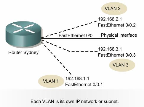
41 . Inter-VLAN Routing - Non-trunk Links / / / /16 One option is to use a separate link to the router for each VLAN instead of trunk links. Each VLAN must have a unique Layer 3 network address assigned. This enables routers to switch packets between VLANs. Although it does load balance between VLANs, it may not make efficient use of links with little traffic. Be sure hosts and routers have the proper IP addresses, associated with the proper VLANs. It is common practice to assign VLAN numbers the same as IP addresses when possible. 41


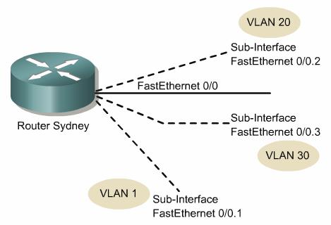
42 . Physical and logical interfaces Subinterfaces on a router can be used to divide a single physical interface into multiple logical interfaces. Lower-end routers such as the 2500 and 1600 do not support subinterfaces. Each physical interface can have up to 65,535 logical interfaces. Rtr(config)#interface fastethernet port/interface.subinterface 42
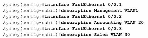
43 Configure subinterface 43
44 . Inter-VLAN Routing - Trunk Links / / / / /16 Rtr(config)#interface fastethernet 0/1.1 Rtr(config-subif)#description VLAN 1 Rtr(config-subif)#encapsulation dot1q 1 Rtr(config-subif)#ip address We will talk about VLAN 1 and the Management VLAN in a moment. It is recommended that VLAN 1 is not used for either Management traffic or user traffic. 44
45 . Inter-VLAN Routing - Trunk Links / / / /16 Rtr(config)#interface fastethernet 0/1.10 Rtr(config-subif)#description Management VLAN 10 Rtr(config-subif)#encapsulation dot1q 10 Rtr(config-subif)#ip address Rtr(config)#interface fastethernet 0/1.20 Rtr(config-subif)#description Management VLAN 20 Rtr(config-subif)#encapsulation dot1q 20 Rtr(config-subif)#ip address
46 Management VLAN For more information regarding VLAN 1, Management VLAN, default VLAN and the Native VLAN, see my article on my web site, NativeVLAN.pdf. This article will help explain the various types of VLANS and attempt to clear up some of this confusion. By default, all Ethernet interfaces on Cisco switches are on VLAN 1. On Catalyst switches all of these VLANs listed above default to VLAN 1, which can add to the difficulty of understanding their differences. 46
47 Management VLAN We won t go into detail here but here are some guidelines. Notice that User VLANs have been configured for VLANs other than VLAN 1. The management VLAN refers to a separate VLAN for your switches and routers. This helps ensure access to these devices when another VLAN is experiencing problems. 47
48 Summary By default, VLAN 1 is the native VLAN and should only be used to carry control traffic, CDP, VTP, PAgP, and DTP. This information is transmitted across trunk links untagged. User VLANs should not include the native VLAN, VLAN 1. This information will be sent as tagged frames across VLAN trunks. The Management VLAN should be a VLAN separate from the user VLANs and should not be the native VLAN. This will insure access to networking devices in case of problems with the network. The subinterface on the router that is used to send and receive native VLAN traffic must be configured with the native option on the encapsulation interface command. This will let the router know that any frames coming in untagged belong to that subinterface and are a member of VLAN 1, the native VLAN. This is assuming that the native VLAN is the VLAN 1, the default native VLAN. 48
49 Ch. 1 Scaling IP Addresses NAT/PAT CCNA 4 version 3.0 Rick Graziani Cabrillo College 1
50 Overview Identify private IP addresses as described in RFC 1918 Discuss characteristics of NAT and PAT Explain the benefits of NAT Explain how to configure NAT and PAT, including static translation, dynamic translation, and overloading Identify the commands used to verify NAT and PAT configuration List the steps used to troubleshoot NAT and PAT configuration Discuss the advantages and disadvantages of NAT Describe the characteristics of DHCP Explain the differences between BOOTP and DHCP Explain the DHCP client configuration process Configure a DHCP server Verify DHCP operation Troubleshoot a DHCP configuration Explain DHCP relay requests 2
51 IP scaling solutions rapid growth of the Internet would have exhausted the current supply of IP addresses several solutions are as follows: NAT (Network Address Translation :RFC 1631) DHCP (Dynamic Host Configuration Protocol ) private IP addresses as described in RFC

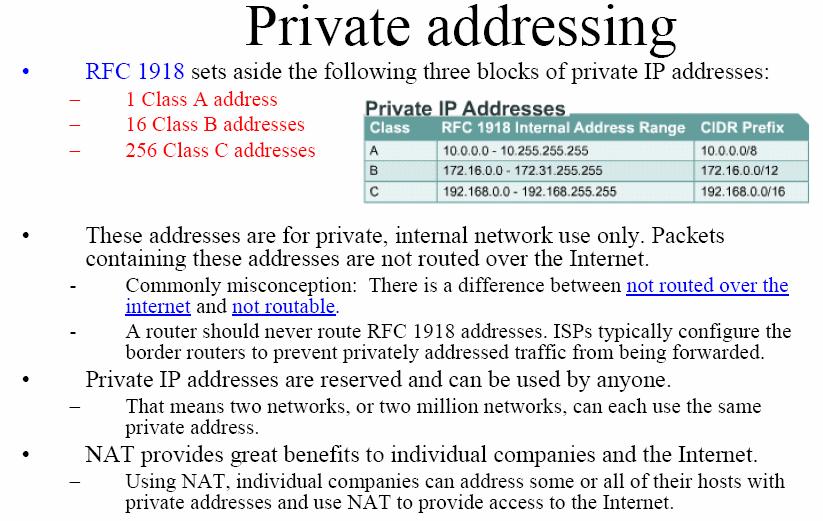
52 Private addressing : /12 Where does the /12 come from? 12 bits in common /12 4
53 5
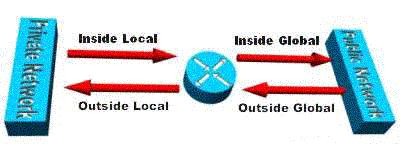
54 Introducing NAT and PAT NAT is designed to conserve IP addresses and enable networks to use private IP addresses on internal networks. These private, internal addresses are translated to routable, public addresses. NAT, as defined by RFC 1631, is the process of swapping one address for another in the IP packet header. In practice, NAT is used to allow hosts that are privately addressed to access the Internet. NAT translations can occur dynamically or statically. The most powerful feature of NAT routers is their capability to use port address translation (PAT), which allows multiple inside addresses to map to the same global address. This is sometimes called a many-to-one NAT. 6

55 Stub network A NAT enabled device typically operates at the border of a stub network. The border gateway router performs the NAT process, translating the internal private address of a host to a public, external routable address. 7

56 NAT Example 8
57 NAT Example 1 2 DA SA DA SA Data Data IP Header 1 2 IP Header The translation from Private source IP address to Public source IP address. 9
58 NAT Example


59 NAT Example 4 3 DA SA DA SA Data Data 4 IP Header IP Header Translation back, from Public destination IP address to Private destination IP address. 3 11

60 NAT Example NAT allows you to have more than your allocated number of IP addresses by using RFC 1918 address space with smaller mask. However, because you have to use your Public IP addresses for the Internet, NAT still limits the number of hosts you can have access the Internet at any one time (depending upon the number of hosts in your public network mask.) 12
61 Major NAT features NAT translations can be used for a variety of purposes and can be either dynamically or statically assigned. Static NAT is designed to allow one-to-one mapping of local and global addresses. This is particularly useful for hosts which must have a consistent address that is accessible from the Internet. These internal hosts may be enterprise servers or networking devices. Dynamic NAT is designed to map a private IP address to a public address. Any IP address from a pool of public IP addresses is assigned to a network host. The dynamic also perform one-to-one mapping. This is particularly useful for hosts which DO NOT NEED to have a consistent address. 13

62 PAT Port Address Translation PAT (Port Address Translation) allows you to use a single Public IP address and assign it up to 65,536 inside hosts per IP address (4,000 is more realistic). The port number is encoded in 16 bits. PAT modifies the TCP/UDP source port to track inside Host addresses. Tracks and translates SA, DA and SP (which uniquely identifies each connection) for each stream of traffic. 14
63 PAT Port Address Translation Overloading, or Port Address Translation (PAT), maps multiple private IP addresses to a single public IP address. Multiple addresses can be mapped to a single address because each private address is tracked by a port number. PAT uses unique source port numbers on the inside global IP address to distinguish between translations. The port number is encoded in 16 bits. The total number of internal addresses that can be translated to one external address could theoretically be as high as 65,536 per IP address. Realistically, the number of ports that can be assigned a single IP address is around PAT will attempt to preserve the original sourceport. If this source port is already used, PAT will assign the first available port number starting from the beginning of the appropriate port group 0-511, , or When there are no more ports available and there is more than one external IP address configured, PAT moves to the next IP address to try to allocate the original source port again. This process continues until it runs out of available ports and external IP addresses. 15
64 PAT Example NAT/PAT table maintains translation of: DA, SA, SP DA SA DP SP DA SA DP SP Data Data IP Header TCP/UDP Header 1 2 IP Header TCP/UDP Header DA SA DP SP DA SA DP SP Data Data IP Header TCP/UDP Header IP Header TCP/UDP Header 16

65 PAT Example NAT/PAT table maintains translation of: SA (DA), DA (SA), DP (SP) DA SA DP SP DA SA DP SP Data Data IP Header TCP/UDP Header 4 3 IP Header TCP/UDP Header DA SA DP SP DA SA DP SP Data Data IP Header TCP/UDP Header IP Header TCP/UDP Header 17
66 PAT Port Address Translation With PAT a multiple private IP addresses can be translated by a single public address (many-to-one translation). This solves the limitation of NAT which is one-to-one translation. 18
67 PAT Port Address Translation DA SA DP SP DA SA DP SP Data Data IP Header TCP/UDP Header 1 2 IP Header TCP/UDP Header DA SA DP SP DA SA DP SP Data Data IP Header TCP/UDP Header IP Header TCP/UDP Header From CCNP 2 curriculum As long as the inside global port numbers are unique for each inside local host, NAT overload will work. For example, if the host at and both use TCP port 1234, the NAT router can create the extended table entries mapping :1234 to :1234 and :1234 to :1235. In fact, NAT implementations do not necessarily try to preserve the original port number. 19
68 Major NAT and PAT benefits NAT offers the following benefits: Eliminates reassigning each host a new IP address when changing to a new ISP. Conserves addresses through application port-level multiplexing. With PAT, internal hosts can share a single public IP address for all external communications. Example: home linksys router In this type of configuration, very few external addresses are required to support many internal hosts, thereby conserving IP addresses. Protects network security. Because private networks do not advertise their addresses or internal topology, they remain reasonably secure when used in conjunction with NAT to gain controlled external access. 20
69 Configuring 21
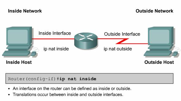
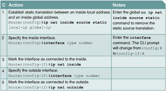
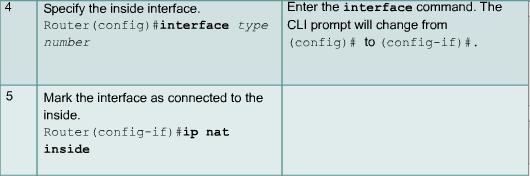
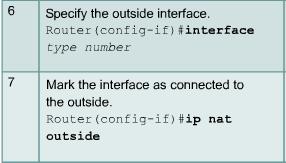
70 Configuring Static Translation Router(config)#ip nat inside source static local-ip global-ip Establishes static translation between an inside local address and an inside global address Router(config-if)#ip nat inside Marks the interface as connected to the inside Router(config-if)#ip nat outside Marks the interface as connected to the outside 22
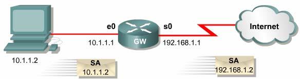
71 Configuring Static NAT Router(config)#ip nat inside source static Router(config)#interface s0 Router(config-if)#ip nat outside Router(config-if)#interface e0 Router(config-if)#ip nat inside 23
72 Configuring Static NAT 24

73 Configuring Static NAT 25
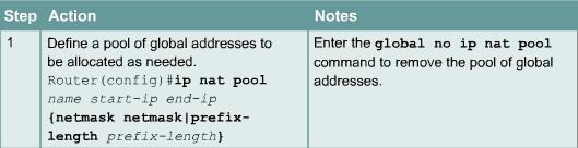
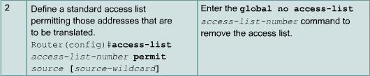
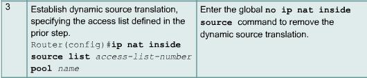
74 Configuring Dynamic Translation Router(config)#ip nat pool name start-ip end-ip {netmask netmask prefix-length prefix-length} Defines a pool of global addresses to be allocated as needed Router(config)#access-list access-list-number permit source [source-wildcard] Defines a standard IP access list permitting those inside local addresses that are to be translated Router(config)#ip nat inside source list access-list-number pool name Establishes dynamic source translation, specifying the access list defined in the prior step 26
75 Configuring Dynamic NAT 27

76 Configuring Dynamic NAT The network address space you have received from ARIN or your ISP is /24. nat-pool /24 to /24 In ISP s routing table: /24 via ISP Translate to these outside addresses Start here Source IP address must match here 28
77 29

78 Configure PAT Overloading NAT 30


79 Configure PAT Overloading NAT is the address your ISP has assigned you. Instead of a host, you put a router there, running PAT so you can have multiple hosts share that same address In this example a single Public IP addresses is used, using PAT, source ports, to differentiate between connection streams. 31
80 Configure PAT Overloading NAT 32

81 Configure PAT Overload This is a different example, using the IP address of the outside interface instead specifying an IP address 33

82 NAT/PAT Clear Commands 34

83 Verifying NAT/PAT 35
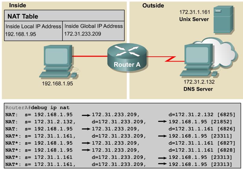
84 Troubleshooting NAT/PAT 36


85 Issues with NAT/PAT NAT also forces some applications that use IP addressing to stop functioning because it hides end-to-end IP addresses. Applications that use physical addresses instead of a qualified domain name will not reach destinations that are translated across the NAT router. Sometimes, this problem can be avoided by implementing static NAT mappings. 37
Scaling IP Addresses DHCP CCNA 4
 Scaling IP Addresses DHCP CCNA 4 Note to instructors If you have downloaded this presentation from the Cisco Networking Academy Community FTP Center, this may not be my latest version of this PowerPoint.
Configuring VLANs. Understanding VLANs CHAPTER
 CHAPTER 10 This chapter describes how to configure normal-range VLANs (VLAN IDs 1 to 1005) and extended-range VLANs (VLAN IDs 1006 to 4094) on the switch. It includes information about VLAN membership
Configuring VLANs. Understanding VLANs CHAPTER
 CHAPTER 12 This chapter describes how to configure normal-range VLANs (VLAN IDs 1 to 1005) and extended-range VLANs (VLAN IDs 1006 to 4094) on the switch. It includes information about VLAN membership
Configuring VLANs. Understanding VLANs CHAPTER
 CHAPTER 11 This chapter describes how to configure normal-range VLANs (VLAN IDs 1 to 1005) and extended-range VLANs (VLAN IDs 1006 to 4094) on your Catalyst 3550 switch. It includes information about VLAN
Configuring VLANs. Understanding VLANs CHAPTER
 CHAPTER 14 This chapter describes how to configure normal-range VLANs (VLAN IDs 1 to 1005) and extended-range VLANs (VLAN IDs 1006 to 4094) on the Catalyst 3750 switch. It includes information about VLAN
Configuring VLANs. Understanding VLANs CHAPTER
 CHAPTER 9 This chapter describes how to configure normal-range VLANs (VLAN IDs 1 to 1005) and extended-range VLANs (VLAN IDs 1006 to 4094). It includes information about VLAN membership modes, VLAN configuration
Configuring VTP. Understanding VTP CHAPTER
 CHAPTER 14 This chapter describes how to use the VLAN Trunking Protocol (VTP) and the VLAN database for managing VLANs with the Catalyst 3750 switch. Unless otherwise noted, the term switch refers to a
Chapter 3: VLANs. Routing & Switching
 Chapter 3: VLANs Routing & Switching VLAN Definitions A VLAN is a logical partition of a Layer 2 network. VLANs logically group hosts, regardless of physical location. Multiple partitions can be created,
Configuring VLANs. Understanding VLANs CHAPTER
 CHAPTER 14 This chapter describes how to configure normal-range VLANs (VLAN IDs 1 to 1005) and extended-range VLANs (VLAN IDs 1006 to 4094). It includes information about VLAN modes and the VLAN Membership
Configuring VLANs. Understanding VLANs CHAPTER
 CHAPTER 16 This chapter describes how to configure normal-range VLANs (VLAN IDs 1 to 1005) and extended-range VLANs (VLAN IDs 1006 to 4094) on your Catalyst 2950 or Catalyst 2955 switch. It includes information
Maintaining Specific VLAN Identification. Comparing ISL and 802.1Q. VLAN Trunking
 Maintaining Specific VLAN Identification Specifically developed for multi-vlan interswitch communications Places a unique identifier in each frame Functions at Layer 2 2003, Cisco Systems, Inc. All rights
3/22/2016 ดร. ธน ญช ย ตร ภาค. Floor 4 : การตลาด 20 เคร อง. Floor 3 : งานบ คคล 10 เคร อง. Floor 2 : งานขาย 15 เคร อง. Floor 1 : การเง น 20 เคร อง
 ดร. ธน ญช ย ตร ภาค 1 Floor 4 : การตลาด 20 เคร อง Floor 3 : งานบ คคล 10 เคร อง Floor 2 : งานขาย 15 เคร อง Floor 1 : การเง น 20 เคร อง 2 1 Floor 4 : การตลาด 20 เคร อง การเง น 3 เคร อง Floor 3 : งานบ คคล
Configuring VTP. Understanding How VTP Works CHAPTER
 CHAPTER 13 This chapter describes how to configure the VLAN Trunking Protocol (VTP) on the Cisco 7600 series routers. For complete syntax and usage information for the commands used in this chapter, refer
VLANs. Traditional Campus Networks. Performance Issues. Broadcast Issues. Bridges terminate collision domains
 Traditional Campus Networks Broadcast Domain VLANs Collision Domain 1 Collision Domain 2 Bridges terminate collision domains 2003, Cisco Systems, Inc. All rights reserved. 2-1 2003, Cisco Systems, Inc.
VLANs. 2003, Cisco Systems, Inc. All rights reserved. 2-1
 VLANs 2003, Cisco Systems, Inc. All rights reserved. 2-1 Traditional Campus Networks Broadcast Domain Collision Domain 1 Collision Domain 2 Bridges terminate collision domains 2003, Cisco Systems, Inc.
VLANs. 2003, Cisco Systems, Inc. All rights reserved. 2-1
 VLANs 2003, Cisco Systems, Inc. All rights reserved. 2-1 Traditional Campus Networks Broadcast Domain Collision Domain 1 Collision Domain 2 Bridges terminate collision domains 2003, Cisco Systems, Inc.
Lab 5: Inter-VLANs Routing
 Lab 5: Inter-VLANs Routing Network Topology:- Device Interface IP Address Subnet Mask Gateway/Clock Rate Fa 0/0.10 10.5.0.1 255.255.255.192 ----- R1 Fa 0/0.20 10.6.0.1 255.255.255.192 ----- Fa 0/0.30 10.10.0.1
Understanding and Configuring VTP
 27 CHAPTER This chapter describes the VLAN Trunking Protocol (VTP) on the Catalyst 4500 series switch. It also provides guidelines, procedures, and configuration examples. This chapter includes the following
For information about configuring these settings from Cluster Management Suite (CMS), refer to the online help.
, refer to the online help.") Configuring VLANs This chapter provides information about configuring virtual LANs (VLANs). It includes command-line interface (CLI) procedures for using commands that have been specifically created or
Configuring VLANs This chapter provides information about configuring virtual LANs (VLANs). It includes command-line interface (CLI) procedures for using commands that have been specifically created or
Configuring VTP. Understanding VTP CHAPTER
 CHAPTER 15 This chapter describes how to use the VLAN Trunking Protocol (VTP) and the VLAN database for managing VLANs with the Catalyst 3560 switch. For complete syntax and usage information for the commands
Configuring VLANs. Understanding VLANs CHAPTER
 7 CHAPTER This chapter describes how to configure normal-range VLANs (VLAN IDs 1 to 1005) and extended-range VLANs (VLAN IDs 1006 to 4094) on the Cisco MWR 2941 router. It includes information about VLAN
Configuring VLANs. Understanding VLANs CHAPTER
 CHAPTER 11 This chapter describes how to configure normal-range VLANs (VLAN IDs 1 to 1005) and extended-range VLANs (VLAN IDs 1006 to 4094) on the Cisco ME 3400 Ethernet Access switch. It includes information
Chapter 3. Virtual Local Area Networks (VLANs) Part II
 Part II") Chapter 3 Virtual Local Area Networks (VLANs) Part II CCNA3-1 Chapter 3-2 Note for Instructors These presentations are the result of a collaboration among the instructors at St. Clair College in Windsor,
Chapter 3 Virtual Local Area Networks (VLANs) Part II CCNA3-1 Chapter 3-2 Note for Instructors These presentations are the result of a collaboration among the instructors at St. Clair College in Windsor,
Configuring VLANs. Finding Feature Information. Prerequisites for VLANs
 Finding Feature Information, page 1 Prerequisites for VLANs, page 1 Restrictions for VLANs, page 2 Information About VLANs, page 2 How to Configure VLANs, page 7 Monitoring VLANs, page 19 Where to Go Next,
Switches running the LAN Base feature set support only static routing on SVIs.
 Finding Feature Information, on page 1 Prerequisites for VLANs, on page 1 Restrictions for VLANs, on page 2 Information About VLANs, on page 2 How to Configure VLANs, on page 6 Monitoring VLANs, on page
Internetwork Expert s CCNP Bootcamp. VLANs, Trunking, & VTP. VLANs Overview
 Internetwork Expert s CCNP Bootcamp VLANs, Trunking, & VTP http:// VLANs Overview Virtual Local Area Network Hosts in the same VLAN share the same broadcast domain Switches create a separate CAM table
Configuring VLAN Trunks
 Finding Feature Information, page 1 Prerequisites for VLAN Trunks, page 1 Information About VLAN Trunks, page 2 How to Configure VLAN Trunks, page 5 Configuration Examples for VLAN Trunking, page 20 Where
VLANs and Trunking C H A P T E R. 6-1: VLAN Configuration. Section 6-1
 C H A P T E R 6 Section 6-1 VLANs and Trunking See the following sections for configuration information about these topics: 6-1: VLAN Configuration Describes the method for configuring, creating, and configuring
Configuring VTP. Understanding How VTP Version 1 and Version 2 Work CHAPTER
 10 CHAPTER This chapter describes how to configure the VLAN Trunking Protocol (VTP) on the Catalyst 6500 series switches For complete syntax and usage information for the commands that are used in this
VLAN Configuration. Understanding VLANs CHAPTER
 CHAPTER 11 This chapter describes how to configure normal-range VLANs (VLAN IDs 1 to 1005) and extended-range VLANs (VLAN IDs 1006 to 4094) on the CGR 2010 ESM. It includes information about VLAN membership
Implement VTP. LAN Switching and Wireless Chapter 4 Modified by Tony Chen 10/01/2008
 Implement VTP LAN Switching and Wireless Chapter 4 Modified by Tony Chen 10/01/2008 ITE I Chapter 6 2006 Cisco Systems, Inc. All rights reserved. Cisco Public 1 Notes: If you see any mistake on my PowerPoint
Lab Catalyst 2950T and 3550 Series VTP Domain and VLAN Trunking
 Lab 2.9.2 Catalyst 2950T and 3550 Series VTP Domain and VLAN Trunking Objective Configure a VLAN trunk between two Cisco Catalyst WS-C2950T-24-EI switches and a Cisco Catalyst WS-C3550-24-EMI switch in
Configuring VLANs. Finding Feature Information. Prerequisites for VLANs
 Finding Feature Information, page 1 Prerequisites for VLANs, page 1 Restrictions for VLANs, page 2 Information About VLANs, page 2 How to Configure VLANs, page 8 Monitoring VLANs, page 22 Where to Go Next,
The following graphic shows a single switch VLAN configuration.
 7.1. VLAN A Virtual LAN (VLAN) can be defined as: Broadcast domains defined by switch port rather than network address. A grouping of devices based on service need, protocol, or other criteria rather than
Interconnecting Cisco Networking Devices Part 2 (ICND2 v3.0)
") Interconnecting Cisco Networking Devices Part 2 (ICND2 v3.0) Cisco 200-105 Dumps Available Here at: /cisco-exam/200-105-dumps.html Enrolling now you will get access to 170 questions in a unique set of
Interconnecting Cisco Networking Devices Part 2 (ICND2 v3.0) Cisco 200-105 Dumps Available Here at: /cisco-exam/200-105-dumps.html Enrolling now you will get access to 170 questions in a unique set of
VLAN Trunking Protocol (VTP)
") 24 CHAPTER Prerequisites for VTP, page 24-1 Restrictions for VTP, page 24-1 Information About VTP, page 24-2 Default Settings for VTP, page 24-9 How to Configure VTP, page 24-10 For complete syntax and
24 CHAPTER Prerequisites for VTP, page 24-1 Restrictions for VTP, page 24-1 Information About VTP, page 24-2 Default Settings for VTP, page 24-9 How to Configure VTP, page 24-10 For complete syntax and
Lab Catalyst 2950T and 3550 Series VTP Domain and VLAN Trunking
 Lab 2.3.7.1 Catalyst 2950T and 3550 Series VTP Domain and VLAN Trunking Objective Configure a VLAN trunk between two Cisco Catalyst WS-C2950T-24-EI switches and a Cisco Catalyst WS-C3550-24-EMI switch
Configuring IEEE 802.1Q Tunneling and Layer 2 Protocol Tunneling
 CHAPTER 14 Configuring IEEE 802.1Q Tunneling and Layer 2 Protocol Tunneling With Release 12.1(13)E and later, the Catalyst 6500 series switches support IEEE 802.1Q tunneling and Layer 2 protocol tunneling.
Chapter 7. IP Addressing Services. IP Addressing Services. Part I
 Chapter 7 IP Addressing Services Part I CCNA4-1 Chapter 7-1 IP Addressing Services Dynamic Host Configuration Protocol (DHCP) CCNA4-2 Chapter 7-1 Dynamic Host Configuration Protocol (DHCP) Every device
PASS4TEST IT 인증시험덤프전문사이트
 PASS4TEST IT 인증시험덤프전문사이트 http://www.pass4test.net 일년동안무료업데이트 Exam : 640-802 Title : Cisco Certified Network Associate(CCNA) Vendors : Cisco Version : DEMO 1 / 10 Get Latest & Valid 640-802 Exam's Question
Configuring IEEE 802.1Q Tunneling
 CHAPTER 26 This chapter describes how to configure IEEE 802.1Q tunneling in Cisco IOS Release 12.2SX. For complete syntax and usage information for the commands used in this chapter, see the Cisco IOS
Chapter 2 Lab 2-1, Static VLANS, VLAN Trunking, and VTP Domains and Modes
 Chapter 2 Lab 2-1, Static VLANS, VLAN Trunking, and VTP Domains and Modes Topology Objectives Background Set up a VTP domain. Create and maintain VLANs. Configure ISL and 802.1Q trunking. VLANs logically
Interconnecting networks with switches. Virtual Local Area Networks (VLAN)
") 1 Interconnecting networks with switches. Virtual Local Area Networks (VLAN) Experimental Development Exercise 1: Creating VLANs and trunk links using the 802.1Q protocol The aims of this exercise are:
1 Interconnecting networks with switches. Virtual Local Area Networks (VLAN) Experimental Development Exercise 1: Creating VLANs and trunk links using the 802.1Q protocol The aims of this exercise are:
Configuring IEEE 802.1Q and Layer 2 Protocol Tunneling
 CHAPTER 8 Configuring IEEE 802.1Q and Layer 2 Protocol Tunneling Virtual private networks (VPNs) provide enterprise-scale connectivity on a shared infrastructure, often Ethernet-based, with the same security,
Configuring Private VLANs
 CHAPTER 15 This chapter describes how to configure private VLANs on the Cisco 7600 series routers. Note For complete syntax and usage information for the commands used in this chapter, refer to the Cisco
Upon completion of this chapter, you will be able to perform the following tasks: Identify what a VLAN is and how it operates. Configure a VLAN to
 Upon completion of this chapter, you will be able to perform the following tasks: Identify what a VLAN is and how it operates. Configure a VLAN to improve network performance. Identify what role the switch
CCNA Cisco Certified Network Associate CCNA (v3.0)
") 200-125 - CCNA Cisco Certified Network Associate CCNA (v3.0) 1.What is one benefit of PVST+? A. PVST+ supports Layer 3 load balancing without loops. B. PVST+ reduces the CPU cycles for all the switches
200-125 - CCNA Cisco Certified Network Associate CCNA (v3.0) 1.What is one benefit of PVST+? A. PVST+ supports Layer 3 load balancing without loops. B. PVST+ reduces the CPU cycles for all the switches
the larger the number of users and devices, the more broadcasts and packets each switch must handle.
 VLANs Introduction By default, routers allow broadcasts to occur only within the originating network, while switches forward broadcasts to all segments. Flat network = one broadcast domain. that the largest
Lab Catalyst 2950T and 3550 Series Static VLANS
 Lab 2.9.1 Catalyst 2950T and 3550 Series Static VLANS Objective Create and maintain VLANs on a Cisco Catalyst 2950T or 3550 series Ethernet switch using the command-line interface (CLI) mode. Scenario
CHAPTER 1: VLANS. Routing & Switching
 CHAPTER 1: VLANS Routing & Switching CHAPTER 1 1.1 VLAN Segmentation 1.2 VLAN Implementation 1.3 VLAN Security and Design 1.4 Summary CHAPTER 1 : OBJECTIVES Explain the purpose of VLANs in a switched network.
Configuring IEEE 802.1Q Tunneling and Layer 2 Protocol Tunneling
 9 CHAPTER Configuring IEEE 802.1Q Tunneling and Layer 2 Protocol Tunneling Virtual private networks (VPNs) provide enterprise-scale connectivity on a shared infrastructure, often Ethernet-based, with the
VLANs. CCNA Exploration Semester 3 Chapter Sep-13
 VLANs CCNA Exploration Semester 3 Chapter 3 1 Topics The role of VLANs in a network Trunking VLANs Configure VLANs on switches Troubleshoot common VLAN problems 2 Semester 3 LAN Design Basic Switch Concepts
1. Which two statements are true about VLAN implementation? (Choose two.)
") CCNA 2 Chapter 3 v5.0 Exam Answers 2015 (100%) 1. Which two statements are true about VLAN implementation? (Choose two.) The size of the collision domain is reduced. The number of required switches in
CCNA 2 Chapter 3 v5.0 Exam Answers 2015 (100%) 1. Which two statements are true about VLAN implementation? (Choose two.) The size of the collision domain is reduced. The number of required switches in
Configuring SPAN and RSPAN
 24 CHAPTER This chapter describes how to configure Switched Port Analyzer (SPAN) and Remote SPAN (RSPAN) on your Catalyst 2950 or Catalyst 2955 switch. Note For complete syntax and usage information for
Configuring SPAN and RSPAN
 CHAPTER 32 This chapter describes how to configure Switched Port Analyzer (SPAN) and Remote SPAN (RSPAN) on the Catalyst 3750-X or 3560-X switch. Unless otherwise noted, the term switch refers to a Catalyst
Configuring Private VLANs
 36 CHAPTER This chapter describes private VLANs (PVLANs) on Catalyst 4500 series switches. It also provides restrictions, procedures, and configuration examples. This chapter includes the following major
Cisco Exploration 3 Module 3 LAN Switching and Wireless Jim Johnston Class Notes September 9, 2008
 Cisco Exploration 3 Module 3 LAN Switching and Wireless Jim Johnston Class Notes September 9, 2008 VLAN is a logically separate IP subnetwork. This allows multiple networks to exist on a switch and provide
Configuring SPAN and RSPAN
 Finding Feature Information, page 1 Prerequisites for SPAN and RSPAN, page 1 Restrictions for SPAN and RSPAN, page 2 Information About SPAN and RSPAN, page 3 How to Configure SPAN and RSPAN, page 14 Monitoring
Lab - Troubleshooting VLAN Configurations (Instructor Version Optional Lab)
") (Instructor Version Optional Lab) Instructor Note: Red font color or gray highlights indicate text that appears in the instructor copy only. Optional activities are designed to enhance understanding and/or
(Instructor Version Optional Lab) Instructor Note: Red font color or gray highlights indicate text that appears in the instructor copy only. Optional activities are designed to enhance understanding and/or
Lab 6.4.1: Basic Inter-VLAN Routing
 Topology Diagram Addressing Table Device (Hostname) Interface IP Address Subnet Mask Default Gateway S1 VLAN 99 172.17.99.11 255.255.255.0 172.17.99.1 S2 VLAN 99 172.17.99.12 255.255.255.0 172.17.99.1
Extending Switched Networks with Virtual LANs. 2000, Cisco Systems, Inc. 7-1
 Extending Switched Networks with Virtual LANs 2000, Cisco Systems, Inc. 7-1 Objectives Upon completion of this chapter, you will be able to perform the following tasks: Configure a VLAN Configure VLAN
Configuring SPAN and RSPAN
 34 CHAPTER This chapter describes how to configure the Switched Port Analyzer (SPAN) and Remote SPAN (RSPAN) on the Catalyst 4500 series switches. SPAN selects network traffic for analysis by a network
Configuring NAT for IP Address Conservation
 This module describes how to configure Network Address Translation (NAT) for IP address conservation and how to configure the inside and outside source addresses. This module also provides information
Configuring VLANs CHAPTER
 CHAPTER 8 This chapter describes how to configure your access point to operate with the VLANs set up on your wired LAN. These sections describe how to configure your access point to support VLANs: Understanding
CCNA Cisco Certified Network Associate CCNA (v3.0)
") CCNA Cisco Certified Network Associate CCNA (v3.0) Cisco 200-125 Dumps Available Here at: /cisco-exam/200-125-dumps.html Enrolling now you will get access to 455 questions in a unique set of 200-125 dumps
CCNA Cisco Certified Network Associate CCNA (v3.0) Cisco 200-125 Dumps Available Here at: /cisco-exam/200-125-dumps.html Enrolling now you will get access to 455 questions in a unique set of 200-125 dumps
Catalyst 1900 Series and Catalyst 2820 Series Enterprise Edition Software Configuration Guide
 INDEX A allowed list, VLAN 2-28 to 2-29 ATM 2-5 firmware upgrade B-5 to B-7 LANE trunk connections 1-4 module 2-9, 2-13, 2-23 networks 2-5 trunk 2-4, 2-14 B bridge groups 3-15 bridge number 2-10 Bridge
Table of Contents. Cisco Using One DHCP Server for Voice and Data Networks
 Table of Contents Using One DHCP Server for Voice and Data Networks1 Document ID: 19580..1 Introduction.1 Prerequisites1 Requirements1 Components Used..1 Conventions..1 Problem.2 Solution.2 The Network
Configuring EtherChannels and Link-State Tracking
 CHAPTER 37 Configuring EtherChannels and Link-State Tracking This chapter describes how to configure EtherChannels on Layer 2 and Layer 3 ports on the switch. EtherChannel provides fault-tolerant high-speed
Note: Use two 2960 switches for ALS1 and ALS2 and two 3560 switches for DLS1 and DLS2
 LAB 2 - Part I - VLANs, VLAN Trunking, and VTP Domains Topology: Objectives Set up a VTP domain. Create and maintain VLANs. Configure 802.1Q trunking. Background VLANs logically segment a network by function,
Lab 6.4.2: Challenge Inter-VLAN Routing
 Lab 6.4.2: Challenge Inter-VLAN Routing Topology Diagram Addressing Table Device (Hostname) Interface IP Address Subnet Mask Default Gateway S1 VLAN 99 192.168.99.11 255.255.255.0 192.168.99.1 S2 VLAN
Configuring Network Address Translation
 Finding Feature Information, on page 1 Network Address Translation (NAT), on page 2 Benefits of Configuring NAT, on page 2 How NAT Works, on page 2 Uses of NAT, on page 3 NAT Inside and Outside Addresses,
Configuring VTP V3. Configuring VTP V3. VTP V3 Overview. Guidelines and Limitation. This chapter contains the following sections:
 This chapter contains the following sections:, page 1 From Cisco NX-OS Release 7.2(0)N1(1), VLAN Trunk Protocol (VTP) V3 supports PVLAN integration, 4K VLAN integration, generic database transport mechanism,
Configuring EtherChannels and Layer 2 Trunk Failover
 35 CHAPTER Configuring EtherChannels and Layer 2 Trunk Failover This chapter describes how to configure EtherChannels on Layer 2 and Layer 3 ports on the switch. EtherChannel provides fault-tolerant high-speed
Exam Implementing Cisco IP Switched Networks (SWITCH)
") Cisco Certified Network Professional (CCNP) Exam 300-115 Implementing Cisco IP Switched Networks (SWITCH) Multiple Choice Questions (2018-05-08 Updated) (300-115) Implementing Cisco IP Switched Networks
Cisco Certified Network Professional (CCNP) Exam 300-115 Implementing Cisco IP Switched Networks (SWITCH) Multiple Choice Questions (2018-05-08 Updated) (300-115) Implementing Cisco IP Switched Networks
Configuring Interface Characteristics
 CHAPTER 10 This chapter defines the types of interfaces on the switch and describes how to configure them. Unless otherwise noted, the term switch refers to a standalone switch and to a switch stack. The
Implement Inter-VLAN Routing. LAN Switching and Wireless Chapter 6 Modified by Tony Chen 11/01/2008
 Implement Inter-VLAN Routing LAN Switching and Wireless Chapter 6 Modified by Tony Chen 11/01/2008 ITE I Chapter 6 2006 Cisco Systems, Inc. All rights reserved. Cisco Public 1 Notes: If you see any mistake
Route between VLANs using a 3560 switch with an internal route processor using Cisco Express Forwarding (CEF).
.") Lab 3- Part I Inter-VLAN routing with a Multilayer Switch Configuration and Management of Networks - 2014 Topology Objective Route between VLANs using a 3560 switch with an internal route processor using
Lab 3- Part I Inter-VLAN routing with a Multilayer Switch Configuration and Management of Networks - 2014 Topology Objective Route between VLANs using a 3560 switch with an internal route processor using
Chapter 4 Lab 4-1, Inter-VLAN Routing with an External Router
 Chapter 4 Lab 4-1, Inter-VLAN Routing with an External Router Topology Objective Background Configure inter-vlan routing using an external router, also known as a router on a stick. Inter-VLAN routing
University of Jordan Faculty of Engineering & Technology Computer Engineering Department Advance Networks Laboratory Exp.4 Inter-VLAN Routing
 University of Jordan Faculty of Engineering & Technology Computer Engineering Department Advance Networks Laboratory 0907529 Exp.4 Inter-VLAN Routing Objectives 1. Describe the three primary options for
Configuring SPAN and RSPAN
 41 CHAPTER This chapter describes how to configure the Switched Port Analyzer (SPAN) and Remote SPAN (RSPAN) on the Catalyst 4500 series switches. SPAN selects network traffic for analysis by a network
Token Ring VLANs and Related Protocols
 Token Ring VLANs and Related Protocols CHAPTER 4 Token Ring VLANs A VLAN is a logical group of LAN segments, independent of physical location, with a common set of requirements. For example, several end
Chapter 2. Switch Concepts and Configuration. Part I
 Chapter 2 Switch Concepts and Configuration Part I CCNA3-1 Chapter 2-1 Note for Instructors These presentations are the result of a collaboration among the instructors at St. Clair College in Windsor,
Configuring Q-in-Q VLAN Tunnels
 This chapter describes how to configure Q-in-Q VLAN tunnels. Finding Feature Information, page 1 Feature History for Q-in-Q Tunnels and Layer 2 Protocol Tunneling, page 1 Information About Q-in-Q Tunnels,
Configuring EtherChannels and Layer 2 Trunk Failover
 28 CHAPTER Configuring EtherChannels and Layer 2 Trunk Failover This chapter describes how to configure EtherChannels on Layer 2 ports on the switch. EtherChannel provides fault-tolerant high-speed links
Lab10: NATing. addressing conflicts, routers must never route private IP addresses.
 Introduction These are reserved private Internet addresses drawn from the three blocks shown in the figure. These addresses are for private, internal network use only. Packets containing these addresses
LAN Troubleshooting. Ethernet Troubleshooting
 CCIE Routing & Switching Advanced Troubleshooting Bootcamp LAN Troubleshooting http:// Ethernet Troubleshooting No Ethernet switching troubleshooting in Troubleshooting Section, but it can be included
Configuring EtherChannels and Link-State Tracking
 30 CHAPTER Configuring EtherChannels and Link-State Tracking This chapter describes how to configure EtherChannels on Layer 2 ports on the Catalyst 2960 switch. EtherChannel provides fault-tolerant high-speed
Configuring SPAN and RSPAN
 Prerequisites for SPAN and RSPAN, page 1 Restrictions for SPAN and RSPAN, page 1 Information About SPAN and RSPAN, page 3 How to Configure SPAN and RSPAN, page 14 Monitoring SPAN and RSPAN Operations,
CHAPTER 1 LAN Design
 CHAPTER 1 LAN Design As a business grows, so does its networking requirements. To keep pace with a business s expansion and new emerging technologies, a network must be designed to scale. A network that
Configuring Link Aggregation
 Information About Link Aggregation, page 1 Restrictions for Link Aggregation, page 1 (GUI), page 3 (CLI), page 4 Verifying Link Aggregation Settings (CLI), page 4 Configuring Neighbor Devices to Support
Lab 8.5.2: Troubleshooting Enterprise Networks 2
 Lab 8.5.2: Troubleshooting Enterprise Networks 2 Topology Diagram Addressing Table Device Interface IP Address Subnet Mask Default Gateway Fa0/0 192.168.10.1 255.255.255.0 N/A R1 Fa0/1 192.168.11.1 255.255.255.0
Question No : 1 Which three of these statements regarding 802.1Q trunking are correct? (Choose three.)
") Volume: 149 Questions Question No : 1 Which three of these statements regarding 802.1Q trunking are correct? (Choose three.) A. 802.1Q native VLAN frames are untagged by default. B. 802.1Q trunking ports
Volume: 149 Questions Question No : 1 Which three of these statements regarding 802.1Q trunking are correct? (Choose three.) A. 802.1Q native VLAN frames are untagged by default. B. 802.1Q trunking ports
Configuring Private VLANs
 Finding Feature Information, on page 1 Prerequisites for Private VLANs, on page 1 Restrictions for Private VLANs, on page 1 Information About Private VLANs, on page 2 How to Configure Private VLANs, on
Configuring SPAN. Understanding SPAN CHAPTER. This chapter describes how to configure Switched Port Analyzer (SPAN) and on the Catalyst 2960 switch.
 and on the Catalyst 2960 switch.") CHAPTER 23 This chapter describes how to configure Switched Port Analyzer (SPAN) and on the Catalyst 2960 switch. Note For complete syntax and usage information for the commands used in this chapter, see
CHAPTER 23 This chapter describes how to configure Switched Port Analyzer (SPAN) and on the Catalyst 2960 switch. Note For complete syntax and usage information for the commands used in this chapter, see
Configuring Link Aggregation on the ML-MR-10 card
 CHAPTER 34 Configuring Link Aggregation on the ML-MR-10 card This chapter applies to the ML-MR-10 card and describes how to configure link aggregation for the ML-Series cards, both EtherChannel and packet-over-sonet/sdh
Lab Configuring EtherChannel
 Topology Addressing Table Objectives Device Interface IP Address Subnet Mask S1 VLAN 99 192.168.99.11 255.255.255.0 S2 VLAN 99 192.168.99.12 255.255.255.0 S3 VLAN 99 192.168.99.13 255.255.255.0 PC-A NIC
CCENT Study Guide. Chapter 11 VLANs and Inter-VLAN Routing
 CCENT Study Guide Chapter 11 VLANs and Inter-VLAN Routing Chapter 11 Objectives The CCENT Topics Covered in this chapter include: 2.0 LAN Switching Technologies 2.4 Configure, verify, and troubleshoot
Troubleshooting VLAN Trunk Protocol (VTP)
") Troubleshooting VLAN Trunk Protocol (VTP) Document ID: 98155 Contents Introduction Prerequisites Requirements Components Used Conventions Understand VTP Configure VTP VTP Troubleshooting and Caveats Unable
Troubleshooting VLAN Trunk Protocol (VTP) Document ID: 98155 Contents Introduction Prerequisites Requirements Components Used Conventions Understand VTP Configure VTP VTP Troubleshooting and Caveats Unable
RealCiscoLAB.com. Configure inter-vlan routing with HSRP to provide redundant, fault-tolerant routing to the internal network.
 RealCiscoLAB.com CCNPv6 SWITCH Hot Standby Router Protocol Topology Objective Background Configure inter-vlan routing with HSRP to provide redundant, fault-tolerant routing to the internal network. Hot
IEEE 802.1Q Configuration
 CHAPTER15 This chapter describes: IP Routing over IEEE 802.1Q InterVLAN Routing and 802.1Q Trunking IP Routing over IEEE 802.1Q This section provides procedures for configuring protocols supported with