CHAPTER I OVERVIEW OF ZIGBEE
|
|
|
- Amelia Jennings
- 5 years ago
- Views:
Transcription
1 CHAPTER I OVERVIEW OF ZIGBEE 1.1 Background ZigBee is a specification for wireless personal area networks (WPANs) operating at 868 MHz, 915 MHz and 2.4 GHz. A WPAN is a personal area network (a network for interconnecting an individual's devices) in which the device connections are wireless. Using ZigBee, devices in a WPAN can communicate at speeds of up to 250 Kbps while physically separated by distances of up to 100 meters in typical circumstances and greater distances in an ideal environment. ZigBee is based on the specification approved by the Institute of Electrical and Electronics Engineers Standards Association (IEEE-SA) [11]. ZigBee provides for high data throughput in applications where the duty cycle is low. This makes ZigBee ideal for home, business and industrial automation where control devices and sensors are commonly used. Such devices operate at low power levels, and this, in conjunction with their low duty cycle (typically 0.1% or less), translates into long battery life. Applications well suited to ZigBee include heating, ventilation and air conditioning (HVAC), lighting systems, fire sensing and the detection, intrusion detection and notification of unusual occurrences. ZigBee is compatible with most topologies including peer-to-peer, star network and mesh networks [41]. 1.2 The Name ZigBee The name ZigBee is derived from the erratic zigging patterns many bees make between flowers when collecting pollen. This is evocative of the invisible webs of connections existing in a fully wireless environment. The standard itself is regulated by a group known as the ZigBee Alliance with over 200 members worldwide [27].
2 1.3 ZigBee Alliance The ZigBee Alliance is an association of companies working together to define an open global standard for making low-power wireless networks. The intended outcome of ZigBee Alliance is to create a specification defining how to build different network topologies with data security features and interoperable application profiles. The association includes companies from a wide spectrum of categories, from chip manufactures to system integration companies. The number of members in the association is rapidly growing and is currently over 200. Among the members one can find Philips, Samsung, Motorola and LG. The first specification was ratified in 2004 and the first generation of ZigBee products had reached the market in A big challenge for the alliance is to make the interoperability to work among different products. To solve this problem, the ZigBee Alliance has defined different profiles, depending on what type of category the product belongs to. For example there is a profile called Home Lightning that exactly defines how different brands of home lightning-products should communicate with each other [28]. 1.4 History of ZigBee ZigBee-style networks began to be conceived about 1998, when many installers realized that both WiFi and Bluetooth were going to be unsuitable for many applications. In particular, many engineers saw a need for self-organizing ad-hoc digital radio networks. The IEEE standard was completed in May In the summer of 2003, Philips Semiconductors, a major mesh network supporter, ceased the investment. Philips Lighting has, however, continued Philips' participation and Philips remains a promoter member on the ZigBee Alliance Board of Directors. The ZigBee Alliance announced in October 2004 that the membership had more than doubled in the preceding year and had grown to more than 100 member companies, in 22 countries. By April 2005 membership had grown to more than 150 companies and by December 2005 membership had passed 200 companies. 2
3 The ZigBee specifications were ratified on 14 December The ZigBee Alliance announces public availability of Specification 1.0 on 13 June 2005, known as ZigBee 2004 Specification. The ZigBee Alliance announces the completion and immediate member availability of the enhanced version of the ZigBee Standard in September 2006, known as ZigBee 2006 Specification. During the last quarter of 2007, ZigBee PRO, the enhanced ZigBee specification was finalized [34]. 1.5 Evolution of Low-Rate Wireless Personal Area Networks (LR-WPAN) Standardization The cellular network was a natural extension of the wired telephony network that became pervasive during the mid-20th century. As the need for mobility and the cost of laying new wires increased, the motivation for a personal connection independent of location to that network also increased. Coverage of large area is provided through (1-2 km) cells that cooperate with their neighbors to create a seemingly seamless network. Examples of standards are GSM, IS-136, IS-95. Cellular standards basically aimed at facilitating voice communications throughout a metropolitan area. Table 1.1: Review of alphabet soup Wireless Personal Area Networks (WPAN) WPANs based on Bluetooth Coexistence of WPAN s and WLAN s High data rates 20Mbps+ on WPAN a High speed PHY enhancements b High speed MAC enhancements Low data rate, simple multi year battery life Mesh Networking 3
4 During the mid-1980s, it turned out that an even smaller coverage area was needed for higher user densities and the emergent data traffic. The IEEE working group for WLANs is formed to create a wireless local area network standard. Whereas IEEE was concerned with features such as Ethernet matching speed, long range (100m), complexity to handle seamless roaming, message forwarding and data throughput of 2-11 Mbps, WPANs are focused on a space around a person or object that typically extends up to 10m in all directions. The focus of WPANs is low-cost, low power, short range and very small size. The IEEE working group is formed to create WPAN standard (see Table 1.1). This group has currently defined three classes of WPANs that are differentiated by data rate, battery drain and quality of service (QoS). The high data rate WPAN (IEEE ) is suitable for multi-media applications that require very high QoS. Medium rate WPANs (IEEE /Bluetooth) will handle a variety of tasks ranging from cell phones to PDA communications and have QoS suitable for voice communications. The low rate WPANs (IEEE /LR-WPAN) is intended to serve a set of industrial, residential and medical applications with very low power consumption and cost requirement not considered by the above WPANs and with relaxed needs for data rate and QoS. The low data rate enables the LR-WPAN to consume very little power [11]. 1.6 ZigBee and IEEE ZigBee technology is a low data rate, low power consumption, low cost, wireless networking protocol targeted towards automation and remote control applications. IEEE committee started working on a low data rate standard a short while later. Then the ZigBee Alliance and the IEEE decided to join forces and ZigBee is the commercial name for this technology. ZigBee is expected to provide low cost and low power connectivity for equipment that needs battery life as long as several months to several years but does not require data transfer rates as high as those enabled by Bluetooth. In addition, ZigBee can be implemented in mesh networks larger than is possible with Bluetooth. ZigBee compliant wireless devices are expected to transmit in the range of meters, depending on the RF 4
5 environment and the power output consumption required for a given application and will operate in the unlicensed RF worldwide (2.4 GHz global, 915 MHz Americas or 868 MHz Europe). The data rate is 250 kbps at 2.4 GHz, 40 kbps at 915 MHz and 20 kbps at 868 MHz. IEEE and ZigBee Alliance have been working closely to specify the entire protocol stack (see Figure 1.1). IEEE focuses on the specification of the lower two layers of the protocol (physical and data link layer). On the other hand, ZigBee Alliance aims to provide the upper layers of the protocol stack (from network to the application layer) for interoperable data networking, security services and a range of wireless home and building control solutions, provide interoperability compliance testing, marketing of the standard, advanced engineering for the evolution of the standard. This will assure consumers to buy products from different manufacturers with confidence that the products will work together. APPLICATION/ PROFILES ZigBee APPLICATION FRAMEWORK NETWORK/SECURITY LAYERS MAC LAYER PHY LAYER IEEE ZigBee Alliance Platform Application ZigBee Platform Stack Silicon Figure 1.1: Protocol stack structure IEEE is now detailing the specification of physical layer (PHY) and medium access layer (MAC) by offering building blocks for different types of networking known as star, mesh and cluster tree. Network routing schemes are designed to ensure power 5
6 conservation and low latency through guaranteed time slots. A unique feature of ZigBee network layer is communication redundancy eliminating single point of failure in mesh networks. Key features of PHY include energy and link quality detection, clear channel assessment for improved coexistence with other wireless networks [5]. 1.7 ZigBee vs. Other Wireless Standards Table 1.2 outlines some of the key characteristics of ZigBee and how it stacks up against other common wireless standards [42]. Table 1.2: ZigBee vs. Other wireless standards Data Rate Range (meters) Networking Topology Operating Frequency Complexity (Device and Application impact) Power Consumption (Battery option and life) Security ZigBee UWB (Ultra IR Bluetooth (Wi-fi) Wide Band) Wireless , 40 and 250 Kbits/s 11 & Kbits/s Mbits/s Mbits/s Mbits/s Kbits/s 4 & 6 Mbits/s < 10 < 10 Ad-hoc, Ad-hoc, Point to Point to peer to peer, very small Hub point star, mesh Networks 868 MHz (Europe) 2.4 and MHz (NA), 2.4 GHz GHz GHz GHz (Global) Point to point nm Low High High Medium Low Very low (low power is a design High Medium Low Low goal) 128 AES plus 64 and 128 application layer bit secutiry encyption 6
7 Other Information Devices can join an existing network in under 30ms Device connection requires 3 5 sec. Device connection requires up to 10 seconds Typical Applications Industrial control and monitoring, sensor networks, building automation, home control and automation toys, games Wireless LAN connectivity, broadband Internet access Wireless connectivity between such as phones, PDA, laptops, headsets Streaming video, home entertainment applications Remote controls, PC, PDA, phone, laptop links ZigBee looks rather like Bluetooth but is simpler, has a lower data rate and spends most of its time snoozing. This characteristic means that a node on a ZigBee network should be able to run for six months to three years on just two AA batteries (see Table 1.3). The operational range of ZigBee is 1-100m compared to 10m for Bluetooth (without a power amplifier). ZigBee sits below Bluetooth in terms of data rate. The data rate of ZigBee is 250 kbps at 2.4 GHz, 40 kbps at 915 MHz and 20 kbps at 868 MHz whereas that of Bluetooth is 1 Mbps. Table 1.3: Comparison between ZigBee and Bluetooth Market Name (Standard) ZigBee ( ) Bluetooth ( ) Application Focus Monitoring & Control Cable Replacement Bandwidth (Hz) Battery Life (days) Network Join Time msec 3 sec Network Size (# of nodes) System Resources 4 kb - 32 kb 250 kb+ Transmission Range (meters) Success Metrics Reliability, Power, Cost Convenience 7
8 ZigBee uses a basic master-slave configuration suited to static star networks of many infrequently used devices that talk via small data packets. It allows up to nodes. Bluetooth s protocol is more complex since it is geared towards handling voice, images and file transfers in ad-hoc networks. Bluetooth devices can support scatternets of multiple smaller non-synchronized networks (piconets) and it only allows up to 7 slave nodes in a basic master-slave piconet set-up. When ZigBee node is powered down, it can wake up and get a packet in around 15 msec. whereas a Bluetooth device would take around 3 sec. to wake up and respond. 1.8 ZigBee Wireless Markets and Applications Table 1.4 [36] shows that ZigBee s markets and its applications. As seen below ZigBee has a big marketing at many sectors in world wide. Table 1.4: ZigBee wireless markets and applications Markets building automation consumer electronics industrial control PC & peripherals personal health care residental / light commercial control Applications security, HVAC, AMR, lighting and access conrtol remote control asset management, process control, energy management mouse, keyboard, Joystick patent monitoring security, HVAC, lighting and access conrtol The biggest marketing partition is the building automation in ZigBee applications. Figure 1.2 shows a typical smart home solutions application using ZigBee [9]. As seen that figure many applications can be performed. 8

 [10].")

9 Figure 1.2: Smart home using ZigBee Zigbee s marketing is growing up speedily and its compound annual growth rate is 63% (see Figure 1.3) [10] $M Figure 1.3: Worldwide IEEE and ZigBee Chipset Revenue 9
10 There has been many researchers and analysts who studied and developed ZigBee based products. Some of the important studies in this field are given below: Remote-controlled home robot server with ZigBee sensor network [13] Recently, interest of general public towards ubiquitous home networking has increased immensely and wireless PAN (personal area network) has attracted strong attentions as short-distance networking solution. Convenience of wireless PAN technology has attracted more attentions over traditional wired home network devices such as Ethernet, PLC and HomePNA since it requires no cabling work. In the future, home servers will be combined with robots to provide functionalities identical to current home service robots as well as to implement more effective and spontaneous servers. In this paper, Choi et al. described a remotely controlled robot for home automation applications, using ZigBee protocol devices. A Wireless solution for greenhouse monitoring and control system based on ZigBee [20] With the rapid development of wireless technologies, it is possible for greenhouses to be equipped with wireless sensor networks due to their low-cost, simplicity and mobility. In this study, the advantages of ZigBee with other two similar wireless networking protocols are compared, e.g. Wi-Fi, Bluetooth and the ZigBee protocol is recommended for greenhouse monitoring and control because of its low-power requirements and the network capacity. ZigBee-based demand-response systems reduce home energy usage [8] Home automation originally evolved to bring whole-house entertainment and comfort control into affluent homes. But the advent of wireless technologies combined with lowpower, low-cost hardware has made home automation networks affordable and easy to install for the average homeowner. Beyond the lifestyle benefits, affordable wireless 10
11 technology has also enabled manufacturers to embed wireless intelligence into a variety of energy conservation and management technologies that will have a huge impact on reducing our energy woes and greenhouse emissions in the near term. Demand response systems for managing energy usage in homes are among the most promising of these new technologies. Households consume one-fifth of the nation's energy each year with 60% of that consumption in the form of electricity. At the same time, utilities are struggling to manage the peak energy demand dilemma, where about 10% of electric generating capacity exists only to be used less than one percent of the time. If energy demand can respond dynamically to the available energy supply, huge cost, reliability and energy efficiency gains can be achieved within homes and the energy grid without having to build additional power plants. Homeowners are ning to adopt wireless home area networks (HANs) to gain not just whole-house entertainment control but also the ability to better manage their energy consumption and this without the expense of traditional wired home automation systems. ZigBee is an ideal candidate in such home energy saving applications. Development of ZigBee based street light control system [16] Industry of street lighting systems are growing rapidly and becoming complex with rapid growth of industry and cities. To control and maintain complex street lighting system more economically, various street light control systems are developed. Nevertheless most of the developed systems have some drawbacks. Therefore new light control systems are going to be developed which can overcome old systems drawbacks. Various street light control systems were surveyed and their characteristics analyzed by Lee. Through these efforts, it was found that common drawbacks of most light control systems are their uneasiness of handling and difficulty of maintenance. To reduce these drawbacks, new street light control system has been designed by using Zigbee communication techniques. ZigBee-based home security system [2] AlertMe offering is a subscription-based security system designed to detect events such as an intruder or a fire and alert users via SMS text messaging or . The Linux-based Hub 11
12 at the core of the system stays in constant touch with sensors and other devices scattered around the home via ZigBee. The Hub in turn communicates via a secure broadband connection to alertme.com 's servers, which then send out alerts to the customer and authorized friends and family members. ZigBee based wireless sensor network fed with sun batteries [15] The goal of this project was the producting of supply voltage required for the PicdemZ card and connected sensors that used the Zigbee based security project in the Department of Electrical & Electronics Engineering of Ege University by Kok. Low-power was a requirement here and thus ZigBee was a suitable protocol. A home security ZigBee network for remote monitoring application [1] Security monitoring systems are popular in home automation and Zigbee is a new industrial standard wireless sensor network. This paper introduces an experimental home security monitoring and alarming system based on the Zigbee technology. It is capable of monitoring door & window magnetic contacts, smoke, gas leak, water flooding and providing simple controls such as turning off the valves and sending alarms to the residential area security network etc. The security alarming system is based on a Zigbee chip and a low power consumption micro-controller. The system uses a control key fob for activating and de-activating the alarm easily, supports web interface so that users can access the system remotely to control, search or review the history record and also offers a LCD panel for simple configuration. The experimental system has been designed and its wireless communication test result shows that the Zigbee wireless network can improve the home security with low power and easy to implement solution. ZigBee-ready modules for sensor networking [6,17] Fully functional ZigBee-ready modules have been designed, implemented and tested by many manufacturers. It is shown that ZigBee is suitable for sensor networking where long battery life, large networks and fast network establishment are the main requirements. 12
13 Multi-stage real time health monitoring via ZigBee in smart homes [3] Dagtas et. al. describe a ZigBee based real-time health monitoring system for use in smart homes. The main advantage of the proposed system was the ability to detect signals wirelessly within a Body Area Network (BAN), low-power and reliable operation. Implementing a ZigBee Protocol Stack and Light Sensor in TinyOS [19] Munk-Stander et. al. describe a ZigBee based protocol stack used in light sensing applications. It is reported that the system had the advantages of low data rate, low power consumption, security and reliability. Even though the implementation is specialized to the light sensor application, the protocol stack in itself can be used to implement many other applications having similar requirements as the ones presented by the authors. ZigBee-based IR remote control repeater and its control message frame format [12] A ZigBee based Infrared (IR) remote control repeater has been designed for consumer applications. Many legacy consumer devices are controlled via IR remote controls. A user needs one IR remote control per one legacy consumer device and has to guarantee the line of sight towards legacy consumer devices. As the ubiquitous home era emerges, all home devices are required to be controllable at anytime and anywhere. To control IR-based legacy consumer devices regardless of the line of sight, a small ZigBee-based IR remote control repeater is attached near the IR receiving part of a legacy consumer device. It receives the control message via ZigBee protocol and converts the received message into IR signal which is transmitted to the legacy consumer device. The designed device has the advantage that a large number of nodes can be connected to the device. Remote monitoring of motor operational data using ZigBee wireless protocol [4] In today s market there is only a slight selection of products in the Heating and AC business that offer wireless technology. The demand for wireless technology that can display a motors status in an HVAC system is essential, especially for motor developers and installers. In this document, the criteria necessary for developing such technology and 13
14 the benefits of developing wireless technology to display and manage a high efficient motor within a furnace, subjects are described. Existing HVAC systems only provide temperature information of the thermostat, which is located in the living room. This requires that technicians search for the furnace, disable the furnace box and diagnose the speed and power of the electrically commutated motor (ECM). It will be a big help for the technicians and homeowners if motor information can be provided at the living room. ZigBee based dynamic control scheme for multiple legacy IR controllable digital consumer devices [21] A universal remote control (URC) unit is an integrated device for controlling many different consumer electronics (CE) home appliances. To control these various CE devices based on infrared (IR) control signal, the URC unit has to have many preprogrammed control codes for controlling them because they are controlled with many different types of IR profile stated with lead code, control code, carrier frequency, duty cycle, duration and so forth. In this paper, a dynamic control scheme for multiple legacy IR controllable digital CE appliances are proposed, which is based on IEEE , especially ZigBee protocol. The proposed scheme uses two main components. One is a URC unit using ZigBee based wireless network technology, WPAN. Another is a Z2IR (ZigBee to IR) conversion module which converts a control message transferred through the ZigBee network into an IR typed control signal. In this scheme, the list of CE devices to be controlled by the proposed URC, called as Z-URC (ZigBee based user remote control) is dynamically reconfigured. The Impact of ZigBee in a biomedical environment [24] Thraning described the impact of the ZigBee technology in a biomedical environment in his thesis. The thesis s focus is the evaluation of possible technologies and solutions for communication between several wireless sensors and a CIP-node with respect to battery capacity, scalability, fail-safety, security and cost in the design of new applications and communication principles. 14
15 ZigBee suitability for wireless sensor networks in logistic telemetry applications [14] There has been a quick development in the wireless network area during the last decade. Mostly these days the focus in the wireless area is on very high speed and long range applications. This application describes how ZigBee is suitable for wireless sensor networks in logistic telemetry applications for global managing and monitoring of goods. The other aim of this thesis was to examine different issues related to ZigBee to see its fitness for logistic telemetry applications like multi-hop routing issues, routing strategies and design requirements. ZigBee is relatively new wireless technology, so there are great deals of promises associated with it. ZigBee for building control wireless sensor Networks [25] Zucatto et. al. describe a method where the stack profile is selected by the ZigBee coordinator and is chosen on the basis of application areas, such as home control, building automation or plant control. Aiming the development of a commercial ZigBee product for home control. In this paper some important aspects of those standards and the main directives of the stack profile and network topology are described. ZigBee-based meter aids energy efficiency [37] An energy saving ZigBee based plug-in electricity meter is described. The device, called the plogg, allows home and building owners to monitor how much electricity is being used by individual appliances and electronic devices so that energy efficiency can be improved. Recent studies by the British government and the Carbon Trust show that people can save 5-15% of the electricity they use by using smart meters to manage energy demands. Remote copy-paste based ZigBee [5] In today s world, the methods for copying data from one computer to another one is not secure. This paper describes how the data can be copied securely between two computers using ZigBee devices. 15
16 CHAPTER 2 IEEE WIRELESS PERSONAL AREA NETWORK, ZIGBEE LAYERS AND SECURITY ZigBee is an IEEE wireless personal area network technology. In this chapter, components of IEEE wireless personal area network, ZigBee s physical, medium access control and routing layers are mentioned. Also given information about ZigBee s security. 2.1 IEEE Wireless Personal Area Network The main features of this standard are network flexibility, low cost, very low power consumption and low data rate. It is developed for applications with relaxed throughput requirements which cannot handle the power consumption of heavy protocol stacks Components of WPAN A ZigBee system consists of several components. The most basic is the device. A device can be a full-function device (FFD) or reduced-function device (RFD). A network shall include at least one FFD, operating as the PAN coordinator. The FFD can operate in three modes: a personal area network (PAN) coordinator, a coordinator or a device. An RFD is intended for applications that are extremely simple and do not need to send large amounts of data. An FFD can communicate with RFDs or FFDs while an RFD can only communicate with an FFD [5] Network Topologies Figure 2.1 shows three types of topologies that ZigBee supports; star topology, peer to peer topology and cluster tree [5]. 16
17 Star Topology In the star topology, the communication is established between devices and a single central controller, called the PAN coordinator. The PAN coordinator may be mains powered while the devices will most likely be battery powered. Applications that benefit from this topology include home automation, personal computer (PC) peripherals, toys and games. Mesh Star Cluster Tree PAN coordinator Full Function Device Reduced Function Device Figure 2.1: Topology models After an FFD is activated for the first time, it may establish its own network and become the PAN coordinator. Each start network chooses a PAN identifier, which is not currently used by any other network within the radio sphere of influence. This allows each star network to operate independently Peer to Peer Topology In peer-to-peer topology, there is also one PAN coordinator. In contrast to star topology, any device can communicate with any other device as long as they are in range of one another. A peer-to-peer network can be ad-hoc, self-organizing and self-healing. 17
18 Applications such as industrial control and monitoring, wireless sensor networks, asset and inventory tracking would benefit from such a topology. It also allows multiple hops to route messages from any device to any other device in the network. It can provide reliability by multipath routing Cluster Tree Topology Cluster-tree network is a special case of a peer-to-peer network in which most devices are FFDs and an RFD may connect to a cluster-tree network as a leave node at the end of a branch. Any of the FFD can act as a coordinator and provide synchronization services to other devices and coordinators. Only one of these coordinators however is the PAN coordinator. The PAN coordinator forms the first cluster by establishing itself as the cluster head (CLH) with a cluster identifier (CID) of zero, choosing an unused PAN identifier and broadcasting beacon frames to neighboring devices. A candidate device receiving a beacon frame may request to join the network at the CLH. If the PAN coordinator permits the device to join, it will add this new device as a child device in its neighbor list. The newly joined device will add the CLH as its parent in its neighbor list and transmitting periodic beacons such that other candidate devices may then join the network at that device. Once application or network requirements are met, the PAN coordinator may instruct a device to become the CLH of a new cluster adjacent to the first one. The advantage of this clustered structure is the increased coverage area at the cost of increased message latency LR-WPAN Device Architecture Figure 2.2 shows an LR-WPAN device [11]. The device comprises a PHY, which contains the radio frequency (RF) transceiver along with its low-level control mechanism and a MAC sublayer that provides access to the physical channel for all types of transfer. The upper layers consists of a network layer, which provides network configuration, manipulation, message routing and application layer, which provides the intended function 18
19 of a device. An IEEE logical link control (LLC) can access the MAC sublayer through the service specific convergence sublayer (SSCS). Upper Layers LLC SSCS MAC PHY Physical Medium Figure 2.2: LR-WPAN device architecture 2.2 Physical Layer The physical layer (PHY) [5] provides two services: the PHY data service and PHY management service interfacing to the physical layer management entity (PLME). The PHY data service enables the transmission and reception of PHY protocol data units (PPDU) across the physical radio channel. The features of the PHY are activation and deactivation of the radio transceiver, energy detection (ED), link quality indication (LQI), channel selection, clear channel assessment (CCA) and transmitting as well as receiving packets across the physical medium. The standard offers two PHY options based on the frequency band. Both are based on direct sequence spread spectrum (DSSS). The data rate is 250 kbps at 2.4 GHz, 40 kbps at 19
20 915 MHz and 20 kbps at 868 MHz. The higher data rate at 2.4 GHz is attributed to a higher-order modulation scheme. Lower frequency provide longer range due to lower propagation losses. Low rate can be translated into better sensitivity and larger coverage area. Higher rate means higher throughput, lower latency or lower duty cycle. This information is summarized in Table 2.1. Table 2.1: Frequency bands and data rates PHY (MHz) Frequency band (MHz) Channel numbering Chip rate (kchips/s) Modulation Bit rate (kb/s) Symbol rate (ksymbol/s) Symbols BPSK Binary BPSK Binary O-QPSK ary Orthogonal There is a single channel between 868 and MHz, 10 channels between and MHz, 16 channels between 2.4 and GHz. Several channels in different frequency bands enables the ability to relocate within spectrum. The standard also allows dynamic channel selection, a scan function that steps through a list of supported channels in search of beacon, receiver energy detection, link quality indication and channel switching. Receiver sensitivities are -85 dbm for 2.4 GHz and -92 dbm for 868/915 MHz. The advantage of 6-8 dbm comes from the advantage of lower rate. The achievable range is a function of receiver sensitivity and transmit power. The maximum transmit power shall conform with local regulations. A compliant device shall have its nominal transmit power level indicated by the PHY parameter Transmit Power The transmitter should be capable of transmitting at least -3 dbm. The device should transmit as low power as possible to reduce interference to other devices and systems. The definition of dbm is shown in Equation 2.1 [18]: 20
21 Power dbm = 10log Power mw 1mW (2.1) Table 2.2 [38] shows that some dbm power equations. Table 2.2: dbm power equations [30] dbm Level Power dbm Level Power dbm Level Power 80 dbm 100 kw 20 dbm 100 mw -20 dbm 10 µw 60 dbm 1 kw 15 dbm 32 mw -30 dbm 1.0 µw 50 dbm 100 W 10 dbm 10 mw -40 dbm 100 nw 40 dbm 10 W 6 dbm 4.0 mw -50 dbm 10 nw 36 dbm 4 W 5 dbm 3.2 mw -60 dbm 1.0 nw 33 dbm 2 W 4 dbm 2.5 mw -70 dbm 100 pw 30 dbm 1 W 3 dbm 2.0 mw -80 dbm 10 pw 27 dbm 500 mw 2 dbm 1.6 mw -100 dbm 0.1 pw 26 dbm 400 mw 1 dbm 1.3 mw -111 dbm pw 25 dbm 316 mw 0 dbm 1.0 mw dbm fw 24 dbm 250 mw -1 dbm 794 µw -174 dbm aw 23 dbm 200 mw -3 dbm 501 µw dbm zw 22 dbm 160 mw -5 dbm 316 µw - dbm 0 W 21 dbm 125 mw -10 dbm 100 µw Receiver Energy Detection (ED) The receiver energy detection (ED) [5] measurement is intended for use by a network layer as part of channel selection algorithm. It is an estimate of the received signal power within the bandwidth of an IEEE channel. No attempt is made to identify or decode signals on the channel. The ED time should be equal to 8 symbol periods. The ED result shall be reported as an 8-bit integer ranging from 0x00 to 0xFF. The minimum ED value (0) shall indicate received power less than 10 db above the specified receiver sensitivity. The range of received power spanned by the ED values shall be at least 40dB. Within this range, the mapping from the received power in decibels to ED values shall be linear with an accuracy of ±6 db. 21
22 2.2.3 Link Quality Indication (LQI) Upon reception of a packet, the PHY sends the PSDU length, PSDU itself and link quality (LQ) in the PD-DATA indication primitive. The LQI [5] measurement is a characterization of the strength and/or quality of a received packet. The measurement may be implemented using receiver ED, a signal-to-noise estimation or a combination of these methods. The use of LQI result is up to the network or application layers. The LQI result should be reported as an integer ranging from 0x00 to 0xff. The minimum and maximum LQI values should be associated with the lowest and highest quality IEEE signals detectable by the receiver and LQ values should be uniformly distributed between these two limits Clear Channel Assessment (CCA) The clear channel assessment (CCA) [5] is performed according to at least one of the following three methods: Energy above threshold. CCA shall report a busy medium upon detecting any energy above the ED threshold. Carrier sense only. CCA shall report a busy medium only upon the detection of a signal with the modulation and spreading characteristics of IEEE This signal may be above or below the ED threshold. Carrier sense with energy above threshold. CCA shall report a busy medium only upon the detection of a signal with the modulation and spreading characteristics of IEEE with energy above the ED threshold PHY Protocol Data Unit (PPDU) Format The PPDU [5] packet structure is illustrated in Table 2.3. Each PPDU packet consists of the following basic components: PHY Header (PHR), which contains frame length information 22
23 Synchronization Header (SHR), which allows a receiving device to synchronize and lock into the bit stream A variable length payload, which carries the MAC sublayer frame. Table 2.3: Format of the PPDU Octets:4 1 1 Variable Preamble SFD Frame length (7 bits) Reserved (1 bit) PSDU SHR PHR PHY payload 2.3 Medium Access Control Layer The Medium Access Control (MAC) layer [6] provides the interface between the PHY layer and the NWK layer. The MAC is responsible for generating beacons and synchronizing the device to the beacons (in a beacon-enabled network). The MAC layer also provides association and disassociation services MAC Frame Structures The IEEE defines 4 MAC frame structures [6]: Beacon frame Data frame Acknowledge frame MAC command frame The beacon frame is used by a coordinator to transmit beacons. The beacons are used to synchronize the clock of all the devices within the same network. The data and acknowledgment frames are used to transmit data and accordingly acknowledge the successful reception of a frame. The MAC commands are transmitted using a MAC command frame. 23
24 The Beacon Frame The structure of a beacon frame [6] is shown in Figure 2.3. The entire MAC frame is used as a payload in a PHY packet. The content of the PHY payload is referred to as the PHY Service Data Unit (PSDU). In the PHY packet, the preamble field is used by the receiver for synchronization. The startof-frame delimiter (SFD) indicates the end of SHR and start of PHR. The frame length specifies the total number of octets in the PHY payload (PSDU). The MAC frame consists of three sections: the MAC header (MHR), the MAC payload and the MAC footer (MFR). The frame control field in the MHR contains information defining the frame type, addressing fields and other control flags. The sequence number specifies the beacon sequence number (BSN). The addressing field provides the source and destination addresses. The auxiliary security header is optional and contains information required for security processing. The MAC payload is provided by the NWK layer. The superframe is a frame bounded by two beacon frames. The superframe is optionally used in a beacon-enabled network and helps define GTSs. The GTS field in the MAC payload determines whether a GTS is used to receive or transmit. Mac Layer Frame Control Sequence Number Adressing Fields Auxiliary Security HDR Superframe Specification GTS Fields Pending Address Fields Beacon Payload FCS MHR MAC Payload MFR PHY Layer Preamble Frame Length SFD PSDU Sequence Reserved SHR PHR PHY Payload Figure 2.3: The MAC Beacon Frame Structure 24
25 The beacon frame is not only used to synchronize the devices in a network but is also used by the coordinator to let a specific device in a network know there is data pending for that device in the coordinator. The device, at its discretion, will contact the coordinator and request that it transmit the data to the device. This is called indirect transmission. The pending address field in the MAC payload contains the address of the devices that have data pending in the coordinator. Every time a device receives a beacon, it will check the pending address field to see if there is data pending for it. The beacon payload field is an optional field that can be used by the NWK layer and is transmitted along with the beacon frame. The receiver uses the Frame Check Sequence (FCS) field to check for any possible error in the received frame The Data Frame The MAC data frame [6] is shown in Figure 2.4. The data payload is provided by the NWK layer. The data in the MAC payload is referred to as the MAC Service Data Unit (MSDU). The fields in this frame are similar to the beacon frame except the superframe, GTS and pending address fields are not present in the MAC data frame. The MAC data frame is referred to as the MAC Protocol Data Unit (MPDU) and becomes the PHY payload. MAC Layer Frame Control Sequence Adressing Number Fields MHR Auxiliary Security HDR Data Payload FCS MAC Payload MFR PHY Layer Preamble Frame Length SFD PSDU Sequence Reserved SHR PHR PHY Payload Figure 2.4: The MAC Data Frame Structure 25
26 The Acknowledgment Frame The MAC acknowledgment frame [6], shown in Figure 2.5, is the simplest MAC frame format and does not carry any MAC payload. The acknowledgment frame is sent by one device to another to confirm successful reception of a packet. MAC Layer Frame Control MHR Sequence Number FCS MFR PHY Layer Preamble Frame Length SFD PSDU Sequence Reserved SHR PHR PHY Payload Figure 2.5: The MAC Acknowledgment Frame Structure The Command Frame The MAC commands such as requesting association or disassociation with a network are transmitted using the MAC command frame [6]. The command type field determines the type of the command (e.g. association request or data request). The command payload contains the command itself. The entire MAC command frame is placed in the PHY payload as a PSDU Channel Access and Addressing Two channel-access mechanisms are implemented in For a non-beacon network, a standard CSMA-CA (carrier sense medium access with collision avoidance) communicates with positive acknowledgement for successfully received packets. In a beacon-enabled network, a superframe structure is used to control channel access. The superframe is set up by the network coordinator to transmit beacons at predetermined intervals (multiples of 15.38ms, up to 252s) and provides 16 equal-width time slots 26
27 between beacons for contention-free channel access in each time slot. The structure guarantees dedicated bandwidth and low latency. Channel access in each time slot is contention-based. However, the network coordinator can dedicate up to seven guaranteed time slots per beacon interval for quality of service. Device addresses employ 64-bit IEEE and optional 16-bit short addressing. The address field within the MAC can contain both source and destination address information (needed for peer-to-peer operation). This dual address information is used in mesh networks to prevent a single point of failure within the network [7]. The channel Access mechanism used is Carrier Sense Multiple Access with Collision Avoidance (CSMA-CA). In CSMA-CA, anytime a device wants to transmit, it first performs a clear channel assessment (CCA) to ensure that the channel is not in use by any other device. Then the device starts transmitting its own signal. The decision to declare a channel clear or not can be based on measuring the spectral energy in the frequency channel of interest or detecting the type of the occupying signal. When a device plans to transmit a signal, it first goes into receive mode to detect and estimate the signal energy level in the desired channel. This task is known an energy detection (ED). In ED, the receiver does not try to decode the signal and only the signal energy level is estimated. If there is a signal already in the band of interest, ED does not determine whether or not this is an IEEE signal [6] Device Types ZigBee networks use three device types [7]: The network coordinator maintains overall network knowledge. It's the most sophisticated of the three types and requires the most memory and computing power. The full function device (FFD) supports all functions and features specified by the standard. It can function as a network coordinator. Additional memory and computing power make it ideal for network router functions or it could be used in network-edge devices (where the network touches the real world). 27
28 The reduced function device (RFD) carries limited (as specified by the standard) functionality to lower cost and complexity. It's generally found in network-edge devices Power and Beacons Ultra-low power consumption is how ZigBee technology promotes a long lifetime for devices with nonrechargeable batteries. ZigBee networks are designed to conserve the power of the slave nodes. For most of the time, a slave device is in deep-sleep mode and wakes up only for a fraction of a second to confirm its presence in the network. For example, the transition from sleep mode to data transition is around 15ms and new slave enumeration typically takes just 30ms. ZigBee networks can use beacon or non-beacon environments. Beacons are used to synchronize the network devices, identify the HAN and describe the structure of the superframe. The beacon intervals are set by the network coordinator and vary from 15ms to over 4 minutes. Sixteen equal time slots are allocated between beacons for message delivery. The channel access in each time slot is contention-based. However, the network coordinator can dedicate up to seven guaranteed time slots for noncontention based or lowlatency delivery. The non-beacon mode is a simple, traditional multiple-access system used in simple peer and near-peer networks. It operates like a two-way radio network, where each client is autonomous and can initiate a conversation at will, but could interfere with others unintentionally. The recipient may not hear the call or the channel might already be in use. Beacon mode is a mechanism for controlling power consumption in extended networks such as cluster tree or mesh. It enables all the clients to know when to communicate with each other. Here, the two-way radio network has a central dispatcher that manages the channel and arranges the calls. The primary value of beacon mode is that it reduces the system's power consumption. Non-beacon mode is typically used for security systems where client units, such as intrusion sensors, motion detectors and glass-break detectors, sleep % of the time. 28
29 Remote units wake up on a regular, yet random, basis to announce their continued presence in the network. When an event occurs, the sensor wakes up instantly and transmits the alert (Somebody's on the front porch). The network coordinator, powered from the main source, has its receiver on all the time and can therefore wait to hear from each of these stations. Since the network coordinator has an infinite source of power it can allow clients to sleep for unlimited periods of time, enabling them to save power. Beacon mode is more suitable when the network coordinator is battery-operated. Client units listen for the network coordinator's beacon (broadcast at intervals between and 252s). A client registers with the coordinator and looks for any messages directed to it. If no messages are pending, the client returns to sleep, awaking on a schedule specified by the coordinator. Once the client communications are completed, the coordinator itself returns to sleep. This timing requirement may have an impact on the cost of the timing circuit in each end device. Longer intervals of sleep mean that the timer must be more accurate or turn on earlier to make sure that the beacon is heard, both of which will increase receiver power consumption. Longer sleep intervals also mean the timer must improve the quality of the timing oscillator circuit (which increases cost) or control the maximum period of time between beacons to not exceed 252s, keeping oscillator circuit costs low [7]. 2.4 ZigBee Routing Layer ZigBee routing algorithm can be thought of an hierarchical routing strategy with table driven optimizations applied where possible. The routing layer is said to start with the wellstudied public domain algorithm, Ad-hoc On Demand Distance Vector (AODV) and Motorola s Cluster-Tree algorithm. In this section; AODV is summarized Ad-hoc On Demand Distance Vector (AODV) The Ad-hoc On Demand Distance Vector (AODV) [22] routing algorithm is a routing protocol designed for ad-hoc mobile networks (see Figure 2.6). AODV is capable of both 29
30 unicast and multicast routing. It is an on demand algorithm, meaning that it builds routes between nodes only as desired by source nodes. It maintains these routes as long as they are needed by the sources. Additionally, AODV forms trees which connect multicast group members. The trees are composed of the group members and the nodes needed to connect the members. AODV uses sequence numbers to ensure the freshness of routes. It is loopfree, self-starting and scales to large numbers of mobile nodes. D D S S timeout Figure 2.6: Reverse and forward path formation in AODV protocol AODV builds routes using a route request / route reply query cycle. When a source node desires a route to a destination for which it does not already have a route, it broadcasts a route request (RREQ) packet across the network. Nodes receiving this packet update their information for the source node and set up backwards pointers to the source node in the route tables. In addition to the source node's IP address, current sequence number and broadcast ID, the RREQ also contains the most recent sequence number for the destination of which the source node is aware. A node receiving the RREQ may send a route reply (RREP) if it is either the destination or if it has a route to the destination with corresponding sequence number greater than or equal to that contained in the RREQ. If this is the case, it unicasts a RREP back to the source. Otherwise, it rebroadcasts the RREQ. 30
31 Nodes keep track of the RREQ's source IP address and broadcast ID. If they receive a RREQ which they have already processed, they discard the RREQ and do not forward it. As the RREP propagates back to the source, nodes set up forward pointers to the destination. Once the source node receives the RREP, it may to forward data packets to the destination. If the source later receives a RREP containing a greater sequence number or contains the same sequence number with a smaller hopcount, it may update its routing information for that destination and using the better route. As long as the route remains active, it will continue to be maintained. A route is considered active as long as there are data packets periodically travelling from the source to the destination along that path. Once the source stops sending data packets, the links will time out and eventually be deleted from the intermediate node routing tables. If a link break occurs while the route is active, the node upstream of the break propagates a route error (RERR) message to the source node to inform it of the now unreachable destination(s). After receiving the RERR, if the source node still desires the route, it can reinitiate route discovery. Multicast routes are set up in a similar manner. A node wishing to join a multicast group broadcasts a RREQ with the destination IP address set to that of the multicast group and with the 'J' (join) flag set to indicate that it would like to join the group. Any node receiving this RREQ that is a member of the multicast tree that has a fresh enough sequence number for the multicast group may send a RREP. As the RREPs propagate back to the source, the nodes forwarding the message set up pointers in their multicast route tables. As the source node receives the RREPs, it keeps track of the route with the freshest sequence number and beyond that the smallest hop count to the next multicast group member. After the specified discovery period, the source node will unicast a Multicast Activation (MACT) message to its selected next hop. This message serves the purpose of activating the route. A node that does not receive this message that had set up a multicast route pointer will timeout and delete the pointer. If the node receiving the MACT was not already a part of the multicast tree, it will also have been keeping track of the best route from the RREPs it received. Hence it must also unicast a MACT to its next hop and so on until a node that was previously a member of the multicast tree is reached. 31
32 AODV maintains routes for as long as the route is active. This includes maintaining a multicast tree for the life of the multicast group. Because the network nodes are mobile, it is likely that many link breakages along a route will occur during the lifetime of that route. The papers listed below describe how link breakages are handled. The WMCSA paper describes AODV without multicast but includes detailed simulation results for networks up to 1000 nodes. The Mobicom paper describes AODV's multicast operation and details simulations which show its correct operation. The internet drafts include descriptions of both unicast and multicast route discovery, as well as mentioning how QoS and subnet aggregation can be used with AODV. Finally, the IEEE Personal Communications paper and the Infocom paper details an in-depth study of simulations comparing AODV with the Dynamic Source Routing (DSR) protocol and examines each protocol's respective strengths and weaknesses Cluster-Tree Algorithm The cluster-tree protocol [5] is a protocol of the logical link and network layers that uses link-state packets to form either a single cluster network or a potentially larger cluster tree network. The network is basically self-organized and supports network redundancy to attain a degree of fault resistance and self-repair. Nodes select a cluster head and form a cluster according to the self-organized manner. Then self-developed clusters connect to each other using the Designated Device (DD) Single Cluster Network The cluster formation process s with cluster head selection. After a cluster head is selected, the cluster head expands links with other member nodes to form a cluster Multi Cluster Network To form a network, a Designated Device (DD) is needed. The DD has responsibility to assign a unique cluster ID to each cluster head. This cluster ID combined with the node ID 32
33 that the CH assigns to each node within a cluster forms a logical address and is used to route packets. Another role of the DD is to calculate the shortest route from the cluster to the DD and inform it to all nodes within the network. 2.5 Zigbee Security In a wireless network, the transmitted messages can be received by any nearby device, including an intruder. There are two main security concerns in a wireless network. The first one is data confidentiality. The intruder device can gain sensitive information by simply listening to the transmitted messages. Encrypting the messages before transmission will solve the confidentiality problem. An encryption algorithm modifies a message using a string of bits known as the security key and only the intended recipient will be able to recover the original message. The IEEE standard supports the use of Advanced Encryption Standard (AES) [35] to encrypt their outgoing messages. The second concern is that the intruder device may modify and resend one of the previous messages even if the messages are encrypted. Including a message integrity code (MIC) with each outgoing frame will allow the recipient to know whether the message has been changed in transit. This process is known as data authentication. One of the main constraints in implementing security features in a ZigBee wireless network is limited resources. The nodes are mainly battery powered and have limited computational power and memory size. ZigBee is targeted for low-cost applications and the hardware in the nodes might not be tamper resistant. If an intruder acquires a node from an operating network that has no tamper resistance, the actual key could be obtained simply from the device memory. A tamper-resistant node can erase the sensitive information, including the security keys, if tampering is detected. 33

34 CHAPTER 3 USING ZIGBEE IN REMOTE MONITORING AND AUTOMATION 3.1 Overview of the Automation This chapter describes the system that has been developed by the author to measure the light intensity dynamically in real-time and then to plot it. The author has used the ZigBee development kit manufactured by Telegesis [29] as the hardware in the development. Further details about this kit are given in Appendix A. For measuring the light intensity remotely, a computer (PC), a ZigBee development kit, an RS-232 [23] serial cable and a battery are used as shown in Figure 3.1. Figure 3.1: Development kit connected to computer by USB-RS232 cable The block diagram of the remote monitoring system is shown in Figure
35 Light Sensor ZigBee Board PC Sensor Board Figure 3.2 Block diagram of the remote monitoring system The ZigBee kit is normally connected to the PC using a standard RS232 type serial cable. But most computers nowadays do not have serial ports. Because of this, a USB to serial converter was used to make the connection. The PC sends commands in ASCII format to the development board and then the development board communicates with the sensor board in order to receive the results of the measurement. These results are passed to the program running on the PC, stored in the database and also plotted in dynamically in real-time. 3.2 The Monitoring Program In this thesis, Delphi5 and Oracle Database 10g were used as the control and monitoring programming. Delphi, produced by Borland International, is a powerful development environment used primarily to build client/server applications for Microsoft Windows with an emphasis on databases. Based on Object Pascal, it is object-oriented and was designed to give developers the ability to build applications easily with minimal coding required [26]. The Oracle Database (commonly referred to as Oracle RDBMS or simply Oracle) [29] consists of a relational database management system (RDBMS) produced and marketed by Oracle Corporation. 35

36 In the project, Delphi has been connected to Oracle Database by Direct Oracle Access 5 (DOA5) component. All of the program code is listed in Appendix B. The operation of the program is explained below. As seen in Figure 3.3, the program consists of a MENU with six items. Figure 3.3: The program MENU ComPort is a general component which is used for connecting the computer to the development kit. UComPortConnection has been used to communicate with ComPort component with the program. UComPortSettingsFrm has been written for setting the com port connections. UZigbeeChartFrm contains code for the database calling chart. ZigbeeMainFrm has been used for the main form of the program. It contains code for the first open page. Zigbee is the project file which shows that files places and it was created by Delphi. 36

37 When the system is switched on, six icons are displayed on the grid as shown in Figure 3.4. Figure 3.4 Icons on the grid shows that OracleSession. It is used for connection to database. is the timer icon. When Send Command Automatically check box is clicked; timer is enabled. The time is measured in 1000 ms icon shows OracleDataset. That is for running SQL. There are two OracleDataset icons as shown; one of them is used for grid and graphic on form1, the other one is used in UComportConnection form. It is to save the data comes from com port to database. is the menu icon. is the datasource icon. It is used for bringing data from dataset to grid. 37
38 Dataset is connected to datasource, datasource is connected to grid. The following commands should be used for creating a table and for connecting to the database: SQL> CREATE TABLE LIGHT(KEY NUMBER, TIME DATE, VALUE NUMBER, RESISTANCE NUMBER, LIGHT NUMBER, PRIMARY KEY (KEY)); SQL> commit; SQL> CREATE SEQUENCE LIGHTSEQ; SQL> commit; The program saves all data coming from the development kit in a log.txt file. The Oracle database saves the light intensity values that are sent by the development board. 3.3 Light Intensity Measurement The sensor board sends the light measurement in units of mv. This should be converted to the units of light, which is Lux. The conversion process is described in this section. Lux [39] is the SI unit of illuminance and luminous emittance. It is used in photometry as a measure of the apparent intensity of light hitting or passing through a surface. It is analogous to the radiometric unit watts per square metre, but with the power at each wavelength weighted according to the luminosity function, a standardized model of human brightness perception. It s symbol is lx. 1 lm/m2 (lumens per square meter) = 1 lux (lx) = 10-4 lm/cm2 = 10-4 phot (ph) = x 10-2 lm/ft2 = x 10-2 foot-candles (fc) 38
39 The light intensity is sensed using a light dependent resistor with a voltage source. The light intensity is inversely proportional to the resistance of teh sensor. Thus, as the light intensity increases, the resistance of teh sensor is reduced. For measuring the light intensity (Lux), some calculations are needed as the development kit sends the measured light intensity as a hexadecimal value in mv. The output of the light sensor is read by sending command string: ATSREM12:000D6F00000DC449? The sensor board responds with a 4-digit hexadecimal value, such as: S12:02C6 OK First of all it is necessary to convert this hexadecimal value into decimal: Vo = 02C6 = (16³x0) + (16²x2) + (16¹x12) + (16⁰x6) = 710 mv After that we must find R (resistance of the sensor) using the following formula: R = (33000/Vo) 10 The manufacturer specifies that [33], in this formula Vcc = 3.3 = mv. Inserting the voltage in the formula which was sent by the sensor board; R = (33000/710) 10 = Kohm Figure 3.5 shows the resistance-light intensity graph [40] of the light sensor used in this study. The type used was the A (indicated with number 14). 39
40 R/KΩ A ,1 0,01 0, Lux Figure 3.5 A light sensor R-Lux graphic It is now necessary to convert the measured resistance value into lux. Looking at Figure 3.5, it is not easy to derive a single equation to cover the entire range of the measurement. The graph was therefore divided into six sections and different straight line equations were used for to define the resistance-lux relationships in each section. The ranges are for resistance (KΩ) Using A graph, six linear equations are found as shown in Table 3.1 and Table
41 Table 3.1: Linear equation calculations R(y) Lux(x) m = (y2-y1) / (x2-x1) (y-y1) = m(x-x1) m = ( ) / (0,1-0,2) (y-10000) = (x-0.2) m = (990000) / (-0,1) y = x m = y = x x = ( y) / m = ( ) / (0.2-1) (y-1000) = (x-1) m = (9000) / (-0.8) y = x m = y = x x = (12250-y) / m = ( ) / (1-20) (y-1000) = (x-1) m = (900) / (-19) y = x m = y = x x = ( y) / m = (100-10) / (20-300) (y-100) = -0.32(x-20) m = (90) / (-280) y = -0.32x m = y = -0.32x x = (106.4-y) / 0.32 m = (10-5) / ( ) (y-10) = (x-300) m = (5) / (-700) y - 10 = x m = y = x x = (12.13-y) / m = (5-01) / ( ) (y-5) = (x-1000) m = (4.99) / (-99000) y - 5 = x m = y = x x = (5.05-y) / Table 3.2: A light sensor s equations R/KΩ (y) Equations > y > Lux(x) = ( y) / > y > 1000 Lux(x) = (12250-y) / > y > 100 Lux(x) = ( y) / > y > 10 Lux(x) = (106.4-y) / > y > 5 Lux(x) = (12.13-y) / > y > 0.01 Lux(x) = (5.05-y) /
42 If y = Kohm > y > 10 Lux = ( y) / Lux = ( ) / Lux = lx 3.4 Graphical User Interface of the Automation Program Figure 3.6 shows the main window of the program. There are three main menus: Settings, Graphics and Exit. Settings menu is used for configuring the serial port and database, graphics menu is used for calling values from the database and exit is for closing the program. Figure 3.6 Main page of interface program When the Graphics menu is clicked from the GUI main page, the window shown in Figure 3.7 opens to display the instantaneous light intensity values. 42


43 Figure 3.7 Instantaneous data values The display period can be chosen from a ComboBox as minutes, tens of minutes, hours, or days. Measurement values can be collected automatically and then sent by ticking the CheckBox Send Command Automatically. Figure 3.8 shows an example of collecting data at hourly intervals. Figure 3.8: An hour time period light graphic The development kit communicates with the computer using standard AT commands [30]. AT commands are also known as Hayes AT commands. There are different views to understand the meanings of "AT". Some call it "Attention Telephone", whereas others 43
44 interpret it as "Attention Terminal" commands. Hayes is the AT command developer manufacturer. AT commands are issued to the modem to control the modem s operation and software configuration. AT commands can only be entered while the modem is in command mode. AT Command Format: A command line is a string of characters sent from a data terminal equipment (DTE) to the modem (data communications equipment (DCE)) while the modem is in a command state. A command line has a prefix, a body and a terminator. Each command line (with the exception of the A/ command) must with the character sequence AT and must be terminated by a carriage return. Commands entered in upper case or lower case are accepted, but both the A and T must be of the same case, i.e., AT or at. Appendix C and Appendix D give a listing of the ZigBee AT commands and S-register values [31]. Some of the important AT commands are given below: ATI: This command displays the product identification information. Identification of the kit; Telegesis ETRX2 R209X 000D6F00000C53A2 In this example, two nodes are found, they are module carrier boards which have on board sensors: FFD:000D6F00000DC449 FFD:000D6F00000DC47D AT+IDENT: It plays a tune on the remote devboard. AT+IDENT:000D6F00000DC449 AT+IDENT:000D6F00000DC47D 44
45 ATZ: Reset software This command resets the software on the ZigBee development kit, it restores the default values. ATSREM12:000D6F00000DC449? command was defined in Delphi. It is the main command used in the project, it gets the light intensity values from the MCB. Because of that, some information is given below [31]; ATSREM: Remote S-register Access (see Appendix C, AT commands) S12: A/D1 Reading Light Sensor (see Appendix D, S-Register) 000D6F00000DC449: Node ID (founded using AT+SN command)?: Used for what or how much ZigBee has lots of advantages than other wireless standards (eg. range, battery life, integrity and speed). In this thesis, ZigBee s that features have been performed and checked the results. Table 3.3 shows, its working conditions and results. Table 3.3: ZigBee s working conditions ZigBee s Standard Result of Areas Features Values Measurements Clear day 90 m Transmission m Open office 70 m Range Maze type office 50 m -20 (in fridge) Working Temperature 25 (at home) Working (hot area Working using stove) Using since 1 year and Battery Life Up to 3 years - continious working Network Join Time msec - Less than 1 sec. 45
46 Table 3.4 shows that the list of global lux illumimance examples from dark night to direct sunlight [39]. Table 3.4: Global lux illuminance examples Illuminance Example 10-5 lux Light from the brightest star (Sirius) 10-4 lux Total starlight, overcast sky lux Moonless clear night sky with airglow lux Quarter moon lux Full moon on a clear night lux Full moon overhead at tropical latitudes lux Dark limit of civil twilight under a clear sky 50 lux Family living room 80 lux Hallway/toilet 100 lux Very dark overcast day 320 lux Recommended office lighting (Australia) 400 lux Sunrise or sunset on a clear day. Well-lit office area. 500 lux Lighting level for an office according to the European law 1,000 lux Overcast day; typical TV studio lighting 10,000-25,000 lux Full daylight (not direct sun) 32, ,000 lux Direct sunlight This thesis s automation program measures, monitores and stores the light intensity value. By using that feature, the light can be monitored and controlled. In today s world, energy is consumed away and if energy could be produced efficiently by clean methods, these would naturally be preferred. Because of this, unlimited natural resources and energy must be used and the biggest one is the sun. By ZigBee technology, the light and temperature values can be measured and controlled. Table 3.5 shows the light illimunance measurements. 46
47 Measured Decimal Value Table 3.5: Thesis s lux illimunance measurements Lux Intensity Value Measured Areas Office lighting (Türk Telekom office) Overcast raining day Toilet / home corridor Apartment corridor Twilight (05.00 am) Clear night 3.5 Results The aim of this thesis was to study the potential of using ZigBee based products in remote monitoring and control applications. A remote light intensity measuring application was developed for this purpose, using a commercially available ZigBee development system. The results show that the ZigBee is a suitable communications protocol for remote control and monitoring applications. In particular: ZigBee is very easy to configure and use compared to other automation based communications protocols. For example, Bluetooth requires pairing of devices before they can be used to exchange data. ZigBee requires no pairing and devices can simply talk with each other when they are addressed correctly. ZigBee is fast, having a connection time of around 3 msec., as compared to over 3 sec. in Bluetooth and Infrared. This makes the ZigBee suitable in real-time control and monitoring applications. [42] ZigBee devices are normally in sleep mode and thus their power consumption is extremely small. The author operated the ZigBee sensor board for over a month with a small AA type battery without the loss of any performance. This point is perhaps one of the 47
48 most important feature of the ZigBee devices and one of the reasons making ZigBee the communication protocol of the future. Although only one node was used in this study, in theory the ZigBee supports up to nodes. This feature makes ZigBee suitable in complex sensor based automation applications where large numbers of sensors may be needed. For example, in many process based industries it is required to monitor the temperature of a large number of processes remotely. ZigBee would be ideal candidate in such applications. Finally, the light monitoring program has been working correctly and the light intensity readings were measured, stored in the database and also plotted dynamically in real-time. 48
49 CONCLUSION The ZigBee technology is currently used by many companies around the world. The main ZigBee applications are in: Building Automation (security, heating-ventilating-air conditioning (HVAC), automatic meter reading (AMR), lighting and access control), Residental Light Commercial Control (security, HVAC, lighting and access control), Industrial Control (process control, asset and energy management), Consumer Electronics (remote control), PC & Peripherals (mouse, keyboard, joystick), Personal Health Care (patent monitoring) and telecom services (mobile commerce, info services, object interaction). This thesis has analysed the theory and potential use of the ZigBee protocol devices in remote monitoring and automation applications. In this thesis, a ZigBee based remote light intensity measuring system has been developed to read the light intensity levels and then a GUI based program was developed on a PC to plot the measured values dynamically in real-time. Although only one node was used in this application, in theory the number of nodes can be increased to Also, systems can be developed to monitor and control other physical quantities such as temperature, humidity, force, acceleration and so on. It is the author s opinion that the ZigBee protocol and related devices are suitable for remote data collection, remote control, and remote monitoring applications. It is shown that ZigBee has several advantages compared to most other remote automation communication standards, such as the Bluetooth and Infrared. One very important factor for the success of ZigBee is the interoperability where a ZigBee device from one manufacturer is fully compatible with ZigBee devices of other manufacturers. The three major advantages of ZigBee are [43]: low price; the price for one IEEE transceiver chip is currently as low as less than $3; 49
50 long covering range, the typical range of a ZigBee device is around 100 meters (see Table 3.3); extremely low power consumption, ZigBee devices can be operated for months with a small battery (see Table 3.3). There are many factors that play an important role in selecting ZigBee as a wireless technology for different solutions like Wireless Sensor Networks (WSN) in logistic telemetry applications [20]. The author s conclusions for the use of the ZigBee protocol in remote data logging, remote monitoring and remote control applications are: * First of all, unlike other wireless technology of its own kind, ZigBee is more cost effective, covers more range by using the batteries which last for months or years. * The operational frequency band is very important as it provides different frequency bands to different areas, making it suitable to be accepted as a global standard. * Support for Mesh networking is an important and promising feature provided by the ZigBee so that it can be used in the logistic telemetry applications rather than using the other technologies of its own kind. * ZigBee supports different kinds of topologies (e.g. star, mesh, cluster tree), offering flexibility to the user. 50
51 REFERENCES [1] CHEN, Dechuan and M. Wang. (2006) A Home Security ZigBee Network for Remote Monitoring Application, Hangzhou Dianzi University, China, Retrieval November [2] CRITCHLOW, Adrian and P. Beart. (2006) ZigBee-Based Home Security System, Cambridge, UK, < Retrieval November [3] DAGTAS, Serhan, G. Pekhteryev and Z. Sahinoglu. (2007) Multi-Stage Real Time Health Monitoring via ZigBee in Smart Homes, IEEE International Conference on Advanced Information Networking and Applications Workshops (AINA Workshops), Retrieval November [4] EDDISON, Maung, W. Naing and L. D. Morales. (2008), Remote Monitoring of Motor Operational Data Using ZigBee Wireless Protocol, Final Proposal, College of Engineering, Technology, Computer Science, Purdue University, Fort Wayne Campus, Retrieval November [5] ERGEN, Sinem Coleri. (2004) ZigBee / IEEE Summary, < Retrieval November [6] FARABANI, Shanin. (2008) ZigBee Wireless Networks and Transceivers. ISBN: Publisher: Elsevier. Retrieval January [7] GALEEV, Mikhail. (2004) Home Networking with ZigBee, < Retrieval November [8] GOHN, Bob. (2008) ZigBee-Based Demand-Response Systems Reduce Home Energy Usage, VP Marketing, Ember, Digital Home Design Line, < Retrieval November
52 [9] GOTOMY. (2008) The Smart Home will be flat, < Retrieval January [10] GRAZIER, Mark. (2008) Zigbee Made Easy, Texas Instruments, < Retrieval January [11] GUTIERREZ, Jose. (2003) Wireless Medium Access Control (MAC) and Physical Layer (PHY) Specifications for Low-Rate Wireless Personal Area Networks (LR- WPANs), ISBN SS95127, Published by The Institute of Electrical and Electronics Engineers, New York, USA. Retrieval September [12] HAN, Jinsoo, I. Han and K. Park. (2008) ZigBee-Based IR Remote Control Repeater and Its Control Message Frame Format, Consumer Electronics, IEEE International Symposium on April 2008, Page(s):1-4, Digital Object Identifier: /ISCE , Retrieval November [13] JAE-MIN, Choi and oth. (2006) Remote-Controlled Home Robot Server with ZigBee Sensor Network International Joint Conference, Page(s): , Digital Object Identifier /SICE , Retrieval December [14] JAVED, Kamran. (2006) A Survey on Designing Wireless Sensor Networks (WSN) for Logistic Telemetry Applications, Master Thesis, Halmstad University, Sweden, < Retrieval May [15] KÖK, Mesut. (2007) ZigBee Based Wireless Sensor Network Feed with Sun Batteries, Master Thesis, Ege University, İzmir, Retrieval November [16] LEE, J.D. and oth. (2006) Development of ZigBee Based Street Light Control System, ISBN: , Changwon, South Korea,, Retrieval November
53 [17] LÖNN, Johan, J. Olsson and S. Gong. (2008) ZigBee-Ready Modules for Sensor Networking, Master Thesis, Linköping University, Sweden, Retrieval November [18] LÖNN, Johan and J. Olsson, (2008) ZigBee for Wireless Networking, < fulltext.pdf>, Retrieval December [19] MUNK-STANDER, Jacob, M. Skovgaard and T. Nielsen. (2005) Implementing a ZigBee Protocol Stack and Light Sensor in TinyOS Department of Computer Science, University of Copenhagen, Retrieval November [20] QIAN, Zhang and oth. (2007) Wireless Solution for Greenhouse Monitoring and Control System Based on ZigBee, ISSN: X, Pages: , Zhejiang University, Hangzhou, China,, Retrieval November [21] PARK, Wan-Ki, I. Han and K. Park. (2007) ZigBee-Based Dynamic Control Scheme for Multiple Legacy IR Controllable Digital Consumer Devices, Electronics & Telecommunication, Consumer Electronics, ISBN: , INSPEC Accession Number: , Digital Object Identifier: /TCE , Rosemont, IL, USA, Retrieval August [22] PERKINS, Charles and oth. Ad-hoc On Demand Distance Vector, < Retrieval December [23] STRANGIO, Christopher. (2006) The RS232 Standard, < Retrieval November [24] THRANING, Bård. (2005) The Impact of ZigBee in a Biomedical Environment, Master Thesis in Information and Communication Technology, Agder University College, Grimstad, Retrieval November
54 [25] ZUCATTO, Fabio and oth. (2007) ZigBee for Building Control Wireless Sensor Networks, ISBN: , University of Sao Paulo, Sao Paulo, Brazil, Retrieval November [26] DELPHI FORUM Web Site. < Retrieval February [27] WISEGEEK Web Site. (2007) What is ZigBee, < Retrieval March [28] ZIGBEE ALLIANCE Web Site. (2006) ZigBee Specification, < Retrieval March [29] WIKIPEDIA Web Site. (2008) Oracle Database, < Retrieval March [30] PCTEL. V.90/K56Flex Series AT Command Guide, < Retrieval June [31] TELEGESIS Web Site. (2007) ETRX1 and ETRX2 AT-Command Dictionary, < Retrieval July [32] TELEGESIS Web Site. (2007) ETRX1DVKA Development Kits Product Manual, < Retrieval August [33] TELEGESIS Web Site. (2008) ETRX2DVKA Development Kits Product Manual < Retrieval September
55 [34] WIKIPEDIA Web Site. (2008) ZigBee, < Retrieval September [35] FIPS PUBS. (2001) Advanced Encryption Standard (AES), U.S. Department of Commerce/N.I.S.T, Springfi eld, Virginia, < Retrieval November [36] FUTURE ELEC. Web Site. (2007) A Fast Start to Wireless Networking, < Retrieval November [37] METERING Web Site. (2008) ZigBee-Based Meter Aids Energy Efficiency, < Energy Optimizers Limited (EOL), Boston, MA, U.S.A. and Cambridge, England, Retrieval November [38] WIKIPEDIA Web Site. (2008) dbm, < Retrieval November [39] WIKIPEDIA Web Site. (2008) Lux, < Retrieval November [40] MERCATEO Web Site. (2003) Sensors, Ambient Light Sensing Applications, < Retrieval December [41] SEARCH MOBILE COMP. Web Site. (2006), What is ZigBee, < Retrieval January [42] SOFTWARE TECH. GROUP Web Site. (2009) How does ZigBee Compare with Other Wireless Standarts, < Retrieval February
56 [43] INDUSTRIAL EMB. Web Site. (2009). Ember Unveils Industry's Highest Performance ZigBee Chips, < Retrieval June
 has been designed to enable fast and simple evaluation and development of the low cost, low power, meshing solution provided by the ETRX2 module [4]. Figure A.1: ETRX2DVK development kit A.1.1 Development Kit Features This ETRX2 Development Kit provides genuine quick and easy, out-of-the-box construction of a working mesh network.")
57 APPENDIX A TELEGESIS ETRX2DVK DEVELOPMENT KIT FOR ZIBGEE A.1 Development Kit Functional Summary The Telegesis ETRX2DVK Development Kit (see Figure A.1) has been designed to enable fast and simple evaluation and development of the low cost, low power, meshing solution provided by the ETRX2 module [4]. Figure A.1: ETRX2DVK development kit A.1.1 Development Kit Features This ETRX2 Development Kit provides genuine quick and easy, out-of-the-box construction of a working mesh network. Included in the kit are both a full Development Board and two Module Carrier Boards with the following features: 57
58 2 LEDs 2 buttons On board 3.3V voltage regulator Supply Voltage 6-12 Volts Beeper Light Sensor The carrier boards allow one to quickly experiment with sensors and actuators and are ideal for demonstrations and prototyping. They can either be battery or mains powered. The module s serial port can be accessed via pads or by plugging the Module Carrier Board onto the development board [26]. A.1.2 Development Kit Contents The ETRX2DVK Development Kit consists of [26]: 1 x ETRXDV Development Board 1 x ETRX2HW Module with a Harwin 1.27mm pitch, 2x10 connector 2 x ETRX2MCB Module Carrier Boards fitted with ETRX2 Modules 2 x AA Battery Holders with leads 1 x Universal Multi Plug Power Supply Unit 1 x Serial Cable A.1.3 The ETRXDV Development Board The ETRXDV Development Board s features are [26]: Size: 100mm x 80mm On-board 3.3V voltage regulator RS232 Level Converter Breakout of all pins of the ETRX2 module 4 LED s, 4 buttons and a beeper which can be connected to the I/O of the ETRX2 module 58
59 In-circuit programming connector for the ETRX2 The ETRX2 Module is connected to the ETRX Development board by the 2x8, 1.27mm pitch Harwin connector allowing a plug-in solution The second ETRX2 module can be used to set up standalone functionality or can be used in user s prototypes Devboard Supply voltage 6V 12V ETRX2 Module operating temperature range C to C A.2 Absolute Maximum Ratings of the Devboard and MCB The absolute maximum ratings given above (see Table A.1) should under no circumstances be violated. Stress exceeding one or more of the limiting values may cause permanent damage to the device [4]. Table A.1: Absolute maximum ratings Parameter Min. Max. Units Supply Voltage Vdd V Voltage on any I/O pin V Storage Temperature range A.3 Operating Conditions of the Devboard and MCB Typical values at 5V 25 C. Table A.2: Operating conditions Parameter Min. Typ. Max. Units Condition Supply Voltage, VDD V Supply Current 120 ma TX with PA-Module Operating ambient Temperature range The voltage regulators used are protected against overtemperature and overcurrent (see Table A.2) [4]. 59
60 A.4 Interoperability The R2xx or R3xx Telegesis AT-Command line Interpreter is based on a private application profile and uses the Ember meshing and self-healing stack, so interoperability with wireless mesh networking solutions from other manufacturers is unlikely when using the default firmware. Interoperating with other solutions that use EmberZNet can be possible [4]. A.5 Overview of the ETRX2DVK Development Kits The ETRX2DVK development kits have been designed to allow quick evaluation and prototyping using the ETRX2 wireless mesh networking modules. Two versions of the development kit are available, the functional summaries can be seen at the start of this chapter for full kit details. For a full evaluation of ZigBee technology without using the prototypes it is recommended to use more than a single development kit to set up an experimental network [4]. Figure A.2: The development board 60
61 A.5.1 The Development Board The ETRX development board which is part of both development kits hosts a RS232 level converter as well as a voltage regulation circuitry (see Figure A.2). Furthermore it hosts an ISP programming connector for the ETRX2, a reset switch, 4 buttons, 4 LED s and a beeper, all of which can be connected to the I/Os of the module [26]. A.5.2 The Module Carrier Board (MCB) The module carrier boards (of which there are two in the ETRX2DVK) simply host a voltage regulator, two LED s, two buttons, a beeper, a light sensor (see Figure A.3). Table A.3: MCB Pin/Function table Pin I/O0 I/O1 I/O3 I/O5 I/O7 Function Button Button Beeper Green LED Red LED Figure A.3: The MCB 61

62 The module carrier board is a cut down version of the development board and due to its small form factor is ideal to be powered using the attached battery packs and distributed in the field to evaluate mesh networking capabilities [4]. A.6 Setting up the Hardware In the development kits there are three versions of the module. Two of the ETRX2DVKs have an ETRX2HW which has an SMT connector on the bottom of the module so that it can be plugged directly into the appropriate 2x10, 1.27mm pitch receptacle on the devboard. But other one has 2x10 connector and 2x8 plug (see Figure A.4 & Figure A.5). It is not plugged directly. Figure A.6 shows that samples [26]. Figure A.4: 2x mm SMT connector Figure A.5: 2x8 1.27mm receptacle Earlier versions of the development kit were using a 2x8 connector instead of the 2x10 connector used on the current devboard. The 2x10 plug is Harwin part number M Figure A.6: 16&20 pin plugs with 16&20 pin sockets 62
63 In analogy to this when connecting a module with a 2x10 pinheader to an old style development kit, just have the 4 unconnected pins sticking out at the antenna end [26]. A.6.1 Development Board Connectors Description Figure 6.4 shows the location of the connectors described below. I/O breakout: JP6 gives access to all the I/O on the ETRX2 module. The individual pins are labelled on the circuit board. Programming Connector: The 10 way programming connector (JP1) allows the connection of any AVR ISP programmer to allow the in-circuit programming of the ETRX1 module. Serial Port: The serial port allows connectivity to a PC. This provides access to the command line interface and the bootloader for firmware updates. Power connector: Connect a power supply or battery pack from 5VDC to 12VDC here. The Voltage is regulated down to 3.3V on the devboard. Power Jumper: JP3 connects the ETRX2 module to the power supply. It is possible to measure the current consumption of the module across this jumper. I/O connection: JP7 can be used to connect the I/O pins as shown in Table A.4. [4] Table A.4: I/O Connectivity on development board Pin Devboard Functionality Default I/O0 Button4 connected I/O1 Button3 connected I/O2 Button2 connected I/O3 Button1 or Beeper Beeper connected I/O4 LED4 connected I/O5 LED3 connected I/O6 LED2 connected I/O7 LED1 connected A/D1 Pinheader A/D1 connected A/D2 Pinheader A/D1 connected 63
64 A.6.2 Module Carrier Board (MCB) Connectors Description Table A.5 shows the location of the connectors described below. Power connector: Connect a power supply or battery pack from 5 VDC to 12 VDC here. The voltage is regulated down to 3.3 V on the devboard. RS232 Port: If required an RS232 connection is possible via JP2. The pinout of JP2 is as follows (see Figure A.10), where Pin 1 is the one nearest to the power connector. Table A.5: I/O Connectivity on MCB Pin MCB 1 3.3V 2 TXD 3 RDX 4 GND For connecting a MCB to a PC s serial port, level conversion of the RS232 signals is required via a MAX232 (or equivalent) circuit. Table A.6 shows the connectivity of the module to the peripherals on board the MCB [4]. Table A.6: I/O Connectivity on MCB Pin MCB I/O0 Button 1 I/O1 Button 2 I/O2 Not Connected I/O3 Beeper I/O4 Not Connected I/O5 Green LED I/O6 Not Connected I/O7 Red LED A/D1 Light Sensor A/D2 Not Connected 64
65 APPENDIX B PROGRAM LISTING ComPort unit ComPort; interface uses Windows, Messages, SysUtils, Classes, Graphics, Controls, Forms, Dialogs, TypInfo; const version = '1.5'; NUL = #0; SOH = #1; STX = #2; ETX = #3; EOT = #4; ENQ = #5; ACK = #6; BEL = #7; BS = #8; TAB = #9; LF = #10; VT = #11; FF = #12; CR = #13; SO = #14; SI = #15; DLE = #16; DC1 = #17; DC2 = #18; DC3 = #19; DC4 = #20; NAK = #21; SYN = #22; ETB = #23; CAN = #24; EM = #25; SUB = #26; ESC = #27; FS = #28; GS = #29; RS = #30; US = #31; DefaultTerminator = #13#10; type EComError = class( Exception ); {$M+} TParity = ( ptnone, ptodd, pteven, ptmark, ptspace ); TStopBit = ( sbone, sbone5, sntwo ); TReceiveMode = ( rmraw, rmterm ); {$M-} TCommThread = class; TReceiveNotify = procedure( CharsReceived: DWORD ) of object; TLineEventNotify = procedure( EventWord: DWORD; ModemStatus: DWORD ) of object; TReceiveProc = procedure( Data: string ) of object; TStatusChanged = procedure( Status: boolean ) of object; 65
66 TComPort = class( TComponent ) private { Private declarations } FPortID: string; FBaud: DWORD; FDataBits: byte; FParity: TParity; FStopBits: TStopBit; FReceiveMode: TReceiveMode; ComThread: TCommThread; FOpen: boolean; FReceiveCallBack: TReceiveProc; FOnCTSChanged, FOnDSRChanged, FOnRingChanged, FOnRLSDChanged: TStatusChanged; FOnError, FOnPortOpen, FOnPortClose: TNotifyEvent; FWinQSizeIn, FWinQSizeOut: DWORD; FTerminator: string; RxBuf: string; procedure ReceiveNotify( NReceived: DWORD ); procedure EventNotify( EventMask, ModemStatus: DWORD ); procedure SetTerminator( TermStr: string ); function GetTerminator: string; protected { Protected declarations } public { Public declarations } constructor Create( AOwner: TComponent ); override; destructor Destroy; override; procedure Open; procedure Close; procedure Send( Data: string ); procedure SetDTR( Status: boolean ); procedure SetRTS( Status: boolean ); function NextToken( var s: string; Separator: char ): string; function StrToParity( sparity: string ): TParity; function ParityToStr( ParityMember: TParity ): string; function StopbToStr( Stopmember: TStopBit ): string; 66
67 function StrToStopb( sstopbit: string ): TStopBit; published { Published declarations } property Port: string read FPortID write FPortID; property Baud: DWORD read FBaud write FBaud; property DataBits: byte read FDatabits write FDataBits; property Parity: TParity read FParity write FParity; property StopBits: TStopBit read FStopBits write FStopBits; property WinQSizeIn: DWORD read FWinQSizeIn write FWinQSizeIn; property WinQSizeOut: DWORD read FWinQSizeOut write FWinQSizeOut; property ReceiveMode: TReceiveMode read FReceiveMode write FReceiveMode; property Terminator: string read GetTerminator write SetTerminator; // events property OnPortOpen: TNotifyEvent read FOnPortOpen write FOnPortOpen; property OnPortClose: TNotifyEvent read FOnPortClose write FOnPortClose; property ReceiveCallBack: TReceiveProc read FReceiveCallBack write FReceiveCallBack; property OnCTSChanged: TStatusChanged read FOnCTSChanged write FOnCTSChanged; property OnDSRChanged: TStatusChanged read FOnDSRChanged write FOnDSRChanged; property OnRingChanged: TStatusChanged read FOnRingChanged write FOnRingChanged; property OnRLSDChanged: TStatusChanged read FOnRLSDChanged write FOnRLSDChanged; property OnError: TNotifyEvent read FonError write FOnError; TCommThread = class( TThread ) private DCB: TDCB; hcloseevent: THandle; RXOvLap, TXOverLap: TOverLapped; FEventMask: DWORD; FModemStatus: DWORD; protected hcom: THandle; FOnReceive: TReceiveNotify; FLineEvent: TLineEventNotify; 67
68 ErrorMask: DWORD; procedure Execute; override; procedure EventHandler; destructor Destroy; override; public constructor Create( APort: string ); procedure SetCommPars( ABaudRate: DWORD; AByteSize: byte; AParity: DWORD; NStopBits: TStopBit ); function HandleValid: boolean; function WriteComm( var buf; ByteCount: integer ): DWORD; procedure ReadComm( var buf; CharsToRead: DWORD ); procedure SignalTerminate; procedure ClearComm; procedure EnumPorts( PortList: TStringlist ); implementation procedure EnumPorts( PortList: TStringlist); var MaxPorts : integer; hport : THandle; PortNumber : integer; PortName : string; if PortList = nil then EXIT; case Win32PlatForm of VER_PLATFORM_WIN32_NT: MaxPorts := 256; VER_PLATFORM_WIN32_WINDOWS: MaxPorts := 9; for PortNumber := 1 to MaxPorts do if PortNumber > 9 then PortName := '\\.\COM' + IntToStr( PortNumber ) else PortName := 'COM' + IntToStr( PortNumber ); hport := CreateFile( PChar( PortName ), 68
69 GENERIC_READ or GENERIC_WRITE, 0, nil, OPEN_EXISTING, 0, 0 ); if not ( hport = INVALID_HANDLE_VALUE ) then PortList.Add( PortName ); CloseHandle( hport ); function TComPort.ParityToStr( Paritymember: TParity ): string; Result := GetEnumName( TypeInfo( TParity ), integer( ParityMember ) ); function TComPort.StrToParity( sparity: string ): TParity; Result := TParity( GetEnumValue( TypeInfo( TParity ), sparity ) ); function TComPort.StopbToStr( Stopmember: TStopBit ): string; Result := GetEnumName( TypeInfo( TStopBit ), integer( StopMember ) ); function TComPort.StrToStopb( sstopbit: string ): TStopBit; Result := TStopBit( GetEnumValue( TypeInfo( TStopBit ), sstopbit ) ); constructor TComPort.Create( AOwner: TComponent ); inherited Create( AOwner ); FOpen := false; FPortID := 'COM1'; FBaud := 9600; FParity := ptnone; FDataBits := 8; FOpen := false; FWinQSizeIn := 8192; FWinQSizeOut := 8192; 69
70 FReceiveMode := rmterm; FTerminator := DefaultTerminator; RxBuf := ''; destructor TComPort.Destroy; if FOpen then Close; inherited Destroy; procedure TComPort.Open; if not FOpen then ComThread := TCommThread.Create( FPortID ); #13 if not comthread.handlevalid then raise EComError.Create( 'TCOMPORT : com' + FPortID +' CannotOpen'+ + SysErrorMessage( GetLastError ) ); ); ComThread.FOnReceive := Self.ReceiveNotify; ComThread.FLineEvent := Self.EventNotify; ComThread.SetCommPars( Fbaud, FDataBits, DWORD( FParity ), FStopBits SetUpComm( ComThread.hCom, FWinQSizeIn, FWinQSizeOut ); FOpen := true; ComThread.Resume; if Assigned( FOnPortOpen ) then FOnPortOpen( Self ); procedure TComPort.Close; if FOpen then FOpen := false; ComThread.FOnReceive := nil; ComThread.FLineEvent := nil; ComThread.SignalTerminate; ComThread.WaitFor; if Assigned( FOnPortClose ) then 70
71 FOnPortClose( Self ); procedure TComPort.SetDTR( Status: boolean ); if FOPen then case Status of true: EscapeCommFunction( ComThread.hCom, Windows.SETDTR ); false: EscapeCommFunction( ComThread.hCom, Windows.CLRDTR ); procedure TComPort.SetRTS( Status: boolean ); if FOpen then case Status of true: EscapeCommFunction( ComThread.hCom, Windows.SETRTS ); false: EscapeCommFunction( ComThread.hCom, Windows.CLRRTS ); procedure TComPort.EventNotify( EventMask, ModemStatus: DWORD ); if ( EventMask and EV_CTS ) > 0 then if Assigned( FOnCTSChanged ) then FOnCTSChanged( ( ModemStatus and MS_CTS_ON ) = 0 ); if ( EventMask and EV_DSR ) > 0 then if Assigned( FOnDSRChanged ) then FOnDSRChanged( ( ModemStatus and MS_DSR_ON ) = 0 ); if ( EventMask and EV_RLSD ) > 0 then if Assigned( FOnRLSDChanged ) then FOnRLSDChanged( ( ModemStatus and MS_RLSD_ON ) = 0 ); if ( EventMask and EV_RING ) > 0 then if Assigned( FOnRingChanged ) then FOnRingChanged( ( ModemStatus and MS_RING_ON ) = 0 ); if ( EventMask and EV_ERR ) > 0 then if Assigned( FOnError ) then FOnError( Self ); procedure TComPort.ReceiveNotify( NReceived: DWORD ); var TempBuf : string; 71
72 TermPos : integer; SetLength( TempBuf, NReceived ); ComThread.ReadComm( TempBuf[1], NReceived ); if FOpen and Assigned( FReceiveCallBack ) then case FReceiveMode of rmraw: FReceiveCallBack( TempBuf ); rmterm: RxBuf := RxBuf + TempBuf; TermPos := Pos( FTerminator, RxBuf ); if TermPos > 0 then TempBuf := Copy( RxBuf, 1, TermPos + length( FTerminator ) - 1 ); FReceiveCallBack( TempBuf ); Delete( RxBuf, 1, TermPos + length( FTerminator ) - 1 ); end procedure TComPort.Send( Data: string ); if FOpen then ComThread.WriteComm( Data[1], Length( Data ) ); procedure TComPort.SetTerminator( TermStr: string ); var Temp : string; FTerminator := ''; if Length( TermStr ) > 0 then Delete( TermStr, 1, 1 ); while length( TermStr ) > 0 do Temp := NextToken( TermStr, '#' ); try FTerminator := FTerminator + Chr( StrToInt( Temp ) ); except FTerminator := DefaultTerminator; raise EComError.Create( 'invalid string end.' + #13 72
73 + 'format : #<ascii>#<ascii>#<...>' + #13 + 'example: #13#10' ); if Length( FTerminator ) = 0 then raise EComError.Create( 'Final string can not to be empty.' ); function TComPort.GetTerminator: string; var i : integer; Result := ''; if Length( FTerminator ) > 0 then for i := 1 to Length( FTerminator ) do Result := Result + '#' + IntToStr( ord( FTerminator[i] ) ) function TComPort.NextToken( var s: string; Separator: char ): string; var Sep_Pos : byte; Result := ''; if length( s ) > 0 then Sep_Pos := pos( Separator, s ); if Sep_Pos > 0 then Result := copy( s, 1, Pred( Sep_Pos ) ); Delete( s, 1, Sep_Pos ); end else Result := s; s := ''; constructor TCommThread.Create( APort: string ); hcom := CreateFile( PChar( APort ), GENERIC_READ or GENERIC_WRITE, 0, nil, OPEN_EXISTING, FILE_FLAG_OVERLAPPED, 73
74 0 ); if hcom = INVALID_HANDLE_VALUE then EXIT; GetCommState( hcom, DCB ); with DCB do Baudrate := 9600; ByteSize := 8; Parity := EVENPARITY; StopBits := ONESTOPBIT; Flags := 1; SetUpComm( hcom, 512, 512 ); SetCommState( hcom, DCB ); SetCommMask( hcom, EV_RXCHAR or EV_CTS or EV_RLSD or EV_DSR or EV_RING or EV_ERR ); ClearComm; inherited Create( true ); Priority := tphigher; FreeOnTerminate := true; destructor TCommThread.Destroy; CloseHandle( hcom ); procedure TCommThread.SetCommPars( ABaudRate: DWORD; AByteSize: byte; AParity: DWORD; NStopBits: TStopBit ); GetCommState( hcom, DCB ); with DCB do Baudrate := ABaudRate; ByteSize := AByteSize; Parity := AParity; StopBits := DWORD( NStopBits ); Flags := 1; SetCommState( hcom, DCB ); 74
75 function TCommThread.HandleValid: boolean; Result := not ( hcom = INVALID_HANDLE_VALUE ); procedure TCommThread.EventHandler; var ComStat : TComStat; CharsToRead : DWORD; ClearCommError( hcom, ); if ( FEventMask and EV_RXCHAR ) > 0 then CharsToRead := ComStat.cbInQue; if Assigned( FOnReceive ) then FOnReceive( CharsToRead ); FEventMask := FEventMask and not EV_RXCHAR; if ( FEventMask > 0 ) and Assigned( FLineEvent ) then FLineEvent( FEventMask, FModemStatus ); procedure TCommTHread.ClearComm; PurgeComm( hcom, PURGE_RXCLEAR or PURGE_TXCLEAR or PURGE_RXABORT or PURGE_TXABORT ); EscapeCommFunction( hcom, Windows.CLRDTR ); EscapeCommFunction( hcom, Windows.CLRRTS ); procedure TCommThread.SignalTerminate; FonReceive := nil; SetEvent( hcloseevent ); procedure TCommThread.Execute; var HandlesToWaitFor: array[0..2] of THandle; ovlap : TOverLapped; 75
76 EvHandle, EvSignal : DWORD; hcloseevent := CreateEvent( nil, true, False, nil ); FillChar( OvLap, sizeof( OvLap ), 0 ); OvLap.hEvent := CreateEvent( nil, true, true, nil ); EvHandle := ovlap.hevent; HandlesToWaitFor[0] := hcloseevent; HandlesToWaitFor[1] := OvLap.hEvent; repeat WaitCommEvent( hcom, ); GetCommModemStatus( hcom, FModemStatus ); evsignal := WaitForMultipleObjects( False, INFINITE ); case EvSignal of WAIT_OBJECT_0: Priority := tplowest; SetCommMask( hcom, 0 ); Terminate; WAIT_OBJECT_0 + 1: Synchronize( EventHandler ) until Terminated; CloseHandle( OvLap.hEvent ); CloseHandle( hcloseevent ) procedure TCommThread.ReadComm( var buf; CharsToRead: DWORD ); var ByteCount : DWORD; if CharsToRead > 0 then FillChar( RXOvLap, SizeOf( RXOvLap ), 0 ); Readfile( hcom, Buf, CharsToRead, ) end function TCommThread.WriteComm( var buf; ByteCount: integer ): DWORD; FillChar( TXOverLap, SizeOf( TXOverLap ), 0 ); WriteFile( hcom, Buf, ByteCount, ); end. 76
77 UComPortConnection unit UComPortConnection; interface uses Windows, Classes, SysUtils, ExtCtrls, Graphics, ComPort, Dialogs, Oracle, OracleData, stdctrls; const LF = #10; CR = #13; CRLF = CR+LF; type TComPortConnection = class private ComPort:TComPort; public Memo : TMemo; OracleDataSet:TOracleDataSet; constructor Create; function ConnectComPort(Port:String; BaudRate:integer; DataBit:integer; Parity:String; StopBit:String):boolean; procedure SendData(Line : String); procedure ReceiveData(Data:string); procedure DoReceive; var ComPortConnection : TComponent; ComData : String; implementation uses UZigbeemainfrm; constructor TComPortConnection.Create; inherited; Memo:=nil; OracleDataSet:=nil; function TComPortConnection.ConnectComPort(Port:String; BaudRate:integer; DataBit:integer; Parity:String; StopBit:String):boolean; 77
78 ComPort:=TComPort.Create(ComPortConnection); ComPort.ReceiveMode:=rmRAW; ComPort.ReceiveCallBack:=ReceiveData; ComPort.Close; ComPort.Port:= Port; ComPort.Baud:= Baudrate; ComPort.DataBits:= DataBit; ComPort.Parity:= ComPort.StrToParity('pt'+Parity); ComPort.StopBits:= ComPort.StrToStopb('sb'+StopBit); try ComPort.Open; Memo.Lines.add('Sys ' + DateTimeToStr(Now) + '--> '+ Port+' Port Opened ('+ IntToStr(Baudrate)+','+ IntToStr(DataBit)+','+ Parity+','+ Stopbit+')'); Result := True; except Memo.Lines.Add('Sys ' + DateTimeToStr(Now) + '--> ComPort Not Opened '); Result := False; procedure TComPortConnection.ReceiveData(Data:string); ComData:=ComData+Data; DoReceive; Memo.Lines.Add(Data); procedure TComPortConnection.DoReceive; var IntValue:Real; StrValue : String; Resistance : Real; Light:Real; Key : Integer; 78
79 if (Pos(CRLF, ComData)>0) and (Pos('ATI', ComData)>0) and (Pos('ATI', ComData)< Pos(CRLF, ComData)) then Delete(ComData,1, Pos(CRLF, ComData)+1); end else if (Pos(CRLF, ComData)>0) and (Pos('OK', ComData)>0) and (Pos('OK', ComData)< Pos(CRLF, ComData)) then Delete(ComData,1, Pos(CRLF, ComData)+1); end else if (Pos(CRLF, ComData)>0) and (Pos('ATSREM12:', ComData)>0) and (Pos('ATSREM12:', ComData)< Pos(CRLF, ComData)) then Delete(ComData,1, Pos(CRLF, ComData)+1); end else if (Pos(CRLF, ComData)>0) and (Pos('S12:', ComData)>0) and (Pos('S12:', ComData)< Pos(CRLF, ComData)) then StrValue :=Copy(ComData,1, Pos(CR, ComData)-1); Delete(ComData,1, Pos(CRLF, ComData)+1); Delete(StrValue, 1, Pos(':', StrValue)); IntValue := StrToInt('$'+StrValue); if IntValue=0 then IntValue:= StrToFloat('0' + DecimalSeparator + '1'); Resistance := round(((33000/intvalue)-10)*1000)/1000; Light := 0; if (Resistance < ) and (Resistance > 10000) then Light := Round((( Resistance)/ )*1000)/1000; //Lux(x) = ( y) / end else 79
80 if (Resistance < StrToFloat('9999' + DecimalSeparator + '99')) and (Resistance > 1000) then Light := Round(((12250-Resistance)/11250)*1000)/1000; //Lux(x) = (12250-y) / end else if (Resistance < StrToFloat('999' + DecimalSeparator + '99')) and (Resistance > 100) then Light := Round(((StrToFloat('1047' + DecimalSeparator + '36')-Resistance)/StrToFloat('47' + DecimalSeparator + '36'))*1000)/1000; //Lux(x) = ( y) / end else if (Resistance < StrToFloat('99' + DecimalSeparator + '99')) and (Resistance > 10) then Light := Round(((StrToFloat('106' + DecimalSeparator + '4')- Resistance)/StrToFloat('0' + DecimalSeparator + '32'))*1000)/1000; //Lux(x) = (106.4-y) / 0.32 end else if (Resistance < StrToFloat('9' + DecimalSeparator + '99')) and (Resistance > 5) then Light := Round(((StrToFloat('12' + DecimalSeparator + '13')- Resistance)/StrToFloat('0' + DecimalSeparator + '0071'))*1000)/1000; //Lux(x) = (12.13-y) / end else if (Resistance < StrToFloat('4' + DecimalSeparator + '99')) and (Resistance > StrToFloat('0' + DecimalSeparator + '01')) then Light := Round(((StrToFloat('5' + DecimalSeparator + '05')- Resistance)/StrToFloat('0' + DecimalSeparator + '00005'))*1000)/1000; //Lux(x) = (5.05-y) / OracleDataSet.SQL.Clear; OracleDataSet.SQL.Add('SELECT LIGHTSEQ.NEXTVAL FROM DUAL '); OracleDataSet.Open; Key:=OracleDataSet.FieldByName('NEXTVAL').AsInteger; OracleDataSet.Close; OracleDataSet.SQL.Clear; OracleDataSet.SQL.Add('SELECT A.*, A.ROWID FROM LIGHT A'); OracleDataSet.Open; OracleDataSet.App OracleDataSet.FieldByName('KEY').AsInteger:=Key; 80
81 OracleDataSet.FieldByName('TIME').AsDateTime :=Now; OracleDataSet.FieldByName('VALUE').AsFloat:=IntValue; OracleDataSet.FieldByName('RESISTANCE').AsFloat:=Resistance; OracleDataSet.FieldByName('LIGHT').AsFloat:=Light; OracleDataSet.Post; OracleDataSet.Close; form1.showgrid; end else Delete(ComData,1, Pos(CRLF, ComData)+1); procedure TComPortConnection.SendData(Line : String); ComPort.Send(Line); //Memo.Lines.Add('Send ' + DateTimeToStr(Now) + '--> '+ Line); //Memo.Lines.Add(Line); end. 81
82 UComPortSettingsFrm unit UComPortSettingsFrm; interface uses Windows, Messages, SysUtils, Classes, Graphics, Controls, Forms, Dialogs, StdCtrls, Inifiles; type TForm2 = class(tform) GroupBox1: TGroupBox; ComboBox1: TComboBox; ComboBox2: TComboBox; ComboBox3: TComboBox; ComboBox4: TComboBox; ComboBox5: TComboBox; Label1: TLabel; Label2: TLabel; Label3: TLabel; Label4: TLabel; Label5: TLabel; BtConnect: TButton; CheckBox1: TCheckBox; GroupBox2: TGroupBox; Edit1: TEdit; Edit2: TEdit; Label6: TLabel; Label7: TLabel; BtSave: TButton; Edit3: TEdit; Label8: TLabel; procedure FormCreate(Sender: TObject); procedure BtConnectClick(Sender: TObject); procedure BtSaveClick(Sender: TObject); private { Private declarations } public { Public declarations } 82
83 var Form2: TForm2; implementation uses UZigbeeMainFrm; {$R *.DFM} procedure TForm2.FormCreate(Sender: TObject); var fini:tinifile; fini:=tinifile.create(getcurrentdir+'\settings.ini'); if fini<>nil then ComboBox1.Text:=fini.ReadString('Com', 'Comport', '1'); ComboBox2.Text:=fini.ReadString('Com', 'Baudrate', '1'); ComboBox3.Text:=fini.ReadString('Com', 'Databit', '1'); ComboBox4.Text:=fini.ReadString('Com', 'Parity', '1'); ComboBox5.Text:=fini.ReadString('Com', 'Stopbit', '1'); if fini.readstring('com', 'AutoOpenport', '1') = 'E' then CheckBox1.Checked := True else CheckBox1.Checked := False; Edit1.Text:=fini.ReadString('Database', 'Username', '1'); Edit2.Text:=fini.ReadString('Database', 'Password', '1'); Edit3.Text:=fini.ReadString('Database', 'Databasename', '1'); procedure TForm2.BtConnectClick(Sender: TObject); var fini:tinifile; AutoOpenport : String ; if CheckBox1.Checked then AutoOpenport := 'E' else AutoOpenport := 'H'; fini:=tinifile.create(getcurrentdir+'\settings.ini'); fini.deletekey('com', 'Comport'); fini.deletekey('com', 'Baudrate'); fini.deletekey('com', 'Databit'); fini.deletekey('com', 'Parity'); fini.deletekey('com', 'Stopbit'); fini.deletekey('com', 'AutoOpenport'); 83
84 fini.writestring('com', 'Comport', ComboBox1.Text); fini.writestring('com', 'Baudrate', ComboBox2.Text); fini.writestring('com', 'Databit', ComboBox3.Text); fini.writestring('com', 'Parity', ComboBox4.Text); fini.writestring('com', 'Stopbit', ComboBox5.Text); fini.writestring('com', 'AutoOpenport', AutoOpenport); FreeAndNil(fini); Form1.OpenPort; procedure TForm2.BtSaveClick(Sender: TObject); var fini:tinifile; fini:=tinifile.create(getcurrentdir+'\settings.ini'); fini.deletekey('database', 'Username'); fini.deletekey('database', 'Password'); fini.deletekey('database', 'Databasename'); fini.writestring('database', 'Username', Edit1.Text); fini.writestring('database', 'Password', Edit2.Text); fini.writestring('database', 'Databasename', Edit3.Text); FreeAndNil(fini); end. 84
85 UZigbeeChartFrm unit UZigbeeChartFrm; interface uses Windows, Messages, SysUtils, Classes, Graphics, Controls, Forms, Dialogs, StdCtrls, ExtCtrls, TeeProcs, TeEngine, Chart, DBChart, Series, Db, OracleData, Oracle, Grids, DBGrids; type TForm3 = class(tform) Panel1: TPanel; Panel2: TPanel; Button1: TButton; Chart1: TChart; Series1: TLineSeries; DBGrid1: TDBGrid; DataSource1: TDataSource; GroupBox1: TGroupBox; GroupBox2: TGroupBox; Label1: TLabel; Label3: TLabel; Edit1: TEdit; Edit2: TEdit; Label2: TLabel; Label4: TLabel; Edit3: TEdit; Edit4: TEdit; OracleDataSet1: TOracleDataSet; procedure Button1Click(Sender: TObject); procedure FormShow(Sender: TObject); private { Private declarations } public { Public declarations } var Form3: TForm3; implementation 85
86 uses UZigbeeMainFrm; {$R *.DFM} procedure TForm3.Button1Click(Sender: TObject); OracleDataSet1.Session := Form1.OracleSession1; OracleDataSet1.Close; OracleDataSet1.SQL.Clear; OracleDataSet1.SQL.Add('SELECT KEY, TO_CHAR(TIME,''DD.MM.YYYY HH24:MI:SS'') AS TIME, TO_CHAR(TIME, ''HH24:MI:SS'') AS HOURS, LIGHT'); OracleDataSet1.SQL.Add('FROM LIGHT'); OracleDataSet1.SQL.Add('WHERE TIME >= TO_DATE('''+Edit1.Text+' '+Edit2.Text+''',''DD.MM.YYYY HH24:MI:SS'')'); OracleDataSet1.SQL.Add('AND TIME <= TO_DATE('''+Edit3.Text+' '+Edit4.Text+''',''DD.MM.YYYY HH24:MI:SS'')'); OracleDataSet1.SQL.Add('ORDER BY TIME'); OracleDataSet1.Open; Series1.Clear; while not OracleDataSet1.Eof do Series1.AddXY(OracleDataSet1.fieldbyname('KEY').AsInteger, OracleDataSet1.fieldbyname('LIGHT').AsInteger, TimeToStr(OracleDataSet1.fieldbyname('HOURS').AsDateTime), clteecolor); OracleDataSet1.Next; DataSource1.DataSet:=OracleDataSet1; procedure TForm3.FormShow(Sender: TObject); var strnow : String; strnow := DateTimeToStr(Now); Edit1.Text:= Copy(strnow, 1, Pos(' ',strnow)-1); Edit2.Text:= '00:00:00'; Edit3.Text:=Copy(strnow, 1, Pos(' ',strnow)-1); Delete(strnow, 1, Pos(' ',strnow)); Edit4.Text:= strnow; end. 86
87 UZigbeeMainFrm unit UZigbeeMainFrm; interface uses Windows, Messages, SysUtils, Classes, Graphics, Controls, Forms, Dialogs, Inifiles, StdCtrls, ToolWin, ComCtrls, Menus, Buttons, ExtCtrls, UComPortConnection, TeEngine, Series, TeeProcs, Chart, DBChart, Oracle, Grids, DBGrids, Db, OracleData; const LF = #10; CR = #13; CRLF = CR+LF; type TForm1 = class(tform) MainMenu1: TMainMenu; Settings1: TMenuItem; ComPortandDatabaseSettings1: TMenuItem; GroupBox1: TGroupBox; MemoPortLog: TMemo; DataSource1: TDataSource; Graphics1: TMenuItem; Chart1: TChart; Series1: TLineSeries; Exit1: TMenuItem; OracleSession1: TOracleSession; OracleDataSet1: TOracleDataSet; OracleDataSetComPort: TOracleDataSet; DBGrid1: TDBGrid; GroupBox3: TGroupBox; Label1: TLabel; Edit1: TEdit; Button1: TButton; GroupBox2: TGroupBox; ComboBox1: TComboBox; Label2: TLabel; CheckBox1: TCheckBox; Timer1: TTimer; procedure FormCreate(Sender: TObject); 87
88 procedure FormCloseQuery(Sender: TObject; var CanClose: Boolean); procedure ComPortandDatabaseSettings1Click(Sender: TObject); Procedure OpenPort; procedure ShowGrid; procedure Graphics1Click(Sender: TObject); procedure Exit1Click(Sender: TObject); procedure Button1Click(Sender: TObject); procedure ComboBox1Change(Sender: TObject); procedure Timer1Timer(Sender: TObject); procedure CheckBox1Click(Sender: TObject); private { Private declarations } public { Public declarations } var Form1: TForm1; ComPortConnection:TComPortConnection; implementation uses UComPortSettingsFrm, UZigbeeChartFrm; {$R *.DFM} Procedure TForm1.OpenPort; var fini:tinifile; fini:=tinifile.create(getcurrentdir+'\settings.ini'); if fini <> nil then if fini.readstring('com', 'AutoOpenport', '1')='E' then ComPortConnection:=TComPortConnection.Create; ComPortConnection.Memo:=MemoPortLog; ComPortConnection.OracleDataSet:=OracleDataSetComPort; ComPortConnection.OracleDataSet.Session:=OracleSession1; 88
89 ComPortConnection.ConnectComPort(fini.ReadString('Com', 'Comport', '1'), strtoint(fini.readstring('com', 'Baudrate', '1')), strtoint(fini.readstring('com', 'Databit', '1')), fini.readstring('com', 'Parity', '1'), fini.readstring('com', 'Stopbit', '1')); FreeAndNil(fini); procedure TForm1.FormCreate(Sender: TObject); var fini:tinifile; ComboBox1.ItemIndex :=0; Timer1.Enabled:=False; fini:=tinifile.create(getcurrentdir+'\settings.ini'); OracleSession1 := TOracleSession.Create(nil); OracleSession1.LogonDatabase :=fini.readstring('database', 'Databasename', '1'); OracleSession1.LogonUsername :=fini.readstring('database', 'Username', '1'); OracleSession1.LogonPassword :=fini.readstring('database', 'Password', '1'); OracleSession1.Connected := True; OracleDataSet1.Session:=OracleSession1; OpenPort; ShowGrid; FreeAndNil(fini); procedure TForm1.FormCloseQuery(Sender: TObject; var CanClose: Boolean); var SaveLog : TStringList; FileHandle: Integer; if not FileExists(GetCurrentDir+'\log.txt') then FileHandle:=FileCreate(GetCurrentDir+'\log.txt'); 89
90 FileClose(FileHandle); SaveLog := TStringList.Create; SaveLog.LoadFromFile(GetCurrentDir+'\log.txt'); SaveLog.AddStrings(MemoPortLog.Lines); SaveLog.SaveToFile(GetCurrentDir+'\log.txt'); FreeAndNil(SaveLog); procedure TForm1.ComPortandDatabaseSettings1Click(Sender: TObject); Form2.Show; procedure TForm1.ShowGrid; OracleDataSet1.Close; OracleDataSet1.SQL.Clear; OracleDataSet1.SQL.Add('SELECT KEY, TO_CHAR(TIME,''DD.MM.YYYY HH24:MI:SS'') AS TIME, TO_CHAR(TIME, ''HH24:MI:SS'') AS HOURS, LIGHT'); OracleDataSet1.SQL.Add('FROM LIGHT'); if ComboBox1.ItemIndex=0 then OracleDataSet1.SQL.Add('WHERE SYSDATE <= TIME + interval ''1'' MINUTE'); end else if ComboBox1.ItemIndex=1 then OracleDataSet1.SQL.Add('WHERE SYSDATE <= TIME + interval ''10'' MINUTE'); end else if ComboBox1.ItemIndex=2 then OracleDataSet1.SQL.Add('WHERE SYSDATE <= TIME + interval ''1'' HOUR'); end else if ComboBox1.ItemIndex=3 then OracleDataSet1.SQL.Add('WHERE SYSDATE <= TIME + interval ''1'' DAY'); 90
91 OracleDataSet1.SQL.Add('ORDER BY TIME'); OracleDataSet1.Open; Series1.Clear; while not OracleDataSet1.Eof do Series1.AddXY(Form1.OracleDataSet1.fieldbyname('KEY').AsInteger, OracleDataSet1.fieldbyname('LIGHT').AsInteger, TimeToStr(OracleDataSet1.fieldbyname('HOURS').AsDateTime), clteecolor); OracleDataSet1.Next; DataSource1.DataSet:=OracleDataSet1; procedure TForm1.Graphics1Click(Sender: TObject); Form3.Show; procedure TForm1.Exit1Click(Sender: TObject); Application.Terminate; procedure TForm1.Button1Click(Sender: TObject); ComPortConnection.SendData(Edit1.Text+CRLF); procedure TForm1.ComboBox1Change(Sender: TObject); ShowGrid; procedure TForm1.Timer1Timer(Sender: TObject); ComPortConnection.SendData('ATSREM12:000D6F00000DC449?'+CRLF); 91
92 procedure TForm1.CheckBox1Click(Sender: TObject); if CheckBox1.Checked then Timer1.Enabled:= True; Timer1.Interval:=1000; end else Timer1.Enabled:= False; end. 92
93 Zigbee program Zigbee; uses Forms, UZigbeeMainFrm in 'UZigbeeMainFrm.pas' {Form1}, ComPort in 'ComPort.pas', UComPortSettingsFrm in 'UComPortSettingsFrm.pas' {Form2}, UComPortConnection in 'UComPortConnection.pas', UZigbeeChartFrm in 'UZigbeeChartFrm.pas' {Form3}; {$R *.RES} Application.Initialize; Application.CreateForm(TForm1, Form1); Application.CreateForm(TForm2, Form2); Application.CreateForm(TForm3, Form3); Application.Run; end. 93

94 APPENDIX C AT Commands 94

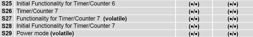
95 APPENDIX D 95
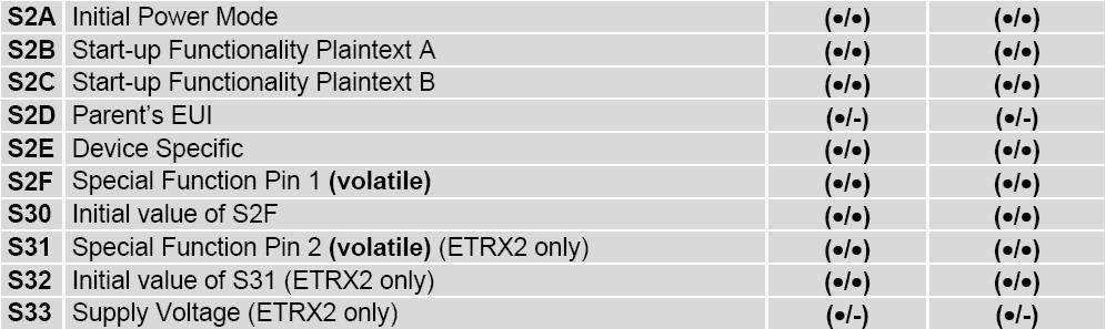
96 S-Registers 96
ZigBee/ David Sanchez Sanchez.
 ZigBee/802.15.4 David Sanchez Sanchez david.sanchezs@upf.edu Lecture Overview 1. Introduction and motivation to ZigBee 2. ZigBee/802.15.4 specification 1. Definitions 2. MAC communication modes 3. Network
ZIGBEE. Erkan Ünal CSE 401 SPECIAL TOPICS IN COMPUTER NETWORKS
 ZIGBEE Erkan Ünal CSE 401 SPECIAL TOPICS IN COMPUTER NETWORKS OUTLINE ZIGBEE AND APPLICATIONS IEEE 802.15.4 PROTOCOL ZIGBEE PROTOCOL ZIGBEE ALLIANCE ZIGBEE APPLICATIONS PHYSICAL LAYER MAC LAYER ZIGBEE
Wireless communication standards: What makes them unattractive for WSN:
 Wireless communication standards: IEEE 802.11 a/b/g Bluetooth GSM What makes them unattractive for WSN: Power hungry (need big batteries) Complexity (need lots of clock cycles and memory) New protocol
Introduction to IEEE
 Introduction to IEEE 802.15.4 Marcos Rubinstein IEEE 802.15.4 Short range, low bit rate, low power consumption Home Automotive Industrial applications Games Metering 1 PHY speeds 250 kbps 40 kbps 20 kbps.
Outline. TWR Module. Different Wireless Protocols. Section 7. Wireless Communication. Wireless Communication with
 Section 7. Wireless Communication Outline Wireless Communication with 802.15.4/Zigbee Protocol Introduction to Freescale MC12311 802.15.4/Zigbee Protocol TWR-12311 Module TWR-MC12311 Smart Radio Features
CHAPTER 4 CROSS LAYER INTERACTION
 38 CHAPTER 4 CROSS LAYER INTERACTION The cross layer interaction techniques used in the lower layers of the protocol stack, solve the hidden and exposed terminal problems of wireless and ad hoc networks.
WPAN/WBANs: ZigBee. Dmitri A. Moltchanov kurssit/elt-53306/
 WPAN/WBANs: ZigBee Dmitri A. Moltchanov E-mail: dmitri.moltchanov@tut.fi http://www.cs.tut.fi/ kurssit/elt-53306/ IEEE 802.15 WG breakdown; ZigBee Comparison with other technologies; PHY and MAC; Network
WIRELESS-NETWORK TECHNOLOGIES/PROTOCOLS
 3 WIRELESS-NETWORK TECHNOLOGIES/PROTOCOLS Dr. H. K. Verma Distinguished Professor (EEE) Sharda University, Greater Noida (Formerly: Deputy Director and Professor of Instrumentation Indian Institute of
Message acknowledgement and an optional beacon. Channel Access is via Carrier Sense Multiple Access with
 ZigBee IEEE 802.15.4 Emerging standard for low-power wireless monitoring and control Scale to many devices Long lifetime is important (contrast to Bluetooth) 10-75m range typical Designed for industrial
ZigBee and IEEE
 n overview of ZigBee and IEEE 80.5.4 IEEE Standard for Information technology Telecommunications and information exchange between systems Local and metropolitan area networks Specific requirements Part
Topics. Introduction Architecture Node Types Network Topologies Traffic Modes Frame Format Applications Conclusion
 ZigBee Topics Introduction Architecture Node Types Network Topologies Traffic Modes Frame Format Applications Conclusion Introduction The Wireless technologies (WiFi,GSM,and Bluetooth) All have one thing
Guide to Wireless Communications, 3 rd Edition. Objectives
 Guide to Wireless Communications, 3 rd Edition Chapter 5 Wireless Personal Area Networks Objectives Describe a wireless personal area network (WPAN) List the different WPAN standards and their applications
WIRELESS TECHNOLOGIES
 WIRELESS TECHNOLOGIES Bluetooth, ZigBee and ANT Thomas Aasebø OVERVIEW What are wireless sensor networks? What are personal area networks? What are these networks typically used for? Bluetooth, ZigBee
ZigBee & Wireless Sensor Networks Case Study: ZigBee & IEEE S.rou.2. ZigBee Solution. What is ZigBee?
 S.rou.2-2 Wireless Sensor Networks Case Study: ZigBee & IEEE802.15.4 S.rou.2 ZigBee & 802.15.4 ZigBee overview IEEE 802.15.4 overview ZigBee & bluetooth End Dr.M.Y.Wu@CSE Shanghai Jiaotong University Shanghai,
CHAPTER 3 BLUETOOTH AND IEEE
 CHAPTER 3 BLUETOOTH AND IEEE 802.15 These slides are made available to faculty in PowerPoint form. Slides can be freely added, modified, and deleted to suit student needs. They represent substantial work
Wireless Sensor Networks
 Wireless Sensor Networks 1 Ch. Steup / J. Kaiser, IVS-EOS Ubiquitous Sensing 2 Ch. Steup / J. Kaiser, IVS-EOS IEEE 802.x Wireless Communication 3 Ch. Steup / J. Kaiser, IVS-EOS Wireless Technology Comparision
By Ambuj Varshney & Akshat Logar
 By Ambuj Varshney & Akshat Logar Wireless operations permits services, such as long range communications, that are impossible or impractical to implement with the use of wires. The term is commonly used
WIRELESS SENSOR NETWORK
 1 WIRELESS SENSOR NETWORK Dr. H. K. Verma Distinguished Professor (EEE) Sharda University, Greater Noida (Formerly: Deputy Director and Professor of Instrumentation Indian Institute of Technology Roorkee)
Guide to Wireless Communications, Third Edition. Objectives
 Guide to Wireless Communications, Third Edition Chapter 7 Low-Speed Wireless Local Area Networks Objectives Describe how WLANs are used List the components and modes of a WLAN Describe how an RF WLAN works
Zigbee protocol stack overview
 Zigbee protocol stack overview 2018 ASSUMPTIONS FOR USING THIS TEACHING MATERIAL DSR and OTSL takes no responsibility about the problem which occurs as a result of applying the technical information written
Principles of Wireless Sensor Networks. Medium Access Control and IEEE
 http://www.ee.kth.se/~carlofi/teaching/pwsn-2011/wsn_course.shtml Lecture 7 Stockholm, November 8, 2011 Medium Access Control and IEEE 802.15.4 Royal Institute of Technology - KTH Stockholm, Sweden e-mail:
Principles of Wireless Sensor Networks
 Principles of Wireless Sensor Networks https://www.kth.se/social/course/el2745/ Lecture 5 January 31, 2013 Carlo Fischione Associate Professor of Sensor Networks e-mail: carlofi@kth.se http://www.ee.kth.se/~carlofi/
3. Evaluation of Selected Tree and Mesh based Routing Protocols
 33 3. Evaluation of Selected Tree and Mesh based Routing Protocols 3.1 Introduction Construction of best possible multicast trees and maintaining the group connections in sequence is challenging even in
Davide Quaglia Assistant CS depart University of Verona, Italy
 Emad Ebeid Ph.D. student @ CS depart University of Verona, Italy EmadSamuelMalki.Ebeid@univr.it Davide Quaglia Assistant Professor @ CS depart University of Verona, Italy Davide.Quaglia@univr.it 2 1 ZigBee
Communications Options for Wireless Sensor Networks. Marco Zennaro and Antoine Bagula ICTP and UWC Italy and South Africa
 Communications Options for Wireless Sensor Networks Marco Zennaro and Antoine Bagula ICTP and UWC Italy and South Africa WSN communications options When considering communications options, parameters to
CS263: Wireless Communications and Sensor Networks
 CS263: Wireless Communications and Sensor Networks Matt Welsh Lecture 6: Bluetooth and 802.15.4 October 12, 2004 2004 Matt Welsh Harvard University 1 Today's Lecture Bluetooth Standard for Personal Area
ZigBee. Jan Dohl Fabian Diehm Patrick Grosa. Dresden,
 Faculty of Computer Science Chair of Computer Networks, Wireless Sensor Networks, Dr. W. Dargie ZigBee Jan Dohl Fabian Diehm Patrick Grosa Dresden, 14.11.2006 Structure Introduction Concepts Architecture
EL2745 Principles of Wireless Sensor Networks
 EL2745 Principles of Wireless Sensor Networks www.kth.se/student/program-kurser/kurshemsidor/kurshemsidor/control/el2745 Lecture 5 Stockholm, February 2, 2012 Carlo Fischione Royal Institute of Technology
Chapter 7. ZigBee (IEEE ) Liang Zhao, Andreas Timm-Giel
 Liang Zhao, Andreas Timm-Giel") Chapter 7 ZigBee (IEEE 802.15.4) Liang Zhao, Andreas Timm-Giel Outline 7.1 Introduction and Overview of IEEE 802.15.4 / ZigBee 7.2 IEEE 802.15.4: Physical Layer Protocols 7.3 IEEE 802.15.4: MAC Layer Protocols
Chapter 7 ZigBee (IEEE 802.15.4) Liang Zhao, Andreas Timm-Giel Outline 7.1 Introduction and Overview of IEEE 802.15.4 / ZigBee 7.2 IEEE 802.15.4: Physical Layer Protocols 7.3 IEEE 802.15.4: MAC Layer Protocols
Wireless# Guide to Wireless Communications. Objectives
 Wireless# Guide to Wireless Communications Chapter 7 Low-Speed Wireless Local Area Networks Objectives Describe how WLANs are used List the components and modes of a WLAN Describe how an RF WLAN works
ISSN (PRINT): , (ONLINE): , VOLUME-6, ISSUE-1,
: , (ONLINE): , VOLUME-6, ISSUE-1,") DESIGN OF MULTIMODE GATEWAY FOR DATA ACQUISITION TO HIGH END DATA MONITORING USING IEEE802.15.4 Madhhav G.Raut 1 & Pradip B.Dahikar 2 Hislop College,Civil Lines, Nagpur & Kamala Nehru Mahavidyalaya,Nagpur,India
DESIGN OF MULTIMODE GATEWAY FOR DATA ACQUISITION TO HIGH END DATA MONITORING USING IEEE802.15.4 Madhhav G.Raut 1 & Pradip B.Dahikar 2 Hislop College,Civil Lines, Nagpur & Kamala Nehru Mahavidyalaya,Nagpur,India
ENSC 427: COMMUNICATION NETWORKS
 ENSC 427: COMMUNICATION NETWORKS Simulation of ZigBee Wireless Sensor Networks Final Report Spring 2012 Mehran Ferdowsi Mfa6@sfu.ca Table of Contents 1. Introduction...2 2. Project Scope...2 3. ZigBee
Wireless LANs. The Protocol Stack The Physical Layer The MAC Sublayer Protocol The Frame Structure Services 802.
 Wireless LANs The 802.11 Protocol Stack The 802.11 Physical Layer The 802.11 MAC Sublayer Protocol The 802.11 Frame Structure Services 56 802.11 The 802.11 Working Group The IEEE 802.11 was formed in July
Wireless Sensor Networks
 Wireless Sensor Networks c.buratti@unibo.it +39 051 20 93147 Office Hours: Tuesday 3 5 pm @ Main Building, third floor Credits: 6 Standard Solutions Data-rate RFID 20 cm, 10-200 kbps 100m, 11-100 Mbps
AT THE END OF THIS SECTION, YOU SHOULD HAVE AN UNDERSTANDING OF THE
 Wireless Technology AT THE END OF THIS SECTION, YOU SHOULD HAVE AN UNDERSTANDING OF THE UNDERLYING WIRELESS TECHNOLOGIES. References 2 The physical layer provides mechanical, electrical, l functional,
Modulation. Propagation. Typical frequency bands
 References Wireless Technology 2 AT THE END OF THIS SECTION, YOU SHOULD HAVE AN UNDERSTANDING OF THE UNDERLYING WIRELESS TECHNOLOGIES. The physical layer provides mechanical, electrical, l functional,
Chapter 3.1 Acknowledgment:
 Chapter 3.1 Acknowledgment: This material is based on the slides formatted by Dr Sunilkumar S. manvi and Dr Mahabaleshwar S. Kakkasageri, the authors of the textbook: Wireless and Mobile Networks, concepts
Sensor Application for Museum Guidance
 Sensor Application for Museum Guidance Radka Dimitrova a a TU,Dresden, Germany, e-mail: dimitrova@ifn.et.tu-dresden.de Abstract - This article examines the conditions for successful communication and power
Wireless Personal Area Networks & Wide Area Networks
 Wireless Personal Area Networks & Wide Area Networks Patrick J. Stockreisser p.j.stockreisser@cs.cardiff.ac.uk Lecture Outline In the lecture we will: Look at PAN s in more detail Look at example networks
Chapter 7. IEEE ZigBee. Liang Zhao, Andreas Timm-Giel
 Chapter 7 IEEE 802.15.4 ZigBee Liang Zhao, Andreas Timm-Giel Outline 7.1 Introduction and Overview of IEEE 802.15.4 / ZigBee 7.2 IEEE 802.15.4: Physical Layer Protocols 7.3 IEEE 802.15.4: MAC Layer Protocols
VISHVESHWARAIAH TECHNOLOGICAL UNIVERSITY BELGAUM-10 S.D.M COLLEGE OF ENGINEERING AND TECHNOLOGY DHARWAD-02
 VISHVESHWARAIAH TECHNOLOGICAL UNIVERSITY BELGAUM-10 S.D.M COLLEGE OF ENGINEERING AND TECHNOLOGY DHARWAD-02 A seminar report on ZIGBEE WIRELESS SYSTEM Submitted by MAHANTESH.B.BIKKANNAVAR 2SD05CS033 8 th
Wireless and WiFi. Daniel Zappala. CS 460 Computer Networking Brigham Young University
 Wireless and WiFi Daniel Zappala CS 460 Computer Networking Brigham Young University Wireless Networks 2/28 mobile phone subscribers now outnumber wired phone subscribers similar trend likely with Internet
Introduction to Wireless Networking ECE 401WN Spring 2009
 I. Overview of Bluetooth Introduction to Wireless Networking ECE 401WN Spring 2009 Lecture 6: Bluetooth and IEEE 802.15 Chapter 15 Bluetooth and IEEE 802.15 What is Bluetooth? An always-on, short-range
standards like IEEE [37], IEEE [38] or IEEE [39] do not consider
![standards like IEEE [37], IEEE [38] or IEEE [39] do not consider](/thumbs/93/112368156.jpg "standards like IEEE [37], IEEE [38] or IEEE [39] do not consider") Chapter 5 IEEE 802.15.4 5.1 Introduction Wireless Sensor Network(WSN) is resource constrained network developed specially targeting applications having unattended network for long time. Such a network
Chapter 5 IEEE 802.15.4 5.1 Introduction Wireless Sensor Network(WSN) is resource constrained network developed specially targeting applications having unattended network for long time. Such a network
Seminar: Mobile Systems. Krzysztof Dabkowski Supervisor: Fabio Hecht
 Personal Area Networks Seminar: Mobile Systems November 19th 2009 Krzysztof Dabkowski Supervisor: Fabio Hecht Agenda Motivation Application areas Historical and technical overview Security issues Discussion
Mobile Communications
 Mobile Communications Wireless Personal Area Networks Manuel P. Ricardo Faculdade de Engenharia da Universidade do Porto 1 IEEE Standards 2 IEEE 802.15.4 Wireless PAN (Sensor Networks) 3 Information Current
Wireless Networks. CSE 3461: Introduction to Computer Networking Reading: , Kurose and Ross
 Wireless Networks CSE 3461: Introduction to Computer Networking Reading: 6.1 6.3, Kurose and Ross 1 Wireless Networks Background: Number of wireless (mobile) phone subscribers now exceeds number of wired
Chapter 6 Wireless and Mobile Networks
 Chapter 6 Wireless and Mobile Networks Computer Networking: A Top Down Approach Featuring the Internet, 3 rd edition. Jim Kurose, Keith Ross Addison-Wesley, July 2004. 6: Wireless and Mobile Networks 6
Communication In Smart Grid -Part3
 Communication In Smart Grid -Part3 Dr.-Ing. Abdalkarim Awad 09.12.2015 Informatik 7 Rechnernetze und Kommunikationssysteme Zigbee General characteristics Data rates of 250 kbps, 20 kbps and 40kpbs. Star
Temporary Interconnection of ZigBee Personal Area Network (PAN)
") Temporary Interconnection of Personal Area Network (PAN) Sewook Jung, Alexander Chang, and Mario Gerla Department of Computer Science University of California, Los Angeles {sewookj,acmchang,gerla}@cs.ucla.edu
Temporary Interconnection of Personal Area Network (PAN) Sewook Jung, Alexander Chang, and Mario Gerla Department of Computer Science University of California, Los Angeles {sewookj,acmchang,gerla}@cs.ucla.edu
Wireless control that simply works CES January 9, Bob Heile Chairman, Zigbee Alliance
 Wireless control that simply works CES 2004 January 9, 2004 Bob Heile Chairman, Zigbee Alliance 2 What is the ZigBee Alliance? A rapidly growing, worldwide, non-profit industry consortium consisting of
CSC 4900 Computer Networks: Wireless Networks
 CSC 4900 Computer Networks: Wireless Networks Professor Henry Carter Fall 2017 Last Time Mobile applications are taking off! What about current platforms is fueling this? How are an application s permission
LTE : The Future of Mobile Broadband Technology
 LTE : The Future of Mobile Broadband Technology Erick Setiawan tukangbajaksawah@gmail.com 1 Become a necessity today, where the wireless broadband technology needed to meet increasing expectations in terms
Computer Networks. Wireless LANs
 Computer Networks Wireless LANs Mobile Communication Technology according to IEEE (examples) Local wireless networks WLAN 802.11 Personal wireless nw WPAN 802.15 WiFi 802.11a 802.11b 802.11h 802.11i/e/
Advanced Mobile Computing and Networking - CS 560. Wireless Technologies. Bluetooth. Bluetooth. Bluetooth. Bluetooth 7/3/2014.
 Advanced Mobile Computing and Networking - CS 560 Assessment CA 40% - Assignment 20% - 2 Tests 10% each Exam 60% Wireless Technologies, Infrared Data Association (),, and Institute of Electrical and Electronic
Junseok Kim Wireless Networking Lab (WINLAB) Konkuk University, South Korea
 Konkuk University, South Korea") Junseok Kim Wireless Networking Lab (WINLAB) Konkuk University, South Korea http://usn.konkuk.ac.kr/~jskim 1 IEEE 802.x Standards 802.11 for Wireless Local Area Network 802.11 legacy clarified 802.11 legacy
Junseok Kim Wireless Networking Lab (WINLAB) Konkuk University, South Korea http://usn.konkuk.ac.kr/~jskim 1 IEEE 802.x Standards 802.11 for Wireless Local Area Network 802.11 legacy clarified 802.11 legacy
Controlling electrical home appliances, using Bluetooth Smart Technology (October 2015) Pedro José Vieira da Silva
 Pedro José Vieira da Silva") 1 Controlling electrical home appliances, using Smart Technology (October 2015) Pedro José Vieira da Silva Abstract This report presents and describes a Home Energy Management system that accomplish Home
1 Controlling electrical home appliances, using Smart Technology (October 2015) Pedro José Vieira da Silva Abstract This report presents and describes a Home Energy Management system that accomplish Home
Wireless# Guide to Wireless Communications. Objectives
 Wireless# Guide to Wireless Communications Chapter 6 High Rate Wireless Personal Area Networks Objectives Define a high rate wireless personal area network (HR WPAN) List the different HR WPAN standards
WZRDnet. A Low-Power Wireless Ad-Hoc Mesh Network for Austere Tactical Environments. February 14, 2018
 White Paper TELEGRID Technologies, Inc. WZRDnet A Low-Power Wireless Ad-Hoc Mesh Network for Austere Tactical Environments February 14, 2018 23 Vreeland Road Suite 290 Florham Park, NJ 07932 www.telegrid.com
Ah-Hoc, PAN, WSN,... Introduction Bluetooth ( ) Zigbee ( ) Renato Lo Cigno
 Zigbee ( ) Renato Lo Cigno") Ah-Hoc, PAN, WSN,... Introduction Bluetooth (802.15.1) Zigbee (802.15.4) Renato Lo Cigno www.dit.unitn.it/locigno/ Ad-Hoc Networks Built by the userse themselves to support specific (in time, space, applications)
Ah-Hoc, PAN, WSN,... Introduction Bluetooth (802.15.1) Zigbee (802.15.4) Renato Lo Cigno www.dit.unitn.it/locigno/ Ad-Hoc Networks Built by the userse themselves to support specific (in time, space, applications)
Wireless and Mobile Networks 7-2
 Wireless and Mobile Networks EECS3214 2018-03-26 7-1 Ch. 6: Wireless and Mobile Networks Background: # wireless (mobile) phone subscribers now exceeds # wired phone subscribers (5-to-1)! # wireless Internet-connected
Wireless Networked Systems
 Wireless Networked Systems CS 795/895 - Spring 2013 Lec #7: Medium Access Control WPAN, Bluetooth, ZigBee Tamer Nadeem Dept. of Computer Science Bluetooth Page 2 Spring 2013 CS 795/895 - Wireless Networked
1. IEEE and ZigBee working model.
 ZigBee SoCs provide cost-effective solutions Integrating a radio transceiver, data processing unit, memory and user-application features on one chip combines high performance with low cost Khanh Tuan Le,
Wireless Local Area Networks (WLANs)) and Wireless Sensor Networks (WSNs) Computer Networks: Wireless Networks 1
) and Wireless Sensor Networks (WSNs) Computer Networks: Wireless Networks 1") Wireless Local Area Networks (WLANs)) and Wireless Sensor Networks (WSNs) Computer Networks: Wireless Networks 1 Wireless Local Area Networks The proliferation of laptop computers and other mobile devices
Wireless Local Area Networks (WLANs)) and Wireless Sensor Networks (WSNs) Computer Networks: Wireless Networks 1 Wireless Local Area Networks The proliferation of laptop computers and other mobile devices
04/11/2011. Wireless LANs. CSE 3213 Fall November Overview
 Wireless LANs CSE 3213 Fall 2011 4 November 2011 Overview 2 1 Infrastructure Wireless LAN 3 Applications of Wireless LANs Key application areas: LAN extension cross-building interconnect nomadic access
Wireless Local Area Networks (WLANs) and Wireless Sensor Networks (WSNs) Primer. Computer Networks: Wireless LANs
 and Wireless Sensor Networks (WSNs) Primer. Computer Networks: Wireless LANs") Wireless Local Area Networks (WLANs) and Wireless Sensor Networks (WSNs) Primer 1 Wireless Local Area Networks (WLANs) The proliferation of laptop computers and other mobile devices (PDAs and cell phones)
Wireless Local Area Networks (WLANs) and Wireless Sensor Networks (WSNs) Primer 1 Wireless Local Area Networks (WLANs) The proliferation of laptop computers and other mobile devices (PDAs and cell phones)
Fuzzy Duty Cycle Adaption Algorithm for IEEE Star Topology Networks
 Computer Systems Department, Technical Institute / Qurna, Basra, Iraq email: hayderaam@gmail.com Received: 4/1 /212 Accepted: 22/7 /213 Abstract IEEE 82.15.4 is a standard designed for low data rate, low
Wireless (NFC, RFID, Bluetooth LE, ZigBee IP, RF) protocols for the Physical- Data Link layer communication technologies
 protocols for the Physical- Data Link layer communication technologies") Wireless (NFC, RFID, Bluetooth LE, ZigBee IP, RF) protocols for the Physical- Data Link layer communication technologies 1 Connected devices communication to the Local Network and Gateway 1 st to i th
Wireless (NFC, RFID, Bluetooth LE, ZigBee IP, RF) protocols for the Physical- Data Link layer communication technologies 1 Connected devices communication to the Local Network and Gateway 1 st to i th
Data Communications. Data Link Layer Protocols Wireless LANs
 Data Communications Data Link Layer Protocols Wireless LANs Wireless Networks Several different types of communications networks are using unguided media. These networks are generally referred to as wireless
Wireless Sensor Networks
 Wireless Sensor Networks c.buratti@unibo.it +39 051 20 93147 Office Hours: Tuesday 3 5 pm @ Main Building, third floor Credits: 6 Standard Solutions for Wireless Networks 2 Standard Solutions for WSN 3
Victor Kwong Marketing Manager
 Nov, 2008 Introduction to Freescale's Synkro Platform: Wireless Control and Automation for Next-Generation Home Entertainment Products PC106 Victor Kwong Marketing Manager of Freescale Semiconductor, Inc.
A Comprehensive Study of ZigBee. Presented by Dr. K F Tsang Citycom Technology Ltd. Tel:
 A Comprehensive Study of ZigBee Presented by Dr. K F Tsang Citycom Technology Ltd. Tel: 2788-7806 Email: ee330015@cityu.edu.hk 1 1 Outline Introduction of ZigBee Market analysis Characteristics of ZigBee
ZigBee Technology: Wireless Control that Simply Works
 ZigBee Technology: Wireless Control that Simply Works Patrick Kinney Kinney Consulting LLC Chair of IEEE 802.15.4 Task Group Secretary of ZigBee BoD Chair of ZigBee Building Automation Profile WG - 1 -
6.9 Summary. 11/20/2013 Wireless and Mobile Networks (SSL) 6-1. Characteristics of selected wireless link standards a, g point-to-point
 6-1. Characteristics of selected wireless link standards a, g point-to-point") Chapter 6 outline 6.1 Introduction Wireless 6.2 Wireless links, characteristics CDMA 6.3 IEEE 802.11 wireless LANs ( wi-fi ) 6.4 Cellular Internet Access architecture standards (e.g., GSM) Mobility 6.5
Chapter 6 outline 6.1 Introduction Wireless 6.2 Wireless links, characteristics CDMA 6.3 IEEE 802.11 wireless LANs ( wi-fi ) 6.4 Cellular Internet Access architecture standards (e.g., GSM) Mobility 6.5
Wireless Best Kept Secret For Now
 Wireless Best Kept Secret For Now IoT Event June 2014 Gilles Thonet Managing Director Europe, ZigBee Alliance 2014 ZigBee Alliance. All rights reserved. 1 ZigBee Alliance at 10 Years Who we are Open, global,
RESOURCES. By: Chris Downey, Laird Technologies Product Manager, Telematics & Wireless M2M Date: May 25, 2011
 Moving Beyond Zigbee for Star Networks RESOURCES By: Chris Downey, Laird Technologies Product Manager, Telematics & Wireless M2M Date: May 25, 2011 Multi-hop mesh protocols, such as Zigbee, are getting
WNC-0300USB. 11g Wireless USB Adapter USER MANUAL
 WNC-0300USB 11g Wireless USB Adapter USER MANUAL Contents 1. Introduction...3 1.1 Product Feature...3 1.2 System Requirement...3 2. Getting Start...3 2.1 LED Indicators...3 2.2 Install the 54Mbps Wireless
e-pg Pathshala Quadrant 1 e-text
 e-pg Pathshala Subject : Computer Science Module: Bluetooth Paper: Computer Networks Module No: CS/CN/37 Quadrant 1 e-text In our journey on networks, we are now exploring wireless networks. We looked
A smart Home Security system based on ARM9
 A smart Home Security system based on ARM9 B. Srinivasa sarma, Dr. P. Sudhakar Reddy, IEEE member Department of Electronics and communications engineering, Sri Kalahastheeswara Institute of Technology,
IEEE Testing Signal Compliance of ZigBee Standard
 IEEE802.15.4 Testing Signal Compliance of ZigBee Standard Tektronix 1 Agenda: 1: What is ZigBee 2: ZigBee Specification 3: ZigBee Signal Analysis 4: Demonstration for ZigBee analysis 2 What is ZigBee (1)
Data Communication. Introduction of Communication. Data Communication. Elements of Data Communication (Communication Model)
") Data Communication Introduction of Communication The need to communicate is part of man s inherent being. Since the beginning of time the human race has communicated using different techniques and methods.
Data Communication Introduction of Communication The need to communicate is part of man s inherent being. Since the beginning of time the human race has communicated using different techniques and methods.
Mohammad Hossein Manshaei 1393
 Mohammad Hossein Manshaei manshaei@gmail.com 1393 Wireless Links, WiFi, Cellular Internet Access, and Mobility Slides derived from those available on the Web site of the book Computer Networking, by Kurose
Data Communication & Networks G Session 5 - Main Theme Wireless Networks. Dr. Jean-Claude Franchitti
 Data Communication & Networks G22.2262-001 Session 5 - Main Theme Wireless Networks Dr. Jean-Claude Franchitti New York University Computer Science Department Courant Institute of Mathematical Sciences
Emad Ebeid Ph.D. CS depart University of Verona, Italy
 Emad Ebeid Ph.D. student @ CS depart University of Verona, Italy EmadSamuelMalki.Ebeid@univr.it Davide Quaglia Assistant Professor @ CS depart University of Verona, Italy Davide.Quaglia@univr.it 2 1 ZigBee
Case study of Wireless Technologies in Industrial Applications
 International Journal of Scientific and Research Publications, Volume 7, Issue 1, January 2017 257 Case study of Wireless Technologies in Industrial Applications Rahul Hanumanth Rao Computer Information
Interface The exit interface a packet will take when destined for a specific network.
 The Network Layer The Network layer (also called layer 3) manages device addressing, tracks the location of devices on the network, and determines the best way to move data, which means that the Network
Topic 02: IEEE
 Topic 02: IEEE 802.15.4 Tuesday 20 Feb 2007 ICTP-ITU School on Wireless Networking for Scientific Applications in Developing Countries Bhaskaran Raman Department of CSE, IIT Kanpur http://www.cse.iitk.ac.in/users/braman/
Standard for wireless sensor networks. Developed and promoted by the ZigBee alliance
 Stefano Chessa Zigbee Standard for wireless sensor networks Developed and promoted by the ZigBee alliance Applications: Home automation (domotics, ambient assisted living,...) Health care Consumer electronics
Topic 2b Wireless MAC. Chapter 7. Wireless and Mobile Networks. Computer Networking: A Top Down Approach
 Topic 2b Wireless MAC Chapter 7 Wireless and Mobile Networks Computer Networking: A Top Down Approach 7 th edition Jim Kurose, Keith Ross Pearson/Addison Wesley April 2016 7-1 Ch. 7: Background: # wireless
Wireless Personal Area Networks (WPANs) Wireless PAN
 Wireless PAN") Wireless Personal Area Networks (WPANs) IEEE P802.15 Working Group Wireless PAN Applications Home Networking Automotive Networks Industrial Networks Interactive Toys Remote Metering Overview Data rates
Wireless Personal Area Networks (WPANs) IEEE P802.15 Working Group Wireless PAN Applications Home Networking Automotive Networks Industrial Networks Interactive Toys Remote Metering Overview Data rates
Development of Gas Smart Metering System
 International Gas Union Research Conference 2014 Development of Gas Smart Metering System Kentaro Suzawa, Jun Fujiwara Tokyo Gas Co., Ltd. Masahiro Yasui, Yasuhiro Fujii, Akiharu Asada, Ryo Yamashita Yudai
KW41Z IEEE and BLE Coexistence Performance
 NXP Semiconductors Document Number: AN12231 Application Note Rev. 0, 08/2018 KW41Z IEEE 802.15.4 and BLE Coexistence Performance MWS module 1. About this manual This document aims to evaluate the performance
ZigBee----free as a bee!
 ZigBee----free as a bee! ZigBee is the perfect wireless solution for industrial control, medical purposes, alarm systems, building automation, and so many others. You just name it! ICP DAS releases the
A New Application of Zigbee Based Wireless Automation System for Safety of Municipal Workers
 A New Application of Zigbee Based Wireless Automation System for Safety of Municipal Workers Mr. Balaji. v. phad 1, Dr. H. K. Naidu 2, Prof. Pratik Gutke 3 1,2,3 Integrated Power System Dept., Tulsiramji
Overview of Wi-Fi. Dr. Srikanth Subramanian CKO, Nanocell Networks Wi-Fi A Wireless Success Story
 Overview of Wi-Fi Dr. Srikanth Subramanian CKO, Nanocell Networks www.nanocellnetworks.com Wi-Fi A Wireless Success Story Wi-Fi present in all laptops/aps Wi-Fi Traffic trends Source: Cisco percentage
CSC344 Wireless and Mobile Computing. Department of Computer Science COMSATS Institute of Information Technology
 CSC344 Wireless and Mobile Computing Department of Computer Science COMSATS Institute of Information Technology Wireless Sensor Networks A wireless sensor network (WSN) is a wireless network consisting
Low-Rate Wireless Personal Area Networks IEEE Fernando Solano Warsaw University of Technology
 Low-Rate Wireless Personal Area Networks IEEE 802.15.4 Fernando Solano Warsaw University of Technology fs@tele.pw.edu.pl Wireless Sensor Networks and Hardware A bad example Remote bulb control Reduce Energy
II. ZigBee technology. III. ZigBee technology as the basis of wireless AMR system
 II. ZigBee technology ZigBee technology is a low data rate, low power consumption, low cost, wireless networking protocol targeted towards automation and remote control applications [3]. It operates on
ZigBee: The New Frontier for Energy Efficiency
 ZigBee: The New Frontier for Energy Efficiency Brent Hodges VP Marketing and Business Development ZigBee Alliance April 2008 Copyright 2008 All Rights Reserved. Metering, Billing/CIS America 2008, San
Learning Objectives. Introduction. Advantages of WLAN. Information Technology. Mobile Computing. Module: Wireless Local Area Network: IEEE 802.
 Information Technology Mobile Computing Module: Wireless Local Area Network: IEEE 802.11 Learning Objectives Introduction to Wireless Local Area Network Advantages of WLAN Types of WLAN IEEE 802.11 standards