SD-Access Wireless Design and Deployment Guide
|
|
|
- Miles Knight
- 5 years ago
- Views:
Transcription

1 SD-Access Wireless Design and Deployment Guide Executive Summary 2 Software Defined Access 2 SD Access Wireless 3 SD Access Wireless Architecture 4 Setting up SD-Access Wireless with DNAC 13 SD Access Design 20 SD Access Policy 30 SD-Access Overlay Provisioning 35 SD Access Wireless A Look under the Hood 57 Designing the Wireless integration in SD-Access 61 SD-Access Wireless Guest Access Design 69 Multicast in SD-Access Wireless 71 High Availability in SD-Access Wireless 74 Appendix: SD-Access Wireless Features deep dive 77

2 Revised: May 26, 2018 Executive Summary Digitization is transforming business in every industry - requiring every company to be an IT company. Studies show, companies that master digital will not only drive more revenue, but will be 29% more profitable on average [Source: Leading Digital]. This is critical and urgent, as 40% of incumbents are at risk of being displaced [Source: Digital Vortex] Cisco DNA is an open, software-driven architecture built on a set of design principles with the objective of providing: Insights and Actions to drive faster business innovation Automaton and Assurance to lower it costs and complexity while meeting business and user expectations Security and Compliance to reduce risk as the organization continues to expand and grow Software Defined Access is a critical building block of the DNA architecture and bring the DNA principles and advantages to Cisco customers. Software Defined Access Software Defined Access (SD-Access) is Cisco's next generation Enterprise Networking access solution, designed to offer integrated security, segmentation, and elastic service roll-outs via a Fabric based infrastructure and an outstanding GUI experience for automated network provisioning via the new DNA Center application. By automating day-to-day tasks such as configuration, provisioning and troubleshooting, SD-Access reduces the time it takes to adapt the network, improves issue resolutions and reduces security breach impacts. This results in a significant CapEx and OpEx savings for the business. The benefits of SDA are summarized in the picture below: In this document the focus is on the wireless integration in SD-Access; it is assumed that the reader is familiar with the concept of SD-Access Fabric and the main components of this network architecture; for additional information on SD-Access capabilities please refer to the SD-Access site and SD-Access Design Guide (CVD). 2
 deployments will be leveraged in")
3 SD Access Wireless SD-Access Wireless is defined as the integration of wireless access in the SD-Access architecture in order to gain all the advantages of Fabric and DNAC automation. Some of these benefits are: Centralized Wireless control plane : the same innovative RF features that Cisco has today in Cisco Unified Wireless Network (CUWN) deployments will be leveraged in SD-Access Wireless as well. Wireless operations stay the same as with CUWN in terms of RRM, client onboarding and client mobility and so on which simplifies IT adoption Optimized Distributed Data Plane : the data plane is distributed at the edge switches for optimal performance and scalability without the hassles usually associated with distributing traffic (spanning VLANs, subnetting, large broadcast domains, etc.) Seamless L2 Roaming everywhere : SD-Access Fabric allows clients to roam seamlessly across the campus while retaining the same IP address Simplified Guest and mobility tunneling : an anchor WLC controller is not needed any more and the guest traffic can directly go to the DMZ without hopping through a Foreign controller Policy simplification: SD Access breaks the dependencies between Policy and network constructs (IP address and VLANs) simplifying the way we can define and implement Policies. For both wired and wireless clients Segmentation made easy : Segmentation is carried end to end in the Fabric and is hierarchical, based on Virtual Networks (VNIs) and Scalable Group Tags(SGTs). Same segmentation policy is applied to both wired and wireless users All these advantages while still maintaining: Best in Class Wireless with Future-proof Wave2 APs and 3504/5520/8540 WLCs Investment protection by supporting existing AireOS WLC; SD-Access Wireless is optimized for acWave2 APs but also supports Wave 1 APs The benefits are summarized in the picture below: Wireless integration in SD-Access If customer has a wired network based on SD-Access Fabric, there are two options to integrate the wireless access: 3

4 1. SD-Access Wireless Architecture 2. CUWN Wireless Over the Top (OTT) Let's first examine the SD-Access Wireless since it brings the full advantages of Fabric for wireless users and things. Initially the architecture and the main components are introduced and then the reader will learn how to setup a SD-Access Wireless network using DNAC. OTT is basically running tradition wireless on top of a Fabric wired network. This option will be covered later in the document together with the Design considerations. SD Access Wireless Architecture The overall architecture is represented in the diagram below: Figure 1: SD-Access Wireless In SD-Access Wireless, the Control plane is centralized: this means that, as with CUWN, a CAPWAP tunnel is maintained between APs and WLC. the main difference is that, the data plane is distributed using VXLAN directly from the Fabric enabled APs. WLC and APs are integrated into the Fabric and the Access Points connect to the Fabric overlay (Endpoint ID space) network as special clients. SD-Access Wireless Architecture Components Below is the main architecture diagram with a description of the main components. 4

5 Figure 2: SD-Access Wireless Architecture Control Plane Nodes Host database that manages Endpoint ID to Device relationships Fabric Border Nodes A Fabric device (e.g. Core or Distribution switch) that connects external L3 network(s) to the SDA Fabric. There are two type of Border nodes: Fabric Border to connect to known routes and Default Border to connect to unknown routes. In the rest of the document the Border nomenclature is used when we refer to the generic function of connecting Fabric to the outside network Fabric Edge Nodes A Fabric device (e.g. Access switch) that connects Wired Endpoints to the SDA Fabric Fabric Wireless Controller Wireless Controller (WLC) that is fabric-enabled Fabric Mode APs Access Points that are fabric-enabled DNA Center (DNAC) Single pane of glass for Enterprise network Automation and Assurance. DNAC brings together the Enterprise SDN Controller, the Policy Engine (ISE) and the Analytics Engine (NDP) Policy Engine External ID Services (e.g. ISE) is leveraged for dynamic User or Device to Group mapping and policy definition Analytics Engine External Data Collector (Cisco Network Data Platform) is leveraged to analyze User or Device to App flows and monitor fabric status The following sections describe the roles and functions of the main components of the SD-Access Wireless Architecture Control Plane Node Fabric Control-Plane Node is based on a LISP Map Server / Resolver and runs the Fabric Endpoint ID Database to provide overlay reachability information. 5


6 CP is the Host Data Base, tracks Endpoint ID (EID) to Edge Node bindings, along with other attributes CP supports multiple types of Endpoint ID lookup keys (IPv4 /32, IPv6 /128 (*) or MAC addresses) It receives prefix registrations from Edge Nodes and Fabric WLCs for wired local endpoints and wireless clients respectively It resolves lookup requests from remote Edge Nodes to locate Endpoints It updates Fabric Edge nodes and Border nodes with wireless client mobility and RLOC information (*) IPv6 is not supported in the first release of SDA Fabric Edge Node Fabric edge provides connectivity for Users and Devices connected to the Fabric. Responsible for Identifying and Authenticating Wired Endpoints Register wirelessipv4/ipv6 Endpoint ID information with the Control-Plane Node(s) Provides AnycastL3 Gateway for connected Endpoints Provide VN services for Wireless Clients Onboard APs into fabric and form VXLAN tunnels with APs Provides Guest functionality for wireless hosts interacting with the Guest Border, and Guest Control Plane node Fabric Border Node All traffic entering or leaving the Fabric goes through the Fabric Border. 6


7 There are 2 types of Fabric Border node: Border and Default Border. Both types provide the fundamental routing entry and exit point for all data traffic going into and/or out of the Fabric Overlay, as well as for VN and/or group-based policy enforcement (for traffic outside the Fabric). A Fabric Border is used to add " known " IP/mask routes to the map system. A known route is any IP/mask that you want to advertise to your Fabric Edge nodes (e.g. Remote WLC, Shared Services, DC, Branch, Private Cloud, and so on) A Default Border is used for any " unknown " routes (e.g. Internet or Public Cloud),as a gateway of last resort A Border is where Fabric and non-fabric domains exchange Endpoint reachability and policy information Border is responsible for translation of context (VRF and SGT) from one domain to another Fabric Enabled WLC Fabric Enabled WLC integrates with the LISP Control Plane Control Plane is centralized at the WLC for Wireless functions. WLC is still responsible for AP image/config, Radio Resource Management (RRM) and client session management and roaming and all the other wireless Control Plane functions For Fabric integration: For wireless, client MAC address is used as EID Interacts with the Host Tracking DB on Control-Plane node for Client MAC address registration with SGT and Virtual Network Information The VN information is mapped to a VLAN on the FEs The WLC is responsible for updating the Host Tracking DB with roaming information for wireless clients 7

8 Fabric enabled WLC needs to be physically located on the same site as APs (initial release doesn't support APs to be deployed across a WAN from WLC) Note WLC and APs need to be within 20ms of latency, usually this mean same physical site. Fabric AP Fabric AP extends the SD-Access data plane to the wireless edge. Fabric AP is a local mode AP and needs to be directly connected to Fabric Edge switch CAPWAP control plane goes to the WLC using Fabric as transport Fabric is enabled per SSID : For Fabric enabled SSID, AP converts traffic to and encapsulates it into VXLAN encoding the VNI and SGT info of the client AP forwards client traffic based on forwarding table as programmed by the WLC. Usually VXLAN tunnel destination is first hop switch SGT and VRF based policies for wireless users on Fabric SSIDs are applied at the Fabric edge. Same as for wired For Fabric enabled SSIDs the user data plane is distributed at the APs leveraging VXLAN as encapsulation AP applies all wireless specific features like SSID policies, AVC, QoS, etc. Note For feature support on APs please refer to the WLC release notes. APs can be optionally connected to one of the supported Fabric Extended nodes. Please refer to the ordering guide for supported switch models 8

9 SD Access Wireless Protocols and Communication Interfaces Below a graphical and detailed explanation of the protocols and interfaces used in SD-Access Wireless Figure 3: Communication between different components WLC < > AP: Control plane WLC and AP communication is via CAPWAP similar to existing modes AP < > Switch: Data Traffic is switched from the AP to the Edge switch using VXLAN Tunnel encapsulation, UDP port is 4789 as per standard WLC < > Control Plane node: The wireless LAN controller communicates with the Control Plane (CP) running on TCP port 4342 on the controller DNAC < > WLC: In the first release DNAC uses the CLI interface through SSH/Telnet to configure the WLC Switch < > Control Plane node: The fabric enabled switches communicate with the Control Plane node on TCP port 4789 SD-Access Wireless Platform Support The SD-Access Wireless Architecture is supported on the following Wireless LAN controllers with AireOS release 8.5 and higher: AIR-CT3504 AIR-CT5520 9
.")
10 AIR-CT8540 This architecture is optimized for Wave2 11ac access points in Local mode: AP1810, AP1815, AP1830, AP1850, AP2800 and AP3800 Figure 4: Wave2 11ac Access Point support Wave ac access points are supported with SD-Access wireless with a limited set of features compared to Wave2 (please refer to the Release notes for more information). Outdoor APs are not supported in SDA 1.1 (November release). Support for these access points is in the roadmap. SD Access Wireless Network deployment Some important consideration to deploy WLC and APs in SD-Access Wireless network, please refer to the picture below: For Access Points: AP is directly connected to FE (or to an extended node switch) AP is part of Fabric overlay AP belongs to the INFRA_VN which is mapped to the global routing table AP joins the WLC in Local mode For the Wireless LAN Controller (WLC) WLC is connected outside Fabric (optionally directly to Border) WLC needs to reside in global routing table No need for inter-vrf leaking for AP to join the WLC WLC can only communicate to one Control Plane node (two for redundancy), hence one WLC can only belong to one Fabric Domain (FD) Note In order to make the Fabric control plane protocol more resilient, it's important that a specific route to the WLC is present in each fabric node's global routing table. The route to WLC's IP address be should be either redistributed into the underlay IGP protocol at the Border or configured statically at each node. In other words, the WLC should not be reachable through the default route. 10

11 AP to WLC communication From a network deployment prospective, the Access Points are connected in the overlay network while the WLC resides outside the SD-Access fabric in the traditional IP network. Note Ensure that WLC is physically located on site and does not sit across the WAN. Fabric AP is in local mode, need < 20ms latency between AP and WLC The WLC subnet will be advertised into the underlay so fabric nodes in the network (fabric edge, and control plane) can do native routing to reach the WLC. The AP subnets in overlay will be advertised to the external network so WLC can reach the APs via overlay. Let's look a bit deeper into how the CAPWAP traffic flows between APs and WLC for Fabric enabled SSIDs. This is the Control plane traffic only for AP Join and all the other control plane traffic (Client data plane traffic is not going to the WLC as it is distributed from APs to the switch using VXLAN). The South-North direction CAPWAP traffic, from APs to WLC, is described in the picture below: 11
12 Border (internal or External) redistribute the WLC route in the underlay (using the IGP of choice) FE learns the route in the Global Routing Table When FE receives CAPWAP packet from AP, the FE finds a match in the RIB and packet is forwarded with no VXLAN encapsulation The AP to WLC CAPWAP traffic travels in the underlay The North-South direction CAPWAP traffic, from WLC to APs, is described in the picture below: 12

13 The AP subnet is registered in CP as it is part of the overlay Border exports AP local EID space from the CP to global routing table and also import the AP routes into LISP map-cache entry Border advertises the local AP EID space to the external domain When Border receives CAPWAP packet from WLC, the LISP lookup happens and traffic is sent to FE with VXLAN encapsulation The WLC to AP CAPWAP traffic travels in the overlay Note Here we have described the CAPWAP traffic path from AP to WLC. Same path applies to other type of traffic originated from the AP and sent to destinations known in the global routing table like DHCP, DNS, etc. Setting up SD-Access Wireless with DNAC This section provides a step by step guide to set up Wireless in SD-Access through DNA Center (DNAC). DNAC is the single pane of glass that provides Automation, Policy and Assurance for the SDA solution. SD Access WLC Underlay Discovery Please upgrade your browsers to the latest version before logging into DNAC Procedure Step 1 Login to the DNA Center (DNAC) using management IP address and credentials assigned when installing. 13

14 Step 2 Once logged in, you will see the new DNAC Landing page. Adding ISE to DNAC DNAC must be able to communicate securely with ISE to be able to download scalable group tags and create new policy. ISE server and DNAC exchange information through pxgrid and REST APIs services. 14
15 Adding ISE to DNAC is a very simple operation: in DNAC go to System Settings by clicking on the gear symbol on the right top corner of the home page: On the System Settings page, click on Authentication and Policy Servers and click to add a new server: Fill in the ISE information (remember to toggle the Cisco ISE switch) 15
16 The shared secret is the pwd that the devices (switches and WLC) use to connect to ISE; username and password are the admin credentials for ISE. Enter the FQDN for ISE (hostname + domain name). As of today, DNAC will not verify the FQDN with DNS, but the name has to match the real name of ISE. Don t forget to add a subscriber name, this is important to establish the PxGrid credentials (this is just a name that doesn t have to match any existing user name on ISE). SD Access WLC Discovery In DNA Center the Discovery tool is used to find existing underlay devices using CDP or IP address ranges. The assumption here is that the wired network has already been discovered. Procedure Step 1 Go to "Discovery" from the home page. 16
17 Step 2 Enter a Discovery Name, select Range for discovery type and insert in the Management IP Address of your network Wireless LAN Controller as a start and end range. Step 3 Expand the Credentials. Fill in the device SNMP credentials (read and write) as shown below: 17
18 Step 4 Collapse the Credentials section and expand the Advanced section. Select Telnet and/or SSH by clicking on it. SSH is enabled by default. If you use SSH, make sure you have the minimal configuration of the device to allow a SSH connection. Click on Start in the upper right-hand corner. Once the discovery starts, the page will present the discovery settings and details. In a moment, the screen will display devices appearing on the right as they are discovered. 18
19 Note Again, the assumption here is that the other Fabric wired devices (border and edge nodes) have been discovered already. CDP discovery is recommended for switches. The screen above will display wired devices appearing on the right as they are discovered. Once the Device Discovery is completed all of the discovered devices are populated into the Device Inventory of DNA Center. Note Once the Device Discovery is completed all of the discovered devices are populated into the Device Inventory of DNA Center. Inventory App Procedure Step 1 Step 2 Once the devices are discovered, Use the Apps button to open the Device Inventory app to view the discovered devices. Select the Device Inventory to verify the devices that have been added. When you enter the Device Inventory page all the devices should have the Device Status set as Reachable and Last Inventory Collection Status as Managed. Note If you are jumping over the discovery steps above, make sure the devices are managed. If they are not you need to correct this before proceeding. 19
20 SD Access Design Get Started using DNAC Design DNAC provides a robust Design application to allow customers of every size and scale to easily define their physical Sites and common resource. This is implemented using a hierarchical format for intuitive use, while removing the need to redefine the same resource in multiple places when provisioning devices. Procedure Step 1 Create sites and site hierarchy of your network using the design page similar to below example. 20


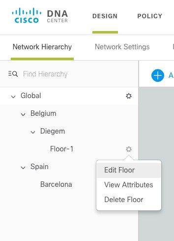
21 Step 2 Import Site maps from Prime. Step 3 Add Floor Map. 21
22 22
23 Network Settings DNAC allows you to save common resources and settings with Design's Network Setting application. This allows information pertaining to the enterprise to be stored so it can be reused throughout DNAC. DHCP, DNS Servers and Device Credentials should already be defined under here. Creating IP Pools Please configure IP pools manually for both your APs as well client subnets as per your network addressing scheme on your DHCP server. Additionally, ensure you have DHCP option 43 defined in your DHCP server for the AP IP pool to allow AP registration with WLC. DNAC does not provide automation for this step as this guide doesn t leverage the IP address Manager (Infoblox) integration. Procedure Using the menu navigate to Design > Network Settings select IP Address Pools. Click on Add to open a dialog for creating new IP Pools. 23

24 When complete, the DNAC IP Address Pools for clients and AP should look very similar to the following page: Creating Wireless SSIDs Procedure Step 1 Under Network Settings, click on Wireless tab. 24
25 Creating a SSID is a two-step process. First, create a wireless network by choosing the type of network and assigning a security type; second, create or assign a Wireless Profile. If a new profile is created, add sites where you want this SSID to be broadcasted. See the steps below to follow the workflow. Step 2 Click on Add SSID ("Internal03" in this example) and create SSID security WPA2 Enterprise. Fast Transition (802.11r) can be configured in SSID creation phase. Note In all the pictures in this Guide, names for SSIDs, Profiles, Pools, etc. are just for references and the users can pick their own. Step 3 Click Next. If not configured already, DNAC will prompt the user to create a Network profile to associate to the SSID. If already present, the user can select one of the existing profiles. The network profile defines the type of SSID, Fabric or non-fabric and the sites where it will be broadcasted. When creating a new Profile, under Design click on Network Profile and click on Add Profile. 25
26 Step 4 You can also create a new Profile outside the SSID flow: go under Design click on Network Profile and click on Add Profile. Select wireless as type and the give the Profile a name and add the SSIDs you want (add "Internal03" in this case). Click save. Note You can choose any name for your Profile. Above screen shot is for your reference. Step 5 Going back to the SSID configuration, edit the Profile to specify if Fabric or not and to add Locations where the SSIDs in this profile will be broadcasted. In the example shown below, SSID Internal03 is mapped site Diegem, the children sites (Floor-1) will inherit the settings. Just type the first letters of the site to see it appearing. Once the profile is configured you can click Save and return to the main SSID page. 26
27 Step 6 You can now create a Guest SSID. Under Guest Wireless click on Add icon to add a Guest SSID. Note Only ISE is supported as Authentication Server and Portal in DNAC 1.1 Step 7 Add the SSID to a Network Profile as you have done for the non guest SSID. 27

28 Step 8 DNAC offers backend integration with ISE for Portal and Profiles configuration. Screen shot below shows available option for Portal customization. Central Web Auth (CWA) with ISE is supported. Step 9 Click Finish to terminate the Guest SSID design phase. Step 10 Optionally the user can configure a customized RF profile. The Profile in the Design Phase and then applied in the Provisioning phase (see later in the doc). To create a RF profile, scroll down the wireless page and view the available Radio Profiles. 28
29 To create a new profile, click Add. The following page is displayed. Choose customization parameters (Dynamic Bandwidth Selection, DCA channel flexibility and HD RF settings) for the Parent Profile on 2.4/5 GHz band. 29
30 SD Access Policy In SDA, the network policy is a Group based policy based on Cisco TrustSec. Virtual Networks (equivalent of VRFs) and Scalable Group Tags (SGTS)are used to provide a hierarchical network policy and segmentation: at a macro level you can use VNs to completely separate groups of users from a control plane and data plane prospective. This is a stateful segmentation as usually to allow inter-vrf traffic, you would go through a Firewall. Within the Virtual Network, SGTs allow customers to implement a micro segmentation and define a stateless policy between users based on Secure Group ACLs. The beauty of SDA is that this applies to both wired and wireless users. Procedure Step 1 Create a new Virtual Network (VN) by clicking on the + icon, choose a name and assign Scalable Groups to the VN. This is an Optional step. 30
31 Note The reason you might want to add Groups (SGTs) to a VN at this point will be clear in the onboarding section: if you want to statically assign an SGT to an SSID or a port, you can do it through a pool association and when selecting the SGT you can choose from the ones you have included in the VN at this point. Step 2 Step 3 Click save to create the VN. Upon successful creation, you will see a message popping up in the right bottom corner of the screen. Next, click on Contracts from the top menu. Contract is where you define what traffic is permitted between scalable groups. Click on the Add Contract icon on the top right corner of the window to open up the Contract editor as shown below. In this example, we have created demo access with permit action for a specific port/protocol, in this case HTTPs. Note the implicit Deny action, the user can change it to default Permit. By clicking Save the contract will be created. 31

32 32 The newly created Access Contract can now be seen along with the two defaults (permit and deny).
33 Note Above screenshot is for your reference only. You can name the Contract as per your choice and assign any permission to it. Step 4 Lastly, create a group based access policy using the contract (created above) to tie scalable groups as shown below. Go to Policy Administration > Group-Based Access Control. Step 5 Name the Policy. Select Source and Destination Scalable Groups from available and move them to the right side. Note SGT-based policies are by default unidirectional, if the same policy is needed in both directions, please select the enable bi-direction in the page below. 33

34 Note Above screenshot is for your reference only. Please create a policy depending on your selection of scalable groups. Step 6 Click on Add Contract and select the contract demo-access created in Step 5. Step 7 View the created policy under Policy Administration > Group-Based Access Control. Step 8 The created policy between scalable groups and the SGACL is pushed from DNAC to ISE and can be viewed there. 34
 Provisioning Procedure Step 1 From the top menu select the Provisioning tab.")
35 Figure 5: SD-Access Overlay Provisioning In the Provisioning section, the network configurations are actually pushed to the devices. Device (WLC) Provisioning Procedure Step 1 From the top menu select the Provisioning tab. From here begin the provisioning process by selecting the Wireless LAN Controller and associating it to the sites previously created during the Design phase. 35
36 Step 2 Begin by selecting the WLC using a single click. Once selected choose the action "Add to Site" and assign it to the location where WLC is physically located. This step is important to assign the WLC to a regulatory domain corresponding to the site where it is physically located. The site needs to be a building or a floor, so a site with coordinates. Note Above screenshot is for your reference only. Please select your network WLC. 36
37 Note If the user wants to configure SSO HA, the second WLC needs to be added to the same site at this point. Then from the same Device Inventory page, click on the WLC you want to configure as primary and go to the High Availability TAB. Here enter the Management and Redundancy Management information for both Primary and Secondary controller and then click ok. The Controllers will reboot and after some time you will see only one WLC in the inventory. From now on, you can continue to provision as if it was a single WLC. Step 3 Once WLC is added to the site, with the Wireless Controller selected, click on Provision Action. Step 4 Select the AP locations managed by this Wireless LAN Controller. If any, here is important to select the floors where you will have APs deployed. Click Next. 37

38 Step 5 Review the configuration System Details, Global Settings for AAA, DHCP, DNS servers, SSID and Managed Sites that will be pushed as part of WLC provisioning from DNAC. Click Deploy. Step 6 Config pushed through DNAC can be viewed on the WLC such as RADIUS server pushed for authentication and accounting. Also, two WLANs are created with WLAN ID >17 and status disabled, one for each site the WLAN is associated with. The WLANs will be in disable state until the user configure Host Onboarding and assign a Pool to the SSID. 38

39 Note Above screenshots from WLC are for your reference only. You will see your network related config (ip address and names) on the WLC. Now that DNAC is aware of where devices reside within the sites you can begin the fabric provisioning. Creating Fabric Procedure Step 1 Step 2 Use the menu to select Fabric. You will be taken to a new page for creating and managing SD Access fabric. You can create a New Fabric or click on Default LAN Fabric. In the example below, we are have created a new Fabric called Diegem. Step 3 Click on Select Devices and add nodes to fabric. To add a device to Fabric, just click on the WLC and select "Add to Fabric". Hit Save after the wireless controller is added to Fabric. 39

40 Step 4 The devices should change color from grey to blue once they are added to Fabric as shown in the example below. Note Above screenshot is for your reference only. You may have multiple nodes as part of fabric. AP and Host Onboarding In this guide, it is assumed that the Fabric wired network has been provisioned already, so after adding the WLC it's time to onboard APs and wireless clients. For this, IP address pools need to be added to enable APs and wireless hosts to communicate within the fabric. When an IP pool is configured in SD Access, DNAC immediately connects to each edge node to create the appropriate SVI (switch virtual interface) to allow the hosts to communicate. In addition, an Anycast gateway is applied to all edge nodes. This is an essential element of SD Access as it allows hosts to easily roam to any edge node with no additional provisioning. Procedure Step 1 Click on the Host Onboarding at the top of this screen to start enabling the IP pools for AP and client devices. 40
41 Step 2 Click on INFRA VN, you will see a window open with configured address pools. Select the address pool for APs. Notice how AP Provisioning and Layer-2 extension are already turned ON for this INFRA_VN as both are needed to onboard APs Hit Update. Select the address pool for APs and turn On AP Provisioning Pool. Hit Update. Layer-2 Extension" setting enables L2 LISP and associates a L2VNID to this pool so that the Ethernet frame can be carried end to end on the Fabric. This is what allows to simulate a L2 stretched subnet service. Selecting "AP Provision pool" will automatically push a configuration macro to all the Edge Node switches; so, when the AP is directly connected, the switch will recognize it's an AP through CDP and the macro will be applied to the port automatically assigning the physical port to the right VLAN associated with the pool. The CDP macro on the FEs for AP onboarding is pushed only if the port no-authentication template is selected: 41
42 At the time of writing (DNAC 1.1), if any other switching port template is selected from above, then there is no automatic onboarding of APs. The admin will have to go the "Select Port Assignment" section at the bottom of the Host Onboarding page and assign manually the switchport where the AP is connected to the AP pool with Authentication set to No Authentication. An AP automatic onboarding method for the other Authentication templates is in the roadmap. Figure 6: At this point, the AP will be assigned to the right VLAN/Subnet and obtain an IP address from the specified pool and discover the WLC through one of the standard mechanisms (PnP, DHCP option 43, DNS, etc.) and then the AP joins the WLC. Provisioning the APs Now that the AP obtained an IP address and learnt the WLC's Management IP, the AP will join the WLC. Of course, this is under the assumption that there is IP connectivity between AP and WLC (this is outside the scope of this document and really depends on where the WLC is connected, usually outside of Fabric). Once the APs are registered to WLC, they will appear in the Inventory page on DNAC. Procedure Step 1 Next, go back to Provision > Devices > Inventory to see the APs joining the fabric enabled wireless controller. 42
43 Note Above screenshot is for your reference only. You may have different model 11ac wave2 Access Point in your setup. Step 2 Select AP from Device list and "Add to Site" as shown in the example below. Choose a floor where APs will be placed and click Assign. Make sure that the WLC that the APs are registered to has been provisioned to manage that floor. If the floor was added later, you can go back and Provision the WLC again to add the specific floor. 43
44 Step 3 Next, select AP from Device list and "Provision" the APs as shown in the example below. This time select Provision. Choose a Floor or just click Next if already selected. 44
45 Note You can add to a specific site to select "All Same Site" for the site to be mapped to all devices. Step 4 Choose a RF profile for the AP from High, Typical and Low or a customized one previously defined. In the example below, we have selected Typical and hit Next. Step 5 Click Deploy and as a part of AP provisioning, configuration will be pushed to AP as shown below. AP will reboot and rejoin the wireless controller. Click "Run now" in the window that pops up 45

46 A warning message pops up warning you that the APs will reboot. Click Ok Step 6 You will now see AP provision as success. Note Above screenshot is for your reference only. AP deployment details may look different on your setup. Step 7 As part of AP provisioning, some config pushed on WLC. An AP group will be created with the name of the site it was mapped to (step 3 above). AP and WLANs will be part of that AP group as shown in the example below. 46


47 Step 8 Next, you can place APs on floor maps and get coverage heatmap visualization. Go back to Design and select the floor under Network Hierarchy. Click on Edit and the click on Position. Example shown below. The two APs will appear in the corner and you can drag and drop them where they are located, next click Save. 47

48 Heat maps will be calculated and the result is shown below. You can click on the View Options to change things like Labels, map opacity and thresholds and so on. 48

49 Onboarding Clients Now we need to assign IP pools to wireless clients and SSIDs to have the clients actually join the network, follow the steps below: Procedure Step 1 Go to the Provision > Fabric. In this example, we are editing the Diegem Fabric, so click on that. Step 2 Click on Host Onboarding tab. 49
50 Step 3 Click on Internal03 VN (or whatever VN you are using for Clients) and from the available Address Pool, select the address pool for wireless clients. IMPORTANT: enable Layer-2 Extension. Click Update. Check the example below. Layer-2 Extension enables L2 LISP and associates a L2VNID to this pool. This is required. The traffic type setting (Data or Data + Voice) is only relevant for wired clients. The correspondent settings for wireless clients is done at the SSID level. Step 4 Associate the SSID with the pool that you have configured earlier (optionally you can also associate an SGT to be assigned to all the clients joining this SSID. 50
51 Onboarding Guest Clients For Guest SSID, the user will have two implementation choices (later, in the Guest Design session, the different available Designs are presented in more details): 1. Use the same Enterprise Guest CP node for Guest traffic: Guest SSID is associated to a dedicated Guest VN in Fabric and leverages Fabric segmentation (VNI, SGT) for guest traffic isolation 2. Dedicated a Guest Control Plane and Border for Guest: Before configuring the SSID, in both cases you need to mark the VN as Guest enabled. This tells DNAC that this is a special VN that needs to be configured accordingly. Got to Policy > Virtual Networks and create a new VN. Check the "Guest Virtual Network" checkbox as shown below and add the Scalable Groups that belong to this virtual network. Now, you can configure the SSID in the onboarding session. For the common Control Plane node, the procedure is the same as any other SSID configuration: simply click on Patients VN (or whatever VN you are using for Guest Clients) and from the available Address Pool, select the address pool for wireless clients and enable Layer-2 Extension. Click Update. Check the example below. 51
52 Then associate the Guest SSID with the pool as you have done in step 4 for the non guest SSID. If using a dedicated Border and Control Plane for Guest, then you need to add the Guest CP and Border to Fabric: click on the device icon and select enable Guest. The below window will pop-up and then you can select both Border and CP functionality. Also, the VN marked as Guest enabled will show up here. Internally DNAC will take care of the Fabric configuration to associate the Guest SSID with the pool and mapped that pool to the Guest CP and Border. 52


53 Step 5 Once you have associated the SSID with a pool in step 4, on the Wireless controller, you will see the SSIDs are now in the Admin Status Enabled. Note Above screenshot from WLC is for your reference only. WLAN name, security may be different in your setup. Step 6 Clients can now be connected to fabric enabled wireless SSID. You can go to your WLC and check connected client details. You can see if the client Fabric status and the SGT tag pushed to the WLC from ISE based on the authorization rule. Client details for user employee: Client details for user contractor. 53

54 Configuring Multicast To enable multicast for wireless multicast in wired network needs to be configured first. DNAC makes it very easy to configure both as outlined in the steps below. Note Multicast over wireless needs to be considered with some caution. Once Multicast IP traffic gets to the AP, these packets are transmitted over the air as broadcast Layer 2 frames; this basically means traffic gets transmitted at the highest mandatory data rate (to be able to reach all connected clients), and the transmission frames are not acknowledged so a collision in the air will result in the loss of the frame. This has implications on the achievable throughput for multicast traffic over the air. In order to improve the performance and reliability of multicast traffic over Wi-fi, Cisco has developed the VideoStream feature which coverts multicast frames into unicast frames at the AP, solving the problems mentioned above. The support for VideoStream (also known as multicast to unicast feature) is committed for a future release for SD-Access Wireless. Procedure Step 1 Configure a fabric node as a Rendezvous Point. This is done by going under Provision> Fabric, clicking on a device and choosing "Make Rendezvous point". Hit Save after making the change. 54
55 Step 2 Next, you will be prompted to enable multicast in the VRF of your choice. In the screenshot below, we have enabled multicast in DEFAULT_VN. Step 3 Next, go to Host Onboarding tab and you will notice the virtual network enabled for multicast marked with a red M icon indicating Multicast. Also, Enable Wireless Multicast checkbox as shown below. 55
56 Step 4 Click on the virtual network (DEFAULT_VN in the example below) and select Pool type as Multicast Pools and click Next. Step 5 Click on the multicast IP pool (created earlier in the Design phase under Network Settings> IP Address Pools) and click Update as shown below. 56

57 SD Access Wireless A Look under the Hood In this section, the basic operations of SD-Access Wireless are described and explained so that the reader has a clear understanding of what happens "behind the scenes" of DNAC. This flow assumes that the user is done with the Design phase and just focus on implementation, provisioning phase. Adding WLC to Fabric 1. In DNAC, first provision and then add WLC to Fabric Domain 2. Fabric configuration is pushed to WLC. WLC becomes Fabric aware. Most importantly WLC is configured with credentials to established a secure connection to the Fabric Control Plane (CP) 3. WLC is ready to participate in SD-Access Wireless 57

58 AP Join Flow 1. Admin user configures a pool in DNAC to be dedicated to APs in the INFRA_VN (this means checking the "AP Provisioning" box in the pool definition". DNAC pre-provision AP VLAN and related port macro on the FEs. 2. AP is plugged in and powers up. FE discovers it's an AP through CDP and applies the configuration macro to assign the switch port to the right VLAN. 3. AP gets an IP address through DHCP. AP is a "special " wired host to Fabric. Note As of DNAC 1.1 (November release), the CDP macro is pushed only when the No Authentication switchport template is selected during Host onboarding configuration. This is shown in picture below. This is shown in picture below. If any other Auth template is selected, then the admin user would have to statically map the APs' switch ports to the right IP pool. Going back to AP onboarding: 58
 and joins the WLC. Fabric AP joins as a Local mode AP 3.")

 8.")
59 1. Fabric Edge registers AP's IP address in the Control Plane node. AP location is now known in Fabric. 2. AP learns about WLC using traditional methods (DHCP option 43, DNS, PnP) and joins the WLC. Fabric AP joins as a Local mode AP 3. WLC checks if it is fabric-capable (Wave 2 or Wave 1 APs) 4. If AP model is supported, WLC queries the CP to know if AP is connected to Fabric 5. CP replies to WLC with the RLOC info. This means AP is attached to Fabric and will be shown as Fabric Enabled in the WLC AP details information 6. WLC does a L2 LISP registration for AP in HTDB (a.k.a. AP special secure client registration). This is used to pass important metadata information from WLC to the FE) 7. In response to this proxy registration by WLC, CP notifies the Fabric Edge and pass the metadata received from WLC (flag that says it's an AP and the AP IP address) 8. Fabric Edge processes the information, it learns that this client is an AP and creates a VXLAN tunnel interface to the specified IP (optimization: switch side is ready for clients to join) 59
, updates AP with client L2VNID and SGT. WLC knows RLOC of AP from its own internal record (saved during AP join) 2.")

 7.")
60 Client On-boarding Flow 1. Client authenticates to a Fabric enabled WLAN. WLC gets client SGT from ISE (assuming WLAN is configured for 802.1x authentication), updates AP with client L2VNID and SGT. WLC knows RLOC of AP from its own internal record (saved during AP join) 2. WLC proxy registers Client L2 info in CP; this is LISP modified message to pass additional info, like the client SGT 3. FE gets notified by CP and adds client MAC in L2 forwarding table and fetches policy from ISE based on SGT 4. Client initiates DHCP Request 5. AP encapsulates it in VXLAN with L2 VNI info 6. Fabric Edge maps L2 VNID to VLAN and VLAN interface and forwards DHCP in the overlay using Anycast IP as DHCP relay (same as for a wired Fabric client) 7. Client receives an IP address from DHCP 8. DHCP snooping (and/or ARP for static) triggers a client register by the Fabric Edge to the HTDB This completes Client onboarding process 60
 to add the client MAC to forwarding table pointing to VXLAN tunnel 2.")
 in CP upon receiving traffic Roam is Layer 2 as FE2 has the same VLAN interface (Anycast GW) Designing the Wireless integration in SD-Access As mentioned before,")
61 Client Roaming Flow 1. Client roams to AP2 on FE2 (inter-switch roaming). WLC gets notified by AP2 2. WLC updates forwarding table on AP with client info (SGT, RLOC IP address) 3. WLC updates the L2 MAC entry in CP with new RLOC FE2 4. CP then notifies 1. Fabric Edge FE2 ("roam-to" switch) to add the client MAC to forwarding table pointing to VXLAN tunnel 2. Fabric Edge FE1 ("roam-from" switch) to do clean up for the wireless client 3. Fabric Border to update internal RLOC for this client 5. FE will update the L3 entry (IP) in CP upon receiving traffic Roam is Layer 2 as FE2 has the same VLAN interface (Anycast GW) Designing the Wireless integration in SD-Access As mentioned before, there are two possible designs to deploy wireless with SD-Access Fabric: 1. CUWN Wireless Over The Top (OTT): SD-Access Fabric is just an IP transport network and wireless is a pure overlay 2. SD Access Wireless: wireless is integrated in SD-Access and can leverage all the advantages of Fabric Let's consider the different design considerations for the two different deployments. Before doing that, let's clarify what interfaces of the WLC are used and how in the different deployments. CUWN Wireless Over the Top (OTT) In this case traditional wireless is carried on top of SD-Access Fabric. This mode is important as a migration step for customers that decide to implement SDA first on the wired network and then plan the wireless integration. 61

62 Figure 7: CUWN Wireless OTT Traditional CUWN architecture with CAPWAP for Control Plane and Data Plane terminating at the WLC (for Centralized mode) SDA Fabric is just a transport in the wired infrastructure between the APs and the WLC This is a possible migration step to full SDA adoption Let's consider the different design considerations for the two different deployments. Before doing that, let's clarify what interfaces of the WLC are used and how in the different deployments. Wireless LAN Controller Interfaces For both SDA integration modes, let's consider the WLC interfaces as they apply to SD-Access Wireless and OTT. 62

63 In first release, the Wireless LAN Controller is connected in the underlay network (Global Routing Table) outside the Fabric network; The APs when connected to a Fabric network are assumed to be in the overlay, in other words the ports of a Fabric Edge are all fabric enabled port. It is not supported to have some ports connect in the overlay and some other ports connected in the underlay. The Management interface is used, as usual, for WLC to APs CAPWAP Control channel and to talk to shared services like AAA, DNAC, etc. When deployed using SD-Access Wireless, the Management interface is also used to integrate with the Control Plane node. The RP or redundancy port is used for HA communication between an Active and Standby HA Pair in order to provide seamless and stateful switchover in the event of a box or network failure. The Dynamic interfaces are only used if wireless is deployed over the top, meaning that the Fabric infrastructure is just a transport for the CAPWAP control and data channels to be transported back to the WLC for centralized processing. Service port is used for out-of-band management as usual. CUWN Wireless OTT Network Design First of all, what is CUWN Wireless OTT? In this mode, traditional CAPWAP tunnels between APs and WLC run as over lay to the Fabric network, in other words Fabric is a transport for CAPWAP. Why customer would deploy CUWN Wireless OTT? Mainly two reasons: 1. OTT solution can be a migration step: customers want/need to first migrate the wired infrastructure to SD-Access Fabric and keep the wireless network as is, meaning not touching the way wireless works today. This could be the result of different IT Operation teams managing the wired and wireless infrastructure, different buying cycle that determine first an upgrade on the wired network or simply the IT team want to first get familiar with Fabric on the wired side before they integrate the wireless part. 2. Another reason for deploying wireless OTT could be that customer doesn t want or cannot migrate to Fabric for wireless. This might be because they have a majority of older APs (802.11n or older) which are not supported with SDA, or the customer requires a certification of the new WLC software which is required to run SD-Access Wireless (8.5 and above) or simply because customer wants to leave the wireless as is and don t touch it. Let's consider some of the most important design consideration for each component. WLC Controller At FCS, the recommendation is to connect the WLC (or WLCs for redundancy) outside Fabric as shown in the picture above. This is the way it has been tested and hence it is supported. Usually the WLC is connected in a centralized place in the network (Data Center or shared Services) so it's realistic that the WLC is not connected to a Fabric Edge node which is usually an access switch. 63
 and the APs' IP pool (10.1.0.0/16 in this example) so that the CAPWAP tunnel can form and AP register to the WLC. In DNAC 1.")

64 Since the WLC sits outside Fabric, the Border node is responsible for providing reachability between the Management Interface subnet ( /24 in this example) and the APs' IP pool ( /16 in this example) so that the CAPWAP tunnel can form and AP register to the WLC. In DNAC 1.1 the APs resides in INFRA_VRF which is mapped to the global routing table, so route leaking is not needed. Note At FCS, Cisco only supports CUWN Centralized mode to be an overlay to Fabric. FlexConnect mode will be supported in future release. Access Points Access Points are simply wired hosts to the Fabric infrastructure and hence are connected to the overlay space on Fabric Edge switches and assigned a specific pool in the EID space. One of the advantage of Fabric is that all the APs can be assigned to one big subnet which is the same across the Campus simplifying subnet design and hence the onboarding operations. Since APs are like wired clients, they get registered in the Fabric Control Plane node (CP) by the Fabric edge switch they are connected to and hence their location will be made known in Fabric and APs will be reachable. At this point, the CAPWAP tunnel is formed from the AP to WLC over Fabric, as shown in the picture below: 64


65 Wireless LANs As mentioned, wireless works "as is" meaning that Wireless SSIDs on the WLC are mapped to VLAN/Subnet at WLC in the form of dynamic interfaces and wireless traffic enters the wired network at the WLC and is routed from there. Border node advertises the wireless client subnets to the Fabric so that connectivity can be established between a Fabric host and a wireless client. The flow of traffic is shown in the next paragraph. Client traffic Flow As a wireless client sends some traffic, the CAPWAP tunnel is built from the AP to the WLC. From the AP, the CAPWAP traffic hits the Fabric Edge switch, gets encapsulated in VXLAN and forwarded to Border. The outer VXLAN header is removed and underlying CAPWAP packet is forwarded to the WLC As with CUWN, clients are authenticated and on boarded by WLC and the wireless client traffic is external to Fabric. The diagram below shows the traffic flow for a communication between a wireless client and a local Fabric wired host: Figure 8: The wireless traffic will go all the way to the WLC, will be bridge at the WLC dynamic interface VLAN and routed back to the Fabric client through the Border. For wireless, this is the same thing that happens today with a normal wired network; for the Fabric, it is a Fabric host communicating to a known destination external to the Fabric. 65

66 Wireless as an Overlay (OTT) Design considerations Let's recap some of the important design considerations for OTT mode: All APs and WLC models are supported. Since wireless is not integrated in Fabric, there is no requirements on the hardware and software models The Controller is connected external to Fabric and can be on any code version It is recommended to increase the MTU along the path to prevent fragmentation of packets due to double (CAPWAP in VXLAN) encapsulation. This is done automatically if all the switches in the path are Cisco and support jumbo frames. At FCS, the only mode supported as OTT is Centralized. At FCS, use Cisco Prime to manage OTT wireless networks. SD-Access Wireless Network Design In order to gain all the advantages of SD-Access Fabric, customers should choose the integrated design and hence the SD-Access Wireless solution. From an Architecture prospective, the integration brings three main advantages: 1. Simplified Management and Control Plane: DNAC provides the necessary automation to bring up the Fabric and configure the wireless integration in few clicks. The Centralized Wireless Control plane (based on CAPWAP) provides the same functionalities of today s CUWN controller. 2. Optimized Data plane: data plane is distributed without the usual caveats that this usually brings; thanks to Fabric, there is no VLAN spanning multiple access switches and subnetting is simplified. 3. Integrated Policy and Segmentation end-to-end: Policy is not an afterthought, it is integrated from the ground up in the architecture. The VXLAN header carries both the VRF (VNID) and SGT information providing an end-to-end hierarchical segmentation. The advantages of the integrated design are summarized in the picture below: 66


67 Let's briefly analyze the Design aspects for the wireless integrated solution Controller At FCS, the recommendation is to connect the WLC (or WLCs for redundancy) externally to Fabric as shown in the picture above. Usually the WLC is connected in a centralized place in the network (Data Center or shared Services) so it's realistic that the WLC is not connected to a Fabric Edge node which is usually an access switch. Since the WLC sits outside Fabric, the Border node is responsible for provide reachability between the Management Interface subnet ( /24 in this example) and the APs' IP pool ( /16 in this example) so that the CAPWAP tunnel can form and the AP can register to the WLC. In DNAC 1.1 the APs resides in INFRA_VRF which is mapped to the global routing table, so route leaking is not needed. Also, the WLC needs to be co-located with the Access Points. The requirement is the same we have for Local mode APs in CUWN: the max latency between APs and WLC needs to be less than 20 ms, which usually means that WLC cannot be sitting across a WAN from the APs. 67

 by the Fabric edge switch they are connected to and hence their location will be made known in Fabric and")
68 Access Points In SD-Access Wireless, APs need to be directly connected to the Fabric Edge nodes. Access Points are "special" wired hosts to the Fabric infrastructure and hence are connected to the overlay space on Fabric Edge switches and assigned a specific pool in the EID space. One of the advantage of Fabric is that all the APs can be assigned to one big subnet which is the same across the Campus simplifying subnet design and hence the onboarding operations. Since APs are like wired clients, they get registered in the Fabric Control Plane node (CP) by the Fabric edge switch they are connected to and hence their location will be made known in Fabric and APs will be reachable. The AP will form a CAPWAP tunnel to the WLC for Control plane functionalities in the same way it has been described for OTT design. Wireless LANs Fabric capability is enabled on a per WLAN basis. For the WLAN that are Fabric enabled, the client traffic is distributed and will not go to the centralized controller but it will be encapsulated in VXLAN at the AP and sent to the first hop switch. Centralized CAPWAP WLANs can co-exist with Fabric-enabled WLANs on the same or different APs using a common Fabric-enabled WLC. This is called mixed mode and with DNAC 1.1 it is support for WLC deployment with no preexisting Fabric or CUWN wireless configuration, so for new deployments only. Client flow For Fabric enabled SSIDs, the wireless client traffic is distributed at the switch so there is no air-pinning to the centralized controller. The communication to wired clients is directly through Fabric and hence optimized. 68


69 Client subnets are distributed at the Fabric Edge switches and there is no need to define dynamic interfaces and client subnets at the WLC. Instead client subnets are defined and mapped to VLAN with Anycast Gateway at all Fabric Edge switches. This means that no matter where the wireless client connects, it will be able to talk to the same gateway for its subnet, which means that the client will be able to retain its original IP address everywhere; in other words, all wireless roams in Fabric are Layer-2 roams. SD-Access Wireless Guest Access Design When considering Guest Design, the integration with Fabric offers three different solutions: 1. The OTT solution leveraging Guest Anchor Controller 2. Dedicated Guest Virtual Network 3. Dedicated Guest Fabric domain OTT solution leveraging CUWN Guest Anchor 69


70 Customer can continue to leverage the investment done on Guest Anchor Controllers by deployment the Guest wireless network as Over The Top (OTT). The WLAN for Guests will be configured to be anchored at Guest Anchor in DMZ and the traffic will be an overlay to Fabric. This is a well proven CUWN solution, protecting the customer investment and particularly suited for brownfield deployments. Of course, this solution has the limitations partially inherited from the CUWN solution: Restriction of 71 Guest Tunnels Separate solution for Wired Guest, Anchor WLC managed differently Note There is no automation for this option in DNAC 1.1; the DNAC support is in the roadmap. Dedicated VN for Guest In this Design, the Guest network is just another Virtual Network in SD-Access Fabric, so leveraging end-to-end fabric segmentation (using a VNI, and SGTs for different Guest roles if needed) to separate the Guest data plane from the other Enterprise traffic. It's configured through DNAC by creating a Guest Virtual Network, defining the IP pools and associating the SSID to one or more pools for guests. One of the main advantage over the previous solution is that this is a consistent solution and policy for Wired and Wireless guest users. Guest as a separate Fabric Domain If the customer requires complete isolation for the Guest network, not only for the data plane traffic, but also in terms of Control Plane, then in DNAC you can configure a dedicated Guest Control Pane and border (so essentially a dedicated Fabric Domain) to manage guest users. In this solution the traffic is still encapsulated at the AP in VXLAN to the Fabric edge switch, but then the FE is configured to use a different Border node. This Border can reside in the customer DMZ providing a complete traffic isolation, similar to the one we have with the Guest anchor solution. The guest users will be registered in a dedicate CP (that may be collocated with the Border or not) and the users will get an IP address in the DMZ. Similar to the previous VN solution, this Design provide policy consistency for wired and wireless guests. The choice of Guest CP and Border will depend on the scalability of the solution. 70
71 Multicast in SD-Access Wireless Important things to know about Multicast in SD-Access: Multicast traffic is transported in the overlay, in the EID space, for both wired and wireless clients To enable multicast for wireless, Global Multicast mode and IGMP snooping need to be enabled globally on the WLC At FCS, multicast traffic leverages head-end replication to forward traffic to the Fabric multicast destination. This means that the underlay network doesn t need to be multicast enabled. This method is not optimal as multicast traffic coming into the Fabric is replicated in multiple unicast VXLAN tunnels, one for each Fabric edge node that has some multicast receiver attached Let's now explain how Multicast works: The Multicast client (receiver) is in the overlay, the multicast source can be outside Fabric or in the overlay as well (in the diagram the source is shown outside Fabric) PIM-SM/PIM-SSM needs to be running in the Overlay (so needs to be enabled per VRF) The client sends IGMP join for a specific multicast Group (G) AP encapsulates it in VXLAN and send it to the upstream switch The Fabric Edge node (FE) receives it and does a PIM Join towards the Fabric Rendezvous Point RP (assuming PIM-SM is used) The RP needs to be present in the Overlay as part of the End point IP space Here is the representation of the above steps: 71
 The RP now has the source and receiver information for that multicast group")
72 72 Being outside of Fabric, in this example the Multicast source will send the multicast traffic on the interfaces towards the Fabric Border (FB) which is the Designated Router (DR) for that segment The FB receives the traffic and does a PIM Join towards the RP (assuming PIM-SM is used) The RP now has the source and receiver information for that multicast group

73 The RP now has the source and receiver information for a particular multicast group. The FB will send the multicast source traffic over a VXLAN tunnel to the RP and the RP will forward that traffic to the FE over another VXLAN tunnel FE receives the VXLAN packets, decapsulates, applies policy and then forwards it again to the AP over an VXLAN tunnel The AP removes the VXLAN header and send the original IP multicast packet into the air 73

74 Once the first multicast packet is delivered to the FE the shortest path failover (SPT) happens and the traffic is forwarded between the FB and the FE directly The FE knows that the FB owns the multicast source based on the first multicast packet received and send a PIM join directly to the FB for that multicast group FB now knows which FEs have clients that requested the specific multicast Group It performs headend replication and VXLAN encapsulates the multicast traffic and unicasts it to the interested FEs The multicast traffic is sent in the overlay FE receives the VXLAN packets, decapsulates, apply policy and then forwards it again to the AP The AP removes the VXLAN header and send the original IP multicast packet into the air High Availability in SD-Access Wireless For SD-Access Wireless solution the most critical components are the WLC and the Control Plane node. Compared to wired fabric clients, the CP plays even a more important role for wireless as it plays a critical role for client roaming as it is responsible for keeping the updated client location information. Both WLC and the CP support High Availability for providing a SD-Access reliable solution. 74

75 Controller Redundancy Controller high availability using N+1 and SSO are both supported for the Fabric aware controller. Stateful Redundancy with SSO WLC SSO pair is seen as one node by Fabric Only Active WLC interacts with CP node Fabric configuration and CP state is synched between Active and Standby WLC Upon failure, new Active WLC will bulk update Fabric clients to the HTDB node (LISP-refresh) APs and Clients stay connected As seen in the Design section, at FCS WLC is connected outside Fabric, so the usual consideration for connecting an SSO pair will apply: the bandwidth and latency requirements between the two controllers are the same as in the CUWN architecture 75

76 Stateless Redundancy with N+1 N+1 redundancy is also supported if customer doesn't need stateful HA. N+1 redundancy is not automated through DNAC 1.1, the support for this functionality is in the DNAC roadmap. Here are the important considerations: AP is configured with Primary and Secondary AP and associated clients register with Primary Upon Primary failure, AP disconnects and joins Secondary Clients are also disconnected and join Secondary Secondary performs new client registration in HTDB Note N+1 redundancy is not automated through DNAC 1.1, the support for this functionality is in the DNAC roadmap. 76
 are configured with two CP nodes and synch information to both If one fails, all client information")

77 Campus Plane Redundancy Redundancy for the Control Plane node is supported in Active / Active configuration WLC (and the Fabric Edges) are configured with two CP nodes and synch information to both If one fails, all client information is available at the other CP node Here is the configuration on the WLC for reference: Appendix: SD-Access Wireless Features deep dive The following table captures some of the key features supported on the SD-Access Wireless Architecture. 77
78 Table 1: Key feature support with SD-Access Wireless Architecture Open/Static WEP WPA-PSK 802.1x (WPA/WPA2) MAC Filtering Local EAP AAA Override Internal/External Webauth Pre-auth ACL IPv4 ACL for Clients AVC Local Profiling RADIUS profiling QoS Profiles Per-user BW contracts wips CMX integration Netflow Export HA SSO Supported Supported Supported Supported Supported Supported Supported Supported Supported (SGT are preferred and recommended) Supported* Supported Supported Supported Supported Supported Supported Supported Supported *Wave2 APs only Let's explain some of the features in a more detail to understand how they work in a Fabric network. AAA Override ISE can override parameters Fabric Interface Name, ACL, QoS, SGT on an SD-Access Wireless SSID Fabric Interface Name Override What if the customer wants to have the same SSID mapped to different pool/subnets based on client authentication and role? In CUWN we use VLAN override for this passing the VLAN ID (name or number) from the AAA server back to the WLC. In Fabric, the VLAN has only a local switch meaning and what the IP pool is mapped to is a L2 Virtual Network ID (L2VNID). This is the network identifier that is associated with a subnet/pool and for wireless to an SSID; L2 VNID is transported from the AP to the switch in the VXLAN header. The L2 VNID is ultimately mapped to a VLAN locally at the Fabric Edge switch and to a SVI interface (Anycast gateway) and hence to a L3 VNID (VRF). In SD-Access Wireless we need to pass the L2VNID to differentiate different pools. Since ISE or other AAA don't use VNIDs directly, we use the Cisco AVP Aire-Interface-Name or Interface-Name to return a specific name at the time of client authentication. The client L2 authentication always happens at the controller, so it's the WLC that talks to ISE and gets that interface name value and maps it to a L2VNID. 78


79 In ISE the user needs to configure the specific Group authorization profile to return the specific interface name as you can see in the picture below, so when the user authenticates, ISE will return the specific attribute in the Radius ACCEPT_ACCEPT message The Fabric Interface Name is then mapped to L2 instance ID using the mapping as shown below. Important: all this mapping and configuration happens automatically when the user configures DNAC. Figure 9: Interface name to L2 VNID Mapping 79

80 The L2 instance ID is sent down to the AP to embed it into the VXLAN header. ACL and QoS Profile AAA Override Fabric ACL on WLC will be applied on the AP. The main difference between Local WLC ACL and Fabric ACL lies in the fact that Fabric ACLs do not have a direction associated with it. On the Fabric SSID, Flex ACL will be configured on SSID.The same ACL will be applied on both ingress and egress. For AAA Override of ACL: Override ACL name must be a Fabric ACL (Flex ACL) on the AP ACL Templates can be used to push ACLs to APs Figure 10: ACL Template creation Figure 11: ACL Template association with AP Group Note Although IP ACLs are supported, the recommended way to apply a security policy in SD-Access is with SGTs 80

81 For QoS Profile Name override: QoS Profile name is pushed from ISE Upstream and downstream QoS is applied at the AP VXLAN tunnel QoS is picked from the inner header Group Based Policies with SGT WLC sends to the AP an SGT to use for the wireless client when the client joins. The AP puts this SGT in the VXLAN header when it forwards data packets from the wireless client to the access switch over the VXLAN tunnel. This SGT tag is carried end-to-end through the fabric. Figure 12: VXLAN header includes SGT and VNI At the egress access switch, (SGT, DGT) pair determines the SGACL to be applied. SGT comes from the packet and the DGT is derived based on the destination host ip binding. For applying the SGACL on the access switch for wireless clients (enforcement for the traffic destined to wireless client on the access switch (VXLAN tunnel source), The TAG (SGT tag AKA as DGT) need to be learned on the Switch. The following steps describe the flow for group-based policies: Client L2 authentication happens at the WLC WLC sends SGT to AP at Client Join WLC Updates CP with SGT at client registration CP updates FE with SGT in Opaque data. Based on the received SGT, the switch goes and download the policy from ISE AP puts this SGT in the VXLAN header SGT tag is carried end-to-end through fabric in LISP Header At egress switch (SGT, DGT) pair determines SGACL based on SGT in packet header 81
 is described.")
82 Figure 13: SGT for Group Based Policy CWA and ISE for BYOD Here the basic flow for Central Web Authentication (CWA) is described. This is the only type of web authentication supported though DNAC automation. 82
 and a Redirect URL is pushed to the AP 3.")
83 Figure 14: Central Web-auth with ISE 1. L2 Authentication happens at the ISE server. MAC filtering is needed to be configured on the WLC 2. During the client authentication phase, a URL redirect ACL (Flex ACL type) and a Redirect URL is pushed to the AP 3. Client traffic is redirected to ISE portal for device registration and native supplicant provisioning on a VXLAN tunnel 4. Once complete, ISE sends a CoA to the WLC and the WLC pushes CoA to the AP 5. The client then re-authenticates using EAP-TLS. Since the device is now known to the ISE Server, the authentication goes thru and any further data Traffic is switched from the AP to VXLAN on to the Fabric Edge The flow is as follows: 1. L2 Authentication happens at the WLC and Client moves into WEBAUTH_REQD state 2. HTTP re-direct happens at the WLC 3. Web-auth can be internal (webpage hosted on WLC) or external (webpage hosted on external server) 4. Traffic matches the pre-auth ACL for external LWA and is switched out on the VXLAN tunnel. If internal WebAuth the traffic is sent to the WLC through CAPWAP 5. Once L3 authentication is complete, the client moves to RUN state and the pre-auth ACL is removed 6. Guest Data traffic is switched from FE to Guest Border node in the DMZ if internal WebAuth the traffic is sent to the WLC through CAPWAP Note All configurations need to be done directly on the WLC User Interface. 83
SD-Access Wireless: why would you care?
 SD-Access Wireless: why would you care? CUWN Architecture - Centralized Overview Policy Definition Enforcement Point for Wi-Fi clients Client keeps same IP address while roaming WLC Single point of Ingress
Software-Defined Access Wireless
 Introduction to, page 1 Configuring SD-Access Wireless (CLI), page 7 Enabling SD-Access Wireless (GUI), page 8 Configuring SD-Access Wireless VNID (GUI), page 9 Configuring SD-Access Wireless WLAN (GUI),
Software-Defined Access Wireless
 Introduction to, page 1 Configuring SD-Access Wireless (CLI), page 7 Enabling SD-Access Wireless (GUI), page 8 Configuring SD-Access Wireless VNID (GUI), page 9 Configuring SD-Access Wireless WLAN (GUI),
Software-Defined Access Wireless
 Introduction to, page 1 Configuring SD-Access Wireless (CLI), page 7 Introduction to The Enterprise Fabric provides end-to-end enterprise-wide segmentation, flexible subnet addressing, and controller-based
Več kot SDN - SDA arhitektura v uporabniških omrežjih
 Več kot SDN - SDA arhitektura v uporabniških omrežjih Aleksander Kocelj SE Cisco Agenda - Introduction to Software Defined Access - Brief description on SDA - Cisco SDA Assurance - DEMO 2 New Requirements
Tech Update Oktober Rene Andersen / Ib Hansen
 Tech Update 10 12 Oktober 2017 Rene Andersen / Ib Hansen DNA Solution Cisco Enterprise Portfolio DNA Center Simple Workflows DESIGN PROVISION POLICY ASSURANCE Identity Services Engine DNA Center APIC-EM
P ART 3. Configuring the Infrastructure
 P ART 3 Configuring the Infrastructure CHAPTER 8 Summary of Configuring the Infrastructure Revised: August 7, 2013 This part of the CVD section discusses the different infrastructure components that are
Cisco Campus Fabric Introduction. Vedran Hafner Systems engineer Cisco
 Cisco Campus Fabric Introduction Vedran Hafner Systems engineer Cisco Campus Fabric Abstract Is your Campus network facing some, or all, of these challenges? Host Mobility (w/o stretching VLANs) Network
Design Your Network. Design A New Network Infrastructure. Procedure
 Design A New Network Infrastructure, page 1 About Network Hierarchy, page 2 Create Sites in the Network Hierarchy, page 2 Add Floors to Buildings, page 3 Edit Floors, page 4 Place Cisco APs on a Floor,
Campus Fabric Configuration Guide, Cisco IOS XE Everest 16.6.x (Catalyst 9300 Switches)
") Campus Fabric Configuration Guide, Cisco IOS XE Everest 16.6.x (Catalyst 9300 Switches) First Published: 2017-07-31 Americas Headquarters Cisco Systems, Inc. 170 West Tasman Drive San Jose, CA 95134-1706
Campus Fabric Configuration Guide, Cisco IOS XE Everest 16.6.x (Catalyst 9300 Switches) First Published: 2017-07-31 Americas Headquarters Cisco Systems, Inc. 170 West Tasman Drive San Jose, CA 95134-1706
Campus Fabric Configuration Guide, Cisco IOS XE Everest 16.6.x (Catalyst 3650 Switches)
") Campus Fabric Configuration Guide, Cisco IOS XE Everest 16.6.x (Catalyst 3650 Switches) First Published: 2017-07-31 Last Modified: 2017-11-03 Americas Headquarters Cisco Systems, Inc. 170 West Tasman Drive
Campus Fabric Configuration Guide, Cisco IOS XE Everest 16.6.x (Catalyst 3650 Switches) First Published: 2017-07-31 Last Modified: 2017-11-03 Americas Headquarters Cisco Systems, Inc. 170 West Tasman Drive
Software-Defined Access Design Guide
 Cisco Validated design Software-Defined Access Design Guide December 2017 Solution 1.1 Table of Contents Table of Contents Cisco Digital Network Architecture and Software-Defined Access Introduction...
Cisco SD-Access Building the Routed Underlay
 Cisco SD-Access Building the Routed Underlay Rahul Kachalia Sr. Technical Leader Cisco Spark How Questions? Use Cisco Spark to communicate with the speaker after the session 1. Find this session in the
Configuring Hybrid REAP
 13 CHAPTER This chapter describes hybrid REAP and explains how to configure this feature on controllers and access points. It contains the following sections: Information About Hybrid REAP, page 13-1,
Configuring OfficeExtend Access Points
 Information About OfficeExtend Access Points, page 1 OEAP 600 Series Access Points, page 2 OEAP in Local Mode, page 3 Supported WLAN Settings for 600 Series OfficeExtend Access Point, page 3 WLAN Security
exam. Number: Passing Score: 800 Time Limit: 120 min CISCO Deploying Cisco Wireless Enterprise Networks. Version 1.
 300-365.exam Number: 300-365 Passing Score: 800 Time Limit: 120 min CISCO 300-365 Deploying Cisco Wireless Enterprise Networks Version 1.0 Exam A QUESTION 1 The customer has deployed C7960 phones with
Configure Devices Using Converged Access Deployment Templates for Campus and Branch Networks
 Configure Devices Using Converged Access Deployment Templates for Campus and Branch Networks What Are Converged Access Workflows?, on page 1 Supported Cisco IOS-XE Platforms, on page 3 Prerequisites for
Cisco Software-Defined Access
 Migration Guide Cisco Software-Defined Access 2017 Cisco and/or its affiliates. All rights reserved. This document is Cisco Public Information. Page 1 of 31 Contents Cisco SD-Access... 3 Evolution of Networking
Software-Defined Access 1.0
 White Paper Software-Defined Access 1.0 Solution White Paper Americas Headquarters Cisco Systems, Inc. 170 West Tasman Drive San Jose, CA 95134-1706 USA https://www.cisco.com/ Tel: 408 526-4000 800 553-NETS
DWS-4000 Series DWL-3600AP DWL-6600AP
 Unified Wired & Wireless Access System Configuration Guide Product Model: Release 1.0 DWS-4000 Series DWL-8600AP DWL-6600AP DWL-3600AP Page 1 Table of Contents 1. Scenario 1 - Basic L2 Edge Setup: 1 Unified
Software-Defined Access 1.0
 Software-Defined Access 1.0 What is Cisco Software-Defined Access? The Cisco Software-Defined Access (SD-Access) solution uses Cisco DNA Center to provide intent-based policy, automation, and assurance
Deploying Cisco Wireless Enterprise Networks
 300-365 Deploying Cisco Wireless Enterprise Networks NWExam.com SUCCESS GUIDE TO CISCO CERTIFICATION Exam Summary Syllabus Questions Table of Contents Introduction to 300-365 Exam on Deploying Cisco Wireless
Mobility Groups. Information About Mobility
 Information About Mobility, page 1 Information About, page 5 Prerequisites for Configuring, page 10 Configuring (GUI), page 12 Configuring (CLI), page 13 Information About Mobility Mobility, or roaming,
Cisco Catalyst 6500 Series Wireless LAN Services Module: Detailed Design and Implementation Guide
 Cisco Catalyst 6500 Series Wireless LAN Services Module: Detailed Design and Implementation Guide Introduction This is the first of a series of documents on the design and implementation of a wireless
Cisco Software-Defined Access
 Cisco Software-Defined Access Introducing an entirely new era in networking. What if you could give time back to IT? Provide network access in minutes for any user or device to any application-without
High Availability (AP SSO) Deployment Guide
 Deployment Guide") High Availability (AP SSO) Deployment Guide Document ID: 113681 Contents Introduction Prerequisites Requirements Components Used Conventions Topology New HA Overview HA Connectivity Using Redundant Port
High Availability (AP SSO) Deployment Guide Document ID: 113681 Contents Introduction Prerequisites Requirements Components Used Conventions Topology New HA Overview HA Connectivity Using Redundant Port
Configuring Cisco Mobility Express controller
 There are multiple ways one can configure a Cisco Mobility Express controller. They are as follows: 1 CLI Setup Wizard 2 Over the Air Setup Wizard 3 Network Plug and Play CLI Setup Wizard, page 1 Over-the-Air
Cisco.Network.Intuitive FastLane IT Forum. Andreas Korn Systems Engineer
 Cisco.Network.Intuitive FastLane IT Forum Andreas Korn Systems Engineer 12.10.2017 Ziele dieser Session New Era of Networking - Was ist darunter zu verstehen? Software Defined Access Wie revolutioniert
Service Graph Design with Cisco Application Centric Infrastructure
 White Paper Service Graph Design with Cisco Application Centric Infrastructure 2017 Cisco and/or its affiliates. All rights reserved. This document is Cisco Public Information. Page 1 of 101 Contents Introduction...
VXLAN Overview: Cisco Nexus 9000 Series Switches
 White Paper VXLAN Overview: Cisco Nexus 9000 Series Switches What You Will Learn Traditional network segmentation has been provided by VLANs that are standardized under the IEEE 802.1Q group. VLANs provide
CCIE Wireless v3 Lab Video Series 1 Table of Contents
 CCIE Wireless v3 Lab Video Series 1 Table of Contents Section 1: Network Infrastructure Layer 2 Technologies VLANs VTP Layer 2 Interfaces DTP Spanning Tree- Root Election Spanning Tree- Path Control Spanning
Using Access Point Communication Protocols
 Information About Access Point Communication Protocols, page 1 Restrictions for Access Point Communication Protocols, page 2 Configuring Data Encryption, page 2 Viewing CAPWAP Maximum Transmission Unit
Securing Wireless LAN Controllers (WLCs)
") Securing Wireless LAN Controllers (WLCs) Document ID: 109669 Contents Introduction Prerequisites Requirements Components Used Conventions Traffic Handling in WLCs Controlling Traffic Controlling Management
Securing Wireless LAN Controllers (WLCs) Document ID: 109669 Contents Introduction Prerequisites Requirements Components Used Conventions Traffic Handling in WLCs Controlling Traffic Controlling Management
Managing NCS User Accounts
 7 CHAPTER The Administration enables you to schedule tasks, administer accounts, and configure local and external authentication and authorization. Also, set logging options, configure mail servers, and
Identity Based Network Access
 Identity Based Network Access Identity Based Network Access - Agenda What are my issues Cisco ISE Power training What have I achieved What do I want to do What are the issues? Guest Student Staff Contractor
Campus Fabric. How To Integrate With Your Existing Networks. Kedar Karmarkar - Technical Leader BRKCRS-2801
 Campus Fabric How To Integrate With Your Existing Networks Kedar Karmarkar - Technical Leader Campus Fabric Abstract Is your Campus network facing some, or all, of these challenges? Host Mobility (w/o
Configuring FlexConnect Groups
 Information About FlexConnect Groups, page 1, page 5 Configuring VLAN-ACL Mapping on FlexConnect Groups, page 10 Configuring WLAN-VLAN Mappings on FlexConnect Groups, page 11 Information About FlexConnect
Cisco TrustSec How-To Guide: Universal Configuration for the Cisco Wireless LAN Controller
 Cisco TrustSec How-To Guide: Universal Configuration for the Cisco Wireless LAN Controller For Comments, please email: howtoguides@external.cisco.com Current Document Version: 3.0 August 27, 2012 Table
Cisco 8500 Series Wireless Controller Deployment Guide
 Cisco 8500 Series Wireless Controller Deployment Guide Document ID: 113695 Contents Introduction Prerequisites Requirements Components Used Conventions Product Overview Product Specifications Features
CertKiller q
 CertKiller.500-451.28q Number: 500-451 Passing Score: 800 Time Limit: 120 min File Version: 5.3 500-451 Cisco Unified Access Systems Engineer Exam I just passed today with 89%. My sole focus was the VCE.
Routing Underlay and NFV Automation with DNA Center
 BRKRST-1888 Routing Underlay and NFV Automation with DNA Center Prakash Rajamani, Director, Product Management Cisco Spark How Questions? Use Cisco Spark to communicate with the speaker after the session
Evolving your Campus Network with. Campus Fabric. Shawn Wargo. Technical Marketing Engineer BRKCRS-3800
 Evolving your Campus Network with Campus Fabric Shawn Wargo Technical Marketing Engineer BRKCRS-3800 Campus Fabric Abstract Is your Campus network facing some, or all, of these challenges? Host Mobility
Cisco Aironet 1815T (Teleworker) Access Point Deployment Guide
 Access Point Deployment Guide") Cisco Aironet 1815T (Teleworker) Access Point Deployment Guide First Published: 2017-08-18 Americas Headquarters Cisco Systems, Inc. 170 West Tasman Drive San Jose, CA 95134-1706 USA http://www.cisco.com
Cisco Aironet 1815T (Teleworker) Access Point Deployment Guide First Published: 2017-08-18 Americas Headquarters Cisco Systems, Inc. 170 West Tasman Drive San Jose, CA 95134-1706 USA http://www.cisco.com
FortiNAC. Cisco Airespace Wireless Controller Integration. Version: 8.x. Date: 8/28/2018. Rev: B
 FortiNAC Cisco Airespace Wireless Controller Integration Version: 8.x Date: 8/28/2018 Rev: B FORTINET DOCUMENT LIBRARY http://docs.fortinet.com FORTINET VIDEO GUIDE http://video.fortinet.com FORTINET KNOWLEDGE
Cisco ACI vcenter Plugin
 This chapter contains the following sections: About Cisco ACI with VMware vsphere Web Client, page 1 Getting Started with, page 2 Features and Limitations, page 7 GUI, page 12 Performing ACI Object Configurations,
Cisco 440X Series Wireless LAN Controllers Deployment Guide
 Cisco 440X Series Wireless LAN Controllers Deployment Guide Cisco customers are rapidly adopting the Cisco Unified Wireless Network architecture for next generation wireless LAN performance and advanced
TECHNICAL NOTE MSM & CLEARPASS HOW TO CONFIGURE HPE MSM CONTROLLERS WITH ARUBA CLEARPASS VERSION 3, JUNE 2016
 HOW TO CONFIGURE HPE MSM CONTROLLERS WITH ARUBA CLEARPASS VERSION 3, JUNE 2016 CONTENTS Introduction... 5 MSM and AP Deployment Options... 5 MSM User Interfaces... 6 Assumptions... 7 Network Diagram...
CMX Dashboard Visitor Connect
 CHAPTER 11 Cisco CMX Visitor Connect is a guest access solution based on Mobility Services Engine (MSE), Cisco Wireless LAN Controller (WLC) and Lightweight Access points (AP). The CMX Visitor Connect
Cisco SD-Access Hands-on Lab
 LTRCRS-2810 Cisco SD-Access Hands-on Lab Larissa Overbey - Technical Marketing Engineer, Cisco Derek Huckaby - Technical Marketing Engineer, Cisco https://cisco.box.com/v/ltrcrs-2810-bcn2018 Password:
CCIE Wireless v3 Workbook Volume 1
 CCIE Wireless v3 Workbook Volume 1 Table of Contents Diagrams and Tables 7 Topology Diagram 7 Table 1- VLANs and IP Subnets 8 Table 2- Device Management IPs 9 Table 3- Device Credentials 10 Table 4- Term
Real4Test. Real IT Certification Exam Study materials/braindumps
 Real4Test http://www.real4test.com Real IT Certification Exam Study materials/braindumps Exam : 400-351 Title : CCIE Wireless Vendor : Cisco Version : DEMO Get Latest & Valid 400-351 Exam's Question and
CCIE Wireless v3.1 Workbook Volume 1
 CCIE Wireless v3.1 Workbook Volume 1 Table of Contents Diagrams and Tables 7 Topology Diagram 7 Table 1- VLANs and IP Subnets 8 Table 2- Device Management IPs 9 Table 3- Device Credentials 10 Table 4-
DHCP. DHCP Proxy. Information About Configuring DHCP Proxy. Restrictions on Using DHCP Proxy
 Proxy, page 1 Link Select and VPN Select, page 4 Option 82, page 7 Internal Server, page 10 for WLANs, page 13 Proxy Information About Configuring Proxy When proxy is enabled on the controller, the controller
INTRODUCTION 2 DOCUMENT USE PREREQUISITES 2
 Table of Contents INTRODUCTION 2 DOCUMENT USE PREREQUISITES 2 LISP MOBILITY MODES OF OPERATION/CONSUMPTION SCENARIOS 3 LISP SINGLE HOP SCENARIO 3 LISP MULTI- HOP SCENARIO 3 LISP IGP ASSIT MODE 4 LISP INTEGRATION
Wireless LAN Controller Web Authentication Configuration Example
 Wireless LAN Controller Web Authentication Configuration Example Document ID: 69340 Contents Introduction Prerequisites Requirements Components Used Conventions Web Authentication Web Authentication Process
Cisco TrustSec How-To Guide: Central Web Authentication
 Cisco TrustSec How-To Guide: Central Web Authentication For Comments, please email: howtoguides@external.cisco.com Current Document Version: 3.0 August 27, 2012 Table of Contents Table of Contents... 1
WiNG 5.x How-To Guide
 WiNG 5.x How-To Guide Tunneling Remote Traffic using L2TPv3 Part No. TME-08-2012-01 Rev. A MOTOROLA, MOTO, MOTOROLA SOLUTIONS and the Stylized M Logo are trademarks or registered trademarks of Motorola
CCNA ICND Exam Updates
 Appendix B CCNA ICND2 200-105 Exam Updates Over time, reader feedback allows Pearson to gauge which topics give our readers the most problems when taking the exams. To assist readers with those topics,
Vendor: HP. Exam Code: HP2-Z32. Exam Name: Implementing HP MSM Wireless Networks. Version: Demo
 Vendor: HP Exam Code: HP2-Z32 Exam Name: Implementing HP MSM Wireless Networks Version: Demo QUESTION 1 A network administrator deploys several HP MSM APs and an HP MSM Controller. The APs discover the
Deploying LISP Host Mobility with an Extended Subnet
 CHAPTER 4 Deploying LISP Host Mobility with an Extended Subnet Figure 4-1 shows the Enterprise datacenter deployment topology where the 10.17.1.0/24 subnet in VLAN 1301 is extended between the West and
Implementing VXLAN. Prerequisites for implementing VXLANs. Information about Implementing VXLAN
 This module provides conceptual information for VXLAN in general and configuration information for layer 2 VXLAN on Cisco ASR 9000 Series Router. For configuration information of layer 3 VXLAN, see Implementing
Software-Defined Access Deployment Guide
 CISCO VALIDATED DESIGN Software-Defined Access Deployment Guide September 2018 Solution 1.1 Table of Contents Table of Contents Software-Defined Access introduction... 1 Implementation overview...2 Design
Universal Wireless Controller Configuration for Cisco Identity Services Engine. Secure Access How-To Guide Series
 Universal Wireless Controller Configuration for Cisco Identity Services Engine Secure Access How-To Guide Series Author: Hosuk Won Date: November 2015 Table of Contents Introduction... 3 What Is Cisco
Cisco Software Defined Access (SDA)
") Cisco Software Defined Access (SDA) Transformational Approach to Network Design & Provisioning Sanjay Kumar Regional Manager- ASEAN, Cisco Systems What is network about? Source: google.de images Security
Cisco Software Defined Access (SDA) Transformational Approach to Network Design & Provisioning Sanjay Kumar Regional Manager- ASEAN, Cisco Systems What is network about? Source: google.de images Security
Cisco Structured Wireless-Aware Network (SWAN) Implementation Guide
 Implementation Guide") Cisco Structured Wireless-Aware Network (SWAN) Implementation Guide The Cisco Structured Wireless-Aware Network (SWAN) provides the framework to integrate and extend wired and wireless networks to deliver
Cisco Structured Wireless-Aware Network (SWAN) Implementation Guide The Cisco Structured Wireless-Aware Network (SWAN) provides the framework to integrate and extend wired and wireless networks to deliver
Cisco SD-Access: Enterprise Networking Made Fast and Flexible. November 2017
 Cisco SD-Access: Enterprise Networking Made Fast and Flexible November 2017 Executive Summary Enterprise networking remains a lot harder than it needs to be. For far too long, enterprises have wrestled
!! Configuration of RFS4000 version R!! version 2.3!! ip access-list BROADCAST-MULTICAST-CONTROL permit tcp any any rule-precedence 10
 Configuration of RFS4000 version 5.5.1.0-017R version 2.3 ip access-list BROADCAST-MULTICAST-CONTROL permit tcp any any rule-precedence 10 rule-description "permit all TCP traffic" permit udp any eq 67
Software-Defined Access Deployment Guide
 CISCO VALIDATED DESIGN Software-Defined Access Deployment Guide April 2018 Solution 1.1 Table of Contents Table of Contents Software-Defined Access Introduction... 1 Deployment Details... 4 Installing
Politecnico di Torino Network architecture and management. Outline 11/01/2016. Marcello Maggiora, Antonio Lantieri, Marco Ricca
 Politecnico di Torino Network architecture and management Marcello Maggiora, Antonio Lantieri, Marco Ricca Outline Politecnico di Torino network: Overview Building blocks: Edge, Core, Distribution, Access
Architecting Network for Branch Offices with Cisco Unified Wireless
 Architecting Network for Branch Offices with Cisco Unified Wireless Karan Sheth - Sr. Technical Marketing Engineer Objective Design & Deploy Branch Network That Increases Business Resiliency 2 Agenda Learn
Cisco Deploying Basic Wireless LANs
 Cisco Deploying Basic Wireless LANs WDBWL v1.2; 3 days, Instructor-led Course Description This 3-day instructor-led, hands-on course is designed to give you a firm understanding of the Cisco Unified Wireless
Cisco IWAN Application on DNA Center Quick Start Guide, Release 1.1 Patch 1, Limited Availability
 Cisco IWAN Application on DNA Center Quick Start Guide, Release 1.1 Patch 1, Limited Availability First Published: 2017-12-22 Last Modified: 2017-12-22 Americas Headquarters Cisco Systems, Inc. 170 West
Cisco Catalyst 9800 Wireless Controller Series Web UI Deployment Guide
 Cisco Catalyst 9800 Wireless Controller Series Web UI Deployment Guide Introduction 2 Feature Overview 2 Elements of the configuration model Tags and Profiles 2 Association of tags to APs 5 Day 0 Express
CUWN Release 8.2 mdns Gateway with Chromecast Support Feature Deployment Guide
 CUWN Release 8.2 mdns Gateway with Chromecast Support Feature Deployment Guide Chromecast 2 Deployment Considerations 2 Chromecast Deployment using mdns Gateway/ Feature Benefit 3 Components Used 3 Configuring
Border Provisioning Use Case in VXLAN BGP EVPN Fabrics - Multi-Site
 Border Provisioning Use Case in VXLAN BGP EVPN Fabrics - Multi-Site This chapter explains LAN Fabric border provisioning using EVPN Multi-Site feature. Overview, page 1 Prerequisites, page 1 Limitations,
RUCKUS CLOUD WI-FI Cloud Managed Wi-Fi
 TITLE GOES HERE SUB-TITLE GOES HERE RUCKUS CLOUD WI-FI Cloud Managed Wi-Fi SIMPLIFIED MANAGEMENT OF MULTI-SITE WI-FI NETWORKS Ruckus Cloud Wi-Fi simplifies deployment, monitoring and management of your
Deployment Guide for Cisco Guest Access Using the Cisco Wireless LAN Controller, Release 4.1
 Deployment Guide for Cisco Guest Access Using the Cisco Wireless LAN Controller, Release 4.1 Last revised: February 1, 2008 Contents Overview section on page 1 Configuring Guest Access on the Cisco Wireless
Table of Contents HOL-PRT-1305
 Table of Contents Lab Overview... 2 - Abstract... 3 Overview of Cisco Nexus 1000V series Enhanced-VXLAN... 5 vcloud Director Networking and Cisco Nexus 1000V... 7 Solution Architecture... 9 Verify Cisco
DNA Campus Fabric. How to Migrate The Existing Network. Kedar Karmarkar - Technical Leader BRKCRS-2801
 DNA Campus Fabric How to Migrate The Existing Network Kedar Karmarkar - Technical Leader Campus Fabric Abstract Is your Campus network facing some, or all, of these challenges? Host Mobility (w/o stretching
ForeScout CounterACT. (AWS) Plugin. Configuration Guide. Version 1.3
 Plugin. Configuration Guide. Version 1.3") ForeScout CounterACT Hybrid Cloud Module: Amazon Web Services (AWS) Plugin Version 1.3 Table of Contents Amazon Web Services Plugin Overview... 4 Use Cases... 5 Providing Consolidated Visibility... 5 Dynamic
ForeScout CounterACT Hybrid Cloud Module: Amazon Web Services (AWS) Plugin Version 1.3 Table of Contents Amazon Web Services Plugin Overview... 4 Use Cases... 5 Providing Consolidated Visibility... 5 Dynamic
Configuring the Service Discovery Gateway
 Finding Feature Information, page 1 Restrictions for, page 1 Information about the Service Discovery Gateway and mdns, page 2 How to Configure the Service Discovery Gateway, page 5 Monitoring Service Discovery
Configuring FlexConnect Groups
 Information About FlexConnect Groups, page 1, page 3 Configuring VLAN-ACL Mapping on FlexConnect Groups, page 8 Information About FlexConnect Groups To organize and manage your FlexConnect access points,
Converged Access CT 5760 AVC Deployment Guide, Cisco IOS XE Release 3.3
 Converged Access CT 5760 AVC Deployment Guide, Cisco IOS XE Release 3.3 Last Updated: November, 2013 Introduction This guide is designed to help you deploy and monitor new features introduced in the IOS
ForeScout Extended Module for MobileIron
 Version 1.8 Table of Contents About MobileIron Integration... 4 Additional MobileIron Documentation... 4 About this Module... 4 How it Works... 5 Continuous Query Refresh... 5 Offsite Device Management...
Get Started with Cisco DNA Center
 About Cisco DNA Center, on page 1 Log In, on page 1 Log In for the First Time as a Network Administrator, on page 2 Default Home Page, on page 3 Use Global Search, on page 5 Where to Start, on page 6 About
Cisco CCNA (ICND1, ICND2) Bootcamp
 Bootcamp") Cisco CCNA (ICND1, ICND2) Bootcamp Course Duration: 5 Days Course Overview This five-day course covers the essential topics of ICND1 and ICND2 in an intensive Bootcamp format. It teaches students the skills
Cisco CCNA (ICND1, ICND2) Bootcamp Course Duration: 5 Days Course Overview This five-day course covers the essential topics of ICND1 and ICND2 in an intensive Bootcamp format. It teaches students the skills
TECHNICAL NOTE UWW & CLEARPASS HOW-TO: CONFIGURE UNIFIED WIRELESS WITH CLEARPASS. Version 2
 HOW-TO: CONFIGURE UNIFIED WIRELESS WITH CLEARPASS Version 2 CONTENTS Introduction... 7 Background information... 7 Requirements... 7 Network diagram... 7 VLANs... 8 Switch configuration... 8 Initial setup...
Integrating Meraki Networks with
 Integrating Meraki Networks with Cisco Identity Services Engine Secure Access How-To guide series Authors: Tim Abbott, Colin Lowenberg Date: April 2016 Table of Contents Introduction Compatibility Matrix
Wireless LAN Controller (WLC) Mobility Groups FAQ
 Mobility Groups FAQ") Wireless LAN Controller (WLC) Mobility Groups FAQ Document ID: 107188 Contents Introduction What is a Mobility Group? What are the prerequisites for a Mobility Group? How do I configure a Mobility Group
Wireless LAN Controller (WLC) Mobility Groups FAQ Document ID: 107188 Contents Introduction What is a Mobility Group? What are the prerequisites for a Mobility Group? How do I configure a Mobility Group
Multicast VLAN, page 1 Passive Clients, page 2 Dynamic Anchoring for Clients with Static IP Addresses, page 5
 Multicast VLAN, page 1 Passive Clients, page 2 Dynamic Anchoring for Clients with Static IP Addresses, page 5 Multicast VLAN Information About Multicast Optimization Prior to the 7.0.116.0 release, multicast
Grandstream Networks, Inc. GWN76xx Wi-Fi Access Points Master/Slave Architecture Guide
 Grandstream Networks, Inc. GWN76xx Wi-Fi Access Points Master/Slave Architecture Guide Table of Contents INTRODUCTION... 4 DISCOVER AND PAIR GWN76XX ACCESS POINTS... 5 Discover GWN76xx... 5 Method 1: Discover
TrustSec Configuration Guides. TrustSec Capabilities on Wireless 8.4 Software-Defined Segmentation through SGACL Enforcement on Wireless Access Points
 TrustSec Configuration Guides TrustSec Capabilities on Wireless 8.4 Software-Defined Segmentation through SGACL Enforcement on Wireless Access Points Table of Contents TrustSec Capabilities on Wireless
Assure the Health of Your Network
 DNA Center Assurance Overview, on page 1 Monitor and Troubleshoot the Overall Health of Your Enterprise, on page 4 Monitor and Troubleshoot the Health of Your Network, on page 7 Monitor and Troubleshoot
Release Notes for Avaya WLAN 9100 AOS-Lite Operating System WAP9112 Release WAP9114 Release 8.1.0
 WLAN 9100 Release Notes Release Notes for Avaya WLAN 9100 AOS-Lite Operating System WAP9112 Release 8.1.0 WAP9114 Release 8.1.0 Avaya Inc - External Distribution 1. Introduction This document provides
ForeScout Amazon Web Services (AWS) Plugin
 Plugin") ForeScout Amazon Web Services (AWS) Plugin Version 1.1.1 and above Table of Contents Amazon Web Services Plugin Overview... 4 Use Cases... 5 Providing Consolidated Visibility... 5 Dynamic Segmentation
ForeScout Amazon Web Services (AWS) Plugin Version 1.1.1 and above Table of Contents Amazon Web Services Plugin Overview... 4 Use Cases... 5 Providing Consolidated Visibility... 5 Dynamic Segmentation
Unicast Forwarding. Unicast. Unicast Forwarding Flows Overview. Intra Subnet Forwarding (Bridging) Unicast, on page 1
 Unicast, on page 1") Unicast, on page 1 Unicast Flows Overview Intra and inter subnet forwarding are the possible unicast forwarding flows in the VXLAN BGP EVPN fabric, between leaf/tor switch VTEPs. They are explained in
Unicast, on page 1 Unicast Flows Overview Intra and inter subnet forwarding are the possible unicast forwarding flows in the VXLAN BGP EVPN fabric, between leaf/tor switch VTEPs. They are explained in
WEB ANALYTICS HOW-TO GUIDE
 WEB ANALYTICS HOW-TO GUIDE MOTOROLA, MOTO, MOTOROLA SOLUTIONS and the Stylized M logo are trademarks or registered trademarks of Motorola Trademark Holdings, LLC and are used under license. All other trademarks
Lightweight AP (LAP) Registration to a Wireless LAN Controller (WLC)
 Registration to a Wireless LAN Controller (WLC)") Lightweight AP (LAP) Registration to a Wireless LAN Controller (WLC) Document ID: 70333 Introduction Prerequisites Requirements Components Used Conventions Background Information Register the LAP with
Lightweight AP (LAP) Registration to a Wireless LAN Controller (WLC) Document ID: 70333 Introduction Prerequisites Requirements Components Used Conventions Background Information Register the LAP with
Identity Services Engine Guest Portal Local Web Authentication Configuration Example
 Identity Services Engine Guest Portal Local Web Authentication Configuration Example Document ID: 116217 Contributed by Marcin Latosiewicz, Cisco TAC Engineer. Jun 21, 2013 Contents Introduction Prerequisites
Creating Wireless Networks
 WLANs, page 1 Creating Employee WLANs, page 2 Creating Guest WLANs, page 4 Internal Splash Page for Web Authentication, page 7 Managing WLAN Users, page 9 Adding MAC for Local MAC Filtering on WLANs, page