IPS-3106 SERIES Managed Industrial PoE Ethernet Switch
|
|
|
- Pierce Kory Simpson
- 5 years ago
- Views:
Transcription

1 IPS-3106 SERIES Managed Industrial PoE Ethernet Switch Network Management User s Manual Version
2 Trademarks Contents are subject to revision without prior notice. All other trademarks remain the properties of their owners. Copyright Statement This publication may not be reproduced as a whole or in part, in any way whatsoever unless prior consent has been obtained from the owner. FCC Warning This equipment has been tested and found to comply with the limits for a Class A digital device, pursuant to Part 15 of the FCC Rules. These limitations are designed to provide reasonable protection against harmful interference in a residential installation. This equipment generates, uses and can radiate radio frequency energy and, if not installed and used in accordance with the instructions, may cause harmful interference to radio communications. However, there is no guarantee that interference will not occur in a particular installation. If this equipment does cause harmful interference to radio or television reception, which can be determined by turning the equipment off and on, the user is encouraged to try to correct the interference by one or more of the following measures: Reorient or relocate the receiving antenna. Increase the separation between the equipment and receiver. Connect the equipment into an outlet on a circuit different from that to which the receiver is connected. Consult your local distributors or an experienced radio/tv technician for help. Shielded interface cables must be used in order to comply with emission limits. Changes or modifications to the equipment, which are not approved by the party responsible for compliance, could affect the user s authority to operate the equipment. Copyright 2014All Rights Reserved. Company has an on-going policy of upgrading its products and it may be possible that information in this document is not up-to-date. Please check with your local distributors for the latest information. No part of this document can be copied or reproduced in any form without written consent from the company. Trademarks: All trade names and trademarks are the properties of their respective companies. 2
3 Manual Version Firmware Version Modification Date The initial version Add Ring Detection, PoE, Digital Input/Output and Bluetooth Revise Digital Input/Output Add Bluetooth App chapter Add Bluetooth configuration Section Add According option for interface selection. Section and Add RS232 Description Section Rearrange table of content Revise Storm Rate Section
4 Table of Content 1. OVERVIEW Management Preparations Connecting the Managed Industrial PoE Switch Assigning IP Addresses LED Definitions Command Line Interface (CLI) Remote Console Management-Telnet Navigating CLI General Commands Quick Keys Command Format Login Username & Password User Mode Privileged Mode Copy-cfg Command Firmware Command Reload Command Write Command Configure Command Configuration Mode Entering Interface Numbers No Command Show Command Channel-group Command Dot1x Command Digital Command IP Command LLDP Command Loop Detection Command MAC Command Management Command Mirror Command
5 NTP Command Power Over Ethernet Command QoS Command Security Command SNMP-Server Command Spanning-tree Command Switch Command Switch-info Command Syslog Command Ring Detection User Command VLAN Command Interface Command Show interface statistics Command Show sfp Command Show log Command Show default-config, running-config and start-up-config Command WEB MANAGEMENT System Information User Authentication Network Management Network Configuration System Service Configuration RS232/Telnet/Console Configuration Time Server Configuration Device Community Trap Destination Trap Configuration Mal-attempt Log Configuration Switch Management Switch Configuration Broadcast Storm Control Port Configuration
6 3.4.4 Rate Limit Configuration QoS Priority Configuration Link Aggregation Distribution Rule Port Trunking Rapid Spanning Tree RSTP Switch Settings RSTP Aggregated Port Settings RSTP Physical Port Settings X Configuration X Syatem Configuration X Port Admin State X Port Reauthenticate VLAN Configuration Port Based VLAN Configure Port Based VLAN IEEE 802.1q Tag VLAN Trunk VLAN Table VLAN Interface Management VLAN QinQ VLAN Configuration Mirroring Configuration IGMP Snooping LLDP Configuration Loop Detection Ring Detection Digital Input/Output Config Digital Input Configuration Digital Output Configuration Power Over Ethernet Config Filter Configuration Switch Monitor Switch Port Status
7 3.5.2 Port Counters Rates Port Traffic Statistics (Rates) Port Packet Error Statistics (Rates) Port Packet Analysis Statistics (Rates) Port Counters Events Port Traffic Statistics (Events) Port Packet Error Statistics (Events) Port Packet Analysis Statistics (Events) IEEE 802.1q Tag VLAN Table RSTP Monitor RSTP Bridge Overview RSTP Port Status RSTP Statistics X Monitor X Port Status X Statistics SFP Information SFP Port Info SFP Port State IGMP Snooping MAC Address Table LLDP Status Loop Detection Status Ring Detection Status Digital Input/Output Status Digital Input Status Digital Output Status System Utility Ping Event Log Upgrade Backup/Restore Load Factory Settings
8 3.6.6 Load Factory Settings Except Network Configuration Save Configuration Reset System Logout Bluetooth Command Management (Optional) Preparation Bluetooth CLI Navigating Bluetooth CLI Login/Logout Command User Command Info Command Sys Command Network Management Command Port Configuration Event Log Load/Save Configuration Reboot Bluetooth App Management (Optional) Preparation Bluetooth App Login Bluetooth App Icon Introduction System Information User Authentication Network Management Port Configuration Status Configuration Traffic Rates Traffic Rates Statistics Traffic Rates Error Traffic Events Traffic Event Statistics
9 Traffic Event Error Config Management Event Log Reboot APPENDIX A: DHCP Auto-Provisioning Setup APPENDIX B: Free RADIUS readme
10 1. OVERVIEW Thank you for choosing the Managed Industrial PoE Ethernet Switches. The Managed Industrial PoE Ethernet Switches are designed to meet the massive needs for Fast Ethernet network deployments and aim at Industrial PoE applications that demand wide range of operating temperature. They are fully compliant with IEEE802.3, 802.3u, 802.3x, 802.3z and 802.3ab standards. The built-in management module allows users to configure this Managed Industrial PoE Ethernet Switch and monitor the operation status locally or remotely through network. Besides, redundant power supplies are both offered on the Managed Industrial PoE Ethernet Switches for users to create a reliable and stable network in the event of power failure. By employing store and forward switching mechanism, the Switch provides low latency and faster data transmission. Moreover, it also supports more advanced functions such as QoS, Q-in-Q VLAN Tunneling, Rate Limiting, IGMP Snooping, etc.. Users can configure the required settings of the Switch and monitor its real-time operational status via Command Line Interface (CLI). 1.1 Management Preparations The Managed Industrial PoE Ethernet Switch can be accessed through both Telnet connection and a web browser such as Internet Explorer, Google Chrome or Firefox, etc Before you can access the Managed Industrial PoE Ethernet Switch and configure it, you need to connect cables properly Connecting the Managed Industrial PoE Switch It is extremely important that proper cables are used with correct pin arrangements when connecting the Managed Industrial PoE Ethernet Switch to other devices such as switches, hubs, workstations, etc Base-X Fiber Port or 100/1000 Base-X Fiber Port The 1000Base-X fiber port(s) are located at the front panel of the Managed Industrial PoE Ethernet Switch. These port(s) are primarily used for uplink connection and can operate at 100/100Mbps or 1000Mbps Full or Half Duplex mode. Duplex SC or WDM Simplex SC types of connectors are available. Use proper multi-mode or single-mode optical fiber cable to connect these port(s) with the other Ethernet Fiber port. Before connecting to other switches, workstations or media converters, make sure both sides of the fiber transfer are with the same media type, for example 1000Base-X Single-mode to 1000Base-X Single-mode, 1000Base-X Multi-mode to 1000Base-X Multi-mode. Check that the fiber-optic cable type matches the fiber transfer model. To connect to 1000Base-SX transfer, use the multimode fiber cable (one side must be male duplex SC connector type). To connect to 1000Base-LX transfer, use the single-mode fiber cable (one side must be male duplex LC connector type). 10/100/1000Base-T RJ-45 Ports Depending on the model that you purchased, 4 or 6 10/100/1000Base-T RJ-45 ports are located on the front panel of the Managed Industrial PoE Ethernet Switch. These RJ-45 ports allow 10
11 users to connect their traditional copper-based Ethernet devices to network. All these ports support auto-negotiation and MDI/MDIX auto-crossover, i.e. the crossover or straight through CAT-5 cable may be used Assigning IP Addresses IP addresses have the format n.n.n.n, for example IP addresses are made up of two parts: The first part ( XXX.XXX in the example) indicates network address identifying the network where the device resides. Network addresses are assigned by three allocation organizations. Depending on your location, each allocation organization assigns a globally unique network number to each network that wishes to connect to the Internet. The second part (XXX.XXX in the example) identifies the device within the network. Assigning unique device numbers is your responsibility. If you are unsure of the IP addresses allocated to you, consult the allocation organization from which your IP addresses were obtained. Remember that an address can be assigned to only one device on a network. If you connect to the outside, you must change all the arbitrary IP addresses to comply with those you have been allocated by the allocation organization. If you do not do this, your outside communications will not be connected. A subnet mask is a filtering system for IP addresses. It allows you to further subdivide your network. You must use the proper subnet mask for a proper operation of a network with subnets defined. 1.2 LED Definitions LED Definition Color Operation PWR1 Power Off Device is powered down. Green Device is powered up. PWR2 Power Off Device is powered down. Green Device is powered up. Orange System is booting up. Green System is working normally. STATUS MASTER System Status Role Orange Blinking Off Solid Green When the system is set back to default factory setting, the Status LED indicator will blink 3 times in orange. When the system is restarted, the Status LED indicator will blink once in orange. The role of switch is slave. The role of switch is master. 11
12 TAIL Reserved for Ring Recovery setting BLUETOOTH LINK/ACT 1~6 PoE Port Status Port Status Off Solid Orange Solid Green Green blinks triple times Green and orange blink in turn Orange blinks triple times Off Green Green Blinking Orange Orange Blinking Off Blinking Green Solid Green The function is deactivated. There are two possibilities that turn the LED into solid orange. 1. The Bluetooth channel is unoccupied and waits to be connected. 2.Serial Port Profile(SPP) is disconnected: SPP is connected. SPP is being connected. The switch is radiating signal. Fail to access pairing mode. Port link is down Link is up and works at 10 or 100Mbps. Receiving and transmitting data. Link is up and works at 1000Mbps. Receiving and transmitting data. PoE is disabled. PoE is enabled, yet the enabled port is disconnected with cable. PoE is enabled and the enabled port is being connected with cable. 12
13 2. Command Line Interface (CLI) This chapter guides you to use Command Line Interface (CLI) via Telnet connection, specifically in: Configuring the system Resetting the system Upgrading newly released firmware 2.1 Remote Console Management-Telnet You can use Command Line Interface to manage the Managed Industrial PoE Ethernet Switch via Telnet session. For first-time users, you must first assign a unique IP address to the Managed Industrial PoE Ethernet Switch before you can manage it remotely. Use any one of the RJ-45 ports on the front panel as the temporary management console port to login to the device with the default username & password and then assign the IP address using IP command in Global Configuration mode. Follow steps described below to access the Managed Industrial PoE Ethernet Switch through Telnet session: Step 1. Step 2. Step 3. Step 4. Step 5. Step 6. Use any one of the RJ-45 ports on the front panel as a temporary management console port to login to the Industrial PoE Managed Ethernet Switch. Run Telnet client and connect to For first-time users, make sure the IP address of your PC or workstation is assigned to an IP address between and with subnet mask When asked for a username, enter admin. When asked for a password, leave the password field blank and press Enter (by default, no password is required.) If you enter CLI successfully, the prompt display Switch> (the model name of your device together with a greater than sign) will appear on the screen. Once you enter CLI successfully, you can set up the Switch s IP address, subnet mask and the default gateway using IP command in Global Configuration mode. The telnet session will be terminated immediately once the IP address of the Switch has been changed. Use new IP address to login to the Managed Industrial PoE Ethernet Switch via Telnet session again. Limitation: Only one active Telnet session can access the Managed Industrial PoE Ethernet Switch at a time. 13
14 2.2 Navigating CLI After you successfully access to the Managed Industrial PoE Ethernet Switch, you will be asked for a login username. Enter your authorized username and password, and then you will be directed to the User Mode. In CLI management, the User Mode only provides users with basic functions to operate the Managed Industrial PoE Ethernet Switch. If you would like to configure advanced features of the Managed Industrial PoE Ethernet Switch, such as, VLAN, QoS, and Rate limit control, you must enter the Configuration Mode. The following table provides an overview of modes available in this Managed Industrial PoE Ethernet Switch. Command Mode Access Method Prompt Displayed Exit Method User Mode Login username & password Switch> logout Privileged Mode From user mode, enter the enable command Switch# disable, exit, logout Configuration Mode From the enable mode, enter the config or configure command Switch(config)# exit NOTE: By default, the model name will be used for the prompt display. For convenience, the prompt display Switch will be used throughout this user s manual General Commands This section introduces you some general commands that you can use in all modes, including help, exit, history and logout. Entering the command To do this Available Modes User Mode Obtain a list of available commands in help Privileged Mode the current mode. Configuration Mode exit history logout Return to the previous mode or login screen. List all commands that have been used. Logout from the CLI or terminate Telnet session. User Mode Privileged Mode Configuration Mode User Mode Privileged Mode Configuration Mode User Mode Privileged Mode 14
15 2.2.2 Quick Keys In CLI, there are several quick keys that you can use to perform several functions. The following table summarizes the most frequently used quick keys in CLI. Keys tab Purpose Enter an unfinished command and press Tab key to complete the command.? Press? key in each mode to get available commands. Enter an unfinished command or keyword and press? key to complete the command and get command syntax help. Unfinished command followed by? Examples: Switch#h? help history Switch#he? <cr> Switch#help Show available commands Show history commands Up arrow Down arrow Use Up arrow key to scroll through the previous entered commands, beginning with the most recent key-in commands. Use Down arrow key to scroll through the previous entered commands, beginning with the commands that are entered first Command Format While in CLI, you will see several symbols very often. As mentioned above, you might already know what >, # and (config)# represent. However, to perform what you intend the device to do, you have to enter a string of complete command correctly. For example, if you want to assign IP address for the Managed Industrial PoE Ethernet Switch, you need to enter the following command with the required parameter and IP, subnet mask and default gateway: IP command syntax: Switch(config)#ip address [A.B.C.D] [255.X.X.X] [A.B.C.D] Switch(config)#ip address Hostname This means that you are in Global Configuration mode This allows you to assign IP address. Enter the IP address, subnet mask, and default gateway address. 15
16 The following table lists common symbols and syntax that you will see very frequently in this User s Manual for your reference: Symbols Brief Description > Currently, the device is in User Mode. # Currently, the device is in Privileged Mode. (config)# Currently, the device is in Global Configuration Mode. Syntax Brief Description [ ] Brackets mean that this field is required information. [A.B.C.D ] Brackets represent that this is a required field. Enter an IP address or gateway address. [255.X.X.X] Brackets represent that this is a required field. Enter the subnet mask. [port-based 802.1p dscp vid] There are four options that you can choose. Specify one of them. [1-8191] Specify a value between 1 and Specify one or more values or a range of values. For example: specifying one value Switch(config)#qos 802.1p-map 1 0 Switch(config)#qos dscp-map 10 3 [0-7] 802.1p_list [0-63] dscp_list For example: specifying three values (separated by commas) Switch(config)#qos 802.1p-map 1,3 0 Switch(config)#qos dscp-map 10,13,15 3 For example: specifying a range of values (separating by a hyphen) Switch(config)#qos 802.1p-map Switch(config)#qos dscp-map
17 2.2.4 Login Username & Password Default Login After you enter Telnet session, a login prompt will appear to request a valid and authorized username and password combination. For first-time users, enter the default login username admin and press Enter key in password field (no password is required for default setting). When system prompt shows Switch>, it means that the user has successfully entered the User Mode. For security reasons, it is strongly recommended that you add a new login username and password using User command in Configuration Mode. When you create your own login username and password, you can delete the default username (admin) to prevent unauthorized accesses. Forgot Your Login Username & Password? If you forgot your login username and password, you can use the reset button to set all configurations back to factory defaults. Once you have performed system reset to defaults, you can login with default username and password. Please note that if you use this method to gain access to the Managed Industrial PoE Switch, all configurations saved in Flash will be lost. It is strongly recommended that a copy of configurations is backed up in your local hard-drive or file server from time to time so that previously-configured settings can be restored to the Managed Industrial PoE Switch for use after you gain access again to the device. 2.3 User Mode In User mode, only a limited set of commands are provided. Please note that in Use Mode, you have no authority to configure advanced settings. You need to enter Privileged mode and Configuration mode to set up advanced functions of a switch feature. For a list of commands available in User Mode, enter the question mark (?) or help command after the system prompt displays Switch>. exit help history logout enable Command Description Quit the User mode or close the terminal connection. Display a list of available commands in User mode. Display the command history. Logout from the Managed Industrial PoE Switch. Enter the Privileged mode. 17
18 2.4 Privileged Mode The only place where you can enter the Privileged (Enable) Mode is in User Mode. When you successfully enter Enable mode, the prompt will be changed to Switch# (the model name of your device together with a pound sign). Enter the question mark (?) or help command to view a list of commands available for use. copy-cfg disable exit firmware help history logout ping reload write configure show Command Description Restore or backup configuration file via FTP or TFTP server. Exit Enable Mode and return to User Mode Exit Enable Mode and return to User Mode. Upgrade Firmware via FTP or TFTP server. Display a list of available commands in Enable Mode. Show commands that have been used. Logout from the Managed Industrial PoE Switch. Used to test the reachability of a host on an Internet Protocol (IP) network Restart the Managed Industrial PoE Switch. Save your configurations to Flash. Enter Global Configuration mode Show a list of commands or show the current setting of each listed command Copy-cfg Command Use copy-cfg command to backup a configuration file via FTP or TFTP server or restore the Industrial PoE Managed Ethernet Switch back to the defaults or to the defaults without changing IP configurations. 1. Restore a configuration file via FTP or TFTP server. Command Parameter Description Switch# copy-cfg [A.B.C.D] Enter the IP address of your FTP server. from ftp [A.B.C.D] Enter the configuration file name that you want to [file_name] [file name] restore. [user_name] [user_name] Enter the username for FTP server login. [password] [password] Enter the password for FTP server login. Switch# copy-cfg [A.B.C.D] Enter the IP address of your TFTP server. from tftp [A.B.C.D] Enter the configuration file name that you want to [file_name] [file_name] restore. Example Switch# copy-cfg from ftp HS_0600_file.conf misadmin1 abcxyz Switch# copy-cfg from tftp HS_0600_file.conf 2. Restore the Industrial PoE Managed Ethernet Switch back to default settings. Command / Example Switch# copy-cfg from default NOTE: There are two ways to set the Industrial PoE Managed Ethernet Switch back to the factory default settings. Users can use the copy-cfg from default command in CLI or simply press the Reset Button located on the front panel to restore the device back to the initial state. 18
19 3. Restore the Managed Industrial PoE Ethernet Switch back to default settings but keep IP configurations. Command / Example Switch# copy-cfg from default keep-ip 4. Backup a configuration file to TFTP server. Command Parameter Description Switch# copy-cfg to [A.B.C.D] Enter the IP address of your FTP server. ftp [A.B.C.D] Enter the configuration file name that you want to [file_name] [file_name] backup. [user_name] [user_name] Enter the username for FTP server login. [password] [password] Enter the password for FTP server login. Switch# copy-cfg to [A.B.C.D] Enter the IP address of your TFTP server. tftp [A.B.C.D] Enter the configuration file name that you want to [file_name] [file_name] backup. Example Switch# copy-cfg to ftp HS_0600_file.conf misadmin1 abcxyz Switch# copy-cfg to tftp HS_0600_file.conf Firmware Command To upgrade Firmware via FTP or TFTP server. Command Parameter Description Switch# firmware [A.B.C.D] Enter the IP address of your FTP server. upgrade ftp [A.B.C.D] [file_name] Enter the firmware file name that you want to upgrade. [file_name] [user_name] Enter the username for FTP server login. [user_name] [password] [password] Enter the password for FTP server login. Switch# firmware upgrade tftp [A.B.C.D] Enter the IP address of your TFTP server. [A.B.C.D] [file_name] [file_name] Enter the firmware file name that you want to upgrade. Example Switch# firmware upgrade ftp HS_0600_file.bin edgeswitch10 abcxyz Switch# firmware upgrade tftp HS_0600_file.bin Reload Command To restart the Managed Industrial PoE Ethernet Switch, enter the reload command. Command / Example Switch# reload 19
20 2.4.4 Write Command To save running configurations to startup configurations, enter the write command. All unsaved configurations will be lost when you restart the Industrial PoE Managed Ethernet Switch. Command / Example Switch# write Configure Command You can enter Global Configuration Mode only from Privileged Mode. You can type in configure or config to enter Global Configuration Mode. The display prompt will change from Switch# to Switch(config)# once you successfully enter Global Configuration Mode. Command / Example Switch# config Switch(config)# Switch# configure Switch(config)# 2.5 Configuration Mode When you enter configure or config and press Enter in Privileged Mode, you will be directed to Global Configuration Mode where you can set up advanced switching functions, such as QoS, VLAN, and storm control security globally. Any command entered will be applied to running-configuration and the device s operation. From this level, you can also enter different sub-configuration modes to set up specific configurations for VLAN, QoS, security or interfaces. Command channel-group dot1x exit help history ip loop-detection mac management mirror ntp poe qos security snmp-server spanning-tree switch switch-info syslog ring-detection user Description Configure static link aggregation groups or enable LACP function. IEEE 802.1X global configuration commands. Exit the Configuration Mode. Display a list of available commands in Configuration Mode. Show commands that have been used. Set up the IP address and enable DHCP mode & IGMP snooping. Enable or disable Loop Detection function Set up each port s MAC learning function. Set up the system service type. Set up port mirror configuration Set up required configurations for Network Time Protocol. Power over Ethernet configuration commands. Set up the priority of packets within the Managed Industrial PoE Switch. Set up storm control settings. Create a new SNMP community and trap destination and specify the trap types. Set up RSTP status of each port and aggregated ports. Enable or disable SFP and counter polling function. Specify company name, host name, system location, etc. Enable or disable syslog server and assign server IP address. Set up Ring Detection commands. Create a new user account. 20
21 vlan no interface show Entering Interface Numbers Set up VLAN mode and VLAN configuration. Disable a command or set it back to its default setting. Set up the selected interfaces advanced features. Show a list of commands or show the current setting of each listed command. In the Global Configuration Mode, you can configure a command that is only applied to interfaces specified. For example, you can set up each interface s VLAN assignment, speed, or duplex mode. To configure, you must first enter the interface number. There are four ways to enter your interface numbers to signify the combination of different interfaces that apply to a command or commands. Commands Switch(config)# interface 1 Switch(config-if-1)# Switch(config)# interface 1,3,5 Switch(config-if-1,3,5)# Switch(config)# interface 1-3 Switch(config-if-1-3)# Switch(config)# interface 1,3-5 Switch(config-if-1,3-5)# Description Enter a single interface. Only interface 1 will apply to commands entered. Enter three discontinuous interfaces, separating by a comma. Interface 1, 3, 5 will apply to commands entered. Enter three continuous interfaces. Use a hyphen to signify a range of interface numbers. In this example, interface 1, 2, and 3 will apply to commands entered. Enter a single interface number together with a range of interface numbers. Use both commas and hyphens o signify the combination of different interface numbers. In this example, interface 1, 3, 4, 5 will apply to commands entered. The interface command can be used together with Loop Detection, QoS, VLAN and Security commands. For detailed usages, please refer to Loop Detection, QoS, VLAN and Security sections below No Command Most commands that you enter in Configuration mode can be negated using no command followed by the same or original command. The purpose of no command is to disable a function, remove a command, or set the setting back to the default value. In each sub-section below, the use of no command to fulfill different purposes will be introduced Show Command The command show is very important for network administrators to get information about the device, receive outputs to verify a command s configurations or troubleshoot a network configuration error. Show command can be used in Privileged or Configuration mode. The following describes different uses of show command. 21

22 1. Display system information Enter show switch-info command in Privileged or Configuration mode, and then the following similar screen page will appear. Company Name: Display a company name for this Managed Industrial PoE Ethernet Switch. Use switch-info company-name [company-name] command to edit this field. System Object ID: Display the predefined System OID. System Contact: Display contact information for this Managed Industrial PoE Ethernet Switch. Use switch-info sys-contact [sys-contact] command to edit this field. System Name: Display a descriptive system name for this Managed Industrial PoE Ethernet Switch. Use switch-info sys-name [sys-name] command to edit this field. System Location: Display a brief location description for this Manage Industrial PoE Ethernet Switch. Use switch-info sys-location [sys-location] command to edit this field. Model Name: Display the product s model name. Host Name: Display the product s host name. DHCP Vendor ID: Display the product s DHCP Vendor ID. 22
23 Firmware Version1: Display the image1 version used in this device. Firmware Version2: Display the image2 version used in this device. M/B Version: Display the main board version. 1000M Port Number: The number of ports transmitting at the speed of 1000Mbps 100M Port Number: The number of ports transmitting at the speed of 100Mbps Fiber 1 Type: Display the information about the slide-in fiber type. Fiber 1 Vendor: Display the vendor of the slide-in fiber. Fiber 1 PN: Displays the PN of the slide-in fiber. Fiber 2 Type*: Display the information about the slide-in fiber type. Fiber 2 Vendor*: Display the vendor of the slide-in fiber. Fiber 2 PN*: Displays the PN of the slide-in fiber. Serial Number: Display the serial number of this Managed Industrial PoE Ethernet Switch. Date Code: Displays the Managed Industrial PoE Ethernet Switch Firmware date code. Uptime: Display the time the device has been up. Local Time: Display the time of the location where the switch is. Current run in: Display the current booting image. Reboot run to: Display the next image of the switch after rebooting. Power A: Display the status of power A. Power B: Display the status of power B. *Fiber 2 information for 2-fiber model only 2. Display or verify currently-configured settings Refer to interface command, ip command, mac command, qos command, security command, snmp-server command, user command, and vlan command sections. 3. Display interface information or statistics Refer to show interface statistics command and show sfp information command sections. 23
24 4. Show default, running and startup configurations Refer to show default-config command, show running-config command and show start-up-config command sections Channel-group Command 1. Configure a static link aggregation group (LAG). Command Parameter Description Switch(config)# channel-group trunking [group_name] Specify a name for this link [group_name] aggregation group. Switch(config)# interface [port_list] Switch(config-if-PORT-PORT)# channelgroup trunking [group_name] Switch(config)# channel-group distribution-rule destination-ip Switch(config)# channel-group distribution-rule source-ip Switch(config)# channel-group distribution-rule destination-mac Switch(config)# channel-group distribution-rule source-mac No command Switch(config)# no channel-group trunking [group_name] Switch(config)# interface [port_list] Switch(config-if-PORT-PORT)# no channel-group trunking Switch(config)# no channel-group distribution-rule destination-ip Switch(config)# no channel-group distribution-rule source-ip Switch(config)# no channel-group type destination-mac Switch(config)# no channel-group type source-mac [port_list] [group_name] [group_name] [port_list] Use interface command to configure a group of ports link aggregation link membership. Assign the selected ports to the specified link aggregation group. Load-balancing depending on destination IP address. Load-balancing depending on source IP address. Load-balancing depending on destination MAC address. Load-balancing depending on source MAC address. Delete a link aggregation group. Remove the selected ports from a link aggregation group. Disable load-balancing based on destination IP address. Disable load-balancing based on source IP address. Disable load-balancing based on destination MAC address. Disable load-balancing based on destination MAC address. 24
25 Show command Switch(config)# show channel-group trunking Switch(config)# show channel-group trunking [group_name] [group_name] Channel-group command example Switch(config)# channel-group trunking corenetwork Switch(config)# channel-group type destination-mac Switch(config)# channel-group type source-mac Show or verify link aggregation settings. Show or verify a specific link aggregation group s settings including aggregated port numbers and load-balancing status. Create a link aggregation group called corenetwork. Load-balancing depending on destination MAC address. Load-balancing depending on source MAC address. 2. Use Interface command to configure link aggregation groups dynamically (LACP). Channel-group & Interface command Parameter Description Switch(config)# interface [port_list] [port_list] Enter several discontinuous port numbers separated by commas or a range of ports with a hyphen. For example:1,3 or 2-4 Switch(config-if-PORT-PORT)# [group_name channel-group trunking [group_name] ] Specify static trunking group name. No command Switch(config-if-PORT-PORT)# no channel-group trunking Show command Switch(config)# show channel-group trunking Delete a static aggregation trunking group. Show static aggregation trunking groups. Switch(config)# show channel-group trunking [group_name] Dot1x Command [group_name ] Show the designated aggregation trunking group. Command Parameter Description Switch(config)# dot1x Enable dot1x function. When enabled, the Managed Switch acts as a proxy between the 802.1X-enabled client and the authentication server. In other words, the Managed Switch requests identifying information from the client, verifies that information with the authentication server, and relays the response to the 25
26 client. Switch(config)# dot1x reauth-period [0-3600] Switch(config)# dot1x reauthentication Switch(config)# dot1x secret [shared_secret] Switch(config)# dot1x server [A.B.C.D] Switch(config)# dot1x timeout [1-255] [0-3600] Specify a period of authentication time that a client authenticates with the authentication server. The allowable value is between 0 and 3600 seconds. Enable re-authentication function. [shared_secret] Specify a shared secret of up to 30 characters. This is the identification word or number assigned to each RADIUS authentication server with which the client shares a secret. [A.B.C.D] Specify the RADIUS Authentication server IP address. [1-255] Specify the time value in seconds. The Managed Switch will wait for a period of time for the response from the authentication server to an authentication request before it times out. The allowable value is between 1 and 255 seconds. 26
27 No command Switch(config)# no dot1x Switch(config)# no dot1x reauthperiod Switch(config)# no dot1x reauthentication Switch(config)# no dot1x secret Switch(config)# no dot1x server Disable IEEE 802.1x function. Reset the re-authentication period value back to the default setting (60 seconds). Disable re-authentication function. Remove the original shared secret. Remove the specified server IP address. Switch(config)# no dot1x timeout Show command Switch(config)# show dot1x Switch(config)# show dot1x interface Switch(config)# show dot1x interface [port_list] Switch(config)# show dot1x statistics Switch(config)# show dot1x statistics [port_list] Switch(config)# show dot1x status [port_list] [port_list] Reset the timeout value back to the default setting (10 seconds). Show or verify 802.1x settings. Show or verify each interface s 802.1x settings including port status and authentication status. Show or verify the selected interfaces 802.1x settings including port status and authentication status. Show or verify 802.1x statistics. Show or verify the selected interfaces statistics. Show or verify 802.1x status. Switch(config)# show dot1x status [port_list] [port_list] Show or verify the selected interfaces 802.1x status. Dot1x command example Switch(config)# dot1x Enable IEEE 802.1x function. Switch(config)# dot1x reauth-period 3600 Set the reauthentication period to 3600 seconds. Switch(config)# dot1x reauthentication Enable re-authentication function. Switch(config)# dot1x secret agagabcxyz Set the shared secret to agagabcxyz Switch(config)# dot1x server Switch(config)# dot1x timeout 120 Set the 802.1x server IP address to Set the timeout value to 120 seconds. 27
28 Use Interface command to configure a group of ports IEEE 802.1x settings. Dot1x & Interface command Parameter Description Switch(config)# interface [port_list] [port_list] Enter several discontinuous port numbers separated by commas or a range of ports with a hyphen. For example:1,3 or 2-4 Switch(config-if-PORT-PORT)# dot1x port-control [auto unauthorized] Specify the selected ports to auto or unauthorized. auto : This requires 802.1X-aware clients to be authorized by the authentication server. Accesses from clients that are not dot1x aware will be denied. unauthorized : This forces the Managed Switch to deny access to all clients, neither 802.1X-aware nor 802.1Xunaware. Switch(config-if-PORT-PORT)# dot1x reauthenticate Re-authenticate the selected interfaces. No command Switch(config)# interface [port_list] [port_list] Enter several discontinuous port numbers separated by commas or a range of ports with a hyphen. For example:1,3 or 2-4 Switch(config-if-PORT-PORT)# no dot1x port-control Reset the selected interfaces 802.1x state to the factory default (authorized state). Show command Switch(config)# show dot1x Show or verify 802.1x settings. Switch(config)# show dot1x interface Show or verify each interface s 802.1x settings including port status and authentication status. Switch(config)# show dot1x interface [port_list] Switch(config)# show dot1x statistics Switch(config)# show dot1x statistics [port_list] Switch(config)# show dot1x status Switch(config)# show dot1x status [port_list] [port_list] [port_list] [port_list] Show or verify the selected interfaces 802.1x settings including port status and authentication status. Show or verify 802.1x statistics. Show or verify the selected interfaces statistics. Show or verify 802.1x status. Show or verify the selected interfaces 802.1x status. 28
29 Dot1x & interface command example Switch(config)# interface 1-3 Switch(config-if-1-3)# dot1x port-control auto Switch(config-if-1-3)# dot1x reauthenticate Enter several discontinuous port numbers separated by commas or a range of ports with a hyphen. For example:1,3 or 2-4 Set the selected ports to auto state. Re-authenticate the selected interfaces immediately Digital Command This is a way serving as an alarm via relay that is an electrically operated switch used where it is necessary to control a circuit by a low-power signal, or where several circuits must be controlled by one signal, thus helping us understand immediate status on a circuit with fault relay feature from remote site. This section gives the instruction how to set up relay configuration. Digital command Parameter Description Switch(config)# digital input [1-2] [1-2] Enter digital input 1 or 2. [open close] Switch(config-input-No.)# normal [open close] Under normal status, determine the electrical circuit should be open or close. Normal Status refers to where the contacts remain in one state unless actuated. The contacts can either be normally open until closed by operation of the switch, or normally closed and opened by the switch action. Switch(config)# digital output [1-2] [1-2] Enter digital output 1 or 2. Switch(config-output-No.)# normal [open close] [open close] Under normal status, determine the electrical circuit should be open or close. This is where the contacts remain in one state unless actuated by one of events in Digital Output Event. Switch(config-output-No.)# event digital-input [1-2] [1-2] Specify digital number and enable the alarm of digital input specified. Switch(config-output-No.)# event port [port_list] [port_list] Specify ports and enable port alarm. Switch(config-output-No.)# event power [1 2] [1 2] Specify power source and enable power alarm. Switch(config-output-No.)# trigger Enable digital output event. No command Switch(config)# no digital input [1-2] [1-2] Undo the status of electrical circuit for the digital number specified. Switch(config-input-No.)# no normal Undo the status of electrical circuit for the digital number specified. Switch(config)# no digital output [1-2] [1-2] Undo the status of electrical circuit for the digital number specified. Switch(config-output-No.)# no event [1-2] Specify digital number and disable the 29
30 digital-input[1-2] Switch(config-output-No.)# no event port [port_list] Switch(config-output-No.)# no event power [1 2] Switch(config-output-No.)# no trigger Show command Switch(config)# show digital input Switch(config)# show digital input status Switch(config-input-No.)# show Switch(config)# show digital output Switch(config)# show digital output status Switch(config-output-No.)# show alarm of digital input specified. [port_list] Specify ports and disable port alarm. [1 2] Specify power source and disable power alarm. Disable digital output event. Show digital input configuration. Show digital input status. Show the designated digital input status. Show digital output configuration. Show digital output status. Show the designated digital input status IP Command Configure IP address and related settings such as DHCP snooping and IGMP snooping. 1. Set up or remove the IP address of the Managed Industrial PoE Switch. IP command Parameter Description Switch(config)# ip Enter the desired IP address for the Managed Industrial [A.B.C.D] address [A.B.C.D] PoE Ethernet Switch. [255.X.X.X] [255.X.X.X] Enter subnet mask of your IP address. [A.B.C.D] [A.B.C.D] Enter the default gateway address. Switch(config)# ip dhcp snooping Enable DHCP Snooping function Switch(config)# ip dhcp snooping dhcp-server [port_list] Specify DHCP server trust ports. [port_list] No command Switch(config)# no ip address Remove the Switch s IP address. Show command Switch(config)# show ip address IP command example Switch(config)# ip address Show the current IP configurations or verify the configured IP settings. Set up the Switch s IP to , subnet mask to , and default gateway to
31 2. Enable the Managed Industrial PoE Switch to automatically get IP address from the DHCP server. Command / Example Switch(config)# ip address dhcp No command Switch(config)# no ip address dhcp Show command Switch(config)# show ip address Description Enable DHCP mode. Disable DHCP mode. Show the current IP configurations or verify the configured IP settings. 3. Enable or disable DHCP snooping globally. Command / Example Parameter Description Switch(config)# ip dhcp snooping Switch(config)# ip dhcp snooping dhcp-server [port_list] No command Switch(config)# no ip dhcp snooping [port_list] Switch(config)# no ip dhcp snooping dhcp-server Show command Switch(config)# show ip dhcp snooping 4. Enable or disable IGMP snooping globally. Enable DHCP snooping function. Specify DHCP server trust ports. Disable IGMP snooping function. Remove all the DHCP server trust ports Show current DHCP snooping status including DHCP server trust ports. IGMP, Internet Group Management Protocol, is a communications protocol used to manage the membership of Internet Protocol multicast groups. IGMP is used by IP hosts and adjacent multicast routers to establish multicast group memberships. It can be used for online streaming video and gaming, and allows more efficient use of resources when supporting these uses. IGMP Snooping is the process of listening to IGMP traffic. IGMP snooping, as implied by the name, is a feature that allows the switch to listen in on the IGMP conversation between hosts and routers by processing the layer 3 packets IGMP packets sent in a multicast network. When IGMP snooping is enabled in a switch, it analyses all the IGMP packets between hosts connected to the switch and multicast routers in the network. When a switch hears an IGMP report from a host for a given multicast group, the switch adds the host s port number to the multicast list for that group. And, when the switch hears an IGMP Leave, it removes the host s port from the table entry. IGMP snooping can very effectively reduce multicast traffic from streaming and other bandwidth intensive IP applications. A switch using IGMP snooping will only forward multicast traffic to the hosts interested in that traffic. This reduction of multicast traffic reduces the packet processing at the switch (at the cost of needing additional memory to handle the multicast tables) and also reduces the workload at the end hosts since their network cards (or operating system) will not have to receive and filter all the multicast traffic generated in the network. 31
32 Command / Example Parameter Description Switch(config)# ip igmp snooping Enable IGMP snooping function. Switch(config)# ip igmp snooping aging-time [1-3000] /10 sec. No command Switch(config)# no ip igmp snooping Switch(config)# no ip igmp snooping aging time Show command Switch(config)# show ip igmp snooping Switch(config)# show ip igmp snooping groups 5. Enable or disable IGMP snooping immediate-leave function. Specify the IGMP querier aging time. If the switch does not receive join packets from the end device within the specified time, the entry associated with this end device will be removed from the IGMP table. Disable IGMP snooping function. Remove IGMP querier aging time setting. Show current IGMP snooping status including immediate leave function. Show IGMP group table. When IGMP Snooping is enabled, the Switch is able to read multicast group IP and the corresponding MAC address from IGMP packets that enter the device. This works only when IGMP Snooping is enabled. When Immediate Leave is enabled, the Switch immediately removes the port when it detects IGMPv1 & IGMPv2 leave message on that port. Command / Example Switch(config)# ip igmp snooping immediateleave No command Switch(config)# no ip igmp snooping immediateleave Show command Switch(config)# show ip igmp snooping Switch(config)# show ip igmp snooping groups Description Enable IGMP immediate leave function. Disable IGMP immediate leave function. Show current IGMP snooping status including immediate leave function. Show IGMP group table. 6. Configure multicast router ports. Command / Example Parameter Description Switch(config)# ip igmp snooping [port_list] Specify multicast router ports. mcast-router [port_list] 7. Global IP address security configuration. Command / Example Parameter Description Switch(config)# ip source Globally enable IP source security. Switch(config)# ip source binding [1-12] [1-12] Specify IP address security binding number and enable it. Switch(config)# ip source binding [A.B.C.D] Specify IP address 32
33 [1-12] ip-address [A.B.C.D] No command Switch(config)# no ip source Switch(config)# no ip source binding [1-12] Switch(config)# no ip source binding [1-12] ipaddress [A.B.C.D] Show command Switch(config)# show ip shource Globally disable IP source security. Disable IP address security binding. Disable IP address security binding on the specified IP address. Show current status of IP source LLDP Command LLDP stands for Link Layer Discovery Protocol and runs over data link layer. It is used for network devices to send information about themselves to other directly connected devices on the network. By using LLDP, two devices running different network layer protocols can learn information about each other. A set of attributes are used to discover neighbor devices. These attributes contains type, length, and value descriptions and are referred to TLVs. Details such as port description, system name, system description, system capabilities, and management address can be sent and received on this Managed Switch. Use Spacebar to select ON if you want to receive and send the TLV. LLDP command Parameter Description Switch(config)# lldp holdtime [1-3600] [1-3600] Specify the amount of time in seconds. A receiving device will keep the information sent by your device for a period of time you specify here before discarding it. The allowable hold-time value is between 1 and Switch(config)# lldp initiated-delay [0-300] 3600 seconds. [0-300] Specify a period of time the Managed Switch will wait before the initial LLDP packet is sent. The allowable initiated-delay value is between 0 and 300 seconds. 33
34 Switch(config)# lldp interval [1-180] Switch(config)# lldp packets [1-16] [1-180] Specify the time interval for updated LLDP packets to be sent. The allowable interval value is between 1 and 180 seconds. [1-16] Specify the amount of packets that are sent in each discovery. The allowable packet value is between 1 and 16 seconds. Enable Capability attribute to be sent. Switch(config)# lldp tlvselect capability Switch(config)# lldp tlvselect management-address Enable Management Address attribute to be sent. Switch(config)# lldp tlvselect port-description Enable Port Description attribute to be sent. Switch(config)# lldp tlvselect system-description Enable System Description attribute to be sent. Switch(config)# lldp tlvselect system-name Enable System Name attribute to be sent. No command Switch(config)# no lldp hold-time Reset the hold-time value back to the default setting. Switch(config)# no lldp initiated-delay Reset the initiated-delay value back to the default setting. Switch(config)# no lldp interval Reset the interval value back to the default setting. Switch(config)# no lldp packets Reset the packets-to-be-sent value back to the default setting. Switch(config)# no lldp tlv-select Disable Capability attribute to be sent. capability Switch(config)# no lldp tlv-select Disable Management Address attribute to be sent. management-address Switch(config)# no lldp tlv-select portdescription Disable Port Description attribute to be sent. Switch(config)# no lldp tlv-select systemdescription Disable System Description attribute to be sent. Switch(config)# no lldp tlv-select systemname Disable System Name attribute to be sent. Show command Switch(config)# show lldp Show or verify LLDP settings. Switch(config)# show lldp interface Show or verify each interface s LLDP port state. Switch(config)# show lldp interface Show or verify the selected interfaces LLDP port state. [port_list] Switch(config)# show lldp status Show current LLDP status. LLDP command example Description Switch(config)# lldp hold-time 60 Set the hold-time value to 60 seconds. Switch(config)# lldp initiated-delay 60 Set the initiated-delay value to 60 seconds Switch(config)# lldp interval 10 Set the updated LLDP packets to be sent in very 10 seconds. Switch(config)# lldp packets 2 Set the number of packets to be sent in each discovery to 2. Switch(config)# lldp tlv-select capability Enable Capability attribute to be sent. 34
35 Switch(config)# lldp tlv-select management-address Switch(config)# lldp tlv-select portdescription Switch(config)# lldp tlv-select systemdescription Switch(config)# lldp tlv-select systemname Enable Management Address attribute to be sent. Enable Port Description attribute to be sent. Enable System Description to be sent. Enable System Name to be sent. Use Interface command to configure a group of ports LLDP settings. LLDP & Interface command Parameter Description Switch(config)# interface [port_list] [port_list] Enter several discontinuous port numbers separated by commas or a range of ports with a hyphen. For example:1,3 or 2-4 Switch(config-if-PORT-PORT)# lldp Enable LLDP on the selected interfaces. No command Switch(config-if-PORT-PORT)# no lldp Disable LLDP on the selected interfaces. Show command Switch(config)# show lldp Show or verify LLDP configurations Loop Detection Command Loop Detection allows users to configure the Managed Industrial PoE Ethernet Switch to lock a port when it detects packets which are sent out on that port loop back to the switch. When loops occur, it will cause broadcast storm and affect the performance of layer two Access switch. To avoid this, Loop Detection can be enabled on LAN ports of the Managed Industrial PoE Ethernet Switch. When it detects the loop, it will lock the port which receives the loop packet immediately and send out SNMP trap to inform the network administrator. Loop Detection command Parameter Description Switch(config)# loop-detection Globally enable Loop Detection function. By default, this function is disabled. Switch(config)# loop-detection Unlock the port(s) which were locked due [port_list] unlock [port_list] to loop detected by switch. No command Switch(config)# no loop-detection Globally disable Loop Detection function. Show command Switch(config)# show loop-detection Show current Loop Detection configuration information. Switch(config)# show loop-detection status Show information concerning locked ports and locked cause. Note: Please note that Loop Detection function is only available on LAN 1~4 port. 35
36 MAC Command Set up MAC address table aging time. Entries in the MAC address table containing source MAC addresses and their associated ports will be deleted if they are not accessed within the specified aging time. MAC Command Parameter Description Switch(config)# mac address-table Enter aging time for MAC address table. [ ] aging-time [ ] Numbers available are from 7 to No command Switch(config)# no mac address-table aging-time Set MAC address table aging time to the default value (300 seconds). Show command Switch(config)# show mac agingtime Show current MAC address table aging time. Switch(config)# show mac addresstable Show MAC addresses learned by the Managed Industrial PoE Switch Switch(config)# show mac address- [port_list] Show MAC addresses learned by the selected table interface [port_list] Switch(config)# show mac addresstable top MAC command example Switch(config)# mac address-table aging-time Management Command ports. Show MAC addresses learned from the first entry. Set MAC address table aging time to 600 seconds. Management command Parameter Description Switch(config)# management Under RS-232 interface commands, specify console timeout [ ] [ ] session aging time within the range: zero or 5- Switch(config)# management [ssh telnet web] Switch(config)# management telnet port [ ] No command Switch(config)# no management [ssh telnet web] Switch(config)# no management telnet port Show command Switch(config)# show management Management command example Switch(config)# management ssh [ssh telnet web] [ ] [ssh telnet web] 300 seconds. ( 0 indicates never aging out) Select the system service type, SSH, telnet or web. Specify telnet port number. Set system service type to Disabled. Disable telnet port number specified. Show the current system service type. Enable SSH system service type. 36
37 Mirror Command Mirror command Parameter Description Switch(config)# mirror mode [byport] [by-port] Enable mirror mode by-port Switch(config)# mirror source [port_list] [port_list] Specify the source port(s) to be mirrored Switch(config)# mirror destination [port] [port] Specify the destination port for mirroring No command Switch(config)# no mirror mode Disable mirror mode Show command Switch(config)# show mirror Show port mirror information Mirror command example Switch(config)# mirror mode by-port Enable mirror mode and set port 4 as mirror Switch(config)# mirror source 1-3 destination and port 1-3 as source port. Switch(config)# mirror destination NTP Command Set up required configurations for Network Time Protocol. Command Parameter Description Switch(config)# ntp [recurring date] Switch(config)# ntp daylightsaving [recurring date] Switch(config)# ntp offset [Mm,w,d,hh:mm-Mm,w,d,hh:mm] [Mm,w,d,hh:mm- Mm,w,d,hh:mm] Enable the Managed Industrial PoE Ethernet Switch to synchronize the clock with a time server. Enable the day light savings. Offset setting for daylight saving function of recurring mode. Switch(config)# ntp offset [Days,hh:mm-Days,hh:mm] Switch(config)# ntp server1 [A.B.C.D] Switch(config)# ntp server2 [A.B.C.D] Switch(config)# ntp syn-interval [1-8] [Days,hh:mm- Days,hh:mm] [A.B.C.D] [A.B.C.D] [1-8] Mm=1-12, w=1-5, d=0-6(0=sun, 6=Sat) Hh=0-23, mm=0-59, Days=1-365 Offset setting for daylight saving function of date mode. Mm=1-12, w=1-5, d=0-6(0=sun, 6=Sat) Hh=0-23, mm=0-59, Days=1-365 Specify the primary time server IP address. Specify the secondary time server IP address. Specify the interval time to synchronize from NTP time server. The meanings of the value: 1:1hr, 2:2hrs 3:3hrs 4:4hrs 5:6hrs 6:8hrs 7:12hrs 8:24hrs 37
38 Switch(config)# ntp time-zone [0-132] No command Switch(config)# no ntp Switch(config)# no ntp daylight-saving Switch(config)# no ntp offset Switch(config)# no ntp server1 Switch(config)# no ntp server2 Switch(config)# no ntp syn-interval Switch(config)# no ntp time-zone Show command Switch(config)# show ntp NTP command example Switch(config)# ntp Switch(config)# ntp server Switch(config)# ntp server Switch(config)# ntp syn-interval 8 Switch(config)# ntp time-zone 4 [0-132] Specify the time zone to that the Managed Industrial PoE Ethernet Switch belongs. Use any key to view the complete code list of 132 time zones. For example, Switch(config)# ntp time-zone? Disable the Managed Industrial PoE Ethernet Switch to synchronize the clock with a time server. Disable the daylight saving function. Set the offset value back to the default setting. Delete the primary time server IP address. Delete the secondary time server IP address. Set the synchronization interval back to the default setting. Set the time-zone setting back to the default setting. Show or verify current time server settings. Enable the Managed Industrial PoE Ethernet Switch to synchronize the clock with a time server. Set the primary time server IP address to Set the secondary time server IP address to Set the synchronization interval to 24 hrs. Set the time zone to GMT-8:00 Vancouver Power Over Ethernet Command Command Parameter Description Switch(config)# poe Enable Power over Ethernet function. No command Switch(config)# no poe Disable Power over Ethernet function. Show command Switch(config)# show poe Show the current status of PoE. 38
39 QoS Command 1. Specify the desired QoS mode. QoS command Parameter Description Specify one QoS mode. Switch(config)# qos [802.1p dscp] No command Switch(config)# no qos Show command Switch(config)# show qos QoS command example Switch(config)# qos 802.1p Switch(config)# qos dscp [802.1p dscp] 802.1p: Use qos 802.1p_map command to assign priority bits to a queue. dscp: Use qos dscp-map [0-63] dscp_list [0-3] to assign several DSCP values to a priority value. Disable QoS function. Show or verify QoS configurations. Enable QoS function and use 802.1p mode. Enable QoS function and use DSCP mode. 2. Set up the DSCP and queue mapping. DSCP-map command Parameter Description Specify the corresponding DSCP value you [0-63] dscp_list Switch(config)# qos dscpmap [0-63] dscp_list want to map to a priority queue. [0-3] [0-3] No command Switch(config)# no qos dscp-map [0-63] dscp_list Show command Switch(config)# show qos DSCP-map example Switch(config)# qos dscp-map 50 3 Specify a queue to which the specified DSCP value is assigned. Set the queue of the specific DCSP value back to the default. Show or verify QoS configurations. Mapping DSCP value 50 to priority queue 3. 39
40 3. Set up management traffic priority and port user priority. Management-priority command Parameter Description Switch(config)# qos managementpriority [0-7] priority bit. Specify management traffic default 802.1p [0-7] No command Set management traffic priority back to the Switch(config)# no qos management-priority default. Management-priority example Switch(config)# qos management-priority 4 Set management traffic priority to 4. NOTE: To check the setting of management traffic priority, please refer to VLAN Command. 4. Set up QoS queuing mode. Queuing-mode command Parameter Description By default, strict queuing mode is used. If you want to use weight queuing mode, you need to disable strict queuing mode. Switch(config)# qos queuingmode [weight] [weight] Strict mode: Traffic assigned to queue 3 will be transmitted first, and the traffic assigned to queue 2 will not be transmitted until queue 3 s traffic is all transmitted, and so forth. No command Switch(config)# no qos queuing-mode Show command Switch(config)# show qos Queuing-mode example Switch(config)# qos queuing-mode weight Weight mode: All queues have fair opportunity of dispatching. Each queue has the specific amount of bandwidth according to its assigned weight. Set the queuing mode to Strict mode. Show or verify QoS configurations. Change the queuing mode from strict to Weight. 5. Set up queue weight. Queuing-weighted command Parameter Description Switch(config)# qos queuingweight [1:2:4:8] [ _:_:_:_ ] (1-32) By default, queuing weight is 1:2:4:8. Specify the value from 1 to 32. No command Switch(config)# no qos queuing-weight Set the queuing weight back to the default. Show command Switch(config)# show qos Show or verify QoS configurations. 40
41 Queuing-weighted example Switch(config)# qos queuing-weighted 1:7:14:21 Specify the queue weight as 1:7:14: Set up 802.1p and DSCP remarking Remarking command Parameter Description Switch(config)# qos remarking [dscp 802.1p] [dscp 802.1p] Enable the specific remarking mode, DSCP or 802.1p Remarking. Switch(config)# qos remarking Specify DSCP bit remarking mode. [by-dscp] dscp [by-dscp] Switch(config)# qos remarking Configure the DSCP and priority mapping ID. [1-8] dscp-map [1-8] Switch(config)# qos remarking Configure the 802.1p and priority mapping ID. [1-8] 802.1p-map [1-8] No command Switch(config)# no qos remarking Undo specify DSCP bit remarking mode dscp Switch(config)# no qos remarking [1-8] Undo specify DSCP and priority mapping ID dscp-map [1-8] Switch(config)# no qos remarking Disable 802.1p bit remarking 802.1p Switch(config)# no qos remarking [1-8] Undo specify a 802.1p value 802.1p-map [1-8] Show command Switch(config)# show qos remarking Show current DSCP, VID and 802.1p remarking configuration. Remarking example Switch(config)# qos remarking 802.1p Enable 802.1p remarking. Switch(config)# no qos remarking dscp Disable DSCP remarking. 6. Set up 802.1p priority mapping bit and queue mapping. Mapping command Parameter Description Switch(config)# qos 802.1p-map [0-7] 802.1p_list Specify 802.1p bit value. [0-7] 802.1p_list [0-3] [0-3] Specify queue value. No command Switch(config)# no qos 802.1pmap Undo 802.1p mapping. 41
42 802.1p Remarking command Switch(config)# qos remarking 802.1p-map [1-8] Switch(config-802.1p-map-ID)# active Switch(config-802.1p-map-ID)# 802.1p [0-7] Switch(config-802.1p-map-ID)# priority [0-7] Switch(config-802.1p-map-ID)# exit DSCP Remarking No command Switch(config)# no qos remarking 802.1p-map [1-8] Switch(config-802.1p-map-ID)# no [ active 802.1p priority] Show command [1-8] Configure the mapping of 802.1p remarking mode. [1-8]: Select the mapping entry Enable the mapping entry. [0-7] Specify the 802.1p value to be remarked. [0-7] Specify the 802.1p remarking value. [1-8] [ active 802.1p priority] Switch(config-dscp/802.1p-map-ID)# show Exit the entry. Set the specific entry back to the default setting. Disable the mapping entry, or set 802.1p value or 802.1p remarking value back to the default setting. Display the mapping configuration of the specific entry. 42
43 7. Assign a tag priority to the specific queue p-map command Switch(config)#q os 802.1p-map [0-7] 802.1p_list [0-3] Parameter [0-7] 802.1p_list Description Assign one or several 802.1p priority bits for mapping. Set up the corresponding priority value Priority Level 802.1p Value Low Low Low Normal Medium Medium High High No command Switch(config)#n o qos 802.1p-map [0-7] 802.1p_list Show command [0-3] Assign a queue value for mapping. [0-7] 802.1p_list Switch(config)# show qos 802.1p-map example Switch(config)# qos 802.1pmap Switch(config)# no qos 802.1pmap 6-7 Assign an 802.1p priority bit or several 802.1p priority bits that you want to delete or remove. Show or verify QoS configurations. Map priority bit 6 and 7 to queue 4. Delete or remove 802.1p priority bit 6 and 7 s mapping. 8. Use interface command to set up default class and ingress and egress rate limit. QoS & Interface command Parameter Description Switch(config)# interface [port_list] [port_list] Switch(config-if-PORT-PORT)# [0-3] qos default-class [0-3] Switch(config-if-PORT-PORT)# qos rate-limit ingress [ ] kbps Switch(config-if-PORT-PORT)# qos rate-limit egress [ ] kbps No command Switch(config-if-PORT-PORT)# no qos defaultclass [ ] kbps [ ] kbps Switch(config-if-PORT-PORT)# no qos rate-limit ingress Switch(config-if-PORT-PORT)# no qos rate-limit egress Show command Switch(config)# show qos [port_list] interface [port_list] Switch(config)# show qos interface Enter several port numbers separated by commas or a range of port numbers. For example: 1,3 or 2-4 Specify the default class for the selected interfaces. Specify the ingress rate between 32 and Specify the egress rate between 32 and Set QoS default class setting to the default. Set QoS ingress rate limit setting to the default. Set QoS ingress rate limit setting to the default. Show or verify the selected interfaces ingress and egress rate configurations. Show or verify each interface s ingress and 43
44 Switch(config)# show qos QoS & Interface example Switch(config)# interface 1-3 Switch(config-if-1-3)# qos rate-limit ingress 1550 Switch(config-if-1-3)# qos rate-limit egress egress rate configurations. Show or verify QoS configurations. Enter several discontinuous port numbers separated by commas or a range of ports with a hyphen. For example:1,3 or 2-4 Configure the selected interfaces ingress ratelimit to Set the selected interfaces queue 3 to egress rate Security Command When a device on the network is malfunctioning or application programs are not well designed or properly configured, broadcast storms may occur, which may degrade network performance or in the worst situation cause a complete halt. The Managed Industrial PoE Switch allows users to set a threshold rate for broadcast traffic on a per switch basis so as to protect network from broadcast storms. Any broadcast packet exceeding the specified value will then be dropped. Security command Parameter Description Switch(config)# security stormprotection Enable storm protection function. Switch(config)# security stormprotection rates [ ] kbps kbps [ ] Specify the maximum broadcast packet rate. No command Switch(config)# no security storm-protection Switch(config)# no security storm-protection rates Show command Switch(config)# show security storm-protection SNMP-Server Command Disable storm protection globally. Set broadcast packet rate back to the default. Show storm control settings. 1. Create a SNMP community and set up detailed configurations for this community. Snmp-server command Parameter Description Switch(config)# snmp-server Specify a SNMP community name up to 20 [community] community [community] alphanumeric characters. Switch(config-community- Enable this SNMP community account. NAME)# active Switch(config-community- Enter the description up to 35 alphanumerical NAME)# description [Description] characters for this SNMP community. [Description] Switch(config-community- NAME)# level [admin rw ro] [admin rw ro] Specify the access privilege for this SNMP account. By default, when you create a community, the access privilege for this account is set to read only. 44
45 Admin: Full access right, including maintaining user account, system information, loading factory settings, etc.. rw: Read & Write access privilege. Partial access right, unable to modify system information, user account, load factory settings and upgrade firmware. No command Switch(config)# no snmp-server [community] community [community] Switch(config-community-NAME)# no active Switch(config-community-NAME)# no description Switch(config-community-NAME)# no level Show command Switch(config)# show snmpserver community [community] Switch(config)# show snmp-server community Switch(config-community-NAME)# show Exit command Switch(config-community-NAME)# exit Snmp-server example [community] Switch(config)# snmp-server community mycomm Switch(config-community-mycomm)# active Switch(config-community-mycomm)# description rddeptcomm Switch(config-community-mycomm)# level admin Ro: Read Only access privilege. Delete the specified community. Disable this SNMP community account. Remove the entered SNMP community descriptions. Remove the configured level. This will set this community s level to read only. Show the specified SNMP server account s settings. Show SNMP community account s information in Global Configuration Mode. View or verify the configured SNMP community account s information. Return to Global Configuration Mode. Create a new community mycomm and edit the details of this community account. Activate the SNMP community mycomm. Add a description for mycomm community. Set mycomm community level to admin. 2. Set up a SNMP trap destination. Trap-dest command Parameter Description Switch(config)# snmp-server trap-destination [1-3] [1-3] Create a trap destination account. Switch(config-trap-ACCOUNT)# active Switch(config-trap-ACCOUNT)# community [community] [community] Enable this SNMP trap destination account. Enter the community name of network management system. 45
46 Switch(config-trap-ACCOUNT)# destination [A.B.C.D] [A.B.C.D] Enter the SNMP server IP address. No command Switch(config)# no snmp-server trap-destination [1-3] [1-3] Delete the specified trap destination account. Switch(config-trap-ACCOUNT)# no active Disable this SNMP trap destination account. Switch(config-trap-ACCOUNT)# no community Delete the configured community name. Switch(config-trap-ACCOUNT)# no description Show command Switch(config)# show snmpserver trap-destination [1-3] Switch(config)# show snmp-server trapdestination Switch(config-trap-ACCOUNT)# show Exit command Switch(config- trap-account)# exit Trap-destination example Switch(config)# snmp-server trap-destination 1 Delete the configured trap destination description. [1-3] Show the specified trap destination information. Show SNMP trap destination information in Global Configuration mode. View this trap destination account s information. Return to Global Configuration Mode. Create a trap destination account. Switch(config-trap-1)# active Activate the trap destination account. Switch(config-trap-1)# community mycomm Refer this trap destination account to the community mycomm. Switch(config-trap-1)# description redepttrapdest Add a description for this trap destination account. Switch(config-trap-1)# destination Set trap destination IP address to
47 3. Set up SNMP trap types that will be sent. Trap-type command Parameter Description Specify the trap type that will be sent when a certain situation occurs. all: A trap will be sent when authentication fails, the device cold /warm starts, port link is up or down, power is down. Switch(config)# snmp-server trap-type [all auth-fail coldstart digital port-link powerdown warm-start] [all auth-fail cold-start digital portlink powerdown warmstart] auth-fail: A trap will be sent when any unauthorized user attempts to login. cold-start: A trap will be sent when the device boots up. digital: A trap will be sent when there is a discrepancy on digital input/output. port-link: A trap will be sent when the link is up or down. power-down: A trap will be sent when the device s power is down. No command Switch(config)# no snmp-server trap-type authfail Show command Switch(config)# show snmp-server trap-type Trap-type example Switch(config)# snmp-server trap-type all warm-start: A trap will be sent when the device restarts. Authentication failure trap will not be sent. Show the current enable/disable status of each type of trap. All types of SNMP traps will be sent Spanning-tree Command The Spanning Tree Protocol (STP), defined in the IEEE Standard 802.1D, creates a spanning tree within a mesh network of connected layer-2 bridges (typically Ethernet switches) and disables the links which are not part of that tree, leaving a single active path between any two network nodes. Multiple active paths between network nodes cause a bridge loop. Bridge loops create several problems. First, the MAC address table used by the switch or bridge can fail, since the same MAC addresses (and hence the same network hosts) are seen on multiple ports. Second, a broadcast storm occurs. This is caused by broadcast packets being forwarded in an endless loop between switches. A broadcast storm can consume all available CPU resources and bandwidth. 47
48 Spanning tree allows a network design to include spare (redundant) links to provide automatic backup paths if an active link fails, without the danger of bridge loops, or the need for manually enabling/disabling these backup links. To provide faster spanning tree convergence after a topology change, an evolution of the Spanning Tree Protocol: Rapid Spanning Tree Protocol (RSTP), introduced by IEEE with document 802.1w. RSTP is a refinement of STP; therefore, it shares most of its basic operation characteristics. This essentially creates a cascading effect away from the root bridge where each designated bridge proposes to its neighbors to determine if it can make a rapid transition. This is one of the major elements which allow RSTP to achieve faster convergence times than STP. Spanning-tree command Parameter Description Switch(config)# spanning-tree aggregated-port Enable Spanning Tree Protocl function on aggregated ports. Switch(config)# spanning-tree [ ] Specify aggregated ports path cost. aggregated-port cost [ ] Switch(config)# spanning-tree aggregated-port priority [0-15] [0-15] Specify aggregated ports priority. 0=0, 1=16, 2=32, 3=48, 4=64, 5=80 6=96, 7=112, 8=128, 9=144, 10=160 Switch(config)# spanning-tree aggregated-port edge 11=176, 12=192, 13=208, 14=224, 15=240 Enable aggregated ports to shift to forwarding state when the link is up. Switch(config)# spanning-tree aggregated-port p2p [forced_true forced_false auto] Switch(config)# spanning-tree delay-time [4-30] Switch(config)# spanning-tree hello-time [1-10] Switch(config)# spanning-tree max-age [6-200] Switch(config)# spanning-tree priority [0-15] [forced_true forced_false auto] If you know a port is directly connected to an end device (that doesn't support RSTP) then set it as an edge port to ensure maximum performance. This will tell the switch to immediately start forwarding traffic on the port and not bother trying to establish a RSTP connection. Otherwise, turn it off. Set the aggregated ports to non-point to point ports (forced_false) or allow the Managed Switch to detect point to point status automatically (auto). By default, aggregated ports are set to point to point ports (forced_true). [4-30] Specify the Forward Delay value in seconds. The allowable value is between 4 and 30 seconds. [1-10] Specify the Hello Time value in seconds. The allowable value is between 4 and 30 seconds. [6-200] Specify the Maximum Age value in seconds. The allowable value is between 6 and 200. [0-15] Specify a priority value on a per switch basis. The allowable value is between 0 and
49 Switch(config)# spanning-tree version [compatible normal] No command Switch(config)# no spanningtree aggregated-port Switch(config)# no spanningtree aggregated-port cost Switch(config)# no spanningtree aggregated-port priority Switch(config)# no spanningtree aggregated-port edge Switch(config)# no spanningtree aggregated-port p2p Switch(config)# no spanningtree delay-time Switch(config)# no spanningtree hello-time Switch(config)# no spanningtree max-age Show command Switch(config)# show spanningtree Switch(config)# show spanningtree aggregated-port Switch(config)# show spanningtree interface Switch(config)# show spanningtree interface [port_list] Switch(config)# show spanningtree statistics [compatible normal] [port_list] 0=0, 1=4096, 2=8192, 3=12288, 4= =20480, 6=24576, 7=28672, 8= =36864, 10=40960, 11=45056,12= =53248, 14=57344, 15=61440 Set up RSTP version. compatible means that the Managed Switch is compatible with STP. normal means that the Managed Switch uses RSTP. Disable STP on aggregated ports. Reset aggregated ports cost to the factory default. Reset aggregated ports priority to the factory default. Disable aggregated ports edge ports status. Reset aggregated ports to point to point ports (forced_true). Reset the Forward Delay time back to the factory default. Reset the Hello Time back to the factory default. Reset the Maximum Age back to the factory default. Show or verify STP settings on the per switch basis. Show or verify STP settings on aggregated ports. Show each interface s STP information including port state, path cost, priority, edge port state, and p2p port state. Show the selected interfaces STP information including port state, path cost, priority, edge port state, and p2p port state. Show each interface and each link aggregation group s statistics information including the total RSTP packets received, RSTP packets transmitted, STP packets received, STP packets transmitted, TCN (Topology Change Notification) packets received, TCN packets transmited, illegal packets received, and unknown packets received. 49
50 Switch(config)# show spanningtree statistics [port_list llag] [port_list llag] Switch(config)# show spanningtree status Switch(config)# show spanningtree status [port_list llag] [port_list llag] Switch(config)# show spanningtree overview Spanning-tree command example Switch(config)# spanning-tree aggregated-port Show the selected interfaces or link aggregation groups statistics information including the total RSTP packets received, RSTP packets transmitted, STP packets received, STP packets transmitted, TCN (Topology Change Notification) packets received, TCN packets transmited, illegal packets received, and unknown packets received. Show current RSTP port status. Show the selected interfaces or link aggregation groups statistics information Show the current STP state. Description Enable Spanning Tree on aggregated ports. Switch(config)# spanning-tree aggregated-port Set the aggregated ports cost to 100. cost 100 Switch(config)# spanning-tree aggregated-port Set the aggregated ports priority to 0 priority 0 Switch(config)# spanning-tree aggregated-port Set the aggregated ports to edge ports. edge Switch(config)# spanning-tree aggregated-port p2p Set the aggregated ports to P2P ports. forced_true Switch(config)# spanning-tree delay-time 20 Set the Forward Delay time value to 10 seconds. Switch(config)# spanning-tree hello-time 2 Set the Hello Time value to 2 seconds. Switch(config)# spanning-tree max-age 15 Set the Maximum Age value to 15 seconds. Use Interface command to configure a group of ports Spanning Tree settings. Spanning tree & Interface command Parameter Description Switch(config)# interface [port_list] [port_list] Enter several discontinuous port numbers separated by commas or a range of ports with a hyphen. For example:1,3 or 2-4 Switch(config-if-PORT-PORT)# spanning-tree Enable spanning-tree protocol on the selected interfaces. Switch(config-if-PORT-PORT)# spanning-tree cost [ ] [ ] Specify cost value on the selected interfaces. Switch(config-if-PORT-PORT)# spanning-tree priority [0-15] [0-15] Specify priority value on the selected interfaces. 0=0, 1=4096, 2=8192, 3=12288, 4= =20480, 6=24576, 7=28672, 8= =36864, 10=40960, 50
51 Switch(config-if-PORT-PORT)# spanning-tree edge Switch(config-if-PORT-PORT)# spanning-tree p2p [forced_fasle auto] No command Switch(config-if-PORT-PORT)# no spanning-tree Switch(config-if-PORT-PORT)# no spanning-tree cost Switch(config-if-PORT-PORT)# no spanning-tree priority Switch(config-if-PORT-PORT)# no spanning-tree edge Switch(config-if-PORT-PORT)# no spanning-tree p2p Show command Switch(config)# show spanning-tree Switch(config)# show spanning-tree aggregated-port Switch(config)# show spanning-tree interface Switch(config)# show spanning-tree interface [port_list] Switch(config)# show spanning-tree statistics Switch(config)# show spanning-tree statistics [port_list llag] [forced_fasle auto] [port_list] [port_list llag] 11=45056,12= =53248, 14=57344, 15=61440 Set the selected interfaces to edge ports. Set the aggregated ports to non-point to point ports (forced_false) or allow the Managed Switch to detect point to point status automatically (auto). By default, aggregated ports are set to point to point ports (forced_true). Disable spanning-tree protocol on the selected interfaces. Set the cost value back to the factory default. Set the priority value back to the factory default. Set the selected interfaces to non-edge ports. Set the selected interface to point to point ports. Show or verify STP settings on the per switch basis. Show or verify STP settings on aggregated ports. Show each interface s STP information including port state, path cost, priority, edge port state, and p2p port state. Show the selected interfaces STP information including port state, path cost, priority, edge port state, and p2p port state. Show each interface and each link aggregation group s statistics information including the total RSTP packets received, RSTP packets transmitted, STP packets received, STP packets transmitted, TCN (Topology Change Notification) packets received, TCN packets transmited, illegal packets received, and unknown packets received. Show the selected interfaces or link aggregation groups statistics information including the total RSTP packets received, RSTP packets transmitted, STP packets received, STP 51
52 Switch(config)# show spanning-tree status Switch(config)# show spanning-tree status [port_list llag] [port_list llag] packets transmitted, TCN (Topology Change Notification) packets received, TCN packets transmited, illegal packets received, and unknown packets received. Show current RSTP port status. Show the selected interfaces or link aggregation groups statistics information Show the current STP state. Switch(config)# show spanning-tree overview Spanning-tree & interface command example Description Switch(config)# interface 1-3 Enter several discontinuous port numbers separated by commas or a range of ports with a hyphen. For example:1,3 or 2-4 Switch(config-if-1-3)# spanning-tree cost 100 Set the selected interfaces cost to 100. Switch(config-if-1-3)# spanning-tree priority 0 Set the selected interfaces priority to 0 Switch(config-if-1-3)# spanning-tree edge Switch(config-if-1-3)# spanning-tree p2p forced_false Set the selected ports to edge ports. Set the selected ports to non-p2p ports Switch Command Switch command Switch(config)# switch sfp polling Switch(config)# switch statistics polling No command Switch(config)# no switch sfp polling Switch(config)# no switch statistics polling Description Enable the Switch to refresh SFP DMI information and current state in a fixed interval. Enable the Switch to refresh counter information and current state in a fixed interval. Disable the Switch to refresh SFP DMI information and current state in a fixed interval. Disable the Switch to refresh counter information and current state in a fixed interval Switch-info Command Set up the Managed Industrial PoE Switch s basic information including company name, hostname, system name, etc.. Switch-info Command Parameter Description Switch(config)# switch-info company-name [company_name] [company_name] Enter a company name for this Switch, up to 55 alphanumeric characters. 52
53 Switch(config)# switch-info dhcp-vendor-id [dhcp_vendor_id] Switch(config)# switch-info system-contact [system_contact] Switch(config)# switch-info system-location [system_location] Switch(config)# switch-info system-name [system_name] [dhcp_vendor_id] [system_contact] [system_location] [system_name] Enter the user-defined DHCP vendor ID up to 55 alphanumeric characters. Please make sure you have an exact DHCP Vendor ID with the value specified in vendor-classes in your dhcp.conf file. For detailed information, see Appendix A. Enter contact information up to 55 alphanumeric characters for this Managed Industrial PoE Switch. Enter a brief description of the Managed Industrial PoE Switch location up to 55 alphanumeric characters. Like the name, the location is for reference only, for example, 13 th Floor. Enter a unique name up to 55 alphanumeric characters for this Managed Industrial PoE Switch. Use a descriptive name to identify the Managed Industrial PoE Switch in relation to your network, for example, Backbone 1. This name is mainly used for reference only. 53
54 Switch(config)# switch-info host-name [host_name] No command [host_name] Switch(config)# no switch-info company-name Switch(config)# no switch-info dhcp-vendor-id Switch(config)# no switch-info system-contact Switch(config)# no switch-info system-location Switch(config)# no switch-info system-name Switch(config)# no switch-info host-name Show command Switch(config)# show switch-info Switch-info example Switch(config)# switch-info company-name telecomxyz Switch(config)# switch-info system-contact Switch(config)# switch-info system-location 13thfloor Switch(config)# switch-info system-name backbone1 Enter a new hostname up to 15 alphanumeric characters for this Managed Industrial PoE Switch. By default, the hostname prompt shows the model name of this Managed Industrial PoE Switch. You can change the factory-assigned hostname prompt to the one that is easy for you to identify during network configuration and maintenance. Delete the entered company name information. Delete the entered DHCP vendor ID information. Delete the entered system contact information. Delete the entered system location information. Delete the entered system name information. Set the hostname to the factory default. Show Switch information including company name, system contact, system location, system name, model name, firmware version and fiber type. Set the company name to telecomxyz. Set the system contact field to info@compnay.com. Set the system location field to 13thfloor. Set the system name field to backbone Syslog Command Syslog command Parameter Description Switch(config)# syslog Enable syslog server Switch(config)# syslog server1/server2/server3 [A.B.C.D] [A.B.C.D] Configure syslog server1/server2/server3 No command Switch(config)# no syslog Disable syslog server Show command Switch(config)#show syslog Show syslog status 54
55 Syslog example Switch(config)# syslog Switch(config)# syslog server Enable syslog and assign server1 IP address Ring Detection Ring Detection used in ring topology is a helpful way of network recovery, preventing from disconnection resulting from any unexpected link down. Ring Detection command Parameter Description Switch(config)# ring-detection Switch(config)# ring-detection according [hardware] Switch(config)# ring-detection role [master] Switch(config)# ring-detection port [port_list] No command Switch(config)# no ring-detection role Switch(config)# no ring-detection port Switch(config)# no ring-detection according Show command Switch(config)#show ring-detection Switch(config)#show ring-detection state User Command 1. Create a new login account. [hardware] [master] [port_list] User command Parameter Description Switch(config)# user name [user_name] Switch(config-user- USERNAME)# active Switch(config-user- USERNAME)# description [description] Switch(config-user- USERNAME)# level [admin rw ro] [user_name] [description] [admin rw ro] Enable ring detection. Configure the role by hardware interface. Assign Ring role as master. Specify Ring port. Undo the Ring role. Disable Ring Detection on ports specified. Configure the role by software interface. Show Ring Detection information and Ring Detection configuration. Show Ring Detection status. Enter the new account s username. The authorized user login name is up to 20 alphanumeric characters. Only 3 login accounts can be registered in this device. Activate this user account. Enter the brief description for this user account. Specify user account level. By default, when you create a community, the access privilege for this account is set to read only. 55
56 Switch(config-user- USERNAME)# password [password] [password] No command Switch(config)# no user name [user_name] [user_name] Switch(config-user-USERNAME)# no description Switch(config-user-USERNAME)# no level Admin: Full access right, including maintaining user account, system information, loading factory settings, etc.. rw: Read & Write access privilege. Partial access right, unable to modify system information, user account, load factory settings and upgrade firmware. Ro: Read Only access privilege. Enter the password for this user account up to 20 alphanumeric characters. Delete the specified user account. Remove the configured description. Remove the configured level value. The account level will return to the default setting. Switch(config-user-USERNAME)# no password Remove the configured password value. Show command Switch(config)# show user name [user_name] Switch(config)# show user name [user_name] Switch(config-user-USERNAME)# show User command example Switch(config)# user name miseric Switch(config-user-USERNAME)# description misengineer Switch(config-user-USERNAME)# level rw Switch(config-user-USERNAME)# password mis2256i Show the specified account s information. List all user accounts. Show or verify the newly-created user account s information. Create a new login account miseric. Add a description to this new account miseric. Set this new account s access privilege to read & write. Set up a password for this new account miseric 2. Configure RADIUS server settings. User command Parameter Description Switch(config)# user radius Enable RADIUS authentication. Switch(config)# user radius radius-port [ ] Switch(config)# user radius retry-time [0-2] Switch(config)# user radius secret [secret] [ ] Specify RADIUS server port number. [0-2] Specify the retry value. This is the number of times that the Managed Switch will try to reconnect if the RADIUS server is not reachable. [secret] Specify a secret up to 31 alphanumeric characters for RADIUS server. This secret key is used to 56
57 Switch(config)# user radius server1 [A.B.C.D] Switch(config)# user radius server2 [A.B.C.D] No command Switch(config)# no user radius [A.B.C.D] [A.B.C.D] Switch(config)# no user radius radius-port Switch(config)# no user radius retry-time Switch(config)# no user radius secret Switch(config)# no user radius server1 Switch(config)# no user radius server2 Show command Switch(config)#show user radius validate communications between RADIUS servers. Specify the primary RADIUS server IP address. Specify the secondary RADIUS server IP address. Disable RADIUS authentication. Set the radius port setting back to the factory default. Set the retry time setting back to the factory default. Remove the configured secret value. Delete the specified IP address. Delete the specified IP address. Show current RADIUS settings. User command example Switch(config)# user radius Enable RADIUS authentication. Switch(config)# user radius radius-port 1812 Set RADIUS server port number to Switch(config)# user radius retry-time 2 Switch(config)# user radius secret abcxyzabc Switch(config)# user radius server Switch(config)# user radius server Set the retry value to 2. The Managed Switch will try to reconnect twice if the RADIUS server is not reachable. Set up a secret for validating communications between RADIUS clients. Set the primary RADIUS server address to Set the secondary RADIUS server address to VLAN Command A Virtual Local Area Network (VLAN) is a network topology configured according to a logical scheme rather than the physical layout. VLAN can be used to combine any collections of LAN segments into a group that appears as a single LAN. VLAN also logically segments the network into different broadcast domains. All broadcast, multicast, and unknown packets entering the Switch on a particular VLAN will only be forwarded to the stations or ports that are members of that VLAN. VLAN can enhance performance by conserving bandwidth and improve security by limiting traffic to specific domains. A VLAN is a collection of end nodes grouped by logics instead of physical locations. End nodes that frequently communicate with each other are assigned to the same VLAN, no matter 57
58 where they are physically located on the network. Another benefit of VLAN is that you can change the network topology without physically moving stations or changing cable connections. Stations can be moved to another VLAN and thus communicate with its members and share its resources, simply by changing the port VLAN settings from one VLAN to another. This allows VLAN to accommodate network moves, changes and additions with the greatest flexibility Q VLAN Concept Port-Based VLAN is simple to implement and use, but it cannot be deployed cross switches VLAN. The 802.1Q protocol was developed in order to provide the solution to this problem. By tagging VLAN membership information to Ethernet frames, the IEEE 802.1Q can help network administrators break large switched networks into smaller segments so that broadcast and multicast traffic will not occupy too much available bandwidth as well as provide a higher level security between segments of internal networks. Introduction to 802.1Q frame format: Preamble SFD DA SA Type/LEN PAYLOAD FCS Original frame Preamble SFD DA SA TAG TCI/P/C/VID Type/LEN PAYLOAD FCS 802.1q frame PRE Preamble 62 bits Used to synchronize traffic SFD Start Frame Delimiter 2 bits Marks the beginning of the header DA Destination Address 6 bytes The MAC address of the destination SA Source Address 6 bytes The MAC address of the source TCI Tag Control Info 2 bytes set to 8100 for 802.1p and Q tags P Priority 3 bits Indicates 802.1p priority level 0-7 C Canonical Indicator 1 bit Indicates if the MAC addresses are in Canonical format - Ethernet set to "0" VID VLAN Identifier 12 bits Indicates the VLAN (0-4095) T/L Type/Length Field 2 bytes Ethernet II "type" or "length" Payload < or = 1500 bytes User data FCS Frame Check Sequence 4 bytes Cyclical Redundancy Check Important VLAN Concepts for 802.1Q VLAN Configuration: There are two key concepts to understand. - Access-VLAN specifies the VLAN ID to the switch port that will assign the VLAN ID to untagged traffic from that port. A port can only be assigned to one Access-VLAN at a time. When the port is configured as Access Mode, the port is called an Access Port, the link to/from this port is called an Access Link. The VLAN ID assigned is called PVID. 58
59 - Trunk-VLAN specifies the set of VLAN IDs that a given port is allowed to receive and send tagged packets. A port can be assigned to multiple Trunk-VLANs at a time. When the port is configured as Trunk Mode, the port is called a Trunk Port, the link to/from this port is called a Trunk Link. The VLAN ID assigned is called VID. A port can be configured as below 802.1q VLAN modes : - Access Mode : Access Links (the link to/from access ports) are the most common type of links on any VLAN switch. All network hosts (such as PCs) connect to the switch's Access Links in order to gain access to the local network. We configure only one Access-VLAN per port, that is, the VLAN ID the network hosts will be allowed to access. It is important to note at this point that any network host connected to an Access Port is totally unaware of the VLAN assigned to the port. The network host simply assumes it is part of a single broadcast domain, just as it happens with any normal switch. During data transfers, any VLAN information or data from other VLANs is removed so the recipient has no information about them. - Trunk Mode : Trunk Links (the link to/from trunk ports) is configured to carry packets for multiple VLANs. These types of ports are usually found in connections between switches. These links require the ability to carry packets from multiple VLANs because VLANs span over multiple switches. - Trunk Native Mode : A Trunk-native port can carry untagged packets simultaneously with the 802.1Q tagged packets. When you assign a default Access-VLAN to the trunk-native port, all untagged traffic travels on the default Access-VLAN for the trunk-native port, and all untagged traffic is assumed to belong to this Access-VLAN. This Access-VLAN is referred to as the native VLAN ID for a Trunknative Port. The native VLAN ID is the VLAN ID that carries untagged traffic on trunk-native ports. Example : PortX configuration Configuration Trunk-VLAN = 10, 11, 12 Access-VLAN = 20 Mode = Access Trunk-VLAN = 10,11,12 Access-VLAN = 20 Mode = Trunk Trunk-VLAN = 10,11,12 Access-VLAN = 20 Mode = Trunk-native Result PortX is an Access Port PortX s VID is ignored PortX s PVID is 20 PortX sends Untagged packets (PortX takes away VLAN tag if the PVID is 20) PortX receives Untagged packets only PortX is a Trunk Port PortX s VID is 10,11 and 12 PortX s PVID is ignored PortX sends and receives Tagged packets VID 10,11 and 12 PortX is a Trunk-native Port PortX s VID is 10,11 and 12 PortX s PVID is 20 PortX sends and receives Tagged packets VID 10,11 and 12 PortX receives Untagged packets and add PVID 20 59
60 1. Use Interface command to configure a group of ports 802.1q VLAN settings. VLAN & Interface command Parameter Description Switch(config)# interface [port_list] [port_list] Enter several discontinuous port numbers separated by commas or a range of ports with a hyphen. For example:1,3 or 2-4 Switch(config-if-PORT-PORT)# vlan dot1q-vlan access-vlan [1-4094] [1-4094] Specify the selected ports Access-VLAN ID (PVID). Switch(config-if-PORT-PORT)# vlan dot1q-vlan trunk-vlan [1-4094] [1-4094] Specify the selected ports Trunk-VLAN ID (VID). Switch(config-if-PORT-PORT)# vlan dot1q-vlan mode access Set the selected ports to access mode (untagged). Switch(config-if-PORT-PORT)# vlan Set the selected ports to trunk mode dot1q-vlan mode trunk Switch(config-if-PORT-PORT)# vlan dot1q-vlan mode trunk native (tagged). Set the selected ports to trunk-native mode. (Tagged and untagged) Switch(config-if-PORT-PORT)# vlan port-based [name] [name] Note : When you assign a default Access-VLAN to the trunk-native port, all untagged traffic travels on the default Access-VLAN for the trunknative port, and all untagged traffic is assumed to belong to this Access- VLAN. Set the selected ports to a specified portbased VLAN. Note : Need to create a port-based VLAN group under VLAN global configuration mode before joining it. Switch(config-if-PORT-PORT)# vlan Specify the service tag VID for the [1-4094] qinq-vlan stag-vid [1-4094] selected port(s) No command Switch(config-if-PORT-PORT)# no vlan dot1q-vlan access-vlan Set the selected ports PVID to the default setting. Switch(config-if-PORT-PORT)# no Remove VLAN dot1q mode. vlan dot1q-vlan mode Switch(config-if-PORT-PORT)# no Disable native VLAN for untagged traffic. vlan dot1q-vlan mode trunk native Switch(config-if-PORT-PORT)# no vlan dot1q-vlan trunk-vlan [1-4094] [1-4094] Remove the selected ports from the specified trunk VLAN. Switch(config-if-PORT-PORT)# no vlan port-based [name] [name] Delete the selected ports from the specified port-based VLAN. Switch(config-if-PORT-PORT)# vlan qinq-vlan stag-vid Clear the service tag VID specified. VLAN & interface command example 60
61 Switch(config)# interface 1-3 Switch(config-if-1-3)# vlan dot1q-vlan access-vlan 10 Switch(config-if-1-3)# vlan dot1q-vlan mode access Switch(config-if-1-3)# vlan dot1q-vlan mode trunk native Switch(config-if-1-3)# vlan port-based mktpbvlan Enter port 1 to port 3 s interface mode. Set port 1 to port 3 s Access-VLAN ID (PVID) to 10. Set the selected ports to access mode (untagged). Enable native VLAN for untagged traffic. Set the selected ports to the specified portbased VLAN mktpbvlan. 2. Modify a 802.1q VLAN and a management VLAN rule or create a port-based VLAN group. Port-based VLAN can effectively segment one network into several broadcast domains. Broadcast, multicast and unknown packets will be limited to within the VLAN. Port-Based VLAN is uncomplicated and fairly rigid in implementation and is useful for network administrators who wish to quickly and easily set up VLAN so as to isolate the effect of broadcast packets on their network. VLAN dot1q command Parameter Description Switch(config)# vlan dot1q-vlan Globally enable 802.1q VLAN. Switch(config)# vlan dot1q-vlan [1-4094] Switch(config)# vlan dot1q-vlan isolation [1-4094] Enter a VID number to create a 802.1q VLAN. Note : 802.1q VLAN ID need to be created under interface global command. In here you can only modify it instead of creating a new VLAN ID. Enable VLAN isolation mode. When enabled, each LAN port is separated and can not communicate with each other except for forwarding packets to port 6 (WAN port). Switch(config-vlan-ID)# name [vlan_name] [vlan_name] In other words, the device will be forced to follow the rule shown below. Port V V 2 V V 3 V V 4 V V 5 V V 6 V V V V V V Specify a descriptive name for this VLAN ID, max 15 characters. 61
62 Switch(config)# vlan isolation uplink-port [port_list] Switch(config)# vlan managementvlan [1-4094] management-port [port_list] mode [access trunk trunk-native] [port_list] To assign uplink ports which will form a port-based VLAN group with all other downlink ports seperatedly so to isolated downlink ports from each other except from uplink ports. [1-4094] Enter the management VLAN ID. [port_list] Specify the management port number. [access trunk trunk-native] Specify whether the management port is in trunk or access mode. trunk mode: Set the selected ports to tagged. access mode: Set the selected ports to untagged. Switch(config)# vlan port-based Switch(config)# vlan port-based [name] Switch(config)# vlan port-based [name] include-cpu Switch(config)# vlan qing-vlan [name] trunk-native mode: Set all untagged traffic travels on the default Access-VLAN for the trunk-native port, and all untagged traffic is assumed to belong to this Access- VLAN. Enable port-based VLAN. Specify a name for this port-based VLAN. Include CPU into this Port-Based VLAN. Enable Q-in-Q VLAN Switch(config)# vlan qing-vlan bypass-ctag Switch(config)# vlan qing-vlan ispport [port_list] Switch(config)# vlan qing-vlan management-stag [1-4094] Switch(config)# vlan qing-vlan stagethertype [0xWXYZ] No command Switch(config)# no vlan dot1q-vlan Switch(config)# no vlan dot1q-vlan isolation Switch(config-vlan-ID)# no name [port_list] Ignore the C-tag checking. Configure ISP Port (Q-in-Q Port) [1-4094] Management service tag VID. [0xWXYZ] Specify service tag ether type. Disable 802.1q VLAN Disable 802.1q VLAN isolation Switch(config)# no vlan isolation up- Undo uplink ports. Remove the descriptive name for the specified VLAN ID. 62
63 link-port [port_list] Switch(config)# no vlan port-based Switch(config)# no vlan port-based [name] Switch(config)# no vlan port-based [name] include-cpu Switch(config)# no vlan qinq-vlan Switch(config)# no vlan qinq-vlan bypass-ctag Switch(config)# no vlan qinq-vlan isp-port Switch(config)# no vlan qinq-vlan management-stag Switch(config)# no vlan qinq-vlan stag-ethertype Show command Switch(config)# show vlan dot1qvlan tag-vlan Switch(config)# show vlan dot1qvlan trunk-vlan Switch(config-vlan-ID)# show Switch(config)# show vlan interface Switch(config)# show vlan interface [port_list] Switch(config)# show vlan isolation Switch(config)# show vlan portbased Switch(config)# show vlan qinq-vlan Exit command Switch(config-vlan-ID)# exit Disable port-based VLAN. [name] Delete the specified port-based VLAN. Exclude CPU from this Port-Based VLAN Disable Q-in-Q VLAN [port_list] Port-based VLAN example Switch(config)# vlan port-based MKT_Office Switch(config)# vlan management-vlan 1 managementport 1-3 mode access Not ignore the C-tag checking. Undo ISP port (Q-in-Q port) Clear management service tag VID. Delete service tag ether type. Show IEEE 802.1q tag VLAN table Show configure trunk VLAN table Show the membership status of this VLAN ID Show all ports VLAN assignment and VLAN mode. Show the selected ports VLAN assignment and VLAN mode. Show VLAN isolation information. Show port-based VLAN table. Show Q-in-Q VLAN configuration. Return to Global configuration mode. Create a port-based VLAN MKT_Office. Set VLAN 1 to management VLAN (untagged) and port 1~3 to management ports Interface Command Use this command to set up various port configurations of discontinuous or a range of ports. 1. Entering interface numbers. Command Parameter Description 63
64 Switch(config)# interface [port_list] [port_list] Enter several port numbers separated by commas or a range of port numbers. For example: 1,3 or 2-4 Note : You need to enter interface numbers first before issuing below 2-15 commands. 2. Enable port auto-negotiation. Command Parameter Description Switch(config-if-PORT-PORT)# auto-negotiation Set the selected interfaces to auto-negotiation. When auto-negotiation is enabled, speed configuration will be ignored. No command Switch(config-if-PORT-PORT)# no auto-negotiation 3. Set up link aggregation or port-trunking. Set auto-negotiation setting to the default setting. Command Parameter Description Switch(config-if-PORT-PORT)# Set the selected interfaces to be aggregated channel-group lacp via LACP. Switch(config-if-PORT-PORT)# channel-group lacp key [0-255] Switch(config-if-PORT-PORT)# channel-group lacp role Switch(config-if-PORT-PORT)# channel-group lacp role active Switch(config-if-PORT-PORT)# channel-group trunking [group_name] Note : At lease 2 ports, not more than 8 ports can be aggregated. [0-255] Configure LACP key, [group_name] Specify LACP role as passive. Specify LACP role as active. Specify ports to the trunking group. Note1 : At lease 2 ports, not more than 8 ports can be aggregated. Note2 : Ports can not be in LACP and porttrunking mode at the same time. No command Switch(config-if-PORT-PORT)# no channel-group lacp Switch(config-if-PORT-PORT)# channel-group trunking Note3 : A port-trunking group need to created before assigning ports to it (see channel-group ) Diable LACP Disable port-trunking 64
65 4. Set up port description. Command Parameter Description Switch(config-if-PORT-PORT)# [description] Type in the description for the port(s), max 35 description [description] characters. No command Switch(config-if-PORT-PORT)# no description 5. Set up IEEE 802.1X. Remove the entered description name for the selected ports. Command Parameter Description Switch(config-if-PORT-PORT)# port-control [auto unauthorized] [auto unauthorized] Set up the port type, either auto or unauthorized, of 802.1x. Switch(config-if-PORT-PORT)# Perform re-authentication now. reauthenticate No command Switch(config-if-PORT-PORT)# no dot1x port-control 6. Set up duplex mode Disable port control Command Parameter Description Switch(config-if-PORT-PORT)# [full] Configure port duplex to full. duplex [full] No command Switch(config-if-PORT-PORT)# no duplex 7. Enable flow control operation Set the selected ports duplex mode to the default setting. Note1 : Auto-negotiation needs to be disabled before configuring duplex mode. Command Parameter Description Switch(config-if-PORT-PORT)# Enable the selected interfaces flow control flowcontrol function. No command Switch(config-if-PORT-PORT)# no flowcontrol Set the selected ports flow control function to the default setting. 65
66 8. LLDP configuration Command Parameter Description Switch(config-if-PORT-PORT)# Enable LLDP function. lldp No command Switch(config-if-PORT-PORT)# no lldp 9. Configure media type. Disable LLDP function. Command Parameter Description Switch(config-if-PORT-PORT)# [sfp] Configure the media type of the port(s) as media-type [sfp] SFP. No command Switch(config-if-PORT-PORT)# no media-type 10. Poe configuration. Configure the media type of the port(s) as copper. Command Parameter Description Switch(config-if-PORT-PORT)# Enable POE function. poe No command Switch(config-if-PORT-PORT)# no poe 11. QoS configuration. Note : Only port can be configured as copper. Disable POE function. Command Parameter Description Switch(config-if-PORT-PORT)# qos rate-limit ingress [ ] [ ] Switch(config-if-PORT-PORT)# qos user-priority [0-7] No command Switch(config-if-PORT-PORT)# qos rate-limit egress [ ] [ ] Configure ingress rate limit, set zero or from 32Kbps to 1000Mbps. Configure egress rate limit, set zero or from 32Kbps to 1000Mbps. [0-7] Port default 802.1p bit. Specify desired port default 802.1p bit between 0 and 7. 66
67 Switch(config-if-PORT-PORT)# no qos rate-limit ingress Switch(config-if-PORT-PORT)# no qos rate-limit egress Switch(config-if-PORT-PORT)# no user-priority Undo ingress rate limit. Undo egress rate limit. Undo User-priority. 12. Shutdown interface. Command Parameter Description Switch(config-if-PORT-PORT)# shutdown Administratively disable the selected ports status. No command Switch(config-if-PORT-PORT)# no shutdown Administratively enable the selected ports status. 13. Spanning Tree Protocol interface configuration. Command Parameter Description Switch(config-if-PORT-PORT)# Enable spanning-tree protocol. spanning-tree Switch(config-if-PORT-PORT)# [ ] Specify ports path cost. spanning-tree cost [ ] Switch(config-if-PORT-PORT)# spanning-tree priority [0-15] [0-15] Specify bridge priority. 0=0, 1=4096, 2=8192, 3=12288, 4=16384, 5=20480, 6=24576, 7=28672, 8=32768, 9=36864, 10=40960, 11=45056, 12=49152, 13=53248, Switch(config-if-PORT-PORT)# spanning-tree edge Switch(config-if-PORT-PORT)# spanning-tree p2p [forced_true forced_false auto] No command Switch(config-if-PORT-PORT)# no spanning-tree Switch(config-if-PORT-PORT)# no spanning-tree cost Switch(config-if-PORT-PORT)# no spanning-tree priority Switch(config-if-PORT-PORT)# no spanning-tree edge 14=57344, 15=61440 Enable ports to shift to forwarding state when the link is up. [forced_true forced_false auto] Specify the interface as the port for point to point. Three types are available: forced_true, forced_false and auto. Disable spanning-tree Clear the cost of ports specified. Cancel the priority specified. Disable ports to shift to forwarding state when the link is 67
68 Switch(config-if-PORT-PORT)# no spanning-tree p2p up. Disable the type of ports specified. 14. Speed configuration. Command Parameter Description Switch(config-if-PORT-PORT)# speed [ ] No command Switch(config-if-PORT-PORT)# no speed 15. VLAN configuration. [ ] Set up the selected interfaces speed. Speed configuration only works when no autonegotiation command is issued. Set the selected ports speed to the default setting. Command Parameter Description Switch(config-if-PORT-PORT)# [1-4094] vlan dot1q-vlan access-vlan [1- Configure port PVID. 4094] Switch(config-if-PORT-PORT)# vlan dot1q-vlan mode access Configure port as dot-1q access port. Switch(config-if-PORT-PORT)# vlan dot1q-vlan mode trunk Configure port as dot-1q trunk port. Switch(config-if-PORT-PORT)# vlan dot1q-vlan mode trunk native Configure port as dot-1q trunk native port. Switch(config-if-PORT-PORT)# [1-4094] vlan dot1q-vlan trunk-vlan [1-4094] Configure port VID. [name] Join port to specific port-based VLAN group. Switch(config-if-PORT-PORT)# vlan port-based [name] Switch(config-if-PORT-PORT)# vlan qinq-vlan stag-vid [1-4094] No command Switch(config-if-PORT-PORT)# no vlan dot1q-vlan access-vlan Switch(config-if-PORT-PORT)# no vlan dot1q-vlan mode Switch(config-if-PORT-PORT)# no vlan dot1q-vlan mode trunk native Switch(config-if-PORT-PORT)# no vlan dot1q-vlan trunk-vlan [1-4094] Switch(config-if-PORT-PORT)# no vlan port-based [name] Switch(config-if-PORT-PORT)# no [1-4094] Note : Need to create a port-based VLAN group first at Switch Management-->VLAN Configuration-->Port Based VLAN-- >Configure VLAN. Specify service tag VID Set the selected ports PVID to the default setting. Remove VLAN dot1q mode. Disable native VLAN for untagged traffic. [1-4094] Remove the selected ports from the specified trunk VLAN. [name] Delete the selected ports from the specified port-based VLAN. Clear the service tag VID specified. 68
69 vlan qinq-vlan stag-vid Show command Switch(config)# show interface status Switch(config)# show interface status [port_list] Interface command example Switch(config)# interface 1-3 Switch(config-if-1-3)# auto-negotiation Switch(config-if-1-3)# duplex full Switch(config-if-1-3)# speed 100 Switch(config-if-1-3)# shutdown [port_list] Show each interface s port status including media type, forwarding state, speed, duplex mode, flow control and link up/down status. Show the selected ports status including media type, forwarding state, speed, duplex mode, flow control and link up/down status. Enter port 1 to port 3 s interface mode. Set the selected interfaces to auto-negotiation. Set the selected interfaces to full duplex mode. Set the selected ports speed to 100Mbps. Administratively disable the selected ports status Show interface statistics Command The command show interface statistics that can display port traffic statistics, port packet error statistics and port analysis history can be used either in Privileged mode # and Global Configuration mode (config)#. show interface statistics is useful for network administrators to diagnose and analyze port traffic real-time conditions. Command Parameter Description Switch(config)# show interface statistics analysis Display packets analysis (events) for each port. Switch(config)# show interface Display packets analysis for the selected [port_list] statistics analysis [port_list] ports. Switch(config)# show interface statistics analysis rate Display packets analysis (rates) for each port. Switch(config)# show interface statistics error Display error packets statistics (events) for each port. Switch(config)# show interface Display error packets statistics (events) for the [port_list] statistics error [port_list] selected ports. Switch(config)# show interface statistics error rate Display error packets statistics (rates) for each port. Switch(config)# show interface statistics traffic Display traffic statistics (events) for each port. Switch(config)# show interface Display traffic statistics (events) for the [port_list] statistics traffic [port_list] selected ports. Switch(config)# show interface statistics traffic rate Display traffic statistics (rates) for each port. Switch(config)# show interface statistics clear Clear all statistics. 69
70 Show sfp Command When you slide in SFP transceiver, detailed information about this module can be viewed by issuing this command. Command Switch(config)# show sfp information Switch(config)# show sfp state Description Display the slide-in SFP information including speed, distance, vendor name, vendor PN and vendor serial number. Display the slide-in SFP information including temperature, voltage, TX bias, TX power, and RX power Show log Command Command Switch(config)# show log Description Show event logs currently stored in the Managed Industrial PoE Switch. The total number of event logs that can be displayed is Show default-config, running-config and start-up-config Command Command Switch(config)# show default-config Switch(config)# show running-config Switch(config)# show start-up-config Description Show the original configurations assigned to the Managed Industrial PoE Switch by the factory. Show configurations currently used in the Managed Industrial PoE Switch. Please note that you must save running configurations into your switch flash before rebooting or restarting the device. Display system configurations that are stored in flash. 70

71 3. WEB MANAGEMENT The Managed Industrial PoE Switch can be managed via a Web browser. The default IP of the Managed Industrial PoE Switch can be reached at You can change the Switch s IP address to the intended one later in its Network Management menu. Follow these steps to manage the Managed Industrial PoE Switch through a Web browser: 1. Use one of the 10/100/1000Base-TX RJ-45 ports (as the temporary RJ-45 Management console port) to set up the assigned IP parameters of the Managed Industrial PoE Switch including the following: IP address Subnet Mask Default Switch IP address, if required 2. Run a Web browser and specify the Managed Industrial PoE Switch s IP address to reach it. (The default IP address for the Managed Industrial PoE Switch can be reached at before any change.) 3. Login to the Managed Industrial PoE Switch. Once you gain the access, you are requested to login. Enter the administrator name and password for the initial login and then click Login. The default administrator name is admin and without password (leave the password field blank). 71

72 After a successful login, the screen appears as below. 1. System Information: Name the Managed Industrial PoE Switch, specify the location and check the current version of information. 2. User Authentication: Create and view the registered user list. 3. Network Management: Set up or view the IP address and related information about the Managed Industrial PoE Switch required for network management applications. 4. Switch Management: Set up switch or port configuration, VLAN configuration, QoS and other functions. 5. Switch Monitor: View the operation status and traffic statistics of the ports. 6. System Utility: Upgrade firmware and load factory settings. 7. Save Configuration: Save all changes to the system. 72
73 8. Reset System: Reset the Managed Industrial PoE Switch. 9. Logout: Exit the management interface. 73

74 3.1 System Information Select System Information from the left column and then the following screen shows up. Company Name: Enter a company name up to 55 alphanumeric characters for this Managed Industrial PoE Switch. System Object ID: View-only field that shows the predefined System OID. System Contact: Enter contact information up to 55 alphanumeric characters for this Managed Industrial PoE Switch. System Name: Enter a unique name up to 55 alphanumeric characters for this Managed Industrial PoE Switch. Use a descriptive name to identify the Managed Industrial PoE Switch in relation to your network, for example, Backbone 1. This name is mainly used for reference. 74
75 System Location: Enter a brief description of the Managed Industrial PoE Switch location up to 55 alphanumeric characters. The location is for reference only. DHCP Vendor ID: Enter the user-defined vendor ID up to 55 alphanumeric characters. Please make sure you have an exact DHCP Vendor ID with the value specified in vendor-classes in your dhcp.conf file. For detailed information, see Appendix A. Model Name: View-only field that shows the product s model name. Host Name: View-only field that shows the product s host name. Boot up image: The first image used for boot up. Next Boot up image: The second image used for boot up. Image 1 Firmware Version: The firmware version of the first image. Image 2 Firmware Version: The firmware version of the second image. 1000M Port Number: The number of ports transmitting at the speed of 1000Mbps 100M Port Number: The number of ports transmitting at the speed of 100Mbps M/B Version: View-only field that shows the main board version. Fiber 1 Type: View-only field that shows information about the slide-in or fixed fiber type. Fiber 1 Vendor: View-only field that shows the vendor of the slide-in or fixed fiber. Fiber 1 PN: View-only field that shows the PN of the slide-in or fixed fiber. Fiber 2 Type*: View-only field that shows information about the slide-in or fixed fiber type. Fiber 2 Vendor*: View-only field that shows the vendor of the slide-in or fixed fiber. Fiber 2 PN*: View-only field that shows the PN of the slide-in or fixed fiber. Serial Number: View-only field that shows the serial number of this switch. Date Code: View-only field that shows the Managed Industrial PoE Switch firmware date code. Up time: View-only field that shows how long the device has been powered on. Local Time: View-only field that shows the time of the location where the switch is. Power 1: View-only field that shows the power status of power 1. Power 2: View-only field that shows the power status of power 2. Click the OK button to apply the modifications. 75


76 *Fiber 2 information for 2-fiber model only 3.2 User Authentication To prevent any un-authorized operation, only registered users are allowed to operate the Managed Industrial PoE Switch. Users who want to operate the Managed Industrial PoE Switch need to register into the user s list first. To view or change current registered users, select User Authentication from the left column and then the following screen page shows up. Click New to add a new user account, then the following screen page appears. Click Edit to view and edit a registered user setting. Click Delete to remove a registered user setting. Current/Total/Max Users: View-only field. Current: This shows the number of current registered user. 76
77 Total: This shows the total number of the registered users. Max: This shows the maximum number available for registration. The maximum number is 3. Account State: Enable or disable the selected account. User Name: Specify the authorized user login name, up to 20 alphanumeric characters. Password: Enter the desired user password, up to 20 alphanumeric characters. Retype Password: Enter the password again to confirm. Description: Enter a unique description up to 35 alphanumeric characters for this user. This is mainly for reference only. Console Level: Select the preferred access level for this newly created account. Administrator: Full access right, including maintaining user account, system information, loading factory settings, etc.. Read & Write: Partial access right, unable to modify system information, user account, load factory settings and upgrade firmware. Read Only: Read only access right. NOTE: If you forget the login password, the only way to gain access to the Web Management is to set the Managed Industrial PoE Switch back to the factory default setting by pressing the Reset button for 10 seconds (The Reset button is located on the Upper Panel of the Managed Industrial PoE Switch.). When the Managed Industrial PoE Switch returns back to the default setting, you can login with the default login username and password (By default, no password is required. Leave the field empty and then press Login.) Click the OK button to apply the settings. RADIUS Configuration Click RADIUS Configuration in User Authentication and then the following screen page appears. 77

78 When RADIUS Authentication is enabled, User login will be according to those settings on the RADIUS server(s). NOTE: For advanced RADIUS Server setup, please refer to APPENDIX B or the free RADIUS readme.txt file on the disc provided with this product. Secret Key: The word to encrypt data of being sent to RADIUS server. RADIUS Port: The RADIUS service port on RADIUS server. Retry Time: Times of trying to reconnect if the RADISU server is not reachable. RADIUS Server Address: IP address of the first RADIUS server. 2nd RADIUS Server Address: IP address of the second RADIUS server. 3.3 Network Management In order to enable network management of the Managed Industrial PoE Switch, proper network configuration is required. To do this, click the folder Network Management from the left column and then the following screen page appears. 78

79 1. Network Configuration: Set up the required IP configuration of the Managed Industrial PoE Switch. 2. System Service Configuration: Set up the system service type. 3. RS232/Telnet/Console Configuration: Set up 4. Time Server Configuration: Set up the time server s configuration. 5. Device Community: Set up the device s community for SNMP. 6. Trap Destination: Set up the trap destination s IP address for specific community. 7. Trap Configuration: Enable or disable specific trap types. 8. Mal-attempt Log Configuration: Enable or disable Log server and its configuration. 79

80 3.3.1 Network Configuration Click the option Network Configuration from the Network Management menu and then the following screen page appears. MAC Address: This view-only field shows the unique and permanent MAC address pre-assigned to the Managed Industrial PoE Switch. You cannot change the Managed Industrial PoE Switch s MAC address. Configuration Type: There are two configuration types that users can select from the pull-down menu; these are DHCP and Manual. When DHCP is selected and a DHCP server is also available on the network, the Managed Industrial PoE Switch will automatically get the IP address from the DHCP server. If Manual is selected, users need to specify the IP address, Subnet Mask and Gateway. NOTE: This Managed Industrial PoE Switch supports auto-provisioning function that enables DHCP clients to automatically download the latest firmware and configuration image from the server. For information about how to set up a DHCP server, please refer to APPENDIX A. IP Address: Enter the unique IP address for this Managed Industrial PoE Switch. You can use the default IP address or specify a new one when the situation of address duplication occurs or the address does not match up with your network. (The default factory setting is ) Subnet Mask: Specify the subnet mask. The default subnet mask values for the three Internet address classes are as follows: Class A: Class B: Class C: Gateway: Specify the IP address of a gateway or a router, which is responsible for the delivery of the IP packets sent by the Managed Industrial PoE Switch. This address is required when the Managed Industrial PoE Switch and the network management station are on different networks or subnets. The 80

81 default value of this parameter is , which means no gateway exists and the network management station and Managed Industrial PoE Switch are on the same network. IP Source Binding: Source Binding state: Enable or disable IP source binding. State: Disable or enable IP/IPv6 Address: Specify the IP address for source binding. NOTE: This Managed Switch also supports auto-provisioning function that enables DHCP clients to automatically download the latest Firmware and configuration image from the server. For information about how to set up a DHCP server, please refer to APPENDIX B System Service Configuration Click the option System Service Configuration from the Network Management menu and then the 81
: Select Disabled or Enabled for the Bluetooth service. Click the OK button to apply the settings. 3.")
82 following screen page appears. Telnet Service: Select Disabled or Telnet or SSH for the system service type. SNMP Service: Select Disabled or Enabled for the SNMP service. Web Service: It s view-only field. Web service cannot be disabled. Bluetooth Service (Optional): Select Disabled or Enabled for the Bluetooth service. Click the OK button to apply the settings RS232/Telnet/Console Configuration Click the option RS232/Telnet/Console Configuration from the Network Management menu and then the following screen page appears. 82

83 Baud Rate: 9600 bps, RS-232 setting, view-only field. Stop Bits: 1, RS-232 setting, view-only field. Parity Check: None, RS-232 setting, view-only field. Word Length: 8, RS-232 setting, view-only field. Flow Control: None, RS-232 setting, view-only field. Telnet Port: Specify the desired TCP port number for the Telnet console. The default TCP port number of the Telnet is 23. System Time Out: Specify the desired time that the Managed Switch will wait before disconnecting an inactive console/telnet. Specifying 0 means an inactive connection will never be disconnected. Click the OK button to apply the settings Time Server Configuration Click the option Time Server Configuration from the Network Management menu and then the following screen page appears. 83

84 Time Synchronization: Enable or disable time synchronization. Time Server Address: Specify the primary NTP time server address. 2 nd Time Server Address: When the default time server is down, the Managed Industrial PoE Switch will automatically connect to the 2 nd time server. Synchronization Interval: The time interval to synchronize from NTP time server. The allowable value is from 1 hours to 24 hours. Time Zone: Select the appropriate time zone from the pull-down menu. Daylight Saving Time: Disabled, recurring, date Click the OK button to apply the settings Device Community Click the option Device Community from the Network Management menu and then the following screen page appears. 84


85 Click New to add a new community, then the following screen page appears. Click Edit to view and edit a community setting. Click Delete to remove a community setting. Current/Total/Max Agents: View-only field. Current: This shows the number of current community agents. Total: This shows the total number of the community agents. Max: This shows the maximum number available for configuration. The maximum number is 3. Account State: Enable or disable the selected account. Community: Specify the community name, up to 20 alphanumeric characters. Description: Enter the description of the community, up to 20 alphanumeric characters. 85

86 SNMP Level: Select the preferred SNMP level for this newly created agent. Administrator: Full access right. Read & Write: Partial access right. Read Only: Read only access right Trap Destination Click the option Trap Destination from the Network Management menu and then the following screen page appears. Index: The index of the SNMP trap destination. State: Select Disabled or Enabled for the trap destination. Destination: Set up IP address for the trap destination. Community: Set up community for the specific trap destination. Click the OK button to apply the settings Trap Configuration Click the option Trap Configuration from the Network Management menu and then the following screen page appears. 86

87 Cold Start Trap: Select Disabled or Enabled for the SNMP trap. Warm Start Trap: Select Disabled or Enabled for the SNMP trap. Authentication Failure Trap: Select Disabled or Enabled for the SNMP trap. Port Link Up/Down Trap: Select Disabled or Enabled for the SNMP trap. System Power Down Trap: Select Disabled or Enabled for the SNMP trap. This trap will only be sent to 1 st trap destination. Digital I/O Start Trap: Select Disabled or Enabled for the SNMP trap. Click the OK button to apply the settings Mal-attempt Log Configuration Click the option Mal-attempt Log Configuration from the Network Management menu and then the following screen page appears. 87

88 Log server: Select Disabled or Enabled for the Log server. SNTP Status: View-only filed for the SNTP status. Log server IP: Set up the first Log server s IP address. Log server IP2: Set up the second Log server s IP address if needed Log server IP3: Set up the third Log server s IP address if needed. Click the OK button to apply the settings. 3.4 Switch Management To manage the Managed Industrial PoE Switch and set up required switching functions, click the folder Switch Management from the left column and then several options and folders will be displayed for your selection. 88

89 1. Switch Configuration: Set up address learning aging time and enable or disable SFP Polling and Statistics Polling. 2. Broadcast Storm Control: Prevent the Managed Industrial PoE Switch from broadcast storms. 3. Port Configuration: Enable or disable port speed, flow control, etc.. 4. Rate Limit Configuration: Enable or disable Port Priority and set up Port Rate Limit, etc.. 5. QoS Priority Configuration: Set up QoS Priority based on Port-based, IEEE 802.1p, ToS/DSCP and VID Qos mode. 6. Link Aggregation: Set up port trunk and LACP port configuration. 7. Rapid Spanning Tree: Set up RSTP switch settings, aggregated port settings, physical port settings, etc X Configuration: Set up the 802.1X system, port Admin state, port reauthenticate. 9. VLAN Configuration: Set up IEEE 802.1q Tag VLAN and Q in Q VLAN configuration. 10. Mirroring Configuration: Set up Target Port to mirror Source Port and enable traffic monitoring 11. IGMP Snooping: Set up IGMP Snooping function. 89

90 12. LLDP Configuration: Enable or disable LLDP on ports and set up LLDP-related attributes. 13. Loop Detection: Enable or disable Loop Detection function. 14. Ring Detection: Set up Ring Detection. 15. Digital Input/Output Configuration: Set up the trigger condition, event and status. 16. Power Over Ethernet Configuration: Set up the power supply on Ethernet. 17. Filter Configuration: Set up DHCP snooping and DHCP server trust ports Switch Configuration Click the option Switch Configuration from the Switch Management menu and then the following screen page appears. MAC Address Aging Time: Set up MAC Address aging time manually. Entries in the MAC address table containing source MAC addresses and their associated ports will be deleted if they are not accessed within the aging time. SFP Polling: Enable or disable SFP Polling. Statistics Polling: Enable or disable Statistics Polling. Click the OK button to apply the settings Broadcast Storm Control Click the option Broadcast Storm Control from the Switch Management menu and then the following screen page appears. 90


91 Storm Protection: Enable or disable Storm Protection function. Storm Rate(kbps): Set up storm rate value. Packets exceeding the value will be dropped. (The Storm Rate range can be configured within 32~ kbps) Storm Rate Bandwidth(bps): Display the current configured storm rate bandwidth. Click the OK button to apply the settings Port Configuration Click the option Port Configuration from the Switch Management menu and then the following screen page appears. 91
92 Port Number: Click the pull-down menu to select the port number for configuration. Port State: Enable or disable the current port state. Preferred Media Type: This shows the media type (either Fiber or Copper) of the selected port. This field is open to select only when ports of the device have two media type. Port Type: Select Auto-Negotiation or Manual mode as the port type. Port Speed: When you select Manual port type, you can further specify the transmission speed (10Mbps/100Mbps/1000Mbps) of the port(s). Duplex: When you select Manual port type, you can further specify the current operation Duplex mode (full or half duplex) of the port(s). Flow Control: Enable or disable Flow Control function. Click the OK button to apply the settings. 92
.")
93 3.4.4 Rate Limit Configuration Click the folder Rate Limit Configuration from the left column and then the following screen page appears. Ingress Rate: Click the pull-down menu to set up Port Ingress Rate, on or off. Ingress Limiter: Enter ingress bandwidth for each port (the allowable bandwidth is between 32 and ). Ingress Bandwidth (Kbps): Display current configured ingress bandwidth. Egress Rate: Click the pull-down menu to set up Port Egress Rate, on or off. Egress Limiter (Kbps): Enter egress bandwidth for each port (the allowable bandwidth is between 32 and ). Egress Bandwidth (Kbps): Display current configured egress bandwidth. Click the OK button to apply the settings QoS Priority Configuration Network traffic is always unpredictable and the only basic assurance that can be offered is the best effort traffic delivery. To overcome this challenge, Quality of Service (QoS) is applied throughout the network. This ensures that network traffic is prioritized according to specified criterion and receives preferential treatments. 93

94 QoS enables users to assign various grades of network service to different types of traffic, such as multi-media, video, protocol-specific, time critical, and file-backup traffic. Click the option QoS Priority Configuration from the Switch Management menu and then the following screen page appears. QoS Priority Priority Mode: Three options are available, Disabled, IEEE 802.1p, and DSCP. Queue Mode: Click the pull-down menu to select the Queue Mode, Strict or Weight. Strict mode: This indicates that egress traffic is prioritized based on a queue value assigned to each port. When congestion happens, traffic assigned to queue 3 will be transmitted first. The traffic assigned to queue 2 will not be transmitted until queue 3 s traffic is done transmitting, and so forth. Weight mode: This mode enables users to assign different weights to 4 queues, which have fair 94
95 opportunity of dispatching. Each queue has the specific amount of bandwidth according to its assigned weight. Queue Weight (Q0:Q1:Q2:Q3): Specify the weight of four queues p Priority Map: Assign a tag priority to the specific queue. There are eight priority levels that you can choose to classify data packets. Choose one of the listed options from the pull-down menu for CoS (Class of Service) priority tag values. The default value is 0. The default 802.1p settings are shown in the following table: Priority Level Low Low Low Normal Medium Medium High High 802.1p Value DSCP Priority Map: Select priority queue mapping for the DSCP field of every IP packet from the pull-down menu. The DSCP includes DSCP (0) to DSCP (63), and the priority queue includes Q0, Q1, Q2 and Q3. Note: 802.1p priority mode can only be applied under 802.1q VLAN mode. User Priority: Select priority queue for ingress traffic per-port. 95

96 Remarking Remarking Mode: Three options are available, Disabled, 802.1p Remarking, and DSCP Remarking p Remarking State: Disable or enable the mapping entry. Rx-802.1p: Specify the 802.1p value to be remarked. New-802.1p: Specify the remarking 802.1p value. 96
 3.4.")
97 DSCP Remarking: Enable or disable DSCP Remarking. State: Disable or enable the mapping entry. Rx-DSCP: Specify the DSCP value to be remarked. New-DSCP: Specify the remarking DSCP value. Click the OK button to apply the settings. Note: The VID remarking has higher priority than the other remarking modes. (VID remarking > 802.1p remarking > DSCP remarking) Link Aggregation Link aggregation is an inexpensive way to set up a high-speed backbone network that transfers much more data than any one single port or device can deliver without replacing everything and buying new hardware. For most backbone installations, it is common to install more cabling or fiber optic pairs than initially necessary, even if there is no immediate need for the additional cabling. This action is taken because labor costs are higher than the cost of the cable and running extra cable reduces future labor costs if networking needs changes. Link aggregation can allow the use of these extra cables to increase backbone speeds with little or no extra cost if ports are available. This Managed switch supports 2 link aggregation modes: static Port Trunk and dynamic Link Aggregation Control Protocol (LACP) using the IEEE 802.3ad standard. These allow several devices to communicate simultaneously at their full single-port speed while not allowing any one single device to occupy all available backbone capacities. Click Link Aggregation folder from the Switch Management menu and then three options within this folder will be displayed. 97
. 3.4.6.")

98 1. Distribution Rule: Configure the distribution rule of Port Trunking group(s). 2. Port Trunking: Create, edit or delete port trunking group(s) Distribution Rule Click the option Distribution Rule from the Link Aggregation menu, the following screen page appears. There are four fields for you to set up packets according to operations. 98

. Click New to add a new trunk group and then the following screen page appears. Click Delete to remove a current registered trunking group setting.")
99 Source IP Address: Enable or disable packets according to source IP address. Destination IP Address: Enable or disable packets according to Destination IP address. Source MAC Address: Enable or disable packets according to source MAC address. Destination MAC Address: Enable or disable packets according to Destination MAC address Port Trunking Click the option Port Trunking from the Link Aggregation menu and then the following screen page appears. The Managed Switch allows users to create 16 trunking groups. Each group consists of 2 to 16 links (ports). Click New to add a new trunk group and then the following screen page appears. Click Delete to remove a current registered trunking group setting. Click Edit to view and edit a registered trunking group s settings. 99
100 Current/Total/Max Groups: View-only field. Current: This shows the number of currently registered groups. Total: This shows the number of total registered groups. Max: This shows the number of maximum number available for registration. The default maximum number is 16. Group Name: Specify the trunking group name, up to 15 alphanumeric characters. Port Members: Select ports that belong to the specified trunking group. Please keep the rules below in mind when assign ports to a trunking group. - Must have 2 to 16 ports in each trunking group. - Each port can only be grouped in one group. - If the port is already set On in LACP Port Configuration, it can t be grouped anymore. Click OK and return back to Link Aggregation menu. NOTE: All trunking ports in the group must be members of the same VLAN and their Spanning Tree Protocol (STP) status and QoS default priority configurations must be identical. Port locking, port mirroring and 802.1X can not be enabled on the trunk group. Furthermore, the LACP aggregated links must all be of the same speed and should be configured as full duplex Rapid Spanning Tree The Spanning Tree Protocol (STP), defined in the IEEE Standard 802.1D, creates a spanning tree within a mesh network of connected layer-2 bridges (typically Ethernet switches) and disables the links which are not part of that tree, leaving a single active path between any two network nodes. Multiple active paths between network nodes cause a bridge loop. Bridge loops create several problems. First, the MAC address table used by the switch or bridge can fail, since the same MAC addresses (and hence the same network hosts) are seen on multiple ports. Second, a broadcast storm occurs. This is caused by broadcast packets being forwarded in an endless loop between switches. A broadcast storm can consume all available CPU resources and bandwidth. Spanning tree allows a network design to include spare (redundant) links to provide automatic backup paths if an active link fails, without the danger of bridge loops, or the need for manually enabling/disabling these backup links. To provide faster spanning tree convergence after a topology change, an evolution of the Spanning Tree Protocol: Rapid Spanning Tree Protocol (RSTP), introduced by IEEE with document 802.1w. RSTP, is a refinement of STP; therefore, it shares most of its basic operation characteristics. This essentially creates a cascading effect away from the root bridge where each designated bridge proposes to its neighbors to determine if it can make a rapid transition. This is one of the major elements which allows RSTP to achieve faster convergence times than STP. 100

101 Click the folder Rapid Spanning Tree from the Switch Management menu and then three options within this folder will be displayed as follows. 1. RSTP Switch Settings: Set up system priority, max Age, hello time, etc. 2. RSTP Aggregated Port Settings: Set up aggregation, path cost, priority, edge, etc. 3. RSTP Physical Port Settings: Set up physical, ability and edge status of port RSTP Switch Settings Click the option RSTP Switch Settings from the Rapid Spanning Tree menu and then the following screen page appears. 101

102 System Priority: Each interface is associated with a port (number) in the STP code. And, each switch has a relative priority and cost that is used to decide what the shortest path is to forward a packet. The lowest cost path is always used unless the other path is down. If you have multiple bridges and interfaces then you may need to adjust the priority to achieve optimized performance. The Managed Switch with the lowest priority will be selected as the root bridge. The root bridge is the central bridge in the spanning tree. Max Age: If another switch in the spanning tree does not send out a hello packet for a long period of time, it is assumed to be disconnected. This timeout is set to 20 seconds. Hello Time: Periodically, a hello packet is sent out by the Root Bridge and the Designated Bridges that are used to communicate information about the topology throughout the entire Bridged Local Area Network. Forward Delay: It is the time spent in each Listening and Learning state before the Forwarding state is entered. This delay occurs when a new bridge comes onto a busy network. Force Version: Set and show the RSTP protocol to be used. Normal - use RSTP, Compatible - compatible with STP RSTP Aggregated Port Settings Click the option RSTP Aggregated Port Settings from the Rapid Spanning Tree menu and then the following screen page appears. 102

103 State: Enable or disable configured trunking groups in RSTP mode. Path Cost: This parameter is used by the RSTP to determine the best path between devices. Therefore, lower values should be assigned to ports attached to faster media, and higher values assigned to ports with slower media. 0 means auto-generated path cost. Priority: Choose a value between 0 and 240 to set the priority for the port interface. A higher priority will designate the interface to forward packets first. A lower number denotes a higher priority. Edge: If you know a port is directly connected to an end device (that doesn't support RSTP) then set it as an edge port to ensure maximum performance. This will tell the switch to immediately start forwarding traffic on the port and not bother trying to establish a RSTP connection. Otherwise, turn it off. Point to Point: Forced True: indicates a point-to-point (P2P) shared link.p2p ports are similar to edge ports; however, they are restricted in that a P2P port must operate in full duplex. Similar to edge ports, P2P ports transit to a forwarding state rapidly thus benefiting from RSTP. Forced False: the port cannot have P2P status. Auto: allows the port to have P2P status whenever possible and operates as if the P2P status were true. If the port cannot maintain this status, (for example if the port is forced to halfduplex operation) the P2P status changes to operate as if the P2P value were false. The default setting for this parameter is true RSTP Physical Port Settings Click the option RSTP Physical Port Settings from the Rapid Spanning Tree menu and then the following screen page appears. 103


104 Configure Port State: Select State from the drop-down box of Select Setting. This allows ports to be enabled or disabled. When it is On, RSTP is enabled. Configure Port Path Cost: Select Path Cost from the pull-down menu of Select Setting. This sets up each port s path cost. The default value is 0. Configure Port Priority: Select Priority from the pull-down menu of Select Setting. 104


105 You can choose Port Priority value between 0 and 240. The default value is 0. Configure Port Edge: Select Edge from the pull-down menu of Select Setting. Set the port to enabled or disabled. When it is On, Port Edge is enabled. Configure Port Point2point: Select Point2point from the pull-down menu of Select Setting. 105

106 Set up the Point to Point setting. The default setting is Forced True X Configuration The IEEE 802.1X standard provides a port-based network access control and authentication protocol that prevents unauthorized devices from connecting to a LAN through accessible switch ports. Before services are made available to clients connecting to a VLAN, clients that are 802.1X-complaint should successfully authenticate with the authentication server. Initially, ports are in the authorized state which means that ingress and egress traffic are not allowed to pass through except 802.1X protocol traffic. When the authentication is successful with the authentication server, traffic from clients can flow normally through a port. If authentication fails, ports remain in unauthorized state but retries can be made until access is granted. Click the folder 802.1X Configuration from the Switch Management menu and then three options will be displayed as follows. 106

107 X System Settings: Set up 802.1X RADIUS IP, RADIUS Secret, Reauthentication, Timeout X Port Admin State: Set up aggregation, Path Cost, Priority, Edge, etc X Port Reauthenticate: Set up Physical, ability and edge status of port X Syatem Configuration Click the option 802.1X System Settings from the 802.1X Configuration folder and then the following screen page appears. 107


108 Mode: Enable or disable 802.1X on the Managed Switch. When enabled, the Managed Switch acts as a proxy between the 802.1X-enabled client and the authentication server. In other words, the Managed Switch requests identifying information from the client, verifies that information with the authentication server, and relays the response to the client. RADIUS IP: Specify RADIUS Authentication server address. RADIUS Secret: The identification number assigned to each RADIUS authentication server with which the client shares a secret. Reauthentication Enabled: Enable or disable Reauthentication. Reauthentication Period: Specify a period of authentication time that a client authenticates with the authentication server. EAP Timeout: Specify the time value in seconds that the Managed Switch will wait for a response from the authentication server to an authentication request X Port Admin State Click the option 802.1X Port Admin State from the 802.1X Configuration menu and then the following screen page appears. 108

109 Authorized: This forces the Managed Switch to grant access to all clients, either 802.1X-aware or 802.1x-unaware. No authentication exchange is required. By default, all ports are set to Authorized. Unauthorized: This forces the Managed Switch to deny access to all clients, either 802.1X-aware or 802.1X-unaware. Auto: This requires 802.1X-aware clients to be authorized by the authentication server. Accesses from clients that are not 802.1X-aware will be denied X Port Reauthenticate Click the option 802.1X Port Reauthenticate from the 802.1X Configuration menu and then the following screen page appears. This allows users to enable or disable port Reauthenticate. When enabled, the authentication message will be sent immediately after you click the OK button VLAN Configuration A Virtual Local Area Network (VLAN) is a network topology configured according to a logical scheme rather than the physical layout. VLAN can be used to combine any collections of LAN segments into a group that appears as a single LAN. VLAN also logically segments the network into different broadcast domains. All broadcast, multicast, and unknown packets entering the Switch on a particular VLAN will only be forwarded to the stations or ports that are members of that VLAN. VLAN can enhance performance by conserving bandwidth and improve security by limiting traffic to specific domains. A VLAN is a collection of end nodes grouped by logics instead of physical locations. End nodes that frequently communicate with each other are assigned to the same VLAN, no matter where they are physically located on the network. Another benefit of VLAN is that you can change the network topology without physically moving stations or changing cable connections. Stations can be moved to another VLAN and thus communicate with its members and share its resources, simply by changing the port VLAN settings from one VLAN to another. This allows VLAN to accommodate network moves, changes and additions with the greatest flexibility. The Managed Industrial PoE Switch supports two types of VLAN, these are: IEEE 802.1q Tag VLAN and Q in Q VLAN. 109
110 IEEE 802.1Q VLAN Concepts Introduction to 802.1Q frame format: Preamble SFD DA SA Type/LEN PAYLOAD FCS Original frame Preamble SFD DA SA TAG TCI/P/C/VID Type/LEN PAYLOAD FCS 802.1q frame PRE Preamble 62 bits Used to synchronize traffic SFD Start Frame Delimiter 2 bits Marks the beginning of the header DA Destination Address 6 bytes The MAC address of the destination SA Source Address 6 bytes The MAC address of the source TCI Tag Control Info 2 bytes set to 8100 for 802.1p and Q tags P Priority 3 bits Indicates 802.1p priority level 0-7 C Canonical Indicator 1 bit Indicates if the MAC addresses are in Canonical format Ethernet set to 0 VID VLAN Identifier 12 bits Indicates the VLAN (0-4095) T/L Type/Length Field 2 bytes Ethernet II type or length Payload < or = 1500 bytes User data FCS Frame Check Sequence 4 bytes Cyclical Redundancy Check Click the folder VLAN Configuration from the Switch Management folder and then the following screen page appears. 110
111 1. Port Based VLAN: Configure Port-Based VLAN settings. 2. IEEE 802.1Q Tag VLAN: Configure IEEE 802.1Q Tag VLAN settings. 3. QinQ VLAN Configuration: Configure Q-in-Q VLAN settings Port Based VLAN Port-based VLAN can effectively segment one network into several broadcast domains. Broadcast, multicast and unknown packets will be limited to within the VLAN. Port-Based VLAN is uncomplicated and fairly rigid in implementation and is useful for network administrators who wish to quickly and easily set up VLAN so as to isolate the effect of broadcast packets on their network. The following screen page appears when you choose Port-Based VLAN mode and then select Configure VLAN. 111

112 Since source addresses of the packets are listed in MAC address table of specific VLAN (except broadcast/multicast packets), in every VLAN the traffic between two ports will be two-way without restrictions. Click New to add a new VLAN entity and then the following screen page appears. Use Edit to view and edit the current VLAN setting. Click Delete to remove a VLAN entity. Click Uplink Port Setting to configure uplink port members Configure Port Based VLAN Click the option Configure VLAN from the Port Based VLAN folder and then the following screen page appears. 112


113 Click New or Edit to add, view and edit current Port Based VLAN setting, and then the following screen page appears. Click Delete to remove a VLAN entity. Current/Total/Max: View-only field that shows the name of the port based VLAN Port Name: View-only field that shows the name of the port based VLAN Current/Total/Max: View-only field. Current: This shows the number of current VLAN. Total: This shows the total number of the VLANs. Max: This shows the maximum number available for configuration. The maximum number is 6. Uplink Port Setting: Click Uplink Port Setting to configure uplink port menbers. 113

. 3.4.9.2.")
114 Check the box you want and click OK IEEE 802.1q Tag VLAN Click the folder IEEE 802.1Q Tag VLAN from the VLAN Configuration menu and then the following screen page appears. Trunk VLAN table: To edit or apply 802.1Q Tag VLAN settings. VLAN Interface: To globally set up switch VLAN mode and per port VLAN mode. Management VLAN: To set up management VLAN and management port(s) Trunk VLAN Table Click the option Trunk VLAN Table from the IEEE 802.1q Tag VLAN menu and then the following screen page appears. 114


115 Click Edit to view and edit current IEEE 802.1Q Tag VLAN setting and then the following screen page appears. Click OK to make the current VLAN settings effective. Current/Total/Max VLANs: View-only field. Current: This shows the number of currently registered VLAN. Total: This shows the number of total registered VLANs. Max: This shows the maximum number of available concurrent VLANs to be registered. VLAN ID: the ID for the currently registered VLAN. VLAN Name: Specify the name for the currently registered VLAN. VLAN Member: Shows the ports to be the members of the currently registered VLAN. 115
 for each port.")
116 VLAN Interface Click the option VLAN Interface from the IEEE 802.1q Tag VLAN menu and then the following screen page appears q Tag VLAN Mode: Four options are available, Port Based VLAN, IEEE 802.1q VLAN, Port isolation and Bypass Ctag. Mode: To specify VLAN mode for each port. Three options are available, ACCESS, TRUNK, TRUNK NATIVE. Access-VLAN: To specify Access-VLAN ID(PVID) for each port. Trunk-VLAN: To specify Trunk-VLAN ID(802.1q tag) for each port. Use - or, to assign multiple VIDs. EX: 1-4 or 1,2,3,4. Click the OK button to apply the settings. Note: Q-in-Q mode will be disabled when Port Based VLAN mode is enabled Management VLAN Click the option Management VLAN from the IEEE 802.1q Tag VLAN menu and then the following screen page appears. 116
 for management.")

117 CPU VLAN ID: To assign current VID for CPU (management) VLAN Mode: To specify VLAN mode for management VLAN. Three options are available, ACCESS, TRUNK, TRUNK NATIVE. Management Port: To specify port(s) for management. Click the OK button to apply the settings QinQ VLAN Configuration Click the Option QinQ VLAN Configuration from the VLAN Configuration folder and then the following screen page appears. QinQ Mode: Enable or disable Q-in-Q VLAN. 117

118 Ether Type: Specify the Ether type for the service tag (S-tag). Priority: Specify a priority bit for the service tag. VID: Specify a VID for the service tag. ISP Port: Select ISP ports. Click the OK button to apply the settings Mirroring Configuration Click the option Mirroring Configuration from the Switch Management menu and then the following screen page appears. Mirror Mode: Either disabled or By Port. Destination Port: Specify the port to which the traffic will be mirrored to. Source Port: Specify the port(s) to which the traffic will be mirrored from as a source. Click the OK button to apply the settings IGMP Snooping IGMP, Internet Group Management Protocol, is a communications protocol used to manage the membership of Internet Protocol multicast groups. IGMP is used by IP hosts and adjacent multicast routers to establish multicast group memberships. It can be used for online streaming video and gaming, and allows more efficient use of resources when supporting these uses. 118

119 IGMP Snooping is the process of listening to IGMP traffic. IGMP snooping, as implied by the name, is a feature that allows the switch to listen in on the IGMP conversation between hosts and routers by processing the layer 3 packets IGMP packets sent in a multicast network. When IGMP snooping is enabled in a switch it analyses all the IGMP packets between hosts connected to the switch and multicast routers in the network. When a switch hears an IGMP report from a host for a given multicast group, the switch adds the host s port number to the multicast list for that group. And, when the switch hears an IGMP Leave, it removes the host s port from the table entry. IGMP snooping can very effectively reduce multicast traffic from streaming and other bandwidth intensive IP applications. A switch using IGMP snooping will only forward multicast traffic to the hosts interested in that traffic. This reduction of multicast traffic reduces the packet processing at the switch (at the cost of needing additional memory to handle the multicast tables) and also reduces the workload at the end hosts since their network cards (or operating system) will not have to receive and filter all the multicast traffic generated in the network. Click the option IGMP Snooping from the Management menu and then the following screen page appears. IGMP Snooping: Enable or disable IGMP Snooping. Aging Time: Specify the IGMP querier aging time. If the switch does not receive join packets from the end device within the specified time, the entry associated with this end device will be removed from the IGMP table. Immediate Leave: Enable or disable Immediate Leave function. This works only when IGMP Snooping is enabled. When Immediate Leave is enabled, the Managed Industrial PoE Switch removes the port immediately when it detects IGMPv1 & IGMPv2 leave message on that port. 119

120 Router Port: When ports are connected to the IGMP administrative routers, they should be checked. Click the OK button to apply the settings LLDP Configuration LLDP stands for Link Layer Discovery Protocol and runs over data link layer which is used for network devices to send information about themselves to other directly connected devices on the network. By using LLDP, two devices running different network layer protocols can learn information about each other. A set of attributes are used to discover neighbor devices. These attributes contains type, length, and value descriptions and are referred to TLVs. Details such as port description, system name, system description, system capabilities, management address can be sent and received on this Managed Switch. Use Spacebar to select ON if you want to receive and send the TLV. Select the option LLDP Configuration from the Switch Management menu and then the following screen page appears. Port: Check the checkbox to enable LLDP. 120

121 Receiver Hold-Time (TTL): Enter the amount of time for receiver hold-time in seconds. The Managed Switch will keep the information sent by the remote device for a period of time you specify here before discarding it. Sending LLDP Packet Interval: Enter the time interval for updated LLDP packets to be sent. Sending Packets Per Discover: Enter the amount of packets sent in each discover. Delay LLDP Initialization: A period of time the Managed Switch will wait before the initial LLDP packet is sent. Selection of LLDP TLVs to send: LLDP uses a set of attributes to discover neighbor devices. These attributes contains type, length, and value descriptions and are referred to TLVs. Details such as port description, system name, system description, system capabilities, management address can be sent from this Managed Switch Loop Detection Click the option Loop Detection from the Switch Management menu and then the following screen page appears. Loop Detection: Check the Loop Detection box to Enable Loop Detection Function or vice versa. Loop Detection allows users to configure the Managed Industrial PoE Switch to lock a port when it detects packets which are sent out on that port loop back to the switch. When loops occur, it will cause broadcast storm and affect the performance of layer two Access switch. To avoid this, Loop Detection can be enabled on LAN ports of the Managed Industrial PoE Switch. When it detects the loop, it will lock the port which receives the loop packet immediately and send out SNMP trap to inform the network administrator. Click the OK button to apply the settings Ring Detection Ring Detection used in ring topology is a helpful way of network recovery, preventing from disconnection resulting from any unexpected link down. The main advantages of Ring Detection are lower cost for cabling and installation, and high-speed recovery time. 121
122 Enable: Check Enable box to activate Ring Detection or vice versa. According: This allows you to configure the role by hardware or software interface. Role: Assign the role of the switch as either Slave or Master. Check the drop-down box to select either Master or Slave. Master: A role posses the ability of blocking or forwarding packet. Slave: A role posses the ability of forwarding packet only. Port Number/Port Enable: Six ports are available at each switch. Select and check two of them for Ring Detection. Click the OK button to apply the settings Digital Input/Output Config This is a way serving as an alarm via relay that is an electrically operated switch used where it is necessary to control a circuit by a low-power signal, or where several circuits must be controlled by one signal, thus helping us understand immediate status on a circuit with fault relay feature from remote site. This section gives the instruction how to set up relay configuration Digital Input Configuration 122


123 Two Digital Input Normal Status are shown on the screen. Normal Status refers to where the contacts remain in one state unless actuated. The contacts can either be normally open until closed by operation of the switch, or normally closed and opened by the switch action. You may choose either open or close status of electrical circuit by clicking drop-down box. Note: The Event Trigger and Digital Input event must be enabled to activate alarm for Digital Input. Refer to Digital Output Configuration for more information Digital Output Configuration The following shows the current status of Digital Output Configuration. Click Edit under Action column, Digital Output section will appear. 123

124 Normal Status: This is where the contacts remain in one state unless actuated by one of events in Digital Output Event. You may choose either open or close status of electrical circuit by clicking dropdown box. Event Trigger: This is Digital Output event settings. Click Event Trigger drop-down box and select Enabled, the following section appears. Digital Input-1: Enable or disable the alarm transmission for Digital Input-1. Digital Input-2: Enable or disable the alarm transmission for Digital Input-2. Power 1: Enable or disable the alarm transmission for Power 1. Power 2: Enable or disable the alarm transmission for Power 2. Port Number: Enable the alarm transmission by checking Port Number box or disable it by unchecking. Click OK to save the setting or Cancel to undo it. Digital Output Event Digital Input-1 Digital Input-2 Alarm is triggered when.. Normal status and current status are different from each other. Normal status and current status are different from each other. 124


125 Power 1 Power is disconnected. Power 2 Power is disconnected. Port Number Any checked port is disconnected. Note: Make sure that the designated event is enabled or checked before triggering alarm Power Over Ethernet Config Power over Ethernet or PoE describes any of several standardized or ad-hoc systems which pass electrical power along with data on Ethernet cabling. POE: Enable or disable POE function. Port Number: Check the designated box to enable POE. Click OK to apply settings Filter Configuration Click the option Filter Configuration from the Switch Management menu and then the following screen page appears. DHCP Snooping: Enable or disable DHCP Snooping function. 125

126 DHCP Server Trust Port: Assign the specific port(s) to be the DHCP Server Trust Port(s). Click the OK button to apply the settings. 3.5 Switch Monitor Switch Monitor allows users to monitor the real-time operation status of the Managed Industrial PoE Switch. Users may monitor the port link-up status or traffic counters for maintenance or diagnostic purposes. Select the folder Switch Monitor from the Main Menu and then the following screen page appears. 1. Switch Port Status: View the current port media type, port state, etc.. 2. Port Counters Rates: This folder includes port traffic statistics (rates), port packet error statistics (rates), and port packet analysis statistics (rates). 3. Port Counters Events: This folder includes port traffic statistics (events), port packet error statistics (events), and port packet analysis statistics (events). 4. IEEE 802.1q Tag VLAN Table: View the current IEEE 802.1q Tag VLAN Table. 5. LACP Monitor: View the LACP port status and statistics. 6. RSTP Monitor: View RSTP VLAN Bridge, Port Status, and Statistics X Monitor: View port status and Statistics. 8. SFP Information: View the current port s SFP information, e.g. speed, distance, vendor name, vendor PN, Vendor SN, temperature, voltage, TX Bias, TX power, etc.. 9. IGMP Snooping: View a list of IGMP queries information in VLAN(s) such as VLAN ID, Querier and reports. 10. MAC Address Table: List current MAC addresses learned by the Managed Industrial PoE Switch. 126

127 11. LLDP Status: View the TLV information sent by the connected device with LLDP-enabled. 12. Loop Detection Status: View the current Loop Detection status of each port. 13. Ring Detection Status: View the current status of Ring Detection. 14. Digital Inpur/Output Status: View the current status of DI/DO Switch Port Status The following screen page appears if you choose Switch Monitor menu and then select Switch Port Status. Port: The number of the port. Media Type: The media type of the port, either Copper (TX) or Fiber (FX). Port State: This shows each port s state which can be D (Disabled) or E (Enabled). Disabled: A port in this state cannot receive and forward packets. Enabled: Packets can be forwarded. Link State: The current link status of the port, either up or down. Speed (Mbps): The current operation speed of each port. Duplex: The current operation Duplex mode of each port, either Full or Half. 127
128 Flow Control: This shows the status of Flow Control function, either on or off. Description: This shows the description of this port described in Port Configuration. 128
: View the number of bytes received, frames received, bytes sent, frames sent, and total bytes. 2.")
 The following screen page appears if you choose Port Counters Rates and then select Port Traffic Statistics (Rates).")
129 3.5.2 Port Counters Rates The rate mode of port counters will be re-calculated when that counter is reset or cleared. Click Port counters Rates folder and then three options appear. 1. Port Traffic Statistics (Rates): View the number of bytes received, frames received, bytes sent, frames sent, and total bytes. 2. Port Packet Error Statistics (Rates): View the number of CRC errors, undersize frames, oversize frames etc. 3. Port Packet analysis Statistics (Rates): View each port s analysis history Port Traffic Statistics (Rates) The following screen page appears if you choose Port Counters Rates and then select Port Traffic Statistics (Rates). Bytes Received: Total bytes received from each port. Frames Received: Total frames received from each port. 129

130 Received Utilization: The ratio of each port s receiving traffic to current port s total bandwidth. Bytes Sent: The total bytes sent from current port. Frames Sent: The total frames sent from current port. Sent Utilization: The ratio of each port s sending traffic to current port s total bandwidth. Total Bytes: Total bytes received and sent from current port. Total Utilization: The ratio of each port s receiving and sending traffic to current port s total bandwidth Port Packet Error Statistics (Rates) The following screen page appears if you choose Port Counters Rates and then select Port Packet Error Statistics (Rates). RX CRC Error: The number of packets received with a bad FCS with an integral number of bytes. RX Align Error: The number of packets received without a valid integral number of bytes and an invalid FCS. RX Undersize: Undersize frames received. RX Fragments: Fragment frames received. TX Collisions: Total frames collision detected. Total Errors: The number of total errors occurred. 130

131 Port Packet Analysis Statistics (Rates) The following screen page appears if you choose Port Counters Rates and then select Port Packet Analysis Statistics (Rates). RX Frames 64 Bytes: 64 bytes frames received. RX Frames Bytes: bytes frames received. RX Frames Bytes: bytes frames received. RX Frames Bytes: bytes frames received. RX Frames Bytes: bytes frames received. RX Frames Bytes: bytes frames received. RX Multicast Frames: Good multicast frames received. TX Multicast Frames: Good multicast packets sent. RX Broadcast Frames: Good broadcast frames received. TX Broadcast Frames: Good broadcast packets sent. 131
: View the number of bytes received, frames received, bytes sent, frames sent, and total bytes and clear each row s statistics. 2.")
132 3.5.3 Port Counters Events The event mode of port counters will be re-calculated when that counter is reset or cleared. Click Port counters Events folder and then three options appear. 1. Port Traffic Statistics (Events): View the number of bytes received, frames received, bytes sent, frames sent, and total bytes and clear each row s statistics. 2. Port Packet Error Statistics (Events): View the number of CRC errors, undersize frames, oversize frames, etc and clear each row s statistics. 3. Port Packet Analysis Statistics (Events): View each port s analysis history and clear each row s statistics Port Traffic Statistics (Events) The following screen page appears if you choose Port Counters Events and then select Port Traffic Statistics (Events). 132

133 Bytes Received: Total bytes received from each port. Frames Received: Total frames received from each port. Bytes Sent: The total bytes sent from current port. Frames Sent: The total frames sent from current port. Total Bytes: Total bytes received and sent from current port. Clear All: Click Clear All button to clear all ports statistics Port Packet Error Statistics (Events) The following screen page appears if you choose Port Counters Events and then select Port Packet Error Statistics (Events). 133

134 RX CRC Error: The number of packets received with a bad FCS with an integral number of bytes. RX Align Error: The number of packets received without a valid integral number of bytes and an invalid FCS. RX Undersize: Undersize frames received. RX Fragments: Fragment frames received. TX Collisions: Total frames collision detected. Total Errors: The number of total errors occurred. Clear All: Click Clear All button to clear all ports statistics. 134

135 Port Packet Analysis Statistics (Events) The following screen page appears if you choose Port Counters Events and then select Port Packet Analysis Statistics (Events). RX Frames 64 Bytes: 64 bytes frames received. RX Frames Bytes: bytes frames received. RX Frames Bytes: bytes frames received. RX Frames Bytes: bytes frames received. RX Frames Bytes: bytes frames received. RX Frames Bytes: bytes frames received. RX Multicast Frames: Good multicast frames received. TX Multicast Frames: Good multicast packets sent. RX Broadcast Frames: Good broadcast frames received. TX Broadcast Frames: Good broadcast packets sent. Clear All: Click Clear All button to clear all ports statistics IEEE 802.1q Tag VLAN Table Select IEEE 802.1q Tag VLAN Table from the Switch Monitor menu and then the following screen page appears. 135


136 VLAN Name: View-only filed that shows the VLAN name. VID: View-only filed that shows the VID RSTP Monitor Click the RSTP Monitor folder and then three options appear RSTP Bridge Overview RSTP Bridge Overview allows users to view a list of all RSTP VLANs brief information, such as Bridge ID, topology status and Root ID. Select RSTP Bridge Overview from the RSTP Monitor menu and then the following screen page appears. 136


137 In this page, you can find the following information about RSTP bridge: Update: Update the current status. Bridge ID: RSTP Bridge ID of the Managed Switch Max Age: Max Age setting of the Managed Switch. Hello Time: Hello Time setting of the Managed Switch. Forward Delay: The Managed Switch s setting of Forward Delay Time. Topology: The state of the topology. Root ID: Display this Managed Switch s Root ID. Root port: Display this Managed Switch s Root Port Number RSTP Port Status RSTP Port Status allows users to view a list of all RSTP ports information. Select RSTP Port Status from the RSTP Monitor menu and then the following screen page appears. In this page, you can find the following information about RSTP status: Port Number: The number of the port. Path Cost: The Path Cost of the port. 137
. Port State: Display the state of the port (non-stp, forwarding or blocked). 3.5.")
138 Edge Port: Yes is displayed if the port is the Edge port connecting to an end station and does not receive BPDU. P2p Port: Yes is displayed if the port link is connected to another STP device. Protocol: Display RSTP or STP. Role: Display the Role of the port (non-stp, forwarding or blocked). Port State: Display the state of the port (non-stp, forwarding or blocked) RSTP Statistics In order to view the real-time RSTP statistics status of the Managed Switch, select RSTP Statistics from the RSTP Monitor menu and then the following screen page appears. Port Number: The number of the port. RSTP Transmitted: The total transmitted RSTP packets from current port. STP Transmitted: The total transmitted STP packets from current port. TCN Transmitted: The total transmitted TCN (Topology Change Notification) packets from current port. RSTP Received: The total received RSTP packets from current port. STP Received: The total received STP packets from current port. TCN Received: The total received TCN packets from current port. Illegal Received: The total received illegal packets from current port. Unknown Received: The total received unknown packets from current port. 138

139 X Monitor Click the 802.1X Monitor folder and then two options appear X Port Status 802.1X Port Status allows users to view a list of all 802.1x ports information. Select 802.1X port status from the 802.1x Monitor menu and then the following screen page appears. 139


140 In this page, you can find the following information about 802.1X ports: Port: The number of the port. State: Display the number of the port 802.1x link state LinkDown or LinkUp. Last Source: Display the number of the port s Last Source. Last ID: Display the number of the port s Last ID X Statistics In order to view the real-time 802.1X port statistics status of the Managed Switch, select 802.1x Statistics from the 802.1x Monitor menu and then the following screen page shows up SFP Information Click SFP Information folder from the left column and then two options appear. 140


141 SFP Port Info: This shows the information of Speed, Distance, Vendor Name, Vendor PN, and Vendor SN of the SFP Port. SFP Port State: This shows the state of Temperature, Voltage, TX Bias, TX Power, and RX Power of the SFP Port SFP Port Info The following screen page appears if you choose SFP Information and then select SFP Port Info. Port: The port number of the slide-in SFP module. Speed: The transmitting speed of the slide-in SFP module. 141
142 Distance: The transmitting distance of the slide-in SFP module. Vendor Name: The vendor name of the slide-in SFP module. Vendor PN: The vendor part number of the slide-in SFP module. Vendor SN: The vendor serial number of the slide-in SFP module. 142
: The Slide-in SFP module operation temperature. Voltage (V): The slide-in SFP module operation voltage. TX Bias (ma): The slide-in SFP module operation current.")

143 SFP Port State The following screen page appears if you choose SFP Information and then select SFP Port State. Port: The port number of the slide-in SFP module. Temperature (C): The Slide-in SFP module operation temperature. Voltage (V): The slide-in SFP module operation voltage. TX Bias (ma): The slide-in SFP module operation current. TX Power (dbm): The slide-in SFP module optical Transmission power. RX Power (dbm): The slide-in SFP module optical Receiver power IGMP Snooping The following screen page appears if you choose Switch Monitor and then select IGMP Snooping. Multicast Group: This shows the multicast IP address of IGMP querier. VID: The VID of the specific multicast group. Port: The port(s) grouped in the specific multicast group. Click Update to update the IGMP Table. 143


144 3.5.9 MAC Address Table MAC Address Table displays MAC addresses learned after the system reset. The table above shows the MAC addresses learned from each port of the Managed Industrial PoE Switch LLDP Status Select LLDP Status from the Switch Monitor menu and then the following screen page appears. Click Update to refresh LLDP Status table. Local Port: View-only field that shows the port number on which LLDP frames are received. Chassis ID: View-only field that shows the MAC address of the LLDP frames received (the MAC address of the neighboring device). Remote Port: View-only field that shows the port number of the neighboring device. System Name: View-only field that shows the system name advertised by the neighboring device. 144
: View-only field that shows the IP address (1~5) of the neighboring device. 3.5.11 Loop Detection Status The following screen page appears if you choose Switch Monitor and then select Loop Detection Status.")
145 Port Description: View-only field that shows the port description of the remote port. System Capabilities: View-only field that shows the capability of the neighboring device. Management Address (1~5): View-only field that shows the IP address (1~5) of the neighboring device Loop Detection Status The following screen page appears if you choose Switch Monitor and then select Loop Detection Status. Status: This shows the status of the port, Lock or Un-lock. Lock Cause: This shows the factor that causes the port to be locked Ring Detection Status 145

146 Port Enable: The status of whether Ring Detection on ports is enabled or disabled. Port State: The status of whether the port is blocking or forwarding. Blocking: It indicates a port is temporarily blocked and stop sending packet until link down occurs. Forwarding: It indicates a port keeps sending packets Digital Input/Output Status It shows the current settings of digital Input/Output. Click the Digital Input/Output Status folder and then the following screen page appears Digital Input Status 146

147 Current Status: Status at present is either Open or Close on electrical circuit. Alarm: Shows whether the alarm is triggered. On indicates triggered and Off indicates not triggered. Note: Remember to enable the desired Digital Output Event. Otherwise, the alarm status always shows OFF. Click Update to renew current status Digital Output Status 147

148 Current Status: Status at present is either Open or Close on electrical circuit. Alarm: Shows whether the alarm is triggered. On indicates triggered and Off indicates not triggered. Event Alarm: This shows alarm status for each event. On indicates triggered and Off indicates not triggered. Digital Input-1: The status of whether the alarm for Digital Input-1 has been triggered. Digital Input-2: The status of whether the alarm for Digital Input-2 has been triggered. Power 1: The status of whether the alarm for Power 1 has been triggered. Power 2: The status of whether the alarm for Power 2 has been triggered. Port Number: The status of whether the alarm for ports has been triggered. NOTE: Remember to enable the desired Digital Output Event. Otherwise, the alarm status always shows OFF. 148

149 3.6 System Utility Select the folder System Utility from the left column and then the following screen page appears. 1. Ping: Ping can help you test the network connectivity between the Managed Switch and the host. You can also specify count s, timeout and size of the Ping packets. 2. Event Log: Event log can keep a record of system s log events such as system warm start, cold start, link up/down, user login/logout, etc. 3. Upgrade: This allows users to update the latest firmware. 4. Backup/Restore: To backup or restore the settings of managed switch. 5. Load Factory Settings: Load Factory Setting will set the configuration of the Managed Industrial PoE Switch back to the factory default settings. The IP and Gateway addresses will be set to the factory default as well. 6. Load Factory Settings Except Network Configuration: Selecting this function will also restore the configuration of the Managed Industrial PoE Switch to its original factory default settings. However, this will not reset the IP and Gateway addresses to the factory default Ping Ping can help you test the network connectivity between the Managed Switch and the host. Select Ping from the System Utility menu and then the following screen page appears. 149


150 You can also specify count s, timeout and size of the Ping packets. Click Start to start the Ping process Event Log Event log keeps a record of user login and logout timestamp information. Select Event Log from the System Utility menu and then the following screen page appears. The Event Log table stores the latest 500 logs in the Managed Industrial PoE Switch. Click Clear All to clear all Event Log records. 150

151 3.6.3 Upgrade Click the option Upgrade from the System Utility menu and then the following screen page appears. Firmware Update Firmware Version: Shows the current version of firmware. Select File: Click browse, select the desired file and click Update FTP/TFTP Update Protocol: Select the preferred protocol, either FTP or TFTP. File Type: Select the file type to process, either Configuration or Firmware. Config Type (or Upgrade Image Option): Three options for config type are available, Running- 151
 Password: Enter the specific password to access the File Server.")
152 config, Default-config and Statup-config ; Two options for image are available, Image1 and Image2. Server Address: Enter the specific IP address of the File Server. User Name: Enter the specific username to access the File Server. (Leave it blank while using TFTP) Password: Enter the specific password to access the File Server. (Leave it blank while using TFTP) File Location: Enter the specific path and filename within the File Server. Put: Click Put to start the upload process and transmit files to the server. Update: Click Update to instruct the Managed Industrial PoE Switch to update existing firmware or configuration to the latest one received. After a successful update, a message will pop up. The Managed Industrial PoE Switch will need a reset to make changes effective. Transmitting State: This field displays the uploading or updating progress Backup/Restore To backup data, click Backup/Restore Config Type There are three types of Config Type: Running-config, Default-config and Start-up-config Running-config: Back up the data you re processing Default-config: Back up the data same as factory setting. Start-up-config: Back up the data same as last saved data. Device Configuration to Local File: Click Backup and define the route where you intend to save data. Restore: Click Browse, select the designated data and then click Restore. 152

153 3.6.5 Load Factory Settings Load Factory Settings will set all configurations of the Managed Industrial PoE Switch back to the factory default settings, including the IP and Gateway address. This function is useful when network administrators would like to re-configure the system. A system reset is required to make all changes effective after Load Factory Setting. Select Load Factory Settings from the System Utility menu and then the following screen page appears. Click the OK button to restore the Managed Industrial PoE Switch back to the defaults. 153


154 3.6.6 Load Factory Settings Except Network Configuration Load Factory Settings Except Network Configuration will set all configurations of the Managed Industrial PoE Switch back to the factory default settings. However, IP and Gateway addresses will not restore to the factory default. Load Factory Settings Except Network Configuration is very useful when network administrators need to re-configure the system REMOTELY because conventional Factory Reset will bring network settings back to default and lose all remote network connections. Select Load Factory Setting Except Network Configuration from the System Utility menu, then the following screen page shows up. Click the OK button to restore the Managed Industrial PoE Switch back to the defaults excluding network configurations. 3.7 Save Configuration In order to save configuration settings permanently, users need to save configuration first before resetting the Managed Industrial PoE Switch. Select Save Configuration from the Main Menu and then the following screen page appears. Click the OK button to save changes or running configurations to Flash. 154


155 3.8 Reset System After any configuration changes, Reset System can make changes effective. Select Reset System from the Main menu and then the following screen page appears. The Managed Industrial PoE Switch supports Dual Image for boot-up, please select the next boot-up image before restarting. Click the OK button to restart the Managed Industrial PoE Switch. 3.9 Logout Select Logout from the Main menu and then the following screen page appears. 155
.")

156 Click the OK button to logout the Managed Industrial PoE Switch. 4. Bluetooth Command Management (Optional) Note: Bluetooth management is for Android only. Bluetooth is a wireless technology standard for exchanging data over short distances from fixed and mobile devices, and building personal area networks (PANs). During Bluetooth communication, there are two roles to be assigned: master and slave, both of which are switchable between two devices with Bluetooth. 4.1 Preparation Download LM BT Terminal from Internet and install it. Click Settings > Bluetooth. For initial use, keep the wireless device search for 1~2 minutes until designated device name appears. The format of default name on wireless device should be: <System Name_Last six digits of MAC > Choose the device you want to pair and click it. Click. The following screen appears. 156


157 Choose Connect to build communication while Disconnect to terminate communication. When clicking Connect, click scan to search for available switch, then click the designated switch. There are two formats shown on the screen for each switch. The upper one is system name with last six digits of Ethernet Interface MAC while the lower is MAC of Bluetooth. Now, the device is connected with the switch. 157


158 4.2 Bluetooth CLI Note: System automatically disconnects if no input from user for 5 minutes Navigating Bluetooth CLI After successfully launching Bluetooth CLI, a list of commands are available as below by typing.h,.help,.? or? before logging into Bluetooth CLI. In this mode, you have no authority to configure advanced settings. You need to login first to set up more advanced functions or view status of a switch feature. Command.h/.help/.?/?.login.logout.info Description They show what commands are available to type. Login the Managed Industrial PoE Switch. Logout from the Managed Industrial PoE Switch. Show information pertaining to the Managed Industrial PoE Switch Login/Logout Command Login command Parameter Description.login <username> : <password> <username> Type username and password for <password> verification..logout Note: The default setting of username is admin while the password is not required. Log out the managed switch. 158


159 For initial use, type.login admin to login. Example: Type.h,.help,.? or?, a list of commands appears: Command Description.h/.help/.?/? They show what commands are available to type..login Login the Managed Industrial PoE Switch..logout Logout from the Managed Industrial PoE Switch..info Show information pertaining to the Managed Industrial PoE Switch..sys Specify company name, contact name, system location, etc..net Set up the IP address and enable DHCP mode..port Port config and status command..log Event log command..config Configuration file command..reboot Restart the Managed Industrial PoE Switch..user Create a new user account. To logout, type.logout Example: User Command To prevent any un-authorized operation, only registered users are allowed to operate the Managed Industrial PoE Switch. Users who want to operate the Managed Industrial PoE Switch need to register into the user s list first. 159

160 User command Parameter Description.user add <user_name> <user_name> Specify the authorized user login name, up to 20 alphanumeric characters. Note: The maximum user account number is three..user del <user_name> <user_name> Delete the authorized user login name..user enable <user_name> <user_name> Enable the account..user disable <user_name> <user_name> Disable the account..user password <user_name> <pwd> <retype_password> <user_name> <pwd> <retype_pass word> Specify the user name. Enter the desired user password, up to 20 alphanumeric characters, and enter the password again to confirm..user set-ro <user_name> <user_name> Read only access right..user set-rw <user_name> <user_name> Partial access right, unable to modify system information, user account, load factory settings and upgrade firmware..user set-admin <user_name> <user_name> Full access right, including maintaining user account, system information, loading factory settings, etc...user set-descr <user_name> <text> Show command.user show <user_name> <text> Enter a unique description up to 35 alphanumeric characters for this user. This is mainly for reference only. Show all of user status..user show [user_name] [user_name] Show designated user status Example command.user add superuser.user del superuser Add a new account. Delete an existing account. 160


161 .user enable superuser.user disable superuser.user password superuser super super.user set-ro private.user set-rw private.user set-admin private.user set-descr private aaa Activate an account. Deactivate an account. Assign an account a set of password. Give an authority of read only to an account. Give an authority of read & write only to an account. Give an authority same as administrator to an account. Give description to an account. Example: 161


162 4.2.4 Info Command Info command Parameter Description.info This section shows device model information. Example: Device Model: The model currently connected with. Major Number: Product internal number for identification. Minor Number: Product internal number for identification. HW Version: The current hardware version used. SW Version: The current software version used Sys Command Sys command Parameter Description.sys set-company <new_value> <new_value> Enter a company name up to 55 alphanumeric characters for this Managed Industrial PoE Switch..sys set-contact <new_value> <new_value> Enter contact information up to 55 alphanumeric characters for this Managed Industrial PoE Switch..sys set-sysname <new_value> <new_value> Enter a unique name up to 55 alphanumeric characters for this Managed Industrial PoE Switch. Use a descriptive 162

163 name to identify the Managed Industrial PoE Switch in relation to your network, for example, Backbone 1. This name is mainly used for reference..sys set-location <new_value> <new_value> Enter a brief description of the Managed Industrial PoE Switch location up to 55 alphanumeric characters. The location is for reference only..sys set-vendorid <new_value> <new_value> Enter the user-defined vendor ID up to 55 alphanumeric characters. Please make sure you have an exact DHCP Vendor ID with the value specified in vendorclasses in your dhcp.conf file. For detailed information, see Appendix A. Show command.sys show Example command.sys set-company number-one.sys set-company 123@liv .com.sys set-sysname ABC sys set-location 18F,No.55,Sec.11,Xin Rd.,Lucho Dist.,Taiwan.sys set-vendorid ABC Example: Show system information. Create a company name. Specify the way to contact. Specify a system name for your network. A brief description of the Managed Industrial PoE Switch location. Specify vendor ID. 163

![server..net set-ip <A.B.C.D> <A.B.C.D> Specify the IP address..net set-ip <A.B.C.D> [mask[gateway]] <A.B.C.D> [mask[gatewa y]] Specify the IP address, Subnet Mask and Gateway.](/docs-images/86/93983276/images/164-1.jpg ".net set-mask <A.B.C.D> <A.B.C.D> Specify the subnet mask. The default subnet mask values for the three Internet address classes are as follows: Class A: 255.0.")
164 Note: ', ", %, \ and space are not allowed to type Network Management Command Network Management command Parameter Description.net set-dhcp When DHCP is enabled and a DHCP server is also available on the network, the Managed Industrial PoE Switch will automatically get the IP address from the DHCP server..net set-ip <A.B.C.D> <A.B.C.D> Specify the IP address..net set-ip <A.B.C.D> [mask[gateway]] <A.B.C.D> [mask[gatewa y]] Specify the IP address, Subnet Mask and Gateway..net set-mask <A.B.C.D> <A.B.C.D> Specify the subnet mask. The default subnet mask values for the three Internet address classes are as follows: Class A: Class B: Class C:

165 .net set-gw <A.B.C.D> <A.B.C.D> Specify the IP address of a gateway or a router, which is responsible for the delivery of the IP packets sent by the Managed Industrial PoE Switch. This address is required when the Managed Industrial PoE Switch and the network management station are on different networks or subnets. The default value of this parameter is , which means no gateway exists and the network management station and Managed Industrial PoE Switch are on the same network. Show command.net show Show network configuration status. Example Command.net set-dhcp.net set-ip net set-ip net set-ip net set-mask net set-gw Enable DHCP mode. Specify IP address. Specify IP address, subnet mask and gateway. Specify IP address and subnet mask. Specify subnet mask. Specify gateway. Example: 165


166 4.2.7 Port Configuration A list of commands available shown as below: Port command Parameter Description.port event-clear Clear all of event record. 166
167 .port enable <port_id> [port_to].port disable <port_id> [port_to].port an-on <port_id> [port_to].port an-off <port_id> [port_to].port set-speed-10 <port_id> [port_to].port set-speed-100 <port_id> [port_to].port set-speed-1000 <port_id> [port_to].port duplex-half <port_id> [port_to].port duplex-full <port_id> [port_to].port fc-on <port_id> [port_to].port fc-off <port_id> [port_to].port set-descr <port_id> <text> Example command.port event-clear <port_id> [port_to] <port_id> [port_to] <port_id> [port_to] <port_id> [port_to] <port_id> [port_to] <port_id> [port_to] <port_id> [port_to] <port_id> [port_to] <port_id> [port_to] <port_id> [port_to] <port_id> [port_to] <port_id> <text> Enable a current port state or a range of port state. Disable a current port state or a range of port state. Enable Auto-Negotiation for a port or a range of ports. Disable Auto-Negotiation for a port or a range of ports. When you select Manual port type, you can further specify the transmission speed at 10 Mbps for a port or a range of ports. When you select Manual port type, you can further specify the transmission speed at 100 Mbps for a port or a range of ports. When you select Manual port type, you can further specify the transmission speed at 1000 Mbps for a port or a range of ports. When you select Manual port type, you can further specify the current operation half mode for the port(s). When you select Manual port type, you can further specify the current operation full mode for the port(s). Enable Flow Control function for a port or a range of ports. Disable Flow Control function for a port or a range of ports. Type a few words for the port. Note: ', ", %, \ and space are not allowed to type. Clear all of event record..port enable 1 Activate port 1..port disable 2 4 Deactivate ports ranging from 2 to 4..port an-on 1 Activate auto-negotiation on port 1..port an-off 1 6 Deactivate auto-negotiation on ports ranging from 1 to 6..port set-speed-10 1 Specify the transmission speed 10Mbps on port 1..port set-speed Specify the transmission speed 100Mbps on ports ranging from 2 to 4..port set-speed Specify the transmission speed 1000Mbps on ports ranging from 3 to 5..port duplex-half 1 6 Set up half duplex mode on ports ranging from 1 to 6..port duplex-full 1 Set up full duplex mode on port 1..port fc-on 1 6 Enable flow control on ports ranging from 167

![.port status [port_id] [port_id] Show designated current port information including Type, State, Auto-negotiation, Speed, Duplex, Flow Control, Description.](/docs-images/86/93983276/images/168-2.jpg ".port config Show all of ports configuration.port config [port_id] [port_id] Show designated port configuration.")
168 1 to 6..port fc-off 1 Disable flow control on port 1..port set-descr 1 aaa Add text on port 1. Example: 1. Show configuration and current status of ports. Show command.port status Show all of current ports information..port status [port_id] [port_id] Show designated current port information including Type, State, Auto-negotiation, Speed, Duplex, Flow Control, Description..port config Show all of ports configuration.port config [port_id] [port_id] Show designated port configuration. Type: This shows the media type (either Fiber or Copper) of the selected port. State: The current port state which is either enable or disable. Link: The current link status of the port, either up or down. 168
 of the port. Flow Control: The status of Flow Control function.")

169 Auto-Negotiation: The function status is on or off Speed: The status of transmission speed (10Mbps/100Mbps/1000Mbps) of the port. Duplex: The status of Duplex mode (full or half duplex) of the port. Flow Control: The status of Flow Control function. Description: This shows the description of this port described in Port Configuration. Example: 2. Show Port Counters Events, Error and Staticstics. Show command.port event-stats Show all of port counters events..port event-stats [port_id] [port_id] Show designated port counters events..port event-error Show all of port event error..port event-error [port_id] [port_id] Show designated port event error. Example: 169

170 Rx Frames: Total frames received from each port. Rx Bytes: Total bytes received from each port. Rx MC: Good multicast frames received. Rx BC: Good broadcast frames received. Tx Frames: The total frames sent from current port. Tx Bytes: The total bytes sent from current port. Tx MC: Good multicast packets sent. Tx BC: Good broadcast packets sent. Rx 64: 64 bytes frames received. Rx : bytes frames received. Rx : bytes frames received. Rx : bytes frames received. Rx : bytes frames received. Rx : bytes frames received. Rx>1518: Bytes frames greater than 1518 received. Example: RX CRC Error: The number of packets received with a bad FCS with an integral number of bytes. RX Align Error: The number of packets received without a valid integral number of bytes and an invalid FCS. RX Undersize: Undersize frames received. RX Fragments: Fragment frames received. TX Collisions: Total frames collision detected. 170
![3. Show port counter rates. Show command.port rate-stats Show all of port counters rates and statistics..port rate-stats [port_id] [port_id] Show designated port counters rates and statistics.](/docs-images/86/93983276/images/171-0.jpg ".port rate-error Show all of port counters rates error..port rate-error [port_id] [port_id] Show designated port counters rates error. Example: Rx Frames: Total frames received from each port.")
171 3. Show port counter rates. Show command.port rate-stats Show all of port counters rates and statistics..port rate-stats [port_id] [port_id] Show designated port counters rates and statistics..port rate-error Show all of port counters rates error..port rate-error [port_id] [port_id] Show designated port counters rates error. Example: Rx Frames: Total frames received from each port. Rx Bytes: Total bytes received from each port. Rx Utilization: The ratio of each port s receiving traffic to current port s total bandwidth. Rx MC: Good multicast frames received. Rx BC: Good broadcast frames received. Tx Frames: The total frames sent from current port. Tx Bytes: The total bytes sent from current port. Tx Utilization: The ratio of each port s sending traffic to current port s total bandwidth. Tx MC: Good multicast packets sent. 171


172 Tx BC: Good broadcast packets sent. Rx 64: 64 bytes frames received. Rx : bytes frames received. Rx : bytes frames received. Rx : bytes frames received. Rx : bytes frames received. Rx : bytes frames received. Rx > 1518: Bytes frames greater than 1518 received. Example: RX CRC Error: The number of packets received with a bad FCS with an integral number of bytes. RX Align Error: The number of packets received without a valid integral number of bytes and an invalid FCS. RX Undersize: Undersize frames received. RX Fragments: Fragment frames received. TX Collisions: Total frames collision detected Event Log Event log keeps a record of user login and logout timestamp information. 172
173 Log command Parameter Description.log show Show first 20 event logs..log show [index] [index] Show 20 event logs starting from the designated index number..log show [index[n]] [N] Show event logs starting from the designated index number while N represents the size of record to be shown starting from index number..log first Show first 20 event logs..log first [N] [N] N represents the size of record starting from the beginning..log last Show last 20 event logs..log last [N] [N] N represents the size of record starting from the end..log flush Clear all logs. Example command.log show.log show 9.log show log first.log first 9.log last.log last 5.log flush Example: Show first 20 event logs. Show 20 event logs starting from the ninth. Show 110 event logs starting from the ninth. Show first 20 event logs. Show first 9 event logs. Show last 20 event logs. Show last 5 event logs. Clear all logs. 173
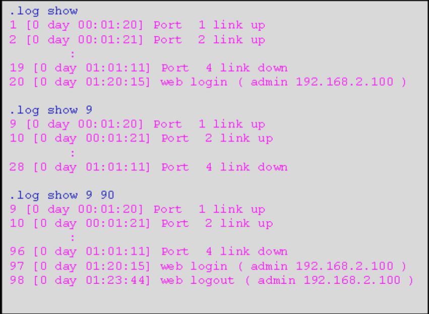
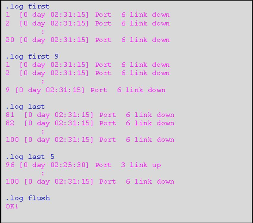
174 174


175 4.2.9 Load/Save Configuration Configuration command Parameter Description.config save In order to save configuration settings permanently, users need to save configuration first before resetting the Managed Industrial PoE Switch..config default Load Factory Settings Except Network Configuration will set all configurations of the Managed Industrial PoE Switch back to the factory default settings. However, IP and Gateway addresses will not restore to the factory default..config default-all Load Factory Settings will set all configurations of the Managed Industrial PoE Switch back to the factory default settings, including the IP and Gateway address. Example: Reboot Reboot command Parameter Description.reboot After any configuration changes, Reboot can make changes effective. Example: 175


176 5. Bluetooth App Management (Optional) Note: Bluetooth management is for Android only. In this chapter we are going to introduce Bluetooth App Management. Bluetooth App is an application for management service featuring graphical interface, giving well-organized system to make configuration via mobile devices. 5.1 Preparation Download CTS BT from Internet and install it. Launch CTS BT. The App will automatically search for available devices, or you can click scan on the upper right corner of screen for manual search. For initial use, keep the wireless device search for 1~2 minutes until designated device name appears. The format of default name on wireless device should be: <System Name_Last six digits of MAC > Any system name with check mark V indicates that the system name was paired and logged before. Choose the device you want to pair and click it. The communication is built once clicking a switch. To close the App, click Back Key on your mobile device to return to the Bluetooth Devices screen, click Back Key once again, a message of Leave Application will pop out. Choose Yes to quit the App. There are two formats shown on the screen for each switch. The upper one is system name with last six digits of Ethernet Interface MAC while the lower is MAC of Bluetooth. 176


177 5.2 Bluetooth App Login Bluetooth App After successfully connecting with a switch, you are automatically navigated login screen. Type both User Name and Password to login. Note: The default setting of username is admin while the password is not required Icon Introduction After a successful login, the screen appears as below System Information: Name the Managed Industrial PoE Switch, specify the location and check the current version of information. 177


178 2. User Authentication: Create and view the registered user list. 3. Network Management: Set up or view the IP address and related information about the Managed Industrial PoE Switch required for network management applications. 4. Port: Enable or disable port speed, flow control, etc. and show the status of traffic rates and events. 5. Config Management: Save current settings or load factory settings. 6. Event Log: This keeps a record of user login and logout timestamp information. 7. Reboot: Restart the switch. 8. Log out: Log out Bluetooth App. 9. Previous Icon: Back to the previous page System Information Click System Information icon and then the following screen shows up. 178

179 Company Name: Enter a company name up to 55 alphanumeric characters for this Managed Industrial PoE Switch. System Contact: Enter contact information up to 55 alphanumeric characters for this Managed Industrial PoE Switch. System Name: Enter a unique name up to 55 alphanumeric characters for this Managed Industrial PoE Switch. Use a descriptive name to identify the Managed Industrial PoE Switch in relation to your network, for example, Backbone 1. This name is mainly used for reference. System Location: Enter a brief description of the Managed Industrial PoE Switch location up to 55 alphanumeric characters. The location is for reference only. DHCP Vendor ID: Enter the user-defined vendor ID up to 55 alphanumeric characters. Please make sure you have an exact DHCP Vendor ID with the value specified in vendor-classes in your dhcp.conf file. For detailed information, see Appendix A. Host Name: View-only field that shows the product s host name. 1000M Port Number: The number of ports transmitting at the speed of 1000Mbps 100M Port Number: The number of ports transmitting at the speed of 100Mbps Model Name: View-only field that shows the product s model name. Boot up image: The first image used for boot up. Next Boot up image: The second image used for boot up. Serial Number: View-only field that shows the serial number of this switch. 179
180 Date Code: View-only field that shows the Managed Industrial PoE Switch firmware date code. M/B Version: View-only field that shows the main board version. Image 1 Firmware Version: The firmware version of the first image. Image 2 Firmware Version: The firmware version of the second image. Fiber 1 Type: View-only field that shows information about the slide-in or fixed fiber type. Fiber 2 Type*: View-only field that shows information about the slide-in or fixed fiber type. Up time: View-only field that shows how long the device has been powered on. Local Time: View-only field that shows the time of the location where the switch is. Power 1: View-only field that shows the power status of power 1. Power 2: View-only field that shows the power status of power 2. Click the OK button to apply the modifications. *Fiber 2 information for 2-fiber model only User Authentication To prevent any un-authorized operation, only registered users are allowed to operate the Managed Industrial PoE Switch. Users who want to operate the Managed Industrial PoE Switch need to register into the user s list first. To view or change current registered users, click User Authentication icon and then the following screen page shows up. 180

181 Click to add a new user account, then the following screen page appears. Note: The maximum user account number is three. Click to view and edit a registered user setting. Click to remove a registered user setting. 181

182 User Name: Specify the authorized user login name, up to 20 alphanumeric characters. State: Enable or disable the selected account. When being disabled, the account should be shown with slashes. Example: Password: Enter the desired user password, up to 20 alphanumeric characters. Retype Password: Enter the password again to confirm. Role: Select the preferred access level for this newly created account. Administrator: Full access right, including maintaining user account, system information, loading factory settings, etc.. Read & Write: Partial access right, unable to modify system information, user account, load factory settings and upgrade firmware. Read Only: Read only access right. Description: Enter a unique description up to 35 alphanumeric characters for this user. This is mainly for reference only. NOTE: If you forget the login password, the only way to gain access to the Web Management is to set the Managed Industrial PoE Switch back to the factory default setting by pressing the Reset button for 10 seconds 182

183 (The Reset button is located on the Upper Panel of the Managed Industrial PoE Switch.). When the Managed Industrial PoE Switch returns back to the default setting, you can login with the default login username and password (By default, no password is required. Leave the field empty and then press Login.) Click the OK button to apply the settings Network Management Click Network Configuration icon and then the following screen page appears. IP Network Current State: This shows the state network configuration at present. MAC Address: This view-only field shows the unique and permanent MAC address pre-assigned to the Managed Industrial PoE Switch. You cannot change the Managed Industrial PoE Switch s MAC address. IP Address: An Internet Protocol address (IP address) is a numerical label assigned to each device (e.g., computer, printer) participating in a computer network that uses the Internet Protocol for communication. Subnet Mask: It is the bitmask that when applied by a bitwise AND operation to any IP address in the network, yields the routing prefix. Gateway: This address is required when the Managed Industrial PoE Switch and the network management station are on different networks or subnets. The default value of this parameter is , which means no gateway exists and the network management station and Managed Industrial PoE Switch are on the same network. IP Network Information: This provides with editable field for configuration. 183

184 IPv4 Type: There are two configuration types that users can select from the pull-down menu; these are DHCP and Manual. When DHCP is selected and a DHCP server is also available on the network, the Managed Industrial PoE Switch will automatically get the IP address from the DHCP server. If Manual is selected, users need to specify the IP address, Subnet Mask and Gateway. NOTE: This Managed Industrial PoE Switch supports auto-provisioning function that enables DHCP clients to automatically download the latest firmware and configuration image from the server. For information about how to set up a DHCP server, please refer to APPENDIX A. IP Address: Enter the unique IP address for this Managed Industrial PoE Switch. You can use the default IP address or specify a new one when the situation of address duplication occurs or the address does not match up with your network. (The default factory setting is ) Subnet Mask: Specify the subnet mask. The default subnet mask values for the three Internet address classes are as follows: Class A: Class B: Class C: Gateway: Specify the IP address of a gateway or a router, which is responsible for the delivery of the IP packets sent by the Managed Industrial PoE Switch. Click the OK button to apply the settings Port Configuration Click the Port icon and then the following screen page appears. 184

185 Status: Shows the current status of each port. Configuration: You may set up each port of the switch here, including state, port type, speed, duplex, flow control and description. Traffic Rates Statistics: View the number of bytes received, frames received, bytes sent, frames sent, each port s analysis history. Traffic Rates Error: View the number of CRC errors, undersize frames, fragment frames etc. Traffic Events Statistics: View the number of bytes received, frames received, bytes sent, frames sent, each port s analysis history and clear each row s statistics. Traffic Events Error: View the number of CRC errors, undersize frames, fragment frames etc. and clear each row s statistics Status Link: The port connected with cable shows with check mark (link up) while disconnected with cable shows with cross mark (link down). 2. Media Type: This shows the media type (either Fiber or Copper) of the selected port. 3. Type: This shows the port type of either Auto-Negotiation or Manual mode. 4. Speed: The transmission speed (10Mbps/100Mbps/1000Mbps) of the port(s). 5. Duplex: The current operation Duplex mode (full or half duplex) of the port(s). 185

186 6. Flow Control: The current status of whether Flow Control function is enabled or disabled. When enabled, the letters of Flow Control with bracket will be shown. 7. State: The current status of port state. When being disabled, the port will be shown with slashes Configuration Media Type: This shows the media type (either Fiber or Copper) of the selected port. 2. Type: This shows the port type of either Auto-Negotiation or Manual mode. 3. Speed: The transmission speed (10Mbps/100Mbps/1000Mbps) of the port(s). 4. Duplex: The current operation Duplex mode (full or half duplex) of the port(s). 5. Flow Control: The current status of whether Flow Control function is enabled or disabled. When enabled, the letters of Flow Control with bracket will be shown. 6. Description: This is the remark of a port. To edit configuration of a port, click pencil mark at the right side of the screen. If you need to edit either multiple copper or fiber ports, check the box at the left side and click the pencil mark on the upper left of the screen. Then the following screen will appear. 186
 of the selected port. This field is open to select only when ports of the device have two media type.")
187 Note: Ports with different media type cannot be edited at the same time. State: Enable or disable the current port state. Media Type: This shows the media type (either Fiber or Copper) of the selected port. This field is open to select only when ports of the device have two media type. Type: Select Auto-Negotiation or Manual mode as the port type. Speed: When you select Manual port type, you can further specify the transmission speed (10Mbps/100Mbps/1000Mbps) of the port(s). Duplex: When you select Manual port type, you can further specify the current operation Duplex mode (full or half duplex) of the port(s). Flow Control: Enable or disable Flow Control function. Description: You may type any remark or comment on the box. Click the OK button to apply the settings Traffic Rates The rate mode of port counters will be re-calculated when that counter is reset or cleared Traffic Rates Statistics Click Statistics under Traffic Rates of Port Configuration, the following screen for viewing appears. 187


188 You may click up arrow to expand or down arrow to collapse. Rx Frames: Total frames received from each port. Rx Bytes: Total bytes received from each port. Rx Utilization: The ratio of each port s receiving traffic to current port s total bandwidth. Rx MC: Good multicast frames received. Rx BC: Good broadcast frames received. Tx Frames: The total frames sent from current port. Tx Bytes: The total bytes sent from current port. Tx Utilization: The ratio of each port s sending traffic to current port s total bandwidth. Tx MC: Good multicast packets sent. Tx BC: Good broadcast packets sent. Rx 64: 64 bytes frames received. Rx : bytes frames received. Rx : bytes frames received. Rx : bytes frames received. 188
189 Rx : bytes frames received. Rx : bytes frames received. Rx > 1518: Bytes frames greater than 1518 received Traffic Rates Error Click Error under Traffic Rates of Port Configuration, the following screen for viewing appears. RX Error: The number of packets received with a bad FCS with an integral number of bytes. RX Undersize: Undersize frames received. RX Fragments: Fragment frames received. TX Collisions: Total frames collision detected Traffic Events The event mode of port counters will be re-calculated when that counter is reset or cleared Traffic Event Statistics View the number of bytes received, frames received, bytes sent, frames sent, each port s analysis history and clear each row s statistics. 189

190 You may click up arrow to expand or down arrow to collapse. Rx Frames: Total frames received from each port. Rx Bytes: Total bytes received from each port. Rx MC: Good multicast frames received. Rx BC: Good broadcast frames received. Tx Frames: The total frames sent from current port. Tx Bytes: The total bytes sent from current port. Tx MC: Good multicast packets sent. Tx BC: Good broadcast packets sent. Rx 64: 64 bytes frames received. Rx : bytes frames received. Rx : bytes frames received. Rx : bytes frames received. Rx : bytes frames received. Rx : bytes frames received. 190

191 Rx>1518: Bytes frames greater than 1518 received. Clear All: Click Clear All to clear all ports statistics Traffic Event Error Click Error under Traffic Event of Port Configuration, the following screen for viewing appears. RX Error: The number of packets received with a bad FCS with an integral number of bytes. RX Undersize: Undersize frames received. RX Fragments: Fragment frames received. TX Collisions: Total frames collision detected. Clear All: Click Clear All to clear all ports statistics Config Management This section helps how to save current configuration and load factory settings. Click Config the following screen appears. and 191

192 Save Config: In order to save configuration settings permanently, users need to save configuration first before resetting the Managed Industrial PoE Switch. Click the Save Config to save changes. Load All Factory Settings: It will set all configurations of the Managed Industrial PoE Switch back to the factory default settings, including the IP and Gateway address. This function is useful when network administrators would like to re-configure the system. A system reset is required to make all changes effective after Load Factory Setting. Click the Load All Factory Settings to restore the Managed Industrial PoE Switch back to the defaults. Load All Factory Settings(Except Network Configuration): It will set all configurations of the Managed Industrial PoE Switch back to the factory default settings. However, IP and Gateway addresses will not restore to the factory default. Load Factory Settings Except Network Configuration is very useful when network administrators need to re-configure the system REMOTELY because conventional Factory Reset will bring network settings back to default and lose all remote network connections. Click the Load All Factory Settings(Except Network Configuration) to restore the Managed Industrial PoE Switch back to the defaults excluding network configurations Event Log Event log keeps a record of user login and logout timestamp information. Select Event Log from the menu and then the following screen page appears. 192


193 The Event Log table stores the latest 500 logs in the Managed Industrial PoE Switch. Three options are available: Display from, Display First and Display Last. Display from: Show event logs starting from the designated index number box while size box represents the size of record to be shown starting from index number. The max size of data can be shown is 100. Click Clear All to clear all Event Log records. 193

194 Size Box Example: Index Number Box Display First: Show event logs starting from the beginning. The max size of data can be shown is 100. Click Clear All to clear all Event Log records. Example: 194
195 Display Last: Show event logs starting from the end. The max size of data can be shown is 100. Click Clear All to clear all Event Log records. Example: Reboot After any configuration changes, Reboot can make changes effective. Select Reboot from the main menu and then the following screen page appears. 195

196 Click the Yes button to restart the Managed Industrial PoE Switch. 196

197 APPENDIX A: DHCP Auto-Provisioning Setup Networking devices, such as switches or gateways, with DHCP Auto-provisioning function allow you to automatically upgrade firmware and configuration at startup process. Before setting up DHCP Server for auto-upgrade of firmware and configuration, please make sure the Managed Industrial PoE Switch that you purchased supports DHCP Auto-provisioning. Setup procedures and auto-provisioning process are described below for your reference. A. Setup Procedures Follow the steps below to set up Auto Provisioning server, modify dhcpd.conf file and generate a copy of configuration file. Step 1. Set Up Environment DHCP Auto-provisioning-enabled products that you purchased support the DHCP option 60 to work as a DHCP client. To make auto-provisioning function work properly, you need to prepare ISC DHCP server, File server (TFTP or FTP) and the switching device. See below for a possible network topology example. ISC DHCP Server TFTP Server Switch Switch Topology Example 197


198 Step 2. Set Up Auto Provision Server Update DHCP client Linux Fedora 12 supports yum function by default. First of all, update DHCP client function by issuing yum install dhclient command. Install DHCP server Issue yum install dhcp command to install DHCP server. 198


199 Copy dhcpd.conf to /etc/dhcp/ directory Copy dhcpd.conf file provided by the vendor to /etc/dhcp/ directory. Please note that each vendor has its own way to define auto-provisioning. Make sure to use the file provided by the vendor. Enable and run DHCP service Choose dhcpd. 2. Enable DHCP service. 3. Start running DHCP service. NOTE: DHCP service can also be enabled using CLI. Issue dhcpd command to enable DHCP service. 199


200 Step 3. Modify dhcpd.conf File Open dhcpd.conf file in /etc/dhcp/ directory Double-click dhcpd.conf placed in /etc/dhcp/ directory to open it. 200
201 Modify dhcpd.conf file The following marked areas in dhcpd.conf file can be modified with values that work with your networking environment. 1. Define DHCP default and maximum lease time in seconds. Default lease time: If a client does not request a specific IP lease time, the server will assign a default lease time value. Maximum lease time: This is the maximum length of time that the server will lease for. 2. Define subnet, subnet mask, IP range, broadcast address, router address and DNS server address. 3. Map a host s MAC address to a fixed IP address. 4. Map a host s MAC address to a fixed IP address. Use the same format to create multiple MAC-to- IP address bindings. 201
202 5. This value is configurable and can be defined by users. 6. Specify the protocol used (Protocol 1: FTP; Protocol 0: TFTP). 7. Specify the FTP or TFTP IP address. 8. Login TFTP server anonymously (TFTP does not require a login name and password). 9. Specify FTP Server login name and password. 10. Specify the product model name. 11. Specify the firmware filename. 12. Specify the MD5 for firmware image. 13. Specify the configuration filename. 14. Specify the MD5 for configuration file. NOTE 1: The text beginning with a pound sign (#) will be ignored by the DHCP server. For example, in the figure shown above, firmware-file-name HS-0600-provision_2.bin and firmware-md5 (line 5 & 6 from the bottom) will be ignored. If you want DHCP server to process these two lines, remove pound signs in the initial of each line. NOTE 2: You can use either free software program or Linux default md5sum function to get MD5 checksum for firmware image and configuration file. 202


203 Restart DHCP service 203
204 Every time you modify dhcpd.conf file, DHCP service must be restarted. Issue killall dhcpd command to disable DHCP service and then issue dhcpd command to enable DHCP service. Step 4. Backup a Configuration File Before preparing a configuration file in TFTP/FTP Server, make sure the device generating the configuration file is set to Get IP address from DHCP assignment. DHCP Auto-provisioning is running under DHCP mode, so if the configuration file is uploaded by the network type other than DHCP mode, the downloaded configuration file has no chance to be equal to DHCP when provisioning, and it results in MD5 never matching and causes the device to reboot endlessly. In order to have your Managed Industrial PoE Switch retrieve the correct configuration image in TFTP/FTP Server, please make sure the filename of your configuration file is defined exactly the same as the one specified in dhcpd.conf. For example, if the configuration image s filename specified in dhcpd.conf is metafile, the configuration image filename should be named to metafile as well. Step 5. Place a Copy of Firmware and Configuration File in TFTP/FTP The TFTP/FTP File server should include the following items: 1. Firmware image (This file is provided by the vendor.) 2. Configuration file (This file is generally created by users.) 3. User account for your device (For FTP server only.) 204

205 B. Auto-Provisioning Process This switching device is setting-free (through auto-upgrade and configuration) and its upgrade procedures are as follows: 1. ISC DHCP server will recognize the device when it receives an IP address request sent by the device, and it will tell the device how to get a new firmware or configuration. 2. The device will compare the firmware and configuration MD5 code form of DHCP option every time it communicates with DHCP server. 3. If MD5 code is different, the device will then upgrade the firmware or configuration. However, it will not be activated immediately. 4. If the Urgency Bit is set, the device will be reset to activate the new firmware or configuration immediately. 5. The device will retry for 3 times if the file is incorrect, and then it gives up until getting another DHCP ACK packet again. 205
HES-3106 SERIES 6 PORTS 10/100/1000BASE-T ETHERNET MANAGED SWITCH
 HES-3106 SERIES 6 PORTS 10/100/1000BASE-T ETHERNET MANAGED SWITCH 5 PORTS 10/100/1000BASE-T ETHERNET MANAGED SWITCH WITH 1 PORT 1000BASE-X or 100/1000BASE-X UPLINK 5 PORTS 10/100/1000BASE-T ETHERNET MANAGED
EPS PoE+ ports 10/100/1000Mbps RJ combo uplink ports (10/100/1000 Mbps RJ-45 and 100/1000Mbps SFP slot) Managed Ethernet PoE Switch
 Managed Ethernet PoE Switch") EPS-3128 24 PoE+ ports 10/100/1000Mbps RJ-45 + 4 combo uplink ports (10/100/1000 Mbps RJ-45 and 100/1000Mbps SFP slot) Managed Ethernet PoE Switch Network Management User s Manual Version 0.90 1 Revision
EPS-3128 24 PoE+ ports 10/100/1000Mbps RJ-45 + 4 combo uplink ports (10/100/1000 Mbps RJ-45 and 100/1000Mbps SFP slot) Managed Ethernet PoE Switch Network Management User s Manual Version 0.90 1 Revision
HES-3109SSFP-DR. 8 ports 10/100/1000Mbps RJ port 100/1000Mbps SFP slot Uplink Managed Ethernet CPE Switch. Network Management.
 HES-3109SSFP-DR 8 ports 10/100/1000Mbps RJ45 + 1 port 100/1000Mbps SFP slot Uplink Managed Ethernet CPE Switch Network Management User s Manual Version 0.94 1 Revision History Version F/W Date Description
HES-3106SFP-F2 6-port L2+ Managed Gigabit Fiber Switch Network Management User s Manual Version 1.0
 HES-3106SFP-F2 6-port L2+ Managed Gigabit Fiber Switch Network Management User s Manual Version 1.0 1 Revision History Version F/W Date Description 1.0 0.99.0A 2018/11/09 First release 2 Trademarks CTS
icpe Gateway Controller
 icpe Gateway Controller Network Management User s Manual Version 0.90 1 Trademarks Contents are subject to revision without prior notice. All other trademarks remain the properties of their owners. Copyright
HET-2106 SERIES. 5 ports 10/100Mbps RJ port 100Mbps fiber optics uplink Managed Ethernet CPE Switch. Network Management.
 HET-2106 SERIES 5 ports 10/100Mbps RJ-45 + 1 port 100Mbps fiber optics uplink Managed Ethernet CPE Switch Network Management User s Manual Version 0.97 1 Trademarks CTS is a registered trademark of Connection
FRG-3105 Series Residential Gateway
 FRG-3105 Series Residential Gateway Network Management User s Manual Version 0.90 1 Trademarks Contents are subject to revision without prior notice. All other trademarks remain the property of their respective
SD24GS. 24-Port Web Smart Gigabit Ethernet Switch. User s Manual
 SD24GS 24-Port Web Smart Gigabit Ethernet Switch User s Manual FCC Warning This equipment has been tested and found to comply with the limits for a Class A digital device, pursuant to Part 15 of the FCC
SWP-0208G, 8+2SFP. 8-Port Gigabit Web Smart Switch. User s Manual
 SWP-0208G 1 SWP-0208G, 8+2SFP 8-Port Gigabit Web Smart Switch User s Manual Version: 3.4 April 1, 2008 2 TABLE OF CONTENT 1.0 INTRODUCTION...4 1.1 MAIN FEATURES...4 1.2 START TO MANAGE THIS SWITCH...6
HES-3106-PLUS SERIES
 HES-3106-PLUS SERIES 5 PORTS 10/100/1000BASE-T ETHERNET MANAGED SWITCH WITH 1 PORT 1000BASE-X or 100/1000BASE-X UPLINK User s Guide Version 0.92 Trademarks CTS is a registered trademark of Connection Technology
IPS-3110 Managed Industrial PoE Gigabit Ethernet Switch
 IPS-3110 Managed Industrial PoE Gigabit Ethernet Switch User s Guide Version 0.90 Trademarks Contents are subject to revision without prior notice. All other trademarks remain the property of their respective
FWR Series Residential Gateway
 FWR5-3105 Series Residential Gateway Network Management User s Manual Version 0.92 1 Trademarks Contents are subject to revision without prior notice. All other trademarks remain the property of their
HES-3109 SERIES 9 PORTS 10/100/1000BASE-T MANAGEMENT ETHERNET SWITCH
 HES-3109 SERIES 9 PORTS 10/100/1000BASE-T MANAGEMENT ETHERNET SWITCH 8 PORTS 10/100/1000BASE-T MANAGEMENT ETHERNET SWITCH WITH 1 PORT 1000BASE-X UPLINK OR 1 PORT 100/1000BASE-X UPLINK 8 PORTS 10/100/1000BASE-T
Network Management. User s Manual. Version: 0.90
 MCT-RACK-12-MGM 12 SLOTS COMPACT MEDIA CONVERTER CENTER Network Management User s Manual Version: 0.90. Trademarks CTS is a registered trademark of Connection Technology Systems Inc.. Contents are subject
FWRIII-2105 SERIES. 4 ports 10/100Mbps RJ-45; built-in IEEE802.11n WiFi and 1 port 100Mbps SFP slot uplink Residential Gateway. Residential Gateway
 FWRIII-2105 SERIES 4 ports 10/100Mbps RJ-45; built-in IEEE802.11n WiFi and 1 port 100Mbps SFP slot uplink Residential Gateway 4 ports 10/100Mbps RJ-45; built-in IEEE802.11n WiFi and 1 port 100Mbps SFP
Management Software AT-S79. User s Guide. For use with the AT-GS950/16 and AT-GS950/24 Smart Switches. Version Rev.
 Management Software AT-S79 User s Guide For use with the AT-GS950/16 and AT-GS950/24 Smart Switches Version 1.0.0 613-000207 Rev. A Copyright 2005 Allied Telesyn, Inc. All rights reserved. No part of this
Management Software AT-S101. User s Guide. For use with the AT-GS950/8POE Gigabit Ethernet WebSmart Switch. Version Rev.
 Management Software AT-S101 User s Guide For use with the AT-GS950/8POE Gigabit Ethernet WebSmart Switch Version 1.0.0 613-000985 Rev. A Copyright 2008 Allied Telesis, Inc. All rights reserved. No part
IN-16POEGWM. User Manual. 16 Port Gigabit Ethernet + 4 Combo Gigabit SFP PoE Web Smart Switch
 IN-16POEGWM User Manual 16 Port Gigabit Ethernet + 4 Combo Gigabit SFP PoE Web Smart Switch FCC Warning This Equipment has been tested and found to comply with the limits for a Class-A digital device,
Peplink SD Switch User Manual. Published on October 25th, 2018
 Peplink SD Switch User Manual Published on October 25th, 2018 1 Table of Contents Switch Layout 4 Specifications 5 Hardware Overview 6 Quick Start Functions 7 Reset Switch 7 Connect Ethernet 7 Connect
SW24MGSFP 10/100/1000 Mbps + 2 Gb SFP Web Smart Ethernet Switch User Manual Version 1.0 (January 2011)
") SW24MGSFP 10/100/1000 Mbps + 2 Gb SFP Web Smart Ethernet Switch User Manual Version 1.0 (January 2011) TABLE OF CONTENTS PACKING LIST... 1 PRODUCT OVERVIEW... 3 FEATURES... 3 HARDWARE INSTALLATION... 4
SW24MGSFP 10/100/1000 Mbps + 2 Gb SFP Web Smart Ethernet Switch User Manual Version 1.0 (January 2011) TABLE OF CONTENTS PACKING LIST... 1 PRODUCT OVERVIEW... 3 FEATURES... 3 HARDWARE INSTALLATION... 4
IEC /IEEE 1613 Lite L3 Hardened Managed 24-port Gigabit SFP. 10GbE Connectivity Four 10G SFP+ for connecting the switch to the core network
 IEC 61850-3/IEEE 1613 Lite L3 Hardened Managed 24-port Gigabit and 4-port 1G/10G SFP+ Ethernet Switch NEMATS2 IEC 61850-3 IEEE 1613 SFP Option Overview EtherWAN s provides a Hardened Full-Gigabit Managed
ProSAFE 8-Port and 16-Port 10-Gigabit Ethernet Web Managed Switch Models XS708Ev2 and XS716E User Manual
 ProSAFE 8-Port and 16-Port 10-Gigabit Ethernet Web Managed Switch Models XS708Ev2 and XS716E User Manual March 2017 202-11656-03 350 East Plumeria Drive San Jose, CA 95134 USA Support Thank you for purchasing
EX Lite L3 Hardened Managed 24-port Gigabit and 4-port 1G/10G SFP+ Ethernet Switch SFP
 Lite L3 Hardened Managed 24-port Gigabit and 4-port 1G/10G SFP+ Ethernet Switch Reduced depth of 254mm NEMATS2 SFP Option Overview EtherWAN s Series provides a Hardened Full-Gigabit Managed 28-port switching
16-SLOT IN-BAND MANAGEMENT CHASSIS
 FCM-CHS2-XX 16-SLOT IN-BAND MANAGEMENT CHASSIS Network Management Manual Version 2.2 1 FCC Warning This equipment has been tested and found to comply with the limits for a Class A digital device, pursuant
ProSAFE 8-Port 10-Gigabit Web Managed Switch Model XS708Ev2 User Manual
 ProSAFE 8-Port 10-Gigabit Web Managed Switch Model XS708Ev2 User Manual April 2016 202-11656-01 350 East Plumeria Drive San Jose, CA 95134 USA Support Thank you for purchasing this NETGEAR product. You
Security SSID Selection: Broadcast SSID:
 69 Security SSID Selection: Broadcast SSID: WMM: Encryption: Select the SSID that the security settings will apply to. If Disabled, then the device will not be broadcasting the SSID. Therefore it will
Product features. Applications
 Applications Layer 2+ VLAN static routing application The managed switch features a built-in, robust IPv4/IPv6 Layer 3 traffic static routing protocol to ensure reliable routing between VLANs and network
User Handbook. Switch Series. Default Login Details. Version 1.0 Edition
 User Handbook Switch Series Zyxel GS1920 / GS2210 / XGS2210 / GS3700 / XGS3700 / XGS4600 / XS1920 / XS3700 Default Login Details LAN IP Address https://192.168.1.1 User Name admin Password 1234 Version
JSH2402GBM. Introduction. Main Features Combo Port Mixed Giga Ethernet SNMP Switch. Picture for reference
 JSH2402GBM 24+2 Combo Port Mixed Giga Ethernet SNMP Switch Introduction Picture for reference The 24+2 Combo Port Mixed Giga Ethernet SNMP Switch is ideal for medium to large Internet bar or enterprise,
Nighthawk S8000 Gaming & Streaming Advanced 8-Port Gigabit Ethernet Switch User Manual
 Nighthawk S8000 Gaming & Streaming Advanced 8-Port Gigabit Ethernet Switch User Manual Model GS808E March 2017 202-11732-01 350 E. Plumeria Drive San Jose, CA 95134 USA Support Thank you for purchasing
48-Port 10/100Mbps + 4 Gigabit TP / 2 SFP Managed Switch
 High-Density / Cost-effective / Powerful class Fast Ethernet solution for SMB / Enterprise Network The PLANET is 48-Port 10/100Mbps + 4 Gigabit TP / 2 SFP Managed Switch with advanced Web-based management
Command Guide of WGSW-28040
 1 Command Guide of WGSW-28040 Contents Command Guide of WGSW-28040 Chapter 1 COMMAND LINE INTERFACE... 12 1.1 Accessing the CLI... 12 1.2 Command Line Modes... 12 1.3 Cammand Help... 13 1.4 Command Line
8-port mk2 user s guide v port mk2
 8-port mk2 1 CONTENT The 8-port mk2... 4 Connection example... 5 User Login... 6 Switch Status... 7 System information... 7 Logging message... 7 Port counters... 8 Aggregation state... 8 LLDP statistics...
RANGER SERIES. 150Mbps Wireless Green Broadband Router DG-BR4000NG. 150 Mbps V
 RANGER SERIES 150Mbps Wireless Green Broadband Router DG-BR4000NG N 150 Mbps V1.2 2011-12-15 FCC warning: This equipment has been tested and found to comply with the limits for a class B digital device,
IN-16POEWM. User Manual. 16 Port Fast Ethernet PoE Web Smart Switch. Version V100817
 IN-16POEWM User Manual 16 Port Fast Ethernet PoE Web Smart Switch Version V100817 FCC Warning This Equipment has been tested and found to comply with the limits for a Class-A digital device, pursuant to
FRG-3105 Series Residential Gateway
 FRG-3105 Series Residential Gateway User s Guide Version 0.90 Revision History Version Date Description 0.90 20170605 First Release 2 Trademarks Contents are subject to revision without prior notice. All
VERTICAL HORIZON VH-2402S FAST ETHERNET SWITCH MANAGEMENT GUIDE
 VERTICAL HORIZON VH-2402S FAST ETHERNET SWITCH MANAGEMENT GUIDE 9033645-01 Notice Only qualified personnel should perform installation procedures. NOTICE Enterasys Networks reserves the right to make
8-Port 10/100/1000 Gigabit Switch. User Guide. with WebView WIRED SRW2008/SRW2008P/SRW2008MP. Model No.
 8-Port 10/100/1000 Gigabit Switch with WebView WIRED User Guide Model No. SRW2008/SRW2008P/SRW2008MP Copyright and Trademarks Specifications are subject to change without notice. Linksys is a registered
FCN-3112 Series. 10/100/1000TX to 1000SX SNMP Managed Media Converter. Version 1.0 User Manual
 FCN-3112 Series 10/100/1000TX to 1000SX SNMP Managed Media Converter Version 1.0 User Manual Copyright 2018 Antaira Technologies, LLC. All Rights Reserved This document contains information, which is protected
Overview. Spotlight. Hardened Managed 4 to 10-port 10/100BASE (8 x PoE) and 2-port Gigabit Ethernet Switch SFP. 60W PoE
 and 2-port Gigabit Ethernet Switch SFP. 60W PoE") Hardened Managed 4 to 10-port 10/100BASE (8 x PoE) and 2-port Gigabit Ethernet Switch UL 61010 NEMATS2 SFP Option 60W PoE Overview EtherWAN's provides a hardened 12-port switching platform supporting 60W
Hardened Managed 4 to 10-port 10/100BASE (8 x PoE) and 2-port Gigabit Ethernet Switch UL 61010 NEMATS2 SFP Option 60W PoE Overview EtherWAN's provides a hardened 12-port switching platform supporting 60W
Peplink SD Switch User Manual
 Peplink SD Switch User Manual Peplink Products: Peplink SD Switch 8-ports/24-ports/48-ports Peplink SD Switch Firmware 1.2.0 Published on December 10, 2018 Copyright & Trademarks Copyright & trademark
LevelOne GES GE with 1 Combo SFP Web Smart Switch User Manual
 LevelOne GES-0852 8 GE with 1 Combo SFP Web Smart Switch User Manual Version 1.0-1109 1 FCC Certifications This Equipment has been tested and found to comply with the limits for a Class A digital device,
Wireless 11n Smart Repeater AP (1T1R)
") (1T1R) 2014 Table of Contents 1. Introduction...3 1.1 Package contents... 3 1.2 Product Features... 3 1.3 Front Panel Description... 4 1.4 Rear Panel Description... 5 2. Installation...6 2.1 Hardware Installation...
(1T1R) 2014 Table of Contents 1. Introduction...3 1.1 Package contents... 3 1.2 Product Features... 3 1.3 Front Panel Description... 4 1.4 Rear Panel Description... 5 2. Installation...6 2.1 Hardware Installation...
SFTOS Configuration Guide
 SFTOS Configuration Guide Version 2.5.3.0 August 2008 Edition Copyright 2008 Force10 Networks All rights reserved. Printed in the USA. August 2008. Force10 Networks reserves the right to change, modify,
NGSME16T2H. (16-port 10/100/1000Base-T + 2 Gigabit SFP L2+ Management PoE Switch)
") NGSME16T2H (16-port 10/100/1000Base-T + 2 Gigabit SFP L2+ Management PoE Switch) More information: WWW.NIVEOPROFESSIONAL.COM INFO@NIVEOPROFESSIONAL.COM Product Specification Introduction The NGSM16ET2H
NGSME16T2H (16-port 10/100/1000Base-T + 2 Gigabit SFP L2+ Management PoE Switch) More information: WWW.NIVEOPROFESSIONAL.COM INFO@NIVEOPROFESSIONAL.COM Product Specification Introduction The NGSM16ET2H
T PCT. Smart PoE Switch REV
 T1500-28PCT Smart PoE Switch REV1.0.0 1910011255 COPYRIGHT & TRADEMARKS Specifications are subject to change without notice. is a registered trademark of TP-LINK TECHNOLOGIES CO., LTD. Other brands and
FWR-2105-WF-G SERIES FWR-2105-WF-N SERIES FWR-2105-WF-G-RF FWR-2105-WF-N-RF
 FWR-2105-WF-G SERIES 4 ports 10/100Mbps RJ-45, built-in IEEE 802.11b/g WiFi and 1 port 100Mbps fiber optics uplink Triple Play Gateway FWR-2105-WF-N SERIES 4 ports 10/100Mbps RJ-45, built-in IEEE 802.11
Gigabit Managed Ethernet Switch
 LGB1110A LGB1126A-R2 Product Data Sheet Gigabit Managed Ethernet Switch Features Overview LGB1110A The Gigabit Managed Ethernet Switches offer L2 features plus advanced L3 features such as Static Route
AMG9082W-HP260-C User s Manual
 8 x 10/100 PoE+ 802.3at w/ 2 Gigabit Combo Ports RJ45/SFP Fast Ethernet Switch AMG9082W-HP260-C User s Manual www.amgsystems.com FCC Warning This Equipment has been tested and found to comply with the
LevelOne. User Manual. WAP Mbps PoE Wireless AP V3.0.0
 LevelOne WAP-0005 108Mbps PoE Wireless AP User Manual V3.0.0 i TABLE OF CONTENTS CHAPTER 1 INTRODUCTION... 1 FIGURE 1: WIRELESS ACCESS POINT... 1 FEATURES OF YOUR WIRELESS ACCESS POINT... 1 Security Features...
PSGS-2610F L2+ Managed GbE PoE Switch
 PSGS-2610F L2+ Managed GbE PoE Switch Overview PSGS-2610F L2+ Managed PoE+ Switch is a next-generation Ethernet Switch offering full suite of L2 features, better PoE functionality and usability, including
FOS-3114 Series 14-port L2+ Managed Gigabit Fiber Switch User s Guide
 FOS-3114 Series 14-port L2+ Managed Gigabit Fiber Switch User s Guide Version: 1.1 Revision History Version Date Changes 1.0 12/21/2017 First release 1.1 02/27/2018 Add the new feature FCC Warning This
NGSME48T2H. (48-Port 10/100/1000Base-T Gigabit Combo TP/SFP Layer 2+ Full Management High Power PoE Switch)
") NGSME48T2H (48-Port 10/100/1000Base-T+ 2 10-Gigabit Combo TP/SFP Layer 2+ Full Management High Power PoE Switch) * 48-Port PoE Gigabit Copper + 2-port 10-Gigabit ComboTP/ SFP+ * 802.3az Energy Efficient
NGSME48T2H (48-Port 10/100/1000Base-T+ 2 10-Gigabit Combo TP/SFP Layer 2+ Full Management High Power PoE Switch) * 48-Port PoE Gigabit Copper + 2-port 10-Gigabit ComboTP/ SFP+ * 802.3az Energy Efficient
MR2324-4C. 24-Port Intelligent Gigabit Ethernet Switch. Management Guide
 MR2324-4C 24-Port Intelligent Gigabit Ethernet Switch Management Guide Management Guide Intelligent Gigabit Ethernet Switch with 24 10/100/1000BASE-T (RJ-45) Ports, and 4 Combination RJ-45/SFP Ports E082004-R01
8-Port 10/100Mbps + 2G TP / SFP Combo Managed Switch
 8-Port 10/100Mbps + 2G TP / SFP Combo Managed Switch Full-Functioned / Robust Layer2 Features Layer 2 / Layer 4 Managed Switch for Enterprise and Campus Networking The PLANET is an 8-Port 10/100Mbps Fast
TL-SL2210/TL-SL2218/TL-SL2428/TL-SL2452. Smart Switch REV
 TL-SL2210/TL-SL2218/TL-SL2428/TL-SL2452 Smart Switch REV1.2.1 1910011603 COPYRIGHT & TRADEMARKS Specifications are subject to change without notice. is a registered trademark of TP-LINK TECHNOLOGIES CO.,
AC1200M/MS. User Manual
 AC1200M/MS User Manual Table of Contents User Manual... 1 1 Preface... 1 2 LED Indicators and Connectors... 1 2.1 LED Indicators... 1 2.2 Hardware Installation... 2 3 Voice Prompt (AC1200MS)... 2 4 User
Spotlight Versatile Connectivity Provides 16-port 10/100BASE-TX plus 2-port Gigabit-SX/LX/BX combo
 Series Hardened Managed 16-port 10/100BASE with 2-port Gigabit combo Ethernet Switch NEMA TS2 UL61010 ISA.12.12.01 Overview EtherWAN s Series provides a Hardened Fully Managed 18-port switching platform
Managed Ethernet Switch User s Manual
 Managed Ethernet Switch User s Manual Information Coding: UM00D908 Version: V1.1 Product version: all Product Name: Managed Industrial Ethernet Switches on DIN Rail and Rack. Applicable to: Technical Support
TL-SG2216/TL-SG2424/TL-SG2424P/TL-SG2452. Gigabit Smart Switch REV
 TL-SG2216/TL-SG2424/TL-SG2424P/TL-SG2452 Gigabit Smart Switch REV2.0.0 1910011094 COPYRIGHT & TRADEMARKS Specifications are subject to change without notice. is a registered trademark of TP-LINK TECHNOLOGIES
IEC /IEEE1613 Managed 24-port 10/100BASE and 4-port Gigabit Ethernet Switch with SFP options
 Industrial Managed Ethernet Switches IEC61850-3/IEEE1613 Managed 24-port 10/100BASE and 4-port Gigabit Ethernet Switch with SFP options IEC 61850-3 Overview EtherWAN s provides an Industrial Fully Managed
Lite L3 Hardened Managed 16-port (8 x PoE) Gigabit Ethernet Switch. 8 X PoE provides 60 watt Ultra PoE ports Power Budget: 240W. 60W PoE.
 Gigabit Ethernet Switch. 8 X PoE provides 60 watt Ultra PoE ports Power Budget: 240W. 60W PoE.") Lite L3 Hardened Managed 16-port (8 x ) Gigabit Ethernet Switch 8 X provides 60 watt Ultra ports Power Budget: 240W 15W 60W SFP Option Overview EtherWAN's is a hardened DIN-rail mounted 16-port Gigabit
Lite L3 Hardened Managed 16-port (8 x ) Gigabit Ethernet Switch 8 X provides 60 watt Ultra ports Power Budget: 240W 15W 60W SFP Option Overview EtherWAN's is a hardened DIN-rail mounted 16-port Gigabit
L Port 10/100/1000T PoE + 2-Port Gigabit SFP + Managed Switch
 L2 + 24-Port 10/100/1000T PoE + 2-Port Gigabit SFP + Managed Switch PS-B8266VF series are high performance and cost efficiency 802.3af/at PoE Smart Switch. It comes with 24 dedicated 10/100/1000Mbps PSE
WebWise. 16/24 Port Gigabit Ethernet Switch. User`s Manual
 WebWise 16/24 Port Gigabit Ethernet Switch User`s Manual Nexxt Solutions Copyright Statement Nexxt Solutions is a registered trademark. Other trademarks or brand names contained herein are the trademarks
Figure 7-1 Unicast Static FDB window
 7. Layer 2 Features FDB VLAN Spanning Tree Loopback Detection Link Aggregation L2 Multicast Control LLDP FDB Static FDB Unicast Static FDB This window is used to view and configure the static unicast forwarding
48-Port Gigabit with 4 Shared SFP Managed Switch
 48-Port Gigabit with 4 Shared SFP Managed Switch High-Density / Cost-effective / Telecom class Gigabit solution for Enterprise backbone and Data Center Networking The PLANET is a Layer 2 / Layer 4 full
Managed Gigabit PoE Switch PS2460GM
 Managed Gigabit PoE Switch PS2460GM Description PS2460GM Enterprise Gigabit Ethernet switch with management function is designed to meet rigorous mission critical applications, such as factory automation,
48-Port 10/100/1000BASE-T + 4-Port 100/1000BASE-X SFP Gigabit Managed Switch GS T4S
 48-Port 10/100/1000BASE-T + 4-Port 100/1000BASE-X SFP Gigabit Managed Switch GS-4210-48T4S Outlines Product Overview Product Benefits Applications Appendix Product Features 2 / 42 Product Overview Layer
Hardened Managed 10-port 10/100BASE (8 x PoE) and 2-port Gigabit Ethernet Switch SFP
 and 2-port Gigabit Ethernet Switch SFP") Hardened Managed 10-port 10/100BASE (8 x PoE) and 2-port Gigabit Ethernet Switch UL508 SFP Option 15W PoE 30W PoE Overview EtherWAN's provides a hardened 12-port switching platform supporting IEEE802.3at
Hardened Managed 10-port 10/100BASE (8 x PoE) and 2-port Gigabit Ethernet Switch UL508 SFP Option 15W PoE 30W PoE Overview EtherWAN's provides a hardened 12-port switching platform supporting IEEE802.3at
User Manual ES-5808PHG. Gigabit 8-Port 802.3at PoE Web Smart Switch
 User Manual ES-5808PHG Gigabit 8-Port 802.3at PoE Web Smart Switch Content Content I Introduction..3 Product Overview.3 Web Management Feature.3 Specification..4 Mechanical...4 Performance...5 Package
NGSME24T2H-AV. (24-Rear Port 10/100/1000Base-T PoE + 2 Gigabit SFP Layer 2+ Management Current Sharing PoE+ Switch)
") NGSME24T2H-AV (24-Rear Port 10/100/1000Base-T PoE + 2 Gigabit SFP Layer 2+ Management Current Sharing PoE+ Switch) More information: WWW.NIVEOPROFESSIONAL.COM INFO@NIVEOPROFESSIONAL.COM Product Specification
NGSME24T2H-AV (24-Rear Port 10/100/1000Base-T PoE + 2 Gigabit SFP Layer 2+ Management Current Sharing PoE+ Switch) More information: WWW.NIVEOPROFESSIONAL.COM INFO@NIVEOPROFESSIONAL.COM Product Specification
Spotlight Versatile Connectivity Provides 16-port 10/100BASE-TX/FX/BX/SFP plus 2-port Gigabit-SX/LX/BX/SFP combo
 Industrial Managed 16-port 10/100BASE with 2-port Gigabit combo Ethernet Switch Overview EtherWAN s provides an industrial Fully Managed 18-port switching platform combining high performance switching
CVT-2512 SERIES CVT-3512 SERIES
 CVT-2512 SERIES 10/100BASE-TX to 100BASE-FX Standalone Managed Media Converter with 802.3ah OAM compliance CVT-3512 SERIES 10/100/1000BASE-T to 1000BASE-X Standalone Managed Media Converter with 802.3ah
WL-5420AP. User s Guide
 WL-5420AP User s Guide Table of contents INTRODUCTION... 1 About the Operation Modes...2 LED Indicators...5 Solid...5 Ports on the Rear Panel...7 GETTING CONNECTED... 8 WPA AP -CONFIGURATION VIA WEB...
AT-GS950/10PS Switch Web Interface User s Guide AT-S110 [ ]
![AT-GS950/10PS Switch Web Interface User s Guide AT-S110 [ ]](/thumbs/85/92714654.jpg "AT-GS950/10PS Switch Web Interface User s Guide AT-S110 [ ]") AT-GS950/10PS Gigabit Ethernet PoE+ Switch AT-GS950/10PS Switch Web Interface User s Guide AT-S110 [1.00.013] 613-001770 Rev A Copyright 2013 Allied Telesis, Inc. All rights reserved. No part of this publication
AT-GS950/10PS Gigabit Ethernet PoE+ Switch AT-GS950/10PS Switch Web Interface User s Guide AT-S110 [1.00.013] 613-001770 Rev A Copyright 2013 Allied Telesis, Inc. All rights reserved. No part of this publication
GS-1626G Web Smart+ GbE Switch
 GS-1626G Web Smart+ GbE Switch Overview GS-1626G Web Smart+ Managed Switch is a next-generation Ethernet Switch offering powerful L2 features and Layer 3 Static Route that delivers the cost-effectively
Gigabit Network Switches
 Network Transmission Gigabit Network Switches Layer 2 (Non-PoE) Layer 3 (PoE-at) OVERVIEW This Enterprise-Class Network Switch provides 24 Gigabit Ethernet ports with 4 shared 100/1000Mbps SFP slots. This
Powered by Accton. ES Port Gigabit Web-Smart Switch. Management Guide.
 Powered by Accton ES4324 24-Port Gigabit Web-Smart Switch Management Guide www.edge-core.com Management Guide 24-Port Gigabit Web-Smart Switch with 24 1000BASE-T (RJ-45) Ports, and 4 Combination (RJ-45/SFP)
Index. B Boot software 5-2 Bridging architecture 7-6 Broadcast filter 8-55 limiting 8-22 Buffer port 7-9 Syslog 8-17, 8-20
 Index Numerics 10/100 mode 8-27 1000BaseLx 7-10 1000BaseSx 7-10 1000BaseT 7-10 100BaseFx 7-10 100BaseFx Ports 7-10 100BaseTx 7-10 10BaseT 7-10 802.3x Gigabit negotiation 8-29 9304M Routing Switch 2-9 9308M
GV-PoE Switch. Multicam Digital. GV-POE0811 User's Manual
 GV-PoE Switch Multicam Digital GV-POE0811 User's Manual Before attempting to connect or operate this product, please read these instructions carefully and save this manual for future use. POE0811-A 2014
Gigabit Managed Ethernet Switch
 LGB1110A LGB1152A Product Data Sheet Gigabit Managed Ethernet Switch LGB1110A OVERVIEW The Gigabit Managed Ethernet Switches offer L2 features plus advanced L3 features such as Static Route for Enterprise
Gigabit Managed Ethernet Switch
 LGB1110A LGB1126A-R2 LGB1152A Product Data Sheet Gigabit Managed Ethernet Switch FEATURES L2+ features make the switch easy to manage, provide robust security, and QoS. Offers a built-in device management
Industrial Gigabit Managed Ethernet Switch
 HMG-828 HMG-828E Industrial Gigabit Managed Ethernet Switch Features High Performance Network Switching Technology Complies with IEEE 802.3, IEEE 802.3u, IEEE 802.3X, IEEE 802.1p, IEEE 802.1q, IEEE 802.1d,
28 Port Fiber Gigabit with 10G SFP+ Management Switch
 28 Port Fiber Gigabit with 10G SFP+ Management Switch ES220-28-24F Gigabit Fiber applies in longer distance for Surveillance, Enterprise, Campuses and Data Centers To meet the backbone application of surveillance,
Spotlight Versatile Connectivity Provides flexibility of 24-port 10/100BASE-TX/FX/BX/SFP plus 4-port Gigabit-TX/SX/LX/BX/SFP
 Hardened Managed 24-port 10/100BASE and 4-port Gigabit Ethernet Switch with SFP options NEMA TS2 Overview EtherWAN s provides a Hardened Fully Managed 28-port switching platform combining high performance
Spotlight Versatile Connectivity Modularized Ethernet Switch of 24-port 10/100BASE-TX/FX/BX and 4-port Gigabit-TX/SX/LX/BX/SFP
 IEC61850-3/IEEE1613 Modularized Managed 24-port 10/100BASE and 4-port Gigabit Ethernet Switch with SFP options IEC 61850-3 Overview EtherWAN s provides an industrial Fully Managed 28-port switching platform
Figure 35: Active Directory Screen 6. Select the Group Policy tab, choose Default Domain Policy then click Edit.
 PC and Server Configuration Figure 35: Active Directory Screen 6. Select the Group Policy tab, choose Default Domain Policy then click Edit. Figure 36: Group Policy Tab 7. Select Computer Configuration
FCC COMPLIANCE STATEMENT
 FCC COMPLIANCE STATEMENT This equipment has been tested and found to comply with the limits of a Class A computing devices, pursuant to Part 15 of the FCC rules. These limits are designed to provide reasonable
GS-2610G L2+ Managed GbE Switch
 GS-2610G L2+ Managed GbE Switch Overview GS-2610G L2+ Managed Switch is a next-generation Ethernet Switch offering full suite of L2 features, including advanced L3 features such as Static Route that delivers
8061 IP Relay Controller FW Version Installation & Configuration
 8061 IP Relay Controller FW Version 2.7.3 Installation & Configuration Order Codes 8061 IP Relay Controller Page 1 Table of Contents IMPORTANT SAFETY INFORMATION... 5 ABOUT THE ALGO 8061 IP RELAY CONTROLLER...
Gigabit Network Switches
 Network Transmission Gigabit Network Switches Layer 2 (Non-PoE) Layer 3 (PoE-at) OVERVIEW This Enterprise-Class Network Switch provides 24 Gigabit Ethernet ports with 4 shared 100/1000Mbps SFP slots. This
ies8g COMMUNICATIONS Features Intelligent 8 Port Managed Gigabit Ethernet Switch Tel: Fax:
 ies8g www.is5com.com Intelligent 8 Port Managed Gigabit Switch Features Rapid Ring Recovery: iring (recovery time < 30ms up to 250 ethernet switches) ies8g C O M TM P2 P1 ibridge is a unique feature that
Spotlight Versatile Connectivity Provides 8-port 10/100BASE-TX/FX/BX/SFP plus 2-port Gigabit-SX/LX/BX/SFP
 Industrial Managed 8-port 10/100BASE and 2-port Gigabit Ethernet Switch with SFP options UL508 SFP Option Overview EtherWAN s provides an industrial Fully Managed 10-port switching platform combining high
MARQUE : REFERENCE : CODIC : NETGEAR GSS108E-100EUS NOTICE
 MARQUE : REFERENCE : CODIC : NETGEAR GSS108E-100EUS 4254961 NOTICE ProSAFE 8-Port and 16-Port Gigabit Web Managed Click Switch Model GSS108E and GSS116E User Manual May 2016 202-11520-03 350 East Plumeria
Hardened Web-Smart High Power PoE Ethernet Switch
 Quick Start Guide This quick start guide describes how to install and use the Hardened Web-Smart High Power PoE (Power over Ethernet) Ethernet Switch. This is the switch of choice for harsh environments
Quick Start Guide Elinx ESW500 Series. Managed Din Rail Ethernet Switch
 Quick Start Guide Elinx ESW500 Series Managed Din Rail Ethernet Switch ESW500 Series Documentation Number: ESW500series-1012qsg International Headquarters: 707 Dayton Road Ottawa, IL 61350 USA Phone (815)
24-Port 100Base-FX SFP + 2- Gigabit Managed Ethernet Switch
 24-Port Base-FX SFP + 2- Gigabit Managed Ethernet Switch Multi Port / Flexible Base-FX Fiber Optical connective for Distance Extension Solution The FTTx network applications are part of our life particularly
DES P MANUAL WEBSMART SWITCH V1.05
 DES-1100-10P MANUAL WEBSMART SWITCH V1.05 Table of Content Getting Started...3 WEB Configuration...4 Home...4 System...5 Power Over Ethernet...6 LED Power Saving...8 Fundamentals...9 Security...21 Statistics...22
RGS-7244GP / RGS-7244GP-E
 Rack-Mount Managed Gigabit 28-port rack-mount managed Gigabit Ethernet switch with 24x10/100/1000Base-T(X) and 4x1000Base-X, SFP socket Wireless Full Gigabit O-Ring ORing s switches are intelligent switches.
GV-PoE Switch. Multicam Digital. GV-POE2411 User's Manual
 GV-PoE Switch Multicam Digital GV-POE2411 User's Manual Before attempting to connect or operate this product, please read these instructions carefully and save this manual for future use. POE2411-A 2013