GN-GSV2401M Web Managed SWITCHING HUB USER GUIDE
|
|
|
- Jonathan Hutchinson
- 5 years ago
- Views:
Transcription

1 GN-GSV2401M Web Managed SWITCHING HUB USER GUIDE Gigabyte Ethernet Management Switching Hub with 24 10/100 Mbps Fast Ethernet Ports plus 2 Gigabit Ports Copyright 2003 Gigabyte Technology Co., Ltd. All Rights Reserved.
2
3 FCC Warning This equipment has been tested and found to comply with the limits for a Class A digital device, pursuant to Part 15 of the FCC Rules. These limitations are designed to provide reasonable protection against harmful interference in a residential installation. This equipment generates, uses and can radiate radio frequency energy and, if not installed and used in accordance with the instructions, may cause harmful interference to radio communications. However, there is no guarantee that interference will not occur in a particular installation. If this equipment does cause harmful interference to radio or television reception, which can be determined by turning the equipment off and on, the user is encouraged to try to correct the interference by one or more of the following measures: Reorient or relocate the receiving antenna. Increase the separation between the equipment and receiver. Connect the equipment into a different outlet from the one the receiver is connected to. Consult your local distributors or an experienced radio/tv technician for help. Shielded interface cables must be used in order to comply with emission limits. Changes or modifications to the equipment, which are not approved by the party responsible for compliance, could affect the user s authority to operate the equipment.
4 CE Mark Warning This is a Class A product. The product may cause radio interference in a domestic environment or residential area. If interference does occur, the user may need to take appropriate actions to counteract this interference. Copyright 2003 All Rights Reserved. This publication, including all photographs, illustrations and software, is protected under international copyright laws, with all rights reserved. Neither this manual, nor any of the material contained herein, may be reproduced without the express written consent of the manufacturer. Disclaimer The information in this document is subject to change without notice. The anufacturer makes no representations or warranties with respect to the contents hereof and specifically disclaims any implied warranties of merchantability of fitness for any particular purpose. Furthermore, the manufacturer reserves the right to revise this publication and to make changes from time to time in the content hereof without obligation of the manufacturer to notify any person of such revision or changes. Gigabyte has an on-going policy of upgrading its products and it may be possible that information in this document is not up-to-date. Please check with your local distributors for the latest information. No part of this document can be copied or reproduced in any form without written consent from the company. Trademarks All trade names and trademarks are the properties of their res pective companies and are acknowledged.
5 Contents CHAPTER 1 GETTING STARTED UNPACKING INFORMATION, CHECKING YOUR ITEMS HOW TO USE THIS GUIDE...3 CHAPTER 2 INTRODUCTION TO THE GIGABYTE 2+24 PORTS 10/100/1000MBPS MANAGEMENT SWITCHING HUB GENERAL DESCRIPTION THE FRONT PANEL THE FRONT PANEL THE REAR PANEL...9 CHAPTER 3 INSTALLING AND USING THE SWITCHING HUB INSTALLATION WEB-BASED MANAGEMENT FUNCTION Port Status Port Statistics Administrator TFTP Update Firmware Configuration Backup Reset System Reboot LOCAL CONSOLE MANAGEMENT Main Menu Switch Static Configuration Protocol Related Configuration Status and Counters Reboot Switch TFTP Update Fireware CHAPTER 4 PRODUCT SPECIFICATIONS PRODUCT SPECIFICATIONS FOR 10/100BASE-X PORT PRODUCT SPECIFICATIONS FOR 10/100/1000 BASEX PRODUCT SPECIFICATIONS FOR SWITCHING FUNCTIONS PRODUCT SPECIFICATION FOR MANAGEMENT FUNCTIONS PHYSICAL SPECIFICATION APPENDIX A CONFIGURATION OF THE PCS THE SETTINGS UNDER WINDOWS SETUP UNDER THE WINDOWS 95/98/ME SETUP UNDER WINDOWS XP...123
6 Chapter 1 Getting Started 1

7 1.1 Unpacking Information, Checking Your Items Thank you for purchasing this powerful, high-performance Gigabyte 24+2 ports 10/100/1000 Mbps Gigabyte Management Switching Hub. Before getting started, please check the package to make sure all the following items are included. The package should include the following: Gigabyte GN-GSV2401M Switching Hub AC power cord User s Guide for the Gigabyte Switching Hub Mounting Kit containing: - Rubber feet for placing the switching hub on a table or flat surface - Two mounting brackets - Screws for attaching the brackets to the switching hub - Power cables If you are missing any of the items listed above, please contact your local distributor or authorized reseller. 2
8 1.2 How to use this Guide The Gigabyte GN-GSV2401M User s Guide is divided into the follow chapters: Chapter 2, Introduction contains a general description and key functions of the 24+2 ports 10/100/1000 Mbps Gigabyte Management Switching Hub. Chapter 3, Installation explains the set-up procedures to make the gigabyte switching hub operational. Chapter 4, Product Specifications contains information about the technical aspects of the gigabyte switching hub. Appendices, including Contact Information and Warranty Statement. Read only if necessary. 3
9 Chapter 2 Introduction to the Gigabyte 2+24 Ports 10/100/1000Mbps Management Switching Hub 4
10 2.1 General Description The Gigabyte GN-GSV2401M is a powerful, high-performance, Fast Ethernet switching hub, which acts as traffic controller for 24 local routes and 2 highways to connect your networks to other outside networks. With all 24 ports capable of 10 or 100 Mbps auto-negotiation operation (NWay) and 2 Gigabit Ethernet uplink ports, the switching hub can automatically negotiate with the connected partners for the network speed and duplex mode. It is ideal for micro-segmenting large networks into smaller, connected subnets for improved performance, enabling bandwidth-demanding multimedia, imaging and database applications. Moreover, the 10/100Mbps auto-sensing ability provides an easy way to migrate 10Mbps to 100 Mbps network with ease. Compared to the shared 10Mbps or 100Mbps networks, the switching hub delivers a dedicated 10/100Mbps connection to every attached client with no bandwidth congestion issues and the most cost-effective way to invest in your network s performance in the long run. Store-and-forward switching mode guarantees low latency, plus eliminates all network errors, including runt and CRC error packets. To work under fullduplex mode, transmission and reception of the frames can occur simultaneously without causing collisions, as well as doubling the network bandwidth. The switching hub is plug-and-play without needing any software to configure, and is also fully compliant with all kinds of network protocols. Moreover, the abundant diagnostic LEDs on the front-panel provide the operating status of individual ports and the entire system. 5
11 2.2 Key Features The Gigabyte Switching Hub provides the following key features: Twenty-four non-blocking 10/100 Mbps Auto-negotiation Ethernet ports Two non-blocking 10/100/1000 Mbps Auto-negotiation Ethernet ports Full or Half duplex transfer mode for each port Complies with the Flow Control support for Full-duplex specifications of the IEEE802.3x standard Complies with Port-Based VLAN, tag based VLAN with either IVL or SVL support specifications of the IEEE802.1q standard Complies with Two-Level priority Queuing support specifications of the IEEE802.1p standard Supports static Port Trunking Supports Store-and-Forward switching scheme Prevents Head of Line (HOL) blocking Supports 14K Mac address table, 4K VLAN table entries RS-232 port interface for Console management & System configuration Controls Ingress & Engress rate 802.1D Spanning Tree Support SNMP/MIB-II Management Database Support Bandwidth (Rate) Control Support IGMP Snooping Support Web-based Management Support 6
12 2.3 The Front Panel The front panel of the Gigabyte Switching hub is shown below. Reset button Pressing the reset button will reboot the entire system. Gigabit Port The 2 gigabit ports are used to connect to a PC or can be used to expand your network by simply connecting to a 1000 Mbps switch or Hub. Ethernet Port There are 24 Fast Ethernet ports, each capable of being connected to network devices, such as PCs and printer servers, at 10/100 Mbps. LEDs POWER On When the Power LED light is on, the GN-GSV2401M is receiving power. Off When the Power LED light is off, the power cord is improperly connected. Ports 1-24 LEDs Port LED indicators shows the operating status of each port. LNK/ACT/SPEED LED Every port has a Link/Activity/Speed LED. Green light The connection speed is operating at 100Mbps. Orange light The connection speed is operating at 10Mbps. Blinking The port is transmitting or receiving data on the 10/100Mbps Ethetnet network. A steady light (link state) indicates that the port has good linkage to its associated device. If the port is connected but the Link/Activity/Speed LED does not light up, please check the following items: 1. The switching hub and the connected devices power are on. 2. The port s cable is firmly seated in its connectors in the switching hub and in the associated device. 3. The connecting cable is functional and the correct type. 4. The connecting device, including any network adapter, is functioning properly. 7
13 FDX/COL LED Green light A steady green light indicates the port is operating in full-duplex mode. Dark light A dark light indicates the port is operating in half-duplex mode. Blinking A collision is detected. Two Gigabit Ports LEDs LNK/ACT LED Green light The port is successfully connected to a network. Blinking The port is actively operating. 10/100/1000 LED Green light The connection speed is operating at 1000Mbps. Orange light The connection speed is operating at 100Mbps. Dark light The connection speed is operating at 10Mbps. FDX/COL LED Green light A steady green light indicates the port is operating in full-duplex mode. Dark light A dark light indicates the port is operating in half-duplex mode. Blinking A collision is detected. Serial Port RS-232 Serial port (console port) for setting up and managing the Switch via a connection to a console terminal or PC using a terminal emulation program. (Please see Chapter 4.4 Management Functions for more details) 8

14 2.4 The Rear Panel On/Off switch After plugging in the power source with the power cable, you may turn the switch to I for on and O for off. Power socket for connecting the power For compatibility with electric service in most areas of the world, the switching hub s power supply automatically adjusts to line power in the range VAC and 50~60 Hz. Plug the female end of the power cord firmly into the receptacle on the rear panel of the switching hub. Plug the other end of the power cord into an electric service outlet. The device is now ready to be turned on. 9
15 Chapter 3 Installing and Using the Switching Hub 10
16 3.1 Installation The site where you place the GN-GSV2401M may greatly affect its performance. When installing, take the following into your consideration: Install the GN-GSV2401M in a fairly cool and dry place. See Physical Specification for the acceptable temperature and humidity operating ranges. Install the GN-GSV2401M in a site free from strong electromagnetic field generators (such as motors), viberation, dust and direct exposure to sunlight. Leave at least 10cm (about 4 inches) of space at the front and rear of the hub for ventilation. Install the GN-GSV2401M on the sturdy, level surface that can support its weight, or in a standard-size equipment rack. Connecting Network Cable The GN-GSV2401M supports 10/100/1000Mbps Gigabit Ethernet. It runs full/half duplex transfer mode for 10/100Mbps and full duplex transfer mode for 1000Mbps. Each port on the GN-GSV2401M supports Auto-MDI/MDI-X. Auto-MDI/MDI-X is a feature that eliminates the need for worring about using either a standard or crossover cable you can use either one and allows any port to be an uplink port. Power On The GN-GSV2401M can be used with AC power supply 100~220V AC, 50~60Hz. The power switch is located at the rear of the unit adjacent to the AC power connector and the system fan. The switch s power supply will adjust to the local power source automatically and may be turned on without having any or all LAN segment cables connected. 11

17 3.2 Web-Based Management Function The GN-GSV2401M provides Web based configuration.you can manage and monitor the switch through your Internet Explorer browser or Netscape Communicator. Before you manage and monitor the switch, you will need to assign a Static IP Address to the computer that you are using to configure the switch on the same subnet. For instance, the default IP address of the switch is and the subnet mask You can enter IP address (assuming that it is not already assigned to another network device), subnet mask to your computer. Note: If you need the instructions on how to do this, please refer to Appendix A, Configuration of the PCs The default values of the Web based configuration as follows: IP Address Subnet Mask User Name admin Password 123 Login You can browse type user name and password as above. 12

18 Web Management Home Page This is a Home Page. The main features include: Port Status, Port Statistics, Administrator, TFTP Update Firmware, Configuration Backup, Reset System and Reboot. 13

19 3.2.1 Port Status From here, you can observe every port status that depended on user setting and the negotiation result. State Display port statuses disable or enable. unlink will be treated as off. Link Status Down is No Link, UP is Link. Auto Negotiation Display the auto negotiation mode: auto / force / nway-force. Speed status Display 1000Mbps or 100Mbps or 10Mbps speed, port 1-24 are 10/100Mbps, Port are 10/100/1000Mbps. Duplex status Display full-duplex or half-duplex mode. Flow Control Full: Display the flow control status is enable or disable in full mode. Half: Display the backpressure is enable or disable in half mode. 14

20 Rate Control Display the rate control setting. Ingr Display the port effective ingress rate of user setting. Egr Display the port effective egress rate of user setting. Priority Display the port static priority status is High or Low or disable. Port Security Display the port security is enable or disable. Config Display the state of user setting. Atual Display the negotiation result Port Statistics The following information provides a view of the current status of the unit. You can click the Reset button to clean all count. 15
21 3.2.3 Administrator The Administrator function gives you access to IP Address, Switch Settings, Console Port Info, Port Controls, Trunking, Filter Database, VLAN Configuration, Spanning Tree, Port Sniffer, SNMP, Security Manager, 802.1x Configuration. IP Address User can configure the IP Settings and fill in the new value, then click Apply button. Once you have changed the IP address, please reset the switch and use new IP address to browser this web management. DHCP Disable You may configure the IP address of the switch manually. Enable The IP address of the switch will obtain an IP address from a DHCP server. If the Enable is selected, user can get the IP Address information through the console management function. IP Address & Subnet Mask The values are the switch s IP Address and Subnet Mask. The default values are for the IP Address and for the Subnet Mask. 16
22 Switch Settings Basic This page will show you the device information, including Description, MAC address, Firmware version, ASIC version, PCBA version, Serial number. Description Display the name of device type. MAC Address The unique hardware address assigned by manufacturer (default) Firmware Version Display the switch s firmware version. ASIC Version Display the switch s Hardware version. PCBA version Display the board number. Serial number Display the serial number assigned by manufacturer. 17
23 Module Info This page will show you the information of the module card. 18

24 Advanced Miscellaneous Setting MAC Address Age-out Time Type the number of seconds that an inactive MAC address remains in the switch's address table. The valid range is 300~765 seconds. Default is 300 seconds. Max bridge transmit delay bound control Limit the packets queuing time in switch. If enable, the packets queued exceed will be drop. This valid value are 1sec, 2 sec, 4 sec and off. Enable Low Queue Delay Bound Limit the low priority packets queuing time in switch. If the low priority packet stays in switch exceed Max Delay Time, it will be sent. The valid range is 1~255 ms. NOTE: Make sure of Max bridge transit delay bound control is enabled before enable Delay Bound, because Enable Delay Bound must be work under Max bridge transit delay bound control is enabled situation. Broadcast Storm Filter To configure broadcast storm control, enable it and set the upper threshold for individual ports. The threshold is the percentage of the 19
25 port's total bandwidth used by broadcast traffic. When broadcast traffic for a port rises above the threshold you set, broadcast storm control becomes active. The valid threshold value are 5%, 10%, 15%, 20%, 25% and off. Priority Queue Service Settings First Come First Service The sequence of packets sent is depend on arrive order. All High before Low The high priority packets sent before low priority packets. WRR Weighted Round Robin. Select the preference given to packets in the switch's high-priority queue. These options represent the number of high priority packets sent before one low priority packet is sent. For example, 5 High : 2 Low means that the switch sends 5 high priority packets before sending 2 low priority packet. Qos Policy:High Priorit Levels 0~7 priority level can map to high or low queue. 20
26 Misc Config Collisions Retry Forever Disable In half duplex, if happen collision will retry 48 times and then drop frame. Enable In half duplex, if happen collision will retry forever. Hash Algorithm Under this option two settings are possible: CRC-Hash or DirectMap. The default value is CRC-Hash. IFG Compensation It means Interframe Gap (96 bits) compensation between two continue frames according to IEEE 802.3ad. Enable the IFG compensation will improve the collision case, Disable IFG compensation might get more throughput, but can't improve the collision case x Protocol Enable or disable 802.1x protocol. 21
27 Console Port Info Console is a standard UART interface to communicate with Serial Port. User can use windows HyperTerminal program to link the switch. Connect To->Configure Bits per seconds: 9600 Data bits: 8 Parity: none Stop Bits: 1 Flow control: none 22
, Force of per port.")
28 Port Controls The Port Controls allows you to change every port status. State User can disable or enable this port control. Auto Negotiation User can set auto negotiation mode is Auto, Nway (specify the speed/duplex on this port and enable auto-negotiation), Force of per port. Speed User can set 100Mbps or 10Mbps speed on Port1~Port24 and set 1000Mbps, 100Mbps or 10Mbps speed on Port25~Port26 (depend on module card mode). Duplex User can set full-duplex or half-duplex mode of per port. Flows control: Full User can set flow control function is enable or disable in full mode. Half User can set backpressure is enable or disable in half mode. Rate Control VT6526, port1 ~ port 24, supports by-port ingress and egress rate control. For example, assume port 1 is 10Mbps, users can set it s effective egress rate is 1Mbps, ingress rate is 500Kbps. VT6526 will perform flow control or backpressure 23
29 to confine the ingress rate to meet the specified rate. Ingress Type the port effective ingress rate. The valid range is 0 ~ The unit is 100K 0: disable rate control. 1 ~ 1000: valid rate value Egress Type the port effective egress rate. The valid range is 0~1000. The unit is 100K. 0: disable rate control. 1 ~ 1000: valid rate value. Priority This static priority based on port, if you set the port is high priority, income frame from this port always high priority frame. Port Security A port in security mode will be locked without permission of address learning. Only the incoming packets with SMAC already existing in the address table can be forwarded normally. User can disable the port from learning any new MAC addresses, then use the static MAC addresses screen to define a list of MAC addresses that can use the secure port. Enter the desired settings and then click Apply button to save the new settings to the switch. 24
30 Trunking The Link Aggregation Control Protocol (LACP) provides a standardized means for exchanging information between Partner Systems on a link to allow their Link Aggregation Control instances to reach agreement on the identity of the Link Aggregation Group to which the link belongs, move the link to that Link Aggregation Group, and enable its transmission and reception functions in an orderly manner. In conclusion, Link aggregation lets you group up to eight consecutive ports into a single dedicated connection. This feature can expand bandwidth to a device on the network. LACP operation requires full-duplex mode, more detail information refers to IEEE 802.3ad. Aggregator Setting System Priority A value used to identify the active LACP. The switch with the lowest value has the highest priority and is selected as the active LACP. Group ID There are seven trunk groups to provided configure. Choose the "group id" and click "Get". LACP If enable, the group is LACP static trunking group. If disable, the group is local static trunking group. All ports support LACP dynamic trunking group. If connecting to the device that also supports LACP, the LACP dynamic trunking group will be created automatically. 25
31 Work ports Allow max four ports can be aggregated at the same time. If LACP static trunking group, the exceed ports is standby and able to aggregate if work ports fail. If local static trunking group, the number must be as same as the group member ports. Select the ports to join the trunking group. Allow max four ports can be aggregated at the same time. If LACP enable, you can configure LACP Active/Passive status in each ports on State Activity page. Enter the desired settings and then click Apply button to save the new settings to the switch. Aggregator Information When you are setting LACP aggregator, you can see relation information in here. This page is no group active. LACP don t working. 26
32 This page is Static Trunking groups. This page is Actor and Partner trunking one group. 27
 The port does not automatically sends LACP protocol packets, and responds only if it receives LACP protocol packets from the opposite device. 1.")
33 State Activity Active (select) The port automatically sends LACP protocol packets. Passive (no select) The port does not automatically sends LACP protocol packets, and responds only if it receives LACP protocol packets from the opposite device. 1. A link having either two active LACP ports or one active port can perform dynamic LACP trunking. A link has two passive LACP ports will not perform dynamic LACP trunking because both ports are waiting for and LACP protocol packet from the opposite device. 2. If you are active LACP s actor, when you are select trunking port, the active status will be created automatically. 28
34 Filter Database Forwarding and Filtering The GN-GSV2401M support IP multicast, you can enable IGMP protocol on web management s switch setting advanced page, then display the IGMP snooping information in this page, you can view difference multicast group,vid and member port in here, IP multicast addresses range from through The Internet Group Management Protocol (IGMP) is an internal protocol of the Internet Protocol (IP) suite. IP manages multicast traffic by using switches, routers, and hosts that support IGMP. Enabling IGMP allows the ports to detect IGMP queries and report packets and manage IP multicast traffic through the switch. IGMP have three fundamental types of message as follows: Message Description Query A message sent from the querier (IGMP router or switch) asking for a response from each host belonging to the multicast group. Report A message sent by a host to the querier to indicate that the host wants to be or is a member of a given group indicated in the report message. Leave Group A message sent by a host to the querier to indicate that the host has quit to be a member of a specific multicast group. 29

35 Static MAC Addresses When you add a static MAC address, it remains in the switch's address table, regardless of whether the device is physically connected to the switch. This saves the switch from having to re-learn a device's MAC address when the disconnected or powered-off device is active on the network again. 1. In the MAC address box, enter the MAC address to and from which the port should permanently forward traffic, regardless of the device s network activity. 2. In the Port Number box, enter a port number. 3. If tag-based (IEEE 802.1Q) VLANs are set up on the switch, static addresses are associated with individual VLANs. Type the VID (tag-based VLANs) to associate with the MAC address. 4. Click add. 30
36 MAC Filtering MAC address filtering allows the switch to drop unwanted traffic. Traffic is filtered based on the destination addresses. 1. In the MAC Address box, enter the MAC address that wants to filter. 2. If tag-based (802.1Q) VLAN are set up on the switch, in the VLAN ID box, type the VID to associate with the MAC address. 3. Click the Add. 4. Choose the MAC address that you want to delete and then click the Delete. 31
37 VLAN Configuration A Virtual LAN (VLAN) is a logical network grouping that limits the broadcast domain. It allows you to isolate network traffic so only members of the VLAN receive traffic from the same VLAN members. Basically, creating a VLAN from a switch is logically equivalent of reconnecting a group of network devices to another Layer 2 switch. However, all the network devices are still plug into the same switch physically. The GN-GSV2401M support port-based, 802.1Q (tagged-based) and protocol-base VLAN in web management page. In the default configuration,vlan support is disable. NOTE: Change VLAN mode for every time, you have to reboot the switch for valid value. Support Port-based VLAN Packets can go among only members of the same VLAN group. Note all unselected ports are treated as belonging to another single VLAN. If the port-based VLAN enabled, the VLAN-tagging is ignored. 32
 that indicates the VLAN numbers.")
38 Support Tag-based VLAN (IEEE 802.1Q VLAN) Tagged-based VLAN is an IEEE 802.1Q specification standard. Therefore, it is possible to create a VLAN across devices from different switch venders. IEEE 802.1Q VLAN uses a technique to insert a tag into the Ethernet frames. Tag contains a VLAN Identifier (VID) that indicates the VLAN numbers. Support Protocol-based VLAN In order for an end station to send packets to different VLANs, it itself has to be either capable of tagging packets it sends with VLAN tags or attached to a VLAN-aware bridge that is capable of classifying and tagging the packet with different VLAN ID based on not only default PVID but also other information about the packet, such as the protocol. GN-GSV2401M will support protocol-based VLAN classification by means of both built-in knowledge of layer 2 packet formats used by selected popular protocols, such as Novell IPX and AppleTalk s EtherTalk, and some degree of programmable protocol matching capability. Port-based VLAN 1. Click Add to create a new VLAN group. 2. Enter the VLAN name, group ID and select the members for the new VLAN. 3. Click Apply. 4. If there are many groups that over the limit of one page, you can click the 33

39 NextPage to view other VLAN groups. NOTE: If the trunk groups exist, you can see it (ex:trk1,trk2..) in select menu of ports, and you can configure it is the member of the VLAN or not Q VLAN User can create Tag-based VLAN, and enable or disable GVRP protocol. There are 256 VLAN groups to provide configure. Enable 802.1Q VLAN, the all ports on the switch belong to default VLAN, VID is 1. The default VLAN can t be delete. GVRP (GARP [Generic Attribute Registration Protocol] VLAN Registration Protocol) GVRP allows automatic VLAN configuration between the switch and nodes. If the switch is connected to a device with GVRP enabled, you can send a GVRP request using the VID of a VLAN defined on the switch, the switch will automatically add that device to the existing VLAN. Basic Create a VLAN and add tagged member ports to it. From the main Tag-based (IEEE 802.1Q) VLAN page, click Basic Settings. 1. Type a name for the new VLAN. 2. Type a VID (between ). The default is Choose the protocol type. 34
, and you can configure it is the member of the")

40 4. From the Available ports box, select ports to add to the switch and click Add >>. If the trunk groups exist, you can see it in here (ex:trk1,trk2 ), and you can configure it is the member of the VLAN or not. 5. Click Next. Then you can view the page as follow. 6. Tag: outgoing frames with VLAN-Tagged. Untag: outgoing frames without VLAN-Tagged. Port VID Configure port VID settings From the main Tag-based (IEEE 802.1Q) VLAN page, click Port VID Settings. 35

41 Port VID (PVID) Set the port VLAN ID that will be assigned to untagged traffic on a given port. This feature is useful for accommodating devices that you want to participate in the VLAN but that don t support tagging. Each port allows user to set one PVID, the range is 1~255, default PVID is 1. The PVID must as same as the VLAN ID that the port belong to VLAN group, or the untagged traffic will be dropped. Ingress Filtering Ingress filtering lets frames belonging to a specific VLAN to be forwarded if the port belongs to that VLAN. GN-GSV2401M have two ingress filtering rule as follows: Ingress Filtering Rule 1 Forward only packets with VID matching this port's configured VID. Ingress Filtering Rule 2 Drop Untagged Frame. 36

42 Spanning Tree The Spanning-Tree Protocol (STP) is a standardized method (IEEE 802.1D ) for avoiding loops in switched networks. When STP enabled, to ensure that only one path at a time is active between any two nodes on the network. You can enable Spanning-Tree Protocol on web management s switch setting advanced item, select enable Spanning-Tree protocol. We are recommended that you enable STP on all switches ensures a single active path on the network. System Configuration Configuration Spanning Tree Parameters You can setting new value for STP parameter, then click Apply button to modify. Priority A value used to identify the root bridge. The bridge with the lowest value has the highest priority and is selected as the root. Enter a number 1 through Max Age The number of seconds a bridge waits without receiving Spanning-Tree Protocol configuration messages before attempting a reconfiguration. Enter a number 6 through

43 Hello Time The number of seconds a bridge waits without receiving Spanning-Tree Protocol configuration messages. Enter a number 1 through 10. Forward_Delay_Time The number of seconds a port waits before changing from its Spanning-Tree Protocol learning and listening states to the forwarding state. Enter a number 4 through 30. Root Bridge Information You can view spanning tree information about the Root Bridge. Perport Configuration Configuration Spanning Tree Port Parameters The parameter can be configured on each port, and then click Apply button to modify. Path cost Specifies the path cost of the port that switch uses to determine which port are the forwarding ports the lowest number is forwarding ports, the 38
44 rage is and default value base on IEEE802.1D. 10Mb/s = Mb/s = Mb/s = 3-10 Port Priority You can make it more or less likely to become the root port, the rage is 0-255, default setting is 128 the lowest number has the highest priority. STP Port Status You can view spanning tree status about the switch. 39

45 Port Sniffer The Port Sniffer is a method for monitor traffic in switched networks. Traffic through ports can be monitored by one specific port. That is, traffic goes in or out monitored ports will be duplicated into sniffer port. Roving Analysis State Set sniffer mode: Disable\Rx\Tx\Both. Analysis Port It s mean sniffer port can be used to see all monitor port traffic. You can connect sniffer port to lan analysier or netxray. Monitored Port All monitor port traffic will be copied to sinffer port. You can select max 25 monitor ports in the switch. User can choose which port want to monitored in only one sniffer mode. If you want to disable the function, you must select monitor port to none. 40

46 SNMP Any Network Management running the simple Network Management Protocol (SNMP) can management the switch, provided the Management Information Base (MIB) is installed correctly on the management station. The SNMP is a Protocol that governs the transfer of information between management and agent. The GN-GSV2401M support SNMP V1. System Options You can define management stations as trap managers and to enter SNMP community strings. User can also define a name, location, and contact person for the switch. Fill in the system options data, then click Apply to update the settings. Name Enter a name to be used for the switch. Location Enter the location of the switch. Contact Enter the name of a person or organization. 41
47 Community Strings Community strings serve as passwords and can be entered as one of the following: RO Read only. Enables requests accompanied by this string to display MIB-object information. RW Read write. Enables requests accompanied by this string to display MIB-object information and to set MIB objects. Trap Managers A trap manager is a management station that receives traps, the system alerts generated by the switch. If no trap manager is defined, no traps are issued. Create a trap manager by entering the IP address of the station and a community string. 42
48 Security Manager Use this page, user can change web management user name and password. User name Type the new user name. Password Type the new password. Reconfirm password Retype the new password. 43
49 802.1x Configuration System Configuration 802.1x makes use of the physical access characteristics of IEEE802 LAN infrastructures in order to provide a means of authenticating and authorizing devices attached to a LAN port that has point-to-point connection characteristics, and of preventing access to that port in cases in which the authentication and authorization process fails. To enable 802.1x, you still to fill in the authentication server information : Radius Server IP Address The IP address of the authentication server. Server Port The UDP port number used by the authentication server to authenticate. Accounting Port The UDP port number used by the authentication server to retrieve accounting information. Shared Key A key shared between this switch and authentication server. NAS Identifier A string used to identify this switch. 44
50 Perport Configuration In this page, you can select the specific port and configure the authorization state. Each port can select four kinds of authorization state : Fu: force the specific port to be unauthorized. Fa: force the specific port to be authorized. Au: the state of the specific port was determinied by the outcome of the authentication. No: the specific port didn't support 802.1x function. 45
51 Misc Configuration In this page, you can change the default configuration for the 802.1x standard. Quiet Period used to define periods of time during which it will not attempt to acquire a supplicant(default time is 60 seconds). Tx Period used to determine when an EAPOL PDU is to be transmitted (Default value is 30 seconds). Supplicant Timeout used to determine timeout conditions in the exchanges between the supplicant and authentication server (Default value is 30 seconds). Server Timeout used to determine timeout conditions in the exchanges between the authenticator and authentication server (Default value is 30 seconds). ReAuthMax used to determine the number of reauthentication attempts that are permitted before the specific port becomes unauthorized (Default value is 2 times). Reauth Period used to determine a nonzero number of seconds between periodic reauthentication of the supplications(default value is 3600 seconds). 46
52 3.2.4 TFTP Update Firmware The following menu options provide some system control functions to allow a user to update firmware and remote boot switch system: * Install TFTP Turbo98 and execution. * Copy firmware update version image.bin to TFTP Turbo98 directory. * In web management select administrator TFTP update firmware. * Download new image.bin file then in web management press <update firmware>. * After update finished, press <reboot> to restart switch. 47


53 3.2.5 Configuration Backup TFTP Restore Configuration Use this page to set tftp server address. You can restore EEPROM value from here, but you must put back image in tftp server, switch will download back flash image. TFTP Backup Configuration Use this page to set tftp server ip address. You can save current EEPROM value from here, then go to the TFTP restore configuration page to restore the eeprom value. 48
54 3.2.6 Reset System From here, you can reset Switch to default configuration Reboot Reboot the Switch in software reset. 49
 and the Web-based management module are different ways to access the same internal switching software and configure it.")
55 3.3 Local Console Management You can manage the Switch locally using HyperTerminal; simply connect the Switch to a PC or workstation through the serial port. The Console program (and Telnet) and the Web-based management module are different ways to access the same internal switching software and configure it. Thus, all settings encountered in console program are the same as those found in the Web-based management. The serial port settings need to be configured before connecting to the Switch. In order to change the settings of your port, run the HyperTerminal program. This program comes packaged with Windows, but it may not be installed on your computer. It should be located as is shown below (varies according to operating systems). If it is not, consult your Windows documentation for instructions on installing HyperTerminal. To enable communications with the Switch, the serial cable must be connected between the Switch and the computer. Make sure both the Switch and the computer are powered down. Next, plug one end of the serial cable into the console port of the GN-GSV2401M and the other end of the serial cable into the COM1 port on the back panel of your computer. Now start your computer and turn on the GN-GSV2401M power. After the power is turned on, please select All Programs from the Start menu. Then choose Accessories, followed by Communications. In the Communications sub-menu select HyperTerminal. 50


56 Please enter a name which you like for this connection, then press OK. In the bottom drop down box labeled Connect using:, click the arrow and choose the COM port that the GN-GSV2401M will be connected to. In the example below, COM1 is the port selected. Press the OK button. 51

57 The console port is set for the following configuration: Baud rate: 9,600 Data width: 8 bits Parity: none Stop bits: 1 Flow Control: None Make sure the terminal or PC you are using to make this connection is configured to match these settings and then press OK. You will now be taken to the Set-Up page of the Gigabyte GN-GSV2401M Switching Hub, from where you can configure the GN-GSV2401M. 52
58 53

59 Login Enter the required password in the Log-in screen to access the command console. The password can be changed from Misc Configuration under the Switch Configuration menu. You can press the Tab key or Enter key to next item. The default username is admin and password is
60 3.3.1 Main Menu The main menu allows you access to all the GN-GSV2401M settings. To access each setting press the Tab key to select the desired setting and then press Enter. To return to the previous selection press BkSpc key. Description of each Main Menu function: Switch Static Configuration The Switch Static Configuration menu gives you access to Port Configuration, Trunk Configuration, VLAN Configuration, Misc Configuration, Administration Configuration, Port Mirroring Configuration, Priority Configuration and MAC Address Configuration. Protocol Related Configuration The Protocol Related Configuration menu gives you configure the protocol functions, including STP, SNMP, GVRP, IGMP, LACP and 802.1x. Status and Counters The Status and Counters will show you the current status and statistics information of the switch. Reboot Switch The Reboot Switch function lets you reboot the Gigabyte GN-GSV2401M. 55
61 TFTP Update Firmware The GN-GSV2401M provides you the TFTP function to download image to update the latest Fireware. Logout The Logout function allows you to logout of the Gigabyte GN-GSV2401M. 56
62 3.3.2 Switch Static Configuration The Switch Static Configuration menu gives you access to Port Configuration, Trunk Configuration, VLAN Configuration, Misc Configuration, Administration Configuration, Port Mirroring Configuration, Priority Configuration and MAC Address Configuration. Press Tab key to select Switch Static Configuration from the Main Menu and press Enter. Port Configuration Enables any port, enables/disables flow control, and sets communication mode to auto-negotiation, full duplex, or half duplex. Trunk Configuration Specifies ports to group into aggregate trunks. VLAN Configuration The VLAN Configuration menu allows changes to be made to VLAN settings. Misc Configuration The Misc Configuration menu allows you to edit UserInfo, Retry Forever, Auto-aging, Mac Hash Algo settings. 57
63 Administration Configuration The Administrator Configuration gives you configure the default settings of the device. You can Change Username, Change Password, Device information and IP Configuration. Port Mirroring Configuration The Port Mirroring Configuration provides you a method for monitor traffic in switched networks. Priority Configuration The Priority Configuration allows you to set the priority for each port, including two types: Port Static Priority and 802.1p Priority. MAC Address Configuration The MAC Address Configuration gives you access to Static MAC Address and Filtering MAC Address. 58

64 Port Configuration The Port Configuration menu is displayed after selecting it from the Switch Static Configuration menu. Settings for each port can be adjusted in this menu. To access each port use the Tab key to select the desired port you wish to customize. Enter the desired settings and then <save> the new settings. InRate(100K/unit) User can set input rate control, per unit is 100K. The valid range is 0~ disable rate control. 1~1000 valid rate value. OutRate(100K/unit) User can set output rate control, per unit is 100K. The valid range is 0~ disable rate control. 1~1000 valid rate value. Enabled User can disable or enable this port control. Yes that mean the port is enable, No that mean the port is disable. Auto User can set auto negotiation mode is Auto, Nway_Force, Force of per port. Spd/Dpx User can set 100Mbps or 10Mbps speed on port 1~port 24, set 1000Mbps, 59
65 100Mbps or 10Mbps speed on port25~port26 (depend on module card mode), and set full-duplex or half-duplex mode. Flow Control: Full User can set full flow control function (pause) is enable or disable. Half User can set half flow control function (backpressure) is enable or disable. NOTE: 1. Pressing <Save> only can save one page configuration. 2. If the static trunk groups exist, you can see it (ex: TRK1, TRK2 ) after port 26, and you can configure all of the items as above. 60

66 Trunk Configuration The Port Trunk Configuration Menu is displayed after selecting it from the Switch Static Configuration menu. Settings for each port can be adjusted in this menu. Port trunk groups are used to combine a number of ports together to make a single high-bandwidth data pipeline. Select Trunk Configuration from the Main Menu and press enter. Changing Port Trunking settings: To access each setting use the Tab key to select the desired port you wish to customize. Enter the desired settings and then <save> the new settings. The GN-GSV2401M can utilize up to 7 trunk groups. With up to 4 ports in each group, a potential bit rate of 800 Mbps can be achieved. Note: 1. If the two Gigabit Ethernet ports are used as a trunk group and either port is disconnected, packets intended for the disconnected port will be dropped. 2. If VLAN group exist, all of the members of static trunk group must be in same VLAN group. 61
67 VLAN Configuration The VLAN Configuration menu allows users to configure the Gigabyte GN-GSV2401M into their networks. VLANs can be assigned to different ports. Only one untagged VLAN can be assigned to one port alternatively multiple tagged VLANs can be assigned to the same port. The VLAN Configuration Menu is displayed after selecting it from the Switch Static Configuration menu. Settings for each port can be adjusted in this menu. Ports can be combined to create high speed trunks. Select VLAN Configuration from the Main Menu and press Enter. 62
68 There are two most popular VLAN implementation, IEEE 802.1q Tagged VLAN and Port-based VLAN. GN-GSV2401M supports both VLAN implementation. The biggest difference between both VLAN implementations is Tagged VLAN can cross Layer-2 switch but Port-based VLAN can not. IEEE802.1q VLAN IEEE 802 Local Area Networks (LANs) of all types may be connected together with Media Access Control (MAC) Bridges, as specified in ISO/IEC This standard defines the operation of Virtual LAN (VLAN) Bridges that permit the definition, operation and administration of Virtual LAN topologies within a Bridged LAN infrastructure. There are two key components to understanding IEEE 802.1Q VLANs - Port VLAN ID numbers (PVID) and VLAN ID numbers (VID). Although both variables are assigned to a switch port, there are important differences between them. For instance, a user can only assign one PVID to each switch port. When packets have to be forwarded to another switch port or somewhere else on the network, the PVID defines the relevant VLAN recipient. On the other hand, a user can define a port as a member of multiple VLANs (VIDs) thus allowing the connected segment to receive packets from many VLANs on the network. These two variables control a port s ability to transmit and receive VLAN traffic. The difference between them provides network segmentation, while still allowing resources to be shared across more than one VLAN. Take for example a packet that is transmitted by a machine on Port 1 that is a member of VLAN 2 and has the Port VLAN ID number 2 (PVID=2). If the destination lies on another port (found through a normal forwarding table lookup), the switch then looks to see if the other port (Port 10) is a member of VLAN 2 (and can therefore receive VLAN 2 packets). If port 10 is not a member of VLAN 2, then the packet will be dropped by the switch and will not reach it s destination. If Port 10 is a member of VLAN 2, the packet will go through. This selective forwarding feature based on VLAN criteria is how VLANs segment networks. The key point being that Port 1 will only transmit on VLAN 2, because it s Port VLAN ID number is 2 (PVID=2). 63

69 VLAN Configuration You can assign the PVID for any ports in a domain. PVID (Port VID : 1~255) Type the PVID. NonMember Drop It matches that Ingress Filtering Rule 1 on web. Forward only packets with VID matching this port s configured VID. Press Space key to choose forward or drop the frame that VID not matching this port s configured VID. UnTagged Drop It matches that Ingress Filtering Rule 2 on web. Drop untagged frame. Press Space key to choose drop or forward the untagged frame. 64
70 Create a VLAN Group Enter a VLAN Name and a VLAN ID, and then you can configure the VLAN tagging which indicates whether or not VLAN tags will be included on frames passing through this port. Edit/Delete a VLAN Group You can modify or delete the settings for an existing VLAN. 65
71 Port-Based VLAN Port-based VLANs are VLANs where the packet forwarding decision is based on the destination MAC address and its associated port. You must define outgoing ports allowed for each port when using port-based VLANs. Note that VLAN only governs the outgoing traffic, in the other word, it is unidirectional. Therefore, if you wish to allow two subscriber ports to talk to each other, e.g., between conference rooms in a hotel, you must define the egress (outgoing port) for both ports. An egress port is an outgoing port, that is, a port through which a data packet leaves. VLAN Configuration 66

72 Create a VLAN Group Up to 26 port-based VLAN groups can be designated for the GN-GSV2401M. Individual ports can exit in two or more VLANs simultaneously, so VLAN groups can overlap or intersect. Edit/Delete a VLAN Group You can modify or delete the settings for an existing VLAN. 67
73 Group Sorted Mode User can select VLAN groups sorted mode: (1) sorted by name (2) sorted by VID. In the Edit/Delete a VLAN group page will display the result. 68
74 Miscellaneous Configuration The MISC Configuration menu allows the user access to MAC Age Interval, Broadcast Storm Filtering, Max bridge transmit delay bound, Port Security, Collisions Retry Forever, Hash Algorithm and IFG Compensation. The Misc Configuration Menu is displayed after selecting it from the Switch Static Configuration menu. Settings for each port can be adjusted in this menu. Select Misc Configuration from the Main Menu and press enter. To access each setting use the Tab key to select the desired setting and then press Enter. Enter the desired settings and then press Enter to save the new settings. 69
75 Description of each Misc Configuration function: MAC Age Interval The time the Gigabyte GN-GSV2401M will retain a MAC address that has had no buffer memory activity. The valid range is 300~765 seconds. Default is 300 seconds. 70
76 Broadcast Storm Filtering To configure broadcast storm control, set the upper threshold for individual ports. The threshold is the percentage of the port's total bandwidth used by broadcast traffic. When broadcast traffic for a port rises above the threshold you set, broadcast storm control becomes active. The valid threshold value are 5%, 10%, 15%, 20%, 25% and NO. 71
77 MAX BRIDGE TRANSMIT DELAY BOUND Max bridge transmit delay bound Limit the packets queuing time in switch. If enable, the packets queued exceed will be drop. Press Space key to set the time. This valid value are 1sec, 2sec, 4sec and off. Default is off. Low Queue Delay Bound Limit the low priority packets queuing time in switch. If enable, the low priority packet stays in switch exceed Low Queue Max Delay Time, it will be sent. Press Space key to enable or disable this function. Low Queue Max Delay Time To set the time that low priority packets queuing in switch. Default Max Delay Time is 255ms. The valid range is 1~255 ms. NOTE: Make sure of Max bridge transit delay bound control is enabled before enable Low Queue Delay Bound, because Low Queue Delay Bound must be work under Max bridge transit delay bound control is enabled situation. 72
78 Port Security A port in security mode will be locked without permission of address learning. Only the incoming packets with SMAC already existing in the address table can be forwarded normally. User can disable the port from learning any new MAC addresses, then use the static MAC addresses screen to define a list of MAC addresses that can use the secure port. 73
79 Collisions Retry Forever Enable or Disable the Collisions Retry Forever function. Disable In half duplex, if happen collision will retry 48 times and then drop frame. Enable In half duplex, if happen collision will retry forever. 74
80 Hash Algorithm Under this option two settings are possible: CRC-Hash or DirectMap. The default value is CRC-Hash. 75
81 IFG Compensation It means Interframe Gap (96 bits) compensation between two continue frames according to IEEE 802.3ad. Enable the IFG compensation will improve the collision case, Disable IFG compensation might get more throughput, but can't improve the collision case. 76
82 Administration Configuration The Administration Configuration menu allows the user to Change Username, Change Password, edit the Device Information and IP Configuration. The Administration Configuration is deplayed after selecting it from the Switch Static Configuration menu. Settings for each port can be adjusted in this menu. Select Administration Configuration from the Main Menu and press Enter. 77
83 Change Username Use this page, you can change the username. Enter the user name. (It is a text string with a maximum of 10 alphanmeric characters) Change Password You can change the login password, please enter the old password, a new password an then enter the new password again. (It is a text string with a maximum of 10 alphanumeric characters.) 78
84 Device Information From this page, you can configure the device information. IP Configuration User can configure the IP setting and fill in the new value. 79

85 Port Mirroring Configuration The Port Mirroring is a method for monitor traffic in switched network. Traffic through ports can be monitored by one specific port. That is traffic goes in or out monitored ports will be duplicated into monitoring port. The Port Mirroring Configuration is deplayed after selecting it from the Switch Static Configuration menu. Settings for each port can be adjusted in this menu. Select Port Mirroring Configuration from the Main Menu and press Enter. Sniffer Mode Under the option four settings can be possible Disable, Rx, Tx and Both. Monitoring port It s mean sniffer port can be used to see all monitor port traffic. Monitored port The port you want to monitor. All monitor port will be copied to sniffer port. You can select max 25 monitor ports in the switch. User can choose which port want to monitored in only one sniffer mode. V is the member, - not the member. Note: Only one sniffer mode in switch at the same time. 80
86 Priority Configuration The Priority Configuration menu allows the user access to Port Static Priority and 802.1p priority. The Priority Configuration Menu is displayed after selecting it from the Switch Static Configuration menu. Settings for each port can be adjusted in this menu. Select Priority Configuration from the Main Menu and press enter. 81
87 Port Static Priority The static priority based on port, if you set the port is high priority, income frame from this port always high priority frame p Priority There are 0~7 priority level can map to high or low queue. 82
88 MAC Address Configuration The MAC Address Configuration menu allows the user access to Static MAC Address and Filtering MAC Address. The MAC Address Configuration Menu is displayed after selecting it from the Switch Static Configuration menu. Settings for each port can be adjusted in this menu. Select MAC Address Configuration from the Main Menu and press enter. 83
89 Static MAC Address When you add a static MAC address, it remains in the switch s address table, regardless of whether the device is physically connected to the switch. This saves the switch from having to re-learn a device s MAC address when the disconnected or powered-off decive is active on the network again. Add Static MAC Address MAC Address Enter the MAC address to and from which the port should permanently forward traffic, regardless of the device s network activity. Vlan ID If tag-based (802.1Q) VLAN are set up on the switch, static addresses are associated with individual VLANs. Type the VID to associate with the MAC address. 84
90 Filtering MAC Address MAC address filtering allows the switch to drop unwanted traffic. Traffic is filtered based on the destination addresses. 85
91 3.3.3 Protocol Related Configuration The Protocol Related Configuraton menu gives you to configure the Protocol, including STP, SNMP, GVRP, IGMP, LACP and 802.1x. Select one protocol you want to configure from the menu and then press Enter. 86
92 STP The Spanning-Tree Protocol (STP) is a standardized method (IEEE 802.1D ) for avoiding loops in switched networks. When STP enabled, to ensure that only one path at a time is active between any two nodes on the network. The Spanning-Tree Protocol (STP) menu is displayed after selecting it from the Protocol Related Configuration menu. 87
93 STP Enable You can enable or disable Spanning-Tree Protocol. We are recommended that you enable STP on all switches ensures a single active path on the network. 88

94 System Configuration You can view spanning tree information about the Root Bridge on the panel of the left-hand. On the panel of right-hand, user can set new value for STP parameter. Priority A value used to identify the root bridge. The bridge with the lowest value has the highest priority and is selected as the root. Enter a number 1 through Max Age The number of seconds a bridge waits without receiving Spanning-Tree Protocol configuration messages before attempting a reconfiguration. Enter a number 6 through 40. Hello Time The number of seconds a bridge waits without receiving Spanning-Tree Protocol configuration messages. Enter a number 1 through 10. Forward_Delay_Time The number of seconds a port waits before changing from its Spanning-Tree Protocol learning and listening states to the forwarding state. Enter a number 4 through

95 Perport Configuration To access each setting use the Tab key to select the desired port you wish to customize. Enter the desired settings and then <save> the new settings. PortState Display spanning tree status about the switch for per port is forwarding or blocking. PathCost Specifies the path cost of the port that switch uses to determine which port are the forwarding ports. Priority This is mean port priority, you can make it more or less likely to become the root port. 90
96 SNMP The SNMP Configuration allows you to define management stations as trap managers and to enter SNMP community strings. User can also define a name, location, and contact person for the switch. The SNMP Configuration menu is displayed after selecting it from the Protocol Related Configuration menu. 91
97 System Options To access each setting use the Tab key to select the desired setting and then press Enter. Enter the desired settings and then press Enter to save the new settings. Description of each System Options Configuration function: System Name Type a name to be used for the switch. System Contact Type the name of contact person or organization. System Location Type the location of the switch. 92
98 Community Strings Community strings serve as passwords. Community Name The name of current strings. Write Access Enable the rights is read only or read write. Restricted Read only, enables requests accompanied by this string to display MIB-object information. Unrestricted Read write, enables requests accompanied by this string to display MIB-object information and to set MIB objects. 93
99 Trap Manager A trap manager is a management station that receives traps, the system alerts generated by the switch. If no trap manager is defined, no traps are issued. Create a trap manager by entering the IP address of the station and a community string. 94
100 GVRP GVRP(GARP [Generic Attribute Registration Protocol] VLAN Registration Protocol) allows automatic VLAN configuration between the switch and nodes. If the switch is connected to a device with GVRP enabled, you can send a GVRP request using the VID of a VLAN defined on the switch, the switch will automatically add that device to the existing VLAN. This page allows you to enable or disable the GVRP Configuration function. 95
101 IGMP The Internet Group Management Protocol (IGMP) is an internal protocol of the Internet Protocol (IP) suite. IP manages multicast traffic by using switches, routers, and hosts that support IGMP. Enabling IGMP allows the ports to detect IGMP queries and report packets and manage IP multicast traffic through the switch. IGMP have three fundamental types of message as follows: Message Description Query A message sent from the querier (IGMP router or switch) asking for a response from each host belonging to the multicast group. Report A message sent by a host to the querier to indicate that the host wants to be or is a member of a given group indicated in the report message. Leave Group A message sent by a host to the querier to indicate that the host has quit to be a member of a specific multicast group. 96
102 LACP The Link Aggregation Control Protocol (LACP) provides a standardized means for exchanging information between Partner Systems on a link to allow their Link Aggregation Control instances to reach agreement on the identity of the Link Aggregation Group to which the link belongs, move the link to that Link Aggregation Group, and enable its transmission and reception functions in an orderly manner. In conclusion, Link aggregation lets you group up to eight consecutive ports into a single dedicated connection. This feature can expand bandwidth to a device on the network. LACP operation requires full-duplex mode, more detail information refers to IEEE 802.3ad. The LACP Configuration allows you to configure the Working Port Setting, State Activity and view all LACP Status. 97
103 Working Ports Setting From this page, you can set the actually work ports in trunk group. Group Display the trunk group ID. LACP Display the trunk group s LACP status. LACP Work Port Num The max number of ports can be aggregated at the same time. If LACP static trunking group, the exceed ports is standby and able to aggregate if work ports fail. If local static trunking group, the number must be the same as group ports. NOTE: Before set this page, you have to set trunk group on the page of Trunk Configuration first. 98
104 State Activity Active The port automatically sends LACP protocol packets. Passive The port does not automatically send LACP protocol packets, and responds only if it receives LACP protocol packets from the opposite device. If us er set LACP mode in the trunk group, all of the member ports of this trunk group will set "Active" automatic. 99

105 LACP Status When you setting trunking group, you can see relation information in here. Static trunk group LACP Trunk Group 100
106 x Protocol The 802.1x Protocol menu gives you access to 802.1x Model, System Configuration, Perport Configuration and Misc Configuration. 101
107 802.1x Model From this page, the user can enable or disable the 802.1x protocol function. System Configuration 802.1x makes use of the physical access characteristics of IEEE802 LAN infrastructures in order to provide a means of authenticating and authorizing devices attached to a LAN port that has point-to-point connection characteristics, and of preventing access to that port in cases in which the authentication and authorization process fails. Radius Server IP Address The IP address of the authentication server. 102
108 Server Port The UDP port number used by the authentication server to authenticate. Accounting Port The UDP port number used by the authentication server to retrieve accounting information. Shared Key A key shared between this switch and authentication server. NAS Identifier A string used to identify this switch. Perport Configuration In this page, you can select the specific port and configure the authorization state. Each port can select four kinds of authorization state : Fu: force the specific port to be unauthorized. Fa: force the specific port to be authorized. Au: the state of the specific port was determinied by the outcome of the authentication. No: the specific port didn't support 802.1x function. 103
109 Misc Configuration In this page, you can change the default configuration for the 802.1x standard : Quiet Period used to define periods of time during which it will not attempt to acquire a supplicant(default time is 60 seconds). Tx Period used to determine when an EAPOL PDU is to be transmitted(default value is 30 seconds). Supplicant Timeout used to determine timeout conditions in the exchanges between the supplicant and authentication server (Default value is 30 seconds). Server Timeout used to determine timeout conditions in the exchanges between the authenticator and authentication server(default value is 30 seconds). ReAuthMax used to determine the number of reauthentication attempts that are permitted before the specific port becomes unauthorized(default value is 2 times). Reauth Period used to determine a nonzero number of seconds between periodic reauthentication of the supplications(default value is 3600 seconds). 104
110 3.3.4 Status and Counters The Status and Counters menu allows the user to view every port the current status, statistics and system information. 105
111 Port Status This page display every port status Link Status Display the port is link or no link. InRate Display the input rate control (100K/unit) setting value. OutRate Display the output rate control (100K/unit) setting value. Enabled Display the port is enabled or disable depended on user setting. Enable will be display Yes, disable will be display No. If the port is unlink will be treated as No. Auto Display the port is link on which Nway mode: Auto, Nway_Force, Force. Spd/Dpx Display the port speed and duplex. FlowCtrl In auto / Nway force mode, display the flow control status is enable or disable after negotiation. In force mode, display the flow control status is enable or disable depending on user setting. 106


112 Port Counters The following information provides a view of the current status of the unit. System Information MAC Address The unique hardware address assigned by manufacturer. Firmware Version Display the switch s firmware version. ASIC Version Display the switch s Hardware version. 107
113 PCBA version Display the board number. Serial number Display the serial number assigned by manufacturer. Module 1 Type Display the module 1 type :1000Tx or 100Fx ext. Depend on module card mode. Module 1 information Display the information saved in eeprom of module1. Module 2 Type Display the module 2 type :1000Tx or 100Fx ext. Depend on module card mode. Module 2 information Display the information saved in eeprom of module2. 108
114 3.3.5 Reboot Switch To access the Restart screen functions, use the Tab key to select the desired function and then press Enter. Select either Default or Restart. Selecting the Default function will return all settings and values to the default setup. Selecting the Restart function will restart the Gigabyte GN-GSV2401M. The Restart function is accessed from the Switch Static Configuration menu. Default The Default option will reset the Gigabyte GN-GSV2401M to the original factory settings. After finished load default setting, switch will reboot automatically. Restart The Restart option will restart the Gigabyte GN-GSV2401M. 109

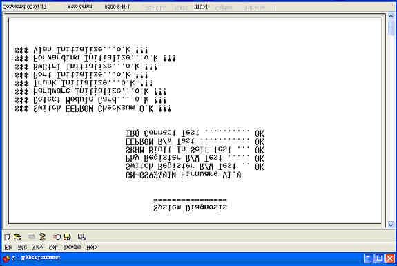
115 After a successful reboot the System Diagnosis menu will reappear. 110
116 3.3.6 TFTP Update Fireware The GN-GSV2401M provide user to update firmware or restore EEPROM value or upload current EEPROM value. 111
117 TFTP Update Firmware This page provides user use TFTP to update firmware. When save successfully and the image file download finished. Please Restart switch. TFTP Restore Configuration This page user can restore EEPROM value, save image file before, form TFTP server. When save successfully and the image file download finished. Please Restart switch. 112
118 TFTP Backup Configuration This page user can save current EEPROM value to image file. Then go to the update configure page to restore the EEPROM value. When save successfully and the image file download finished. Please Restart switch. 113
119 Chapter 4 Product Specifications 114
120 Standards: IEEE802.3, IEEE802.3u, IEEE802.3x, IEEE802.3z, and IEEE802.3ab Interface: Twenty-four 10/100 Mbps NWay ports Two 1000 Base ports NWay Protocal support: Network speed: 10M, 100M and 1000 Mbps Duplex mode: Full and Half (10M/100Mbps) Full (1000 Mbps) 4.1 Product Specifications for 10/100BASE-X port Functions Fully compliant with IEEE BASE-T, and IEEE802.3u 100BASE-TX All ports support Auto-negotiation IEEE802.3x compliant Flow Control support for Full-duplex Collision-based and carrier-based backpressure support for halfduplex 4.2 Product Specifications for 10/100/1000 BASEX port Functions Fully compliant with IEEE802.3z 1000BASE-SX, and IEEE802.3ab 1000BASE-T All ports support Auto-negotiation Full/Half duplex support IEEE802.3x compliant Flow Control support for Full-duplex ports 4.3 Product Specifications for Switching Functions IEEE802.1q port-based vlan, tag-based vlan with either IVL or SVL support IEEE802.1p two-level priority queuing support static port trunking support store-and-forward packet switching support by-port egress/ingress rate control head of line (hol) blocking prevention support 14k mac address table, 4k vlan table entries support three scheduling schemes: fcfs, strictly priority scheduling and weighted round robin scheduling to support 115
121 4.4 Product Specification for Management Functions RS-232 port interface for Console management & System configuration Console Program The 24 port switch has an RS-232 console port for direct console management (RS-232 DB-9), DTE/male connector) When connecting a terminal directly to the switching hub, use either a null modem cable or a null modem adapter on a serial (straightthrough) cable. 4.5 Physical Specification Power Supply : 110 ~ 220 V Operation Environment : Operation Temperature : 0 ~ 40 C Storage Temperature : -20 ~ 65 C Dimension (W x L x H) : 440mm x 250mm x 45mm Weight : Gross Weight g 116


122 Appendix A Configuration of the PCs The Settings Under Windows2000 Step 1. Click Start in the desktop of the Windows to select Settings, and then click Control Panel. Step 2. Double click the Network and Dial-up Connections. 117


123 Step 3. Double click the LAN CONNECTION. Step 4. Click Properties in the box under LAN CONNECTION Status. 118

, and then click the OK button to return to Local Area Connection Properties.")
124 Step 5. Double click Internet Protocol (TCP/IP). Step 6. Please assign a static IP address and the same subnet as Access Point to the computer (e.g, IP address is and Subnet Mask is ), and then click the OK button to return to Local Area Connection Properties. Click the OK button again to complete the PC configuration. 119


125 Setup Under the Windows 95/98/Me Step 1. Click Start at the desktop of the Windows, and select Settings, and then the Control Panel. Step 2. Double click Network. 120


126 Step 3. Under Network, double click the Configuration, and choose your appropriate setting TCP/IP -> and your network card below. Please choose the TCP/IP and the name of your network card. Step 4. Select the IP Address tab. Please assign a static IP address and the same subnet as Access Point to the computer (e.g, IP address is and Subnet Mask is ),and then click the OK button. 121

127 Step 5. Click the OK button again. Windows will ask you to restart your PC. Please click the Yes button. If Windows does not ask you to restart, please restart your computer anyway. Note: The Windows may ask you for the original Windows installation disk or additional files. Please insert your Windows CD-ROM into your CD-ROM drive and check the correct location, e.g., D:\win98, D:\win9x, etc. (If D is your CD-ROM drive). 122


128 Setup Under Windows XP Step 1. Click the Start at the desktop of the Windows, and select the Control Panel. Step 2. Double click the Network Connections. 123


129 Step 3. Double click the Local Area Connection. Step 4. Click the Properties in the box under Local Area Connection Status. 124

, and then click the OK button to return to Local Area Connection Properties.")
130 Step 5. Double click the Internet Protocol(TCP/IP). Step 6. Please assign a static IP address and the same subnet as Access Point to the computer (e.g, IP address is and Subnet Mask is ), and then click the OK button to return to Local Area Connection Properties. Click the OK button again to complete the PC configuration. 125
24-Port Fast + 2-Port Giga Intelligent Ethernet Switch SG9224B WEB USER GUIDE. Date: 02, Standard Version. Version: 1.02
 1 24-Port Fast + 2-Port Giga Intelligent Ethernet Switch SG9224B WEB USER GUIDE Date: 02, 2004 Standard Version Version: 1.02 1 2 I. Table of Contents 1. Introduction 1-1. SG9224B with ARM S3C4510X01 Hardware
GN-GT5D. Gigabit Ethernet Switch. User Guide. Rev.1.0 First Edition
 GN-GT5D Gigabit Ethernet Switch User Guide Rev.1.0 First Edition GN-GT5D Gigabit Ethernet Switch FCC Warning This equipment has been tested and found to comply with the limits for a Class A digital device,
6024SX G Management Switch. User s Manual. Version /12/
 6024SX2 24 +2G Management Switch User s Manual Version 10.03.01 1/12/2004-1 - 24 + 2G Single IP Management Switch User Menu 1. INTRODUCTION...5 1.2 INSTALLATION...6 1.3 INITIAL SET UP FOR MANAGEMENT...8
Managed 24-port 10/100Base-TX Layer 2 Switch. Management Guide
 Managed 24-port 10/100Base-TX Layer 2 Switch Management Guide COPYRIGHT All rights reserved. No part of this publication may be reproduced, stored in a retrieval system, or transmitted in any form or by
TEG-S2600i User s Guide
 - 1 - TEG-S2600i User s Guide 1. INTRODUCTION...6 1.2 INSTALLATION...7 1.3 INITIAL SET UP FOR MANAGEMENT...9 1.3.1 out-of-band Terminal-mode Management...9 1.3.2 In-band management through Ethernet...10
SD24GS. 24-Port Web Smart Gigabit Ethernet Switch. User s Manual
 SD24GS 24-Port Web Smart Gigabit Ethernet Switch User s Manual FCC Warning This equipment has been tested and found to comply with the limits for a Class A digital device, pursuant to Part 15 of the FCC
FriendlyNET FM2008/2009 SNMP/Web Managed Switches. User s Manual
 FriendlyNET FM2008/2009 SNMP/Web Managed Switches User s Manual Quick Start Guide Follow these steps to install the switch: 1. Open the box and check the contents. See Chapter 1 for a complete list of
LevelOne GES GE with 1 Combo SFP Web Smart Switch User Manual
 LevelOne GES-0852 8 GE with 1 Combo SFP Web Smart Switch User Manual Version 1.0-1109 1 FCC Certifications This Equipment has been tested and found to comply with the limits for a Class A digital device,
SWP-0208G, 8+2SFP. 8-Port Gigabit Web Smart Switch. User s Manual
 SWP-0208G 1 SWP-0208G, 8+2SFP 8-Port Gigabit Web Smart Switch User s Manual Version: 3.4 April 1, 2008 2 TABLE OF CONTENT 1.0 INTRODUCTION...4 1.1 MAIN FEATURES...4 1.2 START TO MANAGE THIS SWITCH...6
Managed 8 & 9 Port Switches
 Managed 8 & 9 Port Switches MIL-SM801P Eight 10/100BASE-TX Ethernet ports Plus One 100BASE-FX port MIL-SM801G Eight 10/100BASE-TX Ethernet ports Plus One 1000BASE-SX port MIL-SM800P Eight 10/100BASE-TX
AMG9082W-HP260-C User s Manual
 8 x 10/100 PoE+ 802.3at w/ 2 Gigabit Combo Ports RJ45/SFP Fast Ethernet Switch AMG9082W-HP260-C User s Manual www.amgsystems.com FCC Warning This Equipment has been tested and found to comply with the
IN-16POEGWM. User Manual. 16 Port Gigabit Ethernet + 4 Combo Gigabit SFP PoE Web Smart Switch
 IN-16POEGWM User Manual 16 Port Gigabit Ethernet + 4 Combo Gigabit SFP PoE Web Smart Switch FCC Warning This Equipment has been tested and found to comply with the limits for a Class-A digital device,
IN-16POEWM. User Manual. 16 Port Fast Ethernet PoE Web Smart Switch. Version V100817
 IN-16POEWM User Manual 16 Port Fast Ethernet PoE Web Smart Switch Version V100817 FCC Warning This Equipment has been tested and found to comply with the limits for a Class-A digital device, pursuant to
16 / 24 Ports Fast Ethernet Switches 19 Rackmount Quick Installation Guide
 16 / 24 Ports Fast Ethernet Switches 19 Rackmount Quick Installation Guide 0 FCC Certifications This Equipment has been tested and found to comply with the limits for a Class A digital device, pursuant
16-Port HPNA (Enhanced) Switch with SNMP Management
 Switch with SNMP Management") 16-Port HPNA (Enhanced) Switch with SNMP Management 1 FCC Certifications This Equipment has been tested and found to comply with the limits for a Class A digital device, pursuant to part 15 of the FCC
16-Port HPNA (Enhanced) Switch with SNMP Management 1 FCC Certifications This Equipment has been tested and found to comply with the limits for a Class A digital device, pursuant to part 15 of the FCC
Chapter 4 Configuring Switching
 Chapter 4 Configuring Switching Using the Switching Tab The navigation tabs on the top of the home page include a Switching tab that lets you manage your GS108T Gigabit Smart Switch using features under
LevelOne GSW-2472TGX. 24Fast/2 Gigabit Ethernet combo Web Smart Switch. User`s Manual
 LevelOne GSW-2472TGX 24Fast/2 Gigabit Ethernet combo Web Smart Switch User`s Manual Contents 1. INTRODUCTION...1 Features...1 Software Features...2 Package Contents...3 2. HARDWARE DESCRIPTION...5 Front
User Manual ES-5808PHG. Gigabit 8-Port 802.3at PoE Web Smart Switch
 User Manual ES-5808PHG Gigabit 8-Port 802.3at PoE Web Smart Switch Content Content I Introduction..3 Product Overview.3 Web Management Feature.3 Specification..4 Mechanical...4 Performance...5 Package
VAC 50/60Hz Power Adapter
 DGS-1216T D-Link 16-Port 10/100/1000Mbps + 2 Combo Mini GBIC Gigabit Smart Switch Before Your Begin This Quick Installation Guide gives step-by-step instructions for setting up the D-Link DGS1216T Gigabit
Managed Ethernet Switch User s Manual
 Managed Ethernet Switch User s Manual Information Coding: UM00D908 Version: V1.1 Product version: all Product Name: Managed Industrial Ethernet Switches on DIN Rail and Rack. Applicable to: Technical Support
GEU-0520 GEU QIG Manual
 GEU-0520 5-Port Gigabit Switch GEU-0820 8-Port Gigabit Switch QIG Manual V1.0-100900 1 FCC Certifications This Equipment has been tested and found to comply with the limits for a Class A digital device,
WSG18SFP Switch. User Manual
 WSG18SFP Switch User Manual Version: 01/01/2011 Introduction! 4 Product Overview! 4 Web Management Features! 4 Specifications! 5 Mechanical! 5 Performance! 5 Package Contents! 6 Hardware Description! 6
Revision PLANET NOVASwitch User's Manual FOR MODELS: GSW-800S Part No.: EM-GSW8V1
 Trademarks Copyright PLANET Technology Corp. 2002. Contents subject to revision without prior notice. PLANET is a registered trademark of PLANET Technology Corp. All other trademarks belong to their respective
FCC COMPLIANCE STATEMENT
 FCC COMPLIANCE STATEMENT This equipment has been tested and found to comply with the limits of a Class A computing devices, pursuant to Part 15 of the FCC rules. These limits are designed to provide reasonable
HES-3106-PLUS SERIES
 HES-3106-PLUS SERIES 5 PORTS 10/100/1000BASE-T ETHERNET MANAGED SWITCH WITH 1 PORT 1000BASE-X or 100/1000BASE-X UPLINK User s Guide Version 0.92 Trademarks CTS is a registered trademark of Connection Technology
HES-3109 SERIES 9 PORTS 10/100/1000BASE-T MANAGEMENT ETHERNET SWITCH
 HES-3109 SERIES 9 PORTS 10/100/1000BASE-T MANAGEMENT ETHERNET SWITCH 8 PORTS 10/100/1000BASE-T MANAGEMENT ETHERNET SWITCH WITH 1 PORT 1000BASE-X UPLINK OR 1 PORT 100/1000BASE-X UPLINK 8 PORTS 10/100/1000BASE-T
Web Smart Switch. LevelOne GES GE + 4GE SFP Web Smart Switch. User Manual. Version
 LevelOne GES-1650 16 GE + 4GE SFP Web Smart Switch User Manual Version 1.0-1109 1 FCC Certifications This Equipment has been tested and found to comply with the limits for a Class A digital device, pursuant
Trademarks. Statement of Conditions by NETGEAR, Inc. All rights reserved.
 2004 by NETGEAR, Inc. All rights reserved. Trademarks @2004 NETGEAR, Inc. NETGEAR, the Netgear logo, The Gear Guy and Everybody s connecting are trademarks of Netgear, Inc. in the United States and/or
GSW-1657 GSW User's Guide. 16/24-port Gigabit Ethernet Switch. Ver
 GSW-1657 GSW-2457 User's Guide 16/24-port Gigabit Ethernet Switch Ver.1.0.0-0803 COPYRIGHT & TRADEMARKS Specifications are subject to change without notice. Level One is a registered trademark of Digital
SWITCH RC-415/RC-416 USER S Manual
 SWITCH RC-415/RC-416 FCC Certifications This Equipment has been tested and found to comply with the limits for a Class A digital device, pursuant to part 15 of the FCC Rules. These limits are designed
Management Software AT-S101. User s Guide. For use with the AT-GS950/8POE Gigabit Ethernet WebSmart Switch. Version Rev.
 Management Software AT-S101 User s Guide For use with the AT-GS950/8POE Gigabit Ethernet WebSmart Switch Version 1.0.0 613-000985 Rev. A Copyright 2008 Allied Telesis, Inc. All rights reserved. No part
10/100/1000Mbps. Gigabit Ethernet Switch GSW-2401/GSW User's Manual
 10/100/1000Mbps Gigabit Ethernet Switch GSW-2401/GSW-1601 User's Manual Trademarks Copyright PLANET Technology Corp. 2005. Content subjects to revision without prior notice. PLANET is a registered trademark
Intelligent 4 Band VDSL 24 Ports Managed IP DSLAM with 2 Giga Ethernet USER S MANUAL
 Intelligent 4 Band VDSL 24 Ports Managed IP DSLAM with 2 Giga Ethernet USER S MANUAL Copyright Copyright 2007 All rights reserved. Trademarks Other brand and product names are registered trademarks or
Please place main product photo here.
 Please place main product photo here. 1 FCC Warning This equipment has been tested and found to comply with the limits for a Class A digital device, pursuant to Part 15 of the FCC Rules. These limitations
8-Port Fast Ethernet Switch
 TigerSwitch 10/100 8-Port Fast Ethernet Switch 8 10BASE-T/100BASE-TX ports, 1 1000BASE-T port Optional 100BASE-FX or 1000BASE-X modules 5.6 Gbps aggregate bandwidth Spanning Tree Protocol Up to four port
FWRIII-2105 SERIES. 4 ports 10/100Mbps RJ-45; built-in IEEE802.11n WiFi and 1 port 100Mbps SFP slot uplink Residential Gateway. Residential Gateway
 FWRIII-2105 SERIES 4 ports 10/100Mbps RJ-45; built-in IEEE802.11n WiFi and 1 port 100Mbps SFP slot uplink Residential Gateway 4 ports 10/100Mbps RJ-45; built-in IEEE802.11n WiFi and 1 port 100Mbps SFP
FCC Certifications. CE Mark Warning
 FCC Certifications This Equipment has been tested and found to comply with the limits for a Class A digital device, pursuant to part 15 of the FCC Rules. These limits are designed to provide reasonable
VERTICAL HORIZON VH-2402S FAST ETHERNET SWITCH MANAGEMENT GUIDE
 VERTICAL HORIZON VH-2402S FAST ETHERNET SWITCH MANAGEMENT GUIDE 9033645-01 Notice Only qualified personnel should perform installation procedures. NOTICE Enterasys Networks reserves the right to make
DES User s Guide. 8-port 10/100. Fast Ethernet Switch
 DES-2108 8-port 10/100 Fast Ethernet Switch User s Guide FCC Warning This equipment has been tested and found to comply with the limits for a Class A digital device, pursuant to Part 15 of the FCC Rules.
BEC ES08 8 ports Green Ethernet Desktop Switch User Manual
 BEC ES08 8 ports Green Ethernet Desktop Switch User Manual - 1 - The device is a powerful, high-performance Fast Ethernet switch, with all ports capable of 10 or 100Mbps auto-negotiation operation (NWay),
MR2324-4C. 24-Port Intelligent Gigabit Ethernet Switch. Management Guide
 MR2324-4C 24-Port Intelligent Gigabit Ethernet Switch Management Guide Management Guide Intelligent Gigabit Ethernet Switch with 24 10/100/1000BASE-T (RJ-45) Ports, and 4 Combination RJ-45/SFP Ports E082004-R01
10/100/1000Mbps 16/24-port Web Smart Gigabit Ethernet Switch GSW-1600S/GSW-2400S. User s Manual
 10/100/1000Mbps 16/24-port Web Smart Gigabit Ethernet Switch GSW-1600S/GSW-2400S User s Manual Trademarks Copyright PLANET Technology Corp. 2004. Contents subject to which revision without prior notice.
FSW-1610TX FSW-2410TX
 LevelOne FSW-1610TX FSW-2410TX 16/24-Port Fast Ethernet Switch User Manual Version 1.1-0609 FCC Warning This equipment has been tested and found to comply with the regulations for a Class A digital device,
Powered by Accton. ES Port Gigabit Web-Smart Switch. Management Guide.
 Powered by Accton ES4324 24-Port Gigabit Web-Smart Switch Management Guide www.edge-core.com Management Guide 24-Port Gigabit Web-Smart Switch with 24 1000BASE-T (RJ-45) Ports, and 4 Combination (RJ-45/SFP)
User Guide TL-SG1024D 24-Port Gigabit Desktop/Rackmount Switch
 User Guide TL-SG1024D 24-Port Gigabit Desktop/Rackmount Switch Rev: 1.0.0 7106503213 COPYRIGHT & TRADEMARKS Specifications are subject to change without notice. is a registered trademark of TP-LINK TECHNOLOGIES
LevelOne User Manual
 LevelOne User Manual FSW-1671 16-Port 10/100 Rackmount Smart Switch w/8 PoE Ports Ver1.0-0905 FCC Warning This Equipment has been tested and found to comply with the limits for a Class-A digital device,
SOLO NETWORK (11) (21) (31) (41) (48) (51) (61)
 (21) (31) (41) (48) (51) (61)") (11) 4062-6971 (21) 4062-6971 (31) 4062-6971 (41) 4062-6971 (48) 4062-6971 (51) 4062-6971 (61) 4062-6971 Cisco SRW224G4 24-Port 10/100 + 4-Port Gigabit Switch: WebView Cisco Small Business Managed Switches
(11) 4062-6971 (21) 4062-6971 (31) 4062-6971 (41) 4062-6971 (48) 4062-6971 (51) 4062-6971 (61) 4062-6971 Cisco SRW224G4 24-Port 10/100 + 4-Port Gigabit Switch: WebView Cisco Small Business Managed Switches
Management Software AT-S67 AT-S68. User s Guide FOR USE WITH AT-FS7016 AND AT-FS7024 SMART SWITCHES VERSION PN Rev A
 Management Software AT-S67 AT-S68 User s Guide FOR USE WITH AT-FS7016 AND AT-FS7024 SMART SWITCHES VERSION 1.0.0 PN 613-50494-00 Rev A Copyright 2003 Allied Telesyn, Inc. 960 Stewart Drive Suite B, Sunnyvale,
48-Port Gigabit Ethernet Smart Managed Plus Switch User Manual
 48-Port Gigabit Ethernet Smart Managed Plus Switch User Manual Model GS750E July 2017 202-11784-01 350 E. Plumeria Drive San Jose, CA 95134 USA Support Thank you for purchasing this NETGEAR product. You
pakedgedevice&software inc.
 pakedgedevice&software inc. SW8-4PB 8 Port Fast Ethernet with 4 Port PoE Switch User Manual Version 2.1 FCC Certifications This Equipment has been tested and found to comply with the limits for a Class
Cisco SRW208 8-Port 10/100 Ethernet Switch: WebView Cisco Small Business Managed Switches
 Cisco SRW208 8-Port 10/100 Ethernet Switch: WebView Cisco Small Business Managed Switches Secure, Reliable, Intelligent Managed Switching for Your Small Business Highlights Connects up to eight network
TE100-S16 16-Port 10/100Mbps Fast Ethernet Switch. User s Guide
 TE100-S16 16-Port 10/100Mbps Fast Ethernet Switch User s Guide FCC Warning This equipment has been tested and found to comply with the regulations for a Class A digital device, pursuant to Part 15 of the
Gigabit Network Switches
 Network Transmission Gigabit Network Switches Layer 2 (Non-PoE) Layer 3 (PoE-at) OVERVIEW This Enterprise-Class Network Switch provides 24 Gigabit Ethernet ports with 4 shared 100/1000Mbps SFP slots. This
MEG801AE-R2 Quadband VDSL Switch Part of VDSL Point to Multipoint Solution
 Manual MEG801AE-R2 Quadband VDSL Switch Part of VDSL Point to Multipoint Solution 1 GENERAL MEG801AE-R2 is an Ethernet switch with 2 10/100/1000Mbps standard RJ45 network ports and 8 VDSL Quadband ports.
GSW User Manual. 4-Port TP + 1-Port SFP Gigabit Ethernet Switch. Ver
 GSW-0508 4-Port TP + 1-Port SFP Gigabit Ethernet Switch User Manual Ver. 1.0.0-0806 1 FCC Certifications This Equipment has been tested and found to comply with the limits for a Class A digital device,
LevelOne. User Manual GSW-1656/GSW /24-Port Gigabit Switch w/ 4-Port SFP. Version
 LevelOne GSW-1656/GSW-2456 16/24-Port Gigabit Switch w/ 4-Port SFP User Manual Version 1.0-0608 FCC Certifications This Equipment has been tested and found to comply with the limits for a Class A digital
DYNAMIX 8VDSL +2 Giga Ethernet Managed 4-Band VDSL IP DSLAM User s Manual.
 DYNAMIX 8VDSL +2 Giga Ethernet Managed 4-Band VDSL IP DSLAM User s Manual. VDSL Solution The 4-Band VDSL IP DSLAM networking solution delivers cost-effective, high-performance broadband access to multiunit
FCC Certifications. CE Mark Warning
 FCC Certifications This Equipment has been tested and found to comply with the limits for a Class A digital device, pursuant to part 15 of the FCC Rules. These limits are designed to provide reasonable
5/8 Port Gigabit Ethernet Switch
 5/8 Port Gigabit Ethernet Switch User Manual Certification FCC Statement This equipment has been tested and found to comply with the limits for a Class B digital device, pursuant to part 15 of the FCC
Management Software AT-S79. User s Guide. For use with the AT-GS950/16 and AT-GS950/24 Smart Switches. Version Rev.
 Management Software AT-S79 User s Guide For use with the AT-GS950/16 and AT-GS950/24 Smart Switches Version 1.0.0 613-000207 Rev. A Copyright 2005 Allied Telesyn, Inc. All rights reserved. No part of this
DES P MANUAL WEBSMART SWITCH V1.05
 DES-1100-10P MANUAL WEBSMART SWITCH V1.05 Table of Content Getting Started...3 WEB Configuration...4 Home...4 System...5 Power Over Ethernet...6 LED Power Saving...8 Fundamentals...9 Security...21 Statistics...22
ProSAFE 8-Port and 16-Port 10-Gigabit Ethernet Web Managed Switch Models XS708Ev2 and XS716E User Manual
 ProSAFE 8-Port and 16-Port 10-Gigabit Ethernet Web Managed Switch Models XS708Ev2 and XS716E User Manual March 2017 202-11656-03 350 East Plumeria Drive San Jose, CA 95134 USA Support Thank you for purchasing
Please follow the steps to configure this Web Smart switch. Step 1: Use a twisted pair cable to connect this switch to your PC.
 Web Smart Switch Configure Please follow the steps to configure this Web Smart switch. Step 1: Use a twisted pair cable to connect this switch to your PC. Step 2: Set your PC s IP to 192.168.2.xx. Step
User Guide TL-SG1005D TL-SG1008D. 5/8-Port Gigabit Desktop Switch. alarm shop. Rev:
 User Guide TL-SG1005D TL-SG1008D 5/8-Port Gigabit Desktop Switch Rev:2.0.2 7106503707 COPYRIGHT & TRADEMARKS Specifications are subject to change without notice. is a registered trademark of TP-LINK TECHNOLOGIES
FOS-3114 Series 14-port L2+ Managed Gigabit Fiber Switch User s Guide
 FOS-3114 Series 14-port L2+ Managed Gigabit Fiber Switch User s Guide Version: 1.1 Revision History Version Date Changes 1.0 12/21/2017 First release 1.1 02/27/2018 Add the new feature FCC Warning This
12-Port Intelligent Gigabit Ethernet Switch Management Guide
 12-Port Intelligent Gigabit Ethernet Switch Management Guide Management Guide Guide 12-Port Layer 2 Switch Intelligent Gigabit Ethernet Switch with 8 10/100/1000BASE-T (RJ-45) Ports, and 4 Gigabit Combination
Cisco Small Business Managed Switches
 Cisco SRW208L 8-Port 10/100 Ethernet Switch: WebView/LX Uplink Cisco Small Business Managed Switches Secure, Reliable, Intelligent Switching for Small Businesses Highlights Connects up to eight network
SOLO NETWORK (11) (21) (31) (41) (48) (51) (61)
 (21) (31) (41) (48) (51) (61)") (11) 4062-6971 (21) 4062-6971 (31) 4062-6971 (41) 4062-6971 (48) 4062-6971 (51) 4062-6971 (61) 4062-6971 Cisco SRW208P 8-Port 10/100 Ethernet Switch: WebView/PoE Cisco Small Business Managed Switches Highly
(11) 4062-6971 (21) 4062-6971 (31) 4062-6971 (41) 4062-6971 (48) 4062-6971 (51) 4062-6971 (61) 4062-6971 Cisco SRW208P 8-Port 10/100 Ethernet Switch: WebView/PoE Cisco Small Business Managed Switches Highly
Product features. Applications
 Applications Layer 2+ VLAN static routing application The managed switch features a built-in, robust IPv4/IPv6 Layer 3 traffic static routing protocol to ensure reliable routing between VLANs and network
S7055xM / S7075xM Web Smart Managed 5-Port / 7-Port 10/100 Fast Ethernet Switch w/vlan Support Installation Guide
 S7055xM / S7075xM Web Smart Managed 5-Port / 7-Port 10/100 Fast Ethernet Switch w/vlan Support Installation Guide January 2005 VERSITRON, Inc. 83 Albe Drive / Suite C Newark, DE 19702 A050130380 The information
Signamax Connectivity Systems Manageable Gigabit Switch Model FO AF
 Manageable Gigabit Switch Signamax Connectivity Systems Manageable Gigabit Switch Model FO-065-7732AF U S E R S G U I D E User s Manual 1 Signamax Connectivity Systems Manageable Gigabit Switch Model FO-065-7732AF
Gigabit Network Switches
 Network Transmission Gigabit Network Switches Layer 2 (Non-PoE) Layer 3 (PoE-at) OVERVIEW This Enterprise-Class Network Switch provides 24 Gigabit Ethernet ports with 4 shared 100/1000Mbps SFP slots. This
WebWise. 16/24 Port Gigabit Ethernet Switch. User`s Manual
 WebWise 16/24 Port Gigabit Ethernet Switch User`s Manual Nexxt Solutions Copyright Statement Nexxt Solutions is a registered trademark. Other trademarks or brand names contained herein are the trademarks
User Guide. Unmanaged Pro Switch TL-SG105E/TL-SG108E/TL-SG116E REV4.0.1
 User Guide Unmanaged Pro Switch TL-SG105E/TL-SG108E/TL-SG116E 1910012413 REV4.0.1 May 2018 CONTENTS About This Guide Intended Readers... 1 Conventions... 1 More Information... 1 Introduction Product Overview...
User Guide. FSW-1641TX/2441TX 16/24 10/100Base-TX Web Smart Switch. FSW-1641TX 16 port 10/100Base-TX Web Smart Switch
 FSW-1641TX/2441TX 16/24 10/100Base-TX Web Smart Switch User Guide FSW-1641TX 16 port 10/100Base-TX Web Smart Switch FSW-2441TX 24 port 10/100Base-TX Web Smart Switch Contents 1. PRODUCT INTRODUCTION...1
XSNet S4124SW. This quick start guide describes how to install and use the Managed Ethernet Switch.
 Manual Quick Start Guide This quick start guide describes how to install and use the Managed Ethernet Switch. Functional Description RS-232 console, Telnet, SNMP v1 & v2c & v3, RMON, Web Browser, and TFTP
ProSAFE 8-Port 10-Gigabit Web Managed Switch Model XS708Ev2 User Manual
 ProSAFE 8-Port 10-Gigabit Web Managed Switch Model XS708Ev2 User Manual April 2016 202-11656-01 350 East Plumeria Drive San Jose, CA 95134 USA Support Thank you for purchasing this NETGEAR product. You
EZ Switch EZ Connect N SMCFS1601/SMCFS2401
 EZ Switch EZ Connect N Draft 16/24-Port 11n Wireless Fast Ethernet USB2.0 Adapter Switch SMCFS1601/SMCFS2401 COPYRIGHT & TRADEMARKS Specifications are subject to change without notice. is a registered
FCN-3112 Series. 10/100/1000TX to 1000SX SNMP Managed Media Converter. Version 1.0 User Manual
 FCN-3112 Series 10/100/1000TX to 1000SX SNMP Managed Media Converter Version 1.0 User Manual Copyright 2018 Antaira Technologies, LLC. All Rights Reserved This document contains information, which is protected
GV-PoE Switch. Multicam Digital. GV-POE0801 User's Manual
 GV-PoE Switch Multicam Digital GV-POE0801 User's Manual Before attempting to connect or operate this product, please read these instructions carefully and save this manual for future use. POE0801-A 2013
8-Port 10M/100M + 2-Port Giga (1GT+1G SFP) Web Managed PoE Switch User Manual
 Web Managed PoE Switch User Manual") 8-Port 10M/100M + 2-Port Giga (1GT+1G SFP) Web Managed PoE Switch User Manual 201309.008. A1 FCC Warning This Equipment has been tested and found to comply with the limits for a Class-A digital device,
8-Port 10M/100M + 2-Port Giga (1GT+1G SFP) Web Managed PoE Switch User Manual 201309.008. A1 FCC Warning This Equipment has been tested and found to comply with the limits for a Class-A digital device,
JetNet 5228G / 5228G-DC
 JetNet 5228G / 5228G-DC 24+4G Standalone Managed RoHS 24 10/100-TX and 4 Gigabit RJ-45/SFP combo ports (10/100/1000 Base-TX, 1000 Base-X) Design for the Building, Control Room and Telecom applications
RANGER SERIES. 150Mbps Wireless Green Broadband Router DG-BR4000NG. 150 Mbps V
 RANGER SERIES 150Mbps Wireless Green Broadband Router DG-BR4000NG N 150 Mbps V1.2 2011-12-15 FCC warning: This equipment has been tested and found to comply with the limits for a class B digital device,
The features and functions of the D-Link Smart Managed Switch can be configured through the web-based management interface.
 4 Configuration The features and functions of the D-Link Smart Managed Switch can be configured through the web-based management interface. Web-based Management After a successful login you will see the
KGS-510F Web Smart 6-Port Gigabit Ethernet Switch with Fiber Connectivity Installation Guide
 KGS-510F Web Smart 6-Port Gigabit Ethernet Switch with Fiber Connectivity Installation Guide DOC.060118-1- (C) 2005 KTI Networks Inc. All rights reserved. No part of this documentation may be reproduced
FAST ETHERNET RACKMOUNT WEB-SMART SWITCH USER MANUAL
 FAST ETHERNET RACKMOUNT WEB-SMART SWITCH USER MANUAL MODEL 505093 WITH OPTIONAL GIGABIT PORTS INT-505093-UM-0906-01 TABLE OF CONTENTS section page 1. Introduction & Features...3 2. Hardware Installation...3
SOLO NETWORK (11) (21) (31) (41) (48) (51) (61)
 (21) (31) (41) (48) (51) (61)") Cisco SRW2008MP 8-Port Gigabit Switch: WebView/Max PoE Cisco Small Business Managed Switches Secure, Reliable, Intelligent, Managed Gigabit Switching with PoE for Small Businesses Highlights Eight high-speed
Cisco SRW2008MP 8-Port Gigabit Switch: WebView/Max PoE Cisco Small Business Managed Switches Secure, Reliable, Intelligent, Managed Gigabit Switching with PoE for Small Businesses Highlights Eight high-speed
8-Port Gigabit Ethernet Smart Managed Plus Switch with 2-Port 10G/Multi-Gig Uplinks User Manual
 8-Port Gigabit Ethernet Smart Managed Plus Switch with 2-Port 10G/Multi-Gig Uplinks User Manual Model GS110EMX December 2017 202-11810-03 350 E. Plumeria Drive San Jose, CA 95134 USA Support Thank you
ProSAFE Easy-Mount 8-Port Gigabit Ethernet PoE+ Web Managed Switch
 ProSAFE Easy-Mount 8-Port Gigabit Ethernet PoE+ Web Managed Switch Model GS408EPP User Manual December 2016 202-11693-01 350 East Plumeria Drive San Jose, CA 95134 USA Support Thank you for purchasing
8 Gigabit Web Smart Switch User's Manual. Release 1.0
 8 Gigabit Web Smart Switch User's Manual Release 1.0. Table of Contents CAUTION-------------------------------------------------------------------------------------------------------------- V ELECTRONIC
SOLO NETWORK (11) (21) (31) (41) (48) (51) (61)
 (21) (31) (41) (48) (51) (61)") (11) 4062-6971 (21) 4062-6971 (31) 4062-6971 (41) 4062-6971 (48) 4062-6971 (51) 4062-6971 (61) 4062-6971 Cisco SRW208MP 8-Port 10/100 Ethernet Switch: WebView/Max PoE Cisco Small Business Managed Switches
(11) 4062-6971 (21) 4062-6971 (31) 4062-6971 (41) 4062-6971 (48) 4062-6971 (51) 4062-6971 (61) 4062-6971 Cisco SRW208MP 8-Port 10/100 Ethernet Switch: WebView/Max PoE Cisco Small Business Managed Switches
Installation Guide. Web Smart Managed 10/100 Fast Ethernet Switches with VLAN Support
 Installation Guide Web Smart Managed 10/100 Fast Ethernet Switches with VLAN Support KS-115FM-V KS-117FM-V DOC.060510-1- (C) 2006 KTI Networks Inc. All rights reserved. No part of this documentation may
XL-VCQ band VDSL Concentrator. User s Guide
 XL-VCQ802 4-band VDSL Concentrator User s Guide VDSL Solution The VDSL IP DSLAM networking solution delivers cost-effective, high-performance broadband access to multiunit buildings (hotels, apartment,
MARQUE : REFERENCE : CODIC : NETGEAR GSS108E-100EUS NOTICE
 MARQUE : REFERENCE : CODIC : NETGEAR GSS108E-100EUS 4254961 NOTICE ProSAFE 8-Port and 16-Port Gigabit Web Managed Click Switch Model GSS108E and GSS116E User Manual May 2016 202-11520-03 350 East Plumeria
SW24MGSFP 10/100/1000 Mbps + 2 Gb SFP Web Smart Ethernet Switch User Manual Version 1.0 (January 2011)
") SW24MGSFP 10/100/1000 Mbps + 2 Gb SFP Web Smart Ethernet Switch User Manual Version 1.0 (January 2011) TABLE OF CONTENTS PACKING LIST... 1 PRODUCT OVERVIEW... 3 FEATURES... 3 HARDWARE INSTALLATION... 4
SW24MGSFP 10/100/1000 Mbps + 2 Gb SFP Web Smart Ethernet Switch User Manual Version 1.0 (January 2011) TABLE OF CONTENTS PACKING LIST... 1 PRODUCT OVERVIEW... 3 FEATURES... 3 HARDWARE INSTALLATION... 4
SOLO NETWORK (11) (21) (31) (41) (48) (51) (61)
 (21) (31) (41) (48) (51) (61)") Cisco SRW2008 8-Port Gigabit Switch: WebView Cisco Small Business Managed Switches High-performance, secure switching for small businesses Highlights Eight high-speed ports to support bandwidth-intensive
Cisco SRW2008 8-Port Gigabit Switch: WebView Cisco Small Business Managed Switches High-performance, secure switching for small businesses Highlights Eight high-speed ports to support bandwidth-intensive
LevelOne GSW User Manual. 48-Port TP Fast Ethernet and 4-Port TP Gigabit w/ 2-Port shared SFP Web Smart Switch
 LevelOne GSW-5270 48-Port TP Fast Ethernet and 4-Port TP Gigabit w/ 2-Port shared SFP Web Smart Switch User Manual ii Safety FCC Warning This equipment has been tested and found to comply with the regulations
TEG-S224TX 26-Port 10/100/1000Mbps Gigabit & Fast Ethernet Switch
 TEG-S224TX 26-Port 10/100/1000Mbps Gigabit & Fast Ethernet Switch with 2 1000BASE-T plus 24 10/100BASE-T ports User s Guide FCC Warning This equipment has been tested and found to comply with the regulations
802.11b/g Access Point WL-8000AP
 802.11b/g Access Point WL-8000AP User s Guide - FCC Certifications This equipment has been tested and found to comply with the limits for a Class B digital device, pursuant to Part 15 of the FCC Rules.
FSW-1609TFX FSW-2409TFX
 LevelOne FSW-1609TFX FSW-2409TFX 16/24-Port Fast Ethernet Switch w/ fiber module slot User Manual Version 1.1-0609 FCC Warning This equipment has been tested and found to comply with the regulations for