Media Access Control (MAC) (with some IEEE 802 standards)
|
|
|
- Martha Douglas
- 5 years ago
- Views:
Transcription
 Media Access Control (MAC) (with some IEEE 802 standards) By: Dr.")
1 Department of Computer and IT Engineering University of Kurdistan Data Communication Netwotks (Graduate level) Media Access Control (MAC) (with some IEEE 802 standards) By: Dr. Alireza Abdollahpouri


2 Media Access Control Multiple access links There is collision if more than one node sends at the same time only one node can send successfully at a time 2
3 Media Access Control When a "collision" occurs, the signals will get distorted and the frame will be lost the link bandwidth is wasted during collision Question: How to coordinate the access of multiple sending and receiving nodes to the shared link? Solution: We need a protocol to determine how nodes share channel Medium Access control (MAC) protocol The main task of a MAC protocol is to minimize collisions in order to utilize the bandwidth by: - Determining when a node can use the link (medium) - What a node should do when the link is busy - What the node should do when it is involved in collision 3
4 Ideal Multiple Access Protocol 1. When one node wants to transmit, it can send at rate R bps, where R is the channel rate. 2. When M nodes want to transmit, each can send at average rate R/M (fair) 3. fully decentralized: - No special node to coordinate transmissions - No synchronization of clocks, slots 4. Simple Does not exist!! 4
5 Three Ways to Share the Media Channel partitioning MAC protocols: Share channel efficiently and fairly at high load Inefficient at low load: delay in channel access, 1/N bandwidth allocated even if only 1 active node! Taking turns protocols Eliminates empty slots without causing collisions Vulnerable to failures (e.g., failed node or lost token) Random access MAC protocols Efficient at low load: single node can fully utilize channel High load: collision overhead 5
6 Multiple Access Protocols Contention-based Contention free 6
7 Channel Partitioning: TDMA TDMA: time division multiple access Access to channel in "rounds" Each station gets fixed length slot in each round Time-slot length is packet transmission time Unused slots go idle Example: 6-station LAN with slots 1, 3, and 4 7
8 Channel Partitioning: FDMA FDMA: frequency division multiple access Channel spectrum divided into frequency bands Each station assigned fixed frequency band Unused transmission time in bands go idle Example: 6-station LAN with bands 1, 3, and 4 8
9 Channel Partitioning: CDMA CDMA: Code division multiple access One channel carries all transmissions simultaneously Two properties: If we multiply each code by another, we get 0. If we multiply each code by itself, we get 4 Data = (d 1. c 1 + d 2. c 2 + d 3. c 3 + d 4. c 4 ). c 1 = d 1. c 1. c 1 + d 2. c 2. c 1 + d 3. c 3. c 1 + d 4. c 4. c 1 = 4. d 1 9
10 CDMA: Chips Sequence of numbers called chips Orthogonal sequences have the following properties: Each sequence is made of N elements, where N is the number of stations If we multiply a sequence by a number, every element in the sequence is multiplied by that element (scalar multiplication) If we multiply two equal sequence, element by element, and add the results, we get N (inner product) If we multiply two different sequence, element by element, and add the results, we get 0 Adding two sequence means adding the corresponding elements. The result is another sequence Data representation in CDMA 10
11 CDMA: Encoding and Decoding Show how four stations share the link during a 1-bit interval 11
12 CDMA: Signal Level Digital signal created by four stations in CDMA using NRZ-L for simplicity 12
13 CDMA: Decoding Show how station 3 can detect the data by station 2 by using the code for station 2 Decoding of the composite signal for one in CDMA 13
 14")
14 Evolution of Contention Protocols Aloha Developed in the 1970s for a packet radio network Slotted Aloha Improvement: Start transmission only at fixed times (slots) CSMA CSMA = Carrier Sense Multiple Access Improvement: Start transmission only if no transmission is ongoing CSMA/CD CD = Collision Detection Improvement: Stop ongoing transmission if a collision is detected (e.g. Ethernet) 14
15 ALOHA Pure ALOHA Developed by Abramson in the 1970s for a packet radio network by Hawaii University. Whenever a station has a data, it transmits immediately. Sender finds out whether transmission was successful or experienced a collision by listening to the broadcast from the destination station. Sender retransmits after some random time if there is a collision. Slotted ALOHA Improvement: Time is slotted and a packet can only be transmitted at the beginning of one slot. Thus, it can reduce the collision duration. 15
16 ALOHA Mountainous islands land network difficult to install Fully decentralized protocol ACK ACK ACK ACK The node waits for an ACK for time-out equals to the maximum round-trip propagation delay = 2* t prop 16


17 Frame Transmission in pure ALOHA If the frame is collided (no ACK was received) the stations wait for a random time and retransmit the frame again. 17
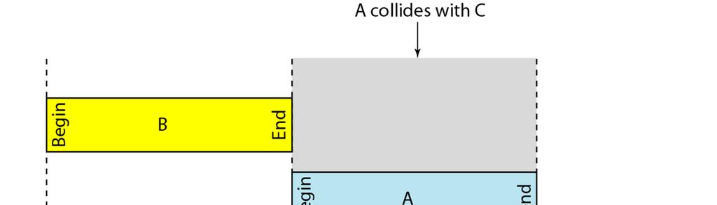
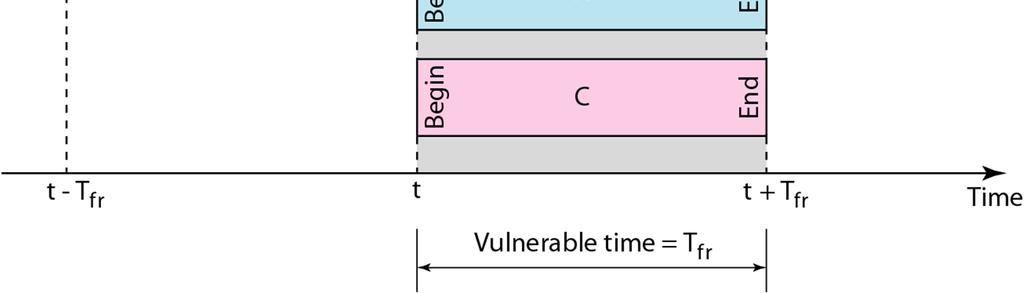
18 Throughput Analysis Frame which collides with start of red frame Frame which collides with end of red frame Frame t 0 -F t 0 t 0 +F Vulnerable Period of red frame Time A frame (red frame) will be in a collision if and only if another transmission begins in the vulnerable period of the frame Vulnerable period has the length of 2 frame times 18
19 Vulnerable time- example A pure ALOHA network transmits 200-bit frames on a shared channel of 200 kbps. What is the requirement to make this frame collision-free? Solution Average frame transmission time T fr is 200 bits/200 kbps or 1 ms. The vulnerable time is 2 1 ms = 2 ms. This means no station should send later than 1 ms before this station starts transmission and no station should start sending during the one 1-ms period that this station is sending. 19
20 Throughput Analysis S MAC Physical MAC Physical MAC Physical MAC Physical G S: throughput, average number of successful frame transmissions per second G: load, average number of transmission attempts by all nodes during one frame transmission time 20
21 Throughput Analysis P success : Probability that a frame transmission is successful = Probability that there are no additional transmissions in the vulnerable period The probability of k transmission-attempts during the vulnerable period: P success =P (0)=e -2G S=GP success =Ge -2G 21
22 Throughput Analysis S Max throughput=0.184 Aloha For small G: S G, there is nearly no collision, S is small because the load is small For large G: G >> S, there are many backlogged users, S is small because there are many collisions G 22
23 ALOHA Throughput - example A pure ALOHA network transmits 200-bit frames on a shared channel of 200 kbps. What is the throughput if the system (all stations together) produces a frames per second b. 500 frames per second c. 250 frames per second. Solution The frame transmission time is 200/200 kbps or 1 ms. a. If the system creates 1000 frames per second, this is 1 frame per millisecond. The load is 1. In this case S = G e 2 G or S = (13.5 percent). This means that the throughput is = 135 frames. Only 135 frames out of 1000 will probably survive. 23
24 ALOHA Throughput - example b. If the system creates 500 frames per second, this is (1/2) frame per millisecond. The load is (1/2). In this case S = G e 2G or S = (18.4 percent). This means that the throughput is = 92 and that only 92 frames out of 500 will probably survive. Note that this is the maximum throughput case, percentagewise. c. If the system creates 250 frames per second, this is (1/4) frame per millisecond. The load is (1/4). In this case S = G e 2G or S = (15.2 percent). This means that the throughput is = 38. Only 38 frames out of 250 will probably survive. 24


25 Slotted ALOHA time divided into discrete intervals (1 interval = 1 frame) the sending station waits until the beginning of the next discrete interval 25
26 Throughput for slotted ALOHA S=Ge -G 26
27 Pure and Slotted ALOHA Throughput S 0.3 Slotted Aloha Aloha G Simple improvement but big impact 6 8 G 27
28 Slotted ALOHA Throughput - example A slotted ALOHA network transmits 200-bit frames on a shared channel of 200 kbps. What is the throughput if the system (all stations together) produces a frames per second b. 500 frames per second c. 250 frames per second. Solution The frame transmission time is 200/200 kbps or 1 ms. a. If the system creates 1000 frames per second, this is 1 frame per millisecond. The load is 1. In this case S = G e G or S = (36.8 percent). This means that the throughput is = 368 frames. Only 386 frames out of 1000 will probably survive. 28
29 Slotted ALOHA Throughput - example b. If the system creates 500 frames per second, this is (1/2) frame per millisecond. The load is (1/2). In this case S = G e G or S = (30.3 percent). This means that the throughput is = 151. Only 151 frames out of 500 will probably survive. c. If the system creates 250 frames per second, this is (1/4) frame per millisecond. The load is (1/4). In this case S = G e G or S = (19.5 percent). This means that the throughput is = 49. Only 49 frames out of 250 will probably survive. 29
30 CSMA (Carrier Sense Multiple Access) Collisions hurt the efficiency of ALOHA protocol At best, channel is useful 37% of the time CSMA gives improved throughput compared to Aloha protocols. CSMA: listen before transmit If channel sensed idle: transmit entire frame If channel sensed busy, defer transmission Human analogy: don t interrupt others! 30

31 CSMA Collisions Collisions can still occur: propagation delay means two nodes may not hear each other s transmission Collision: entire packet transmission time wasted 31

32 Kinds of CSMA Non-persistent CSMA CSMA Persistent CSMA 1-persistent CSMA p-persistent CSMA 32


33 Nonpersistent vs. persistent reduces chance of collisions reduces the efficiency increases the chance for collisions 1-persistant p-persistent Decrease the chance for collisions Improves efficiency 33
34 CSMA/CD (Collision Detection) CSMA/CD: carrier sensing, deferral as in CSMA Collisions detected within short time Colliding transmissions aborted, reducing wastage Collision detection Easy in wired LANs: measure signal strengths, compare transmitted, received signals Difficult in wireless LANs: receiver shut off while transmitting Human analogy: the polite conversationalist 34


35 CSMA/CD Collision Detection CSMA CSMA/CD 35
36 Minimum Packet Size Why put a minimum packet size? Give a host enough time to detect collisions In Ethernet, minimum packet size = 64 bytes (two 6-byte addresses, 2-byte type, 4-byte CRC, and 46 bytes of data) If host has less than 46 bytes to send, the adaptor pads (adds) bytes to make it 46 bytes What is the relationship between minimum packet size and the length of the LAN? 36
37 CSMA/CD- Collision detection interval T 0 A begins transmission A B T 0 +α-ε B begins transmission A B T 0 +α B detects collision A B T 0 +2α -ε Time A detects collision just before end of transmission A (α is the propagation time) B 37
38 Collision detection How the station detects a collision? There are many collision detection methods! Most of them are analog processes Examples: detecting voltage level on the line detecting power level detecting simultaneous transmission & reception 38
39 CSMA/CD Contention Interval t 0 t 1 Contention Slots Frame Frame Frame Frame Contention interval Idle time Contention slots end in a collision Contention interval is a sequence of contention slots Length of a slot in contention interval is 512 bit time 39
40 Throughput Comparison S Aloha 0.1-persistent CSMA 0.5-persistent CSMA Slotted Aloha 1-persistent CSMA 0.01-persistent CSMA Nonpersistent CSMA G 40
41 Controlled Access Protocols In controlled access, the stations consult one another to find which station has the right to send. A station cannot send unless it has been authorized by other stations. Topics discussed in this section: Reservation Polling Binary Countdown Token Passing 41
 not good if N is large high-load utilization")
42 Reservation access method No collisions reservation is made before sending t N bits d bits average waiting time before transmission is N low load utilization: d/(d+n) not good if N is large high-load utilization d/(d+1) 42


43 Polling Poll primary device wants to send data Select primary device is ready to receive secondary All data exchanges made through the primary device primary device controls the channel and is initiator of the session 43
44 Polling (cnt d) Offers higher efficiency than the random access protocols Drawbacks: polling delay node transmits at rate less than R bps channel becomes inoperative if master device fails Remember 4 protocol issues? - if only 1 node is sending than the throughput is R - when M nodes have data to send than the throughput is R/M - decentralized protocol simple & inexpensive to implement 44
45 The binary countdown protocol A dash indicates silence Channel efficiency d/(d+log2 N) If the source address is at the beginning than efficiency is 100 %! stations with larger numbers have better chances to access the medium 45
46 The binary countdown protocol-variation Stations D, E, A, F, B, G with priorities 6, 5, 4, 3, 2, 1 If station D has sent a frame than the new order is E, A, F, B, G, D with priorities 6, 5, 4, 3, 2, 1 Stations get more equal chance to access the medium 46


47 Token passing A token is a small packet that circulates throughout the network from Computer to Computer in an orderly fashion. If a workstation wants to transmit a message, first it must seize the token. 47
48 Token passing Logical ring and physical topology in token-passing access method 48
49 Limited-contention protocols performance measures: low load (ALOHA CS method) channel high load (collision-free protocols) the best is to have a combined performance decrease the amount of competition succesfuly acquired channel Pr ( success with optimal kp(1 k 1 p) = k k 1 p) k 1 49
50 Adaptive Tree Walk Protocol U.S. Army test for Syphilis - Test group, if negative all ok - If positive, then split in two and re-test 50
51 Adaptive Tree Walk Protocol Where to begin searching (entire army?) if heavily loaded, not at the top since there will always be a collision Number levels 0, 1, 2 At level i, 1/2 i stations below it ex: level 0, all stations below it, 1 has 1/2 below If q stations want to transmit, then q/2 i below Want number below to be 1 (no collisions) q/2 i = 1, i = log 2 q 51
52 ATWP- Improvement If collision at 1, 2 idle, do we need to search 3? 52
53 IEEE Standards for LANs 53


54 IEEE 802 Project for DL and Phy. Layers 54

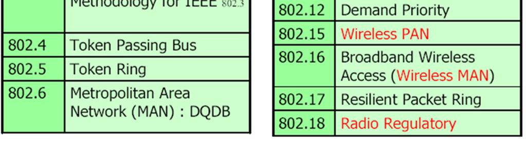
55 IEEE 802 standards 55
56 IEEE 802 Standards (Ethernet: 802.3) 56

57 Ethernet (IEEE 802.3) The Ethernet is the most successful local area networking technology. Ethernet provides Unreliable Connectionless service Developed at Xerox Park by Robert Metcalfe and David Boggs, it is a general form of the Carrier Sense Multiple Access with Collision Detection (CSMA/CD) technology. 57
58 Ethernet (IEEE 802.3) Digital Equipment Corporation (DEC), Intel and Xerox joined to form the 10 Mbps Ethernet standard in This standard formed the basis of the IEEE standard It has recently been extended to include a 100 Mbps version, called Fast Ethernet and a 1000 Mbps version called Gigabit Ethernet. 58
59 IEEE specification Various standard defined for IEEE Base5 -- thick coaxial (BUS topology) 10Base2 -- thin coaxial (BUS topology) 10BaseT -- twisted pair (Star topology) 10BaseF -- fiber optics (Star topology) Fast Ethernet 100BaseTX, 100BaseT4, 100BaseF and 100 VG-AnyLAN Gigabit Ethernet 1000BaseX, 1000BaseTX, 1000BaseSX, 1000BaseLX 10 Base 5 data rate in Mbps signaling baseband or broadband maximum segment length in hundreds of meters 59
60 10Base5 tap : cable does not to be cut transceiver : send/receive, collison detection, electronics isolation AUI : Attachment Unit Interface Use for backbone networks vampire tap maximum segment length=500m maximum number of stations per segment=100 Thick coax BNC connector transceiver Repeater AUI cable minimum distance between two stations = 2.5 m maximum network distance between two stations = 2.5km NIC 60
61 10Base2 BNC connector No drop cable use for office LAN Thin coax BNC T-connector maximum segment length=185m maximum number of stations per segment=30 NIC minimum distance between two stations = 0.5 m maximum network distance between two stations = 925 m 61


62 10Base2 Uses thin coax that is cheaper and easier to install than thick Ethernet coax Transceiver electronics built into NIC; NIC connects directly to network medium Useful when many computers are located close to each other May be unreliable - any disconnection disrupts entire net 62


63 10BaseT Replaces AUI cable with twisted pair cable Replaces thick coax with hub Use for office LAN Hub maximum cable length = 100m NIC 63


64 10BaseF 10BaseF specification enable long distance connections with the use of optical fiber. Fiber port 64
65 Ethernet Frame Format Bytes Preamble SF Source Dest. Length Data Pad Checksum Preamble: 7 bytes of (used for synchronization) Start Frame (SF): Source and destination: MAC addresses E.g. 00:45:A5:F3:25:0C Broadcast: FF:FF:FF:FF:FF:FF 65
66 Ethernet Frame Format Bytes Preamble SF Source Dest. Length Data Pad FCS Length: defines the length of the Data field. Minimum packet length of 64 bytes (to detect collision) PAD: Frame must be at least 64 bytes long, so if the data is shorter than 46 bytes, the pad field must compensate FCS (Frame Check Sequence): for error detection Checked at receiver. If error is detected, the frame is simply dropped 66
67 Ethernet Uses CSMA/CD Carrier sense: wait for link to be idle Channel idle: start transmitting Channel busy: wait until idle Collision detection: listen while transmitting No collision: transmission is complete Collision: abort transmission, and send jam signal Random access: exponential back-off After collision, wait a random time before trying again 67


68 Exponential Backoff Algorithm Ethernet uses the exponential backoff algorithm to determine when a station can retransmit after a collision Algorithm: Set slot time equal to 512bit time After first collision wait 0 or 1 slot times After i-th collision, wait a random number between 0 and 2 i -1 time slots Do not increase random number range, if =10 Give up after 16 collisions 68
69 IEEE 802 Standards (Token Bus: 802.4) 69

70 IEEE 802.4: Token Bus Physical topology: BUS Logical topology: Ring 70

71 Token Passing in a Token Bus Network 71
72 Token Passing in a Token Bus Network 72
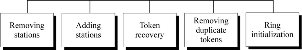
73 Ring Management 73
74 IEEE 802 Standards (Token Ring: 802.5) 74
75 IEEE 802.5: Token Ring Proposed in 1969 and initially referred to as a Newhall ring. Token ring :: a number of stations connected by transmission links in a ring topology. Information flows in one direction along the ring from source to destination and back to source. Medium access control is provided by a small frame, the token, that circulates around the ring when all stations are idle. Only the station possessing the token is allowed to transmit at any given time. 75
76 Token Ring IEEE Listen: Talk: Data Token/Data l 4 l 1 l 3 l 2 PROP = i li / c = TRT min TRT=Token Rotation Time 76

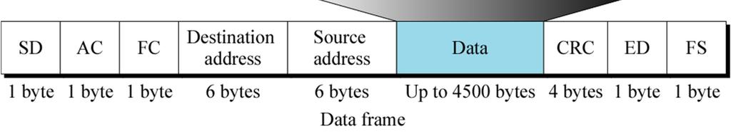
77 Data Frames 77

78 SD (Start Delimiter) Field The J and K violations are created at the physical layer * Differential encoding: each bit has two transitions: one at the beginning of the bit the second at the middle of the bit * J violation: both transitions are cancelled * K violation: the middle transition is cancelled 78

79 AC (Access Control) Field 0: token 1: data frame Set to 0 by the sending station Changed to 1 by the monitor station to remove an errant frame if it happens IEEE provides a procedure for the selection of a station to become an active monitor 79

80 FC (Frame Control) Field To indicate if it is control information or data in the PDU Determines how to use the info in the AC field 80
")
81 ED (End Delimiter) Field 81

82 FS (Frame Status) Field Repeated to prevent errors because no error checking is performed on this part (inserted after the frame leaves the sender) Can be set * by the receiver to indicate that the frame has been read or * by the monitor to indicate that the frame has been around the ring Not an ACK, but it does tell the sender that the frame can now be discarded 82
83 Token Frame Really a placeholder and reservation frame, only 3 bytes long SD: a frame is coming AC: indicates the frame is a token and includes priority and reservation fields ED: the end of the frame 83
84 Token Ring Operation Whenever the network is unoccupied, it circulates a simple three-byte token. This token is passed from NIC to NIC in sequence until it encounters a station with data to send. That station waits for the token to enter its network board. If the token is free the station may send a data frame. This data frame proceeds around the ring regenerated by each station. 84
85 Token Ring Operation Each intermediate station examines the destination address, if the frame is addressed to another station, the station relays it to its neighbor. If the station recognizes its own address, copies the message, checks for errors, and changes four bits in the last byte of the frame to indicate address recognized and frame copied. The full packet then continues around the ring until it returns to the station that sent it. 85
86 Token Ring Operation The sender receives the frame and recognizes itself in the source address field. It then checks the addressrecognized and frame copied bits. If they are set, it knows that the frame was received. The sender then discards the used data frame and releases the token back to the ring. 86
87 Token Ring Operation 87
88 Priority and reservation A busy token can be reserved by a station waiting to transmit regardless of that station s location on the ring. Each station has a priority code. As a frame passes by, a station waiting to transmit it may reserve the next open token by entering its priority code in the access control (AC) field of the token or data frame. A station with a higher priority may remove a lower priority reservation and replace it with its own. 88
89 Monitor station Several problems may occur to disrupt the operation of a token ring network. 1. A station may neglect to retransmit a token 2. A token may be destroyed by noise 3. A sending station may not release the token once its turn has ended 4. A sending station may neglect to remove its used data frame from the ring To handle these situations, one station on the ring is designated as monitor station. 89
90 Monitor station The monitor sets a timer each the token passes. If the token does not reappear in the allotted time, it is presumed to be lost and the monitor generates a new token and introduces it into the ring. The monitor guards against perpetually recirculating data frames by setting a bit (status bit) in the AC (access control) field of each frame. If the status bit has been set, it knows that the packet has already been around the ring and should be discarded. The monitor destroys the frame and puts a token into the ring. 90
91 IEEE 802 Standards (WiFi: ) 91
92 Wireless Link Characteristics Differences from wired link. decreased signal strength: radio signal attenuates as it propagates through matter (path loss) interference from other sources: standardized wireless network frequencies (e.g., 2.4 GHz) shared by other devices (e.g., phone); devices (motors) interfere as well multipath propagation: radio signal reflects off objects ground, arriving ad destination at slightly different times. make communication across (even a point to point) wireless link much more difficult 92

 or mobile wireless does not always")
93 Elements of a Wireless Network network infrastructure wireless hosts laptop, PDA, IP phone run applications may be stationary (nonmobile) or mobile wireless does not always mean mobility 93
 in its area e.g., cell towers, 802.")
94 Elements of a Wireless Network network infrastructure base station typically connected to wired network relay - responsible for sending packets between wired network and wireless host(s) in its area e.g., cell towers, access points 94
95 Elements of a Wireless Network network infrastructure wireless link typically used to connect mobile(s) to base station also used as backbone link multiple access protocol coordinates link access various data rates, transmission distance 95


96 Distance Sensitivity in Wireless Networks SNR QPSK 16QAM 64QAM Distance 96
97 IEEE WLAN architecture defines two BSS (Basic Service Set) options: Infrastructure BSS wired LAN Independent BSS (Ad-Hoc network) 97
98 Infrastructure BSS This is by far the most common way of implementing WLANs. Infrastructure BSS wired LAN The base stations connected to the wired infrastructure are called access points (AP). Wireless stations in an Infrastructure BSS must always communicate via the AP (never directly). Before stations can use the BSS: Association. 98
99 Independent BSS (Ad-Hoc configuration) Very hot topic for research- So many new applications No access point is required, stations can communicate directly. Efficient routing of packets is not a trivial problem (routing is not a task of ). Independent BSS (Ad-Hoc network) Ad-Hoc WLAN networks are outside the scope of this course. 99
100 Extended Service Set (ESS) This is a larger WLAN network consisting of a number of BSS networks interconnected via a common backbone AP AP AP supports link-layer mobility within an ESS (but not outside the ESS) 100

101 IEEE Physical Layer IEEE specifies different Physical layer techniques for


102 Multi-carrier transmission Single carrier Multi carrier Convert a serial high rate data stream on to multiple parallel low rate sub-streams. 102
103 OFDM vs. FDM High spectral efficiency: The sub-channels are made orthogonal to each other over the OFDM symbol duration. Spacing is carefully selected. Allow the sub-channels to overlap in the frequency domain. Allow sub-carriers to be spaced as close as theoretically possible. FDM save of bandwidth OFDM OFDM: Orthogonal Frequency Division Multiplexing 103

104 Frequency hopping Spread Spectrum (FHSS) This dilemma was recognized prior to WWII. In 1942, Hedy Lamarr and pianist George Antheil patented a Secret Communication System. Their scheme was for a frequency hopping remote control for torpedo guidance. Hedy Lamarr Actress and co-inventor of frequency hopping spread spectrum 104
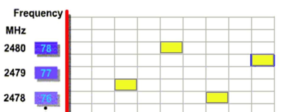
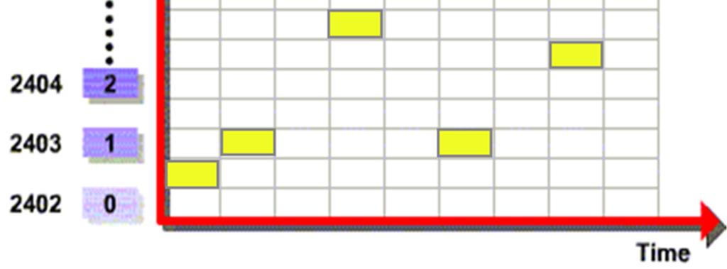
105 FHSS 105
106 Direct Sequence Spread Spectrum (DSSS) In a DSSS system the message bit stream is modified by a higher rate sequence (called a chip sequence). Chipping Code (Barker Sequence) Original Data One Bit One Bit Spread Data
 802.11g (up to 54 Mbps) 802.")
107 ISM Bands (Unlicensed ) b (up to 11Mbps) g (up to 54 Mbps) a (up to 54 Mbps) 107
108 802.11b Introduced in 1999 Uses the unlicensed 2.4 GHz band Same band as cordless phones, microwave ovens 5.5 and 11 Mbps data rates Practical throughput with TCP is only 5.9 Mbps 11 channels (in the US). Only 1, 6, and 11 are non-overlapping 108
109 802.11a/g a Uses the 5 GHz band 6, 9, 12, 18, 24, 36, 48, 54 Mbps Switches from CCK to Orthogonal Frequency Division Multiplexing (OFDM) Each frequency is orthogonal g Introduced in 2003 Uses OFDM to improve performance (54 Mbps) Backwards compatible with b 109
110 802.11n/ac n Introduced in 2009 Multiple Input Multiple Output (MIMO) Multiple send and receive antennas per devices (up to four) Data stream is multiplexed across all antennas Maximum 600 Mbps transfer rate (in a 4x4 configuration) 300 Mbps is more common (2x2 configuration) ac Almost finished, draft standard 8x8 MIMO in the 5 GHz band, 500 Mbps 1 GBps rates 110
111 Difference Between Wired and Wireless Ethernet LAN Wireless LAN B A B C A C If both A and C sense the channel to be idle at the same time, they send at the same time. Collision can be detected at sender in Ethernet. Half-duplex radios in wireless cannot detect collision at sender. 111
112 Hidden terminal problem Multiple wireless senders and receivers create additional problems (beyond multiple access): C A B C A B A s signal strength C s signal strength Hidden terminal problem B, A hear each other B, C hear each other A, C can not hear each other means A, C unaware of their interference at B space Signal attenuation: B, A hear each other B, C hear each other A, C can not hear each other interfering at B 112
113 Virtual carrier sensing (with RTS and CTS) idea: allow sender to reserve channel rather than random access of data frames: avoid collisions of long data frames RTS = Request-to-Send RTS A B C D E F 113
114 Virtual carrier sensing (with RTS and CTS) RTS = Request-to-Send RTS A B C D E F B hears RTS, becomes silent 114
115 Virtual carrier sensing (with RTS and CTS) CTS = Clear-to-Send CTS A B C D E F 115
116 Virtual carrier sensing (with RTS and CTS) CTS = Clear-to-Send CTS A B C D E F E hears CTS, becomes silent 116
117 Virtual carrier sensing (with RTS and CTS) DATA A B C D E F ACK A B C D E F 117
118 MAC: CSMA/CA request to send timer clear to send network allocation vector The use of virtual channel sensing using CSMA/CA. C can hear A (RTS) and D can hear B (CTS) 118
119 Collision Avoidance: RTS-CTS exchange A AP B DATA (A) defer time 119
120 frame: addressing frame control duration address 1 address 2 address 3 Seq Control address 4 payload CRC Address 1: MAC address of wireless host or AP to receive this frame Address 2: MAC address of wireless host or AP transmitting this frame Address 3: MAC address of router interface to which AP is attached Address 4: used only in ad hoc mode 120
121 frame: addressing H1 R1 router Internet R1 MAC addr H1 MAC addr dest. address source address frame AP MAC addr H1 MAC addr R1 MAC addr address 1 address 2 address frame 121
122 MAC (fragmentation) Wireless environments very noisy! Probability of frame to be transmitted successfully inversely proportional to the frame length Frame length If bit error p then successful frame transmission (1-p) n - for p=10-4 and frame size of 1000 bytes, almost 55% of frames are damaged. Damaged frames have to be retransmitted Solution: Each frame fragmented with fragments having their own FCS The fragments are ACKn d using Stop-and-Wait protocol 122
123 CSMA/CA with frame fragmentation A fragment burst. Only damaged fragments retransmitted -throughput increased NAV keeps the other station quiet only until the next ACK How to transmit whole frame without interference? (using SIFS) 123
124 Interframe spacing in SIFS: Short Inter-Frame Space (28 microseconds) PIFS: PCF Inter-Frame Space (78 microseconds) DIFS: Distributed Inter-Frame Space (128 microseconds) EIFS: Extended Inter-Frame Space 124


125 Questions 125
Shared Access Networks Wireless. 1/27/14 CS mywireless 1
 Shared Access Networks Wireless 1 Wireless and Mobile Networks Background: # wireless (mobile) phone subscribers now exceeds # wired phone subscribers (5-to-1)! # wireless Internet-connected devices equals
MULTIPLE ACCESS PROTOCOLS 2. 1
 MULTIPLE ACCESS PROTOCOLS AND WIFI 1 MULTIPLE ACCESS PROTOCOLS 2. 1 MULTIPLE ACCESS LINKS, PROTOCOLS Two types of links : point-to-point broadcast (shared wire or medium) POINT-TO-POINT PPP for dial-up
Getting Connected (Chapter 2 Part 4) Networking CS 3470, Section 1 Sarah Diesburg
 Networking CS 3470, Section 1 Sarah Diesburg") Getting Connected (Chapter 2 Part 4) Networking CS 3470, Section 1 Sarah Diesburg Five Problems Encoding/decoding Framing Error Detection Error Correction Media Access Five Problems Encoding/decoding Framing
Getting Connected (Chapter 2 Part 4) Networking CS 3470, Section 1 Sarah Diesburg Five Problems Encoding/decoding Framing Error Detection Error Correction Media Access Five Problems Encoding/decoding Framing
Goals. Fundamentals of Network Media. More topics. Topics. Multiple access communication. Multiple access solutions
 Fundamentals of Network Media Local Area Networks Ursula Holmström Goals Learn the basic concepts related to LAN technologies, for example use of shared media medium access control topologies Know the
Chapter 12 Multiple Access 12.1
 Chapter 12 Multiple Access 12.1 Copyright The McGraw-Hill Companies, Inc. Permission required for reproduction or display. 12.2 Figure 12.1 Data link layer divided into two functionality-oriented sublayers
Wireless Networks. CSE 3461: Introduction to Computer Networking Reading: , Kurose and Ross
 Wireless Networks CSE 3461: Introduction to Computer Networking Reading: 6.1 6.3, Kurose and Ross 1 Wireless Networks Background: Number of wireless (mobile) phone subscribers now exceeds number of wired
Computer Networks. Medium Access Sublayer (Part I)
") Computer Networks Medium Access Sublayer (Part I) Topics Introduction Multiple Access Protocols Ethernet Wireless LAN Protocols Bridges Misc (brief) High-Speed LANs Satellite Networks Introduction Remember,
Computer Networks Medium Access Sublayer (Part I) Topics Introduction Multiple Access Protocols Ethernet Wireless LAN Protocols Bridges Misc (brief) High-Speed LANs Satellite Networks Introduction Remember,
CS 43: Computer Networks. 27: Media Access Contd. December 3, 2018
 CS 43: Computer Networks 27: Media Access Contd. December 3, 2018 Last Class The link layer provides lots of functionality: addressing, framing, media access, error checking could be used independently
Links Reading: Chapter 2. Goals of Todayʼs Lecture. Message, Segment, Packet, and Frame
 Links Reading: Chapter 2 CS 375: Computer Networks Thomas Bressoud 1 Goals of Todayʼs Lecture Link-layer services Encoding, framing, and error detection Error correction and flow control Sharing a shared
Topics. Link Layer Services (more) Link Layer Services LECTURE 5 MULTIPLE ACCESS AND LOCAL AREA NETWORKS. flow control: error detection:
 Link Layer Services LECTURE 5 MULTIPLE ACCESS AND LOCAL AREA NETWORKS. flow control: error detection:") 1 Topics 2 LECTURE 5 MULTIPLE ACCESS AND LOCAL AREA NETWORKS Multiple access: CSMA/CD, CSMA/CA, token passing, channelization LAN: characteristics, i basic principles i Protocol architecture Topologies
1 Topics 2 LECTURE 5 MULTIPLE ACCESS AND LOCAL AREA NETWORKS Multiple access: CSMA/CD, CSMA/CA, token passing, channelization LAN: characteristics, i basic principles i Protocol architecture Topologies
Wireless Local Area Networks. Networks: Wireless LANs 1
 Wireless Local Area Networks Networks: Wireless LANs 1 Wireless Local Area Networks The proliferation of laptop computers and other mobile devices (PDAs and cell phones) created an obvious application
CS 43: Computer Networks Media Access. Kevin Webb Swarthmore College November 30, 2017
 CS 43: Computer Networks Media Access Kevin Webb Swarthmore College November 30, 2017 Multiple Access Links & Protocols Two classes of links : point-to-point dial-up access link between Ethernet switch,
Wireless and Mobile Networks 7-2
 Wireless and Mobile Networks EECS3214 2018-03-26 7-1 Ch. 6: Wireless and Mobile Networks Background: # wireless (mobile) phone subscribers now exceeds # wired phone subscribers (5-to-1)! # wireless Internet-connected
Medium Access Control
 Medium Access Control All material copyright 1996-2009 J.F Kurose and K.W. Ross, All Rights Reserved 5: DataLink Layer 5-1 Link Layer Introduction and services Multiple access protocols Ethernet Wireless
Wireless Communications
 4. Medium Access Control Sublayer DIN/CTC/UEM 2018 Why do we need MAC for? Medium Access Control (MAC) Shared medium instead of point-to-point link MAC sublayer controls access to shared medium Examples:
ECE 4450:427/527 - Computer Networks Spring 2017
 ECE 4450:427/527 - Computer Networks Spring 2017 Dr. Nghi Tran Department of Electrical & Computer Engineering Lecture 5.6: Wireless Networks - MAC Dr. Nghi Tran (ECE-University of Akron) ECE 4450:427/527
Chapter 6 Wireless and Mobile Networks
 Chapter 6 Wireless and Mobile Networks Computer Networking: A Top Down Approach Featuring the Internet, 3 rd edition. Jim Kurose, Keith Ross Addison-Wesley, July 2004. 6: Wireless and Mobile Networks 6
Medium Access Control Sublayer
 Wireless (WLAN) Medium Access Control Sublayer Mahalingam Mississippi State University, MS October 20, 2014 Outline Medium Access Protocols Wireless (WLAN) 1 Medium Access Protocols ALOHA Slotted ALOHA
Data Communication & Networks G Session 5 - Main Theme Wireless Networks. Dr. Jean-Claude Franchitti
 Data Communication & Networks G22.2262-001 Session 5 - Main Theme Wireless Networks Dr. Jean-Claude Franchitti New York University Computer Science Department Courant Institute of Mathematical Sciences
Multiple Access Links and Protocols
 Multiple Access Links and Protocols Two types of links : point-to-point PPP for dial-up access point-to-point link between Ethernet switch and host broadcast (shared wire or medium) old-fashioned Ethernet
6.9 Summary. 11/20/2013 Wireless and Mobile Networks (SSL) 6-1. Characteristics of selected wireless link standards a, g point-to-point
 6-1. Characteristics of selected wireless link standards a, g point-to-point") Chapter 6 outline 6.1 Introduction Wireless 6.2 Wireless links, characteristics CDMA 6.3 IEEE 802.11 wireless LANs ( wi-fi ) 6.4 Cellular Internet Access architecture standards (e.g., GSM) Mobility 6.5
Chapter 6 outline 6.1 Introduction Wireless 6.2 Wireless links, characteristics CDMA 6.3 IEEE 802.11 wireless LANs ( wi-fi ) 6.4 Cellular Internet Access architecture standards (e.g., GSM) Mobility 6.5
Contention Protocols and Networks
 4/13/2005 314 Lecture Contention Protocols and Networks 1 Contention Protocols and Networks Contention Protocols CSMA/CD Network Topologies Ethernet 4/13/2005 314 Lecture Contention Protocols and Networks
Data and Computer Communications. Chapter 13 Wireless LANs
 Data and Computer Communications Chapter 13 Wireless LANs Wireless LAN Topology Infrastructure LAN Connect to stations on wired LAN and in other cells May do automatic handoff Ad hoc LAN No hub Peer-to-peer
Wireless Local Area Networks (WLANs)) and Wireless Sensor Networks (WSNs) Computer Networks: Wireless Networks 1
) and Wireless Sensor Networks (WSNs) Computer Networks: Wireless Networks 1") Wireless Local Area Networks (WLANs)) and Wireless Sensor Networks (WSNs) Computer Networks: Wireless Networks 1 Wireless Local Area Networks The proliferation of laptop computers and other mobile devices
Wireless Local Area Networks (WLANs)) and Wireless Sensor Networks (WSNs) Computer Networks: Wireless Networks 1 Wireless Local Area Networks The proliferation of laptop computers and other mobile devices
Computer Network Fundamentals Spring Week 3 MAC Layer Andreas Terzis
 Computer Network Fundamentals Spring 2008 Week 3 MAC Layer Andreas Terzis Outline MAC Protocols MAC Protocol Examples Channel Partitioning TDMA/FDMA Token Ring Random Access Protocols Aloha and Slotted
The Link Layer and LANs. Chapter 6: Link layer and LANs
 The Link Layer and LANs EECS3214 2018-03-14 4-1 Chapter 6: Link layer and LANs our goals: understand principles behind link layer services: error detection, correction sharing a broadcast channel: multiple
Medium Access Control. MAC protocols: design goals, challenges, contention-based and contention-free protocols
 Medium Access Control MAC protocols: design goals, challenges, contention-based and contention-free protocols 1 Why do we need MAC protocols? Wireless medium is shared Many nodes may need to access the
ECE 4450:427/527 - Computer Networks Spring 2017
 ECE 4450:427/527 - Computer Networks Spring 2017 Dr. Nghi Tran Department of Electrical & Computer Engineering Lecture 5.4: Multiple Access Protocols Dr. Nghi Tran (ECE-University of Akron) ECE 4450:427/527
Lecture 6. Data Link Layer (cont d) Data Link Layer 1-1
 Data Link Layer 1-1") Lecture 6 Data Link Layer (cont d) Data Link Layer 1-1 Agenda Continue the Data Link Layer Multiple Access Links and Protocols Addressing Data Link Layer 1-2 Multiple Access Links and Protocols Two types
Lecture 6 Data Link Layer (cont d) Data Link Layer 1-1 Agenda Continue the Data Link Layer Multiple Access Links and Protocols Addressing Data Link Layer 1-2 Multiple Access Links and Protocols Two types
High Level View. EE 122: Ethernet and Random Access protocols. Medium Access Protocols
 High Level View EE 122: Ethernet and 802.11 Ion Stoica September 18, 2002 Goal: share a communication medium among multiple hosts connected to it Problem: arbitrate between connected hosts Solution goals:
Computer Networks Medium Access Control. Mostafa Salehi Fall 2008
 Computer Networks Medium Access Control Mostafa Salehi Fall 2008 2008 1 Outline Issues ALOHA Network Ethernet Token Ring Wireless 2 Main Issues Local Area Network (LAN) : Three or more machines are physically
CSC 4900 Computer Networks: Wireless Networks
 CSC 4900 Computer Networks: Wireless Networks Professor Henry Carter Fall 2017 Last Time Mobile applications are taking off! What about current platforms is fueling this? How are an application s permission
Link Layer and Ethernet
 Link Layer and Ethernet 14-740: Fundamentals of Computer Networks Bill Nace Material from Computer Networking: A Top Down Approach, 6 th edition. J.F. Kurose and K.W. Ross traceroute Data Link Layer Multiple
Redes de Computadores. Medium Access Control
 Redes de Computadores Medium Access Control Manuel P. Ricardo Faculdade de Engenharia da Universidade do Porto 1 » How to control the access of computers to a communication medium?» What is the ideal Medium
CSCD 433 Network Programming Fall Lecture 7 Ethernet and Wireless
 CSCD 433 Network Programming Fall 2016 Lecture 7 Ethernet and Wireless 802.11 1 Topics 802 Standard MAC and LLC Sublayers Review of MAC in Ethernet MAC in 802.11 Wireless 2 IEEE Standards In 1985, Computer
Topics for Today. More on Ethernet. Wireless LANs Readings. Topology and Wiring Switched Ethernet Fast Ethernet Gigabit Ethernet. 4.3 to 4.
 Topics for Today More on Ethernet Topology and Wiring Switched Ethernet Fast Ethernet Gigabit Ethernet Wireless LANs Readings 4.3 to 4.4 1 Original Ethernet Wiring Heavy coaxial cable, called thicknet,
EE 122: Ethernet and
 EE 122: Ethernet and 802.11 Ion Stoica September 18, 2002 (* this talk is based in part on the on-line slides of J. Kurose & K. Rose) High Level View Goal: share a communication medium among multiple hosts
Link Layer and Ethernet
 Link Layer and Ethernet 14-740: Fundamentals of Computer Networks Bill Nace Material from Computer Networking: A Top Down Approach, 6 th edition. J.F. Kurose and K.W. Ross traceroute Data Link Layer Multiple
EITF25 Internet Techniques and Applications L4: Network Access. Stefan Höst
 EITF25 Internet Techniques and Applications L4: Network Access Stefan Höst Repetition The link layer protocol should make sure that the data is correctly transmitted over the physical link using error
Outline. Introduction to Networked Embedded Systems - Embedded systems Networked embedded systems Embedded Internet - Network properties
 Outline Introduction to Networked Embedded Systems - Embedded systems Networked embedded systems Embedded Internet - Network properties Layered Network Architectures - OSI framework descriptions of layers
Local Area Networks (LANs) SMU CSE 5344 /
 SMU CSE 5344 /") Local Area Networks (LANs) SMU CSE 5344 / 7344 1 LAN/MAN Technology Factors Topology Transmission Medium Medium Access Control Techniques SMU CSE 5344 / 7344 2 Topologies Topology: the shape of a communication
Local Area Networks (LANs) SMU CSE 5344 / 7344 1 LAN/MAN Technology Factors Topology Transmission Medium Medium Access Control Techniques SMU CSE 5344 / 7344 2 Topologies Topology: the shape of a communication
Chapter 4. The Medium Access Control Sublayer. Points and Questions to Consider. Multiple Access Protocols. The Channel Allocation Problem.
 Dynamic Channel Allocation in LANs and MANs Chapter 4 The Medium Access Control Sublayer 1. Station Model. 2. Single Channel Assumption. 3. Collision Assumption. 4. (a) Continuous Time. (b) Slotted Time.
Data Link Layer: Multi Access Protocols
 Digital Communication in the Modern World Data Link Layer: Multi Access Protocols http://www.cs.huji.ac.il/~com1 com1@cs.huji.ac.il Some of the slides have been borrowed from: Computer Networking: A Top
Local Area Networks. Aloha Slotted Aloha CSMA (non-persistent, 1-persistent, p-persistent) CSMA/CD Ethernet Token Ring
 CSMA/CD Ethernet Token Ring") Local Area Networks Aloha Slotted Aloha CSMA (non-persistent, 1-persistent, p-persistent) CSMA/CD Ethernet Token Ring Networks: Local Area Networks 1 Network Layer Network Layer LLC 802.2 Logical Link
Local Area Networks Aloha Slotted Aloha CSMA (non-persistent, 1-persistent, p-persistent) CSMA/CD Ethernet Token Ring Networks: Local Area Networks 1 Network Layer Network Layer LLC 802.2 Logical Link
Chapter 4: The Medium Access Layer
 Chapter 4: The Medium Access Layer Computer Networks Maccabe Computer Science Department The University of New Mexico September 2002 Medium Access Layer Point-to-point versus broadcast networks Broadcast
Computer Networks. Today. Principles of datalink layer services Multiple access links Adresavimas, ARP LANs Wireless LANs VU MIF CS 1/48 2/48
 Computer Networks VU MIF CS 1/48 Today Principles of datalink layer services Multiple access links Adresavimas, ARP LANs Wireless LANs 2/48 1 Link layer: introduction terminology: hosts and routers: nodes
Link Layer and LANs 안상현서울시립대학교컴퓨터 통계학과.
 Link Layer and LANs 안상현서울시립대학교컴퓨터 통계학과 ahn@venus.uos.ac.kr Data Link Layer Goals: understand principles behind data link layer services: error detection, correction sharing a broadcast channel: multiple
CHAPTER 7 MAC LAYER PROTOCOLS. Dr. Bhargavi Goswami Associate Professor & Head Department of Computer Science Garden City College
 CHAPTER 7 MAC LAYER PROTOCOLS Dr. Bhargavi Goswami Associate Professor & Head Department of Computer Science Garden City College MEDIUM ACCESS CONTROL - MAC PROTOCOLS When the two stations transmit data
MSIT 413: Wireless Technologies Week 8
 MSIT 413: Wireless Technologies Week 8 Michael L. Honig Department of EECS Northwestern University November 2017 The Multiple Access Problem How can multiple mobiles access (communicate with) the same
Summary of MAC protocols
 Summary of MAC protocols What do you do with a shared media? Channel Partitioning, by time, frequency or code Time Division, Code Division, Frequency Division Random partitioning (dynamic) ALOHA, S-ALOHA,
Links. CS125 - mylinks 1 1/22/14
 Links 1 Goals of Today s Lecture Link-layer services Encoding, framing, and error detection Error correction and flow control Sharing a shared media Channel partitioning Taking turns Random access Shared
CS 455/555 Intro to Networks and Communications. Link Layer
 CS 455/555 Intro to Networks and Communications Link Layer Dr. Michele Weigle Department of Computer Science Old Dominion University mweigle@cs.odu.edu http://www.cs.odu.edu/~mweigle/cs455-s13 1 Link Layer
Data Link Layer -2- Network Access
 EITF25 Internet: Technology and Applications Data Link Layer -2- Network Access 2015, Lecture 03 Kaan Bür Previously on EITF25 Logical Link Control Sublayer Flow control Send data Wait for ACK Error control
Wireless and WiFi. Daniel Zappala. CS 460 Computer Networking Brigham Young University
 Wireless and WiFi Daniel Zappala CS 460 Computer Networking Brigham Young University Wireless Networks 2/28 mobile phone subscribers now outnumber wired phone subscribers similar trend likely with Internet
Mohammad Hossein Manshaei 1393
 Mohammad Hossein Manshaei manshaei@gmail.com 1393 Wireless Links, WiFi, Cellular Internet Access, and Mobility Slides derived from those available on the Web site of the book Computer Networking, by Kurose
Jaringan Komputer. Broadcast Network. Outline. MAC (Medium Access Control) Channel Allocation Problem. Dynamic Channel Allocation
 Channel Allocation Problem. Dynamic Channel Allocation") Broadcast Network Jaringan Komputer Medium Access Control Sublayer 2 network categories: point-to-point connections broadcast channels Key issue in broadcast network: how to determine who gets to use the
Broadcast Network Jaringan Komputer Medium Access Control Sublayer 2 network categories: point-to-point connections broadcast channels Key issue in broadcast network: how to determine who gets to use the
Data Link Layer: Collisions
 Data Link Layer: Collisions 1 Multiple Access Data Link layer divided into two sublayers. The upper sublayer is responsible for datalink control, The lower sublayer is responsible for resolving access
CSC 4900 Computer Networks: The Link Layer
 CSC 4900 Computer Networks: The Link Layer Professor Henry Carter Fall 2017 Last Time We talked about intra-as routing protocols: Which routing algorithm is used in RIP? OSPF? What techniques allow OSPF
Last Lecture: Data Link Layer
 Last Lecture: Data Link Layer 1. Design goals and issues 2. (More on) Error Control and Detection 3. Multiple Access Control (MAC) 4. Ethernet, LAN Addresses and ARP 5. Hubs, Bridges, Switches 6. Wireless
CSE 461: Multiple Access. Homework: Chapter 2, problems 1, 8, 12, 18, 23, 24, 35, 43, 46, and 58
 CSE 461: Multiple Access Homework: Chapter 2, problems 1, 8, 12, 18, 23, 24, 35, 43, 46, and 58 Next Topic Key Focus: How do multiple parties share a wire? This is the Medium Access Control (MAC) portion
Lecture 6 The Data Link Layer. Antonio Cianfrani DIET Department Networking Group netlab.uniroma1.it
 Lecture 6 The Data Link Layer Antonio Cianfrani DIET Department Networking Group netlab.uniroma1.it Link Layer: setting the context two physically connected devices: host-router, router-router, host-host,
Data Link Layer -2- Network Access
 EITF25 Internet: Technology and Applications Data Link Layer -2- Network Access 2013, Lecture 03 Kaan Bür, Stefan Höst Previously on EITF25 Logical Link Control Sublayer Flow control Send data Wait for
Chapter 5 Link Layer and LANs
 Chapter 5 Link Layer and LANs Computer Networking: A Top Down Approach 4 th edition. Jim Kurose, Keith Ross Addison-Wesley, July 2007. All material copyright 1996-2007 J.F Kurose and K.W. Ross, All Rights
Wireless Local Area Networks (WLANs) and Wireless Sensor Networks (WSNs) Primer. Computer Networks: Wireless LANs
 and Wireless Sensor Networks (WSNs) Primer. Computer Networks: Wireless LANs") Wireless Local Area Networks (WLANs) and Wireless Sensor Networks (WSNs) Primer 1 Wireless Local Area Networks (WLANs) The proliferation of laptop computers and other mobile devices (PDAs and cell phones)
Wireless Local Area Networks (WLANs) and Wireless Sensor Networks (WSNs) Primer 1 Wireless Local Area Networks (WLANs) The proliferation of laptop computers and other mobile devices (PDAs and cell phones)
CMPE 150/L : Introduction to Computer Networks. Chen Qian Computer Engineering UCSC Baskin Engineering Lecture 16
 CMPE 150/L : Introduction to Computer Networks Chen Qian Computer Engineering UCSC Baskin Engineering Lecture 16 1 Final project demo Please do the demo next week to the TAs. So basically you may need
Lecture 9: Bridging. CSE 123: Computer Networks Alex C. Snoeren
 Lecture 9: Bridging CSE 123: Computer Networks Alex C. Snoeren Lecture 9 Overview Finishing up media access Ethernet Contention-free methods (rings) Moving beyond one wire Link technologies have limits
Direct Link Communication II: Wired Media. Multi-Access Communication
 Direct Link Communication II: Wired Media Multi-Access Communication Two classes: contention-based e.g., CSMA/CD, CSMA/CA used in Ethernet, WLAN contention-free e.g., TDM, FDM, TDMA, CDMA, token ring one
Lecture 5 The Data Link Layer. Antonio Cianfrani DIET Department Networking Group netlab.uniroma1.it
 Lecture 5 The Data Link Layer Antonio Cianfrani DIET Department Networking Group netlab.uniroma1.it Link Layer: setting the context two physically connected devices: host-router, router-router, host-host,
Topic 2b Wireless MAC. Chapter 7. Wireless and Mobile Networks. Computer Networking: A Top Down Approach
 Topic 2b Wireless MAC Chapter 7 Wireless and Mobile Networks Computer Networking: A Top Down Approach 7 th edition Jim Kurose, Keith Ross Pearson/Addison Wesley April 2016 7-1 Ch. 7: Background: # wireless
COMP 3331/9331: Computer Networks and Applications
 COMP 3331/9331: Computer Networks and Applications Week 10 Wireless Networks Reading Guide: Chapter 6: 6.1 6.3 Wireless Networks + Security 1 Wireless and Mobile Networks Background: # wireless (mobile)
CSE 461: Multiple Access Networks. This Lecture
 CSE 461: Multiple Access Networks This Lecture Key Focus: How do multiple parties share a wire? This is the Medium Access Control (MAC) portion of the Link Layer Randomized access protocols: 1. Aloha 2.
Wireless Communication and Networking CMPT 371
 Wireless Communication and Networking CMPT 371 Wireless Systems: AM, FM Radio TV Broadcast Satellite Broadcast 2-way Radios Cordless Phones Satellite Links Mobile Telephony Systems Wireless Local Loop
Physical Layer. Medium Access Links and Protocols. Point-to-Point protocols. Modems: Signaling. Modems Signaling. Srinidhi Varadarajan
 P Physical Layer Srinidhi Varadarajan Medium Access Links and Protocols Three types of links : point-to-point (single wire, e.g. PPP, SLIP) broadcast (shared wire or medium; e.g, Ethernet, Wavelan, etc.)
Goals of Today s Lecture. Adaptors Communicating
 Goals of Today s Lecture EE 122: Link Layer Ion Stoica TAs: Junda Liu, DK Moon, David Zats http://inst.eecs.berkeley.edu/~ee122/ (Materials with thanks to Vern Paxson, Jennifer Rexford, and colleagues
Local Area Networks NETW 901
 Local Area Networks NETW 901 Lecture 4 Wireless LAN Course Instructor: Dr.-Ing. Maggie Mashaly maggie.ezzat@guc.edu.eg C3.220 1 Contents What is a Wireless LAN? Applications and Requirements Transmission
Chapter 5 Link Layer and LANs
 Chapter 5 Link Layer and LANs A note on the use of these ppt slides: All material copyright 1996-2007 J.F Kurose and K.W. Ross, All Rights Reserved Computer Networking: A Top Down Approach 4 th edition.
Lecture 4: Wireless MAC Overview. Hung-Yu Wei National Taiwan University
 Lecture 4: Wireless MAC Overview Hung-Yu Wei National Taiwan University Medium Access Control Topology 3 Simplex and Duplex 4 FDMA TDMA CDMA DSSS FHSS Multiple Access Methods Notice: CDMA and spread spectrum
Outline / Wireless Networks and Applications Lecture 9: Wireless LANs Aloha and 802 Wireless. Regular Ethernet CSMA/CD
 Page 1 Outline 18-452/18-750 Wireless Networks and Applications Lecture 9: Wireless LANs Aloha and 802 Wireless Peter Steenkiste Data link fundamentals» And what changes in wireless Aloha Ethernet Wireless-specific
CS 332 Computer Networks Wireless Networks
 CS 332 Computer Networks Wireless Networks Professor Szajda Chapter 6: Wireless and Mobile Networks Background: # wireless (mobile) phone subscribers now exceeds # wired phone subscribers! computer nets:
Medium Access Control Sublayer Chapter 4
 Medium Access Control Sublayer Chapter 4 Channel Allocation Problem Multiple Access Protocols Ethernet Wireless LANs Broadband Wireless Bluetooth RFID Data Link Layer Switching Revised: August 2011 & February
Wireless LAN -Architecture
 Wireless LAN -Architecture IEEE has defined the specifications for a wireless LAN, called IEEE 802.11, which covers the physical and data link layers. Basic Service Set (BSS) Access Point (AP) Distribution
Ethernet. Outline Multiple Access and Ethernet Intro Ethernet Framing CSMA/CD protocol Exponential backoff
 Ethernet Outline Multiple Access and Ethernet Intro Ethernet Framing CSMA/CD protocol Exponential backoff Shared Access Networks are Different Shared Access Networks assume multiple nodes on the same physical
Chapter 5: Link layer
 Chapter 5: Link layer our goals: v understand principles behind link layer services: error detection, correction sharing a broadcast channel: multiple access link layer addressing local area networks:
Chapter 6 Wireless and Mobile Networks. Chapter 6 outline. Chapter 6: Wireless and Mobile Networks. Elements of a wireless network.
 Chapter 6 Wireless and obile Networks Computer Networking: A Top Down Approach Featuring the Internet, 3 rd edition. Jim Kurose, Keith Ross Addison-Wesley, July 2004. Chapter 6: Wireless and obile Networks
Outline. EEC-682/782 Computer Networks I. Multiple Access Protocols. IEEE 802 Standards
 EEC-682/782 Computer Networks I Lecture 9 Wenbing Zhao w.zhao1@csuohio.edu http://academic.csuohio.edu/zhao_w/teaching/eec682.htm (Lecture nodes are based on materials supplied by Dr. Louise Moser at UCSB
Direct Link Communication II: Wired Media. Multi-Access Communication
 Direct Link Communication II: Wired Media Multi-Access Communication Two classes: contention-based e.g., CSMA/CD, CSMA/CA used in Ethernet, WLAN contention-free e.g., TDM, FDM, TDMA, CDMA, token ring used
Outline. EEC-484/584 Computer Networks. Multiple Access Protocols. Wireless LAN Protocols. Lecture 9. Wenbing Zhao
 EEC-484/584 Computer Networks Lecture 9 wenbing@ieee.org (Lecture nodes are based on materials supplied by Dr. Louise Moser at UCSB and Prentice-Hall) Outline Review Multiple access protocols IEEE 802
EEC-484/584 Computer Networks
 EEC-484/584 Computer Networks Lecture 9 wenbing@ieee.org (Lecture nodes are based on materials supplied by Dr. Louise Moser at UCSB and Prentice-Hall) Outline 2 Review Multiple access protocols IEEE 802
Multiple Access in Cellular and Systems
 Multiple Access in Cellular and 802.11 Systems 1 GSM The total bandwidth is divided into many narrowband channels. (200 khz in GSM) Users are given time slots in a narrowband channel (8 users) A channel
Telecommunication Protocols Laboratory Course. Lecture 2
 Telecommunication Protocols Laboratory Course Lecture 2 Last time We began our study of telecommunication protocols at the Logical Link Control sub-layer (LLC) LLC issues Connectionless vs connection-oriented
IEEE , Token Rings. 10/11/06 CS/ECE UIUC, Fall
 IEEE 802.11, Token Rings 10/11/06 CS/ECE 438 - UIUC, Fall 2006 1 Medium Access Control Wireless channel is a shared medium Need access control mechanism to avoid interference Why not CSMA/CD? 10/11/06
Wireless LAN. Access Point. Provides network connectivity over wireless media
 LAN Technologies 802.11 Wireless LAN Network connectivity to the legacy wired LAN Access Point Desktop with PCI 802.11 LAN card Laptop with PCMCIA 802.11 LAN card Provides network connectivity over wireless
RMIT University. Data Communication and Net-Centric Computing COSC 1111/2061/1110. Lecture 8. Medium Access Control Methods & LAN
 RMIT University Data Communication and Net-Centric Computing COSC 1111/2061/1110 Medium Access Control Methods & LAN Technology Slide 1 Lecture Overview During this lecture, we will Look at several Multiple
Introduction to Networks and the Internet
 Introduction to Networks and the Internet HTML tutorial today. Announcements CMPE 80N Spring 2003 Week 5 1 2 MAC Protocols MAC Protocols Round-robin. Scheduled-access. Contention-based. Contention-based
Link Layer: Retransmissions
 Link Layer: Retransmissions Context on Reliability Where in the stack should we place reliability functions? Application Transport Network Link Physical CSE 461 University of Washington 2 Context on Reliability
WiFi Networks: IEEE b Wireless LANs. Carey Williamson Department of Computer Science University of Calgary Winter 2018
 WiFi Networks: IEEE 802.11b Wireless LANs Carey Williamson Department of Computer Science University of Calgary Winter 2018 Background (1 of 2) In many respects, the IEEE 802.11b wireless LAN (WLAN) standard
Ethernet. Lecture 6. Outline. Ethernet - Physical Properties. Ethernet - Physical Properties. Ethernet
 Lecture 6 Ethernet Reminder: Homework 2, Programming Project 2 due on 9/20/12. Thick-net Thin-net Twisted Pair Thursday, September 13 CS 475 Networks - Lecture 6 1 Thursday, September 13 CS 475 Networks
CHAPTER 8: LAN Standards
 CHAPTER 8: LAN Standards DR. BHARGAVI GOSWAMI, ASSOCIATE PROFESSOR HEAD, DEPARTMENT OF COMPUTER SCIENCE, GARDEN CITY COLLEGE BANGALORE. LAN STRUCTURE NETWORK INTERFACE CARD MEDIUM ACCESS CONTROL SUB LAYER
LAN PROTOCOLS. Beulah A AP/CSE
 LAN PROTOCOLS Beulah A AP/CSE IEEE STANDARDS In 1985, the Computer Society of the IEEE started a project, called Project 802, to set standards to enable intercommunication among equipment from a variety
Lecture 6. Reminder: Homework 2, Programming Project 2 due on Thursday. Questions? Tuesday, September 13 CS 475 Networks - Lecture 6 1
 Lecture 6 Reminder: Homework 2, Programming Project 2 due on Thursday. Questions? Tuesday, September 13 CS 475 Networks - Lecture 6 1 Outline Chapter 2 - Getting Connected 2.1 Perspectives on Connecting