Web Smart Gigabit Ethernet Media Converter
|
|
|
- Lester Cain
- 5 years ago
- Views:
Transcription
1 Web Smart Gigabit Ethernet Media Converter KGC-310M-C F/W: KGC-310M-C Rev up Installation Guide DOC
2 (C) KTI Networks Inc. All rights reserved. No part of this documentation may be reproduced in any form or by any means or used to make any directive work (such as translation or transformation) without permission from KTI Networks Inc. KTI Networks Inc. reserves the right to revise this documentation and to make changes in content from time to time without obligation on the part of KTI Networks Inc. to provide notification of such revision or change. For more information, contact: United States KTI Networks Inc. P.O. BOX Houston, Texas Phone: Fax: URL: International Fax: URL: 2
3 The information contained in this document is subject to change without prior notice. Copyright (C) All Rights Reserved. TRADEMARKS Ethernet is a registered trademark of Xerox Corp. FCC NOTICE This device complies with Class A Part 15 the FCC Rules. Operation is subject to the following two conditions: (1) This device may not cause harmful interference, and (2) this device must accept any interference received including the interference that may cause. CE NOTICE Marking by the symbol indicates compliance of this equipment to the EMC directive of the European Community. Such marking is indicative that this equipment meets or exceeds the following technical standards: EMC Class A EN EN EN EN IEC IEC IEC IEC IEC IEC IEC
4 Table of Contents 1. Introduction Features Product Panels Specifications Installation Unpacking Safety Cautions Mounting the Media Converter Applying Power Making UTP Connections Making Fiber Connection Loop-back Test Push Button Configuration DIP SW LED Indication Functions Abbreviation Converter Function Link Fault Pass Through Function Remote TP Status Monitoring Function Q Control Function VLAN Operation SNMP Trap Function Web Management Start Browser Software and Making Connection Login to the Device Unit Main Management Menu Configuration System Management VLAN Ports Q Filtering
5 4.4.3 LLDP Monitoring Statistics Overview LLDP Statistics LLDP Table Ping Maintenance Loop-back Test Reboot System Restore Default Update Firmware Configuration File Transfer Logout SNMP Support...52 Appendix A. Factory Default Settings...53 Appendix B. Models & Optical Specifications
6 1. Introduction The KGC-310M-C is Gigabit Ethernet media converter series which provide the following features: Data Conversion between different Media types and Speed The media converter supports the following conversions: 1000Mbps (1000BASE-T) copper to/from 1000Mbps (1000BASE-X) fiber 100Mbps (1000BASE-TX) copper to/from 1000Mbps (1000BASE-X) fiber 10Mbps (10BASE-T) copper to/from 1000Mbps (1000BASE-X) fiber 1000Mbps (1000BASE-T) copper to/from 100Mbps (100BASE-FX) fiber 100Mbps (1000BASE-TX) copper to/from 100Mbps (100BASE-FX) fiber 10Mbps (10BASE-T) copper to/from 100Mbps (100BASE-FX) fiber Dual-speed Mini-GBIC (SFP) Fiber Connectivity The mini-gbic (SFP) port can be installed with different optional SFP optical fiber transceiver to support multimode or single mode fiber for short reach up to long reach distance. The SFP can support both 1000BASE-X and 100BASE-FX fiber connection. This feature extends a wider application range with this device. Loop-back Test Support The media converter provides loop-back test function which can verify the fiber link with its link partner by sending test packets to the link partner and verifying the echo packets sent back. This feature is helpful in checking connection quality of fiber link during installation. Link Fault Pass-Through This feature can force the link to shut down as soon as it notices that the other link has failed. It allows a link partner on one cable segment can notice a link fault occurred on the other segment and give application a chance to react. 6
7 Remote TP Port Status Monitoring When two devices are connected with each other via fiber link the device can monitor and display the twisted-pair port status of the remote fiber link partner. The status display can be on the local LED indicators or web management interface Q Control With software configuration support, the device is enhanced with more 802.1Q control features for VLAN applications rather than just a typical media converter function. The optional features include: Filtering all untagged packets Filtering all tagged packets Filtering tagged packets with certain VID Egress un-tagging Egress tagging Double tagging 802.1ad Q-in-Q support Web Management The device is embedded with an Http server which provides management functions for advanced network functions including Port Control and 802.1Q and 802.1ad functions. The management can be performed via Web browser based interface over TCP/IP network. 1.1 Features Basic functions Provides tri-speed 10/100/1000Mbps copper to 100/1000Mbps fiber conversion Provides SFP slot to accommodate any type of SFP fiber transceiver when needed. Support full wire speed Gigabit copper to Gigabit fiber conversion The copper port supports auto-negotiation and auto-mdi/mdi-x detection Copper port auto-negotiation mode, speed and duplex configuration by DIP switch settings Link Fault Pass Through function allows link fault status passes through between copper link and fiber link transparently. Far End Fault function on fiber port Supports 802.3x flow control for full-duplex and backpressure for half-duplex Supports loop-back test between two devices over fiber link Power saving function Supports remote twisted-pair status monitoring Diversified mounting support : desktop, wall, center rack, and optional Din-Rail support Center chassis installation: support installation in a center chassis rack with benefits of central software management and redundant power backup. Support wide range of fiber options : multimode fiber, single mode fiber (short reach up to long reach), Bi-directional single fiber, and CWDM 7
8 Management functions Port configuration control and status monitoring Supports Jumbo frame conversion Packet filtering 802.1Q Control between two ports Supports remote loop-back test Supports remote twisted-pair status monitoring LLDP support Configuration file upload and download In-band embedded firmware upgrade function Web-based browsing interface 8

 Compliance IEEE 802.")
9 1.2 Product Panels The following figure illustrates the front panel and rear panel of the device: Front Rear 1.3 Specifications 10/100/1000 Twisted-pair Copper Port (UTP, RJ-45) Compliance IEEE Base-T, IEEE 802.3u 100Base-TX, IEEE 802.3u 1000Base-T Connectors Shielded RJ-45 jacks Pin assignments Auto MDI/MDI-X detection Configuration Auto-negotiation, manual settings or software control Transmission rate 10Mbps, 100Mbps, 1000Mbps Duplex support Full/Half duplex Network cable Cat.5 UTP Dual-speed Fiber Port (FX, SFP) Compliance IEEE Base-X, 100BASE-FX Connectors SFP for optional SFP type fiber transceivers Configuration Auto, 1000Mbps Full duplex Auto-nego, 100Mbps Full Transmission rate 1000Mbps, 100Mbps (Dual-speed support) Network cables MMF 50/125 60/125, SMF 9/125 Eye safety IEC 825 compliant Loop-back Test Push Button LOOPBACK TEST Push button to start loop-back test 9
10 LED Indicators PWR LTP LBT LBR FXLNK TP1G TP100 TP10 TPFDX Power status Local or remote TP indication on TP LEDs Loop-back test in-progress LED Loop-back test result LED Fiber port link and activity status Twisted-pair copper port 1000Mbps and link status Twisted-pair copper port 100Mbps and link status Twisted-pair copper port 10Mbps and link status Twisted-pair copper port duplex status Configuration DIP Switches SW1-SW3 SW4 SW5 SW6 Twisted-pair copper port configuration Flow control setting Remote Twisted-pair copper port monitoring Link fault pass through function setting Center Interface Interface Connector For center chassis mounting FutureBus Basic Functions MAC Addresses Support up to 8K Forwarding technology Store and forward Maximum packet length Jumbo frame support up to 9600 bytes Flow control IEEE 802.3x pause frame base for full duplex operation Back pressure for half duplex operation DC Power Input Interfaces DC Jack ( -D 6.3mm / + D 2.0mm) Operating Input Voltages +5 ~ +12VDC(+/-5%) Power consumption 4.2W 10
11 Mechanical Dimension (base) Housing Mounting 108 x 72.5 x 23 mm Enclosed metal with no fan Desktop mounting, wall mounting, optional Din-rail mounting Environmental Operating Temperature Typical -40 o C ~ +70 o C (Main device) Storage Temperature -40 o C ~ +85 o C Relative Humidity 5% ~ 90% Electrical Approvals FCC CE C-Tick Part 15 rule Class A EMC, CISPR22 Class A AS/NZS 11
12 2. Installation 2.1 Unpacking The product package contains: The media converter unit One product CD-ROM 2.2 Safety Cautions To reduce the risk of bodily injury, electrical shock, fire, and damage to the product, observe the following precautions. Do not service any product except as explained in your system documentation. Opening or removing covers may expose you to electrical shock. Only a trained service technician should service components inside these compartments. If any of the following conditions occur, unplug the product from the electrical outlet and replace the part or contact your trained service provider: - The power cable, extension cable, or plug is damaged. - An object has fallen into the product. - The product has been exposed to water. - The product has been dropped or damaged. - The product does not operate correctly when you follow the operating instructions. Do not push any objects into the openings of your system. Doing so can cause fire or electric shock by shorting out interior components. Operate the product only from the type of external power source indicated on the electrical ratings label. If you are not sure of the type of power source required, consult your service provider or local power company. 12


13 2.3 Mounting the Media Converter The media converter can be mounted on a desktop or shelf or a wall. Make sure that there is proper heat dissipation from and adequate ventilation around the device. Do not place heavy objects on the device. Desktop mounting Wall mounting The device has one mounting wall on the bottom side to support wall mounting. 13


14 Din-Rail mounting For a Din-Rail chassis, the device can support mounting on a Din-Rail. An optional Din-Rail bracket, KC-3DR can be purchased separately. The following figure shows an example after bracket installation: Center rack mounting The media converter can also be installed in KC-1300 center chassis. The center chassis provides the power supply to the converter also with optional power redundancy. Up to 16 units can be installed in one chassis. Unscrew and remove the cover of the center connector before inserting the converter into the chassis. Refer to the operation manual of center chassis KC-1300 for more information. 14
15 2.4 Applying Power Before you begin the installation, check the AC voltage of your area. The AC power adapter which is used to supply the DC power for the unit should have the AC voltage matching the commercial power voltage in your area. Steps to apply the power to the device are: 1. Connect power adapter DC plug to the DC input jack located on the back of the unit before connecting to the AC outlet. 2. Connect the power adapter to the AC outlet. 3. Check Power LED indication. Note: Before you begin the installation, check the AC voltage of your area. The AC power adapter which is used to supply the DC power for the unit should have the AC voltage matching the commercial power voltage in your area. 15
16 2.5 Making UTP Connections The 10/100/1000 twisted-pair copper (TP) port supports the following connection types and distances: Network Cables 10BASE-T: 2-pair UTP Cat. 3,4,5, EIA/TIA-568B 100-ohm 100BASE-TX: 2-pair UTP Cat. 5, EIA/TIA-568B 100-ohm 1000BASE-T: 4-pair UTP Cat. 5 or higher (Cat.5e is recommended), EIA/TIA-568B 100-ohm Link distance: Up to 100 meters Auto MDI/MDI-X Function This function allows the port to auto-detect the twisted-pair signals and adapts itself to form a valid MDI to MDI-X connection with the remote connected device automatically. No matter a straight through cable or crossover cable is connected, the ports can sense the receiving pair automatically and configure itself to match the rule for MDI to MDI-X connection. It simplifies the cable installation. Auto-negotiation Function The port is featured with auto-negotiation function and full capability to support connection to any Ethernet devices. The port performs a negotiation process for the speed and duplex configuration with the connected device automatically when each time a link is being established. If the connected device is also auto-negotiation capable, both devices will come out the best configuration after negotiation process. If the connected device is incapable in auto-negotiation, the port will sense the speed and use half duplex for the connection. Port Configuration Management For making proper connection to an auto-negotiation INCAPABLE device, it is suggested to set port configuration to one of non-auto (forced) operating modes and specify speed and duplex mode which match the configuration used by the connected device. Two methods for setting copper port configuration are as follows: 1. DIP SW (switches) SW1, SW2, SW3 2. Software management via web interface Configuration -> Ports -> TP Mode 16

17 2.6 Making Fiber Connection The mini-gbic SFP (FX) port must be installed with an SFP fiber transceiver for making fiber connection. Your device unit may come with an SFP transceiver pre-installed when it was shipped. Installing SFP Fiber Transceiver To install an SFP fiber transceiver into mini-gbic SFP port, the steps are: 1. Turn off the power to the device unit. 2. Insert the SFP fiber transceiver into the mini-gbic port. Normally, a bail is provided for every SFP transceiver. Hold the bail and make insertion. 3. Until the SFP transceiver is seated securely in the slot, place the bail in lock position. Dual Speed Support The SFP port supports 1000BASE-X based SFP fiber transceivers and 100BASE-FX based SFP fiber transceivers. Select Auto for port configuration. The system will detect the type of the installed transceiver and configure the port properly and automatically during boot-up. Connecting Fiber Cables LC connectors are commonly equipped on most SFP transceiver modules. Identify TX and RX connector before making cable connection. The following figure illustrates a connection example between two fiber ports: Make sure the Rx-to-Tx connection rule is followed on the both ends of the fiber cable. Network Cables Multimode (MMF) - 50/125, 62.5/125 Single mode (SMF) - 9/125 17

18 2.7 Loop-back Test Push Button The push button is used to perform loop-back test between two media converters connected with fiber cable as shown below: It allows installer to perform diagnostic to the fiber link during installation and check the test result displayed on the LED indicators. The button may also be used to restore the software configuration settings to factory default values. The operations are: Operations Press the button and release in normal operation Press the button about 5 seconds when power up Functions Perform loop-back test over fiber cable Restore all factory default settings 18
 ON OFF OFF")

19 2.8 Configuration DIP SW The configuration DIP SW (setting switches) is used for setting operation configuration manually. The functions of each DIP SW states are: SW1 SW2 SW3 SW4 SW5 SW6 OFF OFF OFF Function Ignore DIP SW6 SW5 SW4 settings (Use software configuration for managed model) ON OFF OFF Set TP Port in non-auto, 10Mbps, Full duplex mode OFF ON OFF Set TP Port in non-auto, 10Mbps, Half duplex mode ON ON OFF Set TP Port in non-auto, 100Mbps, Full duplex mode OFF OFF ON Set TP Port in non-auto, 100Mbps, Half duplex mode ON OFF ON Set TP Port in auto, 1000Mbps, Full duplex mode OFF ON ON Disable TP Port function ON ON ON Set TP Port in auto, 10/100/1000Mbps, Half/Full duplex OFF Enable flow control ON Disable flow control OFF Disable remote TP status auto-report function ON Enable remote TP status auto-report on TP LEDs OFF Disable Link Fault Pass Through function ON Enable Link Fault Pass Through function Important Note: Any change of DIP SW setting will not take effect until next boot-up. 2.9 LED Indication 19
20 LED Function State Interpretation PWR Power status ON The power is supplied to the unit. OFF The power is not supplied to the unit. LTP Local TP status ON Local TP port status displayed on TPxxx LEDs OFF Remote TP port status displayed on TPxxx LEDs Blink Fail to display remote TP port status Remark: 1. LTP is always ON if remote TP status auto-report function is disabled. 2. When remote TP status auto-report function is enabled, LTP is ON and OFF for ten seconds respectively. LBT Loop-back Test Blink Loop-back Test in operation ON Loop-back Test Result is displayed on LBR LED. OFF Loop-back Test stops Remark: 1. LBT blinks to indicate loop-back test in operation. 2. LBT is ON for 10 seconds to indicate a test result is displayed on LBR. LBR Loop-back Test Result ON Loop-back Test OK Blink Loop-back Test failed Remark: 1. LBR display is valid only when LBT is ON. 2. LBR is displayed for 10 seconds to indicate a loop-back test result. FXLNK FX port link status ON Link is established on FX port. (No traffic) Blink Port link is up and there is traffic. OFF FX port link is down. TP1G TP 1000M link status ON 1000M link is established on the TP port. Blink Port link is up and there is traffic. OFF TP port link is down. TP100 TP 100M link status ON 100M link is established on the TP port. Blink Port link is up and there is traffic. OFF TP port link is down. TP10 TP 10M link status ON 10M link is established on the TP port. Blink Port link is up and there is traffic. OFF TP port link is down. TPFDX TP duplex status ON Full duplex on TP port OFF Half duplex on TP port 20
21 2.10 Configuring IP Address and Password for the Device For managed model, the device unit is shipped with the following factory default settings for software management: Default IP address of the device: / The IP Address is an identification of the device unit in a TCP/IP network. Each unit should be designated a new and unique IP address in the network. Refer to Web management interface for System Configuration. The managed device is shipped with factory default password 123 for software management. The password is used for authentication in accessing to the device via web-based interface. For security reason, it is recommended to change the default settings for the device unit before deploying it to your network. Refer to Web management interface for System Configuration. 21

22 3. Functions To help a better understanding about the software management interfaces, this chapter describes some advanced functions provided by the media converter. 3.1 Abbreviation TP Port: The twisted-pair copper port of the media converter device. FX Port: The optical fiber port of the media converter device. Ingress Port: Ingress port is the input port on which a packet is received. Egress Port: Egress port is the output port from which a packet is sent out. IEEE 802.1Q Packets: A packet which is embedded with a VLAN Tag field VLAN Tag: In IEEE 802.1Q packet format, 4-byte tag field is inserted in the original Ethernet frame between the Source Address and Type/Length fields. VID: VLAN identifier, 12-bit field identifies the VLAN to which the frame belongs to. Untagged frame: A standard Ethernet frame with no VLAN Tag field Priority-tagged frame: An IEEE 802.1Q frame which VID field value is zero (VID=0) VLAN-Tagged frame: An IEEE 802.1Q frame which VID field value is not zero (VID>0) Double tagging, Double Tags: With the IEEE standard 802.1ad, double-tagging can be useful for Internet service providers, allowing them to use VLANs internally while mixing traffic from clients that are already VLAN-tagged. The outer (next to source MAC and representing ISP VLAN) S-TAG (service tag) comes first, followed by the inner C-TAG (customer tag). In such cases, 802.1ad specifies a TPID of 0x88a8 for service-provider outer S-TAG. 22
 VLAN C-tagged frame: Tagged frame with C-tag (TPID=0x8100, VID>0) VLAN S-tagged frame: Tagged frame with S-tag (TPID=0x88A8, VID>0) PVID (Port VID): PVID is the default VID")
![of an ingress port. It is used in 802.1Q filtering for untagged packets. It is also often used as [Default Tag - VID] for egress tagging operation. 3.](/docs-images/89/97777110/images/23-1.jpg "2 Converter Function The device supports the following data conversions between fiber cable and twisted-pair Cat.")
23 C-tag: Tag with TPID 0x8100 S-tag: Tag with TPID 0x88A8 Priority C-tagged frame: Priority tagged frame with C-tag (TPID=0x8100, VID=0) Priority S-tagged frame: Priority tagged frame with S-tag (TPID=0x88A8, VID=0) VLAN C-tagged frame: Tagged frame with C-tag (TPID=0x8100, VID>0) VLAN S-tagged frame: Tagged frame with S-tag (TPID=0x88A8, VID>0) PVID (Port VID): PVID is the default VID of an ingress port. It is used in 802.1Q filtering for untagged packets. It is also often used as [Default Tag - VID] for egress tagging operation. 3.2 Converter Function The device supports the following data conversions between fiber cable and twisted-pair Cat.5 (copper) cable: The data rate on twisted-pair segment depends on the link speed finally established with the link partner. 23
24 3.3 Link Fault Pass Through Function When the Link Fault Pass Through (LFPT) function is enabled and the media converter detects a link fault on one port segment, it will force the other port segment link down. It looks like that a link fault is passed from one port to the other. The following example illustrates a link fault occurs on the fiber cable (any one cable in a duplex fiber connection). The link fault is forwarded to both copper link partners finally by LFPT operation of two media converters. Both Ethernet devices will also detect a link fault on each Cat.5 connection, although the real fault occurs on the fiber connection exactly. The following example illustrates a real link fault occurs on one Cat.5 and the link fault is passed to the other Cat.5 over two converters and the fiber cable by LFPT operation. Finally, the other link partner also detects a link fault. Advantage The function allows two remote link partners of the media converters detect the link fault finally no matter where the exact fault occurs. It allows the upper application takes necessary action in case a real link fault occurs in any cable segment. Methods to enable the function The LFPT function can be enabled by: Hardware setting: DIP SW6 is set to ON position Software setting: Web management -> Configuration -> System -> [Link fault pass through] 24

25 3.4 Remote TP Status Monitoring Function The local media converter can monitor the TP port link status of its remote link partner connected on the fiber cable. The status is displayed on the local LED indicators as follows: Methods to enable the function Hardware setting: DIP SW5 is set to ON position Software setting: Web management -> Configuration -> System -> [Remote TP auto report] Remote TP Status Display 1. The status is displayed on local LEDs - TP1G, TP100, TP10 and TPFDX when LTP is OFF. LED State Status LTP OFF Remote TP status is valid on the following LEDs TP1G ON Remote TP link in 1000Mbps OFF Remote TP link down TP100 ON Remote TP link in 100Mbps OFF Remote TP link down TP10 ON Remote TP link in 10Mbps OFF Remote TP link down TPFDX ON Remote TP link in full duplex OFF Remote TP link in half duplex 2. Web management -> Monitoring -> Statistics -> Remote TP [Link] 25

26 Q Control Function 802.1Q Control function allows perform 802.1Q VLAN related operation to the packets passing through the media converter according packet contents as follows: [Ingress Drop] setting The setting is the first filtering mechanism to filter incoming packets based on frame types. The options are: Disable - disable port ingress drop and admit all packet types Drop Untag - drop all untagged frames Drop C-tag - drop frame with outer tag TPID 0x8100 Drop S-tag - drop frame with outer tag TPID 0x88A8 Drop All taggged - drop frames with outer tag TPID 0x8100 or 0x88A Q VID Filtering 802.1Q VID Filtering function allows to admit or reject certain VID tagged packets. Up to 16 allowed (positive list) or rejected (negative list) VIDs can be configured. This function allows limit certain frames to pass from one link segment to another one. Disabling 802.1Q filtering function also sets VLAN to Port-based mode. Enabling the function sets VLAN to VLAN aware mode. [VID Table] Disable Q VID filtering is disabled. Allowed VID - Only the frames with classified VIDs in VID table are admitted. Rejected VID - The frames with classified VIDs in VID table are rejected and dropped. Each ingress frame is classified via VLAN classification and gets one Classified Tag. The Classification Tag is bundled to the frame in passing through VLAN operation until egress. Refer to next section for more information. [Tag Removal] setting This setting is used to remove tags of the incoming frames if available. The options are: Keep All tags - disable tag removal 26
27 Pop up 1 tag - Pop up 2 tag - remove up to 1 tag (outer tag if available) remove up to 2 tags (outer and inner tag if available) Egress Tagging [Egress Tagging Rule] setting Tag is inserted into the outgoing frame in egress operation. Type 0 Type 1 Type 2 Type 3 Port Egress Tagging disabled Tag all frames Tag all frames, except priority-tagged frames (VID=0) and frame with VID= Exceptional VID Tag all frames, except priority-tagged frames (VID=0) Egress Tagging - [Tagging Exceptional VID (Type 2)] setting Type 2 exceptional VID in Tagging rule, 1 ~ decimal 12-bit VID value VLAN Operation This section describes the operation relations between different configuration settings. [802.1Q Filtering] setting options Disable Allowed VIDs Rejected VIDs VLAN operation for TP port and FX port Port-based mode VLAN aware mode Each ingress frame is classified with one Classified Tag: (outer tag is classified if Classified Tag VID, PCP, DEI, TPID For all types of ingress frames Classified Tag => VID= [Default Tag VID] PCP= [Default Tag PCP] DEI= [Default Tag DEI] TPID=0x8100 For untagged frames Classified Tag => VID= [Default Tag VID] PCP= [Default Tag PCP] DEI= [Default Tag DEI] TPID=0x8100 For priority tagged frame double tagged) Classified Tag => VID= [Default Tag VID] PCP= Frame outer tag PCP DEI= Frame outer tag DEI TPID= Frame outer tag TPID For all tagged frame Classified Tag => VID= Frame outer tag VID PCP= Frame outer tag PCP 27
28 VID Filtering No filtering DEI= Frame outer tag DEI TPID= Frame outer tag TPID For untagged frames => No filtering For other types of frames => Filtering based on VID table configuration and the classified Tag VID Note: [Management VLAN] VID, TP port PVID and FX port PVID are always permitted. [Egress Tagging Rule] options Type 0, Type 1 Type 0, Type 1,Type 2,Type 3 [Egress Tag TPID] options 0x8100(C-tag) 0x88A8(S-tag) s-customer-tag 1 0x8100(C-tag) 0x88A8(S-tag) s-custom-tag 1 s-custom-tag 2 Egress tagging operation Inserted Tag - VID, PCP, DEI Use Classified Tag - VID, PCP, DEI Use Classified Tag - VID, PCP, DEI Inserted Tag - TPID [Egress Tag TPID] = 0x8100(C-tag) or [Egress Tag TPID] = 0x8100(C-tag) or 0x88A8(S-tag) 0x88A8(S-tag) => Use the setting value => Use the setting value [Egress Tag TPID] = s-custom-tag 1 => Use [Custom TPID] setting [Egress Tag TPID] = s-custom-tag 1 => Use [Custom TPID] setting [Egress Tag TPID] = s-custom-tag 2 => Use [Custom TPID] setting if Classified Tag TPID = 0x88A8 All other cases, use 0x8100(C-tag) 28

29 3.6 SNMP Trap Function SNMP trap function allows the device to send trap message to an SNMP trap host over SNMP protocol when the associated trap event occurs. SNMP Trap settings The settings are used to configure a trap host who can receive the SNMP trap message issued from a media converter device unit. [SNNP Trap destination] The IP address of the target SNMP trap host who is allowed to receive the traps. [SNMP Trap community] The community string bound in a trap message SNMP Trap events The following events are defined for generating a trap message when the event occurs on the unit. The device boot up. TP copper port link down TP copper port link up (link recovery). FX fiber port link down FX fiber port link up (link recovery). The following example illustrates an event of FX port link down occurs and is detected by the device. Then, it generates a trap message to the SNMP trap host PC. 29

30 4. Web Management The media converter features an http server which can serve the management requests coming from any web browser software over TCP/IP network. Set IP Address for the System Unit Before the device unit can be managed from a web browser software, make sure a unique IP address is configured for the unit. 4.1 Start Browser Software and Making Connection Start your browser software and enter the IP address of the unit to which you want to connect. The IP address is used as URL for the browser software to search the device. URL: Factory default IP address: Factory default password: Login to the Device Unit When browser software connects to the device unit successfully, a Login screen is provided for you to login to the device as follows: The device will accept only one successful management connection at the same time. The other connection attempts will be prompted with a warning message. A new connection will be accepted when the current user logout successfully or auto logout by the device due to no access for time out of 5 minutes. System Configuration is displayed after a successful login. 30

31 4.3 Main Management Menu The following information describes the basic functions of the main menu. Configuration System Ports LLDP Device information, system and IP related settings Port link status, operation mode configuration and other per port settings Settings for LLDP support Monitoring Statistics Overview LLDP Statistics LLDP Tables Ping List statistics for the local ports and remote TP port link status Statistics counters of LLDP operation LLDP information received Ping utility command Maintenance Loopback Test Reboot System Restore Default Update Firmware Command to perform loop-back test on fiber link Command to reboot the device unit Command to restore the device unit with factory default settings Command to update the device s firmware 31
32 Configuration File Transfer Configuration file download & upload Logout Command to logout from current web management 32
33 4.4 Configuration System 33
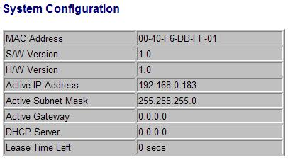
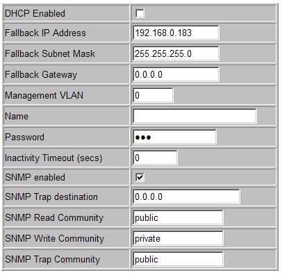
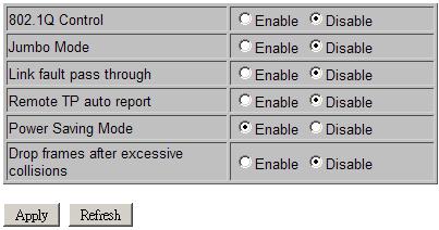
34 Configuration Description MAC Address The MAC address factory configured for the switch. It can not be changed in any cases. S/W Version Firmware version currently running H/W Version Hardware version currently operating Active IP Address Current IP address for the switch management Active Subnet Mask Current subnet mask for IP address for the switch management Active Gateway Current gateway IP address for the switch management DHCP Server Current IP address of the DHCP server Lease Time Left The time left for the lease IP address currently used DHCP Enabled Use DHCP to get dynamic IP address configuration for the switch Fallback IP Address IP address used when DHCP mode is disabled Fallback Subnet Mask Subnet mask for IP address used when DHCP mode is not enabled Fallback Gateway Default gateway IP address used when DHCP mode is not enabled Management VLAN Set management VLAN ID Name *1 Set the system name for this switch unit Password Set new password Inactivity Timeout No user interaction timeout for web disconnection (Auto logout). Options: 0 - no timeout 60 ~ seconds SNMP enabled Enable SNMP agent SNMP Trap destination The IP address of the SNMP trap manager SNMP Read community SNMP community allowed for the SNMP [get] message SNMP Write community SNMP community allowed for the SNMP [set] message SNMP Trap community SNMP community used for the SNMP trap messages sent by the switch 802.1Q Control 802.1Q Control function main configuration Disable - all packets are allowed to pass with no 802.1Q control. Enable Q control mechanism is activated for the conversion. Jumbo Mode Enable / disable Jumbo mode to support jumbo packets Disable - support maximum packet size up to 1526 bytes Enable - support maximum packet size up to 9600 bytes Link fault pass through Enable / disable link fault pass through function Remote TP auto report Enable / disable remote TP port link status function Power Saving Mode Enable / disable port link down power saving mode Drop frame after excessive collision 34
35 Enable - A frame is discarded and counted as an excessive collision if 16 collisions occur for this frame. Disable Not discarded [Apply] [Refresh] Click to apply the configuration change Click to refresh current configuration Note: 1. It is suggested to give each switch unit a system name as an alternative unique identification beside IP address. 2. Setting change of DHCP mode takes effective in next boot-up. 35
36 Management VLAN Management VLAN settings allow administrator to access the device and perform the management over a dedicated VLAN. The following rules are applied with the Management VLAN: 1. If [Management VLAN] setting is VID=0, no limitation is applied in accessing the web management interface, but password authentication. 2. If [Management VLAN] setting is VID>0, the web (http) server only replies to the management hosts through the tagged packets with the embedded VID same as the configured [Management VLAN] setting. 3. The web (http) server can accept untagged or tagged management accessing packets. Reply to the web access host based on the following rule: Incoming web access packets Reply packets (Outgoing to the management host) Untagged packets None Tagged packets Packets tagged with configured management VLAN VID 4. The configured VID is always included in permitted VID list under 802.1Q VID Filtering function. Notes: No matter how management VLAN is configured, login password authentication is still required. 36
37 4.4.2 Ports Port Configuration Port Link Mode Function TP - Twisted-Pair copper port (also specified Port #1 in other pages) FX - Fiber port (also specified Port #2 in other pages) Port link status Speed and duplex status with green background - port is link on Down with red background - port is link down Select port operating mode Disabled - disable the port operation TP Mode Auto-negotiation Speed capability Duplex Auto Enable 10, 100, 1000M Full, Half Forced 10 Half Disable 10M Half Forced 10 Full Disable 10M Full Forced 100 Half Disable 100M Half Forced 100 Full Disable 100M Full 1000 Full Enable 1000M Full Flow Control [Apply] [Refresh] FX Mode Auto-negotiation Speed capability Duplex capability Auto: auto-detection for transceiver type and speed 1000 Full Enable 1000M Full Forced 100 Full Disable 100M Full Disable: Disable port operation Set port flow control function V - set to enable 802.3x pause flow control for ingress and egress Click to apply the configuration change Click to refresh current configuration 37

38 802.1Q Control Page when [802.1Q Filtering] function is disabled 38
![802.1Q Control Page when [802.1Q Filtering] function is enabled. The setting is Allowed VID or Rejected VID 802.](/docs-images/89/97777110/images/39-1.jpg "1Q Control Function Default Tag VID (PVID) Port VID, VID for Ingress Default Tag, also called PVID 1 ~ 4095 - decimal 12-bit VID value Default Tag - DEI CFI for Ingress Default Tag 0, 1-1-bit CFI")
39 802.1Q Control Page when [802.1Q Filtering] function is enabled. The setting is Allowed VID or Rejected VID 802.1Q Control Function Default Tag VID (PVID) Port VID, VID for Ingress Default Tag, also called PVID 1 ~ decimal 12-bit VID value Default Tag - DEI CFI for Ingress Default Tag 0, 1-1-bit CFI value Default Tag -PCP User priority for Ingress Default Tag 0 ~ 7 - decimal 3-bit value Ingress Drop Disable - disable port ingress drop and admit all packet types Drop Untag drop all untagged frames Drop C-tag drop frame with outer tag TPID 0x8100 Drop S-tag drop frame with outer tag TPID 0x88A8 Drop All taggged drop frames with outer tag TPID 0x8100 or 0x88A8 Tag Removal Keep All tags - disable tag removal for VLAN-tagged packets 39
40 Pop up 1 tag remove up to 1 tag (outer tag if available) Pop up 2 tag remove up to 2 tags (outer and inner tag if available) Egress Tagging Rule Tag is inserted into the outgoing packet in egress operation. Type 0 Port Egress Tagging disabled Type 1 Tag all frames Type 2 Tag all frames, except priority-tagged frames (VID=0) and frame with VID= Exceptional VID Type 3 Tag all frames, except priority-tagged frames (VID=0) * Type 2 and Type 3 are available only when 802.1Q Filtering is enabled. Tagging Exceptional VID (Type 2) Type 1 exceptional VID in Tagging rule 1 ~ decimal 12-bit VID value * This configuration is available only when 802.1Q Filtering is enabled. Egress Tag TPID Tag TPID for Egress Tagging 0x8100(c-tag) 0x88A8(s-tag) s-custom_tag 1 Use value configured in [Custom TPID] s-custom_tag 2 - Use value configured in [Custom TPID] if ingress tag was s-tag (TPID = 0x88A8) * s-custom-tag 2 is available only when 802.1Q Filtering is enabled. Custom TPID Specify a user-defined TPID value. [802.1Q Filtering] Click to set VID filtering table Note: Refer to Section 3.5 and for more information about: 802.1Q Control, VLAN operation, Ingress VLAN Classification, Classified Tag after VLAN classification and What tag is inserted for egress tagging. Section also describes the VLAN mode under different [802.1Q Filtering] settings. 40
![4.4.2.1 802.1Q Filtering Configuration VID TABLE No. VID [Apply] [Refresh] [Back] Description Specify the characteristic of the VID table. Disable - set to disable 802.1Q filtering function.](/docs-images/89/97777110/images/41-0.jpg "Allowed VID - the VID table specifies the allowed VIDs rejected VID - the VID table specifies the rejected VIDs * Both Allowed VID and rejected VID are used to Enable 802.1Q filtering.")
41 Q Filtering Configuration VID TABLE No. VID [Apply] [Refresh] [Back] Description Specify the characteristic of the VID table. Disable - set to disable 802.1Q filtering function. Allowed VID - the VID table specifies the allowed VIDs rejected VID - the VID table specifies the rejected VIDs * Both Allowed VID and rejected VID are used to Enable 802.1Q filtering. Entry of VID table - up to 16 VIDs can be configured in VID table 1 ~ decimal 12-bit VID value Click to apply the configuration change. Click to refresh current configuration. Click to previous window. As VID TABLE setting is changed from Disable to enabled state. That is a setting of either Allowed VID or Rejected VID. The following message is prompt for notices and confirmation. 41

42 When VID TABLE setting is changed from either Allowed VID or Rejected VID to Disable, the following message is also prompt for notices and confirmation. Notes: 1. VID table is referred for filtering VLAN-tagged frames according to the classified VID of each ingress frame. Refer to Section for more information about classified VID and VLAN operation. 2. [Allowed VID] setting is useful when only certain VIDs are permitted to pass the device. 3. [Rejected VID] setting is useful when only certain VIDs are not allowed to pass the device. 4. The VID value in [Management VLAN] setting and [Default Tag VID (PVID)] for TP port and FX port are always permitted to pass and not be filtered. 42

43 4.4.3 LLDP Transmitted TLVs Port Description System Name System Description System Capability Management Address Parameters Tx Interval Description When checked the port description is included in LLDP information transmitted. When checked the system name is included in LLDP information transmitted. When checked the system description is included in LLDP information transmitted. When checked the system capability is included in LLDP information transmitted. When checked the management address is included in LLDP information transmitted. Description The switch is periodically transmitting LLDP frames to its neighbors for having the network discovery information up-to-date. The interval between 43
44 Tx Hold Tx Delay Reinit Delay Port Configuration Port LLDP State [Apply] [Refresh] each LLDP frame is determined by the Tx Interval value. Valid values: seconds Each LLDP frame contains information about how long the information in the LLDP frame shall be considered valid. The LLDP information valid period is set to Tx Hold multiplied by Tx Interval seconds. Valid values: 2 10 times If some configuration is changed (e.g. the IP address) a new LLDP frame is transmitted, but the time between the LLDP frames will always be at least the value of Tx Delay seconds. Tx Delay cannot be larger than 1/4 of the Tx Interval value. Valid values: seconds When a port is disabled, LLDP is disabled or the switch is rebooted a LLDP shutdown frame is transmitted to the neighboring units, signaling that the LLDP information isn t valid anymore. Reinit Delay controls the amount of seconds between the shutdown frame and a new LLDP initialization. Valid values: 1 10 seconds Description Local port number (Port #1: TP port, Port #2: FX port) Set port LLDP mode: Disabled: The switch will not send out LLDP information, and will drop LLDP information received from neighbors. Tx and Rx: The switch will send out LLDP information, and will analyze LLDP information received from neighbors. Tx only: The switch will drop LLDP information received from neighbors, but will send out LLDP information. Rx only: The switch will not send out LLDP information, but LLDP information from neighbor units is analyzed. Click to apply the configuration change. Click to refresh current configuration. The Link Layer Discovery Protocol (LLDP) is a vendor-neutral link layer protocol in the Internet Protocol Suite used by network devices for advertising their identity, capabilities, and neighbors on an IEEE 802 local area network, principally wired Ethernet. 44
![4.5 Monitoring 4.5.1 Statistics Overview Statistics Port Link Tx Bytes Tx Frames Rx Bytes Rx Frames Tx Errors Rx Errors [Clear] [Refresh] Description TP - Twisted-Pair copper port on local unit FX -](/docs-images/89/97777110/images/45-0.jpg "Fiber port on local unit Remote TP - TP port of the remote unit connected on the fiber link Port link status Speed and duplex status with green background - port is link on Down with red background -")
45 4.5 Monitoring Statistics Overview Statistics Port Link Tx Bytes Tx Frames Rx Bytes Rx Frames Tx Errors Rx Errors [Clear] [Refresh] Description TP - Twisted-Pair copper port on local unit FX - Fiber port on local unit Remote TP - TP port of the remote unit connected on the fiber link Port link status Speed and duplex status with green background - port is link on Down with red background - port is link down Total of bytes transmitted on the port Total of packet frames transmitted on the port Total of bytes received on the port Total of packet frames received on the port Total of error packet frames transmitted on the port Total of error packet frames received on the port Click to reset all statistic counters Click to refresh all statistic counters 45
 The number of LLDP frames transmitted on the port.")
46 4.5.2 LLDP Statistics Counters Port Tx Frames Rx Frames Rx Error Frames Discarde Frames TLVs discarded TLVs unrecognized Org. TLVs discarded Ageouts [Refresh] Description The port on which LLDP frames are received or transmitted. (Port #1: TP port, Port #2: FX port) The number of LLDP frames transmitted on the port. The number of LLDP frames received on the port. The number of received LLDP frames containing error. If an LLDP frame is received on a port, and the device's internal table has run full, the LLDP frame is counted and discarded. This situation is known as "Too Many Neighbours" in the LLDP standard. LLDP frames require a new entry in the table when the Chassis ID or Remote Port ID is not already contained within the table. Entries are removed from the table when a given port's link is down, an LLDP shutdown frame is received, or when the entry ages out. Each LLDP frame can contain multiple pieces of information, known as TLVs (TLV is short for "Type Length Value"). If a TLV is malformed, it is counted and discarded. The number of well-formed TLVs, but with an unknown type value. The number of organizationally received TLVs. Each LLDP frame contains information about how long time the LLDP information is valid (age-out time). If no new LLDP frame is received within the age out time, the LLDP information is removed, and the Ageout counter is incremented. Click to refresh all statistic counters 46
![4.5.3 LLDP Table Status Local Port Chassis Id Remote Port ID System Name Port Description System Capabilities Management Address [Refresh] Description The port on which the LLDP frame was received.](/docs-images/89/97777110/images/47-0.jpg "(Port #1: TP port, Port #2: FX port) The Chassis Id is the identification of the neighbor's LLDP frames.")
47 4.5.3 LLDP Table Status Local Port Chassis Id Remote Port ID System Name Port Description System Capabilities Management Address [Refresh] Description The port on which the LLDP frame was received. (Port #1: TP port, Port #2: FX port) The Chassis Id is the identification of the neighbor's LLDP frames. Port ID of the neighbor port System Name advertised by the neighbor unit The port description advertised by the neighbor unit System Capabilities describes the neighbor unit's capabilities. The possible capabilities are: 1. Other 2. Repeater 3. Bridge 4. WLAN Access Point 5. Router 6. Telephone 7. DOCSIS cable device 8. Station only 9. Reserved When a capability is enabled, the capability is followed by (+). If the capability is disabled, the capability is followed by (-). Management Address is the neighbor unit's address that is used for higher layer entities to assist discovery by the network management. This could for instance hold the neighbor's IP address. Click to refresh all statistic counters 47
![4.5.4 Ping Ping Target IP Address Count Time Out (in secs) [Apply] Results Description The target IP address to which the ping command issues The number of ping commands generated The time out for a](/docs-images/89/97777110/images/48-0.jpg "reply (in seconds) Start the ping command Description Target IP Address The target IP address to which the ping command issues Status The command status Received replies The number of replies")
48 4.5.4 Ping Ping Target IP Address Count Time Out (in secs) [Apply] Results Description The target IP address to which the ping command issues The number of ping commands generated The time out for a reply (in seconds) Start the ping command Description Target IP Address The target IP address to which the ping command issues Status The command status Received replies The number of replies received by the system Request time-outs The number of requests time out Average Response Time The average response time of a ping request (in mini-seconds) [Refresh] Click to refresh all statistic counters 48
49 4.6 Maintenance Loop-back Test This menu is used to start a loop-back test operation with the link partner unit over the fiber link. The message displayed during test is: The result message displayed after a test finished is: The test result is also displayed on LEDs - LBT and LBR Reboot System This menu is used to reboot the device unit remotely with current configuration. Starting this menu will make your current http connection lost. You must rebuild the connection to perform any management operation to the unit. 49

50 4.6.3 Restore Default This menu is used to restore all settings of the device unit with factory default values except current IP configuration and Management VLAN configuration Update Firmware This menu is used to perform in-band firmware (software) upgrade. Enter the path and file name of new firmware image file for uploading. Configuration Filename [Browse] [Upload] Description Path and filename (warp format) Click to browse your computer file system for the firmware image file Click to start upload 50
![4.6.5 Configuration File Transfer This [download] command can be used to backup current device configuration and download it to the connected management PC. The default filename is cfgdownload.](/docs-images/89/97777110/images/51-1.jpg "Configuration Filename [Browse] [Upload] [Download] Description Path and filename of a backup configuration file to be uploaded Click to browse your computer file system for the configuration file")
51 4.6.5 Configuration File Transfer This [download] command can be used to backup current device configuration and download it to the connected management PC. The default filename is cfgdownload. Configuration Filename [Browse] [Upload] [Download] Description Path and filename of a backup configuration file to be uploaded Click to browse your computer file system for the configuration file Click to start upload operation from the connected PC to the switch Click to start download operation from the switch to the connected PC Logout This menu is used to perform a logout from the web management immediately and return a login prompt. If current user does not perform any management operation over 3 minutes, the device will execute an auto logout and abort the current connection. 51
52 5. SNMP Support SNMP version support Managed Objects RFC SNMP Trap Support Snmp v1, v2c management MIB-II system OBJECT IDENTIFIER ::= { mib-2 1 } interfaces OBJECT IDENTIFIER ::= { mib-2 2 } ip OBJECT IDENTIFIER ::= { mib-2 4 } snmp OBJECT IDENTIFIER ::= { mib-2 11 } ifmib OBJECT IDENTIFIER ::= { mib-2 31 } RFC Management Information Base (MIB) for the Simple Network Management Protocol (SNMP) RFC Management Information Base for Network Management of TCP/IP-based internets:mib-ii RFC Management Information Base for network management of TCP/IP-based internets: MIB-II TRAP_COLDSTART - the device boot up trap TRAP_LINKUP - the port link recovery trap TRAP_LINKDOWN - port link down trap 52
53 Appendix A. Factory Default Settings System Configuration DHCP Enabled Disable Fallback IP Address Fallback Subnet Mask Fallback Gateway Management VLAN 0 Name Null Password 123 Inactivity Timeout (secs) 300 SNMP enabled Disable SNMP Trap destination SNMP Read Community public SNMP Write Community private SNMP Trap Community public 802.1Q Control Disable Jumbo Mode Disable Link fault pass through Disable Remote TP auto report Disable Power Saving Mode Enable Drop frames after excessive collisions Disable Ports Configuration Mode Auto for TP port, 1000 Full for FX port Flow Control v: Enable Default Tag - VID(PVID) 1 Default Tag DEI 0 Default Tag PCP 0 Ingress Drop Disable Tag Removal Keep All Tags Egress Tagging Rule Type 0 53
54 Tagging Exceptional VID 1 Egress Tag TPID Custom TPID 0x8100(c-tag) 0x Q Filtering VID TABLE Disable VID n (n=1-16) 0 LLDP Configuration Transmitted TLVs Port Description System Name System Description System Capabilities Management Address Enable Enable Enable Enable Enable LLDP Parameters Tx Interval 10 Tx Hold 4 Tx Delay 2 Reinit Delay 2 LLDP Port Configuration LLDP State Disable 54
55 Appendix B. Models & Optical Specifications Model Definition KGC-310M-C Managed model with no pre-installed SFP transceiver KGC-310M-C-xxxx Managed model with pre-installed SFP transceiver SFP with 1000BASE-X fiber transceiver Model Ext. FiberCon. Reference Fiber Distance (Typ.) -SX 1000M LC Duplex MMF 500m -LX 1000M LC Duplex MMF 550m, SMF 10km -LX M LC Duplex SMF 20km -LX M LC Duplex SMF 30km -LX M LC Duplex SMF 50km -LX M LC Duplex SMF 70km Bi-directional WDM over single SMF -W M LC Simplex SMF 10km -W M LC Simplex SMF 10km -W M LC Simplex SMF 20km -W M LC Simplex SMF 20km -W M LC Simplex SMF 10km -W M LC Simplex SMF 10km -W3410S 1000M SC Simplex SMF 10km -W4310S 1000M SC Simplex SMF 10km Optical Specifications Model Ext. Wavelength Tx Power* 1 Rx Sen.* 2 Max.Rx* 3 -SX 850nm -9.5~ LX 1310nm -9.5~ LX nm -8~ LX nm -4~ LX nm -4~ LX nm 0~ Bi-Direction WDM over single SMF -W3510 T1310/R1550-9~ W5310 T1550/R1310-9~ W3520 T1310/R1550-8~ W5320 T1550/R1310-8~ W3410 T1310/R1550-9~ W4310 T1550/R1310-9~
KGC-310 / KGC-310M. Installation Guide. Web Smart Gigabit Ethernet Media Converter. F/W v1.03 up DOC
 KGC-310 / KGC-310M Web Smart Gigabit Ethernet Media Converter F/W v1.03 up Installation Guide DOC.111205-1- (C) 2005 KTI Networks Inc. All rights reserved. No part of this documentation may be reproduced
PoE Powered Gigabit Ethernet Media Converters 1000BASE-T TO 1000BASE-SX/LX. KGC-352 Series. Installation Guide
 PoE Powered Gigabit Ethernet Media Converters 1000BASE-T TO 1000BASE-SX/LX KGC-352 Series Installation Guide DOC.070820-KGC-352-1- (C) 2007 KTI Networks Inc. All rights reserved. No part of this documentation
Industrial 5-Port Fast Ethernet Switches with SFP Slot and optional 4 PoE PSE Ports. Basic Model: KSD-541 PoE Model: KSD-541-P. Installation Guide
 Industrial 5-Port Fast Ethernet Switches with SFP Slot and optional 4 PoE PSE Ports Basic Model: KSD-541 PoE Model: KSD-541-P Installation Guide DOC.080104-1- (C) 2008 KTI Networks Inc. All rights reserved.
Industrial 5-Port Fast Ethernet Switches. with SFP Slot and optional 4 PoE PSE Ports. Basic Model: KSD-541. PoE Model: KSD-541-HP. Installation Guide
 Industrial 5-Port Fast Ethernet Switches with SFP Slot and optional 4 PoE PSE Ports Basic Model: KSD-541 PoE Model: KSD-541-HP Installation Guide DOC.141201-1- (C) 2014 KTI Networks Inc. All rights reserved.
INDUSTRIAL 1000BASE-T TO 1000BASE-X MEDIA CONVERTERS. KCD-400 Series. Installation Guide
 INDUSTRIAL 1000BASE-T TO 1000BASE-X MEDIA CONVERTERS KCD-400 Series Installation Guide DOC.060227-KCD-400-1- (C) 2005 KTI Networks Inc. All rights reserved. No part of this documentation may be reproduced
PoE Powered 10/100BASE-TX to 100BASE-FX Media Converters. KC-351 Series. Installation Guide
 PoE Powered 10/100BASE-TX to 100BASE-FX Media Converters KC-351 Series Installation Guide -1- DOC.070820-KC-351 (C) 2007 KTI Networks Inc. All rights reserved. No part of this documentation may be reproduced
KFC-200. Installation Guide
 KFC-200 10/100BASE-TX to 100BASE-FX Media Converters Installation Guide DOC.121221-1- (C) 2011-2012 KTI Networks Inc. All rights reserved. No part of this documentation may be reproduced in any form or
KSD-800 Series. Installation Guide. Industrial 8-Port Fast Ethernet Switches with Fiber Connectivity DOC A -1-
 KSD-800 Series Industrial 8-Port Fast Ethernet Switches with Fiber Connectivity Installation Guide DOC.110516A -1- (C) 2005 KTI Networks Inc. All rights reserved. No part of this documentation may be reproduced
Industrial 3-Port Fast Ethernet Media Converter Switches
 Industrial 3-Port Fast Ethernet Media Converter Switches KSD-103-A series KSD-103-B series Installation Guide DOC.081111 1/20 (C) 2008 KTI Networks Inc. All rights reserved. No part of this documentation
KGS-510F Web Smart 6-Port Gigabit Ethernet Switch with Fiber Connectivity Installation Guide
 KGS-510F Web Smart 6-Port Gigabit Ethernet Switch with Fiber Connectivity Installation Guide DOC.060118-1- (C) 2005 KTI Networks Inc. All rights reserved. No part of this documentation may be reproduced
10/100BASE-TX TO 100BASE-FX MEDIA CONVERTERS. KC-300DM Series. Installation Guide
 10/100BASE-TX TO 100BASE-FX MEDIA CONVERTERS KC-300DM Series Installation Guide -1- DOC.060215-KC-300D (C) 2003 KTI Networks Inc. All rights reserved. No part of this documentation may be reproduced in
10/100BASE-TX TO 100BASE-FX MEDIA CONVERTERS
 10/100BASE-TX TO 100BASE-FX MEDIA CONVERTERS KC-300DM Series Installation Guide DOC.130923-1- (C) 2003-2013 KTI Networks Inc. All rights reserved. No part of this documentation may be reproduced in any
10/100BASE-TX TO 100BASE-FX MEDIA CONVERTERS EM4000 EM4001. Installation Guide
 10/100BASE-TX TO 100BASE-FX MEDIA CONVERTERS EM4000 EM4001 Installation Guide DOC.050523-EM400X -1- The information contained in this document is subject to change without prior notice. Copyright (C) All
KGD-600 Industrial Web Smart 6-Port Gigabit Ethernet Switch with Fiber Connectivity Installation Guide
 KGD-600 Industrial Web Smart 6-Port Gigabit Ethernet Switch with Fiber Connectivity Installation Guide DOC.100119-1- (C) 2006 KTI Networks Inc. All rights reserved. No part of this documentation may be
Installation Guide. Web Smart Managed 10/100 Fast Ethernet Switches with VLAN Support
 Installation Guide Web Smart Managed 10/100 Fast Ethernet Switches with VLAN Support KS-115FM-V KS-117FM-V DOC.060510-1- (C) 2006 KTI Networks Inc. All rights reserved. No part of this documentation may
M727xS 10/100BaseTX-FX Selectable Media Converter Installation Guide
 M727xS 10/100BaseTX-FX Selectable Media Converter Installation Guide Copyright January 2004 VERSITRON, Inc. 83 Albe Drive / Suite C Newark, DE 19702 A010430357 The information contained in this document
KGD-600-B Industrial Web Smart 6-Port Gigabit Ethernet Switch with Fiber Connectivity Installation Guide
 KGD-600-B Industrial Web Smart 6-Port Gigabit Ethernet Switch with Fiber Connectivity Installation Guide DOC.120606-1- (C) 2012 KTI Networks Inc. All rights reserved. No part of this documentation may
M727xSP. PoE Powered. Ethernet Media Converter 10/100BASE-TX TO 100BASE-SX/LX. Installation Guide
 M727xSP PoE Powered Ethernet Media Converter 10/100BASE-TX TO 100BASE-SX/LX Installation Guide September 2009 VERSITRON, Inc. 83 Albe Drive - Suite C Newark, DE 19702 www.versitron.com www.versitron.com
Modular 8-Port Mid-span Power over Ethernet Injector
 Modular 8-Port Mid-span Power over Ethernet Injector KPOE-800-1P KPOE-800-2P Installation Guide DOC.090201 1 (C) 2008 KTI Networks Inc. All rights reserved. No part of this documentation may be reproduced
Industrial Serial RS-232 to Fiber Converter. KSC-200 Series. Installation Guide
 Industrial Serial RS-232 to Fiber Converter KSC-200 Series Installation Guide DOC.100803-KSC-200-1- (C) 2006 KTI Networks Inc. All rights reserved. No part of this documentation may be reproduced in any
MF BASE-T to 1000BASE-X INDUSTRIAL MEDIA CONVERTER WITH SFP SUPPORT INSTALLATION GUIDE
 1000BASE-T to 1000BASE-X INDUSTRIAL MEDIA CONVERTER WITH SFP SUPPORT INSTALLATION GUIDE September 2006 VERSITRON, Inc. 83 Albe Drive - Suite C Newark, DE 19702 2 PROPRIETARY DATA All data in this manual
MF727xS INDUSTRIAL 10/100BASE-TX TO 100BASE-FX MEDIA CONVERTER. Installation Guide
 1 INDUSTRIAL 10/100BASE-TX TO 100BASE-FX MEDIA CONVERTER Installation Guide October 2008 VERSITRON, Inc. 83C Albe Drive Newark, DE 19702 800-537-2296 2 PROPRIETARY DATA All data in this manual is proprietary
S7055xM / S7075xM Web Smart Managed 5-Port / 7-Port 10/100 Fast Ethernet Switch w/vlan Support Installation Guide
 S7055xM / S7075xM Web Smart Managed 5-Port / 7-Port 10/100 Fast Ethernet Switch w/vlan Support Installation Guide January 2005 VERSITRON, Inc. 83 Albe Drive / Suite C Newark, DE 19702 A050130380 The information
KSD-800M Industrial Managed 8-Port Fast Ethernet Switches with Fiber Connectivity Operation Manual
 KSD-800M Industrial Managed 8-Port Fast Ethernet Switches with Fiber Connectivity Operation Manual for software v1.092 and later DOC.080604-1- (C) 2005 KTI Networks Inc. All rights reserved. No part of
KPW-T2P25. PoE Splitter. Industrial IEEE 802.3at High Power. User s Manual -1- DOC
 KPW-T2P25 Industrial IEEE 802.3at High Power PoE Splitter User s Manual DOC.121011-1- (C) 2012 KTI Networks Inc. All rights reserved. No part of this documentation may be reproduced in any form or by any
SF7085xM. 8-Port 10/100 Industrial Managed Switch. Operation Manual. Rev. B
 1 8-Port 10/100 Industrial Managed Switch Operation Manual Rev. B May 2009 VERSITRON, Inc. 83 Albe Drive / Suite C Newark, DE 19702 The information contained in this document is subject to change without
Mid-span 802.3af PoE Injector. Installation Guide KPOE-100
 Mid-span 802.3af PoE Injector Installation Guide KPOE-100 Doc. 070521 1 (C) 2005 KTI Networks Inc. All rights reserved. No part of this documentation may be reproduced in any form or by any means or used
HES-3109 SERIES 9 PORTS 10/100/1000BASE-T MANAGEMENT ETHERNET SWITCH
 HES-3109 SERIES 9 PORTS 10/100/1000BASE-T MANAGEMENT ETHERNET SWITCH 8 PORTS 10/100/1000BASE-T MANAGEMENT ETHERNET SWITCH WITH 1 PORT 1000BASE-X UPLINK OR 1 PORT 100/1000BASE-X UPLINK 8 PORTS 10/100/1000BASE-T
KGS-2421 Managed 24-Port Gigabit Ethernet Switches with 4 SFP Slots
 KGS-2421 Managed 24-Port Gigabit Ethernet Switches with 4 SFP Slots Installation Guide DOC.121213-1- (C) 2010-2012 KTI Networks Inc. All rights reserved. No part of this documentation may be reproduced
HES-3106-PLUS SERIES
 HES-3106-PLUS SERIES 5 PORTS 10/100/1000BASE-T ETHERNET MANAGED SWITCH WITH 1 PORT 1000BASE-X or 100/1000BASE-X UPLINK User s Guide Version 0.92 Trademarks CTS is a registered trademark of Connection Technology
Hardened Web-Smart High Power PoE Ethernet Switch
 Quick Start Guide This quick start guide describes how to install and use the Hardened Web-Smart High Power PoE (Power over Ethernet) Ethernet Switch. This is the switch of choice for harsh environments
SF70860M & SF70860MP 8-Port 10/100/1000 Industrial Managed Switch With PoE Support
 SF70860M & SF70860MP 8-Port 10/100/1000 Industrial Managed Switch With PoE Support Operation Manual Rev. B March 2010 VERSITRON, Inc. 83 Albe Drive / Suite C Newark, DE 19702 www.versitron.com www.versitron.com
GVM-1101 / GVM-1220 / GVM-1000 Web Smart Media Converter
 GVM-1101 / GVM-1220 / GVM-1000 Web Smart Media Converter User Manual Chapter 1 Overview 1.1 Overview GVM-1101 / GVM-1220 / GVM-1000 is remote Managed 10/100/1000 auto-negotiation Ethernet fiber media converter
Quick Start Guide. Physical Description. The Port Status LEDs
 Quick Start Guide This quick start guide describes how to install and use the Hardened PoE Ethernet Switch. Capable of operating at temperature extremes of -40 C to +75 C, this is the switch of choice
FWRIII-2105 SERIES. 4 ports 10/100Mbps RJ-45; built-in IEEE802.11n WiFi and 1 port 100Mbps SFP slot uplink Residential Gateway. Residential Gateway
 FWRIII-2105 SERIES 4 ports 10/100Mbps RJ-45; built-in IEEE802.11n WiFi and 1 port 100Mbps SFP slot uplink Residential Gateway 4 ports 10/100Mbps RJ-45; built-in IEEE802.11n WiFi and 1 port 100Mbps SFP
FRG-3105 Series Residential Gateway
 FRG-3105 Series Residential Gateway User s Guide Version 0.90 Revision History Version Date Description 0.90 20170605 First Release 2 Trademarks Contents are subject to revision without prior notice. All
Hardened Web-Smart PoE & High Power PoE Ethernet Switch
 Quick Start Guide This quick start guide describes how to install and use the Hardened Web-Smart PoE (Power over Ethernet) and High Power PoE Ethernet Switch. This is the switch of choice for harsh environments
Preface. Managed Media Converter Chassis System
 Preface The Managed Media Converter Chassis System supports the Media Converter Chassis to monitor the each Media Converter ( CO ) or Chassis Manager status and to configure advanced function of the Managed
LevelOne GES GE with 1 Combo SFP Web Smart Switch User Manual
 LevelOne GES-0852 8 GE with 1 Combo SFP Web Smart Switch User Manual Version 1.0-1109 1 FCC Certifications This Equipment has been tested and found to comply with the limits for a Class A digital device,
MS400870M. User's Guide. Ver.: Port GBE SFP Switch 19 1U 24x10/100/1000T Combo 10/1000X SFP
 MS400870M 24 Port GBE SFP Switch 19 1U 24x10/100/1000T Combo 10/1000X SFP User's Guide. Ver.:0.91 1 CE Mark Warning This is a Class A product. In a domestic environment, this product may cause radio interference
10/100/1000T to Mini-GBIC Industrial Switch Converter 10/100/1000T to 1000SX/LX Industrial Switch Converter. AMG9011G-H (-40 to 75C) User Manual
 User Manual") 10/100/1000T to Mini-GBIC Industrial Switch Converter 10/100/1000T to 1000SX/LX Industrial Switch Converter AMG9011G-H (-40 to 75C) User Manual www.amgsystems.com Content Overview...1 Introduction... 1
10/100/1000T to Mini-GBIC Industrial Switch Converter 10/100/1000T to 1000SX/LX Industrial Switch Converter AMG9011G-H (-40 to 75C) User Manual www.amgsystems.com Content Overview...1 Introduction... 1
User s Manual. Management Converter Chassis. Model No.: SP1386 / SP1387. World Wide Web: ;
 User s Manual Management Converter Chassis Model No.: SP1386 / SP1387 World Wide Web: www.micronet.com.tw ; www.micronet.info Table of Content 1. INTRODUCTION... 2 1.1 PACKAGE CONTENT... 2 1.2 KEY FEATURES...
User s Manual IGT-902 / 902T IGT-902S / 902TS IGT-905A. 10/100/1000Base-T to 1000Base-SX / LX. Industrial Managed Media Converter
 User s Manual IGT-902 / 902T IGT-902S / 902TS IGT-905A 10/100/1000Base-T to 1000Base-SX / LX Industrial Managed Media Converter -1- Trademarks Copyright PLANET Technology Corp. 2010. Contents subject to
Ethernet Media Converter Web Smart Series. User Manual
 Ethernet Media Converter Web Smart Series User Manual v1.0 May. 2011 i Ethernet Media Converter Web Smart Series FVS-3800, 10/100BASE-TX to 100BASE-X SFP Converter FVS-3200, 10/100BASE-TX to 100BASE-FX
Industrial 10/100/1000BASE-T to 100/1000BASE-X SFP Media Converter
 Industrial 10/100/BASE-T to 100/BASE-X SFP Media Converter Physical Port 1-port 10/100/BASE-T RJ45 with auto MDI / MDI-X function 1 SFP interface, 100/BASE-X dual mode (auto detection) Layer 2 Features
8-port 10/100TX + 2-Port 10/100/1000T/100/1000 SFP Combo with 8 PoE Injectors Industrial Ethernet Switch User Manual
 8-port 10/100TX + 2-Port 10/100/1000T/100/1000 SFP Combo with 8 PoE Injectors Industrial Ethernet Switch User Manual FCC Warning This Equipment has been tested and found to comply with the limits for a
KGS-2422-B. Installation Guide. Managed 24-Port Modular Gigabit Ethernet. Switches with 100BASE-FX Support -1- DOC
 KGS-2422-B Managed 24-Port Modular Gigabit Ethernet Switches with 100BASE-FX Support Installation Guide DOC.150819-1- (C) 2015 KTI Networks Inc. All rights reserved. No part of this documentation may be
Industrial Gigabit Managed Ethernet Switch
 HMG-828 HMG-828E Industrial Gigabit Managed Ethernet Switch Features High Performance Network Switching Technology Complies with IEEE 802.3, IEEE 802.3u, IEEE 802.3X, IEEE 802.1p, IEEE 802.1q, IEEE 802.1d,
4 10/100/1000T Mini-GBIC with 4 IEEE 802.3at High Power PoE Industrial Wide Temperature Switch. User Manual SISTP LRT
 4 10/100/1000T + 2 1000 Mini-GBIC with 4 IEEE 802.3at High Power PoE Industrial Wide Temperature Switch User Manual V1.0 September-2013 FCC Warning This Equipment has been tested and found to comply with
Chassis-based Media Converters
 Media Converters with Individual Metal Case Housing. DMC-615SC DMC-1002 Management Module DMC-1000 Chassis Chassis-based Media Converters System Overview The Chassis-based Media Converters include a number
Installation Guide. 100BASE-TX/100BASE-FX Fast Ethernet Media Converter NC-200FT/FC. -1-iIiNC-200FT/FC P/N:
 Installation Guide 100BASE-TX/100BASE-FX Fast Ethernet Media Converter NC-200FT/FC -1-iIiNC-200FT/FC P/N:750-0166-001 Table le of Contents General Description...3 Specifications...4 Connectors & Cables...5
User's Manual FT-902 FT-902S15 FT-902S35 FT-902S50 FT-905A FT-906A20 / FT-906B20. 10/100Base-TX to 100Base-FX. Managed Media Converter
 User's Manual FT-902 FT-902S15 FT-902S35 FT-902S50 FT-905A FT-906A20 / FT-906B20 10/100Base-TX to 100Base-FX Managed Media Converter Trademarks Copyright PLANET Technology Corp. 2010. Contents subject
IES User Manual. 8 FE + 1 MM SC Unmanaged Switch -40 to 75, DIN-rail. v
 IES-0920 8 FE + 1 MM SC Unmanaged Switch -40 to 75, DIN-rail User Manual v1.00-1206 Preface This manual describes how to install and use the Industrial Ethernet Switch. This switch integrates full wire
Industrial 8-Port 10/100/1000T + 2-Port 100/1000X SFP Ethernet Switch (-40~75 degrees C)
") Industrial 8-Port 10/100/T + 2-Port 100/X SFP Ethernet Switch (-40~75 degrees C) Physical Port 8-port 10/100/BASE-T RJ45 with auto MDI/MDI-X function 2 SFP slots, supporting BASE-X and 100BASE-FX transceiver
Industrial 8-Port 10/100/T + 2-Port 100/X SFP Ethernet Switch (-40~75 degrees C) Physical Port 8-port 10/100/BASE-T RJ45 with auto MDI/MDI-X function 2 SFP slots, supporting BASE-X and 100BASE-FX transceiver
PHB-200M PHB x 100/1000Base-T to 20x 100/1000Base-X FE/GbE Media Converter Concentrator
 Media Converter Concentrator PHB-200M PHB-200 20x 100/1000Base-T to 20x 100/1000Base-X FE/GbE Media Converter Concentrator PHB-200M is a 20-channel Managed Media Converter that converts copper 100/1000Base-TX
Fast Ethernet Converter. User Guide MICROSENS
 Fast Ethernet Converter User Guide MICROSENS Rev.1.25 Jan-2010 Content Introduce... 1 Features... 2 Package Contents... 3 Hardware Description... 4 Front Panel... 4 Ports... 5 LED Indicators... 5 DIP-switch...
PHB-200M PHB x 100/1000Base-T to 20x 100/1000Base-X
 SFP Patching Hub PHB-200M PHB-200 20x 100/1000Base-T to 20x 100/1000Base-X SFP Patching Hub PHB-200M is a 20-channel Managed SFP patching hub that converts copper 100/1000Base-TX to SFPs working at 100Mbps
CTS-iCPE Gateway Controller User s Manual Version: Revision B1
 CTS-iCPE Gateway Controller User s Manual Version: Revision B1 Trademarks Contents are subject to revision without prior notice. All other trademarks remain the property of their respective owners. Copyright
FCN-3112 Series. 10/100/1000TX to 1000SX SNMP Managed Media Converter. Version 1.0 User Manual
 FCN-3112 Series 10/100/1000TX to 1000SX SNMP Managed Media Converter Version 1.0 User Manual Copyright 2018 Antaira Technologies, LLC. All Rights Reserved This document contains information, which is protected
Korenix JetNet 3000 Series Industrial Entry-Level Ethernet Rail Switch User s Manual
 Korenix JetNet 3000 Series Industrial Entry-Level Ethernet Rail Switch User s Manual Fourth Edition, DEC, 2007 www.korenix.com Korenix JetNet 3000 Series Industrial Entry-Level Ethernet Rail Switch User
Industrial Managed Ethernet Switch
 HME-823 HME-823E Industrial Managed Ethernet Switch Features High Performance Network Switching Technology Complies with IEEE 802.3, IEEE 802.3u, IEEE 802.3X, IEEE 802.1p, IEEE 802.1q, IEEE 802.1d, IEEE
Media Converters & Chassis
 Expandable Chassis System The Chassis-based Media Converter product lineup includes various independent media converters and a chassis capable of housing up to 16 media converters. You can start with a
IEC-0101FT Industrial 10/100TX to 100M-FX Slim Type Converter User Manual
 Lantech IEC-0101FT Industrial 10/100TX to 100M-FX Slim Type Converter User Manual FCC Warning This Equipment has been tested and found to comply with the limits for a Class A digital device, pursuant to
LNP-0602 series. 6-port Industrial PoE+ Unmanaged Ethernet Switches 4*10/100Tx (30W/Port) + 2*100Fx. User Manual
 + 2*100Fx. User Manual") LNP-0602 series 6-port Industrial PoE+ Unmanaged Ethernet Switches 4*10/100Tx (30W/Port) + 2*100Fx User Manual FCC Warning This Equipment has been tested and found to comply with the limits for a Class-A
LNP-0602 series 6-port Industrial PoE+ Unmanaged Ethernet Switches 4*10/100Tx (30W/Port) + 2*100Fx User Manual FCC Warning This Equipment has been tested and found to comply with the limits for a Class-A
Preface. Media Converter
 Preface This manual describes how to install and use the Ethernet Media Converter with the link-fault-pass-through function. The Converter introduced here provides one channel media conversion between
INSTRUCTION MANUAL FMX-GE-1000 ETHERNET TO OPTICAL MEDIA CONVERTER
 INSTRUCTION MANUAL FMX-GE-1000 ETHERNET TO OPTICAL MEDIA CONVERTER 191 FOREST AVENUE LOCUST VALLEY, NY 11560-2132 USA (800)-488-8378 / (516)-671-7278 FAX (516)-671-3362 sales@multidyne.com www.multidyne.com
A valid network connection established. Transmitting or receiving data. ACT stands for ACTIVITY.
 Quick Start Guide This quick start guide describes how to install and use the Hardened Web-Smart PoE (Power over Ethernet) Ethernet Switch. Port and LED number will vary on different models. This user's
Product names mentioned in this manual may be trademarks or registered trademarks of those products.
 FCC Statement The FCC (Federal Communications Commission) restricts the amount of radio frequency emission and radiation coming from computer equipment. The equipment introduced in this manual has been
1 10/100TX FX w/ 1 PoE Injector Industrial Switch. User Manual
 1 10/100TX + 1 100FX w/ 1 PoE Injector Industrial Switch User Manual CE Mark Warning This is a Class-A product. In a domestic environment this product may cause radio interference in which case the user
Chassis-based Media Converters
 Media Converters with Individual Metal Case Housing. DMC-615SC DMC-1002 Management Module DMC-1000 Chassis DMC-1530SC Chassis-based Media Converters System Overview The Chassis-based Media Converters include
IMC-21GA Quick Installation Guide
 IMC-21GA Quick Installation Guide Moxa Industrial Media Converter Edition 4.0, June 2017 Technical Support Contact Information www.moxa.com/support Moxa Americas: Toll-free: 1-888-669-2872 Tel: 1-714-528-6777
10/100TX to 100FX w/ 1 PoE Injector Industrial Media Converter User Manual
 10/100TX to 100FX w/ 1 PoE Injector Industrial Media Converter User Manual v1.02 FCC Warning This Equipment has been tested and found to comply with the limits for a Class-A digital device, pursuant to
IES User Manual. 6 GE + 2 SFP Unmanaged Switch -20 to 60C, DIN-rail. v
 IES-0823 6 GE + 2 SFP Unmanaged Switch -20 to 60C, DIN-rail User Manual v1.00-1206 Preface A member of the growing family of rugged switches, this switch addresses a need for a smaller switch. This switch
Industrial PoE Media Converter
 Quick Start Guide This quick start guide describes how to install and use the Industrial PoE Media Converter. This is the Media Converter of choice for harsh environments constrained by space. Physical
Chassis-based Media Converters
 Media Converters with Individual Metal Case Housing. DMC-615SC DMC-1002 Management Module DMC-1000 Chassis DMC-920 DMC-1530SC DMC-1580SC Chassis-based Media Converters System Overview The Chassis-based
Quick Start Guide Elinx ESW500 Series. Managed Din Rail Ethernet Switch
 Quick Start Guide Elinx ESW500 Series Managed Din Rail Ethernet Switch ESW500 Series Documentation Number: ESW500series-1012qsg International Headquarters: 707 Dayton Road Ottawa, IL 61350 USA Phone (815)
SWP-0208G, 8+2SFP. 8-Port Gigabit Web Smart Switch. User s Manual
 SWP-0208G 1 SWP-0208G, 8+2SFP 8-Port Gigabit Web Smart Switch User s Manual Version: 3.4 April 1, 2008 2 TABLE OF CONTENT 1.0 INTRODUCTION...4 1.1 MAIN FEATURES...4 1.2 START TO MANAGE THIS SWITCH...6
DW- SW-PoE-24M. wwww.denwaip.com
 DW- SW-PoE-24M w DW- SW-PoE-24M OVERVIEW The 24 -Port managed PoE Switch, with 24 100Mbit RJ45 ports,2 Gigabit SFP port and 2 Gigabit Uplink, model DW-SW-PoE-24M, reduces equipment and installation costs
imc2f Features Industrial IEC Ethernet to Fiber Media Converter Tel: Fax:
 imc2f www.is5com.com Industrial IEC 61850-3 Ethernet to Fiber Media Converter Features Fully compliant with the requirement of IEC 61850-3 and IEEE 1613 EN50155-compliant Ethernet switch for rolling stock
SWH-3112 Series 12-port L2+ Managed Gigabit Fiber Switch User s Guide
 SWH-3112 Series 12-port L2+ Managed Gigabit Fiber Switch User s Guide Version: 1.0 Revision History Version Date Changes 0.9 11/10/2017 First release 1.0 05/08/2018 Use the new template FCC Warning This
Installation Guide 24-port 10/100 Fast Ethernet Switch with 1 Fiber Connection Model Name: KS-324F
 Installation Guide 24-port 10/100 Fast Ethernet Switch with 1 Fiber Connection Model Name: KS-324F We make no warranties with respect to this documentation and disclaim any implied warranties of merchantability,
4-port 10/100TX + 1 or 2-port 100FX Industrial Switch. User Manual
 4-port 10/100TX + 1 or 2-port 100FX Industrial Switch User Manual Rev.1.03 Sep-2010 FCC Warning This Equipment has been tested and found to comply with the limits for a Class A digital device, pursuant
ProSAFE 8-Port 10-Gigabit Web Managed Switch Model XS708Ev2 User Manual
 ProSAFE 8-Port 10-Gigabit Web Managed Switch Model XS708Ev2 User Manual April 2016 202-11656-01 350 East Plumeria Drive San Jose, CA 95134 USA Support Thank you for purchasing this NETGEAR product. You
Lantech IPGC-0101DSFP. User Manual. 10/100/1000T (PoE at) to 100/1000M SFP Industrial Switch Converter
 to 100/1000M SFP Industrial Switch Converter") Lantech IGC-0101DSFP IPGC-0101DSFP 10/100/1000T (PoE at) to 100/1000M SFP Industrial Switch Converter User Manual Dec 2016 Recommendation for Shielded network cables STP cables have additional shielding
Lantech IGC-0101DSFP IPGC-0101DSFP 10/100/1000T (PoE at) to 100/1000M SFP Industrial Switch Converter User Manual Dec 2016 Recommendation for Shielded network cables STP cables have additional shielding
ProSAFE 8-Port and 16-Port 10-Gigabit Ethernet Web Managed Switch Models XS708Ev2 and XS716E User Manual
 ProSAFE 8-Port and 16-Port 10-Gigabit Ethernet Web Managed Switch Models XS708Ev2 and XS716E User Manual March 2017 202-11656-03 350 East Plumeria Drive San Jose, CA 95134 USA Support Thank you for purchasing
Manual. Preface. XSNet 3100MC
 Manual Preface This manual describes how to install and use the Ethernet Media Converter with the link-fault-pass-through function. The Converter introduced here provides one channel media conversion between
SD24GS. 24-Port Web Smart Gigabit Ethernet Switch. User s Manual
 SD24GS 24-Port Web Smart Gigabit Ethernet Switch User s Manual FCC Warning This equipment has been tested and found to comply with the limits for a Class A digital device, pursuant to Part 15 of the FCC
16-SLOT IN-BAND MANAGEMENT CHASSIS
 FCM-CHS2-XX 16-SLOT IN-BAND MANAGEMENT CHASSIS User's Guide. Version 1.6 FCC Warning This equipment has been tested and found to comply with the limits for a Class A digital device, pursuant to Part 15
Hardened PoE Ethernet Switch
 Quick Start Guide This quick start guide describes how to install and use the Hardened PoE Ethernet Switch. This is the switch of choice for harsh environments constrained by space. Physical Description
IPS-3110 Managed Industrial PoE Gigabit Ethernet Switch
 IPS-3110 Managed Industrial PoE Gigabit Ethernet Switch User s Guide Version 0.90 Trademarks Contents are subject to revision without prior notice. All other trademarks remain the property of their respective
10/100M Ethernet Media Converter.
 Media Converter 10/100M 10/100M Ethernet Media Converter. Product introduction 10/100M Fast Ethernet Media Converter, relies on its unique function of optical-electricity LFA (Link Failure Alert) to realize
Gigabit Ethernet Media Converter
 Quick Start Guide This quick start guide describes how to install and use the Gigabit Ethernet media converter. The converter introduced here provides one channel media conversion solution. Physical Description
PHB-200M/PHB x 100/1000Base-T to 20x100/1000Base-X SFP Patching Hub
 SFP Patching Hub PHB-200M/PHB-200 20x 100/1000Base-T to 20x100/1000Base-X SFP Patching Hub PHB-200M is a 20-channel Managed SFP patching hub that converts copper 100/1000Base-TX to SFPs working at 100Mbps
Industrial Switches Industrial Switches
 Industrial Switches Industrial Switches Copper cables Fiber optic cable Ring redundancy Industrial Switches Contents 23 General Product Information 2 Interfaces and Configurations 2 Application and Installation
Lantech. IPGS-0204DSFP 4 10/100/1000T PoE at/af + 2 Dual Speed SFP Industrial Unmanaged Switch
 Lantech IPGS-0204DSFP 4 10/100/1000T PoE at/af + 2 Dual Speed SFP Industrial Unmanaged Switch IGS-0204DSFP 4 10/100/1000T + 2 Dual Speed SFP Industrial Unmanaged Switch User Manual V1.00 Jul-2016 Content
User Manual. GSS Series 16/24 Port Gigabit Web Managed Switch (GSS-16T4SFP & GSS-24T4SFP) Version 1.0 Sep. 2007
 Version 1.0 Sep. 2007") User Manual GSS Series 16/24 Port Gigabit Web Managed Switch (GSS-16T4SFP & GSS-24T4SFP) Version 1.0 Sep. 2007 1 Table of Contents CAUTION...3 ELECTRONIC EMISSION NOTICES...3 ABOUT THIS USER MANUAL...4
User Manual GSS Series 16/24 Port Gigabit Web Managed Switch (GSS-16T4SFP & GSS-24T4SFP) Version 1.0 Sep. 2007 1 Table of Contents CAUTION...3 ELECTRONIC EMISSION NOTICES...3 ABOUT THIS USER MANUAL...4
24-Port 10/100Mbps with 2-Gigabit Web Smart Ethernet Switch
 User's Manual FGSW-2402VS FGSW-2620VSF FGSW-2624SF 24-Port 10/100Mbps with 2-Gigabit Web Smart Ethernet Switch - 1 - Trademarks Copyright PLANET Technology Corp. 2006. Contents subject to revision without
CVT-2512 SERIES CVT-3512 SERIES
 CVT-2512 SERIES 10/100BASE-TX to 100BASE-FX Standalone Managed Media Converter with 802.3ah OAM compliance CVT-3512 SERIES 10/100/1000BASE-T to 1000BASE-X Standalone Managed Media Converter with 802.3ah
Device Server for the conversion of serial interfaces (RS-232/422/485) to IP.
 to IP.") Manual Entry Line Industrial Gigabit Ethernet Switch 4x 10/100/1000Base-T, 1x SFP Ports MICROSENS General The IP protocol has already left the in-house environment and is going to take all remaining communication
Manual Entry Line Industrial Gigabit Ethernet Switch 4x 10/100/1000Base-T, 1x SFP Ports MICROSENS General The IP protocol has already left the in-house environment and is going to take all remaining communication
10/100/1000Mbps. Gigabit Ethernet Switch GSW-2401/GSW User's Manual
 10/100/1000Mbps Gigabit Ethernet Switch GSW-2401/GSW-1601 User's Manual Trademarks Copyright PLANET Technology Corp. 2005. Content subjects to revision without prior notice. PLANET is a registered trademark