Steltronic Universal LCD Mounting Bracket Assembly
|
|
|
- Amie Patricia Floyd
- 5 years ago
- Views:
Transcription


1 Steltronic Universal LCD Mounting Bracket Assembly

 B.")
 C.")
 D.")
2 Components necessary to build the bracket assembly A. Main Plate (1 required per pair of monitors) B. Slide Rails (2 required per pair of monitors) C. Monitor Plate (2 required per pair of monitors) D. Channel Assembly (2 required per pair of monitors) E. Hanger Bracket (2 required per pair of monitors)


3 F. Shelf Plate (1 per pair of monitors) Note: This shelf plate is only necessary when installing the Vision Lane Computers, as the Elex and Super Elex have different mounting systems G. VLC Mounting Plate (2 required per pair of lanes, and you should have one left and one right side) Note: This mounting plate is only necessary when installing the Vision Lane Computers, as the Elex and Super Elex have different mounting systems

4 Assembly instructions for the Steltronic Universal LCD Mounting Bracket Assembly of the Steltronic universal bracket assembly is not difficult, but there are a few tips below that will help you assemble this bracket assembly correctly the first time without the need to go back and make fine tuning type adjustments. Step 1: Locate the 3 holes in the bottom of part A as shown below. It is necessary to establish the bottom of this part A. As shown above, the image you are looking at is a completed monitor frame with LCD monitors and the VLC resting on part F, the shelf plate for the VLC. Mount the small metal plate (Part F ) to the bottom of this plate (Part A ). This small plate acts as a type of shelf where the Vision Lane Computer (VLC) can sit comfortably as you mount the VLC to this frame.

 main plate.")
 can slide from side to side on the slide")
5 Step 3: Mount the long slide rails (part B ) to the plate (Part A ), and when you do this, the rails get bolted to the front side of this plate. Take note of how the plate is resting in the image below, because you need to mount the slide rails to the front side of the (part A ) main plate. These slide rails (Part B ) will be able to hold the monitor plate (Part C ) and the monitor plate (Part C ) can slide from side to side on the slide rails (Part B )


6 Step 4: Mount the monitor plates (Part C ) to the back side of the LCD monitors. When you do this, it s important to keep all of these plates mounted on each monitor in the exact same way for each monitor. We suggest keeping the monitor plate (Part C ) loose on the monitor, then pushing this plate down towards the bottom side of the monitor, and then to the far left of the monitor before you tighten the hardware. This assures the plate is in the same location on each monitor and you will have uniformity across all monitors on all of your frame assemblies. Also take note of the red circles below, these hooks need to be pointed DOWN towards the bottom of the monitor You can also insert the 2 screws into the bottom of this plate now (easier to do now, than later on the ladder!)
 that you can use for adhering to the existing chain and/or cables coming out of your ceiling.")

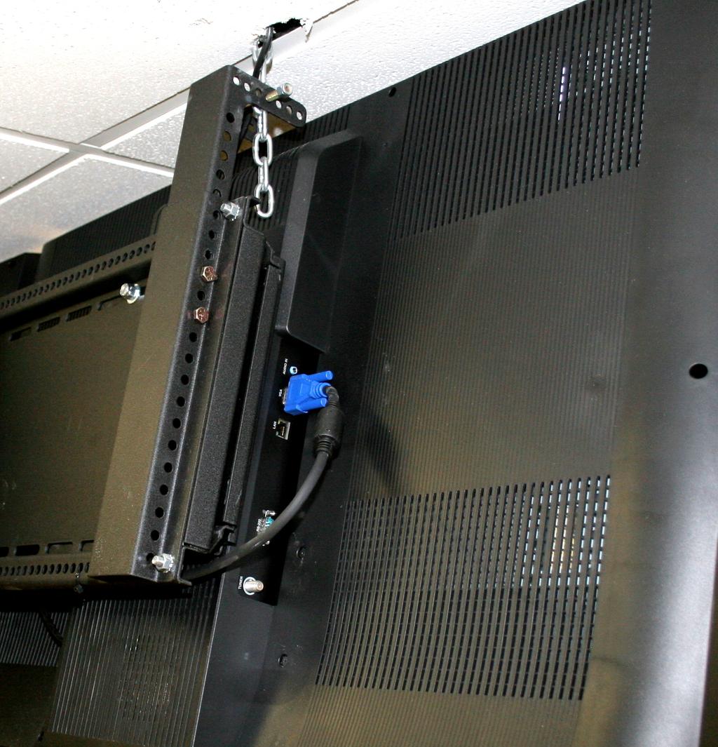
7 Step 5: Locate the Channel (Part D ) and install this to the back side of monitor bracket assembly. o There are many holes across the main plate (Part A ) that you can use for adhering to the existing chain and/or cables coming out of your ceiling. Step 6: Insert the hanger (Part E ) into the channel (Part D ). When you insert this hanger into the channel, this hanger is reversible, as the top portion of this hanger is where you will be installing the chains or aircraft cable. In most cases, you will want the metal hanger to point towards the front of the main plate (Part A ) or in other words, towards the monitor and bowlers. This is all dependent on how many monitors, size of monitor, and weight of the monitors. You want to locate this hanger as low as possible into the channel so that it cannot be seen from the bowler s point of view from the concourse. Lower it down as far as possible below the monitor bezel so that it s hidden. See the image below, as the hanger assembly cannot be seen by the bowlers.
8

9 o o DO NOT OVERTIGHTEN the hardware that secures the hanger into the channel, as this will make it very hard to remove the hanger from the channel. The cap screw and locknut should only be tightened until the locknut BARELY touches the channel. The cap screw that holds the chain or aircraft cable into the hanger can be placed into any of the holes provided, and by using different holes; you can achieve a different angles in which the monitor assembly will hang. A high ceiling may require a larger tilt so the monitor can be viewed easier by the bowlers. This adjustment can be achieved to your liking, and remember you can always reverse the hanger assembly in the channel to achieve a different angle (or tilt) of the monitor frame assembly.


10 Step 7: Install the LCD monitors onto the frame assembly, and we suggest you mount all monitors to the frame assembly on the ground first. The reason for this is; the monitors are at ground level and can be fine-tuned (straightened out), with all hardware finally tightened to secure the monitor from being lifted off the frame. You must tighten these bolts shown below when the monitor has been assembled onto the main frame assembly!


11 The monitor plate (Part C ) above is used with any LCD monitor that supports the VESA standard bolt patterns. If you have purchased Hantarex LCD monitors, the adapter plate shown below will need to be installed.


12 Step 8: When you place the lane computer onto the monitor frame (Part A ) assembly, the lane computer can be installed easily with the plates supplied by Steltronic. o If you need to mount a Vision Lane Computer onto the monitor frame, using (Part G ), install the plates as shown below. The plates have a slotted mounting hole for removal of the lane computer. o If you need to mount a Super Elex to the monitor frame, secure the lane computer as shown below
Installation and Assembly: 2 x 2 Video Wall Ceiling Mount for 40" - 55" flat Panel Displays
 Installation and Assembly: 2 x 2 Video Wall Ceiling Mount for 40" - 55" flat Panel Displays Model: DS-VWT955-2X2 EXTENSION COLUMN (SOLD SEPARATELY) COMPATIBILITY Display width must be a minimum of 36"
SF Studio Series Set-Up Instructions
 SF Studio Series Set-Up Instructions Teleprompter Parts Step #1 Remove the quick-release plate from your tripod head. Set the plate on a flat surface (table, desk, etc) with anti-skid pads on top & camera
2 x Dynamic Arms on 135 Post with C-Clamp
 Installation Guide AWMS-2-D13-C 2 x Dynamic Arms on 135 Post with C-Clamp COMPONENT CHECKLIST RANGE A AWM-LC Post Clamp B AWM-AD Dynamic Arm (x2) C AWM-P13 135 Post D AWM-FC C-Clamp CONTENTS C-Clamp Page
Setup Information Panosaurus May 3, 2011
 Setup Information Panosaurus 2.0 www.gregwired.com May 3, 2011 Please take the time to read all of the setup information to ensure success and ease of use of this tripod head. Much of the setup is a one
Extra Large Full Motion TV Mount for Televisions
 8008981 TV Size Range: 47 ~ 84 Maximum Weight Capacity: 60 kg/132 lbs Maximum Mounting Pattern: 800 mm x 600 mm (31.4 x 23.6 ) Distance to the Wall: 5.5-45 cm Extra Large Full Motion TV Mount for 47-84
Remote Control Motorized TV Ceiling Mount
 INSTALLATION MANUAL Remote Control Motorized Ceiling Mount CAUTION: DO NOT EXCEED RATED LISTED WEIGHT. SERIOUS INJURY OR PROPERTY DAMAGE MAY OCCUR! DEHA-400E 15 200x200 300x300 400x200 400x400 55" MAX
Assembly and mounting Instructions
 PMS-FL Assembly and mounting Instructions Note: Keep your original packaging until assembly is complete. Two persons are required to attach plasma/lcd displays to this mount. If you cannot understand these
The QSR kitchen video bracketing options can be assembled to fit your specific kitchen environment needs.
 QSR Kitchen Video Bracket Configurations and Instructions The QSR kitchen video bracketing options can be assembled to fit your specific kitchen environment needs. A variety of mounting solution configurations
How To Install: C4000 EMV Upgrade Kit
 How To Install: C4000 EMV Upgrade Kit IMPORTANT: Before proceeding with installation please verify you have the current card reader bezel in the kit. Correct bezel will have a small eject pin hole below
Create extra desk space and tidy up your cubicles
 Single-Monitor Mount - Cubicle Hanger StarTech ID: ARMCBCL With these cubicle monitor hangers, you can free up desk space by mounting monitors on the partitions between office cubicles. Each hanger can
Innovative Americans, LLC. HD Media Pack Installation Manual
 Innovative Americans, LLC HD Media Pack Installation Manual Please read this manual before you begin! Your installation will be EASIER and SAFER if you take a few moments to read this document!! Proudly
7403 K321. Display Wall Mount. Kit Instructions. Issue A
 7403 K321 Display Wall Mount Kit Instructions Issue A ii Revision Record Issue Date Remarks A Nov 2008 First issue 1 Introduction This kit is used in to secure a 7403 Display Head on a vertical surface.
Digital Menu Board Wall Mount Installation Instructions
 Digital Menu Board Wall Mount Installation MDSWMB2T4249 MDSWMB3T4249 www.microndisplaysolutions.com Table of Contents Important Safety... 3 Models and Specifications... 4 Package Contents... 5 Step 1 Two(2)
Peel/Rewind Upgrade Kit
 Peel/Rewind Upgrade Kit Installation Instructions This kit includes the parts and documentation necessary to install the Peel/Rewind upgrade kit on the following printers: ZM400 ZM600 Read these instructions
Treadmill Integrated LCD Screen Option. Cardio Theater Integrated Bracket Assembly Instructions
 Treadmill Integrated LCD Screen Option Cardio Theater Integrated Bracket Assembly Instructions Table of Contents 1 2 3 4 5 6 Before You Begin... 4 Obtaining Service... 4 Unpacking the Equipment... 4 Important
Apple imac Stand for Winston Workstation Installation Instructions
 8502 Apple imac Stand for Winston Workstation Installation Instructions PAGE 1 OF 4 2015 Innovative Office Products, LLC P512127 REV A 8502 Apple imac Stand for Winston Workstation Parts List A Shelf Bracket
Picture Rail. Designed for any space where artworks go on walls, from galleries and public buildings to offices, shops, and residences.
 The Picture Rail lineup for buildings of many types: commercial facilities, public facilities, museums, galleries, and residences. Versatile solutions for displaying pictures beautifully on walls without
Cycles Integrated LCD Screen Option. Cardio Theater Integrated Bracket Assembly Instructions
 Recumbent Upright Cycles Integrated LCD Screen Option Cardio Theater Integrated Bracket Assembly Instructions Table of Contents 1 2 3 4 5 6 7 Before You Begin... 4 Obtaining Service... 4 Unpacking the
ASSEMBLY INSTRUCTIONS, ELO SELF SERVICE STAND
 ASSEMBLY INSTRUCTIONS, ELO SELF SERVICE STAND E062324 ELO-STAND-SELF-SERVICE-DESKTOP E062510 ELO-STAND-SELF-SERVICE-FLOOR EXT E062704 KIT-EMV-CRADLE-VF-MX915-ING-ISC250 E062899 KIT-EMV-INGENICO IPP350
TV Brackets by equip The perfect solution to securely mount your TV
 TV Brackets by equip The perfect solution to securely mount your TV No matter what s the size, if you want your TV in a fix position or want it to tilt, we have the solution you re been looking for. intro
 Photography tripod Why do I Need a Tripod? http://www.bhphotovideo.com/explora/video/buying-guides/what-look-when-you-are-looking-videotripod Tripod Tricks? http://vimeo.com/videoschool/lesson/110/tripod-tricks
Flat Panel Static Wall Mount MSP-SS (GSM-210)
") INSTALLATION INSTRUCTIONS Flat Panel Static Wall Mount (GSM-2) The static wall mount fits most 23 to 30 displays. The mount was designed to adapt to the VESA 75mm/0mm, 0mm/0mm, and 200mm/0mm compliant
INSTALLATION INSTRUCTIONS Flat Panel Static Wall Mount (GSM-2) The static wall mount fits most 23 to 30 displays. The mount was designed to adapt to the VESA 75mm/0mm, 0mm/0mm, and 200mm/0mm compliant
Written By: Teren Wallace
 In this guide, we will be showing you how to remove and replace the Touch Pad. Written By: Teren Wallace ifixit CC BY-NC-SA www.ifixit.com Page 1 of 26 INTRODUCTION In this guide, we will be showing you
Sony NEX-7 Screen Replacement
 Sony NEX-7 Screen Replacement If your camera's screen is broken or non functioning, this guide will show you how you can replace the screen. Written By: Jay Miley ifixit CC BY-NC-SA www.ifixit.com Page
CHIEF Stand. K3F220/K3G220 (2x2) K3G320 (3x2) EX241UN / -H Multi-Screen Installation Manual
 K3G320 (3x2) EX241UN / -H Multi-Screen Installation Manual") CHIEF Stand K3F220/K3G220 (2x2) K3G320 (3x2) EX241UN / -H Multi-Screen Installation Manual Contents General Information and Cautions. 3 Chapter 1 Removing the Bezel 4 Purpose. 4 How to Remove the Bezel......................5
CHIEF Stand K3F220/K3G220 (2x2) K3G320 (3x2) EX241UN / -H Multi-Screen Installation Manual Contents General Information and Cautions. 3 Chapter 1 Removing the Bezel 4 Purpose. 4 How to Remove the Bezel......................5
ASSEMBLY AND ADJUSTMENT
 EDGE-WALL MONITOR ARM EDGE-WALL Rev A 2/17 Model EDGE-WALL-SLV ASSEMBLY AND ADJUSTMENT EDGE-WALL MONITOR ARM PLEASE REVIEW these instructions before beginning the installation. Check that all parts and
CLIMB2 DUAL MONITOR SIT/STAND WORKSTATION
 CLIMB2 DUAL MONITOR SIT/STAND WORKSTATION CLIMB2 Rev A 3/17 Model CLIMB2-SLV ASSEMBLY AND ADJUSTMENT CLIMB2 PARTS AND TOOLS PLEASE REVIEW these instructions before beginning the assembly and adjustment
WINSTON WORKSTATION INSTALLATION INSTRUCTIONS. STEP 1 COLUMN...Page 2
 WINSTON WORKSTATION INSTALLATION INSTRUCTIONS STEP COLUMN...Page 2 STEP 2 MOUNTS Free Standing Base...Page 3 Clamp Mount...Page 4 Thru Mount...Page 5 6 STEP 3 WORK SURFACE...Page 6 8 STEP 4 CENTER BEAM...Page
Universal Desktop and Monitor Stand
 Universal Desktop and Monitor Stand Installation Instructions Kit P/N: 114-6013 Kit Contents Kit Contents: (1) Stand Assembly (1) VESA Monitor Bracket (1) Bottom Bracket (1) Top Bracket (1) Clamp Bracket
Assembly Instructions for #5630 Medication PalWOW
 Assembly Instructions for #5630 Medication PalWOW Before assembling, please familiarize yourself with all the parts and check to make sure you have all the parts as listed below. A B A & B - The box in
TV & Office Solutions by equip solutions with a high value of benefit
 TV & Office Solutions by equip solutions with a high value of benefit The brand equip stands for a product development driven by quality management and continuous adjustments to the requirements of the
To connect the AC adapter:
 Replacing the AC Adapter Replacing the AC Adapter 3 Plug the power cord into a wall outlet. The power indicator turns on. To connect the AC adapter: Connect the power cord to the AC adapter. Power indicator
User s Guide. Includes Mounting, Installation, and Product Registration nd Avenue NE Arlington, WA USA (+1)
") User s Guide Includes Mounting, Installation, and Product Registration 500 19009 62nd Avenue NE Arlington, WA USA (+1) 360-435-6030 European Sales Office Barcelona, España (+34) 600-843-845 www.outbackpower.com
User s Guide Includes Mounting, Installation, and Product Registration 500 19009 62nd Avenue NE Arlington, WA USA (+1) 360-435-6030 European Sales Office Barcelona, España (+34) 600-843-845 www.outbackpower.com
EasyIO FG-20 Installation Guide v1.1. FG-20 Installation Guide
 EasyIO FG-20 Installation Guide v1.1 FG-20 Installation Guide 1 EasyIO FG-20 Installation Guide v1.1 Document Change Log 26 th Feb 2013 Document created. 27 th Dec 2013 Micro SD card installation 2 EasyIO
CIB 3047 (14B) 10-Button Voice Terminal Fixed Desk Stand and Wall Mount (32007)
 10-Button Voice Terminal Fixed Desk Stand and Wall Mount (32007)") CIB 3047 (14B) 10-Button Voice Terminal Fixed Desk Stand and Wall Mount (32007) CIB 3047 Comcode 845-659-325 Issue 1 CIB 3047 (14B) 10-Button Voice Terminal Fixed Desk Stand and Wall Mount (32007) This
CIB 3047 (14B) 10-Button Voice Terminal Fixed Desk Stand and Wall Mount (32007) CIB 3047 Comcode 845-659-325 Issue 1 CIB 3047 (14B) 10-Button Voice Terminal Fixed Desk Stand and Wall Mount (32007) This
EVO-TM2A EVO-TM2B Touch Screen Monitor
 User Manual Revision v1.3 Dec. 2010 EVO-TM2A EVO-TM2B Touch Screen Monitor Copyright 2010 August All Rights Reserved Manual Version 1.3 Part Number: The information contained in this document is subject
SKYLINE TRIPOD KIT. Micro-Fluid Head. Adjustable Quick-Release Plate. Center Column Height Adjustment Knob. Leg Angle Release Tabs.
 Your Skyline TM tripod features rugged anodized legs and a smooth, precise, micro-fluid head for rock-solid performance in the most demanding situations. Adjustable Quick-Release Leg Angle Release Tabs
V.I.A. - Monitor Shroud
 V.I.A. - Monitor Shroud NOTE: Installing slatwall above a monitor shroud requires modification of the upper horizontal rail. See V.I.A. Slatwall assembly direction 939502328 for installation process. V.I.A.
HQuad500 Frame Assembly Guide
 HQuad500 Frame Assembly Guide V1.0 June 2015 1 What s Included Kit Content Hardware Bag Content 2 HQuad500 Assembly 2.1 Arm & Motor Mount Sub Assembly 2.2 Landing Gear Step 1 2.3 Center Plates Sub Assembly
Rear Consumer LCD Hinge Assembly Large Displays
 7403-K454 Rear Consumer LCD Hinge Assembly Large Displays Kit Instructions Issue D Revision Record Issue Date Remarks A Nov 2008 First issue B June 2009 Removed Power Cable from the kit contents C May
AP-120 Series AP Mounting Kit
 AP-120 Series AP Mounting Kit Installation Guide The AP-120 series mounting kit provides additional mounting options for the AP-120 series wireless access points. The mounting kit includes the following
System Storage EXP3000 Rack Installation Instructions
 System Storage EXP3000 Rack Installation Instructions Review the documentation that comes with your rack cabinet for safety and cabling information. When you install the IBM System Storage EXP3000 in a
Articulated Freestanding Dual Monitor Desk Stand - 13" to 27" Installation Instructions
 Articulated Freestanding Dual Monitor Desk Stand - 13" to 27" Installation Instructions 04-1019A 1 Unpacking Carefully remove the contents and lay them out on cardboard or other protective surface Check
PFPDARM3 Product Illustration
 PFPDARM3 Product Illustration page 1 of 15 PFPDARM3 Components & Fasteners 1x 1x 4x 4x 8x 4x 1 each TOOLS REQUIRED Phillips Screwdriver 1/2" Wrench 1/2" Socket Wrench 3/32" (2.38mm) 3/16" (4.76mm) 1/8"
Advanced Camcorder Support System. Instruction Manual
 Advanced Camcorder Support System Instruction Manual PAG ORBITOR Advanced Camcorder Support System Instruction Manual CONTENTS SECTION PAGE 1 SAFETY 2 2 ASSEMBLY & OPERATION 3 3 PARTS AND ASSEMBLIES 9
Eaton LCD Lift Flat Panel Display System. Installation Guide
 Eaton LCD Lift Flat Panel Display System Eaton LCD Lift Flat Panel Display System Installation Guide Copyright 2011 Eaton Corporation, Worcester, MA, USA. All rights reserved. Information in this document
AS7.P CF20 NPT DOCK AS7.P CF20 DPT DOCK AS7.P CF20 NPT DOCK WITH SCREEN LOCK AS7.P CF20 DPT DOCK WITH SCREEN LOCK AS7
 AS7.P020.100 CF20 NPT DOCK AS7.P020.102 CF20 DPT DOCK AS7.P020.200 CF20 NPT DOCK WITH SCREEN LOCK AS7.P020.202 CF20 DPT DOCK WITH SCREEN LOCK AS7.P020.001 CF20 SCREEN LOCK ARM PANASONIC TOUGHBOOK CF20
Articulated Freestanding Triple Monitor Desk Stand - 13" to 27" Installation Instructions
 Articulated Freestanding Triple Monitor Desk Stand - 13" to 27" Installation Instructions 04-1020A 1 Unpacking Carefully remove the contents and lay them out on cardboard or other protective surface Check
Rack Installation Instructions
 Rack Installation Instructions For System Storage EXP2512 and EXP2524 Express Storage Enclosures Use the instructions in this document to install an IBM System Storage EXP2512 Express Storage Enclosure
HARMONi G3. Quick Start Guide for HARMONi G3. imac Processor/FireWire Upgrade
 HARMONi G3 imac Processor/FireWire Upgrade imac and Operating System Compatibility The HARMONi G3 imac processor/firewire upgrade is compatible only with imac 233, 266, and 333 MHz models (Revisions A-D);
How To Install: G2500 EMV Upgrade Kit
 How To Install: G2500 EMV Upgrade Kit Tools Needed: Phillips Screw Driver Wire Cutter - Begin by verifying the contents of the kit Kit includes: - EMV Card reader (with ground and data cable) - Card reader
Keypad Lock. Operation and Service Manual. Order parts online
 Keypad Lock Order parts online www.follettice.com Operation and Service Manual 801 Church Lane Easton, PA 18040, USA Toll free (800) 523-9361 (610) 252-7301 Fax (610) 250-0696 www.follettice.com 00163345R00
Floor Standing Pedestal
 2336 K052 Floor Standing Pedestal Kit Instructions Issue C Revision Record Issue Date Remarks A Feb 20021 First issue B June 2007 Added pedestal floor bolting procedure C Mar 2011 Added Universal Mounting
Sit-Stand Monitor Arm
 Sit-Stand Monitor Arm Product ID: ARMSTSCP1 This sit-stand monitor arm transforms your desk or tabletop into an ergonomic workstation. The monitor arm features a keyboard tray and easy height adjustment
HD Flex Zero RU Cassette Holder and Bracket
 HD Flex Zero RU Cassette Holder and Bracket Part Numbers: FLEX-0RUBR**, FLEX0RUCH** Panduit Corp. 2016 INSTALLATION INSTRUCTIONS The Zero RU Cassette Holder and Bracket are designed to mount on the side
Product Overview. Features
 APCF1 Model Tripod Product Overview The Ravelli APCF1 is a Professional Quality Carbon Fiber Tripod providing a solid base for high-end photographic equipment. This model is a mix of carbon fiber and magnesium
Gateway Profile 4 service guide
 Gateway Profile 4 service guide Customizing Troubleshooting Contents Replacing Components in Your Gateway Profile 4.................. 1 About this guide.....................................................
NBS-2X NIMBUS STABILIZER QUICK-START GUIDE
 NBS-2X NIMBUS STABILIZER QUICK-START GUIDE PREC AUTIONS Please read and follow these instructions and keep this manual in a safe place. Keep this product away from children. Make sure everything is secure
Rack Installation Instructions
 Rack Installation Instructions Review the documentation that comes with your rack cabinet for safety and cabling information. Before installing your server in a rack cabinet, review the following guidelines:
EasyIO FG-32 Installation Guide v1.2. FG-32 Installation Guide
 FG-32 Installation Guide 1 Document Change Log 26 th March 2013 Document created. 27 th Dec 2013 Micro SD card installation 17 th August 2015 Micro SD card installation for EasyIO FG+. 2 Disclaimer EasyIO
Flip Plate Operation Manual ver: 1.1
 Flip Plate Operation Manual ver: 1.1 1. Standard Flip Plate operation. page 2 2. Operation of the Flip Plate when no Card Box is in use. page 4 3. How to remove the Flip Plate from the machine. page 4
How to replace the memory card slot board and DVD drive DIGITAL PHOTO PRINTER UP-CR20L
 How to replace the memory card slot board and DVD drive DIGITAL PHOTO PRINTER 1-1. Parts Location Card PC board assembly 1-1 1-2. Card PC Board Assembly m. Take care not to hurt your hands or other by
P160 User s Manual Manuel de l utilisateur Anwenderhandbuch Manuale per l operatore Manual del usuario
 P10 User s Manual Manuel de l utilisateur Anwenderhandbuch Manuale per l operatore Manual del usuario At Antec, we continually refine and improve our products to ensure the highest quality. So it's possible
IBM. Rack Installation Instructions
 IBM Rack Installation Instructions Review the documentation that comes with your rack cabinet for safety and cabling information. When installing your server in a rack cabinet, consider the following:
MD-BSL15W / SPRING-LOADED TWIN-ARM. For ( cm) LCD desktop computer. User Manual
 LCD desktop computer. User Manual") MD-BSL15W / SPRING-LOADED TWIN-ARM MONITOR mount For 15 27 (38.1 68.6 cm) LCD desktop computer User Manual Thank you for choosing Gabor. The Gabor MD-BSL15W mounts two 15 27 (38.1 68.6 cm) LCD computer
MD-BSL15W / SPRING-LOADED TWIN-ARM MONITOR mount For 15 27 (38.1 68.6 cm) LCD desktop computer User Manual Thank you for choosing Gabor. The Gabor MD-BSL15W mounts two 15 27 (38.1 68.6 cm) LCD computer
A note about our online installation instructions:
 A note about our online installation instructions: Most Modern Fan Co. products have been in our assortment for several years or longer. As we continually work to improve product performance and user experience,
Addendum to the Actalyst Interactive Digital Signage Installation and User s Guide
 Addendum to the Actalyst Interactive Digital Signage Installation and User s Guide This addendum contains information about the Actalyst Interactive Overlay that has changed since the release of the Actalyst
DIGITAL Server Rackmount Installation Guide
 DIGITAL Server Rackmount Installation Guide Part Number: ER-PCSRA-IA. E01 Digital Equipment Corporation December 1997 The information in this document is subject to change without notice and should not
USBCNC USB Disk Key reader for CNC Controls Machine Mount instructions
 USBCNC USB Disk Key reader for CNC Controls Machine Mount instructions 2008-2015 Calmotion LLC, All rights reserved Calmotion LLC 21720 Marilla St. Chatsworth, CA 91311 www.calmotion.com Introduction This
AV mounting systems Q4-2009
 AV mounting systems Q4-2009 Table of content 1 Table of content 1 SmartMetals projector mounts 2 Universal tube sets 3 Separate tube sets 4 Mirror kit & anti-theft set 5 Universal projector housings 6
Disassembly Manual Version 1.1
 EasyNote K5 Disassembly Manual Version 1.1 Required Tools Disassembly Instructions DIP Switch Setting Reassembly Instructions Required Tools ll EasyNote K5 maintenance procedures can be performed using
Quick Installation Guide
 Full Motion Dual Monitor Arm, Pole Mount Quick Installation Guide Please Review the entire Quick Installation Guide prior to installation. If you have any questions regarding the compatibility of this
AVT Model Tripod.
 AVT Model Tripod www.ravelliphoto.com Product Overview: The Ravelli AVT professional tripod is a high performance, fluid drag tripod that provides smooth continuous drag control and operates on both pan
Formulate Designer Series 20 Backwall - Kit 11
 Formulate Designer Series 20 Backwall - Kit 11 FMLT-DS-20-11 Formulate Designer Series 20ft displays have unique stylistic features and shapes, are portable and easy to assemble. The aluminum tube frame
NAV-1 Lens Support. NAV-2 Lens Support BEFORE YOU BEGIN
 INSTALLATION Lens Support INSTRUCTIONS The Lens Support is compatible with any RPA projector mount. The readily adapts to the following ScreenStar Conversion Lens from Navitar: SSW08 and SST120. LENS SUPPORT
SAVE THESE INSTRUCTIONS
 and Height Mounts Assembly, Installation and Operating Instructions Model Nos. QL, QLA, ARM250, QLM6 and QLAM6 NOTE: Check all parts for shipping damage. In case of shipping damage, DO NOT use. Contact
Written By: Sam Lionheart
 iphone 5c Front Panel Replacement Replace the Front Panel on your iphone 5c. Written By: Sam Lionheart ifixit CC BY-NC-SA www.ifixit.com Page 1 of 24 INTRODUCTION For an easier repair, use our fix kit
C764i Integrated LCD Screen Option. Cardio Theater Integrated Bracket Assembly Instructions
 C764i Integrated LCD Screen Option Cardio Theater Integrated Bracket Assembly Instructions Table of Contents 1 2 3 4 5 6 7 Before You Begin... 3 Obtaining Service... 3 Unpacking the Equipment... 3 Important
The basic product comes with the IRS5 control board, 3 internal cables, 1 external cable with a 5 volt adapter and a mounting bracket with hardware.
 Please read these instructions and watch the Installation Video before you proceed with the installation of the PC-IRS5-01. Installation Video: http://youtu.be/os98e32vhb4 The PC-IRS5-01 Infrared Receiver
Replacing the Encoder Strip
 6-1-11. Replacing the Encoder Strip The following describes the procedure for replacing the Encoder Strip. Refer to the diagram below for identifying the parts and their positions. (The numbers shown in
Further Information can be found at
 Below is a step by step guide to assembling the Hurricane-Rig. Remember that this is a precision optical instrument. Excessive force can bend critical parts. If treated well it should give many years of
A-MOD DESKTOP OWNER S MANUAL
 A-MOD DESKTOP OWNER S MANUAL GOJOTTO.COM 877-55-6886 IMPORTANT NOTICE: Please take a few minutes to read through this Owner s Manual before using the product to ensure that your A-MOD Desktop will be operated
Quick start guide for i5 520 ( or )
") Quick start guide for i5 520 (9405-520 or 9406-520) 1 Before you begin This Quick start guide contains an abbreviated set of setup instructions designed to help you quickly unpack and set up a standard
Quick start guide for i5 520 (9405-520 or 9406-520) 1 Before you begin This Quick start guide contains an abbreviated set of setup instructions designed to help you quickly unpack and set up a standard
EVOLVE1-M MONITOR ARM
 EVOLVE1-M MONITOR ARM EVOLVE1-M Rev A 2/17 Model EVOLVE1-M-SLV Model EVOLVE1-M-BLK Model EVOLVE1-M-WHT ASSEMBLY AND ADJUSTMENT EVOLVE1-M MONITOR ARM PARTS AND TOOLS PLEASE REVIEW these instructions before
Yamaha DX7 LCD Installation Guide
 Table of Contents Required Tools/ Getting Started... p. 2 Installation... p.3-11 Opening the DX7... p. 3 Locating and Removing the LCD Bracket... p. 4 Removing the LCD Bezel Cover... p. 5 Removing the
Replacement Instructions
 imac G5 Inverter, 20-inch Replacement Instructions Follow the instructions in this document carefully. Failure to follow these instructions could damage your equipment and void its warranty. Note: Online
Biesemeyer Fence Kit Installation Instructions:
 Biesemeyer Fence Kit Installation Instructions: Please note this installation kit is designed solely for installation on a Biesemeyer Commercial Fence. Accurate Technology manufactures kits for other saw
2017 HI-POD INC. (PAGE 1) SETUP MANUAL. Hi-Pod Inc Laurel Canyon Blvd. North Hollywood, CA
 SETUP MANUAL. Hi-Pod Inc Laurel Canyon Blvd. North Hollywood, CA") 2017 HI-POD INC. (PAGE 1) SETUP MANUAL 2017 HI-POD INC. (PAGE 2) Manual Index: 3 - Welcome 4 - Checklist 5 - Three Important Things 6 - Pole Bag and Camera Bag 7 - Getting Started: Take The Main Stucture
2017 HI-POD INC. (PAGE 1) SETUP MANUAL 2017 HI-POD INC. (PAGE 2) Manual Index: 3 - Welcome 4 - Checklist 5 - Three Important Things 6 - Pole Bag and Camera Bag 7 - Getting Started: Take The Main Stucture
DSLR Filmmaking Kit 6-CF
 DSLR Filmmaking Kit 6-CF INSTRUCTION MANUAL All rights reserved. No part of this document may be reproduced, stored in a retrieval system, or transmitted by any form or by any means, electronic, mechanical,
Dell Wyse Client VESA Mounting Bracket for Dell P Series Monitor Installation Instructions
 Dell Wyse Client VESA Mounting Bracket for Dell P Series Monitor Installation Instructions This VESA mounting bracket (P bracket) is used for mounting a Wyse client to the Dell P Series Monitor or the
LCD Series & Tablet Series Set-Up Instructions
 LCD Series & Tablet Series Set-Up Instructions Parts List: Mount Arm (1) T-Nut (1) Large Camera Knob (1) Small Camera Knob (1) Mirror Knob (2) Monitor/Mirror Assembly (1) Teleprompter Parts Step #1A Remove
iphone 6S Full Display Assembly Replacement
 iphone 6S Full Display Assembly Replacement INTRODUCTION Use this guide along with the Werx Repair Mat to replace the cracked or broken screen on your iphone 6S. Follow Werx Repair Mat Steps 1,2,5 to disassemble.
USBCNC-SW USB Disk Key reader for CNC Controls Machine Mount instructions for Universal Switcher Version
 USBCNC-SW USB Disk Key reader for CNC Controls Machine Mount instructions for Universal Switcher Version 2015 Calmotion LLC, All rights reserved Calmotion LLC 21720 Marilla Street Chatsworth, CA 91311
Mini FPV Tricopter / Vtail / Quadcopter
 Mini FPV Tricopter / Vtail / Quadcopter Frame Assembly Manual / Tips and Tricks Armattan Minis Website: http://www.armattanminis.ca/ Main Armattan Website (doesn t have minis): http://www.armattanquads.com/
LED Lighting Kit For Elara NanoEdge Fixed Frame. Installation Guide. Attention: Read this guide before assembling your screen.
 LED Lighting Kit For Elara NanoEdge Fixed Frame Installation Guide Attention: Read this guide before assembling your screen. INTRODUCTION GETTING STARTED WARNING - Sharp Edges This product may contain
INSTALLATION INSTRUCTIONS
 INSTALLATION INSTRUCTIONS 19 20 21 01 07 22 23 13 10 12 08 17 18 11 02 14 15 04 03 16 WELCOME PARTS LIST Thank you for purchasing this HealthPoint Technology Cabinet from Humanscale! Before you begin installing
3D SYSTEMS University CubeX 3D Printer
 3D SYSTEMS University CubeX 3D Printer Lesson Leveling the Print Pad and Print Tips, Setting the Z-Gap Revision date: 10/22/13 1 1 2016 年 6 月 14 日 Objectives After completing this lesson you will: Be able
ipad Mini Wi-Fi Front Facing Camera Replacement
 ipad Mini Wi-Fi Front Facing Camera Replacement Replace the Front Facing Camera in your ipad Mini Wi-Fi. Written By: Andrew Optimus Goldberg ifixit CC BY-NC-SA www.ifixit.com Page 1 of 42 INTRODUCTION
HAW-SIBU. Rack Installation Guide. Version 1.0.1
 HAW-SIBU Rack Installation Guide Version 1.0.1 Mounting HAW-SIBU in a Rack The instructions here apply to the Sony HAW-SIBU. Cautions * Do not lift or move the HAW-SIBU unit by the handles on the ear brackets
Warning Before Installation
 Warning Before Installation English Power off the Network Camera as soon as smoke or unusual odors are detected. Refer to your user's manual for the operating temperature. Contact your distributor in the