Computer Assembly (Installing Mother Board & CPU)
|
|
|
- Elfrieda Harris
- 5 years ago
- Views:
Transcription
1 Computer Assembly (Installing Mother Board & CPU) HARDWARE TEAM Biju Thiruvananthapuram Sree Kumar Kottarakkara Shamsudeen Attingal Pradeep Mattara Wandoor
2 Pre-Installation Precaution Mother board contains very electric sensitive components and will be very easily damaged if handled improperly. Unplug the power Cord from the wall socket before touching any component. Failure to do so may cause severe damage to the motherboard, peripherals, and / or components.
3 Pre-Installation Precaution (2) To avoid damaging the motherboard components due to static electricity, NEVER place your motherboard directly on the carpet or the like. Also remember to use a ground wrist strap or touch a safety grounded object before you handle components.
4 Pre-Installation Precaution (3) Hold the componet by the edge and do not touch the ICs. Whenever you uninstall any components, pleace it on a grounded antistatics pad or in the bag that comes with the component. When placing screw into the screw holes to secure the motherboard to the chassis, please DO NOT over- tighten the screws! Doing so may permanently damage the motherboard.
5 Pre-Installation Precaution (4) Never put your motherboard on any metal Surface. Be careful when you connect the power plug with your motherboard.

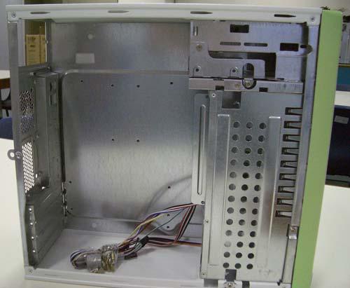
6 Opening the Case


7 Replace the ATX Connector Plate Remove the ATX Connector Plate from the Case Befor e After


8 Replace the ATX Connector Plate Find the Connect Plate that come with the Motherboard and place it on the case Befor e Afte r

9 Determine Mother Board Mounting Location


10 Install the Motherboard Standoffs Install the standoffs in the appropriate location. The standoffs may come a variety of styles. The most common is the brass hex standoff that requires a hex driver to install. Others include a clip style that snaps into the tray.

11 Fasten the Motherboard Lay the motherboard over the tray and align the board so all the standoffs are visible through the mounting holes. Starting with the center most mounting point, insert the screws to fix the motherboard to the tray. After the center, work in a star pattern to affix the corners of the board.
12 Knowing Your MotherBoard Motherboard connects all the computer component (CPU, Hard Disk, RAM, Video Card, Other USB Device etc) together. Introduce different part of Motherboard. You should familiar with your motherboard before install any component on it.

13 Knowing Your MotherBoard - This is an Intel socket 775 Motherboard. Different CPU use different Motherboard, make sure your CPU is compatible with your motherboard if you buy them separately. CPU Socket
 DIMM Slots. It support Dual Channel memory Technology.")
14 Knowing Your MotherBoard - This is a 240 pins DDRII (Double Data Rate II) DIMM Slots. It support Dual Channel memory Technology. Memory slot

15 Knowing Your MotherBoard - Floppy Disk Connector It is a 33 / 34 pins connector which used to connect the motherboard to a 3.5 floppy disk.
16 Knowing Your MotherBoard - Primary ATA Connector It is a 39 / 40 pins IDE Connector which used to connect to IDE hard disk or CD ROM or DVD ROM.
17 Knowing Your MotherBoard - SATA Connector These SATAII (Serial ATAII) connectors used to connect SATA hard disk for internal storage device. This

18 Knowing Your MotherBoard - USB Headers Besides the default USB ports on the I/O panel, some motherboard do provides additional USB headers on the motherboard to connect to the case USB Connector. Each USB 2.0 header can support up to two USB 2.0 Ports.

19 Knowing Your MotherBoard - Infrared Module Header This header support an optional wireless transmitting and receiving module.

20 Knowing Your MotherBoard - Internal Audio Connector This connector allow transmitting stero audio from other sound source such as CD ROM, DVD ROM or TV capture
21 Knowing Your MotherBoard - System Panel Connector This header accommodates several system front panel function. Power button, reset button, hard disk indicator and power indicator
22 Knowing Your MotherBoard - Chassis Speaker Header If your case has a speaker, you should connect your speaker to this header.
23 Knowing Your Motherboard - CPU Fan Connector Connect a Case fan power cord this this connecter. Once you have a correct fan connected, your BIOS can detect the existing of the fan and its rotation speed. Fan speed will be automatically adjusted depends on the motherboard and other

24 Knowing Your Motherboard - Chassis Fan Connector Similar with the CPU Fan Connector, it s used to connect the Case Fan in order to increase the ventilation.

25 Knowing Your Motherboard - ATX Power Connector Connect the ATX Power supply connector to provide power for all the component.

26 Knowing Your Motherboard - ATX 12V Connector Some motherboard do requires to connect a power supply with ATX 12V plug to this connector so that it can provide sufficient power.

27 Knowing Your Motherboard - Allow you to add any addition device which communicate with a PCI slot. Example of PCI slot device include TV capture card, Network Card etc PCI Slot

28 Knowing Your Motherboard - Battery This battery provide power for the BIOS to store information and maintain the clock to run when the system is power-down. Running out of this battery will cause the system setting
29 Get ready to Install Component! You are now familiar with your mother board. It s Now ready to install the motherboard into the case.

30 Installation of CPU Don t touch the CPU! DO NOT touch the CPU. It s very easy damaged. Hold the edge of the CPU and place it on the CPU socket properly.

31 Installation of CPU (Socket 775) Disengaging the lever by depressing down and out on the hook to clear retention tab.

32 Installation of CPU (Socket Rotate the load plate to fully open position at approximate 100 degree. 775)

33 Installation of CPU (Socket Rotate the load lever to fully open position at approximately 135 degrees. 775)

34 Installation of CPU (Socket Hold the CPU by the edges where marked with black lines. Locate the two orientation key notches. 775)
 up. Locate Pin 1 and the two orientation key notches.")
35 Installation of CPU (Socket Orient the CPU with IHS (Integrated Heat Sink) up. Locate Pin 1 and the two orientation key notches. 775)


36 Installation of CPU (Socket 775) Carefully place the CPU into the socket by using a purely Vertical motion. Remove the PnP Cap. This Cap protect the CPU Socket

37 Installation of CPU (Socket Verify that the CPU is within the socket properly mated to the orient keys. 775)
38 Installation of CPU (Socket 775) Close the Socket Rotate the load plate onto the IHS While pressing down lightly on load plate, engage the load lever. Secure load lever with load plate tab under retention tab of load lever.


39 Installing the CPU Heat Sink Most CPU Heat Sink come with a CPU Fan. You have to place the Heat Sink on top of the CPU.

40 Secure the CPU fan Secure the CPU Fan on the motherboard by pressing the knob until you heard a click.


41 Connect the CPU Fan with the Connect the CPU Fan to the Motherboard CPU Fan Socket Mother Board
42 Installation of Memory Module Caution! - The first step whenever you work on a computer system is to fully power down the computer system. Shut down the computer. Once the operating system has safely shut down, flip the switch on the back of the power supply to the off position and remove the AC Power Cord.
43 Locating the Memory Module Slots Examine the motherboard to locate the memory module slots. If the module slots are located under a power supply or drive, it may be necessary to remove additional parts to access the slots to install the memory modules.

44 Locating the Memory Module Slots Depends on different model, Some Motherboard have four memory slots while some of them only have two. In order to properly insert the memory
45 Insert the Memory Module To insert the memory module into the slot, align the memory module above the slot and make sure that the notch in the memory module is in the correct position. When the module is properly align, gently press down on both sides of the memory module downward into the slot. It should click into

46 Insert the Memory Module

47 Fasten the Module Clamps (if required) Make sure your memory module clamps have been fasten the modules. Normally when you place your memory module correctly, the clamps will be automatically fasten the memory.
48 Installation of Power Supply Different Computer case have different computer power supply. You should buy a suitable computer supply otherwise it will not fit your case. Power supply provide stable voltage to the computer. If there is any problem with your power supply, your computer will become very unstable

49 The Power Supply Mount Some computer case has the power supply mount, use your screw driver to loose the screw and get the power supply mount.

50 The Power Supply Mount Fasten the mount together with the power supply.

51 Fasten the Power Supply You should fasten the Power supply before putting it back to the computer case.

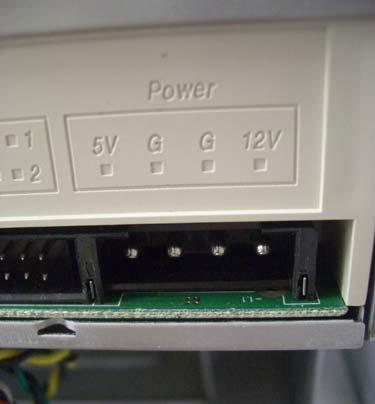
52 Check Your Power Supply Voltage Check Your power supply voltage selector to see whether it has select to 220V or 230V before connecting

53 Place the Power Supply back to After secure the Power Supply with the mount, you can place the Power Supply back to the Case and secure it with a screw driver. the case
54 Knowing Your Power Supply Power Supply comes out with several plugs different plug serves different function, basically you will easily identify different type of plug by their outlook.

55 Power Plugs For Motherboard These two plugs are used to provide power to the Motherboard.

56 Power Plug For SATA Hard Each Computer should have a hard drive, this power plug is designed for SATA Hard Drive. Drive


57 Power Plug For ATA Hard Drive / CDROM This plug is designed for providing power for ATA / IDE Hard Drive, CDROM / DVD ROM. Some Motherboard or video card require this kind of power plug.


58 Power Plug For Floppy Drive Although 3.5 floppy is not popular nowadays, The Power Supply for floppy disk still provided by power supply.
59 Connect the ATX Power Connector Different Motherboard requires different Power Socket. Some Motherboard requires 20 Pins, some requires 24


60 Connect the ATX Power Connector Locate the Power Socket in the Motherboard. Some motherboard have more than one power Connectors, you should read the user manual carefully, otherwise, your computer cannot be switch on.


61 Connect the ATX Power Connector Plug the power plug into the socket to provide power for the mother board.
62 Installation of Hard Disk In this tutorial, we are going to install an SATA Hard Disk. Some Motherboard does not support SATA Hard Disk will use IDE / ATA Hard Disk instead.

63 Locate the SATA Cable Connector Locate the STAT Hard Disk Connector on the Motherboard. For those Motherboard does not have SATA Connector, you may need to purchase an

64 Attach SATA Cable to the Motherboard There are two ends for a SATA cable. One end of the cable connected to the Motherboard while the


65 Attach SATA Cable to the Hard Disk

66 Installation of IDE CDROM / DVD ROM The follow step describe a proper method to install an ATA based optical drive into a desktop computer system. These instructions are valid for any form of optical based drive such as CD-ROM, CD-RW DVD-Rom or

67 Place the CD / DVD Drive into the Case

68 Identify the IDE / ATA Signal An IDE / ATA Signal Cable is a flat cable with two or three connectors. Locate the IDE / ATA Cable socket in the motherboard, plug the cable into the cable

69 Identify the IDE / ATA Socket Locate the IDE / ATA Socket on the motherboard. Usually, it is blue in colour and contains 2X20 pins socket.

70 Attach IDE Cable to the Motherboard Plug the IDE Cable to the blue socket on the motherboard carefully and press it until it secure on the socket.


71 Attach IDE Cable to the CD Locate the IDE Connector on the CDROM and Carefully plug the Cable into the connector. ROM


72 Attach IDE Power Cord to the CDROM
73 Install Additional Graphic Card Some mother board has a build in graphics card / display card. Addition graphic display card can be purchased separately. User who want to have high performance graphic processing power usually buy a separate display card rather than using a built-in display.
74 Advantages of Using a graphics card. High graphics processing power. No need to share the memory with the system More memory available for the system to run application. Save space Better ventilation inside the case. Can simultaneously support more than one monitor
75 Disadvantages of using a separate graphics card Cost Need money to buy a graphics card. Extra Power is required Need to have a more powerful power supply. Generate more heat to the system as graphics card will generate heat.
76 Type of Display Card There are many type of display card. They can be classified by their slot. Oldest PCI Display Card Around 1 to 2 year ago AGP Display Card Now PCI-E Display Card

77 Installation a PCI-E Display Locate the PCI-E Slot in the Mother board. Card

78 Installation a PCI-E Display Remove the Back Cover Plate from the case. Card

79 Installation a PCI-E Display Card Place the Display Card in the PCI- E Slot, make sure that your Lock in the PCI- E Slot is open such that the Display Card can be placed in the

80 Installation a PCI-E Display Secure the Display card by locking it in the PCI-E slot. Card

81 Installation a PCI-E Display Secure the Display card by using a screw driver. Card

82 Change the Jumper setting This interface can have two devices on a single cable. Each device on the cable must be placed into the appropriate mode for the cable. One drive is listed as the master and the other secondary drive is listed as a slave. This setting is generally handled by one or more jumpers on the back of the drive. Consult the documentation or diagrams on the drive for the location and settings

83 Setting the IDE Drive Mode In this slide, we set the CDROM to a Master Mode.

84 Locate the ATX Control Wires System Panel


85 Identify the ATX Control Wires Connect the Power LED, HD LED, Power Switch, Reset Switch, Speaker Control Wire to the Motherboard.

86 Attach ATX Control Wires After connecting the ATX Control wire the wiring should look like.

87 Locate the USB Connector Computer Case have external USB Connection, You should connect the USB Signal cable to the motherboard

88 Identify the USB Port Wires You should be careful to when inserting the USB Port Header. Incorrect wiring may damage the
, two for Signal transmission")
89 Attach the USB Port Header Each USB Connection contains 4 wires, two for power supply (VCC / Ground), two for Signal transmission
.")
90 Installation of COM Port Some motherboard provide external COM Port. COM Port is a slow speed communication channel. The maximum speed is around 57,600 bps (bit per second). You can find the COM Port Adaptor from the motherboard package.


91 Installation of COM Port Remove one of the Panel Cover from the Case.

92 Installation of COM Port Insert the COM Port Panel into the case and use screw to secure it.

93 Installation of COM Port Locate the COM Port Header in the Motherboard.


94 Installation of COM Port Plug the Cable to the COM Port Header. Arrange the wiring.

95 Install the Case Fan Some case provide addition fan for ventilation. In order to connect the fan to the power supply, you should locate the power
 and software installation.")
96 After connecting the Case Fan, you can now close the Case Cover and proceed to O/S (Operating System) and software installation. Close the Cover
97 End ~ END ~
After completing this chapter, you will meet these objectives:
 3.0 Introduction Assembling computers is a large part of a technician's job. As a technician, you will need to work in a logical, methodical manner when working with computer components. As with any learned
Computer Assembly Step by Step DRAFT
 9781587132636_ch03.qxp 8/20/10 1:37 PM Page 79 CHAPTER 3 Computer Assembly Step by Step Objectives Upon completion of this chapter, you should be able to answer the following questions: How do I open the
CONTENTS. 1. Motherboard installation Install 5¼ and 3½ drives Install PCI components Case fan setup...5
 USER S MANUAL CONTENTS 1. Motherboard installation...1 2. Install 5¼ and 3½ drives...3 3. Install PCI components...4 4. Case fan setup...5 5. Connect case leads to motherboard...6 6. Identify the power
Intel NUC Kit NUC8i7HNK & NUC8i7HVK User Guide. Intel NUC Kit NUC8i7HNK Intel NUC Kit NUC8i7HVK User Guide
 Intel NUC Kit NUC8i7HNK Intel NUC Kit NUC8i7HVK User Guide 1 Before You Begin CAUTIONS The procedures in this user guide assume familiarity with the general terminology associated with personal computers
This is a learning module for a specific Learning Outcome as stipulated in the HSP that is :
 1. What is it? This is a learning module for a specific Learning Outcome as stipulated in the HSP that is : Ä Ä Ä 2.4.1 Personal Computer (PC) Assembling 2.4.2 Hard disk partitioning and formatting 2.4.3
INFORMATION AND COMMUNICATION TECHNOLOGY
 INFORMATION AND COMMUNICATION TECHNOLOGY LEARNING MODULE COMPUTER SYSTEM MODULE 2.4 Pusat Perkembangan Kurikulum Kementerian Pelajaran Malaysia 2006 1. What is it? This is a learning module for a specific
Upgrading and Servicing Guide
 Upgrading and Servicing Guide The only warranties for Hewlett-Packard products and services are set forth in the express statements accompanying such products and services. Nothing herein should be construed
EVGA assumes you have purchased all necessary parts needed to allow for proper system functionality.
 Before You Begin Parts NOT in the Kit This kit contains all the hardware necessary to install and connect your new EVGA e-7050/610i GPU motherboard with integrated GeForce graphics processing. However,
Chapter 3: Computer Assembly
 Chapter 3: Computer Assembly IT Essentials v6.0 ITE v6.0 1 Chapter 3 - Sections & Objectives 3.1 Assemble the Computer Build a Computer. 3.2 Boot the Computer Explain how to verify BIOS and UEFI settings.
Intel NUC Kit NUC8i7HNK & NUC8i7HVK User Guide. Intel NUC Kit NUC8i7HNK Intel NUC Kit NUC8i7HVK. User Guide
 Intel NUC Kit NUC8i7HNK Intel NUC Kit NUC8i7HVK User Guide 1 Before You Begin CAUTIONS The procedures in this user guide assume familiarity with the general terminology associated with personal computers
E4233. English. P-Series. ASUS PC (Desktop Barebone) Installation manual. Download the latest manual from the ASUS website:
 Installation manual. Download the latest manual from the ASUS website:") E P-Series ASUS PC (Desktop Barebone) Installation manual P P Download the latest manual from the ASUS website: www.asus.com Front/Rear panel features P Front (Close) P Front (Close) Front (Open) Rear
E P-Series ASUS PC (Desktop Barebone) Installation manual P P Download the latest manual from the ASUS website: www.asus.com Front/Rear panel features P Front (Close) P Front (Close) Front (Open) Rear
CPU fan has a power connector which needs to be connected to CPU fan power socket on your motherboard as shown on the image above.
 The first thing you should do is unpack your ATX case. Take off the cover of your case so that you can access the inside. Place the case on a desk so that you are looking down towards the open case. Your
Intel NUC Kit NUC5i3MYHE & NUC5i5MYHE User Guide. Intel NUC Kit NUC5i3MYHE Intel NUC Kit NUC5i5MYHE User Guide
 Intel NUC Kit NUC5i3MYHE Intel NUC Kit NUC5i5MYHE User Guide 1 Before You Begin CAUTIONS The procedures in this user guide assume familiarity with the general terminology associated with personal computers
Colorful Technology Website:
 Colorful Technology Website: http://www.colorful.cn Thanks for purchasing our based on Intel B250 Chipset motherboard. The motherboard C.B250A-BTC PLUS V20 based on Intel B250 Express Chipset, support
User Guide. Intel NUC 8 Business, a Mini PC with Windows 10 NUC8i7HNKQC. Intel NUC 8 Enthusiast, a Mini PC with Windows 10 NUC8i7HVKVA
 Intel NUC 8 Business, a Mini PC with Windows 10 NUC8i7HNKQC Intel NUC 8 Enthusiast, a Mini PC with Windows 10 NUC8i7HVKVA User Guide 1 Before You Begin CAUTIONS The procedures in this user guide assume
How to Assemble a Desktop PC
 How to Assemble a Desktop PC By Taylor Koch iii Table of Contents Introduction to Building a Desktop PC... 1 Preparation and Precautions... 3 PC Parts... 3 Basic Tools... 3 Safety Precautions... 3 Installing
Upgrading and Servicing Guide
 Upgrading and Servicing Guide The information in this document is subject to change without notice. Hewlett-Packard Company makes no warranty of any kind with regard to this material, including, but not
User Guide for NUC8i5BEK, NUC8i3BEK. Intel NUC Kit NUC8i5BEK Intel NUC Kit NUC8i3BEK. User Guide
 Intel NUC Kit NUC8i5BEK Intel NUC Kit NUC8i3BEK User Guide 1 Before You Begin CAUTIONS The steps in this guide assume you re familiar with computer terminology and with the safety practices and regulatory
Installation Guide. Copyright 2005 MSI Computer Corp.
 Installation Guide Copyright 2005 MSI Computer Corp. Overview: 1013 is shipped out as a barebone. Some of the components are equipped while some are not. This installation guide provides you with the information
Installing the Cisco ADE 2130 and 2140 Series Appliance Hardware Options
 CHAPTER 4 Installing the Cisco ADE 2130 and 2140 Series Appliance Hardware Options This chapter provides instructions for installing, replacing, and removing various hardware options in your Cisco ADE
Upgrading and Servicing Guide
 Upgrading and Servicing Guide The only warranties for Hewlett-Packard products and services are set forth in the express statements accompanying such products and services. Nothing herein should be construed
CONTENTS. 1. Motherboard installation Install 3½ and 5¼ drives Install PCI components Connect case leads to motherboard...
 CONTENTS 1. Motherboard installation... 1 2. Install 3½ and 5¼ drives... 3 3. Install PCI components... 4 4. Connect case leads to motherboard... 5 5. Case fan setup... 5 6. Optional device installation...
Intel NUC Kit DN2820FYKH User Guide. Intel NUC Kit DN2820FYKH User Guide
 Intel NUC Kit DN2820FYKH User Guide 1 Before You Begin CAUTIONS The procedures in this user guide assume familiarity with the general terminology associated with personal computers and with the safety
HP ProLiant DL165 G7 Server
 HP ProLiant DL165 G7 Server Installation Instructions Part Number 601464-003 Identifying server components Front panel components Figure 1 Front Panel Components / 4 3.5 LFF HDD Item Description 1 Thumbscrews
Intel NUC Kit D54250WYKH & D34010WYKH User Guide. Intel NUC Kit D54250WYKH Intel NUC Kit D34010WYKH User Guide
 Intel NUC Kit D54250WYKH Intel NUC Kit D34010WYKH User Guide 1 Before You Begin CAUTIONS The procedures in this user guide assume familiarity with the general terminology associated with personal computers
Intel NUC Kit NUC7i7BNH Intel NUC Kit NUC7i5BNH Intel NUC Kit NUC7i3BNH
 Intel NUC Kit NUC7i7BNH Intel NUC Kit NUC7i5BNH Intel NUC Kit NUC7i3BNH User Guide 1 Before You Begin CAUTIONS The procedures in this user guide assume familiarity with the general terminology associated
Installing and Upgrading Memory and Virtual Private Network Modules
 APPENDIX C Installing and Upgrading Memory and Virtual Private Network Modules This chapter tells how to install or upgrade memory and how to install a Virtual Private Network (VPN) module in your Cisco
Intel NUC Kit NUC7i7BNH, NUC7i5BNH & NUC7i3BNH User Guide. Intel NUC Kit NUC7i7BNH Intel NUC Kit NUC7i5BNH Intel NUC Kit NUC7i3BNH User Guide
 Intel NUC Kit NUC7i7BNH Intel NUC Kit NUC7i5BNH Intel NUC Kit NUC7i3BNH User Guide 1 Before You Begin CAUTIONS The procedures in this user guide assume familiarity with the general terminology associated
Intel Desktop Boards D845HV and D845WN Quick Reference
 Intel Desktop Boards D845HV and D845WN Quick Reference This guide is written for technically qualified personnel with experience installing and configuring desktop boards. #FGPSF:PV#FHJO Warning and Caution...
Upgrading and Servicing Guide
 Upgrading and Servicing Guide The information in this document is subject to change without notice. Hewlett-Packard Company makes no warranty of any kind with regard to this material, including, but not
Intel NUC Kit DC53427HYE User Guide. Intel NUC Kit DC53427HYE
 Intel NUC Kit DC53427HYE User Guide 1 Before You Begin CAUTIONS The procedures in this user guide assume familiarity with the general terminology associated with personal computers and with the safety
13 MMC for PC Option Modules
 Part Number M.1300.8684 MMC for PC Option Modules Manual V3.0 The information in this document is also available in the MMC for PC Hardware Manual. 13 MMC for PC Option Modules 13.1 General The MMC for
Dell Inspiron XPS and Inspiron 9100 Service Manual
 Dell Inspiron XPS and Inspiron 9100 Service Manual Dell Inspiron XPS and Inspiron 9100 Service Manual Before You Begin Memory Module, Mini PCI Card, and Devices System Components Subwoofer Bluetooth Card
Serial ATA Hot Swap Drive Cage Upgrade Kit for: Intel Server Chassis SC5200 Intel Server Chassis SC5250-E
 Serial ATA Hot Swap Drive Cage Upgrade Kit for: Intel Server Chassis SC5200 Intel Server Chassis SC5250-E A Guide for Technically Qualified Assemblers of Intel Identified Subassemblies/Products Order Number:
Veriton M678G/S678G. Product End-of-Life Disassembly Guide
 Veriton M678G/S678G Product End-of-Life Disassembly Guide Machine Disassembly and Replacement To disassemble the computer, you need the following tools: Wrist grounding strap and conductive mat for preventing
ThinkCentre. Hardware Removal and Replacement Guide Types 8143, 8144, 8146 Types 8422, 8423, 8427
 ThinkCentre Hardware Remoal and Replacement Guide Types 8143, 8144, 8146 Types 8422, 8423, 8427 ThinkCentre Hardware Remoal and Replacement Guide Types 8143, 8144, 8146 Types 8422, 8423, 8427 First Edition
Computer Maintenance. PC Disassembly and Reassembly. Copyright Texas Education Agency, All rights reserved.
 Computer Maintenance PC Disassembly and Reassembly 1 Enabling Objectives Computer Chassis (Cases) Power Supplies Configuring the Motherboard Configuring the Connectors CPU Interfaces RAM Installing a Hard
Gateway Profile 4 service guide
 Gateway Profile 4 service guide Customizing Troubleshooting Contents Replacing Components in Your Gateway Profile 4.................. 1 About this guide.....................................................
User Guide. Intel NUC 8 Enthusiast, a Mini PC with Windows 10 NUC8i7BEKQA. Intel NUC 8 Home, a Mini PC with Windows 10 NUC8i5BEKPA
 Intel NUC 8 Enthusiast, a Mini PC with Windows 10 NUC8i7BEKQA Intel NUC 8 Home, a Mini PC with Windows 10 NUC8i5BEKPA User Guide 1 Before You Begin CAUTIONS The steps in this guide assume you re familiar
1.1.Packing Contents 1*Colorful C.B250A-BTC V20 motherboard 2*SATA cables 1*Driver/Utility CD 1*User's Guide 1*I/O shield 1.2.MOTHERBOARD SPEC CPU
 Colorful Technology Website: http://www.colorful.cn Thanks for purchasing our based on Intel B250 Chipset motherboard. The motherboard C.B250A-BTC V20 based on Intel B250 Express Chipset, support Intel
HP ProLiant SL160z G6 Server
 HP ProLiant SL160z G6 Server Installation Instructions Part Number 571291-004 Item Description 7 UID LED/SW 8 PCI Slot 9 Health LED 10 Power Button Rear Panel Components Figure 2 Rear panel components
G-MAX TM. ATX Series User s Manual
 Copyright Notice Copyright 2001 Gigabyte Technology. All Rights Reserved. No part of this documentation, including but not limited to the products and software described in it, may be reproduced, transmitted,
User Guide for NUC7CJYSAL. Intel NUC 7 Essential, a Mini PC with Windows 10 NUC7CJYSAL. User Guide
 Intel NUC 7 Essential, a Mini PC with Windows 10 NUC7CJYSAL User Guide 1 Before You Begin CAUTIONS The procedures in this guide assume familiarity with the general terminology associated with personal
Dell Inspiron 660 Owner s Manual
 Dell Inspiron 660 Owner s Manual Computer model: Inspiron 660 Regulatory model: D11M Regulatory type: D11M002 Notes, Cautions, and Warnings NOTE: A NOTE indicates important information that helps you make
Chapter 4 Replacement Procedures
 Chapter 4 Replacement Procedures 4 4-ii Satellite P30 Series Maintenance Manual Chapter 4 Contents 4.1 General... 4-1 4.2 Battery... 4-7 4.3 PC Card... 4-8 4.4 HDD... 4-10 4.5 Optical Drive Module... 4-12
To connect the AC adapter:
 Replacing the AC Adapter Replacing the AC Adapter 3 Plug the power cord into a wall outlet. The power indicator turns on. To connect the AC adapter: Connect the power cord to the AC adapter. Power indicator
User Guide for NUC7i3DNHNC. Intel NUC7 Business, a Mini PC with Windows 10 NUC7i3DNHNC. User Guide
 Intel NUC7 Business, a Mini PC with Windows 10 NUC7i3DNHNC User Guide 1 Before You Begin CAUTIONS The steps in this guide assume you re familiar with computer terminology and with the safety practices
Allen-Bradley Drives. Instructions. (For 6180 Industrial Computers)
") Instructions (For 6180 Industrial Computers) This document describes how to remove or install a Pentium processor in the 6180 Industrial Computer. Processor specifications are also provided. The processor
Instructions (For 6180 Industrial Computers) This document describes how to remove or install a Pentium processor in the 6180 Industrial Computer. Processor specifications are also provided. The processor
Intel NUC7 Home, a Mini PC with Windows 10 NUC7i3BNHXF. Intel NUC7 Home, a Mini PC with Windows 10 NUC7i5BNHXF
 Intel NUC7 Home, a Mini PC with Windows 10 NUC7i3BNHXF Intel NUC7 Home, a Mini PC with Windows 10 NUC7i5BNHXF Intel NUC7 Enthusiast, a Mini PC with Windows 10 NUC7i7BNHXG User Guide 1 Before You Begin
Intel NUC Kit NUC7i3BNHX1 with Intel Optane Memory. Intel NUC Kit NUC7i5BNHX1 with Intel Optane Memory
 Intel NUC Kit NUC7i3BNHX1 with Intel Optane Memory Intel NUC Kit NUC7i5BNHX1 with Intel Optane Memory Intel NUC Kit NUC7i7BNHX1 with Intel Optane Memory User Guide 1 Before You Begin CAUTIONS The procedures
Upgrading and Servicing Guide
 Upgrading and Servicing Guide Copyright Information The only warranties for Hewlett-Packard products and services are set forth in the express statements accompanying such products and services. Nothing
H4 Series Hardware Replacement Guide
 Machine type: 10059/7723 10060/7724 10068/7752 10080/3099/1194 10091/2558/1196 H4 Series Hardware Replacement Guide Version 3.0 2011.08 31500379 Hardware Replacement Guide Copyright Lenovo 2011. All rights
User Guide for NUC7CJYSAL. Intel NUC 7 Essential, a Mini PC with Windows 10 NUC7CJYSAL. User Guide
 Intel NUC 7 Essential, a Mini PC with Windows 10 NUC7CJYSAL User Guide 1 Before You Begin CAUTIONS The steps in this guide assume you re familiar with computer terminology and with the safety practices
User Guide. Intel NUC 7 Home, a Mini PC with Windows 10 NUC7i5BNKP. Intel NUC 7 Enthusiast, a Mini PC with Windows 10 NUC7i7BNKQ
 Intel NUC 7 Home, a Mini PC with Windows 10 NUC7i5BNKP Intel NUC 7 Enthusiast, a Mini PC with Windows 10 NUC7i7BNKQ User Guide 1 Before You Begin CAUTION The steps in this guide assume you re familiar
User Guide. Intel NUC7 Home, a Mini PC with Windows 10 NUC7i5BNKP. Intel NUC7 Enthusiast, a Mini PC with Windows 10 NUC7i7BNKQ
 Intel NUC7 Home, a Mini PC with Windows 10 NUC7i5BNKP Intel NUC7 Enthusiast, a Mini PC with Windows 10 NUC7i7BNKQ User Guide 1 Before You Begin CAUTION The procedures in this guide assume familiarity with
Intel NUC 7 Home, a Mini PC with Windows 10 NUC7i3BNHXF. Intel NUC 7 Home, a Mini PC with Windows 10 NUC7i5BNHXF
 Intel NUC 7 Home, a Mini PC with Windows 10 NUC7i3BNHXF Intel NUC 7 Home, a Mini PC with Windows 10 NUC7i5BNHXF Intel NUC 7 Enthusiast, a Mini PC with Windows 10 NUC7i7BNHXG User Guide 1 Before You Begin
Intel NUC Kit NUC6CAYS User Guide
 Intel NUC Kit NUC6CAYS User Guide Regulatory Model NUC6CAY 1 Before You Begin CAUTIONS The steps in this guide assume you re familiar with computer terminology and with the safety practices and regulatory
NSK 4482 / NSK 4482B User s Manual
 NSK 4482 / NSK 4482B User s Manual Table of Contents Introduction 1.1 Case Specifications......... 2 1.2 Diagram......... 2 Hardware Installation Guide 2.1 Setting Up.......... 3 2.2 Motherboard Installation.......
Oracle <Insert Picture Here>
 Slide 1 Oracle Slide 2 WZT-6509 version B Sun Fire Nehalem and Westmere Rack-Mount Server Installation and Replacement Welcome to the installation and replacement
instructions for assembly Hard Drive & Hard Drive Doubler Parts list 2* hard drive doubler 12* 6-32 UNC panhead 1 x body 4* 6-32 hex standoff
 Cubit 5 instructions for assembly Bag 3 Hard Drive & Hard Drive Doubler Parts list 2* hard drive doubler 12* 6-32 UNC panhead 1 x body 4* 6-32 hex standoff 1 x front plate 1 x back plate 1 x top tray 1
Atlas Quiet Mini Server Case. User s Manual Manuel de l utilisateur Anwenderhandbuch Manuale per l operatore Manual del usuario
 Atlas Quiet Mini Server Case User s Manual Manuel de l utilisateur Anwenderhandbuch Manuale per l operatore Manual del usuario 1 At Antec, we continually refine and improve our products to ensure the highest
4.1 General. 4 Replacement Procedures
 4.1 General This chapter explains how to disassemble the computer and replace Field Replaceable Units (FRUs). It may not be necessary to remove all the FRUs in order to replace one. The chart below is
WEASEL N/B MAINTENANCE
 2. System Assembly & Disassembly 2.1 System View 2.1.1 Front View ❶ Microphone Connector ❷ Audio Input Connector ❸ Audio Output Connector ❹ Top Cover Latch ❹ ❶ ❸ ❷ 2.1.2 Left-Side View ❶ VGA Port ❷ S-Video
Alienware Area-51 R5 Service Manual
 Alienware Area-51 R5 Service Manual Computer Model: Alienware Area-51 R5 Regulatory Model: D03X Regulatory Type: D03X002 Notes, cautions, and warnings NOTE: A NOTE indicates important information that
Open Desktop WorkStation System Components Items Labeled in RED are ESD Sensitive
 Page 1 of 21 Open Desktop WorkStation System Components Items Labeled in RED are ESD Sensitive Back Plane Pegasos IDE Cable Hard Drive Video Card G4 CPU IDE Cable CDROM Page 2 of 21 Remove top of case
(Hardware and case keys are provided inside the chassis storage compartment.)
") 1. Motherboard installation...1 2. Install 3½ and 5¼ drives...3 3. Install PCI components...4 4. Fan installation and setup...5 5. Temperature probe setup...6 6. Connect case leads to motherboard...7 7.
1. Motherboard installation...1 2. Install 3½ and 5¼ drives...3 3. Install PCI components...4 4. Fan installation and setup...5 5. Temperature probe setup...6 6. Connect case leads to motherboard...7 7.
Lenovo 3000 Hardware Installation and Replacement Guide. Machine Types 7816, 7817, 7818, 7819, 9686, 9687, 9688, 9689, 9690, 9691
 Lenovo 3000 Hardware Installation and Replacement Guide Machine Types 7816, 7817, 7818, 7819, 9686, 9687, 9688, 9689, 9690, 9691 Lenovo 3000 Note Before using this information and the product it supports,
IT Essentials (ITE v5.0 & v5.02) Chapter 3 Exam Answers 100% 2016
 Chapter 3 Exam Answers 100% 2016") IT Essentials (ITE v5.0 & v5.02) Chapter 3 Exam Answers 100% 2016 1.A technician is troubleshooting a PC that will not boot. When the PC is powered on, it emits a series of beeps and indicates that the
IT Essentials (ITE v5.0 & v5.02) Chapter 3 Exam Answers 100% 2016 1.A technician is troubleshooting a PC that will not boot. When the PC is powered on, it emits a series of beeps and indicates that the
CHASSIS INSTALLATION GUIDE
 SUPER SC942S-600 SC942i-600/550 SC942 CHASSIS INSTALLATION GUIDE 1.0 SUPER SC942 Chassis User's Guide Table of Contents Chapter I: Unpacking and Check Lists... 1-3 Chapter 2: Installation Procedures...
Hardware Replacement Guide
 Hardware Replacement Guide Types 6491, 8013, 8702, 8706 Types 8716, 8970, 8972, 8976 Types 8980, 8982, 8986, 8992 Types 8994, 9266, 9276, 9278 Types 9282, 9286, 9288, 9374 Types 9378, 9380, 9384, 9628
Replacing the Gateway M305 Optical Drive
 Replacing the Gateway M305 Optical Drive This package includes an optical drive, such as a CD or DVD drive, for your Gateway M305 notebook and these printed instructions. Installing a replacement drive
Quick Reference This guide is written for technically qualified personnel with experience installing and configuring desktop boards.
 Intel Desktop Boards D850EMD2 and D850EMV2 Quick Reference This guide is written for technically qualified personnel with experience installing and configuring desktop boards. Before You Begin Warning
Keep the work area free of clutter and clean. Food and drinks are not allowed in the work area.
 29 Chapter 3 Computer Assembly Introduction This chapter addresses the process of the computer assembly process. The ability to successfully assemble a computer is a milestone for the PC Ttechnician. It
Features. Product Overview
 Features FB Series adopts the motherboard designed and developed advanced Micro or Flex ATX form factor which allows you to work seamlessly with the Windows operating system. The nimble design of the book
About the Presentations
 About the Presentations The presentations cover the objectives found in the opening of each chapter. All chapter objectives are listed in the beginning of each presentation. You may customize the presentations
120Ra-1 Pentium III Processor Installation Insert
 120Ra-1 Pentium III Processor Installation Insert PN: 455-01614-000 Proprietary Notice and Liability Disclaimer The information disclosed in this document, including all designs and related materials,
A+ Guide to Hardware: Managing, Maintaining, and Troubleshooting, 5e. Chapter 1 Introducing Hardware
 : Managing, Maintaining, and Troubleshooting, 5e Chapter 1 Introducing Hardware Objectives Learn that a computer requires both hardware and software to work Learn about the many different hardware components
Thank you for purchasing this Factory Service Manual CD/DVD from servicemanuals4u.com.
 Thank you for purchasing this Factory Service Manual CD/DVD from servicemanuals4u.com. Please check out our ebay auctions for more great deals on Factory Service Manuals: servicemanuals4u Dell Inspiron
Home Theater PC Chassis
 Home Theater PC Chassis Model: HTPC 300 BA & SA Color: Black & Silver Quick Installation Guide (U.S. & Canada Only) Version 1.0 DISCLAIMER No warranty or representation, either expressed or implied, is
2 To display the Administration Home page, click the Administration link. (You may need to provide the Administrator password.)
") The Disk Drive Snap Server 4100 To install the new disk drive properly, follow the procedure carefully. Failure to follow instructions puts your data at risk. These preparatory steps assist you in completing
The Disk Drive Snap Server 4100 To install the new disk drive properly, follow the procedure carefully. Failure to follow instructions puts your data at risk. These preparatory steps assist you in completing
Dell XPS M1730 Service Manual
 Dell XPS M1730 Service Manual Model PP06XA www.dell.com support.dell.com Notes, Notices, and Cautions NOTE: A NOTE indicates important information that helps you make better use of your computer. NOTICE:
Model: MRK-300FD-BK. Aluminum Mobile Rack 3-1
 Model: MRK-300FD-BK Aluminum Mobile Rack 3-1 3-1 Introduction... 3-3 Mobile Rack Features... 3-3 Unpacking Your Mobile Rack... 3-4 IDE Basics... 3-4 3-2 Hardware Installation... 3-5 Mobile Rack Components...
FCC COMPLICANCE STATEMENT
 FCC COMPLICANCE STATEMENT For Users in the USA This equipment has been tested and found to comply with the limits for a Class B digital device, pursuant to Part 15 of FCC Rules. These rules are designed
ENCORE /ST G4. Processor Upgrade Card for Power Mac G4 AGP Graphics. Quick Start Guide for Encore/ST G4
 ENCORE /ST G4 Processor Upgrade Card for Power Mac G4 AGP Graphics Quick Start Guide for G4 Power Mac and Operating System Compatibility This G4 processor upgrade is compatible only with Power Mac G4 AGP
Upgrading and Servicing Guide
 Upgrading and Servicing Guide Copyright Information The only warranties for Hewlett-Packard products and services are set forth in the express statements accompanying such products and services. Nothing
Thank you for purchasing this Factory Service Manual CD/DVD from servicemanuals4u.com.
 Thank you for purchasing this Factory Service Manual CD/DVD from servicemanuals4u.com. Please check out our ebay auctions for more great deals on Factory Service Manuals: servicemanuals4u Dell Latitude
Installing System Board Options
 CHAPTER 8 Installing System Board Options This section describes how to install the following options: Expansion cards Memory modules Microprocessor This section also includes instructions for replacing
HARMONi G3. Quick Start Guide for HARMONi G3. imac Processor/FireWire Upgrade
 HARMONi G3 imac Processor/FireWire Upgrade imac and Operating System Compatibility The HARMONi G3 imac processor/firewire upgrade is compatible only with imac 233, 266, and 333 MHz models (Revisions A-D);
ThinkCentre Hardware Installation and Replacement Guide
 ThinkCentre Hardware Installation and Replacement Guide Note Before using this information and the product it supports, be sure to read and understand thesafety and Warranty Guide for this product and
ALIENWARE AURORA SERVICE MANUAL 01/
 ALIENWARE AURORA SERVICE MANUAL 01/ 01 Notes, Cautions, and Warnings NOTE: A NOTE indicates important information that helps you make better use of your computer. CAUTION: A CAUTION indicates either potential
Replacing the Gateway M275 Keyboard
 Replacing the Gateway M275 Keyboard This package includes a replacement keyboard for your Gateway M275 notebook and these printed instructions. Tools you need You need a small Phillips screwdriver and
HOME THEATER PC CHASSIS
 HOME THEATER PC CHASSIS Model: HTPC 280 BAV4 & SAV4 Color: Black & Silver Quick Installation Guide (U.S. & Canada Only) Version 1.0 DISCLAIMER No warranty or representation, either expressed or implied,
Installation & Replacement
 Installation & Replacement Follow the individual procedures to perform the notebook s installation and replacement of various major components. Z70N Series Notebook is a fusion of flexibility, style and
Upgrading a 2U CHP to an i7 Quad Core SBC
 Upgrading a 2U CHP to an i7 Quad Core SBC 1. Parts required: i7 SBC Slim line SATA DVD drive Combined SATA data and power cable for slim-line optical drive Serial port ribbon cable - 9way D male to 10
P160 User s Manual Manuel de l utilisateur Anwenderhandbuch Manuale per l operatore Manual del usuario
 P10 User s Manual Manuel de l utilisateur Anwenderhandbuch Manuale per l operatore Manual del usuario At Antec, we continually refine and improve our products to ensure the highest quality. So it's possible
Removing and Replacing Parts
 Removing and Replacing Parts Preparing to Work Inside the Computer Recommended Tools Screw Identification System Components Hard Drive Fixed Optical Drive Media Bay Devices Memory Modules Mini PCI Card
HP ProLiant MicroServer
 HP ProLiant MicroServer Installation Sheet Part Number 615715-004 Panel door components Item Component 1 16 screws for HDD installation 2 4 screws for ODD installation 3 Screw driver Rear panel components
Inspiron 22. Service Manual Series. Regulatory Model: W17B Regulatory Type: W17B001
 Inspiron 22 3000 Series Service Manual Regulatory Model: W17B Regulatory Type: W17B001 Notes, cautions, and warnings NOTE: A NOTE indicates important information that helps you make better use of your
VI31 MAINBOARD MANUAL. Date : 1, 2002 PCB : 2.2 (for HP)
") VI31 MAINBOARD MANUAL Date : 1, 2002 PCB : 2.2 (for HP) Table of Contents Table of Contents Chapter 1 Overview The VI31 Mainboard... 1-2 Main Features... 1-3 Chapter 2 Installation Procedures Quick Reference
VI31 MAINBOARD MANUAL Date : 1, 2002 PCB : 2.2 (for HP) Table of Contents Table of Contents Chapter 1 Overview The VI31 Mainboard... 1-2 Main Features... 1-3 Chapter 2 Installation Procedures Quick Reference
Warning! To prevent any bodily damage read entire manual before starting.
 Warning! To prevent any bodily damage read entire manual before starting. DANGER To prevent possible electrical shock during an electrical storm, do not connect or disconnect cables or station protectors