Arduino Robotic Car. The result is a low cost and effective project for the Union Pacific Railroad grant.
|
|
|
- Juniper Bryan
- 5 years ago
- Views:
Transcription
1 Introduction The Emgreat Motor Robot Car Chassis Kit and the DROK L298N Motor Drive Controller Board appear to be a good way for STEM Workshop students to construct an Arduino controlled, model robotic car. The robotic car chassis kit greatly simplifies the construction and facilitates creative car designs and board mounting options. Students can use Snap4Arduino to experiment with controlling the motors (e.g. using the arrow keys on the keyboard to move the car forward and backward, and turn right and left, and using other keys to adjust the speed of each motor). Other components (e.g., Bluetooth, LEDs and sensors) can be added for wireless communications, to enhance the design and/or to detect obstacles in the car s path. A Bluetooth wireless connection (Addendum 1) allows the robotic car to be controlled without a USB cable connected. The car can also be controlled by a smartphone app (Addendum 2). An ultrasonic obstacle detector can be added (Addendum 3) so the robotic car can detect obstacles, measure the distance and take appropriate actions if needed to avoid collisions. This is the first step in building an autonomous robotic car that can make decisions by itself and take appropriate actions. The result is a low cost and effective project for the Union Pacific Railroad grant. Table of Contents Emgreat Motor Robot Car Chassis Kit... 2 DROK L298N Motor Drive Controller Board... 2 Mounting Considerations... 3 Connections... 4 Basic Testing... 6 Snap4Arduino... 6 Prototype Conclusion References Attachment 1 Arduino Motor Controller Test Program Addendum 1 Bluetooth Addendum 2 Smartphone Operation Addendum 3 Obstacle Detection Versions Version 4 added Addendum 2 for Smartphone Operation. Version 5 includes modifications to Addendum 2 to change how the car turns when controlled by a smartphone and a section on reliability. Version 6 includes Addendum 3 on obstacle detection so the robotic car can detect obstacles, measure the distance and take appropriate actions if needed to avoid collisions. Version 7 adds fritzing connection illustrations to the description below and to Addendums 1 and 3. Version 7, 11/5/18 with Bluetooth, Smartphone and Obstacle Addendums Allan Thompson


2 Emgreat Motor Robot Car Chassis Kit The Emgreat Motor Robot Car Chassis Kit (Reference 1) includes the 3V to 12V DC motors, wheels, plastic base, 6V battery holder and mounting hardware. This kit greatly simplifies the basic construction and the pre-drilled holes facilitate creative mounting options for the Arduino and motor controller boards and the battery holder and other components. DROK L298N Motor Drive Controller Board The DROK L298N Motor Drive Controller Board (References 2-4) is a Dual Motor Controller Module. It includes an H-bridge to control the speed and direction of two DC motors, or control one bipolar stepper motor. Notes: 1. The +12V terminal is the connection for the + side of the power supply for the motors. This module can be used with motors that have a voltage of between 5 and 35V DC (e.g., the red lead of the 6V battery pack supplied with the chassis kit). Remove the 12V jumper only if the supply voltage is greater than 12V which enables power to the onboard 5V regulator. 2. The motor direction is controlled by sending a HIGH or LOW signal to the drive for each motor (or channel). For example, for Motor 1, a HIGH to IN1 and a LOW to IN2 will cause it to turn in one direction, and a LOW and HIGH will cause it to turn in the other direction. Setting them both to LOW will stop the motor. However, the motors will not start until a HIGH is set to the enable pin (ENA for Motor 1). And they can be turned off with a LOW to the same pin(s). The jumpers on the enable pins must be removed for DC motor operation. To control the speed of the motors, use a PWM (pulse width modulation) signal from the appropriate Arduino digital pins connected to the motor controller enable pins. 3. The GND terminal is the ground connection for the battery pack for the motors. It must also be connected to GND on the Arduino board. 4. The 5V Out terminal is an output if the 12V jumper is in place and can be used for powering for the Arduino board or other purposes. No connection is needed when a USB cable or separate battery pack is used for the Arduino board. 2
3 Mounting Considerations The motors and the caster should be mounted as shown in the instructions that come with the chassis kit and the first illustration above. However, it s important to think about the mounting options for the other components before drilling additional holes in the plastic base. 1. The first question is do you want the car to push or pull the caster (i.e., is the wide end of the plastic base at the front or the back)? Either is acceptable and I chose to pull the caster when the car moves forward with the wide end of the base at the front to protect the wheels from obstacles. 2. The next question is where to mount the Arduino and motor controller boards on the base. The motor controller board will fit conveniently between the motor wheels. The Arduino board should be at the rear of the unit with the USB cable at the back end so the car doesn t try to drive over the cable when moving forward (the cable can be held up when the unit is moving backward). The USB connector should be at the center of the back end so the cable drag doesn t turn the car. 3. Another important question is how to mount the Arduino and motor controller boards on the base. I chose to use wood strips initially for this project so the boards could be mounted easily without drilling additional holes in the plastic base. Then the board placement can be adjusted and optimized later after testing the operation. This may also be the best plan for the students since it is much easier to mount the boards with screws on wood strips than to drill additional holes and use standoffs and small bolts. Standoffs are needed for the motor controller board in any case because the solder connections protrude from the bottom of the board near the mounting holes. 4. Weight distribution is another consideration. The battery pack is usually the heaviest component. Do you want it over the motor wheels to provide optimum traction? I found that it should not be at the front because then the car will lift the caster when it starts forward at high power. I used a 9V battery rather than the battery pack supplied with the chassis kit. The battery pack could also be mounted on the bottom of the plastic base to optimize the placement and provide additional room for other components on the top of the base. A tie wrap or Velcro can be used to hold the batteries in the battery holder. In any case, a switch should be used in the plus side of the battery pack (red wire) so it is easy to turn off power to the motors. Since a 9V battery is smaller than the battery pack, I had room to mount it and the switch at the rear end near the Arduino board. 5. Another question is do you want to include a breadboard (e.g., the breadboards that come with Arduino kits) on your unit to mount and test additional components like LEDs and sensors? I put one on the front of my test unit for LEDs to monitor the motor signals and to mount other components (see below). My test configuration is shown is the photo below (Page 11). As you work your way through this document, it s important to assemble the car in small increments and test it before going on to the next step. For example, I tested the motors and the motor controller before I mounted them on the chassis just to be sure I knew how to make the connections and that I wasn t wasting my time assembling parts that wouldn t work. Be sure to use the motor controller test program and then the Snap4Arduino scripts before you try to add Bluetooth or use the smartphone app. The car will probably never work if you try to assemble everything without testing it step by step. And you will learn so much during the process that may change your final design for the car. I tried to encourage incremental assembly and testing by taking a step-by-step approach in this document but I want to emphasize that incremental assembly and testing is the key to success for any project. 3

4 Connections The connections for the Arduino pins are in the table below. A header or wires with female plugs should be used for the motor controller connections to avoid solder on pins that jumpers may be installed on later. Arduino Pins Motor Controller Pins Purpose Motor 1 10 ENA (Remove Jumper) Motor 1 Enable (PWM 0 to 255) 9 IN1 Motor 1 Direction (High or Low)* 8 IN2 Motor 1 Direction (High or Low)* Motor 2 5 ENB (Remove Jumper) Motor 2 Enable (PWM 0 to 255) 7 IN3 Motor 2 Direction (High or Low)* 6 IN4 Motor 2 Direction (High or Low)* GND GND Ground for Arduino connections * See Note 2 above. The breadboard view for these connections is shown in the figure below. A breadboard is used for these connections so LEDs and other components can be added later. The Arduino and Motor Controller connections are the same as the table above because the five holes in each horizontal row of the breadboard are connected together. The Motor Controller board is rotated 180 degrees in this figure from the photos below to facilitate illustrating the connections. The Arduino pins can be connected directly to the Motor Controller for testing or debugging but it is useful to make the connections to the breadboard as shown now so they can be tested with the motors. The connections are shown as individual wires but it is helpful to use male-to-male Dupont Wire cables with multicolored wires fastened together for each of the four sets of three wires to facilitate debugging and improve reliability. These cables can be separated at the ends to go to various locations on the breadboard. It s not important to use the same colors as this figure but don t use red and black because they are used for power and ground. The Motor Controller board is red in the illustration above but the actual color is dark green as shown in the photos below. 4
 Reverse motor connections if Motor 2 - Out4 (Right Blue Connector Back) motors turn in wrong direction Motor Power + +12V")
5 The other Motor Controller connections are: Connection Controller Terminals Notes Motor 1 + Out1 (Left Blue Connector Back) Reverse motor connections if Motor 1 - Out2 (Left Blue Connector Front) motors turn in wrong direction Motor 2 + Out3 (Right Blue Connector Front) Reverse motor connections if Motor 2 - Out4 (Right Blue Connector Back) motors turn in wrong direction Motor Power + +12V (Max 35V, Remove Jumper if > 12V) I m using a 9V battery* Motor Power - GND (Connect to Battery - and Arduino GND) Note two connections Not used +5V Out if 12 Jumper (e.g., for Arduino) Not used for USB to Arduino * The voltage to the motors should not exceed the 12V maximum specified for these motors (the documentation cautions that higher voltages will burn out the motors). These connections are illustrated in the figure below. The LEDs described in Other Components below are also shown here because they are helpful for debugging. The motor connections are shown across the Motor Controller Board because it is rotated 180 degrees in this illustration. The motor connections can be under the base if you use this orientation and come through the holes in the base near their connection blocks on the Motor Controller Board. 5
6 The switch and 9V battery provide a separate power source for the motors. This is useful for debugging and prevents voltage variations from affecting the Arduino board when the motors operate. The LEDs are powered by the connections from the Arduino board and no power connection to the breadboard is needed at this point. The motor connections use a lot of Arduino pins so the usage of other Arduino pins must be planned carefully. For example, the encoder wheels for Photoelectric Encoders (Reference 5) are included in the chassis kit but the encoders take Arduino pins and are not needed for most applications. The references below have a lot of good information (not all easy to understand or correct). Basic Testing When the connections have been made and checked, the basic operation can be tested and observed using the Arduino test program from Reference 3 which is reproduced in Attachment 1. This demo program first turns the motors on and runs them at a PWM value of 200. This is not a speed value, rather power is applied for 200/255 of an amount of time and then repeated. Then, after a moment, the motors operate in the reverse direction (because the HIGHs and LOWs are changed in the digitalwrite() functions). To get an idea of the range of speed possible of your unit, the program then runs through the entire PWM range which turns the motors on and them runs through PWM values zero to 255 and back to zero using the two for loops. If the motors do not operate properly, check and adjust the connections and hardware until the correct operation is observed. If the wheels don t turn in the same direction, check the Arduino connections to the motor controller and, if they are correct, reverse the leads to the motor that is turning in the wrong direction. Look at the code and comments in Attachment 1 to understand the Arduino operations needed to control the motors. demoone and demotwo are functions (subprograms) which are called by the fourline main program in the loop at the very end of the program. This test program is an effective way to test that all the Arduino and motor controller connections are correct and that the motors are working properly. However, there is not a convenient way to write and experiment with a simple Arduino program to control a robotic car where we want some keys (e.g., the keyboard arrow keys) to control the direction the robotic car moves and turns. Snap4Arduino Snap4Arduino is an effective and convenient platform for creating and testing simple programs for this robotic car. Snap4Arduino ( is a modification of the Snap! visual programming language that seamlessly interacts with almost all versions of the Arduino board. You can either use the online version of Snap4Arduino or download the appropriate version for your computer. In either case, be sure to set up a SNAP account so you can save, retrieve and share your programs. StandardFirmata must be loaded on the Arduino board (using the Arduino IDE). Look under File, Examples, Firmata for StandardFirmata (and install the library if needed). One important advantage of 6

7 using Snap4Arduino for testing is that the all changes are made in the Snap4Arduino programs which is much easier and faster than making changes in Arduino code and reloading it. A. Basic Motor Functions The first step is to create functions (blocks) shown in the figure below to control the basic operations for each motor (forward, backward and stop). Making these blocks first will simplify the programs (scripts) for the keys that control the motors because these blocks contain the commands needed for each motor operation so they don t have to be repeated many times in the main program. 7
8 In the Snap4Arduino screen above, these new blocks are the six blocks at the bottom of the standard Arduino blocks at the left and are shown open in the editor so you can see the contents. Note that the percentage of the PWM signal (0% to 100%) is an input for the forward and backward functions and that this percentage is multiplied by 2.25 in the last block in these functions so the PWM signal varies from 0 to 255 maximum. These blocks can also be used to adjust the calibration for the motors. For example, if the car doesn t move in a straight line when both motors are turning forward at the same percentage, reduce the 2.25 for the faster motor until the car moves in a straight line. Refer to the motor controller illustration and pin tables above to understand what each block does. For example, the Motor 1 Forward function sets Arduino pins 8 to Low and 9 to High and then sets the motor enable pin (10) to the PWM value determined by the percentage input for the function. B. Motor Control Programs After we have created the basic motor functions, we can use these blocks in the main program (script) for the keys to operate the motors as shown in the Snap4Arduino screen below. The first step is to create two variables on the variable menu for the speed percentage for each motor (M1% and M2%). This percentage is used to set the PWM value in functions above but we can think of it as motor speed. The left script, which uses the keyboard arrows to control the direction of the car, first sets the variables for the speed of both motors to 50% (it can be any convenient value) and then says (prints) that on the stage at the right of the Snap4Arduino window (not shown above). Then it uses a forever loop to watch for keyboard arrow keys pressed and activates the appropriate motor function blocks. A series of if/else blocks is used to ensure that the program only responds to one arrow key at a time. For example, if you hold down both the up and down arrow keys, only the up arrow key is effective and the car moves forward. The bottom else block stops both motors if no arrow keys are pressed. The four scripts at the right control the two motor speed variables individually using other convenient keys. Note that these scripts should include checks so that these variables do not exceed 100% or go below 0% so the input to the motor control functions is always between 0% and 100%. If both motors are set to a high speed, and a left or right arrow key is pressed, the car will turn very sharply because the motor on the side the car is turning will rotate backwards but, if the motor on the side that the car is turning toward is set to a slower speed or zero, the car will make a wider turn. Also, if the car is moving forward, the car will turn in the direction of the slower motor unless both motor speeds are the same. This is another way to make a turn. Note that changing these variables in Snap4Arduino is communicated to the Arduino board only when the primary (left) script is running and an arrow key is pressed. The variables can be changed while the motors are stopped but nothing else happens until an arrow key is pressed. Also note that the primary script continuously detects if an arrow key is depressed. Holding the arrow key down activates continuous motion; tapping an arrow key repeatedly just sends short pulses to the motors. Variations of these scripts can be created to control the motors in other ways but the scripts should be written carefully so only one command is sent to each motor at one time and the speed is always between 0% and 100%. Otherwise, the motor operation can be confusing and/or possibly damage the motors or the motor controller board. 8

9 C. Operation The steps to operate the robotic car are: 1. Connect the Arduino board to a computer and use the Arduino IDE to load StandardFirmata on the Arduino board if this has not been done previously. Once StandardFirmata has been loaded on the Arduino board, it does not need to be reloaded after the USB cable is disconnected. 9
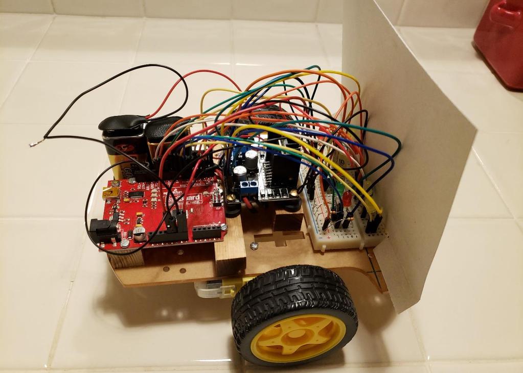
10 2. Open Snap4Arduino and your project and use the Connect Arduino button at the top of the Arduino menu to connect Snap4Arduino to the Arduino board. Retry this step and/or reset the Arduino board if needed (if connection starts but doesn t finish, reset Arduino). 3. Turn on the power to the motor controller board using the switch on the car. 4. Click on the Snap4Arduino green flag to start the motor control script. This script must be running for the motor control keys to work. 5. Then the arrow keys and other keys can be used to operate the car. Remember that the speed control variables do not have any effect on the motors until the arrow keys are pressed. 6. When you are finished, save any changes to your Snap4Arduino scripts, click the Disconnect Arduino button near the top of the Arduino menu, turn off the motor power switch on the car chassis to conserve the battery and disconnect the USB cable. D. Other Components Other Arduino controlled components (e.g., LEDs and sensors) and scripts can be added to enhance the design to be more like a car and/or to detect obstacles in the car s path, etc. However, the basic motor operation uses a lot of Arduino digital pins so the remaining pins must be allocated judiciously. For example, LEDs can be activated directly using the motor control pins to avoid using additional pins for lights. The negative (short) lead of each LED should be connected to ground through a 330-ohm resistor and the positive side of the LED should be connected to the appropriate motor control pins (e.g., Arduino Pins 6 or 7 for Motor 2 in the connection tables above). Connecting LEDs in this manner doesn t change any of the connections in the connection tables; it just connects an LED and resistor in parallel with the motor control pin connection and doesn t require any additional Arduino pins or Snap4Arduino scripts for the LEDs. Using this plan, two LEDs can be used for each motor and one will light when the motor is turning forward and the other will light when it is turning backward as one way to simulate headlights and taillights. An LED and resistor can also be connected to a motor enable pins. The motor will operate normally and the brightness of the LED varies with the motor speed (PWM value). E. Additional Scripts Additional Snap4Arduino scripts can be used to, for example, illustrate the car operation on the stage. Any script like this for an additional sprite really operates separately from the car and does not track it directly but it is an interesting way to combine SNAP and Arduino capabilities. Prototype A photo of my prototype is below. It looks rather messy but this is an effective platform to test the operation, add components and change the Snap4Arduino scripts as needed to test various ideas and configurations and to think about how to better place and mount the boards and components. I used yellow LEDs that light when each motor is moving forward to simulate headlights, red LEDs that light when each motor is moving backward and green LEDs for the motor enables. The wires from the motor controller pins go to the breadboard to connect them to the plus side of the LEDs and also to the wires from the Arduino pins just as if the motor controller pins were connected directly to the Arduino pins. The breadboard is just a convenient place to make this 3-way connection. There is also a ground 10

11 connection from the Arduino board to the breadboard to provide ground for the six resistors for the LEDs. No 5V power connection from the Arduino board to the breadboard is needed for these LEDs because they are powered by the motor controller signals from the Arduino board when they are High. A 5V power connection from the Arduino board can be added for other components if needed. The connection tables and figures above, and the LED connection information in the Other Components section, should be used for the connections rather than looking at wires in the photo below. This photo was taken before the Bluetooth module was added to the breadboard. Connecting the Bluetooth module is described in Addendum 1. 11
12 A prototype like this is too fragile for collisions but it can be used for pulling tests, shallow ramps, running mazes and similar tests. If you add obstacle detectors on each side at the front of the breadboard and the appropriate Snap4Arduino scripts, it could turn or back up to avoid obstacles. Think about what else you d like your car to do and add scripts and components as needed. The Snap4Arduino Arduino blocks can be used to controls Arduino pins connected to LEDs and other components and to read digital and analog pins. Conclusion The project is a low cost and effective project for the Union Pacific Railroad grant. Snap4Arduino is an effective and convenient platform for creating and testing simple programs for this robotic car. The disadvantage, of course, is that the car is connected to a computer by the USB cable but something like a keyboard is needed to control the car operation unless enough sensors are added for automatic driving to avoid obstacles. In any case, Snap4Arduino is an effective way to plan and test the desired operation. Adding a Bluetooth module to the robotic car for wireless communications and control using Snap4Arduino on a laptop or PC is described in Addendum 1. After this wireless operation using Bluetooth is successful, a smartphone can be used to control the car as described in Addendum 2. You can me at AllanT@IEEE.org if you have questions or comments. References Motors and Chassis Kit Chassis-Encoder-wheels- Battery/dp/B00GLO5SMY/ref=sr_1_1?s=industrial&ie=UTF8&qid= &sr=8-1&keywords=emgreat+motor+robot+car+chassis+kit Motor Controller 2. Amazon: Duemilanove/dp/B00CAG6GX2/ref=sr_1_1?ie=UTF8&qid= &sr=8-1&keywords=drok+l298n+motor+drive+controller+board Photoelectric Encoders (if we want to use them probably not, takes more Arduino pins) 5. HC-020K Double Speed Measuring Module with Photoelectric Encoders For Experiment Snap4Arduino
13 Arduino Motor Controller Test Program (continued on next page) Attachment 1 This is a copy of the test program from Reference 3. // connect motor controller pins to Arduino digital pins // motor one int ena = 10; int in1 = 9; int in2 = 8; // motor two int enb = 5; int in3 = 7; int in4 = 6; void setup() { // set all the motor control pins to outputs pinmode(ena, OUTPUT); pinmode(enb, OUTPUT); pinmode(in1, OUTPUT); pinmode(in2, OUTPUT); pinmode(in3, OUTPUT); pinmode(in4, OUTPUT); void demoone() { // this function will run the motors in both directions at a fixed speed // turn on motor A digitalwrite(in1, HIGH); digitalwrite(in2, LOW); // set speed to 200 out of possible range 0~255 analogwrite(ena, 200); // turn on motor B digitalwrite(in3, HIGH); digitalwrite(in4, LOW); // set speed to 200 out of possible range 0~255 analogwrite(enb, 200); delay(2000); // now change motor directions digitalwrite(in1, LOW); digitalwrite(in2, HIGH); digitalwrite(in3, LOW); digitalwrite(in4, HIGH); delay(2000); // now turn off motors digitalwrite(in1, LOW); digitalwrite(in2, LOW); digitalwrite(in3, LOW); digitalwrite(in4, LOW); void demotwo() { // this function will run the motors across the range of possible speeds // note that maximum speed is determined by the motor itself and the operating voltage // the PWM values sent by analogwrite() are fractions of the maximum speed possible // by your hardware // turn on motors 13
14 digitalwrite(in1, LOW); digitalwrite(in2, HIGH); digitalwrite(in3, LOW); digitalwrite(in4, HIGH); // accelerate from zero to maximum speed for (int i = 0; i < 256; i++) { analogwrite(ena, i); analogwrite(enb, i); delay(20); // decelerate from maximum speed to zero for (int i = 255; i >= 0; --i) { analogwrite(ena, i); analogwrite(enb, i); delay(20); // now turn off motors digitalwrite(in1, LOW); digitalwrite(in2, LOW); digitalwrite(in3, LOW); digitalwrite(in4, LOW); void loop() { demoone(); delay(1000); demotwo(); delay(1000); 14
15 Bluetooth Addendum Addendum 1 A. Introduction After the robotic car is constructed and operating successfully using a USB cable, it is relatively easy to replace the USB cable with a wireless Bluetooth connection. The wireless connection permits a wider range of operation for the car and avoids the drag from the USB cable. However, using a Bluetooth connection does add another level of complexity so it is important to have the unit operating with a USB cable before attempting a wireless connection. Bluetooth is a wireless technology for exchanging data over short distances using short-wavelength UHF (ultra-high frequency) radio waves in the ISM (industrial, scientific and medical) band from 2.4 to GHz. Bluetooth transceivers (two-way radios) are included in most laptops and smartphones. Bluetooth connections are low power and relatively short range (compared to WiFi) and they are a good choice for the robotic car. More information on Bluetooth is in References 1 and 2 below but the summary below should be all that is required to use standard Bluetooth modules for Arduino. B. Bluetooth Modules Our testing has been done with two small, low-cost HC-06 Bluetooth modules from Amazon (References 3 and 4). The Solu unit is best for this application because it has a standard, 4-pin female connector which can be plugged directly into an Arduino breadboard. Then connections can be made to the Arduino board as specified below. All these Bluetooth modules must be configured before they are used as described in the Configuration section below. Once this configuration is completed, it remains in the Bluetooth module and does not need to be repeated when power is removed or the module is connected to another Arduino board. This configuration must be done, and StandardFirmata loaded on the Arduino board, before the Bluetooth module is connected to the Arduino board. C. Bluetooth Module Connections The Bluetooth module connections for operation with Standard Firmata and Snap4Arduino are listed in the table below. The Bluetooth module cannot be plugged directly into the Arduino board because it must be connected to pins from both sides so the best plan is to plug the Bluetooth module into the Arduino breadboard and make all the connections on the breadboard where 5V and GND are already available for other components. Note that the Transit and Receive connections are crossed between the Bluetooth module and the Arduino board (Transmit connected to Receive and Receive connected to Transmit). Bluetooth Module Arduino Comments VCC 5V Bluetooth Module Power GND GND Bluetooth Module Ground TX (Transmit) Pin 0 RX (Receive) Transmit and Receive connections RX (Receive) Pin 1 TX (Transmit) must be crossed These connections are shown in the illustration below (to simplify this figure, the Motor Controller and LED connections are not shown but they are still connected). 15

16 D. Power Alternatives The USB cable was used to power the Arduino board for the robotic car but now another source of power is needed for the Arduino board for wireless operation. There are two good alternatives: 1. Connect a 9V battery to the Arduino board phono plug or to VIN as shown above, with a switch so the power can be turned off easily, or 2. Connect the unused +5V Out terminal on the Motor Controller board to VIn on the Arduino board (VIn is next to the two GND pins in the POWER section). The Arduino GND is already connected to the Motor Controller GND for standard USB operation above. This alternative should work OK but the life of the single battery will be somewhat shorter. E. Bluetooth Robotic Car Operation After the Bluetooth Module is configured and connected to the Arduino Board with StandardFirmata loaded, the steps to operate the robotic car are: 1. Turn on the power to the Arduino board. Power to the motor controller board can be turned on later if it has a separate battery. The red LED on the Bluetooth module should be flashing. If not, check the connections. 2. Pair the Bluetooth module to the laptop or PC if this has not already been done (see the Configuration section below for details). If the Bluetooth module appears on the PC with just the name HC-06, it has not been configured and must be configured before it is used. 3. Open Snap4Arduino and your project and use the Connect Arduino button at the top of the Arduino menu to connect Snap4Arduino to the Arduino board. Two COM ports will be visible for the Bluetooth connection. Try the lower one first. Retry this step and/or reset the Arduino board if needed (if connection starts but doesn t finish, reset Arduino). No changes to the Snap4Arduino programs are needed because the Bluetooth connection simply replaces the USB cable serial connection. 16
17 4. Turn on power to the motor controller board if not done in Step 1 above. 5. Click on the Snap4Arduino green flag to start the motor control script. This script must be running for the motor control keys to work. 6. Then the arrow keys and other keys can be used to operate the car. Remember that the speed control variables do not have any effect on the motors until the arrow keys are pressed. 7. When you are finished, save any changes to your Snap4Arduino scripts, click the Disconnect Arduino button near the top of the Arduino menu and turn off the motor power switch on the car chassis to conserve the battery. Power to the Arduino board can also be turned off if it has a separate battery. F. Bluetooth Module Configuration and Pairing The Bluetooth module must be configured before it is used for the robotic car or other applications. Once this configuration is completed, it remains in the Bluetooth module flash memory and does not need to be repeated when power is removed or the module is connected to another Arduino board. The first step is to connect the Bluetooth module to an Arduino board that will be used for the configuration as shown in the table below. This is not the same connections used by the car operation above and the Arduino board used for the robotic car should not be used for this step because different Arduino software will be loaded. The Arduino board must be connected to a computer by a USB cable for this step. Pins 0 and 1 cannot be used on the Bluetooth module for the configuration because using them would interfere with the USB serial communications. Only the Bluetooth module should be connected to the Arduino board while configuring. Bluetooth Module Configuration Connections Bluetooth Module Arduino Comments VCC 5V Bluetooth Module Power GND GND Bluetooth Module Ground TX (Transmit) Pin 10 RX (Receive) Transmit and Receive connections RX (Receive) Pin 11 TX (Transmit) must be crossed The LED on the Bluetooth module should be flashing red as soon as you connect the power. If not, check the connections in the table above. Next, load the configuration software below on the Arduino board: 17
18 Bluetooth Module Configuration Script #include <SoftwareSerial.h> SoftwareSerial BTSerial(10, 11); // TX RX void setup() { Serial.begin(9600); Serial.println("Enter AT commands:"); BTSerial.begin(9600); // Bluetooth serial port data rate (change if needed) void loop() { // Keep reading from HC-06 and send to Arduino Serial Monitor if (BTSerial.available()) Serial.write(BTSerial.read()); // Keep reading from Arduino Serial Monitor and send to HC-06 if (Serial.available()) BTSerial.write(Serial.read()); Then open the serial monitor from the Arduino IDE by either pressing Control+Shift+M or by choosing the Serial Monitor option from the Tools menu. In the serial monitor window, be sure that the baud rate is set at 9600 baud and select No line ending at the bottom. Next, enter the command AT in the text input box at the top, and either press the Enter key or click on Send. You should receive OK back from the board on the serial monitor which means that the module is ready to receive your commands. If not, check the connections and that the program has been properly loaded on the Arduino board. The next step is to name the Bluetooth module. This step sets the name that will show up when you scan for the Bluetooth module for pairing below. It is essential to perform this step so no two modules in the STEM Workshop have the same name. To set its name to WHATEVER you just need to send it the following command: AT+NAMEWHATEVER. If all goes well, the module should respond with OKsetname. For the STEM Workshop, enter the command AT+NAMEWSHC_06-xx, where xx is the next number to be used. Start with xx = 03 because 01 and 02 have already been used. Enter or Send and you should receive OKsetname which may be on the same line as the OK received above and not separated from it by a space. Now we need to set up the speed at which the Bluetooth module and Snap4Arduino should communicate with each other. Snap4Arduino requires a baud rate of 57600, and the AT command that sets the module to this speed is AT+BAUD7 to which the module should respond with OK Again, this may be on the same line as OKsetname so the line is now OKOKsetnameOK This last step sets the default Bluetooth module communication speed to baud as required for Snap4Arduino even though the connection for the configuration is operating at 9600 baud. 18
19 If any configuration problems are encountered, follow the more detailed instructions in Reference 5 below. To pair the Bluetooth module to a PC, following the standard Bluetooth pairing procedure. In Windows 10, open Settings, the Devices, then Bluetooth and other devices, turn on Bluetooth if it is not already on and then select Add Bluetooth or other device at the top. Then select Bluetooth and the computer will scan for available devices. Select the device name and it should say Connecting. Enter the passcode 1234 when prompted (the passcode is the same for all HC-06 modules). The computer should respond that it is paired. The procedure is similar for older versions of Windows. Again, follow the more detailed instructions in Reference 5 below if needed. G. Bluetooth Dongles for Laptops or PCs Without Bluetooth Bluetooth dongles which plug into USB ports can be used for older laptops or PCs which don t have Bluetooth capabilities. Two highly-rated units are References 6 and 7 below. They should install automatically on recent versions of Windows. Additional software may be needed for older versions of Windows. After they have been installed, these units can be paired with Arduino Bluetooth modules using the paring procedure outlined just above or similar procedures for older PCs or laptops. The dongles can also be used for other Bluetooth connections (keyboards, etc.). One of our challenges was to add Bluetooth capabilities to older Windows 7 Workshop laptops without Bluetooth. An Advantree dongle (Reference 6) was used to test adding this capability. The dongle should be installed following the instructions and using the software on the CD provided with this unit. After the installation is complete and the laptop has been restarted, the Bluetooth BlueSoleil Space icon on the desktop can be used to access the Bluetooth capabilities. Double click the orange globe in the center of the BlueSoleil window to see the Bluetooth devices detected by the laptop. Right click on a Bluetooth device and select Pair. Enter the passcode, which is 1234 for these HC-06 Bluetooth modules used for the Arduino robotic cars. Then, back on the BlueSoleil window, right click on the Bluetooth device to search services and connect (this is an extra step not required for PCs or laptops with Bluetooth capabilities). Note the COM port used for the connection. Then you should be able to open Snap4Ardino and use that COM port to connect wirelessly using the dongle and the Arduino Bluetooth module as described in this addendum above. The PC or laptop should retain these settings but, if problems are encountered, repeat the steps in this section to be sure the paring and connecting are OK following this sequence: 1. Pair the Bluetooth dongle on the laptop with the Arduino Bluetooth module if they are not already paired. 2. Connect the Bluetooth dongle on the laptop with a laptop COM part using the BlueSoleil window. 3. Then you should be able to make the wireless connection between the Bluetooth dongle on the laptop and the Arduino Bluetooth module using Snap4Arduino. 19
20 H. Conclusion A Bluetooth wireless connection permits a wider and more flexible range of operation for the car and avoids the drag from the USB cable. However, it does add another level of complexity so it is important to have the unit operating with a USB cable before attempting a wireless connection. After this wireless operation using Bluetooth is successful, a smartphone can be used to control the car as described in Addendum 2. I. Bluetooth References Solu JY-MCU HC-06 Slave Bluetooth Serial Port Transceiver Baseboard Mini module// Arduino Wireless Bluetooth Transceiver Module Slave 4Pin Serial ( 8&psc=1) 4. KEDSUM Upgraded Arduino HC-06 Serial Bluetooth Slave Wireless RF Transceiver Module with DuPont Cable ( &psc=1) Keyboard/dp/B00VWEK4IG/ref=sr_1_1_sspa?ie=UTF8&qid= &sr=8-1- spons&keywords=bluetooth+usb+module+mini&psc=1&smid=a1c41w6v7r1eva 7. Compatible/dp/B009ZIILLI/ref=sr_1_2_sspa?ie=UTF8&qid= &sr=8-2- spons&keywords=bluetooth+usb+module+mini&psc=1 20

21 Smartphone Operation Addendum Addendum 2 A. Introduction After the robotic car is operating successfully with a Bluetooth module as described in Addendum 1, the next question is can we use a smartphone to control the car via Bluetooth rather than using a laptop or PC? The answer is yes; an app is available with a controller mode and convenient buttons and it is not too difficult to write the Arduino program needed for the robotic car operation. I also looked for ways to use Snap4Arduino on a tablet or smartphone but I haven t found a way that works well yet and, on a smartphone, there are not any convenient buttons like arrows so writing an Arduino program for use with an available app seems to be the best alternative. B. Arduino Bluetooth Controller App I chose the Arduino Bluetooth Controller app (Reference 1) for the robotic car because it is highly-rated and has a Controller Mode with appropriate buttons to operate the car. The arrow buttons can be used for motor direction, START can be used to start and stop the motors and the buttons on the right (triangle, X, O, square) can be used for other purposes (e.g., to control the speed of the motors). With the appropriate Arduino program modifications, SELECT can be used to change the meaning of the buttons on the right to add additional features (see below). WSHC_06-02 in the screenshot above is the name of the Arduino Bluetooth module the Arduino Bluetooth Controller app is paired and connected to. Assigning the Arduino Bluetooth Controller app Controller mode button to digits to the sent to Arduino via the Bluetooth module is easy. Just touch the settings gear, select a button, assign a number and touch Done on the keyboard to complete the assignment. Repeat for the other buttons. More detail is in Reference 2 if needed. The button assignments I used are in the table below and these assignments 21
22 should be followed to use the Controller mode with the Arduino Program below. These settings are retained by Arduino Bluetooth Controller app and do not need to be reset each time it is used. Arduino Bluetooth Controller (ABC) App Controller Mode Button Assignments ABC Button Assignment Purpose Up arrow 1 (49) Set Both Motors Forward and Start Motors Down Arrow 2 (50) Set Both Motors Backward and Start Motors Left Arrow 3 (51) Turn Left (Left Motor Back, Right Motor Forward), Start Motors Right Arrow 4 (52) Turn Right (Right Motor Back, Left Motor Forward), Start Motors Select 5 (53) Select alternatives features for 4 right buttons Start 6 (54) Start/Stop (Turn Off both motors, Push again to turn On both Motors) Triangle (Gray) 7 (55) Increase Speed Motor 1 by 10% to 100% Maximum X (Orange) 8 (56) Decrease Speed Motor 1 by 10% to 0% Minimum O (Green) 9 (57) Increase Speed Motor 2 by 10% to 100% Maximum Square (Red) 0 (48) Decrease Speed Motor 2 by 10% to 0% Minimum The first numbers (1-0) in the Assignment column in the table above are the numbers assigned to the button in the Arduino Bluetooth Controller app Controller mode. The second numbers in parentheses (49-48) are the ASCII code that will be transmitted to Arduino by the Arduino Bluetooth Controller app (see Reference 3). Note that the first number is always 48 less that the second number (because 0 is ASCII 48). The ASCII codes will be converted back to the Arduino Bluetooth Controller app assignments in the Arduino programs below. I did all my testing with the Android Arduino Bluetooth Controller app on a recent Samsung phone. I would expect other Android phones and tablets to work the same way. I don t see a version of this app for iphones in the iphone app store but I would expect other available apps to work in a similar fashion. C. Arduino Program After the robotic car is operating successfully with a Bluetooth module as described in Addendum 1, it is relatively easy to write an Arduino program following the Snap4Arduino scripts with a few changes because the Arduino Bluetooth Controller app Controller mode buttons will the touched rather than held down like the arrow keys on a laptop or PC keyboard. The primary differences are: 1. Buttons on a touch screen like a smartphone are activated when the fingertip or stylus are raised from the smartphone screen. Nothing happens when a button is help down until the fingertip or stylus is raised above the surface so smartphone buttons must be tapped rather than help down. 2. The arrow buttons in the Arduino Bluetooth Controller app Controller mode set the directions for the motors and enable the motors at the current speed. If the motors are stopped, these buttons start the motors. If the motors are running, the motors continue to run with changes in direction determined by the key touched. 3. If the forward or backward button is activated, the car will move forward or backward continuously until the direction is changed or the motors are stopped. However, continuous operation doesn t work for turns because the car will just turn in circles. Therefore, with the Arduino program below, the left and right turn arrows are momentary operations for one cycle of 100 milliseconds (which can be adjusted) and then the car resumes moving in the previous 22
23 direction (forward or backward). Tapping the left or right turn buttons repeatedly will make the car turn more and then continue in the previous direction. 4. Touching the START button again will start or stop both motors. The motors are usually running from previous direction or speed actions so this button is usually used first to stop the motors. Touching the START button when the motors are stopped will start both motors at the current direction and speed settings. 5. The SELECT button is used to change the meaning of the buttons on the right to add additional features (see below). If the SELECT button hasn t been touched, or if is used to cycle back to 0, the buttons at the right increase or decrease the speed settings for the motors. The Arduino program includes statements to display the digits received from the Arduino Bluetooth Controller app and to indicate the actions taken by the Arduino program. The USB cable must be connected to see the display on the Serial Monitor and this is a very convenient way to verify that everything is working as expected and to debug any problems. Arduino serial monitor display examples are Section E below. The Arduino program also flashes the LED on Arduino Pin 13 as each action is taken and this indicates that the Arduino Bluetooth Controller app is communicating with the Arduino board when the USB cable is not connected. The Serial Monitor must be set to baud at the lower right because that is the Bluetooth speed required for Snap4Arduino and the speed we set the Bluetooth modules to use. The Arduino program starts with three motor control function definitions much like the Snap4Arduino program above. However, these functions are more complicated because they can each be used to control either motor and because they need to include Arduino serial monitor display statements. The only thing unusual about this Arduino program is that it uses a switch case statement (Reference 4) because that is a convenient way to execute different sections of code for each Arduino Bluetooth Controller app Controller button. Like if statements, switch case controls the flow of programs by allowing programmers to specify different code that should be executed in various conditions. The switch statement compares the value of a variable to the values specified in case statements. When a case statement is found whose value matches that of the variable, the code in that case is executed. The final Arduino program is in Attachment 1 to Addendum 3 below but it is better to download it from our website at than to copy it from here or try to type it in the Arduino IDE. The version for just the smartphone operation without the obstacle detection (Addendum 3) can also be downloaded from our website because it is easier to understand than the final version and may be useful for testing at this stage. However, the final version should also run OK without the obstacle detector. Remember that the Tx and Rx connections from the Arduino board to the Bluetooth module must be disconnected when an Arduino program is uploaded and restored after the uploading is complete so the Bluetooth and USB serial communications don t interfere with each other. The Transit and Receive connections must be crossed between the Bluetooth module and the Arduino board (Transmit connected to Receive and Receive connected to Transmit). 23
24 D. Smartphone Operation Assuming the Bluetooth Module is configured and connected to the Arduino Board, and the Arduino program described above has been loaded, the steps to operate the car using the smartphone are: 1. Turn on the power to the Arduino board. Power to the motor controller board can be turned on later if it has a separate battery. The red LED on the Bluetooth module should be flashing. If not, check the connections. 2. Pair the Bluetooth module to the smartphone if this has not already been done (see the Bluetooth Configuration section above for details). If the Bluetooth module appears on the smartphone with just the name HC-06, it has not been configured and must be configured before it is used. 3. Open the Arduino Bluetooth Controller (ABC) app on the smartphone and select the name for the Bluetooth module for your car. The ABC app will connect and open a screen to select the ABC app mode. Select the Controller mode. 4. Turn on power to the motor controller board if not done in Step 1 above. 5. Use the ABC app arrow buttons and other buttons to control the operation of the car as described above. Use the START button to start or stop the motors. The speed control changes take effect immediately now when the speed controls are pressed. There is a small delay in the Arduino program loop so only one button code is acted on by the Arduino board when buttons are pressed. 6. If the USB cable is still connected and the Arduino Serial Monitor is open and set to baud as described above, the digits received from the ABC app and the operations executed by the Arduino program will be displayed on the Serial Monitor. This capability should be used to test and debug the operation of your car. See the table below for Arduino Serial Monitor examples. When the USB cable is not connected, the LED flashes on Pin 13 of the Arduino board indicate that the smartphone and Arduino are communicating. 7. When you are finished, push the back button on the navigation panel of your smartphone to disconnect and turn off the motor power switch on the car chassis to conserve the battery. Power to the Arduino board can also be turned off if it has a separate battery. E. Arduino Serial Monitor Display Arduino Serial Monitor examples are shown in the table below. The first line of each group of two to four lines is the ASCII digits received from the Arduino Bluetooth Controller (ABC) app followed by the ABC action digits calculated in the Arduino program and the button touched. The remaining lines of each group are the action(s) executed by the Arduino program. The Arduino program does not let motor speeds increase beyond 100% or decrease below 0%. The Arduino program receives only the ASCII digits from the ABC app. All the testing and debugging communications to the serial monitor are generated by the Arduino program. Sharp left and right turns are included in the table below. Slower turns can be done to increasing or decreasing the speed of one motor using the speed control buttons. 24
25 Arduino Serial Monitor Display for Testing Setup completed, Bluetooth Serial Communication at baud 49, ABC Action 1, Up Arrow Motor 1 Forward at 50% Motor 2 Forward at 50% 50, ABC Action 2, Down Arrow Motor 1 Backward at 50% Motor 2 Backward at 50% 49, ABC Action 1, Up Arrow Motor 1 Forward at 50% Motor 2 Forward at 50% 51, ABC Action 3, Left Arrow Motor 1 Backward at 50% Motor 2 Forward at 50% Motor 1 Forward at 50% 52, ABC Action 4, Right Arrow Motor 1 Forward at 50% Motor 2 Backward at 50% Motor 2 Forward at 50% 54, ABC Action 6, START(STOP) Motor 1 Stopped Motor 2 Stopped 54, ABC Action 6, START Both motors started at M1 50%, M2 50% 55, ABC Action 7, Triangle Motor 1 speed set to 60% 56, ABC Action 8, X Motor 1 speed set to 50% 57, ABC Action 9, O Motor 2 speed set to 60% 48, ABC Action 0, Square Motor 2 speed set to 50% 55, ABC Action 7, Triangle Motor 1 speed set to 60% 55, ABC Action 7, Triangle Motor 1 speed set to 70% 55, ABC Action 7, Triangle Motor 1 speed set to 80% 55, ABC Action 7, Triangle Motor 1 speed set to 90% 55, ABC Action 7, Triangle Motor 1 speed set to 100% 55, ABC Action 7, Triangle Motor 1 speed set to 100% 48, ABC Action 0, Square Motor 2 speed set to 40% Comments Communication started (this all prints on one line) ASCII digits received, ABC action, button touched Arduino program actions executed Both motors Forward Both motors Backward Both motors Forward again Sharp left turn Motor 1 Backward to start turn No effect because Motor 2 is already Forward Motor 1 Forward after delay to stop turning Sharp right turn No effect because Motor 1 is already Forward Motor 2 Backward to start turn Motor 2 Forward after delay to stop turning Start button touched to stop motors which were started by the actions above Restart both motors in current direction and at current speed Increasing Motor 1 speed Decreasing Motor 1 speed Increasing Motor 2 speed Decreasing Motor 2 speed Increasing Motor 1 speed Increasing Motor 1 speed Increasing Motor 1 speed Increasing Motor 1 speed Increasing Motor 1 speed Increasing Motor 1 speed (does not go beyond 100% maximum) Decreasing Motor 2 speed 25
26 Arduino Serial Monitor Display for Testing 48, ABC Action 0, Square Motor 2 speed set to 30% 48, ABC Action 0, Square Motor 2 speed set to 20% 48, ABC Action 0, Square Motor 2 speed set to 10% 48, ABC Action 0, Square Motor 2 speed set to 0% 48, ABC Action 0, Square Motor 2 speed set to 0% 53, ABC Action 5, SELECT Select = 1 55, ABC Action 7, Triangle Select = 1, new feature can be added here 56, ABC Action 8, X Select = 1, new feature can be added here 57, ABC Action 9, O Select = 1, new feature can be added here 48, ABC Action 0, Square Select = 1, new feature can be added here 53, ABC Action 5, SELECT Select = 0 Comments Decreasing Motor 2 speed Decreasing Motor 2 speed Decreasing Motor 2 speed Decreasing Motor 2 speed Decreasing Motor 2 speed (does not go below 0% minimum) Select changes meaning of right buttons New features can be added to Arduino program Touch Select again to change speeds Note that new features can be added to the Arduino program and SELECT can be used to activate these features. Select could also have additional values to add more than four new features. F. Reliability and Adjustments The robotic car operation with a smartphone in the STEM Workshop was not completely reliable, perhaps due to RF (radio frequency) interference from other computers and equipment or simply from the voltage variations resulting from starting and reversing the directions of the car motors. I solved this problem by using two 9V batteries, one for the motors and the other for the Arduino board and other components. This solution has the advantage that, with two switches, the operation of the Arduino board and other components can be tested and debugged without the motors running. All the grounds must be connected together. Two batteries cannot be connected to the same SPST (single-pole, singlethrow) switch. Another way to resolve voltage variation problems, which I didn t test for the car, is to use a capacitor to suppress noise and absorb the voltage variations. The delay at the end of the Arduino program is set to 100 milliseconds (0.1 seconds). Setting it to a higher value (e.g., 200 milliseconds) will make the car turn more when the left and right turn buttons are touched but some repeated taps may be missed. Setting it to a lower value (e.g., 50 milliseconds) will minimize missing repeated taps but the car will turn less when the turn buttons are touched. 26
27 G. Conclusion It works! An Android smartphone can be used to control the robotic car when the USB cable is disconnected. And, if the USB cable is connected, the Arduino Serial Monitor can be used to monitor and test the operation of the car by the smartphone. Additional features can be added to the car and the Arduino program and controlled by the Arduino Bluetooth Controller app on the smartphone. H. Smartphone References 1. Arduino Bluetooth Controller: ASCII Codes: 4. Arduino Switch Case: 27

28 Obstacle Detection Addendum Addendum 3 A. Introduction Wouldn t it be nice if the robotic car could detect obstacles in its path and do something by itself to avoid them (e.g., stop)? To do that, we ll need a way to detect obstacles, measure the distance and take some action to avoid collisions. If it works, this can be the start of an autonomous robotic car that can make decisions on its own and take appropriate action. This is a simple form of artificial intelligence implemented using Arduino code. Of course, we ll need to have a way to warn the user that there is an obstacle in the path of the car and that the car has decided to do something if the user doesn t steer the car away from the obstacle. There are several ways to detect obstacles and measure the distance. We ll start with an ultrasonic detector that uses sound waves at a higher frequency that humans can hear because good, inexpensive ultrasonic detectors are available for this purpose. Infrared detectors are also available. Other ways to detect obstacles and measure the distance include radar and lidar (like traffic speed detectors). Using ultrasonic sound waves to detect obstacles is a kind of sonar even though we usually use that term for underwater detection and ranging rather than sound waves in the air. Animals that use sound waves in the air to detect obstacles include bats so, if this works, we can call our car the bat car. B. Ultrasonic Detector The SparkFun HC-SR04 Ultrasonic Sensor (Reference 1) is a good, inexpensive ultrasonic detector. This sensor can measure from 2 cm (centimeters), which is about ¾ of an inch, to 400 cm, which is 4 meters or just over 13 feet, with a ranging accuracy up to 3 mm (millimeters). The HC-SR04 module includes an ultrasonic transmitter, a receiver and a control circuit. When triggered, the module sends eight 40 khz sound waves and then detects any pulse signal echo. It operates on 5V DC so it is compatible with Arduino but its measurement angle is only 15 degrees so two or three modules may be required to detect and avoid all obstacles in front of the car. We ll start with one module to see how it works. C. Ultrasonic Detector Arduino Test Program We ll use an Ultrasonic Detector Arduino test program to test our sensor and see what it can measure and how it works before we try to integrate it into the Arduino program for the robotic car. This test program will introduce several Arduino capabilities and commands that you may not have used before: 1. Arduino compiler preprocessor constants Arduino compiler preprocessor constants (Reference 2) can be used to define constants that are replaced by the Arduino compiler and thus don t take any Arduino memory space. They are used in this test program to define the pins used by the Ultrasonic Sensor. 28
29 2. Long (big) variables Long variables (Reference 3) are extended size variables, from -2,147,483,648 to 2,147,483,647, that use 32 bits (4 bytes) in Arduino memory. We ll need long variables to store big numbers like the duration (time) for the echo pulse to return to the ultrasonic sensor and the distance that duration represents. 3. pulsein() pulsein() (Reference 4) is an Arduino command to read a pulse (either HIGH or LOW) on a pin. For example, if value is HIGH, pulsein() waits for the pin to go HIGH, starts timing, then waits for the pin to go LOW and stops timing. It returns the length of the pulse in microseconds or returns 0 if no pulse starts within a specified timeout. The default for the timeout is 1 second (1,000,000 microseconds) so we ll need to use a shorter timeout for our Arduino program because 1 second corresponds to about 564 feet and our sensor s maximum range is about 13 feet. Even 13 feet is too much for our car because it would always be detecting obstacles so we ll set the maximum range in our program to 3,550 microseconds which corresponds to about 61 cm or 2 feet. And we ll plan to take action (stop) when the distance is 10 cm, which is a little less than 4 inches. All of these parameters can be adjusted to enhance the car operation. 4. Timing considerations When triggered by a 10 microsecond high on the trigger pin, the ultrasonic module sends a pulse of eight 40 khz sound waves and the Arduino program then uses pulsein() to detect any pulse signal echo. The pulsein() timeout of 3,550 microseconds (3.55 milliseconds) is, fortunately, short compared to the cycle time of 100 or 200 milliseconds for the Arduino robotic car program to cycle through its loop to receive commands from the smartphone controller app and execute them. Therefore, the ultrasonic detector timing shouldn t have significant effect on the car operation but we will want to observe this carefully later to confirm this conclusion. D. Ultrasonic Detector Connections Even though we re testing the HC-SR04 Ultrasonic Sensor operation using a separate Arduino board that is not connected to the robotic car, let s use Arduino pins that aren t used for the robotic car so they don t have to be changed later to integrate this code into the robotic car program. Arduino and SC-SR04 Connections Arduino Pins HC-SR04 Pins Purpose 12 Trig Trigger to transmit the 40 khz sound waves 11 Echo Receive the echo using pulsein() 5V VCC Power for HC-SR04 module (Breadboard + rail) GND GND Ground for HC-SR04 module (Breadboard - rail) Other Connections Arduino Pins LEDs Purpose 4 Blue LED+ Trigger pulses 3 Yellow LED+ HC-SR04 module has detected an obstacle 2 Red LED+ Obstacle is close and Arduino program is taking action GND GND Ground for LEDs through 330-ohm resistors* * A separate 330-ohm resistor to ground (Breadboard - rail) should be connected to each negative LED lead. 29

30 The Other Connections above aren t required for the Ultrasonic Sensor operation. They are used to help debug and visualize the sensor operation and can be removed later if the Arduino pins are needed for other purposes. The connections above are shown in the illustration below (to simplify this figure, the Motor Controller and its LED connections, and the Bluetooth Module connections, are not shown but they are still connected). E. Ultrasonic Detector Testing When everything is connected, we can upload the Arduino test program (Attachment 1 to this addendum) to the Arduino test board and observe the operation. The blue LED should start blinking immediately after the upload to indicate that the 40 khz sound waves are being transmitted. The yellow LED should light when an object (e.g., your hand) is placed within about two feet of the ultrasonic detector. The red LED should light when the object is moved to within about 4 inches of the detector. Check the wiring and be sure the Arduino test program uploaded properly if the LEDs don t light when they should. Open the Arduino Serial Monitor, set it at 9,600 baud and observe the reports as you move your object or hand so you can correlate the operation and measurements. I found that the out of range transition occurs at about 49 cm to 50 cm (about 20 inches) rather than the 61 cm calculated above. It doesn t have to be very accurate for the robotic car and this is close enough that I didn t spend time fine tuning the parameters. The robotic car is about 6 wide and the ultrasonic sensor has a measurement angle of 15 degrees. Let s calculate the distance x at which the car should be able to detect an object that is off the centerline of the car by ½ the width of the car as illustrated in the drawing below. The shaded area is ½ of the ultrasonic sound wave which is a 7.5 degree angle. Using a triangle calculator (Reference 5), we see that, if ½ of the car width is 3 inches, the distance x is inches. This, coincidentally, is just a little more that the 20 inches for the out of range transition noted above. 30
31 Top view of robotic car width and sound wave 7.5-degree angle X = inches Object B 3 inches Object A This means we should be able to detect Object A at about ½ the width of the car (or a little less) but we will not be able to detect Object B if it is within ½ of the width of car but too close to the car to be in the sound wave. Object B could get in this position either because the car is driving toward an object is has previously detected or because the car has turned right toward Object B or because Object B has moved to that position (e.g., it is crossing in front of the car). You can observe this angle with your car by moving your hand or an object in front of the car and away from the centerline until it is just detected by ultrasonic sensor. Then move you hand or object closer to the car on the same distance from the centerline and observe that it is not detected. Your results may vary because the object (for example, Object A) is reflecting only a very small part of the sound wave back to the echo detector or because some of the sound wave is absorbed by the object or reflected away from the detector (e.g., a triangular rather than a rectangular object). Also note that the car, including the wheels, is almost 7 inches wide rather than the 6 inches used for the calculation above. There are two possible solutions to detect objects more reliably with a sensor that has a narrow measurement range: 1. Use more sensors. For example, put one sensor perpendicular to the center line and two more sensors pointed 15 degrees to the left and right of the centerline. Then the combined measurement angle would be about 45 degrees which is much better than just 15 degrees. And the echoes for the left and right sensors could be used to determine which direction to turn. 2. Mount the ultrasonic sensor on a servo so it can sweep back and forth in front of the car. This solution only takes one sensor. The sensor would only detect objects when it is pointing toward them and the servo angle could be used to determine which direction to turn. Let s get the car working with one sensor and observe the operation before we worry about this measurement angle problem. Both solutions suggested above would complicate the Arduino code and take more Arduino pins than we have available. However, it may be possible to trigger three sensors at the same time with one Arduino pin if the returning echoes don t interfere with each other. Some comments on the HC-SR04 Ultrasonic Sensor web pages suggest that we should be careful using an ultrasonic transmitter like this around animals like dogs and cats which can hear at higher frequencies than we can. I don t believe this is a real problem at this frequency. Our cat and dog don t appear to hear or be affected by the ultrasonic waves. The sensor detects our furry, black cat very nicely when he walks in front the sensor. He doesn t look toward it like he is hearing it and he doesn t do anything to avoid it. 31
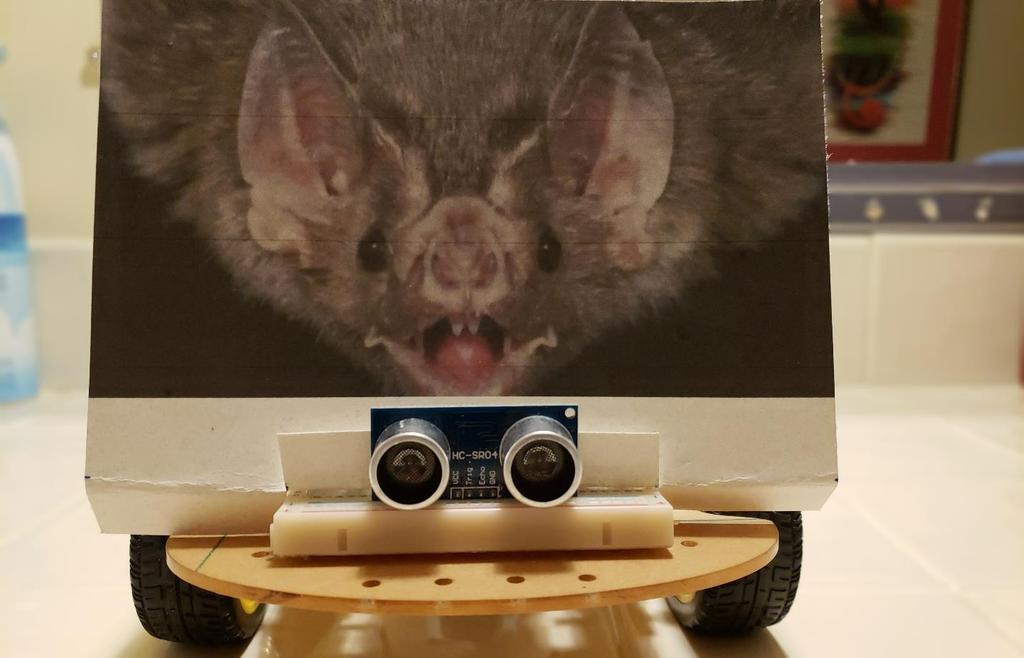
32 F. Robotic Car Arduino Code Integration Once we are satisfied that the HC-SR04 Ultrasonic Sensor is operating properly with the test program, we need to integrate pieces of the test program into the Arduino code for the robotic car in the right places and add some code to control what the car does when an obstacle is detected. Let s also have a way to turn the sensor on and off from the smartphone app. We ll also need a way to limit the measurement reports on the serial monitor so we can see the car operation messages without too many measurement reports overwhelming them. I limited the reports so only one measurement is reported until the measurement changes or there are ten detections of the same measurement. To integrate pieces of the test program into the Arduino code for the robotic car, we can divide the test code into three sections: 1. The Arduino compiler preprocessor constants and the variables before the setup() statement. These constants and the variables will go in similar places in the Arduino code for the robotic car. 2. The setup pinmode statements. These statements will go in the setup section in the Arduino code for the robotic car. 3. The statements in the loop section of the test program. These statements go in the loop section of the Arduino code for the robotic car but this is a long section and it is less obvious where to put them. I chose to put them in a separate group after the robotic car code finishes looking for new smartphone commands via Bluetooth and executing those commands and just before the delay for the next cycle through the loop. Placing them here makes them less like to affect the Bluetooth communications and the car operation timing. It shouldn t affect the car operation if the overall loop timing varies a bit due to the ultrasonic sensor code variations. I also added some code to stop the car when the red LED for the ultrasonic sensor if turned on and to limit the measurement reports on the serial monitor so we can see the car operation messages without too many measurement reports overwhelming them. The car can be restarted by backing away from the obstacle, which it can do even if the obstacle is within the stopping distance. The obstacle detection will usually stop the motors again if you try to go forward or turn. I put the statements in the loop section of the test program under an if statement in the robotic car code so they won t execute if the ultrasonic sensor is turned off, which is the default mode. But how do we turn it on? We can use one of the buttons on the right side of the smartphone app that we designed to accommodate new features when the select button is touched. This is a good example of the way new features can be integrated into the robotic car code without major changes. Now we can touch Select and then then gray triangle button (case 7) to turn on the ultrasonic sensor and touch this button again to turn it off (while Select is 1 or when it has been set back to 1 after speed changes). My final Arduino program is in Attachment 2 below but it is better to download it from our Website at than to copy it from here or try to type it in the Arduino IDE. 32
33 G. Robotic Car Obstacle Detection Testing Finally, we re ready to test the robotic car with the new Arduino code and the smartphone app. We ll just be sure the Bluetooth Rx and Tx wires are disconnected, upload the new code, set the serial monitor to 57,600 baud and reconnect the Bluetooth Rx and Tx wires. Since the ultrasonic sensor default mode is off, we can first test that the car operation with the smartphone app appears to be much like it was before these changes. Then we can touch Select and the gray triangle to turn the ultrasonic sensor on. The blue LED should start blinking and we can observe the obstacle detection LEDs and the serial monitor to see if we are satisfied with the operation. If not, the various parameters (constants) that affect the car and obstacle detector operation can to adjusted to enhance the operation. Then disconnect the USB cable and operate the car from a smartphone. The final version of my car with the ultrasonic detector is shown in the photos below. A photo from Reference 6 reminds us how much more we d need to do to approach the capabilities of a real bat. H. Conclusion We now have a way to warn the user that there is an obstacle in the path of the car and the car can decide by itself to do something if the user doesn t steer the car away from the obstacle. This is the start of an autonomous robotic car that can make decisions on its own and take appropriate action using a very simple form of artificial intelligence implemented in Arduino code. I. References
34 34
TA0139 USER MANUAL ARDUINO 2 WHEEL DRIVE WIRELESS BLUETOOTH ROBOT KIT
 TA0139 USER MANUAL ARDUINO 2 WHEEL DRIVE WIRELESS BLUETOOTH ROBOT KIT I Contents Overview TA0139... 1 Getting started: Arduino 2 Wheel Drive Wireless Bluetooth Robot Kit using Arduino UNO... 1 2.1. What
Note. The above image and many others are courtesy of - this is a wonderful resource for designing circuits.
 Robotics and Electronics Unit 2. Arduino Objectives. Students will understand the basic characteristics of an Arduino Uno microcontroller. understand the basic structure of an Arduino program. know how
Section 3 Board Experiments
 Section 3 Board Experiments Section Overview These experiments are intended to show some of the application possibilities of the Mechatronics board. The application examples are broken into groups based
How-To #3: Make and Use a Motor Controller Shield
 How-To #3: Make and Use a Motor Controller Shield The Arduino single-board computer can be used to control servos and motors. But sometimes more current is required than the Arduino can provide, either
StenBOT Robot Kit. Stensat Group LLC, Copyright 2018
 StenBOT Robot Kit 1 Stensat Group LLC, Copyright 2018 Legal Stuff Stensat Group LLC assumes no responsibility and/or liability for the use of the kit and documentation. There is a 90 day warranty for the
Halloween Pumpkinusing. Wednesday, October 17, 12
 Halloween Pumpkinusing Blink LED 1 What you will need: 1 MSP-EXP430G2 1 3 x 2 Breadboard 3 560 Ohm Resistors 3 LED s (in Red Color Range) 3 Male to female jumper wires 1 Double AA BatteryPack 2 AA Batteries
University of Hull Department of Computer Science C4DI Interfacing with Arduinos
 Introduction Welcome to our Arduino hardware sessions. University of Hull Department of Computer Science C4DI Interfacing with Arduinos Vsn. 1.0 Rob Miles 2014 Please follow the instructions carefully.
Rover 5. Explorer kit
 Rover 5 Explorer kit The explorer kit provides the perfect interface between your Rover 5 chassis and your micro-controller with all the hardware you need so you can start programming right away. PCB Features:
AlphaBot2 robot building kit for Arduino
 AlphaBot2 robot building kit for Arduino SKU 110060864 Description This AlphaBot2 robot kit is designed to use with an Arduino compatible board UNO PLUS. It features rich common robot functions including
ROBOTLINKING THE POWER SUPPLY LEARNING KIT TUTORIAL
 ROBOTLINKING THE POWER SUPPLY LEARNING KIT TUTORIAL 1 Preface About RobotLinking RobotLinking is a technology company focused on 3D Printer, Raspberry Pi and Arduino open source community development.
Arduino Smart Robot Car Kit User Guide
 User Guide V1.0 04.2017 UCTRONIC Table of Contents 1. Introduction...3 2. Assembly...4 2.1 Arduino Uno R3...4 2.2 HC-SR04 Ultrasonic Sensor Module with Bracket / Holder...5 2.3 L293D Motor Drive Expansion
logic table of contents: squarebot logic subsystem 7.1 parts & assembly concepts to understand 7 subsystems interfaces 7 logic subsystem inventory 7
 logic table of contents: squarebot logic subsystem 7.1 parts & assembly concepts to understand 7 subsystems interfaces 7 logic subsystem inventory 7 7 1 The Vex Micro Controller coordinates the flow of
Robotics Adventure Book Scouter manual STEM 1
 Robotics Robotics Adventure Book Scouter Manual Robotics Adventure Book Scouter manual STEM 1 A word with our Scouters: This activity is designed around a space exploration theme. Your Scouts will learn
Physics 120/220. Microcontrollers Extras. Prof. Anyes Taffard
 Physics 120/220 Microcontrollers Extras Prof. Anyes Taffard Introduction 2 There are an infinite amount of applications for the Arduino. Lots of interfaces that can be controlled with it. Extension boards
Experimental Procedure
 1 of 14 9/10/2018, 11:38 AM https://www.sciencebuddies.org/science-fair-projects/project-ideas/robotics_p028/robotics/obstacle-avoiding-robot (http://www.sciencebuddies.org/science-fair-projects /project-ideas/robotics_p028/robotics/obstacle-avoiding-robot)
keyestudio Keyestudio MEGA 2560 R3 Board
 Keyestudio MEGA 2560 R3 Board Introduction: Keyestudio Mega 2560 R3 is a microcontroller board based on the ATMEGA2560-16AU, fully compatible with ARDUINO MEGA 2560 REV3. It has 54 digital input/output
User Guide v1.0. v1.0 Oct 1, This guide is only available in English Ce manuel est seulement disponible en Anglais
 ROVER ShiELD User Guide v1.0 v1.0 Oct 1, 2014 This guide is only available in English Ce manuel est seulement disponible en Anglais Description The DFRobotShop Rover Shield is the ideal all in one shield
Create moving images in forward and reverse with your Arduino when you connect a motor to an H-bridge and some still images BATTERY POTENTIOMETER
 ZOETROPE Create moving images in forward and reverse with your Arduino when you connect a motor to an H-bridge and some still images Discover : H-bridges Time : 30 minutes Level : Builds on projects :
Digital Pins and Constants
 Lesson Lesson : Digital Pins and Constants Digital Pins and Constants The Big Idea: This lesson is the first step toward learning to connect the Arduino to its surrounding world. You will connect lights
1. Introduction Packing list Parts Introduction Uno R3 Board for Arduino Specifications... 6
 Table of Contents Smart Bluetooth Robot Car Kit for Arduino 1. Introduction...4 1.1 Packing list...5 2. Parts Introduction...6 2.1 Uno R3 Board for Arduino...6 2.1.1 Specifications... 6 2.2 HC-SR04 Ultrasonic
Lab 2.2 Ohm s Law and Introduction to Arduinos
 Lab 2.2 Ohm s Law and Introduction to Arduinos Objectives: Get experience using an Arduino Learn to use a multimeter to measure Potential units of volts (V) Current units of amps (A) Resistance units of
IME-100 ECE. Lab 4. Electrical and Computer Engineering Department Kettering University. G. Tewolde, IME100-ECE,
 IME-100 ECE Lab 4 Electrical and Computer Engineering Department Kettering University 4-1 1. Laboratory Computers Getting Started i. Log-in with User Name: Kettering Student (no password required) ii.
Arduino 101 AN INTRODUCTION TO ARDUINO BY WOMEN IN ENGINEERING FT T I NA A ND AW E S O ME ME NTO R S
 Arduino 101 AN INTRODUCTION TO ARDUINO BY WOMEN IN ENGINEERING FT T I NA A ND AW E S O ME ME NTO R S Overview Motivation Circuit Design and Arduino Architecture Projects Blink the LED Switch Night Lamp
Prototyping & Engineering Electronics Kits Basic Kit Guide
 Prototyping & Engineering Electronics Kits Basic Kit Guide odysseyboard.com Please refer to www.odysseyboard.com for a PDF updated version of this guide. Guide version 1.0, February, 2018. Copyright Odyssey
Web Site: Forums: forums.parallax.com Sales: Technical:
 Web Site: www.parallax.com Forums: forums.parallax.com Sales: sales@parallax.com Technical: support@parallax.com Office: (916) 624-8333 Fax: (916) 624-8003 Sales: (888) 512-1024 Tech Support: (888) 997-8267
Advance Robotics with Embedded System Design (ARESD)
") Advance Robotics with Embedded System Design (ARESD) LEARN HOW TO: Use Arduino hardware &Arduino programming for microcontroller based hobby project development Use WinAVRcross compiler formicrocontroller
Advance Robotics with Embedded System Design (ARESD) LEARN HOW TO: Use Arduino hardware &Arduino programming for microcontroller based hobby project development Use WinAVRcross compiler formicrocontroller
HUB-ee BMD-S Arduino Proto Shield V1.0
 HUB-ee BMD-S Arduino Proto Shield V1.0 User guide and assembly instructions Document Version 1.0 Introduction 2 Schematic 3 Quick user guide 4 Assembly 5 1) DIP Switches 5 2) Micro-MaTch Connector Headers
Lab 01 Arduino 程式設計實驗. Essential Arduino Programming and Digital Signal Process
 Lab 01 Arduino 程式設計實驗 Essential Arduino Programming and Digital Signal Process Arduino Arduino is an open-source electronics prototyping platform based on flexible, easy-to-use hardware and software. It's
Getting Started Guide
 Getting Started Guide 1860 38th St. Boulder, CO 80301 www.modrobotics.com 1. Make Your First Robot The Dimbot Uses a clear Flashlight Action block, black Distance Sense block, and a blueish-gray Battery
Arduino Panel Meter Clock. By Russ Hughes
 Arduino Panel Meter Clock By Russ Hughes (russ@owt.com) OVERVIEW My father has been a lifelong Ham Radio Operator with a fondness for almost anything with a panel meter. After seeing the Trinket Powered
PARTS LIST 1 x PC Board 36 x 5mm Red LED 36 x 12mm LED Standoff 36 x NPN Transistor 36 x 10kΩ Resistor OTHER PARTS YOU MAY NEED
 PARTS LIST 1 x PC Board 36 x 5mm Red LED 36 x 12mm LED Standoff 36 x NPN Transistor 36 x 150Ω Resistor 36 x 10kΩ Resistor 17 x Mini Toggle on-off 8 x Mini Toggle (on)-off-(on) 1 x 470Ω Resistor 1 x 47µF
AppShed AppCar Setup Guide v0.8
 AppShed AppCar Setup Guide v0.8 IMPORTANT SAFETY NOTICE AVOID BATTERY SHORT CIRCUIT Keep one battery out of the holder (DISCONNECTED) until all the wiring has been completed. If the battery wires short
Instruction Manual for BE-SP3 Circuit. 10/21/07
 Page 1 of 54 Instruction Manual for BE-SP3 Circuit. 10/21/07 Page 1 Index: Page 2 BE-SP3 Circuit Specifications. Page 3-4 Intro to the BE-SP3. Page 5 Basics of serial to parallel. Page 6-7 ASCII Code.
Arduino Smart Bluetooth Robot Car Kit User Guide
 Arduino Smart Bluetooth Robot Car Kit User Guide UCTRONICS Table of Contents 1. Introduction... 4 1.1 Packing list... 5 2. Assembly... 6 2.1 Arduino Uno R3... 6 2.1.1 Specifications... 6 2.2 HC-SR04 Ultrasonic
MAE106 Laboratory Exercises Lab # 1 - Laboratory tools
 MAE106 Laboratory Exercises Lab # 1 - Laboratory tools University of California, Irvine Department of Mechanical and Aerospace Engineering Goals To learn how to use the oscilloscope, function generator,
Executive summary. Gather up the materials & tools required. Set up the BT2S for the ProChrono baud rate:
 Executive summary On/Off switch A fully self-contained Bluetooth-to-ProChrono interface powered by three AA batteries Steady LED indicates Bluetooth connection Jack connects to ProChrono 1. Gather up the
Bluetooth RS-232 Dongle. User s Manual BTS-100
 Bluetooth RS-232 Dongle User s Manual BTS-100 Table of Contents 1. INTRODUCTION... 2 2. PHYSICAL DIAGRAM... 3 3. BLUETOOTH PAIRING AND CONNECTING... 4 4. RS-232 INSTALLATION... 10 5. HYPERTERMINAL SETTING
BLD04A Brushless DC Motor Driver
 BLD04A Brushless DC Motor Driver User s Manual V1.1 MAY 2011 Information contained in this publication regarding device applications and the like is intended through suggestion only and may be superseded
EyesBot Driver RobotShop App Assembly and Use
 EyesBot Driver RobotShop App Assembly and Use Upsoni Hardware Specification 1 Getting Ready... 1 1.1 Parts... 1 1.2 Tools... 2 2 EyesBot Driver App... 3 2.1 Startup screen... 3 2.2 Preferences screen...
Arduino 05: Digital I/O. Jeffrey A. Meunier University of Connecticut
 Arduino 05: Digital I/O Jeffrey A. Meunier jeffm@engr.uconn.edu University of Connecticut About: How to use this document I designed this tutorial to be tall and narrow so that you can read it on one side
USER MANUAL ARDUINO I/O EXPANSION SHIELD
 USER MANUAL ARDUINO I/O EXPANSION SHIELD Description: Sometimes Arduino Uno users run short of pins because there s a lot of projects that requires more than 20 signal pins. The only option they are left
Experiment 7: Robotics++ V3 Robot BlueToothbot
 Experiment 7: Robotics++ V3 Robot BlueToothbot 1 Two different ways to control your robot via Bluetooth 1. Android phone wire your robot, download apps from the Google Play Store or install an APK (app
8051 Intermidiate Development Board. Product Manual. Contents. 1) Overview 2) Features 3) Using the board 4) Troubleshooting and getting help
 Overview 2) Features 3) Using the board 4) Troubleshooting and getting help") 8051 Intermidiate Development Board Product Manual Contents 1) Overview 2) Features 3) Using the board 4) Troubleshooting and getting help 1. Overview 2. Features The board is built on a high quality FR-4(1.6
8051 Intermidiate Development Board Product Manual Contents 1) Overview 2) Features 3) Using the board 4) Troubleshooting and getting help 1. Overview 2. Features The board is built on a high quality FR-4(1.6
THE COMPLETE ALL IN ONE ROBOT 360 NANO BOT
 THE COMPLETE ALL IN ONE ROBOT 360 NANO BOT LINE FOLLOWER FIVE LINE SENSORS FOR SCANNING WHITE OR BLACK LINE OBSTACLE AVOIDER TWO OBSTACLE SENSORS CAN DETECT OBSTACLES AND MEASURE DISTANCE BLUETOOTH CONTROL
Number Name Description Notes Image 0101 Resistor, 100 ohm. brown-black-browngold. ¼ watt, 5% tolerance, red-red-brown-gold. brown-black-red-gold.
 Passive Components 0101 Resistor, 100 brown-black-browngold. 690620 0102 Resistor, 220 red-red-brown-gold. 690700 0103 Resistor, 1000 brown-black-red-gold. 690865 0104 Resistor, 10k 0201 Capacitor, 1 µf,
This is the Arduino Uno: This is the Arduino motor shield: Digital pins (0-13) Ground Rail
 Ground Rail") Reacting to Sensors In this tutorial we will be going over how to program the Arduino to react to sensors. By the end of this workshop you will have an understanding of how to use sensors with the Arduino
Reacting to Sensors In this tutorial we will be going over how to program the Arduino to react to sensors. By the end of this workshop you will have an understanding of how to use sensors with the Arduino
Phi-connect for Arduino (connector board V1.9)
") Phi-connect for Arduino (connector board V1.9) Last reviewed on 3/29/2012 John Liu 1. Introduction... 2 2. Main features... 2 3. Parts list... 3 4. How to use... 4 5. Improving your Arduino experience
Phi-connect for Arduino (connector board V1.9) Last reviewed on 3/29/2012 John Liu 1. Introduction... 2 2. Main features... 2 3. Parts list... 3 4. How to use... 4 5. Improving your Arduino experience
527F CNC. Retrofit controller for machines made by Fadal Machining Centers. Installation and set-up manual Calmotion LLC
 527F CNC Retrofit controller for machines made by Fadal Machining Centers Installation and set-up manual 2008-2018 Calmotion LLC Calmotion LLC 7536 San Fernando Road Sun Valley, CA 91352 www.calmotion.com
EXPERIMENT 7 Please visit https://www.arduino.cc/en/reference/homepage to learn all features of arduino before you start the experiments
 EXPERIMENT 7 Please visit https://www.arduino.cc/en/reference/homepage to learn all features of arduino before you start the experiments TEMPERATURE MEASUREMENT AND CONTROL USING LM35 Purpose: To measure
Model: K0073. Smart Robot Car Kit Quick Start Guide
 Model: K0073 Smart Robot Car Kit Quick Start Guide Smart Robot Car Kit Smart Robot Car Kit M2 nuts 4 pieces M24 micro servo screws 2 bars PTZ self-tapping screws 4 bars M210 round head screws 4 bars 15
1.0. Presents. techathon 3.0
 1.0 Presents techathon 3.0 Course Content - techathon techathon 3.0 is a Robotics and Embedded systems Workshop designed by team Robo-Minions. It is a 2 days workshop with each day divided into two sessions
AndyMark Arduino Tutorial
 AndyMark Arduino Tutorial Tank Drive June 2014 Required: Required Software List: - Kit Arduino IDE - Robot Power Cable Kit (am-0975) RobotOpen Arduino Shield Software - Battery Base Package (am-0477) RobotOpen
Shack Clock kit. U3S Rev 2 PCB 1. Introduction
 Shack Clock kit U3S Rev 2 PCB 1. Introduction Thank you for purchasing the QRP Labs Shack Clock kit. This clock uses the Ultimate3S QRSS/WSPR kit hardware, but a different firmware version. It can be used
mbot v1.1 - Blue (Bluetooth Version)
") mbot v1.1 - Blue (Bluetooth Version) SKU 110090103 What is mbot? mbot is an all-in-one solution to enjoy the hands-on experience of programming, electronics, and robotics. What is mbot? mbot is an all-in-one
mbot v1.1 - Blue (Bluetooth Version) SKU 110090103 What is mbot? mbot is an all-in-one solution to enjoy the hands-on experience of programming, electronics, and robotics. What is mbot? mbot is an all-in-one
ARDUINO M0 PRO Code: A000111
 ARDUINO M0 PRO Code: A000111 The Arduino M0 Pro is an Arduino M0 with a step by step debugger With the new Arduino M0 Pro board, the more creative individual will have the potential to create one s most
Optec WiFi Board
 Optec WiFi 802.11 Board Installation Instructions for the Optec 802.11b/g Wireless Board. The Optec Wireless Networking Board (WiFi) is an optional accessory for the FocusLynx and Gemini control hubs.
Assembly Instructions (8/14/2014) Your kit should contain the following items. If you find a part missing, please contact NeoLoch for a replacement.
 Your kit should contain the following items. If you find a part missing, please contact NeoLoch for a replacement.") NeoLoch NLT-28P-LCD-5S Assembly Instructions (8/14/2014) Your kit should contain the following items. If you find a part missing, please contact NeoLoch for a replacement. Kit contents: 1 Printed circuit
NeoLoch NLT-28P-LCD-5S Assembly Instructions (8/14/2014) Your kit should contain the following items. If you find a part missing, please contact NeoLoch for a replacement. Kit contents: 1 Printed circuit
Zero2Go. User Manual (revision 1.03) Wide Input Range Power Supply for Your Raspberry Pi. Copyright 2017 UUGear s.r.o. All rights reserved.
 Wide Input Range Power Supply for Your Raspberry Pi. Copyright 2017 UUGear s.r.o. All rights reserved.") Zero2Go Wide Input Range Power Supply for Your Raspberry Pi User Manual (revision 1.03) Copyright 2017 UUGear s.r.o. All rights reserved. Table of Content Product Overview... 1 Product Details... 3 Package
Zero2Go Wide Input Range Power Supply for Your Raspberry Pi User Manual (revision 1.03) Copyright 2017 UUGear s.r.o. All rights reserved. Table of Content Product Overview... 1 Product Details... 3 Package
Arduino Prof. Dr. Magdy M. Abdelhameed
 Course Code: MDP 454, Course Name:, Second Semester 2014 Arduino What is Arduino? Microcontroller Platform Okay but what s a Microcontroller? Tiny, self-contained computers in an IC Often contain peripherals
This is an inspection failure, not meeting the requirement of >10k Ohm between either PD battery post and chassis.
 Troubleshooting This is a document put together by CSA Laura Rhodes that contains a lot of information about troubleshooting steps for a lot of common control system problems encountered at events. No
Arduino Programming and Interfacing
 Arduino Programming and Interfacing Stensat Group LLC, Copyright 2017 1 Robotic Arm Experimenters Kit 2 Legal Stuff Stensat Group LLC assumes no responsibility and/or liability for the use of the kit and
Arduino Robots Robot Kit Parts List
 Arduino Robots Robot Kit Parts List (1) Metal Chassis (2) Push Button Activators (2) Servo Motors w/ Cross Wheels (2) IR Receivers (1) Control Board (1) Piezo Speaker (1) Dual-Sided Screwdriver (1) Cotter
INTRODUCTION HARDWARE
 Project Kit Table of Contents INTRODUCTION... 3 HARDWARE... 3 Hardware built-in micro:bit:... 3 Hardware included in this kit:... 4 CODE... 5 Pseudo Code:... 5 Coding Tools:... 5 Running Programs:... 8
BB-303 Manual Baseboard for TMCM-303
 BB-303 Manual Baseboard for TMCM-303 Trinamic Motion Control GmbH & Co. KG Sternstraße 67 D 20357 Hamburg, Germany http://www.trinamic.com BB-303 Manual (V1.04 / Jul 9th, 2007) 2 Contents 1 Features...
527F CNC. Retrofit controller for machines made by Fadal Machining Centers. Installation and set-up manual Calmotion LLC
 527F CNC Retrofit controller for machines made by Fadal Machining Centers Installation and set-up manual 2008-2018 Calmotion LLC Calmotion LLC 7536 San Fernando Road Sun Valley, CA 91352 www.calmotion.com
Discover Robotics & Programming CURRICULUM SAMPLE
 OOUTLINE 5 POINTS FOR EDP Yellow Level Overview Robotics incorporates mechanical engineering, electrical engineering and computer science - all of which deal with the design, construction, operation and
Freeduino USB 1.0. Arduino Compatible Development Board Starter Guide. 1. Overview
 Freeduino USB 1.0 Arduino Compatible Development Board Starter Guide 1. Overview 1 Arduino is an open source embedded development platform consisting of a simple development board based on Atmel s AVR
HUB-ee BMD-S Arduino Proto Shield V1.1
 HUB-ee BMD-S Arduino Proto Shield V1.1 User guide and assembly instructions Document Version 0.5 Introduction & Board Guide 2 Schematic 3 Quick User Guide 4 Assembly Guide 6 Kit Contents 7 1) Diodes and
MegaPi Born to Motion Control
 MegaPi Born to Motion Control SKU: 10050 Weight: 130.00 Gram 1. Overview MegaPi is a main control board specially designed for makers and also an ideal option for being applied to education field and all
Adapted from a lab originally written by Simon Hastings and Bill Ashmanskas
 Physics 364 Arduino Lab 1 Adapted from a lab originally written by Simon Hastings and Bill Ashmanskas Vithayathil/Kroll Introduction Last revised: 2014-11-12 This lab introduces you to an electronic development
Board Of Education USB (#28850)
") 599 Menlo Drive, Suite 100 Rocklin, California 95765, USA Office: (916) 624-8333 Fax: (916) 624-8003 Sales: sales@parallax.com 1-888-512-1024 Tech Support: support@parallax.com 1-888-99-STAMP Web Site:
599 Menlo Drive, Suite 100 Rocklin, California 95765, USA Office: (916) 624-8333 Fax: (916) 624-8003 Sales: sales@parallax.com 1-888-512-1024 Tech Support: support@parallax.com 1-888-99-STAMP Web Site:
m-block By Wilmer Arellano
 m-block By Wilmer Arellano You are free: to Share to copy, distribute and transmit the work Under the following conditions: Attribution You must attribute the work in the manner specified by the author
INTRODUCING THE CODEBIT!
 GETTING STARTED Downloading the littlebits Code Kit app STEP 1 Download and open the littlebits Code Kit app at littlebits.com/code-kit-app STEP 2 Click the pink open blank canvas button to start writing
Arduino Micro Breadboard Laboratory Interface Processor (Micro BLIP) User Manual
 User Manual") Arduino Micro Breadboard Laboratory Interface Processor (Micro BLIP) MicroBLIP circuit board v2.0 Operating System v2.0.0 1/22/2019 User Manual 2 1 Setup and Operation 1.1 Introduction For the past ten
Arduino Micro Breadboard Laboratory Interface Processor (Micro BLIP) MicroBLIP circuit board v2.0 Operating System v2.0.0 1/22/2019 User Manual 2 1 Setup and Operation 1.1 Introduction For the past ten
RC Tractor Guy Controller V2.1 Assembly Guide
 RC Tractor Guy Controller V. Assembly Guide Features 0 Push button inputs Dual axis thumb sticks with built-in push button Rotary encoders with built-in push button MCU Socket to suit Meduino Mega 560
Module 3B: Arduino as Power Supply
 Name/NetID: Teammate/NetID: Module 3B: Laboratory Outline As you work on through the labs during the semester and some of the modules you may want to continue experimenting at home. Luckily the microprocessor
Phi-panel backpack assembly and keypad options Dr. John Liu 12/16/2012
 Phi-panel backpack assembly and keypad options Dr. John Liu 12/16/2012 1. Introduction:... 3 Currently available:... 3 2. Backpack assembly... 4 3. Connecting to a keypad... 6 4. Rotary encoder keypads...
Necessary software and hardware:
 Necessary software and hardware: Bases: First, remember that I m a French guy so my English is not perfect ;) If you see any mistakes, don t hesitate to tell me so I can correct them (my email is at the
Innovation First, Inc Full-Size Robot Controller Reference Guide
 2004 Full-Size Robot Controller Reference Guide 2.19.2004 www.innovationfirst.com Page 2 Table of Contents 1. Robot Controller Overview... 3 2. Main Power Input... 4 3. Battery Backup Power... 4 4. PROGRAM...
Alessandra de Vitis. Arduino
 Alessandra de Vitis Arduino Arduino types Alessandra de Vitis 2 Interfacing Interfacing represents the link between devices that operate with different physical quantities. Interface board or simply or
ARDUINO EXPERIMENTS ARDUINO EXPERIMENTS
 ARDUINO EXPERIMENTS IR OBSTACLE SENSOR... 3 OVERVIEW... 3 OBJECTIVE OF THE EXPERIMENT... 3 EXPERIMENTAL SETUP... 3 IR SENSOR ARDUINO CODE... 4 ARDUINO IDE SERIAL MONITOR... 5 GAS SENSOR... 6 OVERVIEW...
A Hacker s Introduction to the Nokia N900
 A Hacker s Introduction to the Nokia N900 Introduction Welcome to the Hacker s Introduction to the Nokia N900. This guide is intended to help you begin connecting the N900 s builtin capabilities to information
Phi -1 shield Documentation. Table of content
 Phi -1 shield Documentation Last reviewed on 01/03/11 John Liu Table of content 1. Introduction: 2 2. List of functions: 2 3. List of possible projects: 2 4. Parts list: 3 5. Shield pin usage: 3 6. List
Getting Started Manual for CODIBOT
 a Getting Started Manual for CODIBOT Step 1: Open the Box. Step 2: Inside the box you will find the Pre-Assembled body of CODIBOT along with the Add-On packs, Connecting Wires, Nuts & Bolts. Take out the
Assembling the Printed Circuit Board for the EDE1200 Robot
 This board receives instructions from either a CBL2, a LabPro or (with an adapter cable) an original CBL. The board has two 595 shift registers (each providing 8 bits of on-board memory) and two EDE1200
Studuino Programming Environment Manual
 Studuino Programming Environment Manual Created 04//0 Revised 07/0/3 Version History Date Content 04//0 First version 07/0/6 Updated for new Studuino website 07/03/8 Revised with added features for Windows
MMI6070 Quick Start Guide
 MMI6070 Quick Start Guide Introduction If at any time more information is required on HMI safety and protection ratings, HMI Power, and HMI communication, please refer to the MMI6070 Installation Guide
Table of Contents. Introduction 1. Software installation 2. Remote control and video transmission 3. Navigation 4. FAQ 5.
 Table of Contents Introduction 1. Software installation 2. Remote control and video transmission 3. Navigation 4. FAQ 5. Maintenance 1.1 1.2 1.3 1.4 1.5 1.6 2 Introduction Introduction Introduction The
Heightronic 235D Assembly & Operation
 Firmware version A1.002 Heightronic 235D Assembly & Operation Table of Contents TABLE OF CONTENTS... 2 SECTION GENERAL INFORMATION... 3 INTRODUCTION... 3 SPECIFICATIONS... 3 SECTION 2 ASSEMBLY & INSTALLATION...
ARDUINO YÚN Code: A000008
 ARDUINO YÚN Code: A000008 Arduino YÚN is the perfect board to use when designing connected devices and, more in general, Internet of Things projects. It combines the power of Linux with the ease of use
Bitty Rover. Recommended Age: 12 and up Difficulty Level: 3/5 (Soldering Required, programming, connecting wires, small parts choking hazard)
") Bitty Rover Bitty Rover V2.3 Assembly Instructions Recommended Age: 12 and up Difficulty Level: 3/5 (Soldering Required, programming, connecting wires, small parts choking hazard) www.rabbitrobots.com
Bitty Rover Bitty Rover V2.3 Assembly Instructions Recommended Age: 12 and up Difficulty Level: 3/5 (Soldering Required, programming, connecting wires, small parts choking hazard) www.rabbitrobots.com
ARDUINO LEONARDO WITH HEADERS Code: A000057
 ARDUINO LEONARDO WITH HEADERS Code: A000057 Similar to an Arduino UNO, can be recognized by computer as a mouse or keyboard. The Arduino Leonardo is a microcontroller board based on the ATmega32u4 (datasheet).
TA0013 ARDUINO RFID UNO STARTER KIT
 TA0013 ARDUINO RFID UNO STARTER KIT Overview TA0013 This Arduino Uno ultimate project kit includes comprehensive range of components to get you started in building and experimenting with Arduino projects.
Adafruit USB Power Gauge Mini-Kit
 Adafruit USB Power Gauge Mini-Kit Created by Bill Earl Last updated on 2017-07-14 11:55:04 PM UTC Guide Contents Guide Contents Overview Assembly Basic Assembly Solder the female connector. Solder the
Figure 18: Basic input port drawing.
 Appendix A Hardware Inputs The mx_ctlr.0 board has several different types of inputs and outputs allowing for a wide range of functions and actions. The inputs for the board can be broken into three basic
Go-Baby-Go Senior Capstone Project
 Go-Baby-Go Senior Capstone Project Assembly Manual Team 22C Alwaleed Alhamra Asrar Alkhabbaz Fawaz Almutairi Sultan Almutairi Eric Trieu Project Sponsor: W.L. Gore & Associates Faculty Advisor: Dr. David
Controller Pro Instruction Manual
 Controller Pro Instruction Manual These instructions cover: Installing Controller Pro Programming Troubleshooting Doc# Doc120-017 Revision: D ECO: 102208 Note: Document revision history and EC information
Thursday, September 15, electronic components
 electronic components a desktop computer relatively complex inside: screen (CRT) disk drive backup battery power supply connectors for: keyboard printer n more! Thursday, September 15, 2011 integrated
Drexel University Electrical and Computer Engineering Department ECE 200 Intelligent Systems Spring Lab 1. Pencilbox Logic Designer
 Lab 1. Pencilbox Logic Designer Introduction: In this lab, you will get acquainted with the Pencilbox Logic Designer. You will also use some of the basic hardware with which digital computers are constructed
Mark Schutzer December 9, 2007 (updated fix for older rev B and C ProCabs)
") Turning on radio ProCabs / PowerCabs Mark Schutzer December 9, 2007 (updated fix for older rev B and C ProCabs) Overview This paper will look into and explain why radio ProCabs / PowerCabs are hard to
Turning on radio ProCabs / PowerCabs Mark Schutzer December 9, 2007 (updated fix for older rev B and C ProCabs) Overview This paper will look into and explain why radio ProCabs / PowerCabs are hard to