Electrical Interconnections. Supplementary Catalog to Full Line Catalogs, Volumes 1/2/5 Edition 2012/2 1/2/5
|
|
|
- Dinah Rodgers
- 5 years ago
- Views:
Transcription

1 Electrical Interconnections Supplementary Catalog to Full Line Catalogs, Volumes /2/ Edition 202/2 /2/


2 The new items in this catalog supplement products found in the following main catalogs /2/ Volume WINSTA - The Pluggable Connection System Volume 2 Connectors and PCB Terminal Blocks Volume Rail-Mounted Terminal Block Systems
3 CONTENTS Rail-Mounted Terminal Block Systems Volume 02 2 Connectors and PCB Terminal Blocks Volume Item Numbers 44 4
4 Volume


5 CONTENTS Volume Double-Deck Terminal Blocks mm² 2000 Series 04 0 Shield Terminal Blocks 6 mm² 2006 Series 06 0 mm² 200 Series 06 6 mm² 206 Series 06 Volume Pluggable Diode Modules on Carrier Terminal Blocks 2. mm² 2002 Series 07 Multilevel Installation Terminal Blocks 2. mm² 2003 Series 08 Double-Deck Terminal Blocks 2. mm² 2002 Series 0 Double-Deck Disconnect Terminal Blocks and Double-Deck Carrier Terminal Blocks 2. mm² 2002 Series 2 Double-Deck Fuse Disconnect Terminal Blocks 2. mm² 2002 Series 3 Disconnect Terminal Blocks for Test and Measurement, Through and Ground Terminal Blocks for Current and Voltage Transformer Circuits 6 mm² 2007 Series 4 Disconnect Terminal Blocks for Test and Measurement, Through and Carrier Terminal Blocks 6 mm² 2006 Series 6 Disconnect Plug for Carrier Terminal Blocks 2006 Series 7 Fuse Terminal Blocks for Cylindrical Fuses 8 Series 8 Voltage Tap 283 Series 9 Pol Pol Pre-Assembled Female Plugs mm² 2020 Series Male Headers with Solder Pins and Rivet Fixing Flanges, Pin Spacing mm 769 Series 20 Vario-T-BOXX and Variobox 887 Series 24
6 4 Volume Double-Deck Terminal Blocks (.) mm² 2000 Series (.) mm² AWG V/6 kv/3 2 I N 3. A (6 A) Terminal block width 3. mm / 0.38 in L 9 - mm / 0.39 in 3! 69,7 mm/2.74 in,7 mm/2.04 in 6,8 mm/2.43 in Conductor sizes: 0.4 mm². mm² s + f-st ; Push-in conductor sizes: 0. mm². mm² s and 0. mm² 0.7 mm² insulated ferrule, 0 mm 2 0 V = rated voltage 6 kv = rated surge voltage 3 = pollution degree (see Full Line Catalog, Volume, Section 4) 3 Strip length, see packaging or instructions. Ground conductor/through terminal block, with marker carrier, gray housing Shield/N Shield/L Series Accessories Appropriate marking systems: WMB/Marking strips (see Section 3) End and intermediate plate, 0.7 mm thick Test plug adapter, orange for 4 mm Ø test plug gray gray Ground conductor/through terminal block, without marker carrier, gray housing Shield/N Shield/L Push-in type jumper bar, insulated, I N 4 A, light gray 2-way 3-way 4-way -way 6-way 7-way 8-way 9-way 0-way Push-in type jumper bar, insulated, I N 4 A, light gray from to 3 from to 4 from to from to 6 from to 7 from to 8 from to 9 from to Banana plug, Testing tap, Test plug, Test plug, for socket 4 mm Ø, color mixed 2- for max. 2. mm² gray with 0 mm cable, 2 mm Ø red with 0 mm cable, 2.3 mm Ø yellow Protective warning marker, with high-voltage symbol, black, for terminal blocks yellow Double-deck marker carrier, pivoting gray (2x2) WMB Multi marking system, 0 strips with 0 markers per card, for 3. mm terminal block width plain Marking strip, plain, mm wide, m roll white
7 Double-Deck Terminal Blocks (.) mm² 2000 Series (.) mm² AWG V/8 kv/3 2 I N 3. A (6 A) Terminal block width 4.2 mm / 0.6 in L 9 - mm / 0.39 in 3! Volume 69,7 mm/2.74 in,7 mm/2.04 in 6,8 mm/2.43 in Conductor sizes: 0.4 mm². mm² s + f-st ; Push-in conductor sizes: 0. mm². mm² s and 0. mm² 0.7 mm² insulated ferrule, 0 mm V = rated voltage 8 kv = rated surge voltage 3 = pollution degree (see Full Line Catalog, Volume, Section 4) 3 Strip length, see packaging or instructions. Ground conductor/through terminal block, with end plate, with marker carrier, gray housing Shield/N / Shield/L / Series Accessories Appropriate marking systems: WMB/Marking strips (see Section 3) End and intermediate plate, 0.7 mm thick Test plug adapter, orange for 4 mm Ø test plug gray gray Ground conductor/through terminal block, with end plate, without marker carrier, gray housing Shield/N / Shield/L / Push-in type jumper bar, insulated, I N 8 A, light gray 2-way 3-way 4-way -way 6-way 7-way 8-way 9-way 0-way Push-in type jumper bar, insulated, I N 8 A, light gray from to 3 from to 4 from to from to 6 from to 7 from to 8 from to 9 from to Protective warning marker, with high-voltage symbol, black, for terminal blocks yellow 200- Double-deck marker carrier, pivoting gray Marking strip, plain, mm wide, m roll white (2x2) Testing tap, for max. 2. mm² gray Banana plug, for socket 4 mm Ø, color mixed 2- Test plug, with 0 mm cable, 2 mm Ø red Test plug, with 0 mm cable, 2.3 mm Ø yellow WMB Inline, plain, stretchable mm, 2,000 WMB markers, 4 mm, on roll white WMB Multi marking system, 0 strips with 0 markers per card, stretchable mm plain WMB Multi marking system, plain, 0 strips with 0 markers per card, stretchable mm yellow 793-4/ red 793-4/ blue 793-4/ gray 793-4/ orange 793-4/ light green 793-4/ green 793-4/ violet 793-4/
 mm², 0 (6) mm² and 6 (2 f ) mm² 2006/200/206 Series 0.")


8 6 32,9 mm/.3 in 36,9 mm/.4 in 36,9 mm/.4 in Volume Shield Terminal Blocks 6 (0) mm², 0 (6) mm² and 6 (2 f ) mm² 2006/200/206 Series (0) mm² AWG (6) mm² AWG (2 f ) mm² AWG Terminal block width 7. mm / 0.29 in Terminal block width 0 mm / in Terminal block width 2 mm / in L 3 - mm / 0. in L 7-9 mm / 0.7 in L 8-20 mm / 0.7 in 24,8 mm/0.98 in 7,4 mm/2.26 in 30,8 mm/.2 in 67,8 mm/2.67 in 32,3 mm/.27 in 69,8 mm/2.7 in 2-conductor shield terminal block 2-conductor shield terminal block 2-conductor shield terminal block, mm-high DIN 3 rails shall be used for a current load higher than 76A! white white white
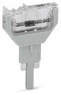
9 Conductor sizes: 0. mm² 0 mm² s + f-st ; Push-in conductor sizes: mm² 0 mm² s and. mm² 6 mm² insulated ferrule, 2 mm 2 Conductor sizes: 0. mm² 6 mm² s + f-st ; Push-in conductor sizes: 2. mm² 6 mm² s and 2. mm² 0 mm² insulated ferrule, 8 mm 3 Conductor sizes: 0. mm² 6 mm² s + f-st, 2 mm² f-st ; Push-in conductor sizes: 2. mm² 6 mm² s and 2. mm² 6 mm² insulated ferrule, 8 mm 4 Suitable for Ex e II applications Strip length, see packaging or instructions. Diode module with N4007 diode U N 2 V, U RM 000 V I N A Plug width.2 mm / 0.20 in! Pluggable Diode Modules on Carrier Terminal Blocks 2. (4) mm², 2002 Series Length of : 66. mm / 2.62 in 2-conductor carrier terminal block 2 Length of : 87. mm / 3.4 in 4-conductor carrier terminal block 3 Length of : 72.9 mm / 2.87 in 2-conductor carrier terminal block with additional jumper position 4 See application notes in Full Line Catalog, Volume, for: Colored push-in type jumper bars, page 39 Staggered jumper, page 4 Push-in type wire jumper, page 40 7 Volume Accessories Diode module, with N4007 diode, max. operating temperature: 8 C,.2 mm wide gray / Carrier Term. Blocks and Accessories Appropriate marking system: WMB/Marking strips 2-conductor carrier terminal block, (4) mm² / AWG 22-2 Terminal block width.2 mm / 0.20 in gray End and intermediate plate, mm thick orange gray conductor carrier terminal block, (4) mm² / AWG 22-2 Terminal block width.2 mm / 0.20 in gray End and intermediate plate, mm thick orange gray Push-in type wire jumper, 4 insulated, I N 6 A, wire size. mm² L = 60 mm (0x0) L = 0 mm (0x0) L = 2 mm (0x0) Push-in type jumper bar, insulated, 4 I N 2 A, light gray 2-way way way way way way way way way Push-in type jumper bar, insulated, I N 2 A, light gray from to from to from to from to from to from to from to from to conductor carrier terminal block, (4) mm² / AWG 22-2 Terminal block width.2 mm / 0.20 in gray End and intermediate plate, mm thick orange gray Insulation stop, pcs/strip, mm² light gray Insulation stop, pcs/strip, mm² dark gray Staggered jumper, 4 insulated, I N 2 A, light gray 2-way 3-way 4-way -way 6-way 7-way 8-way 9-way 0-way -way 2-way (2x2) (2x2) (2x2) (2x2) (2x2) (2x2) (2x2) (2x2)
 mm² 2003 Series 0.2-2. (4) mm² AWG 22-2 2 V/4 kv/3; 20 A (2 A) 2 3 400 V/6 kv/3; 20 A (2 A) 2 4 Terminal block width.2 mm / 0.")

 Multilevel installation terminal block, gray L/L 2003-6642 N/L 2003-6649 Multilevel installation terminal block, gray N/L/PE 2003-6646 L/L/PE 2003-664 Test plug adapter N,")
10 8 44,3 mm/.74 in 44,3 mm/.74 in 6,7 mm/2.32 in 0 mm/4.33 in 6,7 mm/2.32 in 0 mm/4.33 in 6,7 mm/2.32 in 0 mm/4.33 in 44,3 mm/.74 in 44,3 mm/.74 in 6,7 mm/2.32 in 44,3 mm/.74 in Volume Multilevel Installation Terminal Blocks 2. (4) mm² 2003 Series (4) mm² AWG V/4 kv/3; 20 A (2 A) V/6 kv/3; 20 A (2 A) 2 4 Terminal block width.2 mm / 0.20 in L 0-2 mm / 0.43 in (4) mm² AWG V/6 kv/3 2 I N 24 A (28 A) Terminal block width.2 mm / 0.20 in L 0-2 mm / 0.43 in (4) mm² AWG V/4 kv/3; 24 A (28 A) V/6 kv/3; 24 A (28 A) 2 4 Terminal block width.2 mm / 0.20 in L 0-2 mm / 0.43 in Multilevel installation terminal block, with movable knife disconnect, gray NT/L/PE LT/L/PE Item-Specific Accessories Test plug adapter N/L, for vertical test slot, gray 2-pole (4x2) Multilevel installation terminal block, gray L/L N/L Multilevel installation terminal block, gray N/L/PE L/L/PE Test plug adapter N, for vertical test slot, gray -pole (4x2) 6,7 mm/2.32 in 0 mm/4.33 in 6,7 mm/2.32 in 0 mm/4.33 in Multilevel installation terminal block, carrier terminal block without knife disconnect, gray Maximum current depends on accessories used. Multilevel installation terminal block, gray N/L/PE L N Black upper-deck, brown middle-deck, green-yellow lower-deck printing Item-Specific Accessories Test plug adapter N/L, for vertical test slot, gray 2-pole (4x2) Test plug adapter N, for vertical test slot, gray -pole (4x2)
 with N/L test plug adapter (2003-499) for insulation resistance measurement with connected N and L potentials Multilevel installation")

11 Accessories for Multilevel Installation Terminal Blocks! 9 Volume Multilevel installation terminal block ( ) with N/L test plug adapter ( ) for insulation resistance measurement with connected N and L potentials Multilevel installation terminal block ( ) with N test plug adapter (2003-0) for insulation resistance measurement of N potential Conductor sizes: 0.2 mm² 4 mm² s + f-st ; Push-in conductor sizes: 0.7 mm² 4 mm² s and 0.7 mm² 2. mm² insulated ferrules, 2 mm 2 2 V/ 400 V = rated voltage 4 kv/ 6 kv = rated surge voltage 3 = pollution degree (see Full Line Catalog, Volume, Section 4) 3 2 V/4 kv potential-ground V/6 kv potential-potential Strip length, see packaging or instructions. Accessories Multilevel Installation Terminal Block Push-in type jumper bars and staggered jumpers, see 2002 Series End and intermediate plate, Insulation stop, 0.8 mm thick pcs/strip, orange mm² light gray Adjacent jumper for continuous commoning, insulated, Insulation stop, I N 2 A, light gray pcs/strip, mm² 2-way dark gray Busbar carrier, Staggered jumper, not suitable as end stop, for DIN 3 rail,. mm thick insulated, I N 2 A, light gray blue way way Busbar carrier, 4-way can replace end bracket, with detachable -way (2x2) separator plate, 6-way (2x2) for DIN 3 rail, 2 7-way (2x2) 7. mm thick 8-way (2x2) blue way (2x2) Push-in type jumper bar, insulated, 0-way (2x2) I N 2 A, -way (2x2) light gray 2-way (2x2) 2-way way Push-in type wire jumper, 4-way insulated, -way I N 6 A, 6-way wire size. mm² 7-way L = 60 mm (0x0) 8-way L = 0 mm (0x0) 9-way L = 2 mm (0x0) 0-way Push-in type jumper bar, insulated, I N 2 A, light gray WMB Multi marking system, 0 strips with 0 markers per card, stretchable -.2 mm from to plain 793- from to WMB Inline, plain, from to stretchable -.2 mm, from to ,0 WMB markers, mm, on roll from to white from to Marking strip, plain, from to mm wide, from to m roll Operating tool, 3. mm and 2. mm blade, for TOPJOB S installation terminal blocks white Operating tool, 3. mm and. mm blade, for TOPJOB S installation terminal blocks Multilevel installation terminal block ( ) with N/L test plug adapter ( ) for insulation resistance measurement with connected N and L potentials Multilevel installation terminal block ( ) with N test plug adapter (2003-0) for insulation resistance measurement of N potential
 mm² AWG 22-2 0 V/6 kv/3 2 I N 24 A (28 A) Terminal block width.2 mm / 0.20 in L 0-2 mm / 0.")


12 0,7 mm/2.04 in,7 mm/2.04 in,7 mm/2.04 in 93 mm/3.66 in 93 mm/3.66 in 93 mm/3.66 in,7 mm/2.04 in,7 mm/2.04 in,7 mm/2.04 in Volume Double-Deck Terminal Blocks 2. (4) mm² 2002 Series (4) mm² AWG V/6 kv/3 2 I N 24 A (28 A) Terminal block width.2 mm / 0.20 in L 0-2 mm / 0.43 in (4) mm² AWG V/6 kv/3 2 I N 24 A (28 A) Terminal block width.2 mm / 0.20 in L 0-2 mm / 0.43 in (4) mm² AWG V/6 kv/3 2 I N 24 A (28 A) Terminal block width.2 mm / 0.20 in L 0-2 mm / 0.43 in 3 Through/through terminal block, same profile as double-deck disconnect terminal block without marker carrier, gray housing L/L N/L L/N Other terminal blocks with the same profile: Carrier Page 8 Disconnect Page 8 Through/through terminal block, same profile as double-deck disconnect terminal block without marker carrier, blue housing N/N Ground conductor/through terminal block, same profile as double-deck disconnect terminal block without marker carrier, gray housing PE/N PE/L mm/3.66 in 93 mm/3.66 in 93 mm/3.66 in 4-conductor through terminal block, 4-conductor through terminal block, same profile as double-deck disconnect terminal block, without marker carrier, internal commoning, conductor entry position colored in violet, gray housing same profile as double-deck disconnect terminal block, without marker carrier, internal commoning, conductor entry position colored in violet, blue housing L N Through/through terminal block, same profile as double-deck disconnect terminal block without marker carrier, internal commoning, green-yellow housing PE
13 ! Volume Conductor sizes: 0.2 mm² 4 mm² s + f-st ; Push-in conductor sizes: 0.7 mm² 4 mm² s and 0.7 mm² 2. mm² insulated ferrule, 2 mm 2 0 V = rated voltage 6 kv = rated surge voltage 3 = pollution degree (see Full Line Catalog, Volume, Section 4) 3 Strip length, see packaging or instructions. 4 Suitable for Ex i applications noch klären See application notes in Full Line Catalog, Volume, for: Colored push-in type jumper bars, page 39 Vertical jumper, page Series Accessories Appropriate marking systems: WMB/Marking strips/wmb Inline End and intermediate plate, mm thick orange gray Double-deck marker carrier, pivoting gray (2x2) Insulation stop, pcs/strip, mm² light gray Insulation stop, pcs/strip, mm² dark gray Push-in type jumper bar, insulated, I N 2 A, light gray 2-way way way way way way way way way Push-in type jumper bar, insulated, I N 2 A, light gray from to from to from to from to from to from to from to from to Double-deck vertical jumper, insulated, I N 24 A light gray
 mm² AWG 22-2 400 V/6 kv/3 2 I N 6 A Terminal block width.2 mm / 0.20 in L 0-2 mm / 0.43 in 3! Conductor sizes: 0.")

14 2 Volume Double-Deck Disconnect Terminal Blocks and Carrier Terminal Blocks 2. (4) mm², 2002 Series (4) mm² AWG V/6 kv/3 2 I N 6 A Terminal block width.2 mm / 0.20 in L 0-2 mm / 0.43 in (4) mm² AWG V/6 kv/3 2 I N 6 A Terminal block width.2 mm / 0.20 in L 0-2 mm / 0.43 in 3! Conductor sizes: 0.2 mm² 4 mm² s + f-st ; Push-in conductor sizes: 0.7 mm² 4 mm² s and 0.7 mm² 2. mm² insulated ferrule, 2 mm 93 mm/3.66 in,7 mm/2.04 in 6,4 mm/2.22 in 93 mm/3.66 in,7 mm/2.04 in 2 0 V = rated voltage 6 kv = rated surge voltage 3 = pollution degree (see Full Line Catalog, Volume, Section 4) 3 Strip length, see packaging or instructions. 4 See application notes in Full Line Catalog, Volume, for: Colored push-in type jumper bars, page 39 Vertical jumper, page 42 Double-deck disconnect terminal block, with movable knife disconnect, gray housing L/L N/L Double-deck carrier terminal block, upper deck carrier, gray housing L/L N/L Series Accessories Appropriate marking systems: WMB/Marking strips/wmb Inline End and intermediate plate, mm thick orange gray Double-deck marker carrier, pivoting gray (2x2) 93 mm/3.66 in,7 mm/2.04 in Double-deck carrier terminal block, upper deck carrier, gray housing PE/L Insulation stop, pcs/strip, mm² light gray Insulation stop, pcs/strip, mm² dark gray Push-in type jumper bar, insulated, 4 I N 2 A, light gray 2-way way way way way way way way way Push-in type jumper bar, insulated, I N 2 A, light gray from to from to from to from to from to from to from to from to Double-deck vertical jumper, insulated, 4 I N 24 A light gray
 mm², 2002 Series 3 Volume 93 mm/3.66 in 76,4 mm/3.0 in 93 mm/3.66 in 76,4 mm/3.0 in Conductor sizes: 0.2 mm² 4 mm² s + f-st ; Push-in conductor sizes: 0.7 mm² 4 mm² s and 0.7 mm² 2.")

15 (4) mm² AWG V/6 kv/3 2 I N 6 A Terminal block width 6.2 mm / in L 0-2 mm / 0.43 in (4) mm² AWG V/6 kv/3 2 I N 6 A Terminal block width 6.2 mm / in L 0-2 mm / 0.43 in 3! Double-Deck Fuse Disconnect Terminal Blocks with Pivoting Fuse Holder 2. (4) mm², 2002 Series 3 Volume 93 mm/3.66 in 76,4 mm/3.0 in 93 mm/3.66 in 76,4 mm/3.0 in Conductor sizes: 0.2 mm² 4 mm² s + f-st ; Push-in conductor sizes: 0.7 mm² 4 mm² s and 0.7 mm² 2. mm² insulated ferrule, 2 mm V = rated voltage 6 kv = rated surge voltage 3 = pollution degree (see Full Line Catalog, Volume, Section 4) 3 Strip length, see packaging or instructions. See application notes in Full Line Catalog, Volume, for: Vertical jumper, page 42 Double-deck fuse disconnect terminal block with pivoting fuse holder, Through/fuse terminal block, for miniature metric fuses x 20 mm, without blown fuse indication Nominal voltage and current are given by the fuse. Double-deck fuse disconnect terminal block with pivoting fuse holder, Through/fuse terminal block, for miniature metric fuses x 20 mm, with blown fuse indication by LED, gray Nominal voltage and current are given by the LED or fuse. Leakage current in case of blown fuse: LED 2mA L/L N/L V / V / V / Protective warning marker and insulation stop must be applied individually. Due to the 6.2 mm/0.244 in width of the fuse terminal blocks with pivoting fuse holder, 2004 Series jumpers must be used Series Accessories Appropriate marking systems: WMB/Marking strips (see Full Line Catalog, Volume, Section 3) End and intermediate plate, mm thick orange gray Push-in type jumper bar, insulated, I N 32 A, light gray 2-way 3-way 4-way -way 6-way 7-way 8-way 9-way 0-way Push-in type jumper bar, insulated, 4 I N 32 A, light gray from to 3 from to 4 from to from to 6 from to 7 from to 8 from to 9 from to End plate for fuse terminal blocks, 2 mm thick orange gray Insulation stop, pcs/strip, mm² light gray Insulation stop, pcs/strip, mm² dark gray Protective warning marker, with high-voltage symbol, black, for terminal blocks yellow Marking strip, plain, mm wide, m roll white Pivoting the fuse holder in the locked open position. Double-deck vertical jumper, insulated, 4 I N 24 A light gray Fuse replacement
 mm² AWG 20-8 0 V/6 kv/3 2 I N 30 A Terminal block width 8 mm / 0.3 in L 3 - mm / 0. in 3 0. - 6 (0) mm² AWG 20-8 0 V/6 kv/3 2 I N 30 A Terminal block width 8 mm / 0.3 in L 3 - mm / 0. in 3 0. - 6 (0) mm² AWG 20-8 0 V/6 kv/3 2 I N 30 A Terminal block width 8 mm / 0.3 in L 3 - mm / 0. in 3 99,6 mm/3.")
16 4 6,3 mm/2.7 in Volume 6,3 mm/2.7 in 46,8 mm/.8 in Disconnect Terminal Blocks for Test and Measurement, 6 mm²/30 A, for Current and Voltage Transformer Circuits, 2006 Series (0) mm² AWG V/6 kv/3 2 I N 30 A Terminal block width 8 mm / 0.3 in L 3 - mm / 0. in (0) mm² AWG V/6 kv/3 2 I N 30 A Terminal block width 8 mm / 0.3 in L 3 - mm / 0. in (0) mm² AWG V/6 kv/3 2 I N 30 A Terminal block width 8 mm / 0.3 in L 3 - mm / 0. in 3 99,6 mm/3.92 in 99,6 mm/3.92 in 99,6 mm/3.93 in 2-conductor disconnect terminal block for test and measurement, e.g., current and voltage transformer circuits, with touch-proof test sockets, for 4 mm Ø test plug gray conductor disconnect terminal block, with touch-proof test sockets, for 4 mm Ø test plug gray conductor through terminal block, with touch-proof test sockets, for 4 mm Ø test plug gray Series Accessories End and separator plate,. mm thick, without use of lock-out seal Adjacent jumper for switch lever, insulated, orange, I N 30 A orange (x0) 2-way gray (x0) 3-way End and separator plate,. mm thick, 4-way for use of lock-out seal -way orange (x0) 6-way gray (x0) 7-way Lock-out, 8-way for disconnect link yellow (x20) Locking cover, transparent, mechanically locks multiple links -pole (x0) 2-pole (x0) 3-pole (x0) 4-pole (x0) -pole (x0) 6-pole (x0) 7-pole (x0) 8-pole (x0) Interlocking link, mechanically locks multiple links, m/3 3 long transparent Protective warning marker, with high-voltage symbol, black, for terminal blocks yellow Appropriate marking systems: WMB/Marking strips (see Full Line Catalog, Volume, Section 3) Jumper, insulated, I N 30 A, orange 2-way way way way way way way way way Jumper with safety lid, insulated, I N 30 A, orange 2-way 3-way 4-way Jumper, special design, I N 30 A, orange (x0) (x0) (x0) (x0) (x0) (x0) (x0) (x0) (x0) (x0) (x0) (x0) (x0) (x0) (x0) (x0) / / / (x0) / /0-000 (x0) WMB Multi marking system, 0 strips with 0 markers per card, for terminal widths - 7. mm plain 793- WMB Multi marking system, plain, 0 strips with 0 markers per card, for terminal widths - 7. mm yellow 793-/ red 793-/ blue 793-/ gray 793-/ orange 793-/ light green 793-/ green 793-/ violet 793-/ WMB Multi marking system, 0 strips with 0 markers per card, for terminal widths - 7. mm, yellow k/l (x) 794-3/ WMB Multi marking system, 0 strips with 0 markers per card, for terminal widths - 7. mm, blue U/V (x) 794-4/ Marking strip, plain, mm wide, m roll white


 3 Strip")


17 ! (0) mm² AWG 20-8 Terminal block width 8 mm / 0.3 in L 3 - mm / 0. in Volume 99,6 mm/3.93 in 46,8 mm/.8 in Integrated test sockets for touchproof 4 mm Ø test plugs. Conductor sizes: 0. mm² 0 mm² s + f-st ; Push-in conductor sizes: mm² 0 mm² s and. mm² 6 mm² insulated ferrule, 2 mm 2 0 V = rated voltage 6 kv = rated surge voltage 3 = pollution degree (see Full Line Catalog, Volume, Section 4) 3 Strip length, see packaging or instructions. 2-conductor ground terminal block, with touch-proof test sockets, for 4 mm Ø test plug green-yellow Lock-out prevents accidental operation of disconnect link. Lock-out has snap action into two notched positions. Marking via WMB Multi markers or marking strips. Multipole switching via snap-on type, transparent (locking) cover for disconnect links.
 mm² AWG 20-8 AC/DC 000 V/ DC 0 V/2 kv/3 2 I N 30 A Terminal block width mm / 0.9 in L 3 - mm / 0. in 3 0.")

18 6 Volume Disconnect Terminal Blocks for Test and Measurement 0 VDC, Carrier/ Through Terminal Blocks of Same Profile 6 (0) mm²/30 A, 2006 Series (0) mm² AWG 20-8 AC/DC 000 V/ DC 0 V/2 kv/3 2 I N 30 A Terminal block width mm / 0.9 in L 3 - mm / 0. in (0) mm² AWG 20-8 AC/DC 000 V/ DC 0 V/2 kv/3 2 I N 30 A Terminal block width mm / 0.9 in L 3 - mm / 0. in (0) mm² AWG 20-8 AC/DC 000 V/ DC 0 V/2 kv/3 2 I N 30 A Terminal block width mm / 0.9 in L 3 - mm / 0. in 3 9,2 mm/2.33 in 33 mm/.3 in 33 mm/.3 in 06,9 mm/4.2 in 06,9 mm/4.2 in 06,9 mm/4.2 in 2-conductor disconnect terminal block for test and measurement, with test point, orange disconnect link gray blue Series Accessories End and intermediate plate, mm thick orange gray Protective warning marker, with high-voltage symbol, black, for terminal blocks yellow Push-in type jumper bar, insulated, I N 4 A, light gray from to from to Lockout cap, (2x2) (2x2) gray blue Appropriate marking systems: WMB/Marking strips (see Full Line Catalog, Volume, Section 3) WMB Multi marking system, 0 strips with 0 markers per card, for terminal widths - 7. mm plain 793- WMB Multi marking system, plain, 0 strips with 0 markers per card, for terminal widths - 7. mm yellow red blue gray orange light green green violet 2-conductor carrier terminal block, with test point Marking strip, plain, for conductor entry hole and operating mm wide, slot m roll gray white / / / / / / / / conductor through terminal block, with test point, same profile as 2-conductor disconnect terminal block gray blue WMB Multi marking system, 0 strips with 0 markers per card, stretchable -.2 mm plain 793- WMB Multi marking system, plain, 0 strips with 0 markers per card, stretchable -.2 mm yellow red blue gray orange light green green violet 793-/ / / / / / / / WMB Inline, plain, stretchable -.2 mm,,0 WMB markers, mm, on roll white 2009-


 Carrier terminal block with")
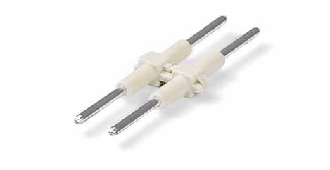
19 ! Disconnect plug for carrier terminal blocks 0 V/2 kv/3 I N 30 A 7 Volume Protective warning marker must be applied individually. Conductor sizes: 0. mm² 0 mm² s + f-st ; Push-in conductor sizes: mm² 0 mm² s and. mm² 6 mm² insulated ferrule, 2 mm 2 AC/DC 000 V = rated voltage DC 000 V 2 kv = rated surge voltage 3 = pollution degree (see Full Line Catalog, Volume, Section 4) 3 Strip length, see packaging or instructions. Disconnect plug for carrier terminal blocks, suited when using a carrier terminal block as disconnect terminal block orange (4x2) Carrier terminal block with disconnect plug in parked position. Carrier terminal block with disconnect plug in operating position.


 2 Electrical ratings are given by the fuse (see Full Line Catalog, Volume, pages")


 can be")
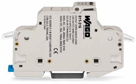
20 3 8 Volume Fuse Terminal Blocks for Cylindrical Fuses 0 x 38 mm²; 3/32 x -/2 8 Series mm² AWG V/8 kv/3 2 I N 32 A Terminal block width 7 mm / in L 2-3 mm / 0.49 in 3 " Available: January 203 < 0 mm/4.3 in > < mm/2.6 in > Conductor termination: Open clamping unit via integrated lever. 400 V = rated voltage 6 kv = rated surge voltage 3 = pollution degree (see Full Line Catalog, Volume, Section 4) 2 Electrical ratings are given by the fuse (see Full Line Catalog, Volume, pages ). 3 Strip length, see packaging or instructions. Fuse terminal block for cylindrical fuses 0 x 38 mm; 3/32 x /2, without blown fuse indication, suitable for DIN 3 rail acc. to EN 607 Nominal voltage and current are given by the LED or fuse. light gray Fuse terminal block for cylindrical fuses 0 x 38 mm; 3/32 x /2, with blown fuse indication, V DC, suitable for DIN 3 rail acc. to EN 607 Nominal voltage and current are given by the LED or fuse. light gray Cylindrical fuses are not offered by WAGO. Temperature scale handling from - C to +8 C Ferruled conductors up to 0 mm² (AWG 8) can be terminated. Inserting a fuse. Remove terminal block from the carrier rail.
 and 3 mm² (28/78 Series) gray 283-407 2 Always push voltage tap down into the terminal block until fully")
21 Voltage Tap 283 Series V/8 kv/3 I N 24 A Volume 800 V = rated voltage 8 kv = rated surge voltage 3 = pollution degree (see Full Line Catalog, Volume, Section 4) Voltage tap, with 0 mm cable, for terminal blocks 6 mm² (283/783 Series) and 3 mm² (28/78 Series) gray Always push voltage tap down into the terminal block until fully inserted!
 2 See")
22 7 20 Volume X-COM -SYSTEM Male Headers with Solder Pins and Rivet Fixing Flanges Pin Spacing mm Pin spacing mm / 0.97 in, gray 2 V/4 kv/3 300 V, 20 AU 0 V/4 kv/2 300 V, 20 A2 I N 32 A 2 2 V/0 V = rated voltage 4 kv = rated surge voltage 3/2 = pollution degree (see Full Line Catalog, Volume, Section 4) 2 See current-carrying capacity curve, page 378 and at Pole No. Male header with straight solder pins and rivet fixing flanges, x mm, gray / / / / / / / / / / / / / / Mounting with 3 mm Ø blind rivets Accessories -conductor female plug, Pole straight gray Coding pin, for coding female plugs orange conductor female plug, Pole with lateral locking levers gray / ,2 22,2 L L2 L3 3,6 2,6 2,6 9,7 6, 3 9,9 6,7 3, 6,9 8,3 7,8,4 8,7 3,7, 2,8,2 L L = L mm, L2 = L + 7 mm, L3 = L + 3. mm L = (No. of poles - ) x pin spacing mm Dimensions in mm

23 Orange Version! 7 2 Technical Data see Full Line Catalog, Volume -Conductor/-Pin Carrier Terminal Blocks Page Conductor/-Pin-Carrier Terminal Blocks Page Conductor/2-Pin-Carrier Terminal Blocks Page 396 and Female Plugs for Self-Assembly Page 402 -conductor end module conductor center module conductor base module and -Conductor Female Plugs Page / / / / / / / / / / / / / / / Volume
 mm² AWG 24-6 0 V/6 kv/3 2 I N 3. A 3 module width 3. mm / 0.38 in L 9 - mm / 0.39 in 4 0.4 - (.) mm² AWG 24-6 0 V/6 kv/3 2 I N 3. A 3 module width 3. mm / 0.38 in L 9 - mm / 0.39 in 4 Pole Pole Pole Pole Pole Pole Pole No.")
, for insertion into carrier terminal blocks, with coding fingers 3 2020-03/000-037 Pole No.")
24 7 22 Volume Pre-Assembled Female Plugs 2020 Series (.) mm² AWG V/6 kv/3 2 I N 3. A 3 module width 3. mm / 0.38 in L 9 - mm / 0.39 in (.) mm² AWG V/6 kv/3 2 I N 3. A 3 module width 3. mm / 0.38 in L 9 - mm / 0.39 in (.) mm² AWG V/6 kv/3 2 I N 3. A 3 module width 3. mm / 0.38 in L 9 - mm / 0.39 in 4 Pole Pole Pole Pole Pole Pole Pole No. -conductor female plug with ground base module (green-yellow), for insertion into carrier terminal blocks, with coding fingers / conductor female plug with ground end module (green-yellow), for insertion into carrier terminal blocks, with coding fingers / Pole No. -conductor female plug with ground base module (green-yellow), for insertion into carrier terminal blocks, with coding fingers / conductor female plug with ground end module (green-yellow), for insertion into carrier terminal blocks, with coding fingers / Pole No. -conductor female plug with ground base module (green-yellow), for insertion into carrier terminal blocks, with coding fingers / conductor female plug with ground end module (green-yellow), for insertion into carrier terminal blocks, with coding fingers / For other lengths up to maximum poles, please contact factory. Accessories Female Plugs Protective warning marker, with high-voltage symbol, black, for terminal blocks yellow Locking lever, 9.6 mm wide orange gray Locking lever, 4.8 mm wide orange gray Strain relief plate, gray 3 mm width mm wide mm width mm wide For other lengths up to maximum poles, please contact factory. Appropriate marking systems: WMB/Marking strips (see Full Line Catalog, Volume, Section 3) For other lengths up to maximum poles, please contact factory. WMB Multi marking system, 0 strips with 0 markers per card, for 3. mm terminal block width plain Marking strip, plain, mm wide, m roll white
25 ! (.) mm² AWG V/6 kv/3 2 I N 3. A 3 module width 3. mm / 0.38 in L 9 - mm / 0.39 in 4 23 Volume Pole Pole Conductor sizes: 0.4 mm². mm² s + f-st ; Push-in conductor sizes: 0. mm². mm² s and 0. mm² 0.7 mm² insulated ferrule, 0 mm 2 0 V = rated voltage 6 kv = rated surge voltage 3 = pollution degree (see Full Line Catalog, Volume, Section 4) 3 Current-carrying capacity curves upon request 4 Strip length, see packaging or instructions. Pole No. -conductor female plug with ground base module (green-yellow), for insertion into carrier terminal blocks, with coding fingers / conductor female plug with ground end module (green-yellow), for insertion into carrier terminal blocks, with coding fingers / For other lengths up to maximum poles, please contact factory.

26 2 24 Volume Vario-T-BOXX and Variobox Vario-T-BOXX High-quality Sortimo plastic case containing a selection of WAGO installation connectors Dimensions: 440 x 3 x 80 mm Variobox Indestructible Sortimo metal case containing a selection of WAGO installation connectors Dimensions: 440 x 330 x 66 mm Description Vario-T-BOXX, Variobox Vario-T-BOXX Variobox High-quality Sortimo cases contain a selection of WAGO connectors for all applications in electrical building installations. Contains: COMPACT PUSH WIRE connectors for junction boxes 2 x mm x mm x mm x mm Contains: COMPACT PUSH WIRE connectors for junction boxes 2 x mm x mm x mm x mm Compact splicing connectors 3 x mm x mm Compact splicing connectors 3 x mm x mm Lighting connectors - 2. mm Lighting connectors - 2. mm MICRO PUSH WIRE connectors for junction boxes dark gray 4 x mm Ø red 4 x mm Ø dark gray 8 x mm Ø Mounting carrier for 6 connectors MICRO PUSH WIRE connectors for junction boxes dark gray 4 x mm Ø red 4 x mm Ø dark gray 8 x mm Ø Mounting carrier for 6 connectors
27 2 2 Volume


28 26 Volume 2

29 Contents Volume 2 Series Pages SMD Terminal Blocks with Push-Buttons Pin Spacing 4 mm, Black SMD Terminal Blocks with Push-Buttons Pin Spacing 8 mm Volume 2 Connecting Link for SMD Terminal Blocks with Push-Buttons, Pin Spacing 4 mm THR Terminal Strips with Push-Buttons Pin Spacing 3. mm PCB Terminal Strips with Push-Buttons Pin Spacing 3. mm PCB Terminal Strips with Push-Buttons Pin Spacing 2. mm Modular PCB Terminal Blocks and Strips with Angled Push-Buttons Pin Spacing: /.08 mm, 7./7.62 mm, 0/0.6 mm
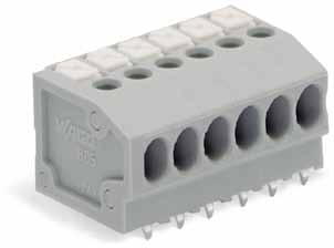
30 28 Volume 2 SMD Terminal Blocks with Push-Buttons, 0.7 mm 2 Pin Spacing 4 mm, Black 2060 Series SMD terminal blocks with CAGE CLAMP S and push-buttons Push-in termination of rigid, solid conductors and fine-stranded conductors with ferrules Convenient termination/removal of fine-stranded conductors via pushbuttons Just 4. mm high Available in tape-and-reel packaging for automated assembly For light gray versions, see Full Line Catalog, Volume 2, page 8. Technical data: Pin Spacing 4 mm 0.7 in Ratings per IEC/EN Overvoltage category III III II Pollution degree Rated voltage 63 V 60 V 320 V Rated surge voltage 2. kv 2. kv 2. kv Nominal current 9 A 9 A 9 A Approvals per UL 977 Rated voltage, -pole 600 V Rated voltage, 2 or more poles 2 V Nominal current UL 9 A Conductor data: Connection technology CAGE CLAMP S Conductor size: solid mm 2 Conductor size: fine-stranded mm 2 Conductor size: fine-stranded mm 2 (with insulated ferrule) Conductor size: fine-stranded mm 2 (with uninsulated ferrule) AWG 24 8 Strip length 6 7 mm / in Conductor entry angle 0 to PCB Material data: Material group I Insulating material Glass-fiber-reinforced polyphthalamide (PPA-GF) Flammability rating per UL 94 0V Lower/Upper limit temperature 60 C / +0 C Contact material Copper alloy Contact plating Tin-plated Current-Carrying Capacity Curve Pin spacing: 4 mm / Conductor size: 0.7 mm 2 f-st Based on: EN / Reduction factor: Current in A , 4-, 6-pole Accessories for 2060 Series: Ambient operating temperature in C Conductor rated current Volume 2/Page: Operating tool (233-33) 27 Application note: Suitable for lead-free, reflow-soldering profiles acc. to DIN EN and IEC up to max. 260 C peak temperature. Due to customer specific variables (e.g., component configuration and orientation, type of soldering machine, solder paste), it is recommended that trial runs are conducted to ensure product and process compatibility under actual manufacturing conditions. Recommendation for SMD positioning pattern: Material thickness, µm. Pattern layout identical to solder pad layout. Approvals are available online at: For more technical information, see Full Line Catalog, Volume 2, Section

 > < 0,9 ( 4 ) < 4 2 < > > 0,4 > < 0,4 > < < A > > 0,4 < < 24 > <, > L =")

 + 4 mm Terminal blocks can be arranged side by side without loss of poles.")
31 SMD Terminal Blocks with Push-Buttons, 0.7 mm 2! 29 Pin spacing 4 mm / 0.7 in mm 2 AWG V/2. kv/2 9 A Volume 2 4 < > < 3, > <,7 > < 0, > < 4, > < L > < 4 > 2,2 < > R >< 0,3 >,3 <,4 <_ 6, _> > < < 4 > > < 2, <_ 6 _> > 3, <,2 < ) > < 0,9 ( 4 ) < 4 2 < > > 0,4 > < 0,4 > < < A > > 0,4 < < 24 > <, > L = (pole no. x pin spacing) 0. mm / Pole No. Pieces per Reel SMD terminal blocks with push-buttons in tape-and-reel packaging, black / / / R = Feed direction A = (No. of poles x pin spacing) + 4 mm Terminal blocks can be arranged side by side without loss of poles. Reel diameter: 330 mm Inserting solid conductors via push-in termination. Insert/remove fine-stranded conductors by lightly pressing on push-button (e.g., using a operating tool or a ball point pen)

32 30 Volume 2 SMD Terminal Blocks with Push-Buttons, 0.7 mm 2 Pin Spacing 8 mm 2060 Series SMD terminal blocks with CAGE CLAMP S and push-buttons 8 mm pin spacing version for higher rated voltages Push-in termination of rigid, solid conductors and fine-stranded conductors with ferrules Convenient termination/removal of fine-stranded conductors via pushbuttons Height of just 4. mm minimizes on-board LED shadowing Available in tape-and-reel packaging for automated assembly Technical data: Pin Spacing 8 mm 0.34 in Ratings per IEC/EN Overvoltage category III III II Pollution degree Rated voltage 400 V 630 V 000V Rated surge voltage 6 kv 6 kv 6 kv Nominal current 9 A 9 A 9 A Approvals per UL 977 Rated voltage 600 V Nominal current UL 9 A Current-Carrying Capacity Curve Pin spacing: 4 mm / Conductor size: 0.7 mm 2 f-st Based on: EN / Reduction factor: Current in A 20 0 Conductor data: Connection technology CAGE CLAMP S Conductor size: solid mm 2 Conductor size: fine-stranded mm 2 Conductor size: fine-stranded mm 2 (with insulated ferrule) Conductor size: fine-stranded mm 2 (with uninsulated ferrule) AWG 24 8 Strip length 6 7 mm / in Conductor entry angle 0 to PCB Material data: Material group I Insulating material Glass-fiber-reinforced polyphthalamide (PPA-GF) Flammability rating per UL 94 0V Lower/Upper limit temperature 60 C / +0 C Contact material Copper alloy Contact plating Tin-plated Ambient operating temperature in C 2-, 4-, 6-pole Conductor rated current Accessories for 2060 Series: Volume 2/Page: Operating tool (233-33) 27 Application note: Suitable for lead-free, reflow-soldering profiles acc. to DIN EN and IEC up to max. 260 C peak temperature. Due to customer specific variables (e.g., component configuration and orientation, type of soldering machine, solder paste), it is recommended that trial runs are conducted to ensure product and process compatibility under actual manufacturing conditions. Recommendation for SMD positioning pattern: Material thickness, µm. Pattern layout identical to solder pad layout. Approvals are available online at: For more technical information, see Full Line Catalog, Volume 2, Section
 > < 0,9 < ( 4 ) L = (pole no. x pin spacing) 0.")

33 SMD Terminal Blocks with Push-Buttons, 0.7 mm 2! 3 Pin spacing 8 mm / 0/34 in mm 2 AWG V/6 kv/2 9 A Volume 2 4 < < 3, > <,7 > < < 8 > 0, >,4 <_ 6, _> > < < 4 > > < 2, <_ 6 _> > 3, < > < 4, >,2 < ) > < 0,9 < ( 4 ) L = (pole no. x pin spacing) 0. mm L < 4 2 < > > > 2,2 < > 0,4 > < 0,4 > < R < A > R = Feed direction A = (No. of poles x pin spacing) + 4 mm >< 0,3 > 0,4 < >,3 < < 24 > <, > / Pole No. Pieces per Reel SMD terminal blocks with push-buttons in tape-andreel packaging, light gray* / Reel diameter: 330 mm Inserting solid conductors via push-in termination. (Picture shows 2060 Series) Insert/remove fine-stranded conductors by lightly pressing on push-button (e.g., using a operating tool or a ball point pen) *Depending on reflow soldering temperatures and times, color deviations may occur for light gray connectors. These deviations will have no impact on functionality.

34 32 Volume 2 Connecting Links for SMD Terminal Blocks with Push-Buttons, 0.7 mm 2 Pin Spacing 4 mm 2060 Series Connecting link simplifies LED circuit board assembly Easy push-in termination and disconnection without push-button actuation Technical data: Pin Spacing 4 mm 0.7 in Ratings per IEC/EN Overvoltage category III III II Pollution degree Rated voltage 63 V 60 V 320 V Rated surge voltage 2. kv 2. kv 2. kv Nominal current 9 A 9 A 9 A Approvals per UL/CSA* Rated voltage, -pole Rated voltage, 2 or more poles Nominal current UL Material data: Material group I Insulating material Polyamide 6.6 (PA 6.6) Flammability rating per UL 94 0V Lower/Upper limit temperature 60 C / +0 C Contact material Copper alloy Contact plating Silver-plated Approvals are available online at: For more technical information, see Full Line Catalog, Volume 2, Section *UL/CSA approval pending


35 < < Connecting Links for SMD Terminal Blocks with Push-Buttons, 0.7 mm 2! 33 Pin spacing 4 mm / 0.7 in 60 V/2. kv/2 9 A Volume 2 < 26 > 4 > > < L < <7,2 <, 2,6,9 > < > < < max. 22 > > > > 4, < min. 4,4 max.,4 < < max. 22 > min. 4,4 max.,4 < L = (pole no. x pin spacing) 0.6 mm Pole No. Connecting link for SMD terminal blocks with pushbuttons Inserting the connecting link into terminal block. > > Assembly: Place PCBs on a flat surface and insert links into terminal blocks on adjoining PCBs. Disassembly: Pull PCBs apart. (maximum 0 connections/disconnections) The PCBs must be secured (see figure above).

36 34 Volume 2 THR* Terminal Strips with Push-Buttons,. mm 2 Pin Spacing 3. mm 80 Series Terminal strips with push-button actuated CAGE CLAMP S Simple, push-in terminations of solid and ferruled conductors Push-buttons that close flush with minimal force for convenient termination/removal of fine-stranded conductors Convenient, tool-free operation Technical data: Pin Spacing 3. mm 0.38 in Ratings per IEC/EN Overvoltage category III III II Pollution degree Rated voltage 200 V 320 V 320 V Rated surge voltage 4 kv 4 kv 4 kv Nominal current 7.A 7.A 7.A Approvals per UL/CSA Use group UL 09 B C D Rated voltage Nominal current UL Nominal current CSA Conductor and solder pin data: Connection technology CAGE CLAMP S Conductor size: solid 0.2. mm 2 Conductor size: fine-stranded 0.2. mm 2 Conductor size: fine-stranded 0.2 mm 2 (with insulated ferrule) Conductor size: fine-stranded 0.2 mm 2 (with uninsulated ferrule) AWG 24 6 Strip length 9 0 mm / in Conductor entry angle 0 to PCB Solder pin: length/width 2.2 mm / 0. x 0.7 mm Solder pin: metal-plated hole. +0. mm Ø Material data: Material group III a Insulating material Nylon 4.6 (PA 4.6) Flammability rating per UL 94 V2 Lower/Upper limit temperature 60 C / +0 C Clamping spring material Chrome-nickel spring steel (CrNi) Contact material Electrolytic copper (E Cu ) Contact plating Tin-plated Current-Carrying Capacity Curve Pin spacing: 3. mm / Conductor size:. mm 2 f-st Based on: EN / Reduction factor: Current in A , 4-, 6-, 2-pole Accessories for 80 Series Ambient operating temperature in C Conductor rated current Volume 2/age: Marking accessories Operating tools Test plug 38 Approvals are available online at: For more technical information, see Full Line Catalog, Volume 2, Section *For THR soldering, see Volume 2, page 8
 +. mm Pole No.")
37 THR Terminal Strips with Push-Buttons,. mm 2! 3 Pin spacing 3. mm / 0.38 in 0.2. mm 2 AWG V/4 kv/2 7. A 300 V/0 A Volume 2 < L > < 0,6 < 3,6 > 0,7 > < >2,2< 0,_> > 3, < > 2 < > 0, < 3, > >< <_ < 2,6 > < <_ < 3, < > > < 2 3, > L = (pole no. x pin spacing) +. mm Pole No. THR terminal strip with push-buttons, black / (4 x ) / (4 x 0) / (4 x 7) 80-30/ (4 x 6) / (4 x ) / (4 x 4) / (4 x 40)

38 36 Volume 2 PCB Terminal Strips with Push-Buttons,. mm 2, In-Line Solder Pin/Pole, Front Side, Pin Spacing 3. mm 80 Series Terminal strips with push-button actuated CAGE CLAMP S Version with in-line solder pins Simple, push-in terminations of solid and ferruled conductors Push-buttons that close flush with minimal force for convenient termination/removal of fine-stranded conductors Convenient, tool-free operation Versions with/without test slots and spacers Versions available with custom internal commoning (factory assembly), e.g., commoning ground conductor Technical data: Pin Spacing 3. mm 0.38 in Ratings per IEC/EN Overvoltage category III III II Pollution degree Rated voltage 60 V 60 V 320 V Rated surge voltage 2. kv 2. kv 2. kv Nominal current 7.A 7.A 7.A Approvals per UL/CSA Use group UL 09 B C D Rated voltage Nominal current UL Nominal current CSA Conductor and solder pin data: Connection technology CAGE CLAMP S Conductor size: solid 0.2. mm 2 Conductor size: fine-stranded 0.2. mm 2 Conductor size: fine-stranded 0.2 mm 2 (with insulated ferrule) Conductor size: fine-stranded 0.2 mm 2 (with uninsulated ferrule) AWG 24 6 Strip length 9 0 mm / in Conductor entry angle 0 to PCB Solder pin: length/width 3.2 mm / 0. x 0.7 mm Solder pin: drilled hole diameter. +0. mm Material data: Material group I Insulating material Polyamide 6.6 (PA 6.6) Flammability rating per UL 94 0V Lower/Upper limit temperature 60 C / +0 C Clamping spring material Chrome-nickel spring steel (CrNi) Contact material Electrolytic copper (E Cu ) Contact plating Tin-plated Current-Carrying Capacity Curve Pin spacing: 3. mm / Conductor size:. mm 2 f-st Based on: EN / Reduction factor: Current in A , 4-, 6-, 2-pole Accessories for 80 Series Ambient operating temperature in C Conductor rated current Volume 2/Page: Marking accessories Operating tools Test plug 38 Approvals are available online at: For more technical information, see Full Line Catalog, Volume 2, Section
39 PCB Terminal Strips with Push-Buttons,. mm 2, In-Line Solder Pin/Pole, Front Side! 37 With test slots Pin spacing 3. mm / 0.38 in Pin spacing 3. mm / 0.38 in 0.2. mm 2 AWG mm 2 AWG V/4 kv/2 7. A 300 V/0 A 320 V/4 kv/2 7. A 300 V/0 A Volume 2 < L > < 0,6 < 3,6 > < L > < 0,6 < 3,6 > < 0,_> < 0,_> 0,7 > < > 3, < > 2 < > 0, < <_ < 2,6 > 0,7 > < > 3, < > 2 < > 0, < <_ < 2,6 > L = (pole no. x pin spacing) +. mm Pole No. Pole No. Terminal strip with push-buttons, in-line solder pin/pole, front side, test slots for 2 mm Ø test plug, gray Terminal strip with push-buttons in-line solder pin/pole, front side, gray (4 x ) (4 x ) (4 x 0) (4 x 0) (4 x 80) (4 x 7) (4 x 6) (4 x 6) (4 x ) (4 x ) (4 x 4) (4 x 4) (4 x 40) (4 x 40) (4 x 3) (4 x 3) (4 x 30) (4 x 30) (4 x 2) (4 x 2) (4 x 2) (4 x 2) (4 x 2) (4 x 2) (4 x 2) (4 x 2) (4 x 20) (4 x 20) (4 x 20) (4 x 20) (4 x 20) (4 x 20) (4 x ) (4 x ) (4 x ) (4 x ) (4 x ) (4 x ) (4 x ) (4 x ) (4 x ) (4 x ) (4 x ) (4 x ) (4 x 0) (4 x 0) Item no. suffixes for colored terminal strips (production and prices depend on quantity required): blue... / Ordering example: orange... / Terminal strip, 3. mm pin spacing, 6-pole, blue: 80-36/ For assemblies in other lengths, with in-line solder pins, and other colors or with direct marking, please contact factory.

40 38 Volume 2 PCB Terminal Strips with Push-Buttons, 0. mm 2, In-Line Solder Pin/Pole, Front Side, Pin Spacing 2. mm 2 Series Compact terminal strips with push-buttons Version with in-line solder pins Push-in termination of solid conductors Push-button operation for connecting of fine-stranded conductors and removing of conductors 4 conductor entry angle provides easy, space-saving wiring Custom color combinations Terminal strips also available with spacers upon request Technical data: Pin Spacing 2. mm in Ratings per IEC/EN Overvoltage category III III II Pollution degree Rated voltage 00 V 60 V 320 V Rated surge voltage 2. kv 2. kv 2. kv Nominal current 4 A 4 A 4 A Approvals per UL/CSA Use group UL09 B C D Rated voltage Nominal current UL Nominal current CSA Conductor and solder pin data: Connection technology CAGE CLAMP S Conductor size: solid mm 2 ( mm Ø) Conductor size: fine-stranded mm 2 AWG (26 sol. Strip length mm / in Conductor entry angle 4 to PCB Solder pin: length/width 3.6 mm / 0.4 x 0.7 mm Solder pin: drilled hole diameter mm Current-Carrying Capacity Curve Pin spacing 2. mm / Conductor cross section 0. mm 2 f Based on: EN / Reduction factor Current in A , 4-, 6-, 2-, 24-pole Ambient operating temperature in C Nominal current for terminal strip Material data: Material group I Insulating material Polyamide 6.6 (PA 6.6) Flammability rating per UL 94 0V Lower/Upper limit temperature 60 C / +0 C Clamping spring material Copper alloy Contact plating Copper Accessories for 2 Series Volume 2/Page: Marking accessories Operating tools Test pin 38 Approvals are available online at: For more technical information, see Full Line Catalog, Volume 2, Section
 +. mm Pole No.")
41 PCB Terminal Strips with Push-Buttons, 0. mm 2, In-Line Solder Pin/Pole, Front Side! 39 Pin spacing: 2. mm / in mm 2 AWG V/2. kv/2 4 A Volume 2 < L > 0,4 ( < 7,3 _> < 2 > < > 3,6 <, > < 3, >,3 > 2, < 0,7 > <,2 > < L = (pole no. x pin spacing) +. mm Pole No. Color Terminal strip with push-buttons in-line solder pin/pole, front side, gray Additional item nos. for colored terminal strips: (4 x 80) black / (4 x 30) red / (4 x 00) blue / (4 x 8) light gray / (4 x 70) orange / (4 x 60) green / (4 x ) violet / (4 x ) white / (4 x 4) (4 x 40) Ordering example: (4 x 3) Terminal strip, 3. mm pin spacing (4 x 3) 8-pole, orange: 2-308/ (4 x 30) (4 x 30) Production and prices depend on quantity required (4 x 2) (4 x 2) (4 x 20) (4 x 20) (4 x 20) (4 x 20) (4 x 20) (4 x 20) (4 x ) Please contact factory for other lengths, terminal strips with spacers, other colors, mixed-color connector strips, or direct marking.

42 40 Volume 2 Modular PCB Terminal Blocks and Strips with Angled Push-Buttons, 2. mm 2 Pin Spacing: /.08 mm, 7./7.62 mm, 0/0.6 mm 26 Series Modular terminal blocks and terminal strips with push-button actuated CAGE CLAMP New version with angled push-buttons for easy top-of-unit actuation Set to metric or inch pin spacing by compressing terminal strips together or pulling them apart Ideal for in-the-field wiring thanks to simplified push-button actuation Convenient, tool-free operation Technical data: Pin Spacing /.08 mm 7./7.62 mm 0/0.6 mm 0.2 in 0.3 in 0.4 in Ratings per IEC/EN IEC/EN IEC/EN Overvoltage category III III II III III II III III II Pollution degree Rated voltage 2 V 320 V 630 V 320 V 320 V 630 V 0 V 630 V 000V Rated surge voltage 4 kv 4 kv 4 kv 4 kv 4 kv 4 kv 6 kv 6 kv 6 kv Nominal current 24 A 24 A 24 A 24 A 24 A 24 A 24 A 24 A 24 A Approvals per UL/CSA UL/CSA UL/CSA Use group UL 09 B C D B C D B C D Rated voltage 300 V 300 V 300 V 300 V 300 V 300 V Nominal current UL A 0 A A 0 A A 0 A Nominal current CSA A 0 A A 0 A A 0 A Conductor and solder pin data: Connection technology CAGE CLAMP Conductor size: solid mm 2 Conductor size: fine-stranded mm 2 Conductor size: fine-stranded 0.2. mm 2 (with insulated ferrule) Conductor size: fine-stranded 0.2. mm 2 (with uninsulated ferrule) AWG 28 2 (2: THHN, THWN) Strip length 6 mm / in Conductor entry angle 4 to PCB Solder pin: length/width 4 mm / 0.7 x 0.7 mm Solder pin: drilled hole diameter. +0. mm Material data: Material group I Insulating material Polyamide 6.6 (PA 6.6) Flammability rating per UL 94 0V Lower/Upper limit temperature 60 C / +0 C Clamping spring material Chrome-nickel spring steel (CrNi) Contact material Electrolytic copper (E Cu ) Contact plating Tin-plated Current-Carrying Capacity Curve Pin spacing: mm / Conductor size: 2. mm 2 f-st Based on: EN / Reduction factor: Current in A Ambient operating temperature in C 2-, 4-, 6-, 2-pole Accessories for 26 Series Conductor rated current Volume 2/Page: Marking accessories Operating tools Commoning strips Test plug adapter 96 Approvals are available online at: For more technical information, see Full Line Catalog, Volume 2, Section

 > 4 > < 2, > < > 0 < (0,6) Color Color Color Modular terminal block with angled push-button, 2 solder pins/pole Modular terminal block with angled push-button, 2 solder")
43 Modular Terminal Blocks with Angled Push-Buttons, 2. mm 2 " 4 Pin spacing /.08 mm / 0.2 in Pin spacing 7./7.62 mm / 0.3 in Pin spacing 0/0.6 mm / 0.4 in mm 2 AWG mm 2 AWG mm 2 AWG V/4 kv/2 24 A 300 V/0 A 320 V/4 kv/2 24 A 300 V/0 A 630 V/6 kv/2 24 A 300 V/0 A Volume 2 < > 2, < < < > 2, < < < > 2, < < < 3 > 3, < < 3 > 3, < < 3 > 3, < > 4 > < 2, > > < (,08) > 4 > < 2, > < > 7, < (7,62) > 4 > < 2, > < > 0 < (0,6) Color Color Color Modular terminal block with angled push-button, 2 solder pins/pole Modular terminal block with angled push-button, 2 solder pins/pole Modular terminal block with angled push-button, 2 solder pins/pole gray (6 x 00) gray (4 x 00) gray (3 x 00) red (6 x 00) red (4 x 00) red (3 x 00) dark gray (6 x 00) dark gray (4 x 00) dark gray (3 x 00) light gray (6 x 00) light gray (4 x 00) light gray (3 x 00) blue (6 x 00) blue (4 x 00) blue (3 x 00) orange (6 x 00) orange (4 x 00) orange (3 x 00) light green (6 x 00) light green (4 x 00) light green (3 x 00) End plates for 26 Series snap-on type, mm/0.039 in thick Color gray dark gray light gray blue red orange light green black For other colors, please contact factory.
44 42 PCB Terminal Strips with Angled Push-Buttons,. mm 2 Volume 2 Pin spacing /.08 mm / 0.2 in Pin spacing 7./7.62 mm / 0.3 in Pin spacing 0/0.6 mm / 0.4 in mm 2 AWG mm 2 AWG mm 2 AWG V/4 kv/2 24 A 300 V/0 A 320 V/4 kv/2 24 A 300 V/0 A 630 V/6 kv/2 24 A 300 V/0 A < > 2, < < < > 2, < < < > 2, < < 3 > 3, < < < 3 > 3, < < 3 > 3, < > 4 3,6 0,7 > < > < > < > < (,08) < L > > 4 > < 3,6 > < 0,7 > < > 7, < (7,62) < L > > 4 > < 3,6 > < 0,7 > < > 0 < (0,6) < L > L = (pole no. x pin spacing) mm Pole No. Pole No. Pole No. Terminal strip with angled push-buttons, 2 solder pins/pole, gray Terminal strip with angled push-buttons, 2 solder pins/pole, gray Terminal strip with angled push-buttons, 2 solder pins/pole, gray / (4 x 00) / (4 x 70) / (4 x ) / (4 x 70) / (4 x 4) / (4 x 3) / (4 x ) / (4 x 3) / (4 x 2) 26-40/ (4 x 40) 26-/ (4 x 30) 26-60/ (4 x 20) / (4 x 3) / (4 x 2) / (4 x ) / (4 x 30) / (4 x 20) / (4 x ) / (4 x 2) / (4 x ) / (4 x ) / (4 x 2) / (4 x ) / (4 x 0) / (4 x 20) / (4 x ) / (4 x 0) / (4 x ) / (4 x 0) / (4 x 0) / (4 x ) / (4 x 0) / (4 x ) / (4 x 0) / (4 x ) / (4 x ) / (4 x ) / (4 x ) Item no. suffixes for colored terminal strips (production and prices depend on quantity required): red / Ordering example: blue / Terminal strip, /.08 mm pin spacing dark gray / pole, orange: / light gray / orange / light green / For assemblies in other lengths and colors or with direct marking, please contact factory.

45 43 Volume 2
46 44 Item number index Page Page 20 Series Series Series l Series / l 26-40/ / / / / / / l 26-0/ / / / / l 26-60/ / / / Series / / Series / / / Series Series Series / / / Series / / / / / / / / / / / / / / / / / / / / / / / / Series 794-3/ / Products highlighted in RED are new items for Fall 202 Page Page 8 Series Series l / l / l Series Series / / / / Series Series Series / / / / Series
47 4 Page Page Page Page 2003 Series Series Series Series Series Series Series / / / / / / / / Series / / Series / / / / Series
48 WAGO Worldwide Companies and Representatives 46 Algeria please contact WAGO France Argentina Bruno Schillig S.A. Arenales 4030, B604CFD Florida, PBA Phone Fax Australia Kontact Group Building Automation & WINSTA Systems Office: 730 Springvale Rd Mulgrave Victoria 370 P.O. Box 3003, Wheelers Hill VIC 3 Tel Fax sales@kontactgroup.com.au NHP ELECTRICAL ENGINEERING PRODUCTS PTY LTD River Street Richmond, Victoria, 32, P.O. Box 99 Phone Fax export@wago.com Austria WAGO Kontakttechnik Ges.m.b.H. Laxenburger Straße Wien Phone Fax info.at@wago.com Azerbaijan AZ Technics LTD Zulfi V. Alizade Y.Safarov str.33, AZ02, Baku Republic of Azerbaijan Tel Fax info@aztechnics.az Belarus UP FEK pr-t Pushkina 29-B 2200 Minsk Phone Fax wago@fek.by Belgium WAGO Kontakttechnik Excelsiorlaan 930 Zaventem Phone Fax info-be@wago.com Bosnia and Herzegovina please contact WAGO Bulgaria Brazil WAGO Eletroeletrônicos Ltda Rua Américo Simões 470 São Roque da Chave Itupeva SP Brasil Phone Fax info.br@wago.com Bulgaria WAGO Kontakttechnik GmbH & Co. KG Business Center Serdika 2E Akad. Ivan Geshov Blvd. Building, Floor 4, Office Sofia Phone Fax info-bg@wago.com Canada please contact WAGO USA Chile Desimat Chile Av Puerto Vespucio 9670 Pudahuel Santiago Phone Fax ventaschile@desimat.cl China WAGO ELECTRONIC (TIANJIN) Co. LTD No., Quan Hui Road, Wuqing Development Area Tianjin Phone Fax info-cn@wago.com Columbia T.H.L. Ltda. Cra. 49 B # 9-33 Bogotá Phone Fax ventas-thl@thl-ltda.com Croatia M.B.A. d.o.o. za trgovinu i zastupanje Frana Supila 2 Matulji HR Phone Fax mba@ri.htnet.hr Croatia GENERA CTR d.o.o. - just for automation technology - Siget 8 b 0020 Zagreb Phone Fax wago@geneza.hr Czech Republic WAGO Elektro spol. sr. o. Rozvodova 6/ Praha 4 - Modřany Phone Fax info.cz@wago.com Denmark WAGO Danmark Filial of WAGO Kontakttechnik GmbH & Co. KG Lejrvej 7 30 Værløse Phone Fax salg.dk@wago.com Ecuador ECUAINSETEC CIA LTDA El Zurriago 77 y El Vengador Quito Phone Fax g.castro@ecuainsetec.com.ec Egypt IBN Engineering Instrumentation & Control 7 a El Shaheed Ahmed Hamdi St. King Faisal, Giza Phone Fax sales@ibnengineering.com Estonia Eltarko OÜ Laki Tallinn Phone Fax andres@eltarko.ee Finland WAGO Kontakttechnik GmbH & Co. KG Filial i Finland Vellamonkatu 30 B 00 Helsinki Phone Fax tilaus@wago.fi France WAGO CONTACT SAS Paris Nord 2 83 Rue des Chardonnerets B.P. 6 - Tremblay en France ROISSY CDG CEDEX Phone Fax info-fr@wago.com Germany WAGO Kontakttechnik GmbH & Co. KG Postfach 28 80, 3238 Minden Hansastraße Minden Phone Fax info@wago.com WAGO Kontakttechnik GmbH & Co. KG Waldstraße Sondershausen Phone Fax info@wago.com Great Britian WAGO Limited Triton Park, Swift Valley Industrial Estate RUGBY Warwickshire, CV2 SG Phone Fax uksales@wago.com Greece PANAGIOTIS SP. DIMOULAS - BIOMAT DIMOULAS AUTOMATIONS Kritis Str Athen Tel Fax wago.info@dimoulas.com.gr Hong Kong National Concord Eng., Ltd. A-B, /F. Southeast Industrial Building 6-69 Castle Peak Road Tsuen Wan, N.T. Phone Fax sales@nce.com.hk Hungary WAGO Hungá ria KFT Ipari Park, Gyár u Budapest Phone Fax info.hu@wago.com Iceland S. Gudjonsson ehf. Audbrekku Kopavogur Phone Fax export@wago.com India WAGO & CONTROLS (INDIA) LTD. C-27, Sector-8, Phase-III Noida Gautam Budh Nagar (U.P) Phone Fax info@wagoindia.com Indonesia please contact WAGO Singapore Iraq please contact WAGO Middle East Iran Patsa Industry No. 2 Bahar St. South Shiraz Ave P.O. Box.: Tehran Phone Fax info.uae@wago.com Ireland Drives & Controls F4, Riverview Business Park Nangor Road Dublin 2 Phone Fax wago@drivesandcontrols.ie Israel Comtel Israel Electronic Solutions Ltd. Bet Hapaamon 20 Hataas Street P.O. Box Kefar-Saba Phone Fax sales@comtel.co.il Italy WAGO ELETTRONICA SRL Via Parini Casalecchio di Reno (BO) Phone Fax info-ita@wago.com Japan WAGO Co. of JAPAN Ltd. Nittetsu ND-Tower Building 4F Kameido --7 Koto-Ku Tokyo Phone Fax info-jp@wago.com Kazakhstan TOO INTANT ul. Muratbaeva, d Almaty Phone Fax info@intant.kz TOO Technik-Trade ul. i. A. Protosanova, Ust-Kamenogorsk Phone Fax info@technik.kz Korea Mahani Electric Co. Ltd Yeoksam-Dong Kangnam-Gu, Seoul, Korea Phone Fax export@wago.com Kosovo please contact WAGO Bulgaria Kuwait Kuwait Controls Company Al Sour Street, Above Lufthansa Airline Safat Kuwait 3062 Phone Fax info.uae@wago.com Latvia INSTABALT LATVIA SIA Vestienas iela 6 Rīga, LV-03 Phone Fax info@instabalt.lv Lebanon Gemayel Trading & Contracting Antonins Project P.O. BOX Antelias, Lebanon Phone Fax gtc.libanon@gmail.com

49 Lithuania INSTABALT LIT UAB Savanorių 87 Vilnius, 203 Phone Fax info@instabalt.lt Luxembourg please contact WAGO Belgium Macedonia please contact WAGO Bulgaria Malaysia WAGO Representative Office Malaysia No 806, Block A4, Leisure Commerce Square, No 9, Jalan PJS 8/9, 46 Petaling Jaya, Selangor Darul Ehsan, Malaysia Phone Fax kian.guan.tan@wago.com HPH Materials (M) Sdn Bhd No. 4, Jalan Nilam /6 Suban Hi-Tech Industrial Park Shah Alam Selangor, D.E. Malaysia Phone Fax info@hphmaterials.com Setia Raya Teknik Sdn. Bhd. 40 & 42 Jalan SS/4 Subang Jaya, 470 P.J. Selangor D.E. Malaysia Phone Fax sales@setiaraya.com.my Mexico WAGO SA de CV Av. Del Marques 38 Bodega 3 P. I. Bernardo Quintana El Marques, Querétaro Phone Fax Toll-Free: info.mx@wago.com Morocco please contact WAGO France Netherlands WAGO Nederland Laan van de Ram BW Apeldoorn Phone Fax info-nl@wago.com New Zealand NHP NZ 7 Lockhart Place Mt Wellington New Zealand Phone Fax export@wago.com Norway WAGO Norge NUF Jerikoveien Oslo Phone Fax info.no@wago.com Pakistan FuziLogiX Automation & Control Suit No. 4, th Floor, Shan Arcade New Garden Town, Lahore Pakistan Phone Fax info@fuzilogix.com Peru Desimat Peru Av. Velasco Astete 237 Surco Lima Phone Fax export@wago.com Philippines please contact WAGO Singapore Poland WAGO ELWAG sp. z o. o. ul. Piękna 8 a -6 Wrocław Phone Fax wago.elwag@wago.com Portugal MORGADO & CA. LDA - SEDE Estrada Exterior da Circunvalação 38/360 Apartado Rio Tinto Phone Fax geral@morgadocl.pt Republic of Moldova Electroservice Slavinschi T.T. str. Bolgarskaia 9, office Kishinev Phone Fax es@es.mldnet.com Romania WAGO Kontakttechnik GmbH & Co. KG WAGO Representative Office Bucharest Str. Nicolae G. Caramfil Nr. 26, Bl. D, Et. 3, Ap. 7, Sect., OP Bucuresti, Romania Tel. +40-(0) Fax +40-(0) info-ro@wago.com VDR & Servicii srl Str. Valeriu Branişte, nr. 60, ap., sector 3 Romania Phone /76 Fax office@componente-automatizari.ro Russia ООО WAGO Kontakt Rus Dmitrovskoe shosse, 7, bldg. 2/ 274 Moscow Russia Phone Fax info.ru@wago.com WAGO Branch office Ekaterinburg Phone WAGO Branch office Novosibirsk Phone WAGO Branch office St. Petersburg Phone Saudi Arabia Ali Zaid Al Quraishi & Partners Electrical Services of S.A. Al Quraishi Center, King Khalid Street P.O. Box 7386 Dammam Phone Fax info.uae@wago.com Serbia please contact WAGO Bulgaria Tagor Electronic doo Tihomira Brankovica Nis Tel Fax ana.aleksic@tagor.rs Singapore WAGO Electronic Pte Ltd 0 Upper Aljunied Link #04-04 Johnson Controls Building Singapore Phone Fax info-sing@wago.com Slovakia WAGO Elektrik spol. s r. o Odborárska Bratislava Tel export@wago.com Proelektro spol. s r.o. Na barine Bratislava Lamač Tel info@wago.sk Slovenia GENERA d.o.o. Prevale Trzin Phone Fax genera@genera.si IC elektronika d.o.o. Vodovodna cesta Ljubljana Phone Fax info@ic-elect.si South Africa Shorrock Automation (Pty) Ltd Postnet Suite # 29 Private Bag X 8,Elardus Park 0047 Pretoria Phone Fax sales@shorrock.co.za Spain DICOMAT S.L. Avda. de la Industria, 36 Apartado Correos, Alcobendas (Madrid) Phone Fax info@dicomat.com Sweden WAGO Sverige WAGO Kontakttechnik GmbH Tyskland Filial Box 639, 727 Järfälla Datavägen 9 A, 743 Järfälla Phone Fax info.se@wago.com Switzerland WAGO CONTACT SA Rte. de l Industrie 9 Case Postale Domdidier Phone +4/ Fax +4/ info.switzerland@wago.com Syria Zahabi Co. 8/ Shouhadaa St., P.O. Box 8262 Aleppo Phone / 6 Fax info.uae@wago.com Taiwan R.O.C. WAGO Contact, Ltd. F., No.68, Jiankang Rd Zhonghe City Taipei County 238, Taiwan Phone Fax info.taiwan@wago.com Thailand WAGO Representative Office Thailand 4th Floor, KS Building 23/6-8 Rachada Phisek Road Ding Daeng Bangkok 0320 Phone Fax wago@asianet.co.th US Power Distribution Co., Ltd. 4th Floor K.S. Building 23/6-8 Rachada Phisek Road Ding Daeng, Bangkok 0400 Phone Fax wago@asianet.co.th Tunisia please contact WAGO France Turkey WAGO Elektronik Sanayi ve Ticaret Ltd. Şti. Yukan Dudullu Mahallesi Bayraktar Bulvan Cad. Hattat Sok. No Ümraniye - Istanbul Turkey Tel Fax info.tr@wago.com Ukraine NPP Logicon Predslavinskaya street, 39, office Kiev Phone Fax info@logicon.ua OOO Mikropribor ul. Kotelnikova, 4 03 Kiev Phone Fax sales@micropribor.kiev.ua ed Arab Emirates (UAE) WAGO Middle East (FZC) SAIF Zone, Q4-282 P.O. Box: 2066 Sharjah, UAE Phone Fax info.uae@wago.com USA WAGO Corporation N20 W929 Freistadt Road Germantown, WI 3022 Phone Fax Toll-Free: -800 DIN Rail ( ) info.us@wago.com Venezuela PETROBORNAS, C.A. C.C. PLAZA AEROPUERTO - PISO - LOCAL P - B - 03 (80) UNARE - PUERTO ORDAZ - ESTADO BOLÍVAR REPÚBLICA BOLIVARIANA DE VENEZUELA Tel Fax info@petrobornas.com Vietnam please contact WAGO Germany (Minden) Version: 09/202 Current addresses at 47
Electrical Interconnection
 Electrical Interconnection Edition 208/ Rail-Mount Terminal Block Systems Full Line Catalog, Volume Edition 207/208 PCB Terminal Blocks and Connectors Full Line Catalog, Volume 2 Edition 207/208 2 Automation
Technical data: Pin Spacing
 282 Female Connectors, Double-Row Pin Spacing: 3.5 mm Universal connection for all conductor types Unique, compact, double-row connector system for conductor cross sections up to 1.5 mm 2 High-density,
Electrical Connection Technology. New Items: Autumn 2007
 Electrical Connection Technology New s: Autumn 2007 Contents Rail-Mounted Terminal Block Systems Volume 1 02 57 PCB Terminal Blocks and Connectors Volume 2 58 91 WINSTA WINSTA 93 97 Index of Nos. 98 102
for a perfect electrical installation. The range of rail-mounted terminal blocks
 The range of rail-mounted terminal blocks for a perfect electrical installation. The range of rail-mounted terminal blocks for a perfect electrical installation. The new standard for rail-mounted terminal
Through/Ground Conductor/Ex and Double-Potential Terminal Blocks 1 (1.5) mm, 2000 Series
 mm, 2000 Series") 54 TOPJOB @ Through/Ground Conductor/Ex and Double-Potential Terminal Blocks (.5) mm, 2000 Series 0.4 - (.5) mm I N 3.5 A (8 A) AWG 24-00 V, 0 AU 00 V, 0 A2 Terminal block width 3.5 mm / 0.38 in L 9 -
54 TOPJOB @ Through/Ground Conductor/Ex and Double-Potential Terminal Blocks (.5) mm, 2000 Series 0.4 - (.5) mm I N 3.5 A (8 A) AWG 24-00 V, 0 AU 00 V, 0 A2 Terminal block width 3.5 mm / 0.38 in L 9 -
Item No.: /
 mounting adapter also for DIN 35 rail; % protected against mismating; Plate thickness 06x12 mm; Male connector; with snap-in mounting foot; 4-pole; pin spacing 35 mm / 0138 in; with 209-137 mounting adapter
Surface Mount Terminal Blocks with Push-Buttons
 Surface Mount Terminal Blocks with Push-Buttons Surface Mount Terminal Blocks with Push-Buttons Pin Spacing 4 mm, 8 mm 2060 Series Surface mount terminal blocks with CAGE CLAMP S connection and push-buttons
1-Conductor Female Connector with Levers Pin Spacing: mm MCS MAXI 16
 -Conductor Female Connector with evers Pin Spacing: 0.6 mm MCS MAXI 6 Intuitive and tool-free lever actuation Universal connection for all conductor types Push-in termination of solid or ferruled conductors
Item No.: /
 Angled female connector; with snap-in mounting foot; 3-pole; pin spacing 5 mm / 097 in; 00% protected against mismating; for panel mounting; Plate thickness 06x2 mm; Fixing holes 35 mm Ø Item Angled female
TOPJOB S Sensor/Actuator Terminal Blocks with Push-in CAGE CLAMP Reliability
 TOPJOB S Sensor/Actuator Terminal Blocks with Push-in CAGE CLAMP Reliability TOPJOB S SEND THE RIGHT SIGNALS. TOPJOB S Sensor/Actuator Terminal Blocks with Push-in CAGE CLAMP Reliability TWO IN ONE. WITH
Male connector; with fixing flanges; 6-pole; pin spacing 5.08 mm / 0.2 in; for screw or similar mounting types; for parallel or perpendicular mounting
 Male connector; with fixing flanges; 6-pole; pin spacing 508 mm / 02 in; for screw or similar mounting types; for parallel or perpendicular mounting Item No: 231-636/019-000 Male connector; with fixing
Modular Terminal Blocks and Terminal Strips with CAGE CLAMP, Series 260 to 262, Side-Entry
 36 Modular Terminal Blocks and Terminal Strips with CAGE CLAMP, Series 260 to 262, Side-Entry Assembly Assembly of modular terminal blocks to terminal strips Mounting of an end plate screw fixing CAGE
Male connector; 6-pole; pin spacing 3.5 mm / in; 100% protected against mismating
 Male connector; 6-pole; pin spacing 35 mm / 0138 in; % protected against mismating Item Male connector; 6-pole; pin spacing 35 mm / 0138 in; % protected against mismating Marking Business data Supplier
Connector System for Fluorescent Lighting Fixtures. Connectors for In-Line Mounting of Fluorescent Lighting Fixtures. Fully Polarized Connectors
 Connector System for Fluorescent Lighting Fixtures Connectors for In-Line Mounting of Fluorescent Lighting Fixtures Fully Polarized Connectors Luminaire Disconnect Connectors Pluggable Lighting Connectors
Modular PCB terminal block; 2 solder pins/pole; 1-pole; pin spacing 5/5.08 mm / 0.2 in; with push-button
 push-button - Item No: 255-40 Modular PCB terminal block; 2 solder pins/pole; -pole; pin spacing 5/508 mm / 02 in; with push-button Item No: 255-40 Modular PCB terminal block; 2 solder pins/pole; -pole;
Female connector; 2-pole; pin spacing 5 mm / in; codable; only 1 locking latch; with coding finger; with latch
 Female connector; 2-pole; pin spacing 5 mm / 097 in; codable; only locking latch; with coding finger; with latch Item No: 23-02/026-000 Female connector; 2-pole; pin spacing 5 mm / 097 in; codable; only
Double-deck terminal block; Through/through terminal block; L/L; gray housing
 0 Double-deck terminal block; Through/through terminal block; L/L; gray housing Item No: 870-0 Double-deck terminal block; Through/through terminal block; L/L; gray housing Marking Business data Supplier
TOPJOB S Sensor/Actuator Terminal Blocks with Push-in CAGE CLAMP Reliability
 TOPJOB S Sensor/Actuator Terminal Blocks with Push-in CAGE CLAMP Reliability TOPJOB S SEND THE RIGHT SIGNALS TOPJOB S Sensor/Actuator Terminal Blocks with Push-in CAGE CLAMP Reliability TWO IN ONE. WITH
SMD Terminal Blocks Small is Big
 SMD Terminal Blocks Small is Big SMD Terminal Blocks A compact and flat printed circuit board connection is required to achieve the most uniform light distribution, while minimizing shadowing. WAGO s SMD
TOPJOB S Sensor/Actuator Terminal Blocks Pluggable Signal Level with Push-in CAGE CLAMP Reliability
 TOPJOB S Sensor/Actuator Terminal Blocks Pluggable Signal Level with Push-in CAGE CLAMP Reliability TOPJOB S SEND THE RIGHT SIGNALS For the very first time, sensor/actuator wiring is pluggable between
TOPJOB S Sensor/Actuator Terminal Blocks with Push-in CAGE CLAMP Reliability
 TOPJOB S Sensor/Actuator Terminal Blocks with Push-in CAGE CLAMP Reliability TOPJOB S SEND THE RIGHT SIGNALS. TOPJOB S Sensor/Actuator Terminal Blocks with Push-in CAGE CLAMP Reliability TWO IN ONE. WITH
WAGO Full Line Catalogs
 WAGO Full Line Catalogs Volume 1, Rail-Mounted Terminal Block Systems Rail-Mounted Terminal Blocks Modular Connectors (X-COM -SYSTEM and X-COM -SYSTEM) Patchboard Systems Terminal Strips PUSH WIRE Connectors
WINSTA. Full Line Catalog 2008/2009
 WINSTA Full Line Catalog 2008/2009 5 Contents FULL LINE CATALOG W4, Volume 1 Rail-Mounted Terminal Block Systems FULL LINE CATALOG W4 Rail-Mounted Terminal Blocks Volume 1 X-COM -SYSTEM Terminal Strips
Through-Board SMD PCB Terminal Block; 0.75 mm² Pin Spacing: 6.5 mm 2070 Series
 Volume, Section SMD PCB Terminal Blocks Through-Board SMD PCB Terminal Block; 0.75 mm² 070 Series SMD PCB terminal blocks with Push-in CAGE CLAMP connection for back-side wiring of LED modules Low profile
SMD PCB TERMINAL BLOCKS We Connect Your Lights
 SMD PCB TERMINAL BLOCKS We Connect Your Lights SMD PCB TERMINAL BLOCKS A compact and low-profile PCB connection is required for optimal uniform light distribution, while minimizing shadowing. WAGO s SMD
SMD PCB Terminal Blocks We Connect Your Light
 SMD PCB Terminal Blocks We Connect Your Light SMD PCB TERMINAL BLOCKS A compact and low-profile PCB connection is required for optimal uniform light distribution, that minimizes shadowing. WAGO s SMD PCB
Marking )XOO /LQH &DWDORJ 9ROXPH s (GLWLRQ
XOO /LQH &DWDORJ 9ROXPH s (GLWLRQ") WAGO Full Line Catalogs Rail-Mounted Terminal Block Systems Full Line Catalog, Volume 1 Edition 2017/2018 1 Volume 1, Rail-Mounted Terminal Block Systems Rail-Mounted Terminal Blocks Rail-Mounted Terminal
WAGO Full Line Catalogs Rail-Mounted Terminal Block Systems Full Line Catalog, Volume 1 Edition 2017/2018 1 Volume 1, Rail-Mounted Terminal Block Systems Rail-Mounted Terminal Blocks Rail-Mounted Terminal
SMD PCB TERMINAL BLOCKS We Connect Your Lights
 SMD PCB TERMINAL BLOCKS We Connect Your Lights SMD PCB TERMINAL BLOCKS A compact and low-profile PCB connection is required for optimal uniform light distribution, while minimizing shadowing. WAGO s SMD
PCB Terminal Blocks and Connectors Full Line Catalog, Volume 2 Edition 2015/2016 2
 PSF 5.0 Rail-Mounted Terminal Block Systems Full Line Catalog, Volume Edition 205/206 PCB Terminal Blocks and Connectors Full Line Catalog, Volume 2 Edition 205/206 2 Automation Technology Full Line Catalog,
Han PCB termination. Han-Fast Lock PCB adapter for Han DD PCB adapter for Han DDD module
 Han termination Contents Page Han-Fast Lock... 20.11 adapter for Han DD... 20.13 adapter for Han DDD module... 20.16 adapter for Han 40 A Axial module... 20.18 adapter for Han E... 20.20 adapter for Han
TOPJOB S Rail-Mount Terminal Blocks With Lever Push-Button Open Tool Slot
 TOPJOB S Rail-Mount Terminal Blocks With Lever Push-Button Open Tool Slot CONTENTS 3 Ways to Wire = 1 Family 3-4 TOPJOB S Terminal Blocks with Push-in CAGE CLAMP - Levers and Open Tool Slot or Push-Button
Transparent Covers for Rail-Mounted Terminal Blocks, Usable with Lead Seals Description and Handling
 Transparent Covers for Rail-Mounted Terminal Blocks, Usable with Lead Seals Description and Handling 572 Assembly Application Snapping a cover carrier onto the carrier rail. Application examples: cover
Item No.: /
 Female connector; with angled solder pins; 4-pole; with locking levers; pin spacing 508 mm / 02 in; solder pin 06x mm; codable; Horizontal PCB mounting Item No: 232-264/039-000 Female connector; with angled
SUNCLIX Connection technology for photovoltaics
 SUNCLIX Connection technology for photovoltaics Connection technology for photovoltaics Are you looking for innovative and reliable connection technology for your PV modules, inverters or the complete
PANEL ACCESSORIES. Crimping Tools and Ferrules. Wire Cutting and Stripping Tools. Shield Connection System
 Panel Accessories PANEL ACCESSORIES Get the job done! In addition to interconnect and automation products, WAGO offers a complete range of accessories designed to make panel building fast and easy. From
Male header, 100% protected against mismating, (1 x 1) mm straight solder pins Pin spacing 3.5 mm 3.81 mm. light gray <_ 8,5_> 3,5 1x1 <_ 9,3_>
 mm straight solder pins Pin spacing 3.5 mm 3.81 mm. light gray <_ 8,5_> 3,5 1x1 <_ 9,3_>") 96 Male Headers with Solder Pins; Double-Deck Male Headers with Solder Pins, Pin Spacing 3.5 mm and 3.81 mm 160 V/.5 kv/ 300 V, 10 A U 10 A 300 V, 10 A 160 V/.5 kv/ 300 V, 10 A U 10 A 300 V, 10 A 160 V/.5
96 Male Headers with Solder Pins; Double-Deck Male Headers with Solder Pins, Pin Spacing 3.5 mm and 3.81 mm 160 V/.5 kv/ 300 V, 10 A U 10 A 300 V, 10 A 160 V/.5 kv/ 300 V, 10 A U 10 A 300 V, 10 A 160 V/.5
8WH5 Combination Plug-In Terminals
 8WH Combination Plug-In Terminals /2 Introduction / 8WH through-type terminals 1) /7 8WH hybrid through-type terminals with ipo connection /8 8WH9 plugs 1) 1) Also available as a PE version More technical
ODU MINI-SNAP PC Product Description. ODU MINI-SNAP PC: The Connector with Push-Pull-Locking in Plastic
 ODU MINI-SNAP PC Product Description ODU MINI-SNAP PC: The Connector with Push-Pull-Locking in Plastic Cylindrical Connectors are generally available with several locking mechanisms: The most frequently
MULTI CONNECTION SYSTEM Product Overview
 MULTI CONNECTION SYSTEM Product Overview MCS MULTI CONNECTION SYSTEM Product Overview Sorted by Pin Spacing 2.5 mm MICRO* mm, 3.81 mm MINI 100% Mismating Protection mm MINI HD* mm MINI SL screw 714 Series
07. har-link Interface Connectors
 . Interface Connectors The highest data rates in combination with perfect shielding characterize the connector. This way data can be passed on optimally within the control cabinet. The locking mechanism
Conductor and Cable Marking Description and Handling
 Conductor and Cable Marking Description and Handling 566 Wire marking The following markers are available: Markers for plotter marking. Markers on roll for thermal transfer printing. Remove the printed
Details of the Han-Terminal block connector Han D AV Han D AV Distributor Han E AV Han ES AV
 Contents -Terminal Block Connectors Page Details of the -Terminal block connector........................ 08.02 D................................................... 08.10 D Distributor...........................................
07. har-link INTERFACE CONNECTORS
 . INTERFACE CONNECTORS The highest data rates in combination with perfect shielding characterize the connector. This way data can be passed on optimally within the control cabinet. The locking mechanism
NEW. Datasheet. WMF 2.5 Terminal Series
 Datasheet WMF 2.5 Terminal Series NEW The WMF 2.5 (multi-functional) terminal series is uniquely designed for DCS marshalling where increased functionality, improved spacing, higher wiring density and
07. har-link Interface Connectors
 . Interface Connectors The highest data rates in combination with perfect shielding characterize the connector. This way data can be passed on optimally within the control cabinet. The locking mechanism
Applications
 Han PCB adapter Contents Page Technical characteristics PCB adapter for Han DD... 20.02 Han DD Inserts with PCB adapter... 20.03 Technical characteristics PCB adapter for Han E... 20.04 Han E Inserts with
Extract from the online catalog
 Please note that the data given here has been taken from the online catalog. For comprehensive information and data, please refer to the user documentation at http://www.download.phoenixcontact.com. The
Data sheet... OMNIMATE Power - series BL/SL 7.62HP BLZ 7.62HP/04/180LR SN BK BX
 Power on board #96 100% safety, 100% integration, 100% cost-effectiveness: The compact and efficient solution for UL-600V applications in the lower performance range (up to 12 kva). 29 A at 400V (IEC)
UK 5-HESILA 250. Extract from the online catalog. Order No.:
 Extract from the online catalog UK 5-HESILA 250 Order No.: 3004142 The illustration shows version UK 5-HESI Fuse terminal block for cartridge fuse insert, cross section: 0.2-4 mm², AWG: 26-10, width: 8.2
revos revos Industrial Multipole Connectors
 revos revos Industrial Multipole Connectors Catalog 2018 revos MINI Plant II, Rodezstraße in Bamberg Company headquarters in Bamberg STOCKO main plant in Wuppertal Solutions for Building technology AT
ME PLC Multifunctional housing for complex electronics. Data sheet _en_01. 1 Description
 Multifunctional housing for complex electronics Data sheet 105504_en_01 PHOENIX CONTACT 2013-04-08 1 Description The housings of the ME PLC 40... product group consist of a 40-mm wide housing base with
Industrial Ethernet Panel-Mount Adaptors for PROFINET or EtherNet/IP Applications
 Industrial Ethernet Panel-Mount Adaptors for PROFINET or EtherNet/IP Applications Type 0981 ENC 100 RJ45/M12 adaptor, female receptacle connector M12, D coding, chassis side thread PG 9, RJ45 female connector,
UTME 6. Extract from the online catalog. Order No.:
 Extract from the online catalog UTME 6 Order No.: 3047400 Test disconnect terminal block, Connection method: Screw connection, Cross section: 0.2 mm² - 10 mm², AWG: 24-8, Width: 8.2 mm, Color: gray, Mounting
UK 10-DREHSI (6,3X32)
") Extract from the online catalog UK 10-DREHSI (6,3X32) Order No.: 3005507 The illustration shows version UK 10-DREHSI (5x20) Fuse terminal block for cartridge fuse insert, cross section: 0.5-16 mm², AWG:
Extract from the online catalog UK 10-DREHSI (6,3X32) Order No.: 3005507 The illustration shows version UK 10-DREHSI (5x20) Fuse terminal block for cartridge fuse insert, cross section: 0.5-16 mm², AWG:
PCB-COMPONENTS PCB-COMPONENTS CATALOGUE 2002/03 CATALOGUE 2002/03
 2 PCB-COMPONENTS PCB-COMPONENTS CATALOGUE 2002/03 CATALOGUE 2002/03 CATALOGUE 2002/03 CATALOGUE 2002/03 Rated cross-section 10.0 2 GSE 10/180 LU 10.16/90 LU 10.16/90 with test point 4 solder pins per pole
PCB-COMPONENTS PCB-COMPONENTS CATALOGUE 2002/03 CATALOGUE 2002/03
 2 PCB-COMPONENTS PCB-COMPONENTS CATALOGUE 2002/03 CATALOGUE 2002/03 CATALOGUE 2002/03 CATALOGUE 2002/03 Rated cross-section 1.5 2 LM 3.5/90 LM1N 3.5/90 LM 3.5/135 Rated cross-section 1.5 2 Technical Data
UKKB 10. Extract from the online catalog. Order No.:
 Extract from the online catalog UKKB 10 Order No.: 2772077 Feed-through modular terminal block, Cross section: - 16 mm², AWG: 20-6, Connection type: Screw connection, Width: 10.2 mm, Color: gray, Mounting
PIT 2,5-TWIN. Extract from the online catalog. Order No.:
 Extract from the online catalog PIT 2,5-TWIN Order No.: 3209549 Feed-through modular terminal block, Type of connection: Leg spring connection, Leg spring connection, Cross section: - 4 mm², AWG 26-12,
Extract from the online catalog
 Please note that the data given here has been taken from the online catalog. For comprehensive information and data, please refer to the user documentation at http://www.download.phoenixcontact.com. The
UK 5 N BU. Extract from the online catalog. Order No.:
 Extract from the online catalog UK 5 N BU Order No.: 3004388 Feed-through modular terminal block, Type of connection: Screw connection, Cross section: 0.2 mm² - 6 mm², AWG 24-10, Width: 6.2 mm, Color:
D-Sub SEaled subminiature D connectors, 2.54 mm pitch
 SE D-Sub SEaled subminiature D connectors, 2.54 mm pitch Page Technical characteristics.......................................... 02 IP 67 versions with turned solder cups......... 04 IP 67 versions with
DT 2,5. Extract from the online catalog. Order No.:
 Extract from the online catalog DT 2,5 Order No.: 3034028 Feed-through terminal blocks with auto spring connection, crosssection: 0.25-2.5 mm², width: 5.2 mm, color: Gray Commercial data EAN 4017918977443
Extract from new. Device Connectivity catalogue. HARTING har-flex. People Power Partnership
 Extract from new Device Connectivity catalogue HARTING har-flex People Power Partnership . har-flex CONNECTORS The continuous scalability by an even number of contacts, i.e. from 6 to 100, of the HARTING
ST 2,5. Extract from the online catalog. Order No.:
 Extract from the online catalog ST 2,5 Order No.: 3031212 Feed-through modular terminal block, Type of connection: Springcage connection, Spring-cage connection, Cross section: 0.08 mm² - 4 mm², AWG 28-12,
PCB-COMPONENTS PCB-COMPONENTS CATALOGUE 2002/03 CATALOGUE 2002/03
 2 PCB-COMPONENTS PCB-COMPONENTS CATALOGUE 2002/03 CATALOGUE 2002/03 CATALOGUE 2002/03 CATALOGUE 2002/03 Rated cross-section 4.0 2 TOP4GS 7.62/90 TOP4GS 7.62/180 Technical Data VDE UL CSA Rated voltage
454 PHOENIX CONTACT Courtesy of Steven Engineering, Inc.-230 Ryan Way, South San Francisco, CA
 454 PHOENIX CONTACT and feed-through terminal blocks The more varied the tasks in electrical engineering, the more varied the components for the solution have to be. The industrial connection technology
PIT 2,5-PE/L/N. Extract from the online catalog. Order No.:
 Extract from the online catalog PIT 2,5-PE/L/N Order No.: 3210538 Ground modular terminal block, Type of connection: Leg spring connection, Leg spring connection, Cross section: - 4 mm², AWG 26-12, Width:
Han-Brid. Contents Han-Brid Features Han-Brid Data interfaces Han-Brid Overview Han-Brid Cu
 Contents Page Features... 19.02 Data interfaces... 19.03 Overview... 19.04 Cu... 19.06 F.O.... 19.08 Quintax 3 A... 19.10 RJ45 C... 19.12 USB / FireWire... 19.14 Han 4 A SC... 19.16 Hoods/Housings... 19.18
Plugs & sockets. Industrial plugs and sockets - Scame I-1 4. Industrial switched sockets - Scame I-4 5. Distribution assemblies - Scame I-6
 I Product page Industrial plugs and sockets - Scame I-1 4 Industrial switched sockets - Scame I-4 5 Distribution assemblies - Scame I-6 Industrial plug adaptors - Scame I-6 Weatherproof domestic switches
LUMOTAST 25 selector switch 1-28 LUMOTAST 25 selector switch, ring nut fixing LUMOTAST 25 keylock switch 1-30 LUMOTAST 25 keylock switch 1-31
 TAST General data TAST pushbutton range Illuminable pushbuttons and signal lamps. Please order lamps/leds separately. Mounting hole diameter: 6.2 mm 42 V/00 ma max. Water-jet proof IP65 Low profile Lamp
PT 4 BU. Extract from the online catalog. Order No.:
 Extract from the online catalog PT 4 BU Order No.: 3211760 Feed-through modular terminal block, Connection method: Push-in connection, Cross section: 0.2 mm² - 6 mm², AWG 24-10, Width: 6.2 mm, Color: blue,
STTB 2,5. Extract from the online catalog. Order No.:
 Extract from the online catalog STTB 2,5 Order No.: 3031270 Double-level terminal blocks with a spring-cage connection, cross section: 0.08 mm 2-2.5 mm 2, width: 5.2 mm, color: Gray Commercial data EAN
DIN Rail Terminal Blocks taris
 DIN Rail Terminal Blocks taris IDC Connection 291 IDC DIN rail terminal blocks, type WKC taris 292 IDC DIN rail terminal blocks, type WKC Page 300/301 WKC 1/35 WKC 2,5/35 WKC 1 SL/35 WKC 2,5 SL/35 Page
UK 6 N. Extract from the online catalog. Order No.:
 Extract from the online catalog UK 6 N Order No.: 3004524 Feed-through modular terminal block, Type of connection: Screw connection, Cross section: 0.2 mm² - 10 mm², AWG 24-8, Width: 8.2 mm, Color: gray,
UK 5-MTK-P/P. Extract from the online catalog. Order No.:
 Extract from the online catalog UK 5-MTK-P/P Order No.: 3004032 Disconnect and test disconnect terminal block, Connection type: Screw connection, Cross section: 0.2 mm² - 6 mm², AWG: 24-10, Nominal current:
Extract from the online catalog
 Please note that the data given here has been taken from the online catalog. For comprehensive information and data, please refer to the user documentation at http://www.download.phoenixcontact.com. The
Powermate Range pitch 10.16
 Contents owermate Range pitch.16 owermate Range pitch.16 owermate Range pitch.16 Male connectors with solder connection.2 Socket connectors with clamping yoke connection.8.1 owermate Range pitch.16 SU.16/9
WAGO TOPJOB S Rail-Mount Terminal Blocks With Lever Push-Button Operating Slot
 WAGO TOPJOB S Rail-Mount Terminal Blocks With Lever Push-Button Operating Slot RAIL-MOUNT TERMINAL BLOCKS WITH LEVERS Connect tool-free via rail-mount terminal blocks with levers. A lever means opening
PIT 2,5-TWIN-DIO/R-L. Extract from the online catalog. Order No.:
 Extract from the online catalog PIT 2,5-TWIN-DIO/R-L Order No.: 3210253 Feed-through modular terminal block, Type of connection: Leg spring connection, Leg spring connection, Number of positions: 1, Cross
series Subminiature snap-action switches
 Rocker switches Product features Small, efficient snap-action switches up to 10 (1.) A 20 V AC or 10.1 A 12-20 V AC 1/4 HP Lateral approach from both directions possible due to mushroom-shaped actuator
- 1 - Product catalogue PCB connection systems PCB terminals Clamping yoke connection LM 5.00 / 5.08 LM 5.00/135
 General ordering data Order No. 1715360000 Part designation LM5.00/3/135 OR Version EAN 4008190365240 Qty. 500 pc(s). PCB terminal, Clamping yoke connection, Soldered connection, Clamping range, max.:
Switches 6/1. 6/4 Introduction. 6/5 5TE8 control switches. 6/7 5TE4 8 pushbuttons. 6/9 5TE8 On/Off switches. 6/11 5TE1 switch disconnectors
 6/4 Introduction 6/5 5TE8 control switches 6/7 5TE4 8 pushbuttons 6/9 5TE8 On/Off switches 4 6/11 5TE1 switch disconnectors 6 6/1 Switch to manual? Wherever electrical systems need to be switched on or
WAGO product LOCATOR 4.1
 Technical data Package size 50 pieces. Cross section from [mm2] 0.08 mm2 Cross section to [mm2] 4 mm2 Cross section from [AWG] 28 AWG Cross section to [AWG] 12 AWG Weight 17.298 g Color green-yellow Wiring
PT 1,5/S-3L BU. Extract from the online catalog. Order No.:
 Extract from the online catalog PT 1,5/S-3L BU Order No.: 3213726 Multi-level terminal block, Cross section: -, AWG: 26-16, Connection type: Push-in connection, Width: 3.5 mm, Color: blue, Mounting type:
fine-stranded solid V A mm mm V/8 kv/3 32 No AWG 600 V 30/35 No AWG 600 V 40 6 mm 9 mm aüigotucf+qkw h
 Terminal blocks with screw connection for junction boxes, type WKI selos BIT EN 60 947-7-1/DIN VDE 0611 T1 UL ratings CSA ratings Width Approvals Feed-through block Feed-through block field-/factory wiring
PIT 2,5-QUATTRO-PE. Extract from the online catalog. Order No.:
 Extract from the online catalog PIT 2,5-QUATTRO-PE Order No.: 3209594 Ground modular terminal block, Type of connection: Leg spring connection, Leg spring connection, Cross section: - 4 mm², AWG 26-12,
The max. load current must not be exceeded by the total current of all connected conductors.
 Extract from the online catalog PT 2,5-3PV Order No.: 3210512 Multi-level terminal block, Connection method: Push-in connection, Cross section: - 4 mm², AWG 26-12, Width: 5.2 mm, Color: gray, Mounting
Mini feed-through terminal block - MSDBV 2,5-M
 Please be informed that the data shown in this PDF Document is generated from our Online Catalog. Please find the complete data in the user's documentation. Our General Terms of Use for Downloads are valid
UK 2,5 N. Extract from the CD catalog. Order number:
 Extract from the CD catalog UK 2,5 N Order number: 3003347 > https://eshop.phoenixcontact.com/phoenix/treeviewclick.do?uid=3003347 Feed-through modular terminal block, Type of connection: Screw connection,
RACON short-travel keyswitches
 General data short-travel keyswitches with sealed contact system and distinct key click, excellent switching reliability. For use under an overlay or with RK 90 keycaps. Print and SMD versions available
UK 10-PLUS. Extract from the online catalog. Order No.:
 Extract from the online catalog UK 10-PLUS Order No.: 3001381 1-level terminal block with double connection on one side, cross section: 0.5-10 mm², AWG: 24-6, width: 10.2 mm, color: gray Commercial data
PCB Keyswitches Product Survey Versions Recommended Key grid Illumination Keyswitch Signal indicator Keyswitch height Contacts RACON 8 12 mm Non-illum
 PCB Keyswitches Page RACON short-travel keyswitches - 5 RACON 8-6 RACON 12-10 RACON 12 V with vertical adapter - 1 RACON 12 i - 16 RACON special accessories - 20 RF short-travel keyswitches - 23 RF 15
UK 6,3-HESI. Extract from the online catalog. Order No.:
 Extract from the online catalog UK 6,3-HESI Order No.: 3004171 Fuse terminal block for cartridge fuse insert, cross section: 0.5-16 mm², AWG: 26-8, width: 10.2 mm, color: black Commercial data EAN 4017918090685
PT 1,5/S-TWIN. Extract from the online catalog. Order No.:
 Extract from the online catalog PT 1,5/S-TWIN Order No.: 3208155 Feed-through modular terminal block, Connection method: Pushin connection, Cross section: - 1.5 mm², AWG 26-14, Width: 3.5 mm, Color: gray,
UK-SI. Extract from the online catalog. Order No.:
 Extract from the online catalog UK-SI Order No.: 3118012 Fuse terminal block for cartridge fuse inserts 5 x 20 and 5 x 25, cross section: 0.2 -, width: 8.2 mm, color: black Commercial data EAN 4017918092856
ST 4. Extract from the online catalog. Order No.:
 Extract from the online catalog ST 4 Order No.: 3031364 Feed-through modular terminal block, Type of connection: Spring-cage connection, Cross section: 0.08 mm² - 6 mm², AWG 28-10, Width: 6.2 mm, Color:
M12 connector D-coding M12 connector X-coding RJ45 IP20 connector PushPull RJ45 IP65 / IP67 connector
 M12 connectors Directory Chapter Page General information....02 M12 connector D-coding....06 M12 connector X-coding....20 RJ45 IP20 connector....27 PushPull RJ45 IP65 / IP67 connector....46 Han 3 A RJ45
Right angle press-fit D-Sub connectors
 Right angle press-fit D-Sub connectors Version in Standard and in Eurostyle General The new generation of right angle D-Sub connectors with press-fit termination of the TMC series are according to DIN
PLC-OPT- 24DC/230AC/1
 Extract from the online catalog PLC-OPT- 24DC/230AC/1 Order No.: 2900369 PLC-INTERFACE, consisting of PLC-BPT basic terminal block with Push-in connection and plug-in miniature solid-state relay, for mounting
General The operating voltage is determined by the LED version. Number of levels 2 Number of connections 4
 Extract from the online catalog PTTB 2,5-LA 230 Order No.: 3211472 Feed-through modular terminal block, Connection type: Push-in connection, Cross section: - 4 mm², AWG: 26-12, Nominal current: 20 A, Nominal