Instrumentation and data acquisition
|
|
|
- Tracy Robinson
- 5 years ago
- Views:
Transcription

1 FYS3240 PC-based instrumentation and microcontrollers Instrumentation and data acquisition Spring 2014 Lecture #6 Bekkeng,
2 Overview Overview of Data acquisition DAQ signals Signal conditioning Sampling concepts DAQ hardware PXI Device drivers Software development for PC-based DAQ (using LabVIEW) Hardware timing A few other examples (including VISION)

3 Data acquisition (DAQ) Data acquisition involves measuring signals (from a real-world physical system) from different sensors, and digitizing the signals for storage, analysis and presentation. Analog input channels can vary in number from one to several hundred or even thousands Computer-based DAQ system: NI SC DAQ

4 Overview of Data acquisition (DAQ) A DAQ system consists of: Sensors (transducers) Signal Conditioning Cables DAQ hardware Drivers Software DAQ fundamentals turtorial from NI:
, or Stand-alone units, like data loggers, that do not need a PC connection (e.g. a flight data recorder) 3. Both 1. and 2.")
5 Types of Data Acquisition Systems DAQ types and some of their characteristics: 1. Laboratory DAQ Permanent location Can be a large and heavy installation Often rack mounted (19-inch racks) PC-based 2. Portable DAQ Small and light PC-based (connected to a PC), or Stand-alone units, like data loggers, that do not need a PC connection (e.g. a flight data recorder) 3. Both 1. and 2. can be required to be ruggedized for use in the field Shock and vibration tolerant Water and dust protected (e.g. IP67)
6 DAQ signals Analog input Analog output Digital I/O Including data bus signals

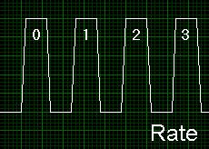
7 Digital Signal Information Two types of information: State Rate


8 Analog Signal Information Three types of information: Level Shape Frequency
9 Considerations for analog signals Signal source - grounded or floating Source impedance The DAQ device must have a much higher input impedance than the signal source This is usually not a problem as the DAQ devices are designed to have a very high input impedance (GΩ range) Single-ended & differential signals V in I = V / Z
10 Signal Source Categories Grounded Floating + V s _ + V s _
11 Grounded Signal Source Grounded + V s _ Signal is referenced to a system ground earth ground building ground Examples: Power supplies Signal Generators Anything that plugs into an outlet ground
12 Floating Signal Source Signal is NOT referenced to a system ground earth ground building ground Examples: Batteries Thermocouples Transformers Isolation Amplifiers Floating + V s _
13 DAQ-card input signal configuration DAQ input channels can be configured in two ways: Differential Single-ended Referenced Single-Ended (RSE) Non-Referenced Single-Ended (NRSE) The optimal connection depends on how your signal is grounded
14 Single-ended (SE) signals One signal wire for each input signal Can be used for the following conditions: High-level input signals (greater than 1 V) Short cables Properly-shielded cables or cables traveling through a noise-free environment All input signals can share a common reference point (ground) To types of connections: Referenced Single-Ended (RSE) Non-Referenced Single-Ended (NRSE)
15 RSE vs. NRSE configuration The RSE configuration is used for floating signal sources. In this case, the DAQ hardware device itself provides the reference ground for the input signal. The NRSE input configuration is used for grounded signal sources. In this case, the input signal provides its own reference ground and the hardware device should not supply one. Measurement made with respect to a common reference (AISENSE), not system ground (AIGND) AISENSE is floating RSE NRSE
16 Ground loop illustration The blue connection to ground must not be added, since it creates a ground loop RSE Ig Rg ΔVg Ground loop!
17 Differential signals Two signal wires for each input signal (input and return signals) The measurement is the voltage difference between the two wires Recommended for the following conditions: Low-level signals (less than 1 V) Long cables The input signal requires a separate ground-reference point or return signal The signal leads go through a noisy environment DAQ devices with instrumentation amplifiers can be configured as differential measurement systems Any voltage present at the instrumentation amplifier inputs with respect to the amplifier ground is called a common-mode voltage The instrumentation amplifier rejects common-mode voltage and common-mode noise Input signal Return signal

18 Options for Grounded Signal Sources

19 Options for Floating Signal Sources
20 Signal conditioning Signal conversion E.g. current-voltage converter Amplification Attenuation Voltage divider Filtering Anti-aliasing Isolation
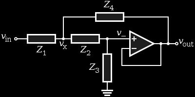
21 Current-to-voltage converter Transimpedance amplifier (Feedback Ammeter) Recommended connection for small currents Sensitivity determined by Rf Add a capacitor Cf in parallel with Rf to avoid oscillations Rf usually large to achieve a large gain e nb dominate for large Rf Noise equivalent circuit: e nb = input current noise * Rf e nv = input voltage noise e nj = thermal noise (voltage)
22 Amplification Used on low-level signals (less than around 100 mv ) Maximizes use of Analog-to-Digital Converter (ADC) range and increases accuracy Increases Signal to Noise Ratio (SNR) Noise 1 mv Instrumentation Amplifier E.g. -5 V to +5 V + _ 10 mv V Lead Wires ADC Low-Level Signal External Amplifier DAQ Device SNR = V signal /V noise = (10 mv * 1000) /1 mv =
23 Operational amplifier (Op-amp) Inverting op-amp amplifier Vo = -R2/R1 * Vi Non-inverting op-amp amplifier Vo = (1+R2/R1) * Vi Non-inverting op-amp amplifier useful when a high impedance input is needed Inverting op-amp amplifier useful when a low impedance input is needed Non-inverting op-amp amplifier gives less noise (due to G = 1+R2/R1 instead of G = -R2/R1
24 Attenuation Voltage divider A circuit that produces an output voltage (V out ) that is a fraction of its input voltage (V in ) Can be needed to get a high-level signal down to the acceptable DAQ-card range
25 Input Coupling Use AC coupling when the signal contains a large DC component. If you enable AC coupling, you remove the large DC offset for the input amplifier and amplify only the AC component. This configuration makes effective use of the ADC dynamic range C

26 Isolation amplifiers Isolation electrically separates two parts of a measurement device Protects from high voltages Prevents ground loops when two connected points are at a different ground potential, creating a current flow in the interconnection, which produces an offset error Separate ground planes of data acquisition device and sensor Isolation techniques: Optical, Capacitive, Inductive Coupling 8.5 V 7 V
27 Before we look at hardware filtering, lets have a look at sampling concepts.
28 Sampling Considerations An analog signal is continuous A sampled signal is a series of discrete samples acquired at a specified sampling rate The faster we sample the more our sampled signal will look like our actual signal Actual Signal If not sampled fast enough a problem known as aliasing will occur Sampled Signal
29 Aliasing Adequately Sampled Signal Signal Aliased Signal
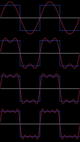
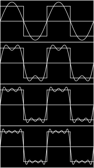
30 Sampling & Nyquist s Theorem Nyquist s Theorem You must sample at greater than 2 times the maximum frequency component of your signal to accurately represent the frequency of your signal NOTE: You must sample between 5-10 times greater than the maximum frequency component of your signal to accurately represent the shape of your signal
31 Sampling Example Aliased Signal 100Hz Sine Wave Sampled at 100Hz Adequately Sampled for Frequency Only (Same # of cycles) 100Hz Sine Wave Sampled at 200Hz 100Hz Sine Wave Sampled at 1kHz Adequately Sampled for Frequency and Shape
32 Hardware Filtering Filtering To remove unwanted signals from the signal that you are trying to measure Anti-aliasing low-pass filtering (before the A/D converter) To remove all signal frequencies that are higher than the input bandwidth of the device. If the signals were not removed, they would erroneously appear as signals within the input bandwidth of the device (known as aliasing) Frequency Domain:
 Some common filter characteristics Butterworth Chebyshev Bessel (constant group delay in pass band) Elliptic Bessel")
33 Analog filters Filter types: LP, HP, BP, BS, Notch Passive filters: RC, LCR (often inductors L are avoided, but they are needed for high Q-factor) Active filters opamp + R and C (can avoid L) Some common filter characteristics Butterworth Chebyshev Bessel (constant group delay in pass band) Elliptic Bessel

34 Sallen-Key - Active analog filter Free program: FilterPro from Texas instruments LP HP
35 Switched-Capacitor Filter Can be suitable as an ADC anti-aliasing filter if you build your own electronics Be aware of possible clock noise (add RC-filters before and after) The corner frequency (cut-off) fc is programmable using an external clock Example: MAX7400 8th-order,lowpass, elliptic filter MAX7400 has a transition ratio (fs/fc) of 1.5 and a typical stop band rejection of 82dB
36 Importance of LP-filter selection for DAQ bandwidth fc = cut-off frequency fs = sampling frequency BW = bandwidth M (db) 0-3 BW A lowpass (LP) filter with a small transition band gives a wider passband/bw with a given sample frequency f s and a defined stopband starting at f stop M stop fc fc f stop f (Hz) fs = 2*fc fs = 2*f stop fs = 5*fc (in this example)

37 ADC architectures Multiplexed Simultaneous sampling
38 ADC resolution The number of bits used to represent an analog signal determines the resolution of the ADC Larger resolution = more precise representation of your signal The resolution determine the smallest detectable change in the input signal, referred to as code width or LSB (least significant bit) Example: Amplitude 5.00 (volts) Bit Versus 3-Bit Resolution (5kHz Sine Wave) bit resolution 3-bit resolution Time (ms)


39 Digital signals: Bits, dynamic range, and SNR SNR = signal to noise ratio The number of bits used determines the maximum possible signal-to-noise ratio Using the entire ADC range (using an amplifier) increases the SNR The minimum possible noise level is the error caused by the quantization of the signal, referred to as quantization noise.
 = 6.02*N + 1.")
, where N is the")
40 ADC oversampling Δf The SNR of an ideal N-bit ADC (due to quantization effects) is: SNR(dB) = 6.02*N If the sampling rate is increased, we get the following SNR: SNR(dB) = 6.02*N * log 10 (OSR) OSR = f s /f nyquist 0 Δf Nyquist sampling theorem: f s 2 *Δf signal Δf signal = f high - f low Oversampling makes it possible to use a simple RC anti-aliasing filter before the ADC After A/D conversion, perform digital low-pass filtering and then down sampling to f nyquist Effective resolution with oversampling = N + 1/2 *log 2 (f s /f nyquist ), where N is the resolution of an ideal N-bit ADC at the Nyquist rate If OSR = f s /f nyquist = 1024, an 8-bit ADC gets and effective resolution equal to that of a 13-bit ACD at the Nyquist rate (which is 2 *Δf signal ) 0 f
41 ADC range Range refers to the minimum and maximum analog signal levels that the ADC can digitize (+/-5 or +/-10 typical for many DAQ-cards) Pick a range that your signal fits in Smaller range gives a more precise representation of your signal, given that the signal is not clipped (saturated) If your signal is clipped you can in general not determine the absolute signal levels Bipolar signals are signals that range from a negative to a positive value (e.g. -5 to +5 V) Unipolar signals are signals that range from 0 value to a positive value (e.g. 0 5 V)
42 Gain Gain setting amplifies the signal for best fit in ADC range Gain settings are 0.5, 1, 2, 5, 10, 20, 50, or 100 for most DAQ cards. You don t choose the gain directly in LabVIEW Choose the input limits of your signal Maximum gain possible is selected Maximum gain possible depends on the limits of your signal and the range of your ADC Proper gain = more precise representation of your signal Allows you to use all of your available resolution
43 Gain Example Input limits of the signal: 0 to 5 Volts Range setting for the ADC: 0 to 10 Volts Gain setting applied by instrumentation amplifier: 2 Amplitude (volts) Different Gains for 16-bit Resolution (5kHz Sine Wave) Time (ms) Gain = 2 Your Signal Gain = 1
 away from data acquisition device, cable, and sensor if possible Place data acquisition device as close to sensor as possible to prevent noise")
44 Other noise reduction techniques in DAQ systems Position noise sources (e.g. motors and power lines) away from data acquisition device, cable, and sensor if possible Place data acquisition device as close to sensor as possible to prevent noise from entering the system Twisted pairs, coax cable, shielding Software Filtering (e.g. averaging)


45 Software filtering Easy, flexible, predictable, inexpensive Unable to distinguish aliased signals from true ones Need a hardware anti-aliasing filter before the A/D conversion! Modern PCs have plenty of CPU speed for software filtering

46 Data Acquisition Hardware Plug-in card (PCI/PCIe) Signal DAQ Device Computer Cable Terminal Block DAQ Hardware turns the PC into a measurement and automation system
 Computer Connects to the bus of your computer Compatible with a variety of bus protocols PCI, PXI, CompactPCI, PCIe, PXIe, PCMCIA,")
47 DAQ Device Most DAQ devices have: Analog Input Analog Output Digital I/O Counters DAQ Device Frequency measurements (digital edge counting) Angular measurements from angular encoders (quadrature encoders) Computer Connects to the bus of your computer Compatible with a variety of bus protocols PCI, PXI, CompactPCI, PCIe, PXIe, PCMCIA, USB
48 PXI PXI = PCI extensions for Instrumentation. PXI is a high-performance PC-based platform for measurement and automation systems. PXI was developed in 1997 and launched in Today, PXI is governed by the PXI Systems Alliance (PXISA), a group of more than 70 companies chartered to promote the PXI standard, ensure interoperability, and maintain the PXI specification.


49 PXI PXI systems are composed of three basic components: Chassis Controller Peripheral modules

50 PXI chassis The PXI chassis contains the backplane for the plug-in DAQ cards The chassis provides power, cooling, and communication buses for the PXI controller and modules. Chassis are available both with PCI and PCI Express 4 18 slots chassis are common


51 PXI controllers PXI Embedded Controller Can run Windows or/and real-time OS Laptop Control of PXI Using e.g. ExpressCard serial bus Desktop PC Control of PXI > 800 MB/s possible (MXI bus)
52 PXI-based DAQ systems The benefits of PXI-based data acquisition systems include rugged packaging that can withstand the harsh conditions that often exist in industrial applications. PXI systems also offer a modular architecture, which means that you can fit several devices in the same space as a single stand-alone instrument, and you have the ability to expand your system far beyond the capacity of a desktop computer with a PCI bus.


53 PXI triggering and timing One of the key advantages of a PXI system is the integrated timing and synchronization. The PXI chassis includes reference clocks, triggering buses and slot-toslot local bus. Any module in the system can set a trigger that can be seen from any other module. The local bus provides a means to establish dedicated communication between adjacent modules.
54 Device Drivers In computing, a device driver or software driver is a computer program allowing higher-level computer programs to interact with a hardware device. A driver typically communicates with the device through the computer bus or communications subsystem to which the hardware connects. When a calling program invokes a routine in the driver, the driver issues commands to the device. Once the device sends data back to the driver, the driver may invoke routines in the original calling program. Drivers are hardwaredependent and operating-system-specific.

55 NI Instrument Drivers - IDNET All NI hardware is shipped with LabVIEW driver software Driver upgrade to the latest version available at Many third-party vendors also ship LabVIEW drivers with their instruments ni.com/idnet
.")
56 Using device drivers in LabVIEW The flow of an application typically starts with opening a connection to the hardware, configuring hardware settings, reading and writing measured data to and from the hardware, and finally closing the connection to the hardware. Always do hardware configuration only once (e.g. outside the while-loop). To modes to choose: High-level, easy-to-understand operations (Plug and Play) Lower-level operations required to use more advanced features
57 In Port and Out Port in LabVIEW Use these VIs only for 16-bit I/O addresses These VIs are not available in Windows Vista or Windows 7, because it allows read/write access to any I/O port on the system, which is discouraged for security reasons. Solution: Use VISA
58 VISA VISA = Virtual Instrument Software Architecture. NI-VISA is the NI implementation of the VISA standard. LabVIEW instrument drivers are based on the VISA standard, which makes them bus- and platform-independent. Supports communication with instruments via: GPIB Serial Ethernet USB PXI

59 NI-DAQmx NI-DAQmx (multithreaded driver) software provides ease of use, flexibility, and performance in multiple programming environments Driver level software DLL that makes direct calls to your DAQ device Supports the following software: NI LabVIEW NI LabWindows CVI C/C++ C# Visual Basic.NET.

60 NI Measurement & Automation Explorer (MAX) Icon on your Desktop All NI-DAQmx devices include MAX, a configuration and test utility You can use MAX to Configure and test NI-DAQmx hardware with interactive test panels Perform self-test sequences Create simulated devices Reference wiring diagrams and documentation Save, import, and export configuration files Create NI-DAQmx virtual channels that can be referenced in any programming language

61 MAX Example


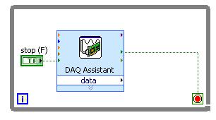
62 LabVIEW Express: DAQ assistant Using the the DAQ assistant is the easy way to configure and read from a DAQ card!
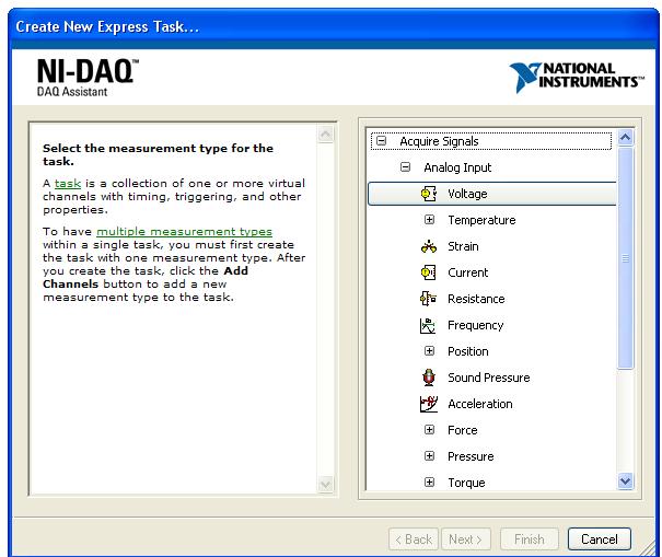
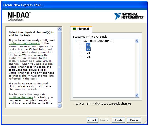
63
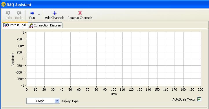
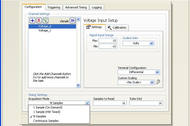
64

65 LabVIEW - Sequential DAQ design Configure Acquire data Analyze data Visualize data Store data

66 LabVIEW: Low-speed DAQ DAQ assistant Express VI used in the block diagram Data written to file using the Write to Measurement File Express VI

67 Using the NI-DAQmx API Create virtual channels programmatically Use graphical functions and structures to specify timing, triggering, and synchronization parameters For advanced user use the DAQ assistant easy configuration!

68 DAQ Assistant -> standard VIs

69 LabVIEW: Medium-speed DAQ Example: Cont Acq&Graph Voltage -To File (Binary).vi Standard VIs used, and data written to a binary file Create file Create header Write Close file Create analog input channel Set sample rate Start acquisition Read data Stop acquisition
 buffer. Data is transferred from the FIFO buffer to system memory using interrupts or DMA.")
70 Transferring Data from DAQ-card to System Memory The transfer of acquired data from the hardware to system memory follows these steps: Acquired data is stored in the hardware's first-in first-out (FIFO) buffer. Data is transferred from the FIFO buffer to system memory using interrupts or DMA. The samples are transferred to system memory via the system bus (PCI/PCIe).
71 Interrupts The slowest method to move acquired data to system memory is for the DAQ-card to generate an interrupt request (IRQ). signal. This signal can be generated when one sample is acquired or when multiple samples are acquired. The process of transferring data to system memory via interrupts is given below: When data is ready for transfer, the CPU stops whatever it is doing and runs a special interrupt handler routine that saves the current machine registers, and then sets them to access the board. The data is extracted from the board and placed into system memory. The saved machine registers are restored, and the CPU returns to the original interrupted process. The actual data move is fairly quick, but there is a lot of overhead time spent saving, setting up, and restoring the register information.
72 DMA introduction Direct memory access (DMA) is a system whereby samples are automatically stored in system memory while the processor (CPU) does something else. A computer usually supports several different DMA channels.
73 DMA (direct memory access) I DMA permits peripherals, such as a DAQ-card, to transfer data directly to or from memory without having each byte handled by the processor (CPU). Thus DMA enables more efficient use of interrupts, and increases data throughput. The process of transferring data via DMA is given below: When data is ready for transfer, the DAQ-card notifies the DMA controller. The DMA controller then asserts a DMA request signal to the CPU, asking its permission to use the bus (data bus, address bus, control bus). The CPU completes its current bus activity, stops driving the bus, and returns a DMA acknowledge signal to the DMA controller. The DMA controller then reads and writes one or more memory bytes, driving the address, data, and control signals as if it were itself the CPU. DMA intro
74 DMA (direct memory access) II When the transfer is complete, the DMA controller stops driving the bus and deasserts the DMA request signal. The CPU can then remove its DMA acknowledge signal and resume control of the bus. In single-cycle mode, the DMA controller gives up the bus after each transfer. This minimizes the amount of time that the DMA controller keeps the processor off of the memory bus, but it requires that the bus request/acknowledge sequence be performed for every transfer. This overhead can result in a drop in overall system throughput if a lot of data needs to be transferred. In burst mode, the DMA controller keeps control of the bus until all the data buffered by the requesting device has been transferred to memory (or when the output device buffer is full, if writing to a peripheral).
 is configured, DAQmx configures the board for hardwared-timed I/O DAQ card sample clock or external sample clock By enabling continuous sampling DAQmx automatically sets up a circular buffer DMA")
75 LabVIEW DAQ - hardware setup When the sample clock (DAQmx Timing.vi) is configured, DAQmx configures the board for hardwared-timed I/O DAQ card sample clock or external sample clock By enabling continuous sampling DAQmx automatically sets up a circular buffer DMA is the default method of data transfer for DAQ devices that support DMA Circular buffer Data acquisition card DMA transfer RAM (in the PC) Data ADC FIFO buffer Data PC buffer Application memory From sensor sclk To PC buffer
76 DAQ data overwrite and overflow An overwrite error indicates that information is lost and occurs when the software program does not read data from the PC buffer quickly enough. Samples that are written to the circular PC buffer are overwritten before they are read into the application memory. Solution: use Producer-Consumer architecture. An overflow error indicate that information has been lost earlier in the data acquisition process. Overflow errors indicate that the First In First Out (FIFO) memory buffer onboard the data acquisition card has reached its maximum capacity for storing acquired samples and can no longer accept new samples. An overflow error is symptomatic of a bus transfer rate that falls short of the requested data input rate. Solution: use a Direct Memory Access (DMA) transfer mechanism.
77 How Is Buffer Size Determined in LabVIEW DAQmx? If the acquisition is continuous (sample mode in DAQmx Timing.vi set to Continuous Samples), NI-DAQmx allocates a PC buffer equal in size to the value of the samples per channel (gives the number of samples to acquire) property, unless that value is less than the value listed in the following table. If the value of the samples per channel property is less than the value in the table below, NI- DAQmx uses the value in the table. Sample Rate No rate specified PC Buffer Size 10 ks S/s 1 ks ,000 S/s 10 ks 10,001 1,000,000 S/s 100 ks >1,000,000 S/s 1 MS You can override the default buffer size using the function DAQmx Configure Input Buffer.vi

78 High-speed DAQ Solve the DAQ related problems listed on the next slide! Based on the producer-consumer architecture See the high-speed streaming lecture for more information! Producer loop Hardware timing, since no Wait function is used in the producer loop. The producer loop rate is given by the DAQ-card setup f sample rate (Hz) producer = DAQ card buffer size Consumer loop
79
80 LabVIEW Timed Loop 1 khz internal clock (Windows) 1 MHz internal clock (for RT-targets) A Timed Loop gives you: possibility to start the loop at a precise time (using a time stamp) phase (offset) control possibility to specifies the processor you want to handle execution execution priority precise determinism in a real-time operating system When Timed Loops as used on Windows (no RTOS) the OS can preempt your structure at any time to let a low-priority task run (based on fairness!

81 Execution priority In LabVIEW while loops run at normal priority, and timed loops run between time-critical priority and above high priority. Therefore if you would like to have control of the priority of each aspect of your application you can use timed loops, and set the priority between them using the priority input File - VI Properties»Execution:
 you have to use a hardware solution ( software in the loop degrades")
82 Software Timing Attempts to resolve milliseconds on a PC within the limitations of the operating system (such as Windows) If you need better resolution or accuracy (determinism) you have to use a hardware solution ( software in the loop degrades precision)
83 Hardware Timing Necessary for high-resolution and high-accuracy timing e.g. for data correlation Hardware timing can give ns to µs accuracy (recall that software timing gives accuracy in the ms range) Using GPS you can get a time uncertainty in the range of ns Ordinary DAQ-cards includes a stable crystal oscillator (for the ADC) that gives a resolution of µs or better, and this can be used for timing
84 Trigger (from hardware or software) A trigger is a signal that causes a device to perform an action, such as starting an acquisition. You can program your DAQ device to generate triggers on any of the following: a software command (software trigger) a condition on an external digital signal a condition on an external analog signal E.g. level triggering

85 Trigger types Start trigger E.g. start data acquisition when an external digital signal have a rising edge Pre-trigger Include a specified number of samples before the trigger event Useful for high speed imaging Need a data buffer Post-trigger Wait a specified number of samples after the trigger event before samples are acquired.
 interval, such as samples from a DAQ-card, it is sufficient to time stamp the first sample at time t 0 : t 0 = T OSretrieval t (number of samples) t")
86 Time stamping of data Often need to timestamp an image in a video stream or a block of data from a DAQ-card to GPS (UTC) time; e.g. for use in data fusion in post-analysis. If the data samples has a deterministic (regular) interval, such as samples from a DAQ-card, it is sufficient to time stamp the first sample at time t 0 : t 0 = T OSretrieval t (number of samples) t delay Given t 0 the time of the remaining samples are found from: t = t0 + n t t = 1 fs If the data samples are not deterministic (regular), e.g. video frames from a camera, each data point/video frame must include a timestamp
87 Signal based vs. time-based synchronization Signal-based synchronization involves sharing signals such as clocks and triggers directly (wires) between nodes that need to be synchronized. Time-based synchronization involves nodes independently synchronizing their individual clocks based on some time source, or time reference. There are advantages and disadvantages to both methods of device synchronization. Synchronization Basics

88 Signal-based synchronization In systems where the devices are near each other, sharing a common timing signal is generally the easiest and most accurate method of synchronization. For example, modular instruments in a PXI chassis all share a common 10 MHz clock signal from the PXI backplane. To accurately use a common timing signal, a device must be calibrated to account for the signal propagation delay from the timing source to the device
 clocks, distributed clocks must be")

89 Time-based synchronization Necessary for long distances Because of the inherent instabilities in (crystal oscillator) clocks, distributed clocks must be synchronized continuously to a time refererence to match each other in frequency and phase. Time references: GPS IEEE 1588 master IRIG-B sources Timing and Synchronization Systems
90 How good is a crystal oscillator (XO)? Interested in the long-term measurement stability and accuracy Watch crystal oscillator: about 20 ppm, or worse Error > 1.73 s in 24 hours (almost 1 minute drift in one month) The accuracy can be improved using a: Temperature compensated crystal oscillator (TCXO) Oven controlled crystal oscillator (OCXO) the oscillator is enclosed in a temperature controlled oven Some DAQ card accuracy examples: TCXO : 1 ppm OCXO: 50 ppb
91 Global time possible implementations Reference clock Reference clock Reference clock Time response Time request Time Δt (Time Error) Time Computer clock Computer clock Computer clock

92 IRIG serial time codes IRIG = Inter Range Instrumentation Group (a standard) Several time codes, but IRIG-B is the most common Both AM and DC versions of the code Best time accuracy with DC AM best for transmission over long cables Accuracies of the order of a few microseconds or better IRIG-B AM AM = Amplitude Modulation BCD = Binary Coded Decimal IRIG-B DC
93 Network Time Protocol (NTP) NTP is a protocol designed to synchronize the clocks of computers over a network. Can provide accuracies of better than 10 ms over Ethernet. accuracy depends on the network (local area network vs. Internet) User Datagram Protocol (UDP) is used. Edited from Wikipedia: GPS with NTP-server and IRIG-B output NTP can usually maintain time to within tens of milliseconds over the public Internet, and can achieve better than one millisecond accuracy in local area networks under ideal conditions. Network problems can cause errors of 100 ms or more All Microsoft Windows versions since Windows 2000 and Windows XP include the Windows Time Service, which has the ability to sync the computer clock to an NTP server. The version in Windows 2000 and Windows XP only implements Simple NTP (SMTP), and violates several aspects of the NTP version standard. Beginning with Windows Server 2003 and Windows Vista, a compliant implementation of full NTP is included.
94 IEEE 1588 Protocol Gives sub-microsecond synchronization in distributed systems IEEE 1588 provides a standard protocol for synchronizing clocks connected via a multicast capable network, such as Ethernet. uses a protocol known as the precision time protocol (PTP). All participating clocks in the network are synchronized to the highest quality clock in the network. The highest ranking clock is called the grandmaster clock, and synchronizes all other slave clocks. The level of precision achievable using PTP (Precision Time Protocol) depends heavily on the jitter (the variation in latency) present in the underlying network topology. Point-to-point connections provide the highest precision.
95 GPS & IEEE 1588 used for time synchronization of multiple PCs GPS antenna IRIG-B IEEE1588
96
97 Time-based synchronization in LabVIEW Install the NI-Sync drivers Example: Time Reference (e.g. IEEE 1588, GPS or IRIG-B)
98 Advanced DAQ with multiple while loops A DAQ program usually have several while loops running in parallel, and data (and messages) should be distributed between the loops using queues Sample project in LabVIEW queued message handler
99 Postrun analysis / Quicklook tool Usually not sufficient to only look at the data in real-time (live) Usually very important to look at the data (perform a playback) as soon as possible after a data acquisition E.g. to check the quality of the data It is very useful to have the Quicklook (playback) and analysis functions integrated in the data acquisition program! It should also be possible to read the measurement data by other common post-analysis tools (like Matlab)


 to")

100 Tracking Example: VISION Example: Configuration of a GigE Vision camera Use MAX (and the camera manual) to find the commands to configure the camera Airbag deployment test

101 Vision time stamping example GE680C Visual camera (205 fps) Question: How to accurately time stamp each image from a camera to GPS time, without any delay added from the software loop? Possible configurations of sync out: sync out Image ref. Loop time stamp is not equal to image sample time!
102 Can timestamp the rising edge of the signal using e.g. the NI PXI 6683 card (GPS, IEEE 1588 and IRIG-B)
PC-based data acquisition I
 FYS3240 PC-based instrumentation and microcontrollers PC-based data acquisition I Spring 2016 Lecture #8 Bekkeng, 20.01.2016 General-purpose computer With a Personal Computer (PC) we mean a general-purpose
Advanced NI-DAQmx Programming Techniques with LabVIEW
 Advanced NI-DAQmx Programming Techniques with LabVIEW Agenda Understanding Your Hardware Data Acquisition Systems Data Acquisition Device Subsystems Advanced Programming with NI-DAQmx Understanding Your
FYS Data acquisition & control. Introduction. Spring 2018 Lecture #1. Reading: RWI (Real World Instrumentation) Chapter 1.
 Chapter 1.") FYS3240-4240 Data acquisition & control Introduction Spring 2018 Lecture #1 Reading: RWI (Real World Instrumentation) Chapter 1. Bekkeng 14.01.2018 Topics Instrumentation: Data acquisition and control
FYS3240-4240 Data acquisition & control Introduction Spring 2018 Lecture #1 Reading: RWI (Real World Instrumentation) Chapter 1. Bekkeng 14.01.2018 Topics Instrumentation: Data acquisition and control
CompuScope Ultra-fast waveform digitizer card for PCI bus. APPLICATIONS. We offer the widest range of
 We offer the widest range of high-speed and high-resolution digitizers available on the market CompuScope 1602 Ultra-fast waveform digitizer card for PCI bus today. Our powerful PC-based instrumentation
USB 1608G Series USB Multifunction Devices
 USB Multifunction Devices Features 16-bit high-speed USB devices Acquisition rates ranging from 250 ks/s to 500 ks/s differential (DIFF) or 16 singleended (SE) analog inputs (softwareselectable) Up to
The Concept of Sample Rate. Digitized amplitude and time
 Data Acquisition Basics Data acquisition is the sampling of continuous real world information to generate data that can be manipulated by a computer. Acquired data can be displayed, analyzed, and stored
E Series Multifunction I/O 1.25 MS/s, 12-Bit, 16 or 64 Analog Inputs
 E Series Multifunction I/O 1.25 MS/s, 12-Bit, 16 or 64 Inputs Families (E-1) Families (E-1) Family (MIO-16E-1) PCI-MIO-16E-1 PXI- AT-MIO-16E-1 Family (MIO-64E-1) PCI- PXI- VXI-MIO-64E-1 Input 16 single-ended,
Product Information Sheet PX Channel, 14-Bit Waveform Digitizer
 Product Information Sheet PX14400 2 Channel, 14-Bit Waveform Digitizer FEATURES 2 Analog Channels at up to 400 MHz Sample Rate per Channel 14 Bits of Resolution Bandwidth from 100 KHz to 400 MHz 1 Gigabyte
LabVIEW programming II
 FYS3240 PC-based instrumentation and microcontrollers LabVIEW programming II Spring 2016 Lecture #3 Bekkeng 18.01.2016 Dataflow programming With a dataflow model, nodes on a block diagram are connected
Data Acquisition Specifications a Glossary Richard House
 NATIONAL INSTRUMENTS The Software is the Instrument Application Note 092 Introduction Data Acquisition Specifications a Glossary Richard House This application note consists of comprehensive descriptions
USB 1608G Series USB Multifunction Devices
 USB Multifunction Devices Features 16-bit high-speed USB devices Acquisition rates ranging from 250 ks/s to 500 ks/s differential (DIFF) or 16 singleended (SE) analog inputs (softwareselectable) Up to
LabVIEW Basics I: Introduction Course
 www.ni.com/training LabVIEW Basics I Page 1 of 4 LabVIEW Basics I: Introduction Course Overview The LabVIEW Basics I course prepares you to develop test and measurement, data acquisition, instrument control,
The hardware implementation of PXI/PXIe consists of a chassis, controller or computer interface, and peripheral cards.
 Introduction PCI extensions for Instrumentation or PXI is a computer based hardware and software platform for test and measurement systems. Developed in the late 1990 s as an open industry standard based
DIGITAL SYSTEM. Technology Overview Nordco. All rights reserved. Rev C
 DIGITAL SYSTEM Technology Overview Rev C 01-05-2016 Insert Full Frame Product Picture Here 2015 KEY FEATURES DIGITAL PROCESSING SYSTEM FOR INDUSTRIAL & TONNE UE SYSTEM DIGITAL PROCESSING SYSTEM FOR MICRO
Figure 3.174: Illustration of the code of the event f USB that plots an USB camera frame if the typed frame is under the acceptable limits (case 0)
") 107 Figure 3.174: Illustration of the code of the event f USB that plots an USB camera frame if the typed frame is under the acceptable limits (case 0) Typing the desired HS frame in the box f HS, it is
107 Figure 3.174: Illustration of the code of the event f USB that plots an USB camera frame if the typed frame is under the acceptable limits (case 0) Typing the desired HS frame in the box f HS, it is
A variety of ECONseries modules provide economical yet flexible solutions. Waveform Generation
 ECONseries BUS: USB Type: Economy, Mini-Instruments ECONseries Economy USB Mini-Instruments Flexible Yet Economical A variety of low-cost ECONseries modules are available to provide flexible yet economical
PXI - An ideal platform for a variety of industrial applications
 PXI - An ideal platform for a variety of industrial applications Overview This white paper explains in detail the PXI architecture and discusses the benefits PXI systems present in a variety of industrial
Computerized Measurement systems
 Elektrisk Mätteknik, LTH Computerized Measurement systems 1. Introduction to Computerized measurements systems By Tomas Jansson, some text excerpts from NI application note AN007 regarding signal conditioning,
DaqBoard/1000. Series 16-Bit, 200-kHz PCI Data Acquisition Boards
 16-Bit, 200-kHz PCI Data Acquisition Boards Features 16-bit, 200-kHz A/D converter 8 differential or 16 single-ended analog inputs (software selectable per channel) Up to four boards can be installed into
PXI Remote Control and System Expansion
 Have a question? Contact Us. PRODUCT FLYER PXI Remote Control and System Expansion CONTENTS PXI Remote Control and System Expansion Components of a Remotely Controlled PXI System Choosing a Remote Control
How to Choose the Right Bus for Your Measurement System
 1 How to Choose the Right Bus for Your Measurement System Overview When you have hundreds of different data acquisition (DAQ) devices to choose from on a wide variety of buses, it can be difficult to select
PC104P-24DSI Channel 24-Bit Delta-Sigma PC104-Plus Analog Input Board
 PC104P-24DSI12 12-Channel 24-Bit Delta-Sigma PC104-Plus Analog Input Board With 200 KSPS Sample Rate per Channel and Optional Low-Power Configuration Available also in PCI, cpci and PMC form factors as:
High-Value PXI Embedded Controller for Windows. High-Value Embedded Controllers for PXI Express NI PXI-8101, NI PXI NI PXIe-8101, NI PXIe-8102
 High-Value PXI Embedded Controller for Windows NI PXI-8101, NI PXI-8102 2.0 GHz single-core for PXI-8101, 1.9 GHz dual-core for PXI-8102 1 GB (1 x 1 GB DIMM) 800 MHz DDR2 RAM standard, 4 GB (1 x 4 GB DIMMs)
DT9828. USB Powered Thermocouple Measurement Module. Key Features: Analog Input Channels
 DT9828 USB Powered Thermocouple Measurement Module Key Features: 8 differential analog inputs for thermocouple or voltage measurements Support for B, E, J, K, N, R, S, and T thermocouple types One cold
Portable E Series Multifunction DAQ 12 or 16-Bit, up to 1.25 MS/s, 16 Analog Inputs
 Portable E Series Multifunction DAQ 12 or 16-Bit, up to 1.25 MS/s, 16 Analog Inputs E Series Portable 16 analog inputs at up to 1.25 MS/s, 12 or 16-bit resolution Up to 2 analog outputs at up to 1 MS/s,
Analog Input Sample Rate
 ECONseries Low Cost USB Data Acquisition Modules Overview The ECONseries is a flexible yet economical series of multifunction DAQ modules. You chse the number of analog I/O and digital I/O channels, the
DAQ & Control with PXI. Murali Ravindran Senior Product Manager
 DAQ & Control with PXI Murali Ravindran Senior Product Manager Agenda What is PXI? Trigger with PXI Multicore Programming DAQ & Control with FPGA Instrumentation Timeline 1965 1987 1995 1997 Photo Courtesy
Computer buses and interfaces
 FYS3240-4240 Data acquisition & control Computer buses and interfaces Spring 2018 Lecture #7 Reading: RWI Ch7 and page 559 Bekkeng 14.02.2018 Abbreviations B = byte b = bit M = mega G = giga = 10 9 k =
DT MS/s High-Speed, Isolated Simultaneous USB Data Acquisition Module. Overview. Key Features. Bandwidth of the DT9862
 DT9862 10 MS/s High-Speed, Isolated Simultaneous USB Data Acquisition Module Overview The DT9862 is a high-speed, high-performance USB data acquisition module that provide throughput rates up to 10 MS/s
DT8824 High Stability, High Accuracy, Ethernet Instrument Module
 DT8824 High Stability, High Accuracy, Ethernet Instrument Module The DT8824 Ethernet data acquisition (DAQ) module offers the highest stability and accuracy for measuring analog signals. Every signal input,
PCI-express data acquisition card DAQ0504M User Guide
 PCI-express data acquisition card DAQ0504M User Guide Contents Safety information... 3 About this guide... 4 DAQ0504M specifications... 5 Chapter 1. Product introduction 1-1. Package contents...... 6.
The PXI Modular Instrumentation Architecture
 The PXI Modular Instrumentation Architecture Overview The PXI (PCI extensions for Instrumentation) specification defines a rugged PC platform for measurement and automation. PXI modular instrumentation
DT9800 Series. USB Function Module for Data Acquisition
 DT9800 Series USB Function Module for Data Acquisition True plug-and-play: Key Features One cable supplies both power and all connections to the USB module. All connections are external so you do not need
Product Information Sheet PDA14 2 Channel, 14-Bit Waveform Digitizer APPLICATIONS FEATURES OVERVIEW
 Product Information Sheet PDA 2 Channel, -Bit Waveform Digitizer FEATURES 2 Channels at up to 100 MHz Sample Rate Bits of Resolution Bandwidth from DC-50 MHz 512 Megabytes of On-Board Memory 500 MB/s Transfer
cpci6u64-20aof16c500kr
 cpci6u64-20aof16c500kr 20-Bit 16-Output 500KSPS Precision Wideband cpci 6U Analog Output Board With 8th-Order reconstruction output filters Features Include: 16 Single-ended or optional 3-Wire Differential
PCIe-16AOF Bit, 64/32-Channel, 500KSPS PCI Express Analog Output Board. With Reconstruction Output Filters
 PCIe-16AOF64 16-Bit, 64/32-Channel, 500KSPS PCI Express Analog Output Board With Reconstruction Output Filters Features Include: Precision 16-Bit simultaneously-clocked analog outputs: R-2R DAC per channel
Features. RoHS COMPLIANT 2002/95/EC
 PCIE-1730 32-ch TTL and 32-ch Isolated Digital I/O PCI Express Card 32-ch isolated DI/O (16-ch digital input, 16-ch digital output) 32-ch TTL DI/O (16-ch digital input,16-ch digital output) High output
DT9837. High Performance USB Module for Sound & Vibration Analysis. DT9837 Features
 DT9837 High Performance USB Module for Sound & Vibration nalysis DT9837 Features 4 simultaneous, 24-bit Delta-Sigma channels for high resolution measurements. Support for four IEPE inputs, including current
Chapter 1 Introducing the OM-USB-1608FS-Plus... 6 Functional block diagram... 6
 Table of Contents Preface About this User's Guide... 5 What you will learn from this user's guide... 5 Conventions in this user's guide... 5 Where to find more information... 5 Chapter 1 Introducing the
Overview: Functional Description:
 CPCI-ADADIO 12-Channel 16-Bit Analog I/O CPCI Card With 8 Simultaneous Input Channels at 200K Samples per Second per Channel, 4 Output Channels, and Byte-Wide Digital I/O Port Features Include: 8 Analog
Digital electronics & Embedded systems
 FYS3240 PC-based instrumentation and microcontrollers Digital electronics & Embedded systems Spring 2017 Lecture #10 Bekkeng, 30.1.2017 Embedded systems An embedded system is a special-purpose system designed
Software-Defined Test Fundamentals. Understanding the Architecture of Modular, High-Performance Test Systems
 Software-Defined Test Fundamentals Understanding the Architecture of Modular, High-Performance Test Systems Contents Executive Summary 4 Architecture Layer No. 5: System Management/Test Executive 5 Architecture
PARAMETER MIN TYP MAX UNITS COMMENTS
 Phase Noise Measurements to -175dBc/Hz Power supply measurements to 1nV FFT Analysis from DC to 100kHz 0dB / 32dB / 64dB Gain Steps 100dB Dynamic Range Opto-Isolated RoHS PRODUCT SUMMARY The Holzworth
Create Without Limits: Add the Power of User-Programmable FPGAs to Your Test Applications
 1 Create Without Limits: Add the Power of User-Programmable FPGAs to Your Test Applications Farris Alhorr Business Development Manager RF & Wireless Comm farris.alhorr@ The Parameters of Instrumentation
A 40-pin connector provides access to 24 DIO connections.
 PCI Express Analog and Digital I/O Board Features 16-bit resolution 16 single-ended or 8 differential analog input channels (switchselectable) Up to 100 ks/s overall throughput (100 ks/s max for any channel)
High-Speed M Series Multifunction DAQ 16-Bit, up to 1.25 MS/s, up to 80 Analog Inputs
 High-Speed M Series Multifunction DAQ 16-Bit, up to 1.25 MS/s, up to 80 Inputs NI M Series High-Speed NI recommends high-accuracy M Series for 5X more measurement sensitivity or industrial M Series for
Product Information Sheet PX14400D 2 Channel, DC-Coupled, 14-Bit Digitizer
 Product Information Sheet PX14400D 2 Channel, DC-Coupled, 14-Bit Digitizer Fsab FEATURES 2 Analog Channels at up to 400 MHz Sample Rate per Channel 14 Bits of Resolution Bandwidth from DC to 200 MHz 200
Low Cost Multifunction I/O 100 ks/s, 12-Bit, 8 Analog Inputs
 00 ks/s, 2-Bit, Analog Inputs 200 Family PCI-200 DAQCard-200 Lab-PC-200 DAQPad-200 200AI Family Lab-PC-200AI Analog Inputs single-ended, 4 differential channels 00 ks/s sampling rate 2-bit resolution Analog
PCIe-24DSI12WRCIEPE 24-Bit, 12-Channel, 105KSPS Transducer Input Module With 12 Wide-Range Delta-Sigma Input Channels and IEPE Current Excitation
 PCIe-24DSI12WRCIEPE 24-Bit, 12-Channel, 105KSPS Transducer Input Module With 12 Wide-Range Delta-Sigma Input Channels and IEPE Current Excitation Features Include: 12 wide-range 24-Bit unbalanced differential
DAQ SYSTEM FOR GYROLASER
 Bachir Bouhadef 1 Analog input channels : Icw, Iccw and Sagnac @ 5 khz. Control parameters ( >10 ) @ 1 Hz. Sagnac Icw Iccw 2 NI PXI-8106 RT : 2.16 GHz Intel Core 2 Duo T7400 With LabVIEW Real-Time 3 What
CALIBRATION PROCEDURE NI PXIe Channel, Isolated Voltage/Current Analog Output Module
 CALIBRATION PROCEDURE NI PXIe-4322 8-Channel, Isolated Voltage/Current Analog Output Module This document contains the verification and adjustment procedures for the National Instruments PXIe-4322 module.
New Technologies in Data Acquisition
 New Technologies in Data Acquisition Agenda Introduction to PC Based Data Acquisition New Technologies in Data Acquisition 1. New Bus Technologies 2. Signal Conditioning, Timing and Synchronization Introduction
DT9828. Low-Cost, Isolated, Thermocouple Measurement Module. Overview. Key Features. Supported Operating Systems
 DT9828 Low-Cost, Isolated, Thermocouple Measurement Module Overview The DT9828 is an 8-channel, isolated thermocouple DAQ module that features superb accuracy yet is lowcost and easy-to-use. The DT9828
Isolated Wideband Voltage Input 3B40 / 3B41 FEATURES APPLICATIONS PRODUCT OVERVIEW FUNCTIONAL BLOCK DIAGRAM
 Isolated Wideband Voltage Input 3B40 / 3B41 FEATURES Interfaces, amplifies, protects& filters wide-bandwidth (h0 khz) single-channel analog voltage inputs. Module provides simultaneous precision voltage
ECONseries Low Cost USB DAQ
 ECONseries Low Cost USB Data Acquisition Modules ECONseries Low Cost USB DAQ The ECONseries is a flexible yet economical series of multifunction data acquisition modules. You choose the number of analog
Techniques to Reduce Measurement Errors in Challenging Environments
 Techniques to Reduce Measurement Errors in Challenging Environments Jon Semancik VTI Instruments Corp. 2031 Main Street Irvine, CA 92614 949-955-1894 jsemancik@vtiinstruments.com INTRODUCTION Test engineers
PXDAC4800. Product Information Sheet. 1.2 GSPS 4-Channel Arbitrary Waveform Generator FEATURES APPLICATIONS OVERVIEW
 Product Information Sheet PXDAC4800 1.2 GSPS 4-Channel Arbitrary Waveform Generator FEATURES 4 AC-Coupled or DC-Coupled DAC Channel Outputs 14-bit Resolution @ 1.2 GSPS for 2 Channels or 600 MSPS for 4
16AIO 16-Bit Analog Input/Output Board With 32 Input Channels, 4 Output Channels and 16-Bit Digital I/O Port
 16AIO 16-Bit Analog Input/Output Board With 32 Input Channels, 4 Output Channels and 16-Bit Digital I/O Port Features Include: Available in PMC, PCI, cpci and PC104-Plus and PCI Express form factors as:
Temperature Measurement Instruments Ultra-Accurate... by Design
 TEMPpoint Type: Temperature Measurement Instrument Temperature Measurement Instruments Ultra-Accurate... by Design TEMPpoint is a family of temperature measurement instruments designed for high accuracy
Introduction to LabVIEW and NI Hardware Platform
 Introduction to LabVIEW and NI Hardware Platform Corrie Botha Platform-Based Approach 2 With LabVIEW, You Can Program the Way You Think 3 With LabVIEW, You Can Program the Way You Think The graphical,
Product Information Sheet PDA16 2 Channel, 16-Bit Waveform Digitizer
 Product Information Sheet PDA16 2 Channel, 16-Bit Waveform Digitizer FEATURES 2 Analog Channels at up to 160 MHz Sample Rate per Channel 16 Bits of Resolution Bandwidth from 100 KHz to 700 MHz 512 Megabytes
NI-DAQmx Basic Course NITS John Shannon
 NI-DAQmx Basic Course NITS 2005 John Shannon Agenda Intro to DAQMX Difference between traditional / DaqMX MAX and DAQ Assistance Analog Input / Output Property Nodes Buffered / Continuous Acquisition Analog
14-Bit, 4-Channel, 50MSPS/Channel PMC Analog Input Board
 PMC66-14HSAI4 14-Bit, 4-Channel, 50MSPS/Channel PMC Analog Input Board With 66MHz PCI Compatibility, Multiple Ranges, and Data Packing Available also in PCI, cpci and PC104-Plus form factors as: PCI66-14HSAI4:
PMC-16AIO 16-Bit Analog Input/Output PMC Board With 32 Input Channels, 4 Output Channels and 16-Bit Digital I/O Port
 PMC-16AIO 16-Bit Analog Input/Output PMC Board With 32 Input Channels, 4 Output Channels and 16-Bit Digital I/O Port Features Include: 32 Single-Ended or 16 Differential 16-Bit Scanned Analog Input Channels
16-Channel 16-Bit PMC Analog I/O Board
 16-Channel 16-Bit PMC Analog I/O Board With 8 Input Channels, 8 Output Channels, and Autocalibration Eight 16-Bit Analog Output Channels with 16-Bit D/A Converter per Channel Eight 16-Bit Analog Input
Temperature measurement board, optically isolated, 16/8/4 channels for thermocouples, Pt100, RTD, 18-bit
 Temperature measurement board, optically isolated, 16/8/ channels for thermocouples, Pt100, RTD, 18-bit APCI-3200 Up to 16 channels for thermocouples or 8 inputs for resistance temperature detectors (RTD)
High-Speed M Series Multifunction DAQ 16-Bit, up to 1.25 MS/s, up to 80 Analog Inputs
 High-Speed M Series Multifunction DAQ 16-Bit, up to 1.25 MS/s, up to 80 Inputs NI M Series High-Speed NI recommends high-accuracy M Series for 5X more measurement sensitivity and lowpass filtering 16,
PC104P-16AO2-MF Two-Channel 16-Bit High-Speed Analog Output PMC Board With 400,000 Samples per Second per Channel, and Independent Clocking
 PC104P-16AO2-MF Two-Channel 16-Bit High-Speed Analog Output PMC Board With 400,000 Samples per Second per Channel, and Independent Clocking Features: Two Precision Differential 2-Wire High-Speed Analog
PC104P-24DSI6LN. Six-Channel Low-Noise 24-Bit Delta-Sigma PC104-Plus Analog Input Module. With 200 KSPS Sample Rate per Channel
 PC104P-24DSI6LN Six-Channel Low-Noise 24-Bit Delta-Sigma PC104-Plus Analog Input Module With 200 KSPS Sample Rate per Channel Available also in PCI, cpci and PMC form factors as: PCI-24DSI6LN: cpci-24dsi6ln:
Increase Your Test Capabilities with Reconfigurable FPGA Technology
 Increase Your Test Capabilities with Reconfigurable FPGA Technology CTEA Electronics Symposium Ryan Verret Senior Product Manager FPGA Technology for Test National Instruments Graphical System Design A
Designing Real-Time Control Applications Using LabVIEW and CompactRIO. Developer Days 2009
 Designing Real-Time Control Applications Using LabVIEW and CompactRIO Developer Days 2009 Agenda CompactRIO Overview Technology Applications Real-Time Control Software Architecture Basic Process Control
Isolated Voltage Input 3B30 / 3B31 FEATURES APPLICATIONS PRODUCT OVERVIEW FUNCTIONAL BLOCK DIAGRAM
 Isolated Voltage Input 3B30 / 3B31 FEATURES Interfaces, amplifies, & filtersanalog input voltages. Narrow-bandwidth (3Hz) single-channel single conditioning. Module provides simultaneous precision voltage
BTH-1208LS Wireless Multifunction DAQ Device
 Wireless Multifunction DAQ Device Features Eight 11-bit single-ended (SE) or four 12-bit differential (DIFF) analog input channels Acquires data over Bluetooth or USB connection Maximum sampling rate of
CPCI-16AIO Channel 16-Bit Analog I/O CPCI Board With 8 Input Channels, 8 Output Channels, and Auto calibration
 CPCI-16AIO-88 16-Channel 16-Bit Analog I/O CPCI Board With 8 Input Channels, 8 Output Channels, and Auto calibration Features Include: 8 Analog Output Channels with a 16-Bit D/A Converter per Channel 16-Bit
PCIe-20AO8C500K. 20-Bit 8-Output 500KSPS Precision Wideband. PCI Express Short-Card Analog Output Module
 PCIe-20AO8C500K 20-Bit 8-Output 500KSPS Precision Wideband PCI Express Short-Card Analog Output Module Features Include: Eight Single-ended or 3-Wire Differential 20-Bit analog output channels. Simultaneous
cpci6u-24dsi32r 32-Channel 24-Bit Delta-Sigma Analog Input Board
 cpci6u-24dsi32r 32-Channel 24-Bit Delta-Sigma Analog Input Board FEATURES: 32 Differential 24-Bit Analog Input Channels Delta-Sigma Converter per Channel, with Linear Phase Digital Antialias Filtering
WP 14 and Timing Sync
 WP 14 and Timing Sync Eiscat Technical meeting 20131105 Leif Johansson National Instruments Eiscat Syncronisation Signal vs. Time-Based Synchronization Signal-Based Share Physical Clocks / Triggers Time-Based
SPIDER-81 HARDWARE SPECIFICATIONS (v6.0)
") HARDWARE SPECIFICATIONS (v6.0) APPLICABLE HARDWARE VERSION This document applies to hardware version 7.4 of the Spider-81 and Spider-81B. Hardware with version 7.3 or lower may have reduced functions and/or
HARDWARE SPECIFICATIONS (v6.0) APPLICABLE HARDWARE VERSION This document applies to hardware version 7.4 of the Spider-81 and Spider-81B. Hardware with version 7.3 or lower may have reduced functions and/or
DIG-100M1002-PCI. Features. 100MSPS 2ch Digitizer Board for PCI DIG-100M1002-PCI 1. Ver.1.03
 100MSPS 2ch Digitizer Board for PCI DIG-100M1002-PCI * s, color and design of the products are subject to change without notice. This product is a PCI-bus compliant digitizer board. It is designed with
14HSAI4. 14-Bit, 4-Channel, 50MSPS/Channel PMC Analog Input Board. With 66MHz PCI Compatibility, Multiple Ranges, and Data Packing
 14HSAI4 14-Bit, 4-Channel, 50MSPS/Channel PMC Analog Input Board FEATURES: With 66MHz PCI Compatibility, Multiple Ranges, and Data Packing Available in PMC, PCI, cpci and PC104-Plus and PCI Express form
PXI Versus Industrial Computers
 PXI Versus Industrial Computers Contents What is PXI?... 3 PXI Systems Alliance... 3 PCI... 3 Physical Features... 5 Electrical Features... 6 Integrated, Expandable Systems... 6 What are Industrial PCs?...
DC140 1 GHz 2 GS/s DC GHz 1 GS/s. Ctrl I/O. Dual-Channel 3U PXI/CompactPCI High-Speed Digitizers
 1 GHz 2 GS/s 0.5 GHz 1 GS/s Dual-Channel 3U PXI/CompactPCI High-Speed Digitizers Ctrl I/O Main Features Synchronous dual-channel mode with independent gain and offset on each channel Interleaved single-channel
TraNET FE Data Acquisition Instrument
 TraNET FE Data Acquisition Instrument Datasheet The TraNET FE instrument turns your computer into a powerful Data Acquisition System Elsys AG Mellingerstrasse 12 CH-5443 Niederrohrdorf Switzerland Phone:
AN-1055 APPLICATION NOTE
 AN-155 APPLICATION NOTE One Technology Way P.O. Box 916 Norwood, MA 262-916, U.S.A. Tel: 781.329.47 Fax: 781.461.3113 www.analog.com EMC Protection of the AD7746 by Holger Grothe and Mary McCarthy INTRODUCTION
VIBBOX. 32, 48, or 64-Channel Sound & Vibration Solution Expansion to 256 Channels. Key Feature of Each VIBbox: Table 1. Key Features of VIBbox Models
 VIBBOX 32, 48, or 64-Channel Sound & Vibration Solution Expansion to 256 Channels VIBbox is a high-accuracy, high channel count, dynamic signal analyzer system for sound and vibration applications. Each
Computerized Measurement Systems (EEMN10) 2016
 2016") Computerized Measurement Systems (EEMN10) 2016 CHRISTIAN ANTFOLK & JOSEFIN STARKHAMMAR Course information 2016 Course administrators: Christian Antfolk (christian.antfolk@bme.lth.se) Josefin Starkhammar
Computerized Measurement Systems (EEMN10) 2016 CHRISTIAN ANTFOLK & JOSEFIN STARKHAMMAR Course information 2016 Course administrators: Christian Antfolk (christian.antfolk@bme.lth.se) Josefin Starkhammar
Computerized Measurement Systems (EEMN10) 2014
 2014") Computerized Measurement Systems (EEMN10) 2014 CHRISTIAN ANTFOLK & JOSEFIN STARKHAMMAR Course information 2014 Course administrators: Christian Antfolk (christian.antfolk@bme.lth.se) Josefin Starkhammar
Computerized Measurement Systems (EEMN10) 2014 CHRISTIAN ANTFOLK & JOSEFIN STARKHAMMAR Course information 2014 Course administrators: Christian Antfolk (christian.antfolk@bme.lth.se) Josefin Starkhammar
12-Channel, 12-Bit PMC Analog Input/Output Board
 12-Channel, 12-Bit PMC Analog Input/Output Board With Eight Simultaneously-Sampled Wide-Range Inputs at 2.0 MSPS per Channel, Four Analog Outputs, and 16-Bit Digital I/O Port Available also in PCI, cpci
Building a Next Generation Data Logging System
 1 Building a Next Generation Data Logging System Fanie Coetzer, Field Sales Engineer Northern South Africa Outline Introduction to the Next Generation of Data Logging Signals and Signal Conditioning Data
16AIO Bit Analog Input/Output Board. With 16 Input Channels and 8 Output Channels
 16AIO168 16-Bit Analog Input/Output Board With 16 Input Channels and 8 Output Channels Available in PMC, PCI, cpci, PCI-104 and PC104-Plus and PCI Express form factors as: PMC-16AIO168: PMC, Single-width
PC104P66-16HSDI4AO4:
 PMC66-16HSDI4AO4 16-Bit, 8-Channel, 1-MSPS PMC Analog Input/Output Board With Four Simultaneously Sampled Sigma-Delta Analog Inputs, and Four Buffered Analog Outputs, Available also in PCI, cpci and PC104-Plus
Ultra-Accurate Measurement for Temperature and Voltage
 Ultra-Accurate Measurement for Temperature and Voltage MEASURpoint is an ultra-accurate instrument for measuring any combination of thermocouple, RTD, and voltage inputs. MEASURpoint is available as a
RT USB3000 Technical Description and User Manual. Revision 4.1.
 RT USB3000 Technical Description and User Manual. Revision 4.1. 1. GENERAL INFORMATION...2 2. SPECIFICATIONS...3 3. OPERATING MODES...7 3.1. ADC MODE...7 3.2. DAC MODE...7 3.3. LOGIC ANALYZER MODE...8
Computerized Measurement Systems (EEMN10) 2015
 2015") Computerized Measurement Systems (EEMN10) 2015 CHRISTIAN ANTFOLK & JOSEFIN STARKHAMMAR Course information 2015 Course administrators: Christian Antfolk (christian.antfolk@bme.lth.se) Josefin Starkhammar
Computerized Measurement Systems (EEMN10) 2015 CHRISTIAN ANTFOLK & JOSEFIN STARKHAMMAR Course information 2015 Course administrators: Christian Antfolk (christian.antfolk@bme.lth.se) Josefin Starkhammar
OBSOLETE. Isolated, Linearized, Thermocouple Input 3B47 FEATURES APPLICATIONS PRODUCT OVERVIEW FUNCTIONAL BLOCK DIAGRAM
 FEATURES Interfaces, amplifies, filters, isolates, & linearizes analog input voltages from a J, K, T, E, R, S or B-type thermocouple Thermocouple input signal is internally linearized High accuracy internal
PC104P-16AIO Bit Analog Input/Output PC104-Plus Board
 PC104P-16AIO168 16-Bit Analog Input/Output PC104-Plus Board With 16 Input Channels and 8 Output Channels (Similar GSC Product) Features Include: 16 Single-Ended or 8 Differential 16-Bit Scanned Analog
Features. High-precision Analog input board (Low Profile size) for PCI Express AI-1616L-LPE AI-1616L-LPE 1. Ver.1.01
 for PCI Express AI-1616L-LPE AI-1616L-LPE 1. Ver.1.01") High-precision Analog input board (Low Profile size) for PCI Express AI-1616L-LPE *Specifications, colors and design of the products are subject to change without notice. This product is a multi-function,
High-precision Analog input board (Low Profile size) for PCI Express AI-1616L-LPE *Specifications, colors and design of the products are subject to change without notice. This product is a multi-function,
CALIBRATION PROCEDURE NI channel, ±2- ma/±10 V, 24-bit Analog Input Module. ni.com/manuals
 CALIBRATION PROCEDURE NI 9207 16-channel, ±2- ma/±10 V, 24-bit Analog Input Module Français Deutsch ni.com/manuals This document contains the verification and adjustment procedures for the National Instruments
Product Information Sheet PDA GHz Waveform Digitizer APPLICATIONS FEATURES OVERVIEW
 Product Information Sheet PDA1000 1 GHz Waveform Digitizer FEATURES Single channel at up to 1 GHz sample rate Bandwidth from DC-500 MHz 256 Megabytes of on-board memory 500 MB/s transfer via Signatec Auxiliary
16-Bit, 12-Channel, 2-MSPS PMC Analog Input/Output Board
 66-16AISS8AO4 16-Bit, 12-Channel, 2-MSPS PMC Analog Input/Output Board With Eight Simultaneously Sampled Analog Inputs, Four Analog Outputs, and Input Sampling Rates to 2.0 MSPS per channel Available in