Model 7416LED
|
|
|
- Solomon Watkins
- 5 years ago
- Views:
Transcription

1 INSTALLATION INSTRUCTIONS FOR Model 7416LED 1
2 Table of Contents DESCRIPTION... 3 THE SCOREBOARD SYSTEM SHOULD INCLUDE THE FOLLOWING PARTS:... 3 INSTRUCTIONS FOR REPORTING SHIPPING DAMAGE... 3 INSTALLATION OVERVIEW... 4 PRODUCT SPECIFICATIONS... 4 Overall Dimensions:... 4 Weight:... 4 Mounting Requirements:... 4 Power Requirements:... 4 Communication Cable Requirements (for cable-controlled systems only):... 5 DETERMINING LOCATION AND ORIENTATION... 5 INSTALLING THE MOUNTING POLES/BEAMS... 5 JOINING THE SCOREBOARD SECTIONS TOGETHER... 6 MOUNTING THE SCOREBOARD... 6 RUNNING & CONNECTING THE CONTROL CABLE... 8 At the scorekeeper s location:... 8 At the scoreboard:... 8 RUNNING & CONNECTING THE ELECTRIC SERVICE... 9 TESTING THE INSTALLED SYSTEM Connecting cable-controlled systems: Connecting wireless systems: Testing the scoreboard system in diagnostic mode: IMPORTANT! Warranty Activation/Installation & Completion Sign Off Sheet
3 DESCRIPTION MODEL 7416LED OUTDOOR SCOREBOARD NOTE TO INSTALLERS: PLEASE RETURN THIS MANUAL TO THE INDIVIDUAL IN CHARGE OF THE SCOREBOARD UPON COMPLETION OF INSTALLATION. The scoreboard and all accompanying accessories have been carefully inspected and tested before leaving the factory. However, it is possible for damage to have occurred during shipping. Therefore, we ask that you inspect all shipping containers upon arrival for damage and ensure that you have all of the parts listed below. If you find that damage has occurred during shipping: DO NOT refuse the shipment, follow the instructions for filing a freight damage claim found below, and notify the manufacturer immediately. THE SCOREBOARD SYSTEM SHOULD INCLUDE THE FOLLOWING PARTS: ITEMS IN LARGE PACKAGE (1) 6 x 16 scoreboard; shipped in two (2) section ITEMS IN ACCESSORY BAG (1) Keyboard controller with keypad inserts (1) 12-volt DC wall transformer (1) CD ROM (including installation, operation, maintenance, warranty, and support information) Cable-controlled systems (standard): (1) Junction box cover with built-in 5-pin din socket (1) 20-ft. din cable with male 5-pin plugs (1) 150' roll of control cable or longer if customer specified For wireless systems (Optional): (1) Wireless transmitter with interface cable (1) Keyboard mounting bracket for transmitter Optional parts: (1.2) 21 x8' sponsor panel(s) shipped in one (1) section (1) Internal Battery Pack for LCD Keyboard Controller NOTE: INSTALLATION HARDWARE NOT SUPPLIED. CHECK LOCAL CODE FOR REQUIREMENTS. ANCHORS, BOLTS, CHAINS, CABLES AND RELATED HARDWARE MUST MEET MINIMUM WEIGHT REQUIREMENTS. INSTRUCTIONS FOR REPORTING SHIPPING DAMAGE Shipping damage must be noted at the time of delivery. Consignee must note on the Delivery Receipt form DAMAGED. Please make notations of the type of damage to the freight and to the packaging. Ask the delivery driver to call the local terminal and report immediately. The shipper is not responsible for the shipments that are not signed for as damaged upon arrival. Please contact the manufacturer immediately to report. The shipper is responsible for filing the claim, unless shipped 3 rd party. 3
4 If damage is discovered after delivery, call the delivery company to report the concealed damage and please call the manufacturer immediately to report. Concealed damage must be reported within 5 days after the delivery date. If the damages are found after this time, the manufacturer will not be responsible. INSTALLATION OVERVIEW This manual will walk you through the installation of the scoreboard. While care has been taken to consider the many scenarios for installation, some general information applies to all. Use this guide as closely as possible to ensure proper installation, as follows: 1. Review the product specifications below to determine your specific installation hardware. 2. Determine the scoreboard s location and orientation. 3. Install the mounting poles/i Beams (supplied by the customer). 4. Mount the scoreboard to the poles/i Beams. 5. Install the control cable for cable-controlled systems (not necessary for Wireless Remote Control systems). 6. Install the electrical service for the scoreboard and the controller. 7. Install any options, such as sponsor panels or protective nets, according to the installation instructions included with each option package. 8. Test the installed system. 9. Fax/return warranty activation sheet to Scoreboard Service Company at (270) Overall Dimensions: PRODUCT SPECIFICATIONS 6-0 tall x 16-0 long x 8 deep, shipped in two (2) sections Weight: Hanging weight approx. 830 lbs. Shipping weight approx. 880 lbs. Mounting Requirements: (2) 8 steel I-beams (W8 X 31), or (2) 8 OD galvanized steel poles (schedule 40) Power Requirements: Scoreboard: 4
5 volt, 20-amp, 60 Hz grounded AC circuit. Ideally, this will be a dedicated circuit. 2. Access must be provided to turn off the power to the scoreboard after each use. Failure to turn off the power to the scoreboard could affect the functionality of the scoreboard; such as from a power surge or lightning strike. 3. It is important to utilize the equipment ground inside the scoreboard cabinet at the utility box provided for the AC power connection. Keyboard controller: volt, 15-amp, 60 Hz grounded AC circuit - standard wall receptacle. Communication Cable Requirements (for cable-controlled systems only): Four conductor cable 28 gauge, twisted pair (two pairs), shielded data cable. DETERMINING LOCATION AND ORIENTATION The scoreboard should be positioned so that the greatest number of spectators can easily view it. However, before installing the poles or beams to which the scoreboard will be mounted also give consideration to the best orientation of the scoreboard should the system be used to score a daytime or afternoon game. The scoreboard should be positioned so that sunlight does not glare off of its face. In the U.S.A., placement on the South or West side of the field is recommended. Local building and sign codes may also determine where the scoreboard must be mounted and which direction it must face. Consult with the local building or zoning department before installing the scoreboard. INSTALLING THE MOUNTING POLES/BEAMS Install the mounting poles or beams (supplied by the customer) on the field 11-8 center to center with at least 16-6 of pole/beam above ground (refer to the installation diagram below). The poles/beams must be set into poured, concrete footers. Make sure the poles are level, plumb, and even before the concrete footers are allowed to set. Depending on locale and soil conditions, a 5-foot deep concrete footer is generally adequate to support the weight of the poles/beams and the scoreboard. However, the required dimensions of the footers vary from city to city and from state to state depending on the building and sign codes for the area in which the scoreboard is being installed. Consult with local building officials for the required pole sizes and footer construction regarding this installation. A local architect, structural engineer, or sign installer may also be a source of assistance. 5
6 NOTE: CONSULT WITH LOCAL BUILDING CODE OFFICIALS REGARDING THE REQUIRED DIMENSIONS/CONSTRUCTION OF THE FOOTERS, POLE/BEAM SIZES, AND OTHER REQUIREMENTS AND RESTRICTIONS REGARDING THE INSTALLATION OF THE SCOREBOARD. IMPORTANT: DO NOT MOUNT FLAT TO A WALL. A MINIMUM OF 18 CLEARANCE MUST BE LEFT FOR ACCESS TO THE REAR OF THE UNIT, AS THE ELECTRONIC MODULE ACCESS AND ALL POWER AND SIGNAL CABLE ACCESS DOORS ARE LOCATED ON THE BACK OF THE SCOREBOARD. 24 CLEARANCE IS RECOMMENDED. JOINING THE SCOREBOARD SECTIONS TOGETHER 1. Carefully remove each of the two (2) scoreboard sections from their packaging making sure not to pry against or cut into the cabinets. Inspect each section for shipping damage according to the instructions on page Using the supplied 16 mounting angle irons, join the assembled 6 X 8 left half of the scoreboard to the assembled 6 X 8 right half of the scoreboard using the supplied 3/8-16 x 3/4 bolts, flat washers, and 3/8 hex nuts according to the illustration below. MOUNTING THE SCOREBOARD NOTE: IF THE POLES/I-BEAMS ARE NOT IN ALIGNMENT --- SHIMS MAY BE NEEDED TO MOUNT THE SCOREBOARD PROPERLY. MOUNTING THE SCOREBOARD WITH THE POLES/I-BEAMS OUT OF ALIGNMENT MAY DAMAGE THE SCOREBOARD AND VOID THE WARRANTY. 1. Using the lift holes provided, connect a lift device to the scoreboard, as in the image below. 6

7 Lift the scoreboard into place to the desired height, ensuring that the scoreboard is level. 5. Secure the scoreboard to the poles/beams using the mounting flanges attached to the scoreboard. The unit must be attached to each pole/beam on top and bottom. 6. If using steel I-beams, either weld the mounting flanges to the supports, or drill the mounting flanges and supports to use bolts, washers, and nuts to secure the scoreboard to the I- beams. 7. If galvanized steel poles are being used, weld or bolt steel angles to the mounting flanges, which can then be welded to or bolted through the pole. Refer to the figure below for detailed illustrations of these suggested mounting methods. 7

8 RUNNING & CONNECTING THE CONTROL CABLE (For scoreboards with Wireless Remote Control, skip this step.) The control cable must be run in a separate conduit than is used for the electrical service. The control cable should run from the scoreboard to a location that is within 10 feet of the scorekeeper s location and into a 2 X4 wall box. NOTE: IF THE WIRES IN YOUR CABLE DO NOT COLOR MATCH WHAT IS SHOWN, CONNECT TO THE TERMINALS WITH THE BLACK, GREEN, AND WHITE CONDUCTORS. DO NOT CONNECT A WIRE TO THE RED TERMINAL. MATCH THE SAME COLORS IN YOUR CABLE TO THE BLACK, GREEN, AND WHITE WIRES ON THE BACK OF THE WALL PLATE AT THE SCORING LOCATION. At the scorekeeper s location: 1. With the communication cable installed between the scoreboard and the 2 X4 wall box, locate the wall plate provided with your installation hardware The back of the wall plate has a label indicating how the connections are to be made. Likely, the insulation will not be the same color on the wires in the cable as that on the wires on the back of the wall plate. Follow the chart if possible, but more importantly; whatever the matchup is at the wall plate should also be the match-up at the scoreboard. 4. Secure the junction box cover to the installed junction box. At the scoreboard: 1. Remove the signal/power access door located on the back of panel. 8

9 a. 2. From the ground, run the control cable through a sealed, water-tight conduit then through a water-tight conduit fitting into the left side of the signal cable/power access door and into the scoreboard. A hole is provided for a conduit connector. 3. Inside the scoreboard, connect the control cable leads to the appropriate terminals on the terminal block, according to the label above the terminal block NOTE: Refer to the connections that were made at the scorekeeper s location. Make the connections at the scoreboard match the connections at the scorekeeper s location. 6. Re-secure the signal/power access door to the scoreboard. RUNNING & CONNECTING THE ELECTRIC SERVICE NOTE: IT IS RECOMMENDED TO HAVE A LICENSED ELECTRICIAN FOR THIS PORTION. IDEALLY, THE SCOREBOARD WILL BE POWERED FROM A DEDICATED 120-VOLT / 20 AMP CIRCUIT. ADDITIONALLY, SINCE THE SCOREBOARD S POWER SHOULD BE TURNED OFF AFTER EACH USE, THERE SHOULD BE EASY ACCESS TO THE POWER SWITCH OR CIRCUIT BREAKER. IF ACCESS TO THE CIRCUIT BREAKER IS NOT AN OPTION, INSTALL A SWITCH SOMEWHERE THAT IS ACCESSIBLE, EVEN IF UNDER THE SCOREBOARD AT AN ABOVE AVERAGE HEIGHT. 1. The scoreboard has a ½ knock-out on the lower right corner for bringing in the electrical service. It can be enlarged if the conduit size is ¾. This is where the conduit from the power source needs to terminate. 9

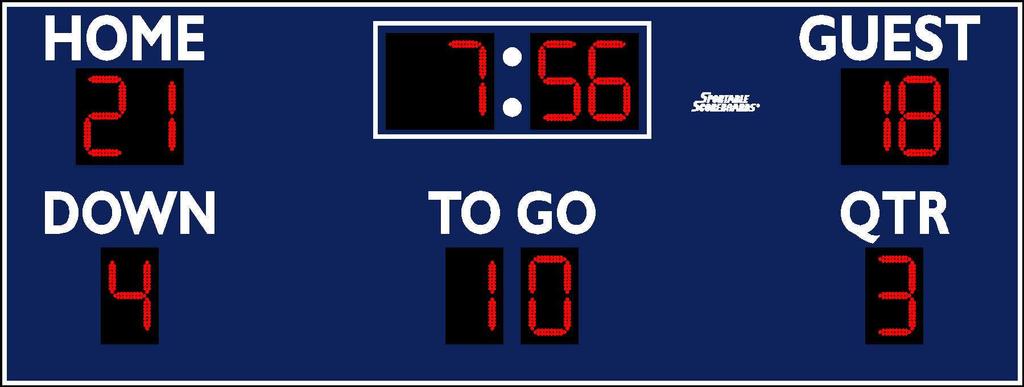
10 2. 3. The connections are standard black, white, and green (ground). Replace the cover when complete. TESTING THE INSTALLED SYSTEM NOTE: Please refer to the OPERATORS MANUAL on the CD, or included with the system to operate the scoreboard. Connecting cable-controlled systems: Connect one end of the supplied 20-ft. control cable into either of the two control cable jacks on the back of the controller and the other into the receptacle on the supplied junction box cover installed at the scorekeeper s location. Connecting wireless systems: Connect the wireless transmitter to the controller using the interface cable by plugging the large end of the interface cable into either of the control cable jacks on the back of the controller. Testing the scoreboard system in diagnostic mode: 1. Connect the appropriate end of the 12-volt DC wall transformer to the power receptacle on the back of the controller. Plug the transformer into a live, 120-volt outlet. If the optional battery pack was purchased with the keyboard, the transformer is also used to charge the battery. 2. Turn the power to the scoreboard ON using the power disconnect switch or circuit breaker. The HOME and GUEST displays should read 0, TO GO should read 10, QUARTER and DOWN should read 1, and the clock should display the default start-up time. 10
11 3. With the controller OFF, press and hold the OPTION key while turning the controller ON. The controller s LCD will briefly display the controller s software version. When the display changes and reads SELECT DIAG MODE <DIGIT TEST>, press ENTER. The LCD will now read SEGMENT TEST SEGMENTS OFF. NOTE: None of the scoreboards components should be lit at this time. If any components are lit, especially with a solid 8, check the crossover connections between cabinets. Ensure that the red stripes on the ribbon cables are matched where they are connected. 1. Pressing the UP arrow (located on the far right of the controller s keypad) will cycle the scoreboard into digit count mode and all displays on the scoreboard will count 0-9 repetitively. Pressing the UP arrow again will cycle to <ALL ON>, and all components should display an 8. At this time, take a look at the segments of each component for LEDs that are not lit. 2. To exit the diagnostic mode, press the RESET key twice. 3. If all components pass this test, the installation is complete. 4. NOTE: Always turn both the controller and the scoreboard OFF after each use. If the controller is turned OFF but the scoreboard remains ON, (or if the controller loses communication with the scoreboard), the scoreboard s STRIKE digit will begin to flash. This feature is intended to remind the user to turn power to the scoreboard OFF after each use. 11
12 IMPORTANT! Warranty Activation/Installation & Completion Sign Off Sheet NOTE: This sheet must be completely filled out and returned/faxed (270) to Scoreboard Service Company before your warranty can be activated. Your Serial Number Your Model Number Date Purchased Sales Agent Person Authorizing Purchase (title) Date Installation Completed Company or Person Responsible For Installation (address/phone number) This document confirms that the installation for the 6-ft.x 16-ft. Football Scoreboard has been completed. All structural, wiring, and power requirements have been met. This unit has been tested in scoring and diagnostic modes, ensuring the functionally of the unit. Scoring/timing equipment responsible party Installer So that we may better serve you, please have this information available in the event you need to call technical support. Customer Service:
MODEL 3312 LED
 INSTALLATION INSTRUCTIONS FOR MODEL 3312 LED www.sportablescoreboards.com 1 Table of Contents DISCRIPTION... 3 THE SCOREBOARD SYSTEM SHOULD INCLUDE THE FOLLOWING PARTS:... 3 INSTRUCTIONS FOR REPORTING
INSTALLATION INSTRUCTIONS FOR
 INSTALLATION INSTRUCTIONS FOR MODEL 3314 LED www.sportablescoreboards.com 1 Table of Contents DESCRIPTION... 3 THE SCOREBOARD SYSTEM SHOULD INCLUDE THE FOLLOWING PARTS:... 3 INSTRUCTIONS FOR REPORTING
SC-9
 OPERATING INSTRUCTIONS FOR SC-9 www.sportablescoreboards.com 1 Table of Contents INSTRUCTIONS FOR REPORTING SHIPPING DAMAGE... 3 GETTING STARTED... 6 CABLE SYSTEMS... 6 WIRELESS SYSTEMS... 6 SUPPLYING
OPERATING INSTRUCTIONS FOR MODEL ST-15 5-DIGIT SPORTS TIMER
 OPERATING INSTRUCTIONS FOR MODEL ST-15 5-DIGIT SPORTS TIMER Table of Contents OPERATING INSTRUCTIONS... 0 MODEL ST-15... 0 2- YEAR WARRANTY... 2 IMPORTANT!... 3 Warranty Activation/Installation & Completion
Basketball Shot Clock Set LX2180 Manual
 Basketball Shot Clock Set LX2180 Manual 72 Industrial Boulevard Wrightsville, GA 31096 Phone: (800) 445-7843 Fax: (800) 864-0212 www.electro-mech.com LX2180 Revision 5 February 8, 2013 Table of Contents
MODEL 9266 LITTLE LEAGUE BASEBALL SCOREBOARD. Instruction Manual
 UNITEC MANUFACTURING DIVISION MODEL 9266 LITTLE LEAGUE BASEBALL SCOREBOARD (WITH INNING BY INNING SCORING & PITCH COUNT) Instruction Manual Mailing Address: PO Box 260, Yorkville, NY 13495-0260 Plant Address:
MODEL 9360-SO SOCCER SCOREBOARD
 MODEL 9360-SO SOCCER SCOREBOARD Instruction Manual Address: 34 Main Street, Whitesboro, NY 13492 Phone: 315-736-3967 Toll Free: 800-383-6060 Fax: 315-736-4058 SCOREBOARDS TIMERS MESSAGE SIGNS VIDEO DISPLAYS
SCOREBOARD SPECIFICATIONS FOR
 SCOREBOARD SPECIFICATIONS FOR MODEL 3365-58 LED www.sportablescoreboards.com Sportable Scoreboard Inc. 106 Max Hurt Drive Murray, KY 42071 Phone: 800-323-7745 Fax: 270-759-4112 www.sportablescoreboards.com
Nevco Message Center Installation Manual Retain this manual in your permanent file. 08/27/ Rev. C
 Nevco Message Center Installation Manual Retain this manual in your permanent file. 08/27/2014 135-0144 Rev. C Table of Contents INSTALLATION INSTRUCTIONS... 1 UNPACKING THE EQUIPMENT... 1 MESSAGE CENTER
EVERSAN. Instruction Manual MODEL 9007/9008 TENNIS SCOREBOARD. Address: 34 Main Street, Whitesboro, NY 13492
 MODEL 9007/9008 TENNIS SCOREBOARD Instruction Manual Address: 34 Main Street, Whitesboro, NY 13492 Phone: 315-736-3967 Toll Free: 800-383-6060 Fax: 315-736-4058 SCOREBOARDS TIMERS MESSAGE SIGNS VIDEO DISPLAYS
ELECTRO-MECH SCOREBOARD CO.
 ELECTRO-MECH SCOREBOARD CO. MODEL 2570 BASKETBALL SCOREBOARD OWNER S HANDBOOK Thank you for choosing an Electro-Mech Scoreboard for your athletic complex. We are confident that your new scoreboard will
ELECTRO-MECH SCOREBOARD CO.
 ELECTRO-MECH SCOREBOARD CO. MODEL 2350 BASKETBALL SCOREBOARD OWNER S HANDBOOK Thank you for choosing an Electro-Mech Scoreboard for your athletic complex. We are confident that your new scoreboard will
ELECTRO-MECH SCOREBOARD CO.
 ELECTRO-MECH SCOREBOARD CO. MODEL 2150 SHOT TIMER OWNER S HANDBOOK Thank you for choosing an Electro-Mech Scoreboard for your athletic complex. We are confident that your new shot timer will give many
Operating Instructions & Service Manual FOULS
 FOULS Operating Instructions & Service Manual FOULS Basketball Player Fouls Panels Model MP-5215 EFFECTIVE S.N. 17,100, June 18, 2001 TABLE OF CONTENTS PAGE 1. GENERAL INFORMATION 3 1.1 DESCRIPTION 1.2
ELECTRO-MECH SCOREBOARD CO.
 ELECTRO-MECH SCOREBOARD CO. MP-320 DELAY OF GAME TIMER SCOREBOARD OWNER S HANDBOOK Thank you for choosing an Electro-Mech Scoreboard for your athletic complex. We are confident that your new scoreboard
ELECTRO-MECH SCOREBOARD CO.
 ELECTRO-MECH SCOREBOARD CO. MODEL 8850 HOCKEY SCOREBOARD OWNER S HANDBOOK Thank you for choosing an Electro-Mech Scoreboard for your athletic complex. We are confident that your new scoreboard will give
ELECTRO-MECH SCOREBOARD CO.
 ELECTRO-MECH SCOREBOARD CO. 3050 FOOTBALL DELAY OF GAME TIMER OWNER S HANDBOOK Thank you for choosing an Electro-Mech Scoreboard Company product for your athletic complex. We are confident that it will
EVERSAN. MODEL 9658 EVERSAN PERIOD INDOOR/OUTDOOR MULTI-FUNCTION SCOREBOARD. Instruction Manual
 MODEL 9658 EVERSAN HOME PERIOD POSS. POSS. BONUS BONUS GUEST INDOOR/OUTDOOR MULTI-FUNCTION SCOREBOARD Instruction Manual Address: 34 Main Street, Whitesboro, NY 13492 Phone: 315-736-3967 Toll Free: 800-383-6060
OPERATING INSTRUCTIONS AND SERVICE MANUAL BASKETBALL SHOTCLOCK MODEL MP-5299
 OPERATING INSTRUCTIONS AND SERVICE MANUAL BASKETBALL SHOTCLOCK MODEL MP-5299 EFFECTIVE S.N. 17,000, December, 2000 TABLE OF CONTENTS 1. General Information 1.1 Description 1.2 Identification 1.3 Damage
OPERATING INSTRUCTIONS AND SERVICE MANUAL. MODEL MP-3804 BLACK FLAG DISPLAY WITH MP-2002 Control
 OPERATING INSTRUCTIONS AND SERVICE MANUAL MODEL MP-3804 BLACK FLAG DISPLAY WITH MP-2002 Control EFFECTIVE S.N. 18,959 May 2, 2003 TABLE OF CONTENTS 1. General Information 1.1 Description 1.2 Identification
SECTION MODEL 2577 INDOOR SCOREBOARD. A. Single-face electronic scoreboard and control console for indoor use.
 SECTION 116643 MODEL 2577 INDOOR SCOREBOARD PART 1 GENERAL 1.01 SECTION INCLUDES A. Single-face electronic scoreboard and control console for indoor use. 1.02 REFERENCES A. Standard for Electric Signs,
ELECTRO-MECH SCOREBOARD CO.
 ELECTRO-MECH SCOREBOARD CO. MP-259/220, MP-259/220V, MP-259/220W, MP-269/220, MP-269/220V, MP-269/220W BASKETBALL SCOREBOARDS OWNER S HANDBOOK Thank you for choosing an Electro-Mech Scoreboard for your
Model LX2550 Product Guide
 Model LX2550 Product Guide Indoor Basketball Scoreboard 72 Industrial Boulevard Wrightsville, GA 31021 Phone:(800) 445-7843 Fax:(800) 864-2012 www.electro-mech.com LX2550 Revision 7 October 21, 2012 Table
Model LX2370 Product Guide
 Model LX2370 Product Guide Indoor Basketball Scoreboard 72 Industrial Boulevard Wrightsville, GA 302 Phone:(800) 445-7843 Fax:(800) 864-202 www.electro-mech.com Table of Contents Scoreboard Specifications...3
Model LX8850 Product Guide
 Model LX8850 Product Guide Indoor Hockey Scoreboard 72 Industrial Boulevard Wrightsville, GA 31021 Phone:(800) 445-7843 Fax:(800) 864-2012 www.electro-mech.com LX8850 Revision 7 February 27, 2013 Table
OPERATING INSTRUCTIONS AND SERVICE MANUAL 4000 SCOREBOARD CONVERSION. TO PLAY WITH 5000 SCOREBOARD and CONTROL
 OPERATING INSTRUCTIONS AND SERVICE MANUAL 4000 SCOREBOARD CONVERSION TO PLAY WITH 5000 SCOREBOARD and CONTROL EFFECTIVE S.N. 17,500, November 28, 2001 TABLE OF CONTENTS 1. GENERAL INFORMATION 1.1 DESCRIPTION
SECTION MODEL INDOOR SCOREBOARD. A. Four-face electronic scoreboard and control console for indoor use.
 SECTION 116643 MODEL 2650-4 INDOOR SCOREBOARD PART 1 GENERAL 1.01 SECTION INCLUDES A. Four-face electronic scoreboard and control console for indoor use. 1.02 REFERENCES A. Standard for Electric Signs,
Model LX8750 Product Guide
 Model LX8750 Product Guide Indoor Hockey Scoreboard 72 Industrial Boulevard Wrightsville, GA 31021 Phone:(800) 445-7843 Fax:(800) 864-2012 www.electro-mech.com LX8750 Revision 7 October 22, 2012 Table
OPERATING INSTRUCTIONS AND SERVICE MANUAL FOOTBALL SCOREBOARD MODEL MP-7442 WITH MP-5000 CONTROL
 OPERATING INSTRUCTIONS AND SERVICE MANUAL FOOTBALL SCOREBOARD MODEL MP-7442 WITH MP-5000 CONTROL EFFECTIVE S.N. 18,725, June, 2005 TABLE OF CONTENTS 1. General Information 1.1 Description 1.2 Identification
Nevco Outdoor LED Scoreboard Installation Manual
 Nevco Outdoor LED Scoreboard Installation Manual Retain this manual in your permanent file. //5 5-0RA Section : Installation Instructions Installation consists of three steps (Unpacking the Equipment,
OPERATING INSTRUCTIONS AND SERVICE MANUAL OUTDOOR HOCKEY SCOREBOARD MODEL MP-3555 WITH MP-3000 CONTROL MODEL
 OPERATING INSTRUCTIONS AND SERVICE MANUAL OUTDOOR HOCKEY SCOREBOARD MODEL MP-3555 WITH MP-3000 CONTROL MODEL EFFECTIVE S.N.XXXX, DEC 20, 1999 1. General Information TABLE OF CONTENTS 1.1 Description 1.2
OPERATING INSTRUCTIONS AND SERVICE MANUAL BASEBALL SCOREBOARD MODEL MP-3350 WITH MP-2002 CONTROL
 OPERATING INSTRUCTIONS AND SERVICE MANUAL BASEBALL SCOREBOARD MODEL MP-3350 WITH MP-2002 CONTROL EFFECTIVE S.N. XXXX JAN 1, 1993 1 1. General Information TABLE OF CONTENTS 1.1 Description 1.2 Identification
OPERATING INSTRUCTIONS AND SERVICE MANUAL BASEBALL SCOREBOARD MODEL MP-7388 WITH MP-5000 CONTROL
 OPERATING INSTRUCTIONS AND SERVICE MANUAL BASEBALL SCOREBOARD MODEL MP-7388 WITH MP-5000 CONTROL EFFECTIVE S.N.18,725, July, 2004 TABLE OF CONTENTS 1. General Information 1.1 Description 1.2 Identification
INSTRUCTION MANUAL DIGI-LOCK. Keyless Entry System. Installation. Programming. Troubleshooting. BASE Industries
 INSTRUCTION MANUAL DIGI-LOCK Keyless Entry System Installation Programming Troubleshooting BASE Industries 45 Pomona Rd. Corona, CA. 9880 Revision F TABLE OF CONTENTS OWNER REGISTRATION CARD INTRODUCTION
TECHKNOW, INC. Kiosk Order Confirmation System INSTALLATION MANUAL. Revision Date: July 11, 2012 Part # Version 3.2
 document Page 1 of 18 TECHKNOW, INC Kiosk Order Confirmation System INSTALLATION MANUAL Revision Date: July 11, 2012 Part # Version 3.2 Techknow, Inc. 393 Mayfield Road Duncan, SC 29334 www.gotechknow.com
INDOOR SPORTS SCOREBOARD INSTALLATION RECOMMENDATIONS REV
 INDOOR SPORTS SCOREBOARD INSTALLATION RECOMMENDATIONS 98-0001-23 REV 1805.03 TABLE OF CONTENTS DISCLAIMER The suggestions and recommendation within this document are intended as a guide for the installation
VRp Three-Phase Precision AC Voltage Regulator
 VRp-22500-0338 Three-Phase Precision AC Voltage Regulator INSTALLATION INSTRUCTIONS Inspection and Unpacking Please inspect the wooden crate for obvious shipping damage. Some crates contain up to six (6)
Model LX2655 Product Guide
 Model LX2655 Product Guide Indoor Scoreboard for Basketball/Volleyball/Wrestling 72 Industrial Boulevard Wrightsville, GA 31021 Phone:(800) 445-7843 Fax:(800) 864-2012 www.electro-mech.com LX2655 Revision
EVERSAN. MODEL 9769 BASKETBALL, VOLLEYBALL, WRESTLING SCOREBOARD. Instruction Manual
 MODEL 9769 BASKETBALL, VOLLEYBALL, WRESTLING SCOREBOARD Instruction Manual Address: 34 Main Street, Whitesboro, NY 13492 Phone: 315-736-3967 Toll Free: 800-383-6060 Fax: 315-736-4058 SCOREBOARDS TIMERS
MODEL 9386 MULTI-SPORT TIMER
 MODEL 9386 MULTI-SPORT TIMER Instruction Manual Address: 34 Main Street, Whitesboro, NY 13492 Phone: 315-736-3967 Toll Free: 800-383-6060 Fax: 315-736-4058 SCOREBOARDS TIMERS MESSAGE SIGNS VIDEO DISPLAYS
ControlKeeper 4. General Information. Connecting Relay Loads. Installation Sheet. Getting Started. Power Supply Wiring. Mounting the Cabinet
 General Information ControlKeeper 4 Installation Sheet Model# CK4-120NO- Model# CK4-277NO The ControlKeeper-4 model is shipped in one package and is configured with either a 120V or a 277V transformer.
OPERATING INSTRUCTIONS AND SERVICE MANUAL HOCKEY SCOREBOARD. MODEL MP-3579 WITH MP-3000 Control
 OPERATING INSTRUCTIONS AND SERVICE MANUAL HOCKEY SCOREBOARD MODEL MP-3579 WITH MP-3000 Control EFFECTIVE S.N. 11370 MARCH 7,1996 TABLE OF CONTENTS 1. General Information 1.1 Description 1.2 Identification
ReachFree ID Installation Instructions for Wash Select II. Unitec
 ReachFree ID Installation Instructions for Wash Select II Unitec www.startwithunitec.com Proprietary Information and Materials of Unitec Inc. Such proprietary information and materials may not be disclosed
It s a Better Way to Weigh!
 Midmark Way Platform Scale It s a Better Way to Weigh! Table of Contents Pre-Installation......................... 2 Specifications... 2 Parts Identification... 3 Assembly & Installation... 3-4 Post Mounted
SPECIAL INSTRUCTIONS FOR CAPACITORS COMPACT GENERATORS
 SPECIAL INSTRUCTIONS FOR CAPACITORS COMPACT GENERATORS (WITH CAPACITOR CHARGER BOARD A3517-02) The process depends on Generator and System configuration. This document applies to installation of Capacitors
Installation & Operations Manual
 Installation & Operations Manual Emergency Solar Tower Phone 2100-TSL Landline Solar Tower 2100-TSC Cellular Solar Tower 2100-TS9 900 MHz Solar Tower 2100-TST 2-Way Radio Solar Tower 2100-TSV VoIP Solar
Installation/Operating Instructions 220V VCB Silhouette/Series E Electric Video Conferencing Background by Draper
 Installation/Operating Instructions 220V VCB Silhouette/Series E Electric Video Conferencing Background by Draper Caution 1 Read instructions through completely before proceeding; keep them for future
Instruction Manual. Electrical Management System (EMS) EMS-HW30C & EMS-HW50C
 EMS-HW30C & EMS-HW50C") Instruction Manual Electrical Management System (EMS) EMS-HW30C & EMS-HW50C EMS-HW50C EMS-HW30C! CAUTION These instructions are intended to provide assistance with the installation of this product, and
Instruction Manual Electrical Management System (EMS) EMS-HW30C & EMS-HW50C EMS-HW50C EMS-HW30C! CAUTION These instructions are intended to provide assistance with the installation of this product, and
Nevco Indoor LED Scoreboard Installation Manual
 Nevco Indoor LED Scoreboard Installation Manual Retain this manual in your permanent file. Rev. 8/6/09 135-014 Installation Instructions Installation consists of three steps, Unpacking the Equipment, Scoreboard
Blackout Shutter Kits with Breathable Wall Light Traps
 Blackout Shutter Kits with Breathable Wall Light Traps 2018 Growers Supply All Rights Reserved. Reproduction is prohibited without permission. Revision date: 05.10.18 Maintain controlled airflow without
Secured Series: Hub Plus Kit Single Door Controller Package Installation Manual
 Secured Series: Hub Plus Kit Single Door Controller Package Installation Manual This package is designed to simplify the connections to our Secured Series Hub Plus Controller. This will translate into
DVI KVM. Extra Long Range Extender Over One CAT5. User Manual EXT-DVIKVM-ELR. Release A8
 DVI KVM Extra Long Range Extender Over One CAT5 EXT-DVIKVM-ELR User Manual Release A8 Important Safety Instructions 1 Read these instructions 2 Keep these instructions 3 Heed all warnings 4 Follow all
CONSOLE CONNECTOR KIT 9501 INSTALLATION INSTRUCTIONS
 CONSOLE CONNECTOR KIT 9501 INSTALLATION INSTRUCTIONS FOR USE WITH: HAMMOND Organ Models L-100, M-100 Series, M-l, M-2, M-3 LESLIE Speaker Models 760, 770, 825 KIT CONTENT Console Connector Assembly 043075
Blackout Shutter Kits with Breathable Wall Light Traps
 Blackout Shutter Kits with Breathable Wall Light Traps 2018 Growers Supply All Rights Reserved. Reproduction is prohibited without permission. Maintain controlled airflow without sacrificing blackout environments.
Quick Start Installation Guide
 apc/l Quick Start Installation Guide Version A2 Document Part Number UM-201 May 2010 OVERVIEW The apc/l is an intelligent access control and alarm monitoring control panel which serves as a basic building
Preparing for a Docking Drawer Slim Installation To prepare for a successful Docking Drawer Slim installation please ensure that the cable management
 Docking Drawer Install Manual Docking Drawer Slim Series Applicable Models: 0290 00031(W) / 24 0290-00030(W) / 21 0290-00047(W) / 18 0230-00004. r6 1/19/2016 CAUTION READ CAREFULLY Failure to follow these
1. Carefully unpack the um260 s shipping carton and check the contents for damage.
 um260 Installation Manual um260 Installation Chapter 4 um260 MICRO MONITOR INSTALLATION This section of the um260 Micro Monitor Installation Manual describes the requirements and procedures for installing
ICS Entrance Management Sign Installation Guide. Version 1.0
 ICS Entrance Management Sign Installation Guide Version 1.0 Thank you for purchasing your new ICS Entrance Management System (EMS) from Innovative Control Systems, Inc. Installation Overview This document
Validator Update Instructions for Rowe BC1200 $1 - $20
 Validator Update Instructions for Rowe BC1200 $1 - $20 Kit Overview The purpose of the kit is to replace the Rowe BA50 transport and stacker with a 120 volt Mars validator with a compact mask. The kit
Specifications for Modular Sound Shadow Sound Masking Sound Management Group, LLC.
 Specifications for Modular Sound Shadow Sound Masking Sound Management Group, LLC. 1.01 General Requirements This section details general requirements for plenum sound masking installations. 1.1 Contract
FDS / FDS-R / FDS-PS
 FDS / FDS-R / FDS-PS USER MANUAL For use with 120V 60Hz input. Output is 120V 60Hz at 5amps 600W MAX. switched. ETL LISTED Conforms to UL STD 1241 3091594 79-15167-00 REV. A www.fiberstars.com Page 1 of
Model# CKM18 Model# CKM36 Model# CKM48 WARNING
 Installation Instructions Model# CKM18 Model# CKM36 Model# CKM48 WARNING HAZARDOUS VOLTAGES. DISCONNECT FROM SUPPLY BEFORE REMOVING COVERS. NO USER SERVICEABLE PARTS INSIDE. SERVICE BY QUALIFIED PERSONNEL
Copy Machine Reader. Installation and Setup Guide
 Copy Machine Reader Installation and Setup Guide CONTENTS 1 COPY MACHINE READER INSTALLATION 1 Overview 1 Reader Specifications 3 CR1120/CR1122 INSTALLATION 3 Copier Interface 3 AC Electrical 3 Communications
Breaker Panel Technical Practice NPDRP1114
 030-000218 REV E 1114-03E January 30, 2013 Westell Breaker Panel Technical Practice NPDRP1114 FEATURES DIN rail panel accepts up to 6 DIN rail devices (one surge and 5 breakers) Specific configuration
Electrical Management System (EMS) EMS-HW30C & EMS-HW50C
 EMS-HW30C & EMS-HW50C") Electrical Management System (EMS) EMS-HW30C & EMS-HW50C Installation & Operating Guide for: Model EMS-HW30C Rated at 120V/30A and Model EMS-HW50C Rated at 240V/50A Surgio Says Lifetime Warranty on all
Electrical Management System (EMS) EMS-HW30C & EMS-HW50C Installation & Operating Guide for: Model EMS-HW30C Rated at 120V/30A and Model EMS-HW50C Rated at 240V/50A Surgio Says Lifetime Warranty on all
M215-Z Safety Information (M LL-IG-ZC)
") M215-Z SAFETY M215-Z Safety Information (M215-60-2LL-IG-ZC) This document contains important instructions to use during installation of the M215-Z Zep Compatible Microinverters. To reduce the risk of electrical
M215-Z SAFETY M215-Z Safety Information (M215-60-2LL-IG-ZC) This document contains important instructions to use during installation of the M215-Z Zep Compatible Microinverters. To reduce the risk of electrical
CP150B Vandal & Weather Resistant Keypad Security Systems
 Vandal & Weather Resistant Keypad Security Systems EN Security System CP150B - Vandal & Weather Resistant Keypad The CP150B keypad provides alarm and or access control functionality when used on selected
HIGH-5 INSTALLATION INSTRUCTIONS /460V Three-Phase Input using ABB ACS355 VFD
 HIGH-5 INSTALLATION INSTRUCTIONS 208-230/460V Three-Phase Input using ABB ACS355 VFD For an electronic copy of these instructions, please visit www./installation-services-and-guides TABLE OF CONTENTS Safety
Click Save to return to the main Setup screen.
 ON-SITE Setup Guide Thank you for purchasing the ON-SITE. This guide will assist you in the setup of the system. You can call for FREE technical support to get help anytime at 757-258-0910. Please note,
CAUTION READ CAREFULLY
 Docking Drawer Install Manual for DD 21 + 24 Slim Applicable Models: 0290-00030, 0290-00030W, 0290 00031, 0290 00031W 0230-00004. r5 10/21/2015 CAUTION READ CAREFULLY Failure to follow these instructions
Site Preparation CHAPTER
 CHAPTER 3 Site Preparation This chapter describes the steps to take and the considerations you should keep in mind prior to installing the modules in an open rack. It also contains information that applies
User s Manual. ACS550-PD 3R Irrigation Packaged Drive Supplement to ACS550-U1 User s Manual
 User s Manual ACS550-PD 3R Irrigation Packaged Drive Supplement to ACS550-U1 User s Manual 2 ACS550-PD 3R Irrigation Packaged Drive ACS550 Drive Manuals GENERAL MANUALS ACS550-U1 User s Manual (1 200 HP)
Assembly and Setup Manual
 M-11 Series Copyboard/C-11 Series Captureboard Assembly and Setup Manual This is the installation and assembly manual for the M-11 series/c-11 series. To the Customer Specialized techniques are required
Instruction / Installation Sheet DataComm Electronics WH Recessed Pro-Power Kit with Duplex Receptacle and Straight Blade Inlet
 Instruction / Installation Sheet DataComm Electronics 45-0024-WH Recessed Pro-Power Kit with Duplex Receptacle and Straight Blade Inlet DataComm Electronics, Inc. 6349 Peachtree Street Norcross, GA 30071-1725
M215 Safety (M LL-S22-IG / S23-IG / S24-IG)
") M215 SAFETY M215 Safety (M215-60-2LL-S22-IG / S23-IG / S24-IG) Important Safety Information This document contains important instructions to use during installation of the Enphase M215 Microinverter. To
M215 SAFETY M215 Safety (M215-60-2LL-S22-IG / S23-IG / S24-IG) Important Safety Information This document contains important instructions to use during installation of the Enphase M215 Microinverter. To
A Axis M-Functions Level 1 A Axis Standard A Axis SMT Level 2. Each console includes the following:
 Hardware List The 3000M Crusader II Upgrade system has been custom configured to provide the necessary hardware required for installation on your machine. Verify that you have received all the correct
QUASAR Installation & Maintenance Guide motorized actuator for windows and skylights
 Functional Fenestration Inc (FFI) Quasar Actuator Application Options On Wall or Frame Awning Skylight Hopper Concealed in Frame or Curtain Wall CAD files available on request from FFI. Optional brackets
FIT. Fuel Island Terminal Installation and Operation Manual. The material in this manual is subject to engineering changes and editorial revisions
 FIT Fuel Island Terminal Installation and Operation Manual The material in this manual is subject to engineering changes and editorial revisions Copyright 2002 OPW Fuel Management Systems OPW Fuel Management
ALTAI C1N SUPER WIFI CPE INSTALLATION GUIDE. Version 1.0 Date: September, Altai Technologies Ltd. All rights reserved
 ALTAI C1N SUPER WIFI CPE INSTALLATION GUIDE Version 1.0 Date: September, 2013 Copyright 2007 Altai Technologies Limited ALL RIGHTS RESERVED. Altai Technologies Limited Unit 209, 2/F, East Wing, Building
Westell. Breaker Panel Technical Practice NPDRP1114
 030-000218 REV F 1114-03F June 29, 2017 Westell Breaker Panel Technical Practice NPDRP1114 FEATURES DIN rail panel accepts up to 6 DIN rail devices (one surge and 5 breakers) Specific configuration of
DC Outdoor Power Supply/Chargers
 DC Outdoor Power Supply/Chargers Installation Guide Models Include: WayPoint3 WayPoint7-2.5A @ 12VDC or 24VDC. - 6A @ 12VDC or 24VDC. - 115/230VAC input. - 115VAC input. WayPoint5 WayPoint7V - 4A @ 12VDC
Owner s Manual. Models 1503 and 1504 Basic Stand Alone Digital Keypad Entry Devices
 Owner s Manual Models 1503 and 1504 Basic Stand Alone Digital Keypad Entry Devices DoorKing, Inc. 120 Glasgow Avenue Inglewood, California 90301 U.S.A. Phone: 310-645-0023 Fax: 310-641-1586 www.doorking.com
FLEXBOX. Installation Guide
 FLEXBOX Installation Guide FLEXBOX 1 Important Safety Instructions WEIGHT LIMIT MAXIMUM WEIGHT 50 LBS. THE STRUCTURE TO WHICH THE BOX IS MOUNTED (CEIL- ING, WALL, TABLE, POLE) MUST BE ABLE TO SUPPORT FIVE
Revision History E F G H J K Revision Description: K > Allegion Rebranding.
 Notes: Enter any notes here. These notes must include: how many sides of the paper are printed ink color (usually black, may also be one or two specific colors, such as a Pantone value, or 17.000 8.500
Installation, Testing, and Operating Procedures 30 AMP PORTABLE AND PERMANENT SERIES GFCI SINGLE and MULTIPHASE
 IMPORTANT! Please read all the information on this sheet. SAVE THESE INSTRUCTIONS! NOTICE BEFORE USING READ INSTRUCTIONS COMPLETELY. TO BE INSTALLED BY A QUALIFIED ELECTRICIAN IN ACCORDANCE WITH NATIONAL
SPECIAL PROJECTS 3800 Hwy 271 North Powderly, TX Phone: Fax: Aqua 20/20 OWNER S MANUAL
 SPECIAL PROJECTS 3800 Hwy 271 North Powderly, TX 75473 Phone: 866-491-2677 Fax: 866-746-4366 Aqua 20/20 OWNER S MANUAL AQUA 808 Beltpack Transmitter Power Indication Low Battery Indicator Power Button
FEATURES. AlphaBlueLight Emergency Towers Installation & Operations Manual FIGURE 1: FRONT & REAR VIEWS
 AlphaBlueLight Emergency Towers Installation & Operations Manual FIGURE 1: FRONT & REAR VIEWS FEATURES ADA Compliant (hands free operation) LED call status indicator Powder coated steel construction inside
Installation Instructions. (220V Single-phase Input using ABB ACS550 VFD)
") Installation Instructions (220V Single-phase Input using ABB ACS550 VFD) 1 TABLE OF CONTENTS Parts List.... Page 3 Fan Placement, Spacing, and Clearance..... Page 4 Fan Maintenance.. Page 4 Installation
Installation Instructions (220V Single-phase Input using ABB ACS550 VFD) 1 TABLE OF CONTENTS Parts List.... Page 3 Fan Placement, Spacing, and Clearance..... Page 4 Fan Maintenance.. Page 4 Installation
hp uninterruptible power system r12000 xr models installation instructions
 hp uninterruptible power system r000 xr models installation instructions Overview These instructions show how to install an uninterruptible power system (UPS). For detailed information about the UPS, refer
Table of Contents. Unpacking and Inspection Setup Loading the Media Mount the Printer on the Wall... 16
 WPL25/WHC25 Table of Contents Unpacking and Inspection... 1 Setup... 5 Loading the Media... 6 Mount the Printer on the Wall... 16 LED and Button Functions... 17 Troubleshooting... 18 Unpacking and Inspection
Power Supply (48Vdc, 2.5A)
") Telecommunications Group Section 855-180-201 Equipment Issue 1 Fourth Printing, September 2006 8551-80 Power Supply (48Vdc, 2.5A) Compliant with UL Standard 60950, Second Edition* CONTENTS PAGE Part 1.
Telecommunications Group Section 855-180-201 Equipment Issue 1 Fourth Printing, September 2006 8551-80 Power Supply (48Vdc, 2.5A) Compliant with UL Standard 60950, Second Edition* CONTENTS PAGE Part 1.
Arca LED 5YEAR LED WARRANTY. Order Code: Pole Order Code: Customer: Date: Project: Qty: Type: ACL ACL. R2 Type II Distribution.
 Date: Customer: Project: Type: Qty: Arca LED Order Code: Pole Order Code: ACL - R2 - - - - - - - - - HC - - - - - - - - - Series Height Finish Helicoil Options *Helicoil Locations Pair * Refer to chart
InView Marquee Message Display
 Installation Instructions InView Marquee Message Display Introduction These instructions show how to change the serial address and how to mount InView series signs with NEMA Types 4, 4X, and 12 enclosures.
User Manual. EventCUBE CW/WW
 User Manual EventCUBE CW/WW Introduction: Thank you for your purchase. The EventCUBE CW/WW is a DMX intelligent LED Pin Spot light. This LED Pin Spot light is for the serious production company looking
Premises Pager System Glowster Pagers
 Pager and Charger Guide Part Number 321035A5 Premises Pager System Glowster Pagers Chargers Components Introduction Introduction: Congratulations on your purchase of a JTECH Paging System. Please take
Back-UPS RS APC Back-UPS RS 800VA 120V Black
 Back-UPS RS APC Back-UPS RS 800VA 120V Black APC Back-UPS RS, 540 Watts / 800 VA,Input 120V / Output 120V Includes: CD with software, Cord management straps, Free trial of anti-virus : firewall : email
CC186 AND CC186/2 STAND-ALONE OR SYSTEM CLOCK
 FN:CC186M2.DOC CC186 AND CC186/2 STAND-ALONE OR SYSTEM CLOCK DESCRIPTION The CC186 is a single sided clock with six, 1.8 inch high digits. The CC186/2 is a double sided clock with six, 1.8 inch high digits
60W Power over Ethernet Waterproof Adapter PoE IEEE BT Single Port Injector for Outdoor Application
 WWW.PHIHONG.COM 60W Power over Ethernet Waterproof Adapter PoE IEEE BT Single Port Injector for Outdoor Application Features Compliant with the IEEE802.3bt Standard Non-Vented Case with Mounting Bracket
PS8 - II. Professional Power Sequencer. User s Manual
 PS8 - II Professional Power Sequencer User s Manual IMPORTANT SAFETY INSTRUCTIONS READ FIRST This symbol, whenever it appears, alerts you to the presence of uninsulated dangerous voltage inside the enclosure.
MC-1 OPERATION MANUAL MINI CAMERA JW FISHERS MFG INC 1953 COUNTY ST. E. TAUNTON, MA USA
 MC-1 MINI CAMERA OPERATION MANUAL JW FISHERS MFG INC 1953 COUNTY ST. E. TAUNTON, MA 02718 USA (508) 822-7330; (800) 822-4744; FAX (508) 880-8949 Email: info@jwfishers.com WEB: www.jwfishers.com SPECIFICATIONS