SPID Elektronik. Driver MD-02 MD-02
|
|
|
- Theresa Lynch
- 5 years ago
- Views:
Transcription


1 SPID Elektronik Driver MD-02 MD-02
2 Table of contents Table of contents... 2 Introduction... 4 Block diagram... 4 Parameters of the driver... 4 Photos and description... 5 Front... 5 Back... 5 Operation... 7 Normal mode (NORMAL)... 7 Calibration mode (MOTOR ANGLES)... 8 Driver MD-02 configuration... 8 Motor configuration... 8 TEMPLATE... 8 Start... 9 Stop... 9 External control (CONTROL xx)... 9 Protocol (PROT. xx) Set motors (SET MOTOR 1, SET MOTOR 2) STATE TYPE KIND INPUT GEAR MIN ANGLE MAX ANGLE MAX POWER... 11
3 START POWER, START TIME STOP POWER, STOP TIME STOP AT PULS TIMEOUT SET COM 0, SET COM STATE BAUD DATA BITS STOP BITS PARITY SET USB COM STATE BAUD DATA BITS STOP BITS PARITY SET ETHERNET STATE... 13
 or double (one Azimuth / Elevation rotor). The basic circuit provides operation with direct current motors.")
4 Introduction MD-02 is an electronic driver used for turning rotors. It is a multifunctional device, allowing for various combinations of work setting. The driver may be connected to two single rotors (e.g. two Azimuth rotors) or double (one Azimuth / Elevation rotor). The basic circuit provides operation with direct current motors. Block diagram Parameters of the driver supply voltage of driver MD VDC (I max 2A), supply voltage of rotors VDC (I max 40 A), the maximum current of a single motor up to 20 A. 2 x RS232 ports 1 x USB host port 1 x USB device visible in the system as the virtual COM port. 1 x Ethernet RJ45 port.
. 6. Supply outputs for Rotor BIG-RAS Elevation.")
, PINs in the driver (1, 2). Every output has its own FUZE (20A). 8. Switch used to update the driver software (FIRMWARE).")
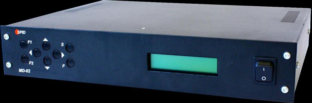
5 Photos and description Front 1. Keyboard. 2. 2x20 characters display. 3. Switch-key. Back 1. Plug-in socket to turn on Ground (the remaining NC PINs). 2. Rotor motor supply input (FUZE 40A). 3. NC, in the future planned for connecting modules, e.g. CAN, RS485, RS422 or analogue inputs. 4. Inching input for systems with two sensors type HALL. 5. Electronics supply input (FUZE 2A). 6. Supply outputs for Rotor BIG-RAS Elevation. PINs for motor supply. Elevation PINs from the motor (3,4), PINs in the driver (1, 2). Every output has its own FUZE (20A). 7. Supply outputs for Rotor BIG-RAS Elevation. PINs for motor supply. Elevation PINs from the motor (1,2), PINs in the driver (1, 2). Every output has its own FUZE (20A). 8. Switch used to update the driver software (FIRMWARE). To update the software we use COMO (item 12), while we turn the switch OFF. Normal mode of the driver is when the switch is in the PR position. 9. Universal output the possibility to connect inside the module driver with relays. Then the controller will have the function of antenna change-over switch. 10. I2C output used to control SW-01 switch. 11. USB HOST port (type A plug) and DEVICE port (type B plug). 12. RS232 ports COM0 and COM1. COM0 is also used to update the driver software (see item 8). 13. Input used to control a specially designed mouse. 14. Network input RJ45 (ETHERNET).

6 Descriptions of PINs of sockets in the back panel
 In this mode the driver may be operated with the [Right], [Left], [Up] and [Down] buttons or receives the command from PC.")
7 Operation MD-02 Driver may be operated with the use of a keyboard or a computer. MD-02 module has two modes (MODE). NORMAL normal mode. MOTOR ANGLES calibration mode. To change the mode, use the [F] key. Normal mode (NORMAL) In this mode the driver may be operated with the [Right], [Left], [Up] and [Down] buttons or receives the command from PC. The driver supports communications protocols such as SPID ROT1, SPID ROT2, SPID MD02, BRITE, YAESU and HyGain, which you can attribute to each communications port (COM0, COM1, USB D and ETH) in the settings. The [Right] and [Left] buttons are used to rotate the antennae in the azimuth. The right direction the antennae turns in a clockwise direction, the value of the angle in the display increases. The left direction the antennae turns in an anticlockwise direction, the value of the angle in the display decreases. The [Up] and [Down] buttons are used to rotate the antennae in the angle of elevation. The up direction the rotor turns right from the point of view of the front. The value of the angle in the display increases. The down direction the rotor turns left from the point of view of the front. The value of the angle in the display decreases. The directions of antennae rotation are shown in the picture:
8 Calibration mode (MOTOR ANGLES) To switch-over the driver in the calibration mode use the button [F]. In this mode you can set any value of the angle in the azimuth and in the elevation angle without turning the antennae. This mode is needed to preliminary calibrate the antennae. To set the azimuth angle to zero, push the [F1] and [Left] buttons simultaneously. In order to set the elevation angle to zero, push the [F1] and [Up] buttons simultaneously. To set any azimuth angle use the buttons [Left] and [Right], while to change the elevation angle use the buttons [Up] and [Down]. After setting any azimuth angle use the buttons [Left] and [Right], while to change the elevation angle push the buttons [Up] and [Down]. After completing the calibration you need to leave the calibration mode and come back to the normal mode by pushing the [F] button. Driver MD-02 configuration When driver MD-02 is in NORMAL mode you can use button [S] to enter configuration. The structure of driver configuration is modular. Select module using buttons [Left] or [Right]. When you select module you can use button [S] to enter in its parameters. Moving between parameters is done with buttons [Left] or [Right]. Value of parameter can change with buttons [Up] or [Down]. Button [F] is used for exiting configuration. After pushing button there is question about writing current configuration. If we want to confirm changes we are pressing button [Left], if we want to go back to previous configuration we are pressing [Right]. Motor configuration The number before the ":" in the name of the template determines which connector on the rear panel must be connected motor: 1. AZIMUTH 2. ELEVATION TEMPLATE Type of motors connected to the controller is pre-set by templates: 1:NC, 2:NC - no motors connected to the controller, 1:AZ, 2:NC - a motor is connected on the rear panel of controller on connector AZIMUTH. Motor rotates only in azimuth, 1:NC, 2:EL - a motor is connected on the rear panel of controller on connector ELEVATION. Motor rotates only in elevation, 1:AZ, 2:EL - there are two motors connected to the controller. Motor 1 (connector AZIMUTH) rotates in azimuth, and Motor 2 (connector ELEVATION) - rotates in elevation,
9 1:AZ, 2:AZ - there are two motors connected to the controller, which is rotated in azimuth only. Start Motors run mode: Stop MAX SPEED - motor starts with max speed, that is set for each motor separately in modules SET MOTOR 1 and SET MOTOR 2, described later, SOFTLY so-called soft start. For each motor set in the module SET MOTOR 1 and SET MOTOR 2, described later. Motors stop mode: IMMEDIATELY at once, SOFTLY so-called soft stop. For each motor set in the module SET MOTOR 1 and SET MOTOR 2, described later. External control (CONTROL xx) This parameter specifies the communication port driver that is used to control the connected motors. Appears only if the chosen template is different from 1: NC, 2: NC. If the latter is chosen template 1: AZ, 2: AZ, then for each motor, you can choose another port for control. On display of controller can show few descriptions it depends of selected motors template: CONTROL A1 motor template 1:AZ, 2:NC or 1:AZ, 2:AZ, CONTROL E2 motor template 1:NC, 2:EL, CONTROL AE motor template 1:AZ, 1:EL, CONTROL A2 motor template 1:AZ, 2:AZ. CONTROL parameter value: NONE - no external control. Motor controlled manually with buttons on driver, COM 0 - external control with selected protocol. Can be controlled manually, COM 1 - external control with selected protocol. Can be controlled manually, USB - controlled throughout USB D with selected protocol. Can be controlled manually, ETH - controlled throughout ETHERNET with selected protocol. Can be controlled manually.
10 Protocol (PROT. xx) Communication protocol between the controller and the control device (it may be, for example, a PC program): SPID ROT1 SPID ROT2 SPID MD02 - in the future. New communication protocol from SPID Elektronik YAESU - in the future. BRITE - in the future. New protocol created by SPID Elektronik firm and Space Analysis Center in Warsaw. HyGain - in the future. Set motors (SET MOTOR 1, SET MOTOR 2) STATE Read only. Depends on a TEMPLATE configured motors (see Motor configuration -> TEMPLATE). It defines if motor is switched on or switched off. TYPE Type of motor return signal: DIGITAL controller counts pulses, ANALOG in the future. Controller measures the voltage. KIND Read only. Depends on a TEMPLATE configured motors (see Motor configuration -> TEMPLATE): AZIMUTH motor rotates in azimuth, ELEVATION motor rotates in elevation. INPUT Sensor type of driver MD-02 (only when the input type is DIGITAL): ELECTRONIC - using electronic motion sensors (without vibration), MECHANIC - in the future. Mechanical switches (vibration). GEAR Gear motor. MIN ANGLE Minimum angle, it is possible to be turned for which motor. MAX ANGLE Maximum angle, it is possible to be turned for which motor.
11 MAX POWER Maximum power in a percent s of full power, which the driver can provide rotor. START POWER, START TIME We use if we want to obtain a so-called soft-start. We can set one, two or three-stage motor start (START POWER 1, POWER START 2, START and START POWER 3 TIME 1, TIME 2 START, START TIME 3). Power (START POWER) is introduced as a percentage of full power, which can provide a driver for the rotor. Time (START TIME) enter in seconds. Example: One-step - set the initial speed of rotation of the motor START POWER 1 = 30%, time to reach maximum power (MAX POWER) START TIME 1 = 5s and START TIME 2 = 0s - in this way, we specify that the engine start is a single step. MAX POWER = 100%. This means that the motor is started with 30% power, and within five seconds linearly increases power to 100%.
12 Example 2: three-step - set the POWER START 1 = 20% START POWER 2 = 30%, START POWER 3 = 50%, START TIME 1 = 3s, START TIME 2 = 3s, START TIME 3 = 3s, MAX POWER = 100%. This means that the rotor starts with 20% power, within 3 s power reaches 30%, followed by 3s power reaches 50% and last 3 s power up to 100%. way. STOP POWER, STOP TIME Use, if we want to obtain a so-called soft stop. It works the same way as soft start so that the other STOP AT Specifies how many degrees before the specified angle (for example, sent by a computer program like Orbitron) is to start the motor stopping. It matters if it is selected in the parameter mode STOP softly module MOTOR CONFIGURATION. PULS TIMEOUT Specifies how long the motor has run off its power, if it does not come from the motion sensor pulses. Applies only to motors of type DIGITAL. SET COM 0, SET COM 1 STATE Read only. Possible values: ON or OFF. BAUD Possible values: 600, 1200, 2400, 4800, 9600, 19200, 38400, 57600, , and
13 DATA BITS Possible values: 4,5,6,7 or 8 bit. STOP BITS Possible values: 1 or 2 bit. PARITY Possible values: none, odd or even. SET USB COM STATE Read only. Possible values: ON or OFF. BAUD Possible values: 600, 1200, 2400, 4800, 9600, 19200, 38400, 57600, , and DATA BITS 8 bit. STOP BITS 1 bit. PARITY NONE. SET ETHERNET The Ethernet port is set to dynamic IP address. Communication with this port is done with the help of one of the protocols (MD02 SPID, SPID ROT1, SPID ROT2, Yaesu, or HiGain BRITE). For example, the MD-02 driver received the IP address from a DHCP server It can connect to it, for example, Hyper Terminal by selecting the type of connection TCP / IP (Winsock), set host address and port number to 23. Protocol can be BRITE or Yaesu, because they are text protocols. STATE Read only. Possible values: ON or OFF.


14 Controller Dimensions: Controller MD-02 Dimensions FRONT Controller MD-02 Dimensions BACK
RF HAMDESIGN. Driver MD-01 MD-01
 RF HAMDESIGN Driver MD-01 MD-01 Table of contents Table of contents... 2 Introduction... 4 Block diagram... 4 Parameters of the driver... 4 Photos and description... 5 Front... 5 Back... 5 Operation...
Rotor BIG-RAK
 Rotor BIG-RAK e-mail: spid@spid.net.pl www.spid.net.pl DESCRIPTION Rotor works with controller Rot1Prog. It it can be used for lightweight construction, such as Yagi and heavy shortwave antennas. It is
SPID Azimuth & Elevation antenna rotator P/N: BIG-RAS/HR
 Gauke Boelensstraat 108 NL-9203 RS Drachten The Netherlands Tel: +31 (0) 512 354 126 GSM: +31 (0) 650 882 889 Fax: +31 (0) 847 187 776 www.rfhamdesign.com E-mail: info@rfhamdesign.com SPID Azimuth & Elevation
Rotator and Controller by Spid. User Manual
 Rotator and Controller by Spid User Manual Page 2 Table of contents Introduction... 3 Shipping Contents... 3 Technical Data... 3 Control Panel... 4 Rear Panel... 5 Installation... 6 Wiring connections...
Rotator Genius Manual
 Rotator Genius Manual During the time of writing the firmware and app versions are 1.4.3 Table of Contents 1. Introduction and Overview...2 2. Powering Up!...2 2.1 Buttons and Controls...3 2.2 Network
KTA-250 Anemometer Alarm Card
 Connects to Davis Instruments DS7911 Anemometer Monitor both the wind speed and direction Interface to PLCs using the Modbus protocol Communicate via RS232 or 2-wire RS485 Interface to PLCs/Instruments
USER S MANUAL. PH232Ex1. #1 RS-232 Serial Port to Ethernet, Terminal Server/Client. Doc No: PH232Ex1-UM-001 IPEX. (IP Electronix)
") USER S MANUAL PH232Ex1 Doc No: PH232Ex1-UM-001 #1 RS-232 Serial Port to Ethernet, Terminal Server/Client IPEX (IP Electronix) Contents 1. INTRODUCTION... 3 2. SPECIFICATIONS... 3 3. PACKAGE CHECKLIST...
USER S MANUAL PH232Ex1 Doc No: PH232Ex1-UM-001 #1 RS-232 Serial Port to Ethernet, Terminal Server/Client IPEX (IP Electronix) Contents 1. INTRODUCTION... 3 2. SPECIFICATIONS... 3 3. PACKAGE CHECKLIST...
Simple Rotator control according to the N1VF controller
 Simple Rotator control according to the N1VF controller Marco, DL1BMH and Matthias, DD1US Rev 4, November 1 st 2018 Hello, recently, we acquired a batch of PZT drives VICON V380PTX. Those drives are pan
Antenna Rotator System USB
 Antenna Rotator System USB ARS-USB Reference Manual June/2012 Rev 1.5d Introduction Thank you for purchasing the ARS-USB Product. Presently, the ARS provides the most powerful highest performance and lowest
Rotator Genius Instruction Manual v1.3.3
 Rotator Genius Instruction Manual v1.3.3 OVERVIEW Device connection overview 4O3A Signature Rotator Genius is a smart, high integration rotator controller. It uses an electromagnetic sensor for reading
Antenna Rotator System
 Antenna Rotator System Setup & Hardware Reference Manual May/2002 Rev 2.1c Introduction Thank you for purchasing the ARS interface. ARS is the most powerful, high performance and low cost universal rotator
USER S MANUAL. PH485Ex1. #1 RS-485 Serial Port to Ethernet, Terminal Server/Client. Doc No: PH485Ex1-UM-001 IPEX. (IP Electronix)
") USER S MANUAL PH485Ex1 Doc No: PH485Ex1-UM-001 #1 RS-485 Serial Port to Ethernet, Terminal Server/Client IPEX (IP Electronix) Contents 1. INTRODUCTION... 3 2. SPECIFICATIONS... 3 3. PACKAGE CHECKLIST...
USER S MANUAL PH485Ex1 Doc No: PH485Ex1-UM-001 #1 RS-485 Serial Port to Ethernet, Terminal Server/Client IPEX (IP Electronix) Contents 1. INTRODUCTION... 3 2. SPECIFICATIONS... 3 3. PACKAGE CHECKLIST...
User s Guide. Ethernet Module for Barcode Printer
 User s Guide Ethernet Module for Barcode Printer 1. ETHERNET MODULE... 2 1-1. Functions... 2 1-2. General Specifications... 2 2. ETHERNET MODULE INSTALLATION... 3 2-1. Ethernet Module Installation for
WiFi to RS-422/485 adapter user manual
 WiFi to RS-422/485 adapter user manual WiFi to RS-232 adapter Package Contents: WiFi RS-422/485 adapter x 1 2 dbi dipole antenna x 1 A4 User manual x 1 USB Cable x 1 White Box Dimension: 11 x 6 x 5 (cm)
DCM Dynamic Contact Measuring
 DCM Dynamic Contact Measuring The fast and safe way of testing your HV Circuit breakers using With the new tool for the Elcon products Switch Analyzers SA10 and SA5, the DCM (Dynamic Contact Mesurment),will
4.8 Expansion Module MAC00-FS1/FS4
 .8 Expansion Module MAC00-FS/FS MAC00-FS With M connectors MAC00-FS With D sub connectors TT08GB.8. High speed serial RS8 module MAC00-FS and FS Introduction The MAC00-FS and FS are used for high speed
The TRSUN is the complete solution for the remote monitoring of photovoltaic plants.
 The TRSUN is the complete solution for the remote monitoring of photovoltaic plants. Monitoring of inverters and string combiner boxes (up to 64 devices); Complete configuration of the monitoring system
WiFi to RS-232 adapter user manual
 WiFi to RS-232 adapter user manual WiFi to RS-232 adapter Package Contents: WiFi RS-232 adapter x 1 A4 User manual x 1 Mini USB Cable x 1 White Box Dimension: 11 x 6 x 5 (cm) Total Package Weight: 126
Intech Micro 2300-A8VI analogue input station MODBUS RTU slave application supplementary manual.
 Intech Micro 2300-A8VI analogue input station MODBUS RTU slave application supplementary manual. MODBUS supplementary manual to the 2300-A8VI Installation Guide. The 2300 series stations are designed to
SERVO-DRIVE. PROGRAMMABLE STEP MOTOR CONTROLLER R ETH and R ETH. Manual Ver. 05
 SERVO-DRIVE PROGRAMMABLE STEP MOTOR CONTROLLER R272-42-ETH and R272-80-ETH Manual Ver. 05 2018 1. Product designation Programmable step motor controller R272-42-ETH is designed to operate with hybrid two
ICP DAS. ICP DAS 2015 M2M WLAN Wireless Solutions
 ICP DAS 2015 M2M WLAN Wireless Solutions Industrial Computer Industrial Product Data Computer Acquisition Product System Data Acquisition System PAC WLAN Wireless Solutions Wi-Fi Products WLAN Converter
This is the procedure to use the Clone module as a serial converter: To enable communication you must set the following parameters in the drive.
 AC10 Clone module 1002-00-00 There are a number of different ways in which the Clone Module can be used with AC10 drive. It can be used to Clone a drive or it can be used as a USB to serial converter to
CONTROL PROTOCOL Motorized Projection Screens
 CONTROL PROTOCOL Motorized Projection Screens Table of Contents Overview... 3 Control Wiring Diagram... 3 IR Control... 4 Remote Button IR Hex Commands... 4 12 Volt DC Trigger... 5 Contact Closure and
Wiring Section 3-3. NQ-Series communication ports support various types of (serial) communication.
 communication.") 3-3 Wiring NQ-Series models have, besides one power connector, a number of communication ports. Please refer to Table 2.2: Common specifications for NQ-Series and Table 2.3: Specifications per NQ-Series
3-3 Wiring NQ-Series models have, besides one power connector, a number of communication ports. Please refer to Table 2.2: Common specifications for NQ-Series and Table 2.3: Specifications per NQ-Series
MPI-DN, MPI-D MULTICHANNEL ELECTRONIC RECORDER for HART or RS-485/ MODBUS RTU SENSORS
 MPI-DN, MPI-D MULTICHANNEL ELECTRONIC RECORDER for HART or RS-485/ MODBUS RTU SENSORS 18 channels for HART / Modbus RTU sensors 2 digital channels 16 math channels 4 relay outputs for alarm or control
Field Service Procedure Replacement Azimuth Motor Kit, 3011
 1. Brief Summary: Troubleshooting document for diagnosing a fault with and replacing the azimuth motor on the 3011 antenna. 2. Checklist: Verify Initialization MDE Status LED Pedestal Error Verify Encoder
INSTRUCTIONS MANUAL. ParaMon Software
 INSTRUCTIONS MANUAL ParaMon Software Index 1. Installation 1 1.1 Required PC specification 1 1.2 Software 1 2. Operation 2 2.1 Connection 2 2.2 Menu 2 2.2.1 System 4 1) Firmware downloader 4 2) Firmware
Lantech LSC-1102B SERIAL TO TCPIP CONVERTER. User Manual
 Lantech LSC-1102B SERIAL TO TCPIP CONVERTER User Manual V1.0 Sep 2016 Table of Contents 1. Introduction 3 Overview 4 Product Specifications 8 2. Description & Installation 10 Product Panel Views 10 LED
Specifications N Termination Voltage Range Current Consumption, Max. Type Number Termination. Voltage Range. Sinking Sensor Current
 Description The N24 Controller is a specialized Motorized Roller Driver Module for NorthAmCon Mech-Rollers. It includes the following features: 6 PNP Auxiliary I/O points to provide enhanced diagnostic
E102 - Advanced Strain Gauge Transducer Display Interface. Contents
 E102 - Advanced Strain Gauge Transducer Display Interface Contents Torque Transducer Display Interface: TSE3249R Strain Gauge Transducer Display Interface [E102] Operating Guide: TSE2098V (Includes Introduction,
Document Name: User Manual for SC10MK, Modbus RTU to Modbus TCP Converter
 Document Name: User Manual for SC10MK, Modbus RTU to Modbus TCP Converter Login for the first time, please use http://192.168.1.100 To key in user name and password is for identifying authorization. Default
4.7 Expansion Module MAC00-FS1/FS4
 MAC00-FS4 With M12 connectors MAC00-FS1 With D sub connectors TT1068GB 4.7.1 High speed serial RS485 module MAC00-FS1 and FS4 Introduction The MAC00-FS1 and FS4 are used for high speed RS485 communication
WiFi to RS-232 adapter user manual
 User Manual V1.2 Date: 2015.01.28 WiFi to RS-232 adapter user manual Package Contents: WiFi RS-232 adapter x 1 WiFi to RS-232 adapter 2 dbi dipole antenna x 1 A4 User manual x 1 USB Cable x 1 Power cable
Industrial Serial Device Server
 1. Quick Start Guide This quick start guide describes how to install and use the Industrial Serial Device Server. Capable of operating at temperature extremes of -10 C to +60 C, this is the Serial Device
ERC-Mini V1.3 Manual. Manual
 Manual Congratulations for buying your EASY-ROTOR-CONTROL Mini (shortly ERC-Mini). This document will guide you through the needed steps for installation, configuration and calibration of the ERC-M Mini.
AirCare General Purpose ModBus Interface ACM1001. OptiDrive Modbus Module Product Specification. For assistance call
 OptiDrive Modbus Module Product Specification AirCare General Purpose ModBus Interface ACM1001 Features Modbus RTU network interface Works with any Invertek OptiDrive Closed loop control optio - External
ELECTRONICS. Controllers... C-2
 ... C-2 Overview Overview CNC control units C-3 iop 19-TFT iop 19-CPU Step controller Single axis controller C-4 IT 116 Flash Step controller Multiple axis controller C-5 imc-s8 Servo controller Single
ACORN User Guide For Revision (Aka Acorn_rev3) Updated 1/23/17
 Updated 1/23/17") ACORN User Guide For Revision 171025 (Aka Acorn_rev3) Updated 1/23/17 Overview ACORN is technically a breakout board for the BeagleBone Green or BeagleBone Black embedded computer. The remainder of this
ACORN User Guide For Revision 171025 (Aka Acorn_rev3) Updated 1/23/17 Overview ACORN is technically a breakout board for the BeagleBone Green or BeagleBone Black embedded computer. The remainder of this
Domain 3000 Back Panel
 Domain 3000 Back Panel The Domain 3000 has 25 I/O ports plus a connector for an external power supply (included) and an LED to indicate that the power is on. Typically, it is placed on a shelf or equipment
USER S MANUAL VER.2. C76- MULTIFUNCTION CNC BOARD Rev. 1.4
 USER S MANUAL VER.2 C76- MULTIFUNCTION CNC BOARD Rev. 1.4 MARCH 2018 User s Manual Page i USER'S MANUAL TABLE OF CONTENTS Contents Page # 1.0 FEATURES... 1 2.0 I/O SPECIFICATIONS... 2 3.0 BOARD DESCRIPTION...
PM174 PM174 IEEE1159 ADVANCED POWER QUALITY ANALYZER. Features
 PM174 IEEE1159 ADVANCED POWER QUALITY ANALYZER The PM174 is a compact, multi-function, three-phase AC powermeter and power quality analyzer specially designed to meet the requirements of users ranging
Sierra Radio Systems. Digital Compass. Reference Manual. Version 1.0
 Sierra Radio Systems Digital Compass Reference Manual Version 1.0 Contents Digital compass board RS485 power injector For more information, go to the Sierra Radio Systems web site at www.sierraradio.net
TTL TO ETHERNET Module. MODEL No: TTL-Sereth1P VER 1.0
 TTL TO ETHERNET Module MODEL No: TTL-Sereth1P VER 1.0 MILLENNIUM TECHNOLOGIES 440, MASTER MIND 1, ROYAL PALMS ESTATE AAREY MILK COLONY, GOREGAON (EAST), MUMBAI-400065. INDIA. PH: - 91-22-65229736, 91-22-28794703
RS03/06-P Quick Setup Guide
 RS03/06P Quick Setup Guide Requirements To begin, make sure you have the following equipment: A 2470VDC power supply A compatible stepservo motor A small flat blade screwdriver for tightening the connectors
INTRODUCTION - DISPLAYS, DATA LOGGERS AND SOFTWARE
 INTRODUCTION - DISPLAYS, DATA LOGGERS AND SOFTWARE In times where energy conservation is a top priority for all progressive enterprises, the measurement of flow rates and consumption is becoming more and
E101 - Strain Gauge Transducer Display Module. Contents
 E101 - Strain Gauge Transducer Display Module Contents Torque Transducer Display Interface: TSE3249R Strain Gauge Transducer Display Interface [E101] Operating Guide: TSE2097V (Includes Introduction, Description
CX6DD Rotator Controller for Yaesu 5400.
 CX6DD Rotator Controller for Yaesu 5400. The following pages, detail a modified version of Fernando s CX6DD rotor controller, which I have modified to interface directly with the Yaesu series of az / el
CH1. Figure 1: M3 LOG Advanced
 TECHNICAL DOCUMENTATION 03/09/2003 GAUGE Notes: M3 LOG Advanced technical documentation, dimensions and pinout. Ver 1.05 M3 LOG Advanced Internal lateral accelerometer CH1 Beacon Speed COM Power CH2 CH3
A3-TFFCBL-02 USB-to-UART Adapter User Manual
 A3-TFFCBL-02 USB-to-UART Adapter User Manual Introduction The A3-TFFCBL-02 provides a convenient method for adapting UART data to USB signaling; it provides the following features: Converts from USB to
MDNET-5W. Wi-Fi/Ethernet/RS485 Converter Operation Manual. Version /03/24
 MDNET-5W Wi-Fi/Ethernet/RS485 Converter Operation Manual Version 01.00 2016/03/24 I. Features & Specification Features: Connect RS485 devices to Ethernet or Wi-Fi network Connect Ethernet device to Wi-Fi
CEM120 Firmware Upgrade
 CEM120 Firmware Upgrade The firmware of both 8407 hand controller (HC) and mount can be upgraded. The upgrading is only supported by Windows. Please check ioptron s website, www.ioptron.com, under Support,
SDM-6RO. Expansion Module 6 relay outputs. Manufactured for
 Version 1.0 5.02.2014 Manufactured for Thank you for choosing our product. This manual will help you with proper support and proper operation of the device. The information contained in this manual have
Intech Micro 2300-RTD6 analogue input station MODBUS RTU slave application supplementary manual.
 Intech Micro 2300-RTD6 analogue input station MODBUS RTU slave application supplementary manual. MODBUS supplementary manual to the 2300-RTD6 Installation Guide. The 2300 series stations are designed to
MDS 2930 GA Hwy 33N Moultrie, GA
 RC1-Y/RC1-H USER MANUAL MDS 2930 GA Hwy 33N Moultrie, GA 31768 support@mds-ham.com Copyright 2008, All Rights Reserved. Limited Warranty All MDS products are warranted for one year, parts and labor, for
Configuration Guide: PIC16F876A Satellite Tracker & Rotor Controller. ST2: LCD Satellite Antenna Tracker & Rotor Controller
 Fox Delta Amateur Radio Projects & Kits FD- ST2 Configuration Guide: PIC16F876A Satellite Tracker & Rotor Controller ST2: LCD Satellite Antenna Tracker & Rotor Controller Calibration After the unit (PIC16F876A)
Date 18/05/17. Operation and maintenance instructions for driver configurator QSet
 Operation and maintenance instructions 28 1. General recommendations The recommendations regarding safe use in this document should be observed at all times. Some hazards can only be associated with the
GuardMagic VF1-VF2 programming tool manual
 VF1-VF2 programming tool manual 0.01 01-05-2013 VF1-VF2 Programming Tool (GM2.037) User Manual 2013 Table of contents: 1. INTRODUCTION... 3 2. PACKAGES... 3 1.1 STANDARD PACKAGE... 3 1.2 OPTIONAL (order
Serial to Ethernet Converter
 Serial to Ethernet Converter User s Manual Version 1.1 2004 Infosystem Technology Corporation Disclaimers The information in this manual has been carefully checked and is believed to be accurate. Infosystem
Draft. CNC Controller Datasheet. 1 Features. 2 Applications
 1 Features 4-axis stepper motor control 2 general purpose 15 amp switched load outputs 12-36 VDC power supply Up to 15 amps output current. Plug compatible with standard Mean Well power supply Up to 6
CEM60 TM Firmware Upgrade
 CEM60 TM Firmware Upgrade The firmware of an 8407 hand controller, as well as the CEM60 main control board, R.A. and DEC motor control boards can be upgraded by the customer. Please check ioptron s website,
Serial to Ethernet Converter HL-SE02P-V1. User s Manual V3.606
 Serial to Ethernet Converter HL-SE02P-V1 User s Manual V3.606 UContents Table Welcome... 2 Package Contents. 2 Feature. 2 Application 3 Specification. 4 Hardware Guide 5 Ping Assignments. 6 Factory Default
Wrenchman, Inc Old Hwy. # 8 Suite # 122 New Brighton, Minnesota (651)
") Wrenchman, Inc. 1801 Old Hwy. # 8 Suite # 122 New Brighton, Minnesota 55112 (651) 638-9012 468X Interface Cable Specifications The Interface Cable emulates the Async RS-232 logical interface supported
Wrenchman, Inc. 1801 Old Hwy. # 8 Suite # 122 New Brighton, Minnesota 55112 (651) 638-9012 468X Interface Cable Specifications The Interface Cable emulates the Async RS-232 logical interface supported
WHAT. is ATEN Control System?
 When it comes to creating the perfect environment for the perfect meeting, training program or video conference, you don't want to settle for anything but the comfort of control without complication. You
Evaluation Kit & Driver User s Guide
 15 Cabot Road Woburn, MA 01801 Tel: 781-935-1200 Fax: 781-935-2040 info@agiltron.com www.agiltron.com 1. Introduction This document describes the operation of the Evaluation Kit and Driver Ver. SW-DR-1
ACE PLUS CORP. APCON100 series Operation Manual RS-232 to Ethernet Converter
 APCON100 series Operation Manual RS-232 to Ethernet Converter Page 1 of 24 APCON100 series Operation Manual Index Chapter 1 Specifications 2 Chapter 2 Introduction 3 Chapter 3 Easy Installation 4 Chapter
Centroid ACORN CNC controller Specification and Use Guide Updated 8/3/17. Overview
 Centroid ACORN CNC controller Specification and Use Guide Updated 8//7 Overview ACORN is technically a CNC control breakout board for the BeagleBone Green or BeagleBone Black embedded computer the Beagle
S125 Multi-Purpose 125 KHz RFID Reader USER MANUAL. 9V/24V DC Operating Voltage, AC (optional) KHz RFID EM4100/2 Cards & Tags
 KHz RFID EM4100/2 Cards & Tags") S125 Multi-Purpose 125 KHz RFID Reader 44 mm USER MANUAL MULTI PURPOSE 84 mm ONLINE & OFFLINE MODE BUILT-IN RELAY 125 KHz RFID EM4100/2 Cards & Tags 9V/24V DC Operating Voltage, AC (optional) 3 Online
S125 Multi-Purpose 125 KHz RFID Reader 44 mm USER MANUAL MULTI PURPOSE 84 mm ONLINE & OFFLINE MODE BUILT-IN RELAY 125 KHz RFID EM4100/2 Cards & Tags 9V/24V DC Operating Voltage, AC (optional) 3 Online
PROGRAMMABLE STEP MOTOR CONTROLLER R
 Start executing program by pressing the button Start or input signal Start (connect Start and GND ); Start searching for a limit switch (zero position) by pressing the Home button or input signal Start
Temperature-Humidity Sensor Configuration Tool Rev. A 1/25/
 Rev. A 1/25/213 172 Contents Contents Temperature-Humidity Sensor Configuration Tool... 3 Read Sensor Screen... 3 Manual Calibration Screen... 4 Register View Screen... 5 Modbus Registers... 6 Reprogram
Flex Series User Guide
 User Programmable Current 4..20mA Digital RS485 Dual & Single Axis Up to 360º 2016 Flex Series User Guide Sensor Installation, Wiring, Flexware App Instructions Page 1 of 33 Page 2 of 33 Table of Contents
LM24A-MOD. Cable 1 m, 6 x 0.75 mm 2 RJ12 socket
 echnical data sheet Damper actuator for Modbus for adjusting air dampers in ventilation and air conditioning systems in buildings orque 5 Nm Nominal voltage AC/DC 4V Communication via Modbus RU (RS-485)
INTEGRATED SYSTEMS AND CONTROL, INC. User s Hardware Manual. PCMNET V 7. xx
 INTEGRATED SYSTEMS AND CONTROL, INC. User s Hardware Manual PCMNET V 7. xx INTEGRATED SYSTEMS AND CONTROLS, INC. PCMNET Users Manual Revised 2/4/2005 2003-2005 Integrated Systems and Control. Inc. PO Box
ieq45 Pro TM Mount Firmware Upgrade August 25, 2014, Rev. Jan. 12, 2015
 ieq45 Pro TM Mount Firmware Upgrade August 25, 2014, Rev. Jan. 12, 2015 The firmware of an 8407+ hand controller, as well as the ieq45 Pro main control board, R.A. and DEC motor control boards can be upgraded
ROTOR CONTROL DXA. de K4JRG. User s Manual
 de K4JRG User s Manual , K4JRG User s Manual V1.05, Rev F4 JR Engineering, Corp 3521 SW 140 th Ave Miami, FL 33175 Phone 786.270.1610, x210 Fax 786.270.1609 email: k4jrg@k4jrg.org Table of Contents Welcome!...
Characteristics and functioning
 Characteristics and functioning 1/1 enod4-t Characteristics and functioning 216702-C_NU-eNod4T-ETH-E-0314 2/2 enod4-t Characteristics and functioning 216702-C_NU-eNod4T-ETH-E-0314 1 ENOD4 PRODUCT RANGE...
Studuino Block Programming Environment Guide
 Studuino Block Programming Environment Guide [DC Motors and Servomotors] This is a tutorial for the Studuino Block programming environment. As the Studuino programming environment develops, these instructions
PS2 Controller Starter Kit SKPS
 PS2 Controller Starter Kit SKPS User s Manual V1.0 Oct 2008 Information contained in this publication regarding device applications and the like is intended through suggestion only and may be superseded
Document Name: User Manual for SC10EK4 Serial to Ethernet Converter with 4 TCP Sockets. Index
 Document Name: User Manual for SC10EK4 Serial to Ethernet Converter with 4 TCP Sockets. Index Technical Specifications 1 Installation Procedure 1 LED Indications 2 Configuration Procedure Configuration
Com.X10 Quick Start Guide
 Com.X10 Quick Start Guide Version July 15, 2014 http://www.farsouthnet.com Welcome to the world of Com X changing the communications landscape for good This leaflet will help you to get started with your
UNIVERSAL CURRENT CONVERTER
 UNIVERSAL CURRENT / VOLTAGE CONVERTER AC/DC Current / Voltage Analyzer The is the first CURRENT / VOLTAGE CONVERTER & ANALYZER ALL IN ONE - of the market. It allow you to connect all isolated current sensors.
ieq45 with 8407 Hand Controller Firmware Upgrade
 ieq45 with 8407 Hand Controller Firmware Upgrade The firmware of an 8407 hand controller, as well as the main control board, R.A. and DEC motor control boards can be upgraded by the customer. Please check
UC-2000 Installation Manual Unicorn Computers Technology Limited
 UC2000 Installation Manual Copyright 2003. All rights reserved. Table of Contents Specifications 2 Enclosure for the UC2000 Controller 3 Unicorn Access Control System Configuration 4 UC2000 Controller
LLR-MOD Modbus Light Level and Occupancy Sensor
 Product sheet SN1.418 Type LLR-MOD LLR-MOD Modbus Light Level and Occupancy Sensor The LLR-MOD sensors are designed to measure Light Level (LUX) in the room spaces and have built-in RS485 Modbus communication
Trajexia motion controller
 SP IM G AC SERVO DRIVER ADR 0 0 X10 X1 COM 1 3 3 2 9 8 6 7 5 1 4 2 SW1 SW2 CN2 CN1 A/B GRT1-ML2 TJ Trajexia motion controller Motion controllers Stand-alone advanced motion controller over MECHATROLINK-II
and/or b. an optional internal Iridium satellite modem.
 Appendix D Manual for Data Logger/Control Unit D.1. Introduction and Specifications D.1.1. Q DL 2100 Data logger Platform The Q DL 2100 data logger platform consists of: 1. A microcontroller containing
Supply Voltage V dc Supply is fully isolated internally, and protected against transients. Internal power modules are CE certified.
 Features Precision closed loop inertial sensor with optical position feedback and fluid damping Single axis measurement range ±5 to ±45 High resolution measurement
S SENECA. Installation Manual Z-TWS4. Z-PC Line. Web Multifunction Controller Straton / Linux
 S SENECA Z-PC Line EN Installation Manual Contents: - General specifications - Technical features - Modbus and CANopen connections - Installation rules - Electrical connections - LEDs signallings - Default
T1K MODBUS Base Controller Specifications
 Base Controller 1 2 In This Chapter.... Base Controller Setting the DIP Switches Setting the Rotary Address Switches Port Pin out and Wiring RJ12 Serial Port Pin out and Wiring 2 2 Base Controller General
Characteristics and functioning
 Characteristics and functioning 1/27 enod4-c Characteristics and functioning NU-eNod4C-ETH-E-1014_216706-A 1 ENOD4 PRODUCT RANGE... 4 1.1 General presentation... 4 1.2 Versions and options... 4 1.2.1 Versions...
Standard H.264 DVR Setup Guide
 Package Content Standard H.264 DVR Setup Guide Inspect the packaging carton. Make sure the Standard H.264 DVR is properly delivered. Remove all items from the box and make sure the box contains the following
TALS 2. Torque Activated Logging System. Operating Instructions
 TALS 2 Torque Activated Logging System Operating Instructions Contents Page 1. The TALS-2 Primary system 3 Items comprising TALS Core System 2. System Setup 4 3. Connecting The Power 5 4. To learn a new
ECS ecompass Series. ECS ecompass Series. Strap down Electronic Compass. General Description. Features. Making Sense out of Motion
 ECS ecompass Series Strap down Electronic Compass General Description Features High Accuracy Heading within 0.5 or better Tilt within 0.2 or better Wide Operating Range ±42 Pitch and Roll ±80 Dip angle
DGH A3000 Configuration Guide For use with DGH Modules
 DGH A3000 Configuration Guide For use with DGH Modules Revision Date: 12/07/05 Version: 1.00 Contact Information: http://www.dghcorp.com Ph: (603) 622-0452 Fax: (603) 622-0487 Mailing Address: DGH Corporation
Instructions /15 (PDJ) 2015 OJ Electronics A/S. OJ Drives
 2015 OJ Electronics A/S. OJ Drives") Instructions 67437 06/15 (PDJ) 2015 OJ Electronics A/S OJ Drives PC-Tool OJ Drives A drives programme dedicated to ventilation solutions Contents 1. General....1 1.1 Product programme....1 1.2 Features...2
Instructions 67437 06/15 (PDJ) 2015 OJ Electronics A/S OJ Drives PC-Tool OJ Drives A drives programme dedicated to ventilation solutions Contents 1. General....1 1.1 Product programme....1 1.2 Features...2
Industrial 4G LTE Cellular Gateway ICG-2420-LTE
 Industrial 4G LTE Cellular Gateway ICG-2420-LTE Quick Installation Guide Table of Contents 1. Package Contents... 3 2. Requirements... 4 3. Starting Web Management... 5 4. Terminal Setup... 8 4.1. Logon
Updating Reader Firmware
 SWH-xxxx Readers Updating Reader Firmware Version C0 Document Part Number UM-096 July 2012 OVERVIEW This document describes how to download new firmware to Software House SWH-4xxx readers. The procedure
USER GUIDE. to the CP130. Thermal Printer
 USER GUIDE to the CP130 Thermal Printer Revision: 1.0 Filename: CP130 Users Guide v1 0.doc Date: 29 March 2011 1 TABLE OF CONTENTS 1 Table of Contents... 2 2 Introduction... 3 2.1 Notes on Printer Firmware
STM-1 Mux SONET/SDH Multiplexer User Manual
 STM-1 Mux SONET/SDH Multiplexer User Manual [Type the abstract of the document here. The abstract is typically a short summary of the contents of the document. Type the abstract of the document here. The
MicroHAWK ID-20 / ID-30 / ID-40
 MicroHAWK ID-20 / ID-30 / ID-40 Configuration Guide Hardware Required Item Description Part Number MicroHAWK ID-20, MicroHAWK ID-30, or MicroHAWK ID-40 7ABX-YZZZ-LPPP 2, USB A to Micro B, 6 ft., ID-20
DS-MP7608HN/M12 Series Mobile Video Recorder. Key Feature. Available Model
 DS-MP7608HN/M12 Series Mobile Video Recorder Key Feature Connects 8-ch IP cameras via PoE interfaces. Connects 8 more IP cameras via PoE switch. Up to 1080p resolution of H.264/H.265 compression for each