USB-2001-TC. USB-based Thermocouple Input. User's Guide
|
|
|
- Ralf Atkinson
- 5 years ago
- Views:
Transcription
1 USB-2001-TC USB-based Thermocouple Input User's Guide Document Revision 6A November 2014 Copyright 2014
2 Trademark and Copyright Information Measurement Computing Corporation, InstaCal, Universal Library, and the Measurement Computing logo are either trademarks or registered trademarks of Measurement Computing Corporation. Refer to the Copyrights & Trademarks section on mccdaq.com/legal for more information about Measurement Computing trademarks. Other product and company names mentioned herein are trademarks or trade names of their respective companies Measurement Computing Corporation. All rights reserved. No part of this publication may be reproduced, stored in a retrieval system, or transmitted, in any form by any means, electronic, mechanical, by photocopying, recording, or otherwise without the prior written permission of Measurement Computing Corporation. Notice Measurement Computing Corporation does not authorize any Measurement Computing Corporation product for use in life support systems and/or devices without prior written consent from Measurement Computing Corporation. Life support devices/systems are devices or systems that, a) are intended for surgical implantation into the body, or b) support or sustain life and whose failure to perform can be reasonably expected to result in injury. Measurement Computing Corporation products are not designed with the components required, and are not subject to the testing required to ensure a level of reliability suitable for the treatment and diagnosis of people. HM USB-2001-TC.docx
3 Table of Contents Preface About this User's Guide... 4 What you will learn from this user's guide... 4 Conventions in this user's guide... 4 Where to find more information... 4 Chapter 1 Introducing the USB-2001-TC... 5 Functional block diagram... 5 Chapter 2 Installing the USB-2001-TC... 6 Unpacking the USB-2001-TC... 6 Installing the software... 6 Installing the hardware... 6 Chapter 3 Functional Details... 7 Components... 7 Thermocouple input... 7 USB connector... 8 LED indicator... 8 Analog input circuitry... 8 Open-thermocouple detection (OTD)... 8 Thermocouple measurement accuracy... 9 Cold-junction temperature measurement accuracy... 9 Mechanical drawings... 9 Chapter 4 Specifications Channel configurations Compatible thermocouples Temperature accuracy LED indicator Power Safety voltages Bus interface Mechanical Environment Declaration of Conformity
4 About this User's Guide Preface What you will learn from this user's guide This user's guide describes the Measurement Computing USB-2001-TC data acquisition device and lists device specifications. Conventions in this user's guide For more information Text presented in a box signifies additional information and helpful hints related to the subject matter you are reading. Caution! Shaded caution statements present information to help you avoid injuring yourself and others, damaging your hardware, or losing your data. bold text italic text Bold text is used for the names of objects on a screen, such as buttons, text boxes, and check boxes. Italic text is used for the names of manuals and help topic titles, and to emphasize a word or phrase. Where to find more information Additional information about USB-2001-TC hardware is available on our website at You can also contact Measurement Computing Corporation with specific questions. Knowledgebase: kb.mccdaq.com Tech support form: techsupport@mccdaq.com Phone: and follow the instructions for reaching Tech Support For international customers, contact your local distributor. Refer to the International Distributors section on our website at 4
 and ±146.")

5 Introducing the USB-2001-TC Chapter 1 The USB-2001-TC is a USB 2.0 full-speed device that provides one thermocouple input channel. Thermocouple types J, K, R, S, T, N, E, and B are supported. The thermocouple type is software programmable and stored on the device. A 20-bit ADC processes the data conversions. Thermocouple input ranges are ± mv (calibrated) and ± mv, (not calibrated). The ± mv range is used for open thermocouple detection. The device has an integrated cold junction compensation (CJC) sensor for thermocouple measurements. An open thermocouple detection feature lets you detect a broken thermocouple. The USB-2001-TC was tested for full compatibility with both USB 1.1 and USB 2.0 ports. The USB-2001-TC is a standalone plug-and-play module which draws power from the USB cable. No external power is required. Functional block diagram Figure 1. USB-2001-TC USB-2001-TC functions are illustrated in the block diagram shown here. Figure 2. Functional block diagram 5
6 Installing the USB-2001-TC Chapter 2 Unpacking the USB-2001-TC As with any electronic device, you should take care while handling to avoid damage from static electricity. Before removing the device from its packaging, ground yourself using a wrist strap or by simply touching the computer chassis or other grounded object to eliminate any stored static charge. Contact us immediately if any components are missing or damaged. Installing the software Refer to the device product page on the Measurement Computing website for information about the included and optional software supported by the USB-2001-TC. Install the software before you install your device The driver needed to run the USB-2001-TC is installed with the software. Therefore, you need to install the software package you plan to use before you install the hardware. Installing the hardware To connect the USB-2001-TC to your system, connect a USB cable from the USB connector to either a USB port on the computer or to an external USB hub connected to the computer. No external power is required. If the LED turns off If the LED is on but then turns off, the computer has lost communication with the USB-2001-TC. To restore communication, disconnect the USB cable from the computer, and then reconnect it. This should restore communication, and the LED should turn on. 6

7 Functional Details Chapter 3 Components The USB-2001-TC has the following components: Thermocouple input USB cable and connector LED indicator Thermocouple input You can connect one thermocouple to a standard thermocouple subminiature connector. Thermocouple types J, K, R, S, T, N, E, and B are supported. The thermocouple type you select will depend on your application needs. Review the temperature ranges and accuracies of each type to determine which thermocouple is best suited for the application. Connect the positive lead of the thermocouple to the TC+ terminal, and the negative lead of the thermocouple to the TC terminal. Figure 3. TC input terminals If you are unsure which of the thermocouple leads is positive and which is negative, check the thermocouple documentation or the thermocouple wire spool. Figure 4. Connecting a thermocouple For best results, use insulated or ungrounded thermocouples when possible. If you need to increase the length of your thermocouple, use the same type of thermocouple wires to minimize the error introduced by thermal EMFs. Temperature measurement errors depend in part on the thermocouple type, the temperature being measured, the accuracy of the thermocouple, and the cold-junction temperature. Thermocouple with bare wire leads If your thermocouple has bare wire leads, you can purchase a screw terminal subminiature connector to use with the USB-2001-TC. These are available from a number of suppliers, such as Nanmac Corporation ( For the best accuracy, the subminiature connector type and thermocouple type should match. 7


. Open-thermocouple detection (OTD) Figure 6.")
8 USB-2001-TC User's Guide Functional Details Figure 5 shows the screw terminal connector wiring. USB connector Figure 5. Screw terminal connector wiring The USB connector provides +5 V power and communication. The voltage supplied through the USB connector is system-dependent, and may be less than 5 V. No external power supply is required. LED indicator The device LED indicates the communication status, and uses up to 5 ma of current. LED behavior Condition On steady green On blinking green Off Specification The device is powered and ready for operation. The device is powered, but not yet enumerated by the USB. The device is not powered or is in USB suspend. Analog input circuitry Figure 6 shows the analog input circuitry. The thermocouple channel passes through a differential filter and is sampled by a 20-bit analog-to-digital converter (ADC). Open-thermocouple detection (OTD) Figure 6. Analog input circuitry The USB-2001-TC is equipped with open-thermocouple detection. With OTD, any open-circuit condition at the thermocouple sensor is detected by the software. An open channel is detected by driving the input voltage to a positive value outside the range of the thermocouple output. The software recognizes this as an invalid reading and returns the value "OTD". During an open thermocouple condition, some invalid values may be returned before the open thermocouple is reported. Check the STATUS value before reading temperature values To ensure that valid temperature readings are returned, verify that the value of STATUS is READY before taking measurements. Invalid temperature readings may be returned if the STATUS value is BUSY or ERROR. A value of BUSY indicates that no new data is available. In this condition the same temperature value as previously read is returned until the STATUS value changes to READY. 8
9 USB-2001-TC User's Guide Functional Details Thermocouple measurement accuracy Cold-junction temperature measurement accuracy Heat from other nearby heat sources can cause errors in thermocouple measurements by heating up the terminals so that they are at a different temperature than the cold-junction compensation sensor used to measure the cold junction. Minimizing thermal gradients Thermocouple wire can be a significant source of thermal gradients if it conducts heat or cold directly to terminal junctions. To minimize these errors, follow these guidelines: Use small-gauge thermocouple wire. Smaller wire transfers less heat to or from the measuring junction. Avoid running thermocouple wires near hot or cold objects. Increasing the thermocouple length If you need to increase the length of your thermocouple, use wires made of the same conductive material to minimize the error introduced by thermal EMFs. Mechanical drawings Figure 7. USB-2001-TC dimensions 9
10 Specifications Chapter 4 All specifications are subject to change without notice. Typical for 25 C unless otherwise specified. Caution! Electromagnetic interference can adversely affect the measurement accuracy of this product. The input terminals of this device are not protected for electromagnetic interference. As a result, this device may experience reduced measurement accuracy or other temporary performance degradation when connected cables are routed in an environment with radiated or conducted radio frequency electromagnetic interference. To limit radiated emissions and to ensure that this device functions within specifications in its operational electromagnetic environment, take precautions when designing, selecting, and installing measurement probes and cables. Analog input Table 1. Input characteristics Parameter Conditions Specification Number of channels One ADC resolution 20 bits Input ranges ± mv, calibrated ± mv, not calibrated. Used for open thermocouple detection. Common-mode range Channel-to-USB ground ±30 V Common-mode rejection ratio Channel-to-USB ground >145 db (0 to 60 Hz) Noise rejection 50/60 Hz >80 db Temperature measurement ranges Conversion time Works over temperature ranges defined by NIST (J, K, R, S, T, N, E, and B thermocouple types.) The E type has a maximum limit of 900 ºC. 250 ms Input bandwidth 3 db 1 Hz Differential input impedance 20 MΩ between isolated 3.3 V and ground Input noise 2 µvpp Open thermocouple bias voltage 3.3 V Cold-junction compensation 0 to 65 ºC 1.25 C maximum, 0.6 C typical sensor accuracy Cold-junction compensation C typical sensor resolution Overvoltage protection 30 V max between TC+ and TC Channel configurations Table 2. Channel configuration specifications Sensor category Conditions Specification Thermocouple (Note 2) J, K, S, R, B, E, T, or N One differential channel Note 1: Channel configuration information is stored in internal FLASH Program Memory on the microcontroller by the firmware whenever any item is modified. Modification is performed by commands issued over USB from an external application, and the configuration is non-volatile. Note 2: The factory default configuration is undefined #. 10
11 USB-2001-TC User's Guide Specifications Compatible thermocouples Parameter Specification Table 3. Compatible sensor type specifications Thermocouple type J: 210 C to 1200 C K: 270 C to 1372 C R: 50 C to 1768 C S: 50 C to 1768 C T: 270 C to 400 C N: 270 C to 1300 C E: 270 C to 900 C B: 0 C to 1820 C Temperature accuracy The following graphs show the errors for each thermocouple type when connected to the USB-2001-TC. The graphs display the maximum errors at 25 C and over the full operating temperature range, and account for cold-junction compensation errors. The graphs were generated using thermocouples connected to subminiature connectors of the same type. The CJC sensor resolution is C. This is the minimum value of the CJC step width. As such, the reading may result in a saw tooth curve rather than a square curve as the temperature inside the board changes. This is the expected behavior. 11


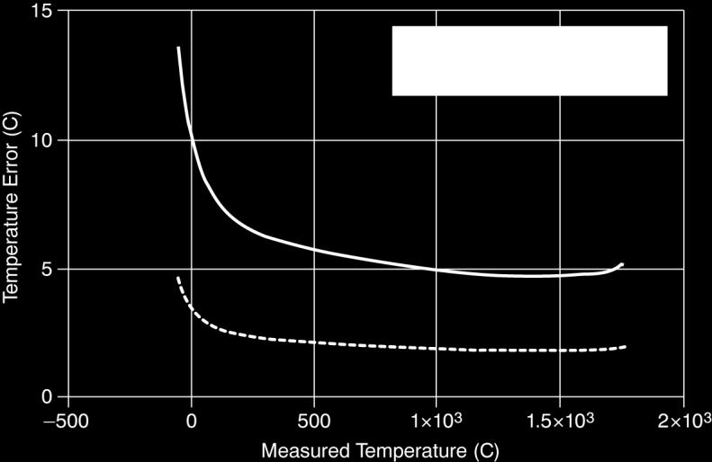
12 USB-2001-TC User's Guide Specifications Temperature error of J type thermocouple Temperature error of K type thermocouple Temperature error of R type thermocouple 12


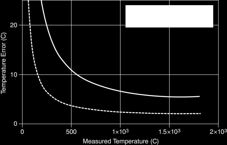
13 USB-2001-TC User's Guide Specifications Temperature error of S type thermocouple Temperature error of N type thermocouple Temperature error of B type thermocouple 13


14 USB-2001-TC User's Guide Specifications Temperature error of T type thermocouple Temperature error of E type thermocouple LED indicator Table 4. LED behavior Condition Steady green Blinking green Off Specification The device is powered and ready for operation. The device is powered, but not yet enumerated by the USB. The device is not powered or is in USB suspend. Power Table 5. Power specifications Parameter Current consumption from USB Suspend current Recommended warm-up time Specification 150 ma maximum, 100 ma typical 2.5 ma maximum 15 minutes 14
15 USB-2001-TC User's Guide Specifications Safety voltages Connect only voltages that are within these limits. Table 6. Safety voltage specifications Parameter Conditions Specification Isolation Channel-to-earth ground +30 V maximum (Note 3) Note 3: Measurement Category I is for measurements performed on circuits not directly connected to the electrical distribution system referred to as MAINS voltage. MAINS is a hazardous live electrical supply system that powers equipment. This category is for measurements of voltages from specially protected secondary circuits. Such voltage measurements include signal levels, special equipment, limited-energy parts of equipment, circuits powered by regulated low-voltage sources, and electronics. Bus interface Table 7. Bus specifications Parameter Specification USB specification USB 2.0 Full-Speed Device compatibility USB 1.1, USB 2.0 Mechanical Table 8. Mechanical specifications Parameter Dimensions Cable Length Weight Specification mm (L) x mm (W) x mm (H) 2.46 in. (L) x 1.50 in. (W) x 0.80 in. (H) 2 meters (6.5 feet) Approximately 116 g (4.1 oz) Environment Table 9. Environmental specifications Operating temperature range 0 to 55 C Storage temperature range 40 to 85 C Operating humidity 10 to 90% non-condensing Storage humidity 5 to 95% RH, noncondensing Maximum altitude 2,000 m (at 25 ºC ambient temperature) Pollution degree 2 Note 4: The USB-2001-TC is intended for indoor use only. 15
16 Declaration of Conformity Manufacturer: Address: Measurement Computing Corporation 10 Commerce Way Suite 1008 Norton, MA USA Category: Electrical equipment for measurement, control and laboratory use. Measurement Computing Corporation declares under sole responsibility that the product USB-2001-TC to which this declaration relates is in conformity with the relevant provisions of the following standards or other documents: EC EMC Directive 2004/108/EC: General Requirements, EN :2006 (IEC :2005). Emissions: EN (2007) / CISPR 11(2003): Radiated emissions: Group 1, Class A EN (2007) / CISPR 11(2003): Conducted emissions: Group 1, Class A Immunity: EN :2006, Particular requirements for sensitive test and measurement equipment for EMC unprotected applications. IEC (2001): Electrostatic Discharge immunity. IEC (2002): Radiated Electromagnetic Field immunity. IEC (2004): Electric Fast Transient Burst Immunity. IEC (2001): Surge Immunity. IEC (2003): Radio Frequency Common Mode Immunity. IEC (2004): Voltage Interrupts. To maintain compliance to the standards of this declaration, the following conditions must be met. The host computer, peripheral equipment, power sources, and expansion hardware must be CE compliant. All I/O cables must be shielded, with the shields connected to ground. I/O cables must be less than 3 meters (9.75 feet) in length. The host computer must be properly grounded. Declaration of Conformity based on tests conducted by National Instruments Corporation, Austin, TX, USA in November, We hereby declare that the equipment specified conforms to the above Directives and Standards. Carl Haapaoja, Director of Quality Assurance
17 Measurement Computing Corporation 10 Commerce Way Suite 1008 Norton, Massachusetts (508) Fax: (508)
USB-TC. Thermocouple Measurement. User's Guide. October Rev 10A Measurement Computing Corporation
 USB-TC Thermocouple Measurement User's Guide October 2016. Rev 10A Measurement Computing Corporation Trademark and Copyright Information Measurement Computing Corporation, InstaCal, Universal Library,
USB-1024LS. 24-bit Digital I/O Low-speed USB 2.0 device. User s Guide
 USB-1024LS 24-bit Digital I/O Low-speed USB 2.0 device User s Guide USB-1024LS USB-based Digital I/O Module User's Guide Document Revision 2A, May, 2006 Copyright 2006, Measurement Computing Corporation
PCI-PDISO8. Isolated Input and Relay Output. User's Guide
 PCI-PDISO8 Isolated Input and Relay Output User's Guide Document Revision 10A April 2012 Copyright 2012 Trademark and Copyright Information Measurement Computing Corporation, InstaCal, Universal Library,
WLS-IFC. USB-to-Wireless Interface. User's Guide
 WLS-IFC USB-to-Wireless Interface User's Guide Document Revision 5A April 2014 Copyright 2014 Trademark and Copyright Information Measurement Computing Corporation, InstaCal, Universal Library, and the
USB-201-OEM. Analog and Digital I/O. User's Guide
 USB-201-OEM Analog and Digital I/O User's Guide Document Revision 7A December 2014 Copyright 2014 Trademark and Copyright Information Measurement Computing Corporation, InstaCal, Universal Library, and
AI-EXP32. Analog Input Expansion Device for USB-2416 Series Devices. User's Guide
 AI-EXP32 Analog Input Expansion Device for USB-2416 Series Devices User's Guide Document Revision 4A September 2013 Copyright 2013 Trademark and Copyright Information Measurement Computing Corporation,
USB-201. Analog and Digital I/O. User's Guide. January Rev 7 Measurement Computing Corporation
 USB-201 Analog and Digital I/O User's Guide January 2019. Rev 7 Measurement Computing Corporation Trademark and Copyright Information Measurement Computing Corporation, InstaCal, Universal Library, and
USB-ERB24. USB-based 24-Channel Electromechanical Relay Interface Device. User's Guide. May Rev 8A Measurement Computing Corporation.
 USB-ERB24 USB-based 24-Channel Electromechanical Relay Interface Device User's Guide May 2016. Rev 8A Measurement Computing Corporation. Trademark and Copyright Information Measurement Computing Corporation,
USB-PDISO8/40. USB-based Isolated Input and Relay Output. User's Guide. September Rev 6 Measurement Computing Corporation
 USB-PDISO8/40 USB-based Isolated Input and Relay Output User's Guide September 2017. Rev 6 Measurement Computing Corporation Trademark and Copyright Information Measurement Computing Corporation, InstaCal,
PCI-DIO24H Digital I/O User's Guide
 PCI-DIO24H Digital I/O User's Guide Document Revision 3A, May, 2009 Copyright 2009, Measurement Computing Corporation Trademark and Copyright Information Measurement Computing Corporation, InstaCal, Universal
USB-SSR08. USB-based Solid-State 8 I/O Module Interface Device. User's Guide. January Rev 6A Measurement Computing Corporation
 USB-SSR08 USB-based Solid-State 8 I/O Module Interface Device User's Guide January 2017. Rev 6A Measurement Computing Corporation Trademark and Copyright Information Measurement Computing Corporation,
E-DIO24. Ethernet-based Digital I/O. User's Guide. Preliminar y
 E-DIO24 Ethernet-based Digital I/O User's Guide Preliminar y Document Revision 2A April 2016 Trademark and Copyright Information Measurement Computing Corporation, InstaCal, Universal Library, and the
PCI-DAS08 Analog input and Digital I/O User's Guide
 PCI-DAS08 Analog input and Digital I/O User's Guide Document Revision 5A, June, 2006 Copyright 2006, Measurement Computing Corporation Trademark and Copyright Information Measurement Computing Corporation,
PCIe-DIO24. Digital Input/Output. User's Guide. September Rev 3 Measurement Computing Corporation
 PCIe-DIO24 Digital Input/Output User's Guide September 2018. Rev 3 Measurement Computing Corporation Trademark and Copyright Information Measurement Computing Corporation, InstaCal, Universal Library,
USB-231. Analog and Digital I/O. User's Guide
 USB-231 Analog and Digital I/O User's Guide Document Revision 3 October 2017 Copyright 2017 Trademark and Copyright Information Measurement Computing Corporation, InstaCal, Universal Library, and the Measurement
PCI-DDA08/16. Analog Output and Digital I/O. User's Guide
 PCI-DDA08/16 Analog Output and Digital I/O User's Guide Document Revision 3A March 2012 Copyright 2012 Trademark and Copyright Information Measurement Computing Corporation, InstaCal, Universal Library,
USB Multi-sensor Measurement and Data Logger. User's Guide
 USB-5203 Multi-sensor Measurement and Data Logger User's Guide Document Revision 14A January 2015 Copyright 2015 Trademark and Copyright Information Measurement Computing Corporation, InstaCal, Universal
CIO-DAS08/JR Analog and Digital I/O User s Guide
 CIO-DAS08/JR Analog and Digital I/O User s Guide Document Revision 5A, January, 2011 Copyright 2011, Measurement Computing Corporation Trademark and Copyright Information Measurement Computing Corporation,
USB-234. Analog and Digital I/O. User's Guide. January Rev 4 Measurement Computing Corporation
 USB-234 Analog and Digital I/O User's Guide January 2019. Rev 4 Measurement Computing Corporation Trademark and Copyright Information Measurement Computing Corporation, InstaCal, Universal Library, and
USB-DIO96H/50. High-drive Digital I/O. User's Guide. Hardware Revision 2
 USB-DIO96H/50 High-drive Digital I/O User's Guide Hardware Revision 2 Document Revision 8A September 2013 Copyright 2013 Trademark and Copyright Information Measurement Computing Corporation, InstaCal,
USB-231-OEM. Analog and Digital I/O. User's Guide. January Rev 4 Measurement Computing Corporation
 USB-231-OEM Analog and Digital I/O User's Guide January 2019. Rev 4 Measurement Computing Corporation Trademark and Copyright Information Measurement Computing Corporation, InstaCal, Universal Library,
E-TC. Ethernet-based 8-Channel Thermocouple Input Device. User's Guide. July Rev 3A Measurement Computing Corporation
 E-TC Ethernet-based 8-Channel Thermocouple Input Device User's Guide July 2016. Rev 3A Measurement Computing Corporation Trademark and Copyright Information Measurement Computing Corporation, InstaCal,
Chapter 1 Introducing the OM-USB Functional block diagram... 5
 Table of Contents Preface About this User's Guide... 4 What you will learn from this user's guide... 4 Conventions in this user's guide... 4 Where to find more information... 4 Safety guidelines... 4 Chapter
CIO-DO48H, CIO-DO96H and CIO-DO192H. User s Guide
 CIO-DO48H, CIO-DO96H and CIO-DO192H User s Guide Revision 4A April, 2001 Trademark and Copyright Information Measurement Computing Corporation, InstaCal, Universal Library, and the Measurement Computing
USB-TEMP-AI. Temperature and Voltage Measurement. User's Guide
 USB-TEMP-AI Temperature and Voltage Measurement User's Guide Document Revision 6A March 2013 Copyright 2013 Trademark and Copyright Information Measurement Computing Corporation, InstaCal, Universal Library,
PC-CARD-D24/CTR3 Digital I/O and Counter Board User s Guide
 PC-CARD-D24/CTR3 Digital I/O and Counter Board User s Guide Document Revision 6, April, 2007 Copyright 2007, Measurement Computing Corporation Your new Measurement Computing product comes with a fantastic
WLS-TC Specifications
 Specifications Document Revision 1.0, February, 2010 Copyright 2010, Measurement Computing Corporation Typical for 25 C unless otherwise specified. Specifications in italic text are guaranteed by design.
Operating Manual. USB-based High-Precision 8-channel Temperature Measurement device and Data Logger MODEL NO
 Operating Manual USB-based High-Precision 8-channel Temperature Measurement device and Data Logger MODEL NO. 18200-75 The 18200-75 is a USB 2.0 full-speed, thermocouple input device that is fully compatible
USB-1208HS-4AO. High-Speed Analog Input and Digital I/O. User's Guide
 USB-1208HS-4AO High-Speed Analog Input and Digital I/O User's Guide Document Revision 3A March 2013 Copyright 2013 Trademark and Copyright Information Measurement Computing Corporation, InstaCal, Universal
SCC-AO10 Isolated Analog Output Module
 USER GUIDE SCC-AO10 Isolated Analog Output Module Conventions The SCC-AO10 is an isolated voltage output module with an output range of ±10 V. The output voltage level is controlled by the DAC output of
SCXI -1313A Terminal Block
 INSTALLATION GUIDE SCXI -1313A Terminal Block Conventions This guide describes how to install and use the SCXI-1313A terminal block with an SCXI-1125 module. The SCXI-1313A terminal block is shielded and
Specifications
 Specifications 18200-40 Cole-Parmer Instrument Company 625 East Bunker Court Vernon Hills, Illinois 60061-1844 (847) 549-7600 (847) 247-2929 (Fax) 800-323-4340 www.coleparmer.com e-mail: techinfo@coleparmer.com
PCI-DAS1000 Multifunction Analog & Digital I/O User's Guide
 PCI-DAS1000 Multifunction Analog & Digital I/O User's Guide Document Revision 3A, March, 2009 Copyright 2009, Measurement Computing Corporation Trademark and Copyright Information Measurement Computing
USB-3110 USB-based Analog Output User Guide
 USB-3110 USB-based Analog Output User Guide Document Revision 4A, January, 2011 Copyright 2011, Measurement Computing Corporation Trademark and Copyright Information Measurement Computing Corporation,
AI-EXP32. Analog Input Expansion Module for USB-2416 Modules. User's Guide
 AI-EXP32 Analog Input Expansion Module for USB-2416 Modules User's Guide Document Revision 3, January, 2011 Copyright 2011, Measurement Computing Corporation Your new Measurement Computing product comes
TC Channel Thermocouple Input USB/Ethernet DAQ Device. User's Guide
 TC-32 32-Channel Thermocouple Input USB/Ethernet DAQ Device User's Guide Document Revision 3A March 2016 Copyright 2016 Trademark and Copyright Information Measurement Computing Corporation, InstaCal,
PCI-DIO24 24-bit, Logic-level Digital I/O User's Guide
 PCI-DIO24 24-bit, Logic-level Digital I/O User's Guide Document Revision 3, May, 2009 Copyright 2009, Measurement Computing Corporation Your new Measurement Computing product comes with a fantastic extra
CIO-DIO48 Digital Input/Output Board User s Guide
 CIO-DIO48 Digital Input/Output Board User s Guide Document Revision 1A, December, 2006 Copyright 2006, Measurement Computing Corporation Trademark and Copyright Information Measurement Computing Corporation,
Chapter 1 Introducing the OM-USB Functional block diagram... 5
 Table of Contents Preface About this User's Guide... 4 What you will learn from this user's guide... 4 Conventions in this user's guide... 4 Where to find more information... 4 Chapter 1 Introducing the
Operating Manual. USB-based High-Precision 8-channel Temperature Measurement Module MODEL NO
 Operating Manual USB-based High-Precision 8-channel Temperature Measurement Module MODEL NO. 18200-30 The 18200-30 is a USB 2.0 full-speed, temperature measurement module that is fully compatible with
Chapter 1 Introducing the OM-NET-TC... 6 Ethernet interface... 6 Functional block diagram... 6
 Table of Contents Preface About this User's Guide... 5 What you will learn from this user's guide... 5 Conventions in this user's guide... 5 Where to find more information... 5 Chapter 1 Introducing the
SCXI OFFSET-NULL AND SHUNT-CALIBRATION HIGH-VOLTAGE TERMINAL BLOCK INSTALLATION GUIDE
 SCXI -1321 OFFSET-NULL AND SHUNT-CALIBRATION HIGH-VOLTAGE TERMINAL BLOCK INSTALLATION GUIDE Conventions This guide describes how to install and use the SCXI-1321 offset-null and shunt-calibration terminal
WLS-IFC USB-to-Wireless Interface Module User's Guide
 WLS-IFC USB-to-Wireless Interface Module User's Guide Document Revision 3, January, 2007 Copyright 2007, Measurement Computing Corporation Your new Measurement Computing product comes with a fantastic
PCM-DAC02. PCMCIA Dual Analog Outputs. User s Manual
 PCM-DAC02 PCMCIA Dual Analog Outputs User s Manual Revision 3 August, 2001 MEGA-FIFO, the CIO prefix to data acquisition board model numbers, the PCM prefix to data acquisition board model numbers, PCM-DAS08,
PCI-DIO24/LP Digital Input/Output User's Guide
 PCI-DIO24/LP Digital Input/Output User's Guide Document Revision 7, May, 2009 Copyright 2009, Measurement Computing Corporation Your new Measurement Computing product comes with a fantastic extra Management
USB-TC-AI. 8-Channel Thermocouple Input and Voltage Input Module. User's Guide
 USB-TC-AI 8-Channel Thermocouple Input and Voltage Input Module User's Guide Document Revision 2, July, 2007 Copyright 2007, Measurement Computing Corporation Your new Measurement Computing product comes
Chapter 1 Introducing the OM-USB-1608FS-Plus... 6 Functional block diagram... 6
 Table of Contents Preface About this User's Guide... 5 What you will learn from this user's guide... 5 Conventions in this user's guide... 5 Where to find more information... 5 Chapter 1 Introducing the
PCIM-DAS1602/16. Analog & Digital I/O. User's Guide
 PCIM-DAS1602/16 Analog & Digital I/O User's Guide Document Revision 6A January 2014 Copyright 2014 Trademark and Copyright Information Measurement Computing Corporation, InstaCal, Universal Library, and
Distributed by MicroDAQ.com, Ltd. (603) WEB-TEMP. Web-Enabled Sensor Measurement. User's Guide
 WEB-TEMP. Web-Enabled Sensor Measurement. User's Guide") WEB-TEMP Web-Enabled Sensor Measurement User's Guide Document Revision 5 March 2013 Copyright 2013 Your new Measurement Computing product comes with a fantastic extra Management committed to your satisfaction!
WEB-TEMP Web-Enabled Sensor Measurement User's Guide Document Revision 5 March 2013 Copyright 2013 Your new Measurement Computing product comes with a fantastic extra Management committed to your satisfaction!
OPERATING INSTRUCTIONS AND SPECIFICATIONS NI 9476E. 32-Channel, 24 V Sourcing Digital Output Module
 OPERATING INSTRUCTIONS AND SPECIFICATIONS NI 9476E 32-Channel, 24 V Sourcing Digital Output Module This document describes how to use the National Instruments 9476E and includes dimensions, connector assignments,
CIO-DIO24 Digital Input/Output Board User s Guide
 CIO-DIO24 Digital Input/Output Board User s Guide Document Revision 1A, January, 2007 Copyright 2007, Measurement Computing Corporation Trademark and Copyright Information Measurement Computing Corporation,
CIO-DIO96 Digital Input/Output Board User s Guide
 CIO-DIO96 Digital Input/Output Board User s Guide Document Revision 1A, December, 2006 Copyright 2006, Measurement Computing Corporation Trademark and Copyright Information Measurement Computing Corporation,
CIO-DIO192 Digital Input/Output Board User s Guide
 CIO-DIO192 Digital Input/Output Board User s Guide Document Revision 1A, December, 2006 Copyright 2006, Measurement Computing Corporation Trademark and Copyright Information Measurement Computing Corporation,
TM3TI4 module TM3-4 inputs temperature
 Characteristics module TM3-4 inputs temperature Main Range of product Product or component type Range compatibility Analogue input number 4 Analogue input type Complementary Analogue input resolution Permissible
USB-500 Series Getting Started Contents
 USB-500 Series Getting Started Contents System requirements and recommendations... 2 USB-501-PRO Safety Agreement... 2 Installing the software... 3 Installing USB-500 Series Data Loggers... 4 Running the
USB Analog Input and Digital I/O Measurement and Control. User's Guide
 USB-2633 Analog Input and Digital I/O Measurement and Control User's Guide Document Revision 3A July 2014 Copyright 2014 Trademark and Copyright Information Measurement Computing Corporation, InstaCal,
NI REM Remote I/O Overview DATASHEET. Analog Output Module for Remote I/O
 DATASHEET NI REM-11115 Analog Output Module for Remote I/O Four voltage output ranges to choose from (0 V to 10V, ±10V, 0 V to 5 V, and ±5V) Two current output ranges to choose from (0 ma to 20mA, 4 ma
TM3TM3 module TM3-2 temperature inputs and 1 analog output
 Characteristics module TM3-2 temperature inputs and 1 analog output Main Range of product Product or component type Range compatibility Analogue input number 2 Analogue input type Analogue output number
PCI-DAS1001 Multifunction Analog & Digital I/O User's Guide
 PCI-DAS1001 Multifunction Analog & Digital I/O User's Guide Document Revision 3A, March, 2009 Copyright 2009, Measurement Computing Corporation Trademark and Copyright Information Measurement Computing
TBX-1316 High-Voltage Attenuator Terminal Block
 INSTALLATION GUIDE TBX-1316 High-Voltage Attenuator Terminal Block This guide describes how to install and use the TBX-1316 high-voltage attenuator terminal block with the following modules: SCXI-1125
OPERATING INSTRUCTIONS AND SPECIFICATIONS. NI 9208E 16-Channel, ±20 ma, 24-Bit Analog Input Module
 OPERATING INSTRUCTIONS AND SPECIFICATIONS NI 9208E 16-Channel, ±20 ma, 24-Bit Analog Input Module This document describes how to use the National Instruments 9208E and includes dimensions, pin assignments,
SCC-RLY01 Relay Module
 USER GUIDE SCC-RLY01 Relay Module Conventions The SCC-RLY01 contains one single-pole double-throw (SPDT) nonlatching relay capable of switching 5 A at 30 VDC when using an SC-2345 or SC-2350, or 250 VAC
IVN Safety Guidelines GETTING STARTED GUIDE. 100BASE-T1 Media Converter
 #6-32 GETTING STARTED GUIDE IVN-8561 100BASE-T1 Media Converter IVN-8561 100BASE-T1 Media Converter POWER P1 P3 MASTER LINK/ACT POWER PORT 4 5V 2.8W MAX This document describes how to begin using the IVN-8561
TM3TI8T module TM3-8 inputs temperature
 Characteristics module TM3-8 inputs temperature Main Range of product Product or component type Range compatibility Analogue input number 8 Analogue input type Complementary Analogue input resolution Input
TM3AI4 module TM3-4 analog inputs
 Characteristics module TM3-4 analog inputs Main Range of product Product or component type Range compatibility Analogue input number 4 Analogue input type Complementary Analogue input resolution Permissible
USB-1024HLS USB-based Digital I/O Module User's Guide
 USB-1024HLS USB-based Digital I/O Module User's Guide Document Revision 2, May, 2006 Copyright 2006, Measurement Computing Corporation Your new Measurement Computing product comes with a fantastic extra
Electrical. SPECIFICATIONS SH Cable
 SPECIFICATIONS SH96-96-1 Cable When this symbol is marked on a product, it denotes a warning advising you to take precautions to avoid electrical shock. This icon denotes a caution, which advises you of
PCI-DAS1002 Multifunction Analog & Digital I/O User's Guide
 PCI-DAS1002 Multifunction Analog & Digital I/O User's Guide Document Revision 5A, March, 2009 Copyright 2009, Measurement Computing Corporation Trademark and Copyright Information Measurement Computing
NI REM Remote I/O Overview DATASHEET. Bus Coupler for Remote I/O
 DATASHEET NI REM-11180 Bus Coupler for Remote I/O Deterministic communication and data transfer to host system EtherCAT cycle time of
OBSOLETE. Isolated, Linearized, Thermocouple Input 3B47 FEATURES APPLICATIONS PRODUCT OVERVIEW FUNCTIONAL BLOCK DIAGRAM
 FEATURES Interfaces, amplifies, filters, isolates, & linearizes analog input voltages from a J, K, T, E, R, S or B-type thermocouple Thermocouple input signal is internally linearized High accuracy internal
USB AO USB-based Multi-function I/O module User's Guide
 USB-2416-4AO USB-based Multi-function I/O module User's Guide Document Revision 1, January, 2009 Copyright 2009, Measurement Computing Corporation Your new Measurement Computing product comes with a fantastic
NI REM Remote I/O Overview DATASHEET. Digital Input Module for Remote I/O
 DATASHEET NI REM-11154 Digital Input Module for Remote I/O Read digital input frequencies up to 5 khz Adjustable filter time to improve measurement quality Spring-terminal connectors allow fast wiring
NI What You Need to Get Started. Unpacking INSTALLATION GUIDE. This document explains how to set up your NI 8262 expansion module.
 INSTALLATION GUIDE NI 8262 This document explains how to set up your NI 8262 expansion module. What You Need to Get Started Unpacking To set up and use your NI 8262 module, you need the following: A PXI
Installation Instructions
 Installation Instructions Cat. No. 1771-IQ16 Series C This document provides information on: The dc isolated input module is shipped in static-shielded packaging to guard against electrostatic discharge
NI REM Remote I/O Overview DATASHEET. Digital Output Module for Remote I/O
 DATASHEET NI REM-11178 Digital Output Module for Remote I/O Short circuit and overload protection Drives up to 500 ma per channel (up to 8A per module) Spring-terminal connectors allow fast wiring without
PC-CARD-DAC08 Analog Output Board User s Guide
 PC-CARD-DAC08 Analog Output Board User s Guide Document Revision 2, December, 2006 Copyright 2006, Measurement Computing Corporation Your new Measurement Computing product comes with a fantastic extra
CIO-DAS802/16 Analog Input and Digital I/O User's Guide
 CIO-DAS802/16 Analog Input and Digital I/O User's Guide Document Revision 5A, March, 2010 Copyright 2010, Measurement Computing Corporation Trademark and Copyright Information Measurement Computing Corporation,
TM3TI4 module TM3-4 inputs temperature
 Characteristics module TM3-4 inputs temperature Complementary Analogue input resolution Permissible continuous overload Input impedance LSB value Conversion time Sampling duration Main Range of product
PCI-DAS1200/JR Multifunction Analog Input and Digital I/O User's Guide
 PCI-DAS1200/JR Multifunction Analog Input and Digital I/O User's Guide Document Revision 6, March, 2009 Copyright 2009, Measurement Computing Corp. Trademark and Copyright Information Measurement Computing
NI Serial Hardware Specifications Guide
 NI Serial Hardware Specifications Guide Contents This document lists safety and compliance information for NI Serial hardware, as well as physical specifications, software characteristics, and recommended
PC-CARD-DAC08. User s Manual
 PC-CARD-DAC8 Analog Outputs & Digital I/O User s Manual Revision March, 2 (C) Copyright 2, Measurement Computing Corporation MEGA-FIFO, the CIO prefix to data acquisition board model numbers, the PCM prefix
ATS22C11S6U soft starter-ats22-control110vpower208v(30hp)/230v(40hp)/460v(75hp)/575v(100h
/230v(40hp)/460v(75hp)/575v(100h") Characteristics soft starter-ats22-control110vpower208v(30hp)/230v(40hp)/460v(75hp)/575v(100h Complementary Assembly style Function available Power supply voltage limits Main Range of product Altistart
Characteristics soft starter-ats22-control110vpower208v(30hp)/230v(40hp)/460v(75hp)/575v(100h Complementary Assembly style Function available Power supply voltage limits Main Range of product Altistart
Chapter 2 Installing the OM-USB-1608FS... 9 What comes with your OM-USB-1608FS shipment?... 9 Hardware... 9 Additional documentation...
 Table of Contents Preface About this User's Guide... 5 What you will learn from this user's guide... 5 Conventions in this user s guide... 5 Where to find more information... 5 Chapter 1 Introducing the
USB based Counter/Timer User's Guide
 USB-4301 9513-based Counter/Timer User's Guide Document Revision 5, March, 2009 Copyright 2009, Measurement Computing Corporation Your new Measurement Computing product comes with a fantastic extra Management
PC104-CTR10HD. User s Manual
 PC104-CTR10HD User s Manual Revision 2 October, 2000 MEGA-FIFO, the CIO prefix to data acquisition board model numbers, the PCM prefix to data acquisition board model numbers, PCM-DAS08, PCM-D24C3, PCM-DAC02,
USB to RS232 Converter USB-013 (Rev3) User s Manual Ver. 1.2 HuMANDATA LTD.
 User s Manual Ver. 1.2 HuMANDATA LTD.") USB to RS232 Converter USB-013 (Rev3) User s Manual Ver. 1.2 HuMANDATA LTD. Table of Contents Precautions... 1 Revision History... 2 Introduction... 2 1. Overview... 3 2. Power Supply... 3 3. Specifications...
USB to RS232 Converter USB-013 (Rev3) User s Manual Ver. 1.2 HuMANDATA LTD. Table of Contents Precautions... 1 Revision History... 2 Introduction... 2 1. Overview... 3 2. Power Supply... 3 3. Specifications...
NI PXI-2567 Specifications
 NI PXI-2567 Specifications 64-Channel Relay Driver Module This document lists specifications for the NI PXI-2567 relay driver module. All specifications are subject to change without notice. Visit ni.com/manuals
Preface About this User's Guide... iv What you will learn from this user's guide... iv Conventions in this user's guide... iv
 Table of Contents Preface About this User's Guide... iv What you will learn from this user's guide... iv Conventions in this user's guide... iv Chapter 1 Introducing the PCI-PDISO8... 1-1 Overview: PCI-PDISO8
E Ethernet-based High-speed Multifunction DAQ. User's Guide
 E-1608 Ethernet-based High-speed Multifunction DAQ User's Guide Document Revision 2A April 2016 Trademark and Copyright Information Measurement Computing Corporation, InstaCal, Universal Library, and the
NI PXI-1042 Series Power Supply Shuttle
 USER GUIDE NI PXI-1042 Series Power Supply Shuttle Introduction Unpacking The NI PXI-1042 Series power supply shuttle is a replacement part for the NI PXI-1042 Series chassis. To minimize downtime caused
USB-PDISO8. USB-based Isolated Input and Relay Output. User's Guide
 USB-PDISO8 USB-based Isolated Input and Relay Output User's Guide Document Revision 4, August, 2006 Copyright 2006, Measurement Computing Corporation Your new Measurement Computing product comes with a
ATS22C21S6U softstarter-ats22-control110vpower208v(60hp)/230v(75hp)/460v(150hp)/575v(200hp)
/230v(75hp)/460v(150hp)/575v(200hp)") Characteristics softstarter-ats22-control110vpower208v(60hp)/230v(75hp)/460v(150hp)/575v(200hp) Main Range of product Altistart 22 Product or component type Product destination Product specific application
Characteristics softstarter-ats22-control110vpower208v(60hp)/230v(75hp)/460v(150hp)/575v(200hp) Main Range of product Altistart 22 Product or component type Product destination Product specific application
MINI-PS AC/10-15DC/8
 Primary-Switched Power Supply, Narrow Design Data Sheet 08/2004 MINI POWER provides: An extra narrow design, with widths of 22.5 mm, 45 mm, and 67.5 mm (0.886, 1.772, and 2.657 in.) Global use due to a
USB Multifunction Measurement and Control. User's Guide
 USB-2627 Multifunction Measurement and Control User's Guide Document Revision 3A July 2014 Copyright 2014 Trademark and Copyright Information Measurement Computing Corporation, InstaCal, Universal Library,
LGR-5325 Specifications
 s Revision 1.0, April, 2010 Copyright 2010, Measurement Computing Corporation s All specifications are subject to change without notice. Typical for 25 C unless otherwise specified. s in italic text are
General Specifications. P2-08THM Analog Input
 General Specifications Operating Temperature Storage Temperature Humidity Environmental Air Vibration Shock Field to Logic Side Isolation Heat Dissipation Enclosure Type Agency Approvals Module Keying
USB-2408 Series. 24-Bit Multifunction Temperature and Voltage Devices USB-2408 USB AO. User's Guide
 USB-2408 Series 24-Bit Multifunction Temperature and Voltage Devices USB-2408 USB-2408-2AO User's Guide Document Revision 3 June 2014 Copyright 2014 Your new Measurement Computing product comes with a
PLQL/$% (LJKW $QDORJ,QSXW 7ZR
 nalog and Digital I/O User's Guide minilab 1008 USB-based Analog and Digital I/O Module User's Guide Document Revision 8, May, 2006 Copyright 2006, Measurement Computing Corporation Trademark and Copyright
USB Definitions. Conditions. Analog Input SPECIFICATIONS. 8 AI (10 ks/s), 4 DIO USB Multifunction I/O Device
, 4 DIO USB Multifunction I/O Device") SPECIFICATIONS USB-6000 8 AI (10 ks/s), 4 DIO USB Multifunction I/O Device Definitions Warranted specifications describe the performance of a model under stated operating conditions and are covered by
SPECIFICATIONS USB-6000 8 AI (10 ks/s), 4 DIO USB Multifunction I/O Device Definitions Warranted specifications describe the performance of a model under stated operating conditions and are covered by
PCI-QUAD04. Four-Channel Quadrature Encoder Input Board. User's Guide
 HM PCI-QUAD04.doc i PCI-QUAD04 Four-Channel Quadrature Encoder Input Board User's Guide Document Revision 5, June, 2006 Copyright 2006, Measurement Computing Corporation Your new Measurement Computing