Copyright Information: Firmware (Software) Agreement:
|
|
|
- Michael Dickerson
- 5 years ago
- Views:
Transcription
1 Maintenance Manual
2 Copyright Information: CG Triumvirate is a trademark of Agfa Corporation. CG Times based upon Times New Roman under license from the Monotype Corporation. Windows is a registered trademark of the Microsoft Corporation. All other brand and product names are trademarks, service marks, registered trademarks, or registered service marks of their respective companies. Firmware (Software) Agreement: The enclosed Firmware (Software) resident in the Printer is owned by Licensor or its suppliers and is licensed for used only on a single printer in the user s Trade or Business. The User agrees not to, and not to authorize or permit any other person or party to, duplicate or copy the Firmware or the information contained in the non-volatile or programmable memory. The firmware (Software) is protected by applicable copyright laws and Licensor retains all rights not expressly granted. In no event will Licensor or its suppliers be liable for any damages or loss, including direct, incidental, economic, special, or consequential damages, arising out of the use or inability to use the Firmware (Software). Information in this document is subject to change without notice and does not represent a commitment on the part of Datamax-O Neil Corporation. No part of this manual may be reproduced or transmitted in any form or by any means, for any purpose other than the purchaser's personal use, without the expressed written permission of Datamax-O Neil Corporation. All rights reserved. Part Number , Rev. A Copyright 2009 by Datamax-O Neil Corporation
3 Contents 1 Overview 2 3 Troubleshooting 4 Removal and Replacement Maintenance and Adjustments i
4 ii
5 1 Overview 1.0 Introduction About this Printer... 2 i
6 ii
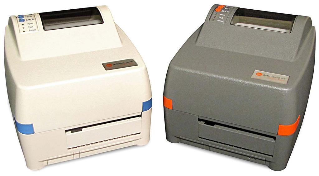
7 1.0 Introduction This manual is intended for use by qualified service personnel in the maintenance and repair of Datamax E-Class model printers. It primarily includes technical information relating to the printer s electrical and mechanical components. For related information, refer to the following documents, available at For general user information, reference the Operator s Manual (part number ). For software documentation, reference the Class Series 2 Programmer s Manual (part number ). Important Information: The exclamation point inside an equilateral triangle is intended to alert the technician to the presence of important operating, servicing, or maintenance information. Always, as with all electrical equipment, follow basic safety precautions to avoid personal injury and/or printer damage. Overview 1-1
8 1.1 About this Printer The user-assessable components of the printer are shown below. Note that some items are optional equipment. Front Panel Thumbwheel Printhead Assembly Media Hub Media Flange Printhead Media Sensor (optional AMS shown) Printhead Latch Platen 1-2 Overview
9 2 Maintenance and Adjustments 2.0 Introduction Maintenance Cleaning the Printhead Cotton Swab Procedure Cleaning Card Procedure Cleaning Film Procedure Cleaning the Platen Cleaning the Media Sensor Media Width Adjustment Ribbon Width Adjustment Printhead Adjustment Resetting the Printer Downloading Firmware and Fonts Media Sensor Calibration Auto Calibration Manual Calibration i
10 ii
11 2.0 Introduction This section covers maintenance and alignment procedures. 2.1 Maintenance Recommended items, techniques, and schedules to keep the printer in top working order are detailed below. The following items will help you safely and effectively maintain the printer: Isopropyl alcohol Cotton swabs Clean, lint-free cloth Soft-bristle brush Soapy water/mild detergent Compressed air Printhead Cleaning Cards or Printhead Cleaning Film For your safety and to avoid damaging the unit, always turn OFF the power switch and unplug the AC power cord before servicing the printer. CAUTION Isopropyl alcohol is a flammable liquid -- take proper precautions when using this solvent. Recommended Maintenance Schedule Component / Area Cleaning Interval Method / Supplies Printhead After every roll of media. A cotton swab dampened with isopropyl alcohol then wiped across the surface and, if necessary, Printhead Cleaning Cards or Cleaning Film when needed; see Section Platen After every roll of media. A cotton swab or cloth dampened with isopropyl alcohol wiped across the roller, rotating as needed to clean the entire surface; see Section Peel-Off Roller After every roll of media. Rotate the peel-off roller and clean it thoroughly using isopropyl alcohol and a cotton swab. Media Path / Media Sensor / Peel Bar As needed. Compressed air or a soft brush to remove all debris, and isopropyl alcohol to remove adhesive buildup; see Section Interior As needed. Compressed air or a soft brush to remove all debris. Exterior Surfaces As needed. A cloth dampened with mild detergent wiped across the surface until clean. Maintenance and Adjustments 2-1

 in the direction of print can indicate a dirty or faulty Printhead. 2.1.")
12 2.1.1 Cleaning the Printhead If print quality declines (symptoms can include non-compliant bar codes, print dropouts, streaks, etc.), the typical cause is debris buildup on the Printhead. If not removed, this buildup can lead to element failure, reducing the service life of the Printhead. Depending upon the media, ribbon, and printing parameters used, different methods and supplies are recommended to clean the Printhead. CAUTION NEVER use a sharp object on the Printhead; damage can result. Faulty Label: Streaks (e.g., white lines) in the direction of print can indicate a dirty or faulty Printhead Cotton Swab Procedure This procedure is recommended when using direct thermal media, or thermal transfer media with wax ribbon. 1. Stop printing. Allow the Printhead to cool. 2. Raise the Printhead Assembly then remove media and ribbon from the printer. 3. Turn OFF and unplug the printer. Using a Cotton Swab moistened (not soaked) with isopropyl alcohol, gently wipe the entire Printhead surface clean, while paying special attention to the Burn Line to ensure all buildup is removed. Allow the Printhead to dry. Burn Line Printhead buildup Printhead Latch Cotton Swab 2-2 Maintenance and Adjustments
13 4. Reinstall media (and ribbon, if needed). Lower and latch the Printhead Assembly. Adjust the Media Width Setting. Close the cover then plug in and turn ON the printer. Print then examine several sample labels. If symptoms persist, see Section ; otherwise, this completes the procedure Cleaning Card Procedure This procedure is recommended when using direct thermal media, thermal transfer media with wax ribbon, or if symptoms persist after performing the Cotton Swab Procedure (Section ). 1. Stop printing. Allow the Printhead to cool. 2. Raise the Printhead Assembly then remove media and ribbon from the printer. 3. Place a Cleaning Card under the Printhead. 4. Lower and latch the Printhead Assembly then zero the Media Width Setting; see Section Repeatedly press the FEED Key until the Cleaning Card exits the printer. 6. Reinstall media (and ribbon, if needed). Lower and latch the Printhead Assembly then adjust the Media Width Setting. Close the cover. Print then examine several sample labels. If symptoms persist, see Section ; otherwise, this completes the procedure Cleaning Film Procedure This procedure is recommended when using thermal transfer media with resin ribbon, a Heat setting above 21, or if symptoms persist after the other cleaning methods have been tried. 1. Stop printing. Allow the Printhead to cool. 2. Raise the Printhead Assembly then remove media and ribbon from the printer. 3. Place a sheet of Cleaning Film under the Printhead. 4. Lower and latch the Printhead Assembly then zero the Media Width Setting; see Section Repeatedly press the FEED Key until the Cleaning Film exits the printer. 6. Turn OFF and unplug the printer. Clean the Printhead using a Cotton Swab; see Section Allow the Printhead to dry. 7. Reinstall media and ribbon. Lower and latch the Printhead Assembly then adjust the Media Width Setting. Close the cover. Print then examine several sample labels. If symptoms persist, see Section 3.2. Maintenance and Adjustments 2-3
14 2.1.2 Cleaning the Platen The Platen, if contaminated with grit, label adhesive, or ink can cause a decline in print quality and, in extreme cases, cause labels to adhere to the roller. Clean the Platen as follows: CAUTION NEVER use a sharp object on the Platen. 1. Turn OFF and unplug the printer. Move media away from the Platen. 2. Using a Cotton Swab (or lint-free cloth) dampened with isopropyl alcohol, gently wipe the Platen clean, rotating it as needed to clean the entire surface. Allow the Platen to dry. 3. Reinstall media. Latch the Printhead Assembly and close the cover. Platen Cotton Swab Cleaning the Media Sensor The Media Sensor, if covered with paper dust or adhesive, can cause media sensing and positioning problems. Clean the Media Sensor as follows: 1. Turn OFF and unplug the printer. Remove media. 2. Using a brush or compressed air, remove all debris from the Media Sensor. Note: To remove adhesive buildup, wipe the Media Sensor clean using a Cotton Swab dampened with isopropyl alcohol; allow the sensor to dry before resuming operation. 2-4 Maintenance and Adjustments
15 Stationary Media Sensor Location: Printhead Assembly Stationary Media Sensor Cotton Swab Adjustable Media Sensor Location: Printhead Assembly Adjustable Media Sensor Cotton Swab Maintenance and Adjustments 2-5
 While facing the front of the printer Turning the Thumbwheel clockwise increases the effect.")

16 2.2 Media Width Adjustment To prevent wear on the Printhead and Platen, adjust the printer when using media that is less than four inches (102 mm) wide, as follows: 1. Load media. Print a batch of labels. (Simultaneously press F2 and F3, or send a format from the host.) While facing the front of the printer Turning the Thumbwheel clockwise increases the effect. Turning the Thumbwheel counterclockwise decreases the effect. Note: The Thumbwheel is numbered for reference, where zero is the lowest setting and nine is the highest. 2. While the labels print, adjust the Thumbwheel until the image begins to fade. Over-adjustment produces an image that fades across the label. 3. Then turn the Thumbwheel in the opposite direction until the full image is produced. Correct adjustment produces a complete image, with even print contrast across the label. Note: Under-adjustment can cause ribbon wrinkling and excessive wear on the Printhead and Platen. If the media moves excessively rightward while printing, the Thumbwheel should be adjusted clockwise. 2-6 Maintenance and Adjustments
17 2.3 Ribbon Width Adjustment If equipped with the thermal transfer option, the Ribbon Tension Adjustment Knob allows the optimum amount tension to be applied to the ribbon, as follows: 1. Turn OFF the printer. Remove ribbon, if installed. 2. While holding the Hub, rotate the Ribbon Tension Adjustment Knob to match the ribbon width, according on the table below. Ribbon Width Direction of Rotation 1-2 inches (25 51 mm) Clockwise 2-4 inches ( mm) Counterclockwise 3. Ensure that the Ribbon Tension Adjustment Knob is turned fully into position and will no longer rotate. Note: Never force or over-tighten the Ribbon Tension Adjustment Knob. 2.4 Printhead Adjustment If necessary, print quality can be mechanically adjusted. Although factory set for optimum print quality, some media types (for example, heavy card stock) may require a slight readjustment if quality changes. 1. Load media. Print a batch of labels. (Simultaneously press F2 and F3, or send a format from the host.) Maintenance and Adjustments 2-7
18 2. While the labels print, turn the Printhead Adjustment Screw until optimum print quality is obtained. Printhead Adjustment Screw Printhead Assembly Note: Never over-tighten the Printhead Adjustment Screw; damage can result. Also, if thermal transfer equipped, use the opening in the Ribbon Handler Assembly to access the screw. 2.5 Resetting the Printer To return the printer to factory default settings proceed as follows: Turn ON the printer, and then while all 3 lights are ON, press and hold the F1 + F2 + F3 Buttons until all lights turn OFF. 2.6 Downloading Firmware and Fonts The firmware application and fonts are stored in Flash memory. These files can be updated as newer version become available, as follows: 1. Identify the new version for the model of the printer at then download that file onto your computer s hard drive. 2. Connect the printer to the host and then, using the DOS copy command, enter: 2-8 Maintenance and Adjustments
19 copy filename.dlf lpt1/b Note: Other programs (e.g., hyper-terminal) can also be used to download this file. 3. The Paused Light will flash during the download. Then, following a successful download, the Paused Light will illuminate and then the printer will reset. (The previous printer setup will not be affected unless substantial firmware data structure changes have occurred.) 4. Print a Database Configuration Label to verify your new firmware version. Note: The Fault Light will illuminate if the download was unsuccessful. In this case, a reset will occur and the original firmware will remain operational. (If the reset does not occur, cycle power OFF and ON; and, if the printer fails to boot-up, turn OFF power then simultaneously press and hold F1 and F3 while turning ON the printer.) Try resending the file, and then if unsuccessful check the following possible causes: An invalid or corrupted file was downloaded - Ensure the file is correct and applicable for the printer model. Possible communications error - Check the interface connection between the host and printer, ensuring that a properly shielded cable has been used. Possible Flash memory problem Replace the Main PCB; see Section Media Sensor Calibration Calibration can be performed either automatically or manually. Notes: Before calibrating ensure that the Printhead Assembly is latched, that the Cover is closed, and that the appropriate Media Sensor has been selected for the media type. Enter Calibration Mode then select the method, as follows: Maintenance and Adjustments 2-9
20 F3 (Press and hold during power-up until the Paused Light turns off) Calibration Mode F1 Auto Media Calibration (See Section 4.6.1) F2 F2 ( ) Press and Feeds one label for test Release Press and hold until the ( Paused Light turns on ) F3 Prints the Test Label for test F1 + F3 Saves the current values and resumes Normal Mode Media Sensor Calibration (See Section 4.6.2) (The Fault Indicator flashes during analysis) F1 Analyze media F2 Analyze media backing material or reflective mark F3 F1 + F3 Analyze no media condition Accepts the current analysis for test Auto Calibration Auto Calibration automatically establishes the optimum sensing values for the media: 1. With media loaded and the sensor type enabled, hold the button while powering ON the printer and until the PAUSED Light turns OFF, then release the button. 2. Press the button. The printer will feed approximately ten inches of media as readings are taken. 3. Upon completion, one of the indicators will flash five times to denote the calibration result: PAUSED Light = Successful (proceed to Step 4); or, FAULT Light = Unsuccessful (see to Section 2.7.2). Note: To discard the changes and revert back to the previous calibration settings, turn OFF the printer before executing Step Press the + buttons simultaneously and briefly. Wait until the PAUSED Light goes OFF Maintenance and Adjustments
21 2.7.2 Manual Calibration If media sensing problems continue after Auto Calibration, use the procedure below. 1. Hold the button while powering ON the printer and until the PAUSED Light turns OFF, then release the button. 2. Press and hold the button until the PAUSED Light turns ON then release the button. 3. Place media (with backing material attached, if any) over the Media Sensor then close the Printhead Assembly and press the button. The FAULT Light will flash as the paper is analyzed. 4. Position only the backing material (or the black mark if using reflective media) over the Media Sensor then close the Printhead Assembly and press the button. The FAULT Light will flash as the TOF is analyzed. 5. Remove the media then close the Printhead Assembly and press the button. The FAULT Light will flash as the empty is analyzed. 6. Simultaneously and briefly press the + buttons to temporarily accept the settings and exit calibration. One of the following indicators will flash five times to denote the calibration result: PAUSED Light = Successful (proceed to Step 6); or, FAULT Light = Unsuccessful (return to Step 1 to retry the procedure). (Test the calibration: Use the button to feed labels and use the button to print test labels.) Note: To discard the changes and revert back to the previous calibration settings, turn OFF the printer before executing Step Press the + buttons simultaneously and briefly. Wait until the PAUSED Light goes OFF. Maintenance and Adjustments 2-11
22 2-12 Maintenance and Adjustments
23 3 Troubleshooting 3.0 Overview Initial Troubleshooting Steps Problem Resolution... 1 i
24 ii
25 3.0 Overview This section covers techniques for isolating and correcting printer problems. Use the following procedures to isolate and correct malfunctions. When problems are isolated to a Printed Circuit PCB (PCB), assembly replacement is suggested. Note: Unless otherwise noted, see the Operator s Manual for configuration, interfacing and setup information. 3.1 Initial Troubleshooting Steps CAUTION (1) Before servicing always unplug the printer; (2) ensure that the unit has been placed on a level, stable surface; and, (3) use extreme care if measuring voltages. Before troubleshooting, perform the following actions: Remove any dirt or dust from the printer (see Section 2); Confirm that AC outlet voltage is within the specification; Confirm that the printer is placed within an acceptable environmental; and, Confirm that media has been correctly loaded. 3.2 Problem Resolution In the table below, locate a description of the symptom in the Problem column to find the associated Possible Causes and solutions, which are arranged by probability. Troubleshooting Problem Possible Causes The power switch is not ON. Power LED is not ON The power supply is not properly connected to printer or the AC outlet. The Power Supply or the power cord is defective; replace. The Control Panel PCB is defective; see Section 4.7. The Main PCB is defective; see Section 4.3. (continued) Troubleshooting 3-1
26 Troubleshooting Problem No communications Possible Causes The interface cable is not properly connected to the host, is defective, or is an incorrect type. Printer / Host communication parameters are mismatched. The Main PCB is defective; see Section 4.3. Media loading is incorrect. The thermal transfer operation is enabled, but no ribbon is installed. Media does not feed from the printer The Printhead Assembly is not latched. The Platen is worn; see Section 4.6. The Drive Motor is defective or the cable is loose; see Section 4.5. The Main PCB is defective; see Section 4.3. Incorrect TOF setting. The Media Sensor is not calibrated; see Section 2.7. The enabled Media Sensor does not match the media type. Media feeds but stops at an incorrect location If using thermal transfer media, the ribbon is incorrectly loaded. If using an AMS-equipped model, the Media Sensor is not properly positioned. The Media Sensor is dirty or obstructed; see Section The Media Sensor is defective or its cable is loose; see Section 4.4. The Main PCB is defective; see Section 4.3. Incorrect HEAT and / or PRINT SPEED settings. Direct thermal is selected, but thermal transfer media is installed. If using thermal transfer media, an incorrect media and ribbon combination is being used. No printing occurs or the quality is poor The Media Width Adjustment is not correctly set; see Section 2.2. The Printhead is dirty; see Section The Platen is worn; see Section 4.6. The Printhead is defective or the cabling is loose; see Section 4.2. The Main PCB is defective; see Section Troubleshooting
27 4 Removal and Replacement 4.0 Introduction Cover Printhead Electronics Tray Print Mechanism Drive Motor Platen Control Panel Assembly Bottom Enclosure i
28 ii
29 4.0 Introduction This section details the removal and replacement of the printer parts. Wear a wrist strap and follow standard ESD prevention measures. CAUTION Use extreme care near the Printhead; never use a sharp object on the surface. Never use a sharp object on the Platen. Note: The procedures below assume a printer empty of media and ribbon. 4.1 Cover Removal: 1. Turn OFF and unplug the printer. 2. Open the cover then gently flex the side of the printer outward and remove the Cover from the hinge. Replacement: 1. Gently flex the side of the printer outward and then install the Cover onto the Hinge. Removal and Replacement 4-1
30 4.2 Printhead Removal: 1. Turn OFF and unplug the printer. 2. Completely loosen the Printhead Screw then carefully raise the Printhead Assembly and remove the Printhead. Note: If equipped with the Thermal Transfer option, it is not necessary to remove the Ribbon Handler Assembly, as an opening in the assembly is provided for access. Printhead Screw Printhead Assembly 3. Carefully disconnect the Printhead Cable from the Printhead. 4-2 Removal and Replacement
31 Replacement: 1. Carefully connect the Printhead Cable to the Printhead. 2. Position the Printhead onto the pins in the Printhead Assembly and, after ensuring that the Printhead Cable is not pinched, tighten (but not excessively) the Printhead Screw. 3. Clean the Printhead (see Section 2.1.1). 4. Adjust the Printhead; see Section Electronics Tray Removal: 1. Turn OFF and unplug the printer. 2. Remove the five Screws that secure the Electronics Tray to the Bottom Enclosure. Screws Electronics Tray Cover Bottom Enclosure 3. While holding the Electronics Tray, the Bottom Enclosure, and the Cover right the printer. Then gently lift the Bottom Enclosure and the Cover off and to the left of the Electronics Tray, as shown below. Removal and Replacement 4-3
32 Cables Main PCB Expansion Ports Electronics Tray 4. Remove any options from the Expansion Ports. 5. Remove all Cables connected to the Main PCB and then remove the Electronics Tray. Replacement: 1. Reconnect all Cables to the Main PCB in the Electronics Tray. 2. Reinstall any options to the Expansion Ports. 3. Position the Bottom Enclosure onto the Electronics Tray and reinstall the five Screws. 4. Plug in and turn ON the printer. Calibrate the Media Sensor (see Section 2.7) and verify the firmware version by printing a configuration label (press the + buttons simultaneously). 4.4 Print Mechanism Removal: 1. Turn OFF and unplug the printer. 2. Remove the Electronics Tray; see Section 4.3 (removal of the expansion option is not required). 3. Unlatch then raise the Printhead Assembly. Remove the four Screws that secure the mechanism to the Bottom Enclosure and the Cover (not shown). 4-4 Removal and Replacement
33 Screws Printhead Assembly Print Mechanism Bottom Enclosure 4. Latch the Printhead Assembly then lift the Print Mechanism out of the Bottom Enclosure, taking care to guide the Cables through the Cutout. Print Mechanism Cutout Cables Bottom Enclosure Removal and Replacement 4-5
34 Replacement: 1. Route the Cables through the Cutout. 2. Position the Print Mechanism in the Bottom Enclosure and then open and it secure with the four Screws. 3. Reinstall the Electronics Tray; see Section Adjust the Printhead; see Section Drive Motor Removal: 1. Turn OFF and unplug the printer. 2. Remove the Print Mechanism; see Section Remove the two Motor Mounting Screws that secure the Drive Motor to the Print Mechanism. Drive Motor Motor Mounting Screws 4. Slightly pull the Drive Motor outward to disengage the gear, and then slide the motor down and out the Lower Hole in the Print Mechanism. 4-6 Removal and Replacement
35 Drive Motor Lower Hole Replacement: 1. Slide the Drive Motor gear into the Lower Hole then up into position, ensuring that the gears and mounting holes are aligned. 2. Reinstall the two Motor Mounting Screws. 3. Reinstall the Print Mechanism; see Section Platen Removal: 1. Turn OFF and unplug the printer. 2. Remove the Print Mechanism; see Section Remove the Drive Motor; see Section Remove the two screws that secure the Motor Mounting Bracket (also freeing the Ground Lug). Removal and Replacement 4-7
36 Motor Mounting Bracket Ground Lug 5. Remove the Motor Mounting Bracket from the Print Mechanism. Screws Printhead Assembly Motor Mounting Bracket Print Mechanism 6. Remove the Ribbon Drive Assembly and the Platen Gear from the shaft of the Platen. 4-8 Removal and Replacement
37 Platen Ribbon Gear Locator Platen Gear Ribbon Drive Assembly 7. Remove the C-Clips and Bushings from each end of the Platen. 8. Slide the Platen away from the Printhead Latch and out of the Print Mechanism. Replacement: 1. Slide the new Platen into the Print Mechanism then install Bushings and C-Clips at each end of the Platen. 2. Reinstall the Platen Gear and then the Ribbon Drive Assembly, ensuring that the center of the gear on the Ribbon Drive Assembly is placed over the Ribbon Gear Locator. 3. Position the Motor Mounting Bracket onto Print Mechanism. 4. Position the Ground Lug against the Motor Mounting Bracket. 5. Secure the Ground Lug, the Motor Mounting Bracket, and Print Mechanism with the two Screws. 6. Reinstall the Drive Motor; see Section Reinstall the Print Mechanism; see Section Control Panel Assembly Removal: 1. Turn OFF and unplug the printer. 2. If equipped with the Thermal Transfer or Present Sensor option, remove the connector from the Option Port. Removal and Replacement 4-9
38 3. Remove the Media Supply Hanger from the Bottom Enclosure. Option Port Control Panel Assembly Media Supply Hanger Bottom Enclosure 4. Using a screwdriver, gently push in the Locking Tab then lift the Control Panel Assembly off the Bottom Enclosure. Control Panel Assembly Locking Tab Bottom Enclosure 4-10 Removal and Replacement
39 5. Remove the Control Panel Cable from the Control Panel Assembly. Control Panel Assembly Cable Replacement: 1. Connect the Control Panel Cable to the Control Panel Assembly. 2. Insert the front of the Control Panel Assembly into the Bottom Enclosure and push down until the Locking Tab snaps into place. 3. Reconnect any removed option to the Option Port. 4. Reinstall the Media Supply Hanger into the Bottom Enclosure. 4.8 Bottom Enclosure Removal: 1. Turn OFF and unplug the printer. 2. Remove the Cover; see Section Remove the Control Panel Assembly; see Section Remove the Electronics Tray; see Section Remove the Print Mechanism; see Section 4.4. Removal and Replacement 4-11
40 6. Remove the Fascia, Cutter Option Slot Cover, and Memory Option Slot Cover. Fascia Bottom Enclosure Memory Option Slot Cover Cutter Option Slot Cover Replacement: 1. Reinstall the Print Mechanism; see Section Reinstall the Electronics Tray; see Section Reinstall the Control Panel Assembly; see Section Reinstall the Fascia, Cutter Option Slot Cover, and Memory Option Slot Cover. 5. Reinstall the Cover; see Section Removal and Replacement
Adjustments and Maintenance
 2 Adjustments and Maintenance 2.0 Introduction... 1 2.1 Media Sensor Calibration... 1 2.1.1 Quick Calibration... 1 2.1.2 Standard Calibration... 2 2.1.3 Advanced Entry Calibration... 5 2.2 Printhead Adjustments...
MONARCH 9416 XL QUICK REFERENCE
 MONARCH 9416 XL QUICK REFERENCE This Quick Reference contains ribbon loading, supply loading, and general care, maintenance, and troubleshooting procedures for the 9416 XL Thermal Direct and 9416 XL Thermal
Thermal Transfer Option Rev.C
 Thermal Transfer Option 92-2431-01 Rev.C Overview This document describes the contents, installation, and use of the Thermal Transfer option for the H- Class printer. After verifying the kit contents
MVPplus Quick Reference Guide
 MVPplus Quick Reference Guide Use this guide to operate your printer on a daily basis. For more detailed information, refer to the User Guide. Contents External View...........................................................
QUICK REFERENCE. Connecting the Cables
 QUICK REFERENCE This Quick Reference contains supply loading and general care and maintenance procedures for the Monarch 9860 printer. For more detailed information, refer to the Operator s Handbook available
TT230SM THERMAL TRANSFER PRINTER USER S MANUAL
 TT230SM THERMAL TRANSFER PRINTER USER S MANUAL Operations Overview Unpacking and Inspection This printer has been specially packaged to withstand damage during shipping. Please carefully inspect the packaging
Setting up an Intermec PM43 printer with InterDriver version M-0 or newer
 Setting up an Intermec PM43 printer with InterDriver version 7.3.5 M-0 or newer Setting up a bar code printer with 7.3.5 M-0 Intermec drivers or newer 1 INITIAL PRINTER CONFIGURATION When the printer is
QUICK REFERENCE. Using the Battery
 QUICK REFERENCE This Quick Reference contains supply loading information and general care and maintenance procedures for the Monarch Sierra Sport4 9493 printer. For more detailed information, refer to
π H-6323 ZEBRA ZD410 DIRECT THERMAL PRINTER PARTS EXTERNAL PARTS DIAGRAM uline.com
 π H-6323 ZEBRA ZD410 DIRECT THERMAL PRINTER 1-800-295-5510 uline.com PARTS NOTE: Save the carton and all packing materials for storage or in case the printer needs to be returned to the manufacturer. Documentation
Print Mechanism Maintenance Kit
 Print Mechanism Maintenance Kit Installation Instructions This kit includes the parts and documentation necessary to install the print mechanism maintenance kit in the following printers: ZT0 ZT0 ZT0 Read
Zebra XiII-Series Printer Quick Reference Guide
 Zebra XiII-Series Printer Quick Reference Guide Contents Media and Ribbon Loading...67 Media Loading...67 Ribbon Loading...70 Operator Controls...72 Front Panel Keys...72 Front Panel Lights...72 Calibration...74
QUICK REFERENCE. RFID Overview
 QUICK REFERENCE This Quick Reference contains supply loading and general maintenance procedures for the Monarch 9855 RFID printer. Additional RFID documents are available on the Monarch Printer s Documentation
FRESHMARX 9417 QUICK REFERENCE
 FRESHMARX 9417 QUICK REFERENCE For more detailed information, refer to the Operator s Handbook available on our Web site (www.monarch.com). Review the printer safety information in the Safety Sheet provided
QUICK REFERENCE. Getting Started
 QUICK REFERENCE This Quick Reference contains supply loading information and care and maintenance procedures for the Monarch Pathfinder Ultra Silver 6032 printer. For more detailed information, refer to
Peel & Present Option Rev.C
 Peel & Present Option 92-2479-01 Rev.C Contents of the Peel & Present Kit This kit contains the following items: Peel and Present Mechanism Assist Roller Bushing Follow the steps below to install these
Table of Contents. Unpacking and Inspection Setup Loading the Media Mount the Printer on the Wall... 16
 WPL25/WHC25 Table of Contents Unpacking and Inspection... 1 Setup... 5 Loading the Media... 6 Mount the Printer on the Wall... 16 LED and Button Functions... 17 Troubleshooting... 18 Unpacking and Inspection
1. Review the printer safety information in the Regulatory Compliance document provided with your printer.
 QUICK REFERENCE This Quick Reference contains supply loading information and general care and maintenance procedures for the Monarch Pathfinder Ultra Platinum 6039 printer. For more detailed information,
User s Manual. EasyCoder 4420 and 4440 Printer Self-Strip/Batch Takeup
 User s Manual EasyCoder and 4440 Printer Self-Strip/Batch Takeup Intermec Technologies Corporation Worldwide Headquarters 6001 36th Ave. W. Everett, WA 98203 U.S.A. www.intermec.com The information contained
M7 SERIES Thermal Printer Service Manual 4. PART LIST. 4.1 Main Printer Assemblies
 4. PART LIST 4.1 Main Printer Assemblies 31 No. Part No. Description Remark Spare Requirement 1 120732 Electronics cover 1 pc 2 N/A Mainframe 1 pc 3 120733 Cover, front 1 pc 4 120734 Top right side cover
S4M Cleaning. Remove any accumulated dirt and lint from the interior of the printer using a soft bristle brush and/or vacuum cleaner.
 S4M Cleaning Exterior The exterior surfaces of the printer may be cleaned with a lint-free cloth. Do not use harsh or abrasive cleaning agents or solvents. If necessary, a mild detergent or desktop cleaner
3 Maintenance. Chapter contents
 3 Maintenance Chapter contents Life expectancies of consumables..................... 40 User-replaceable parts.............................. 40 Replacing the printer pickup roller................ 41 Replacing
CANADIAN D.O.C. WARNING
 Each product and program carries a respective written warranty, the only warranty on which the customer can rely. Avery Dennison Corp. reserves the right to make changes in the product, the programs, and
E-4203 / E-4204 / E-4304 w/usb. Operator s Manual
 E-4203 / E-4204 / E-4304 w/usb Operator s Manual Copyright Information: CG Triumvirate is a trademark of Agfa Corporation. CG Times based upon Times New Roman under license from the Monotype Corporation.
LabelMax SP2 User Manual
 LabelMax SP2 User Manual 1 GENERAL... 3 1.1 COPYRIGHT DECLARATION... 3 1.2 COMPLIANCES... 3 1.3 INTRODUCTION... 3 2 GETTING STARTED... 4 2.1 UNPACKING AND INSPECTION... 4 2.2 EQUIPMENT CHECKLIST... 4 2.3
Airport Bag Tag Printers. Level 1 Repair Program. Unimark ET6000 Unimark 8500
 Level 1 Repair Program Unimark ET6000 Unimark 8500 Version: 2.2 Date: February 15, 2005 Owner: Business Support Author: Jack Michko Table of Contents Table of Contents Table of Contents... ii Unimark ET6000
Peel/Rewind Upgrade Kit
 Peel/Rewind Upgrade Kit Installation Instructions This kit includes the parts and documentation necessary to install the Peel/Rewind upgrade kit on the following printers: ZM400 ZM600 Read these instructions
ASTRO UW-1C and RW-1C LABEL PRINTER UNWINDER & WINDER
 ASTRO UW-1C and RW-1C LABEL PRINTER UNWINDER & WINDER OPERATOR MANUAL ASTRO MACHINE CORP. 630 Lively Blvd. Elk Grove Village, IL 60007 Phone: (847) 364-6363 Fax: (847) 364-9898 www.astromachine.com SAFETY
CARD PRINTER PRINTHEAD REPLACEMENT INSTRUCTIONS
 CARD PRINTER PRINTHEAD REPLACEMENT INSTRUCTIONS CAUTION: The discharge of electrostatic energy that accumulates on the surface of the human body or other surfaces can damage or destroy the printhead. Please
CANADIAN D.O.C. WARNING
 Each product and program carries a respective written warranty, the only warranty on which the customer can rely. Avery Dennison Corp. reserves the right to make changes in the product, the programs, and
Removal and Installation8
 8 Screw Types 8-4 Top Cover Assembly 8-5 Left Hand Cover 8-6 Right Hand Cover 8-10 Front Panel Assembly 8-14 Left Rear Cover 8-15 Right Rear Cover 8-16 Extension Cover (60" Model only) 8-17 Media Lever
Removal and Installation 8
 Removal and Installation 8 8 Introduction 8-2 Service Calibration Guide to Removal and Installation 8-4 Window 8-8 Covers and Trims 8-12 Rear Tray 8-31 Rear Cover 8-32 Media Lever 8-33 Media Lever Position
Xi4 Quick Reference Guide
 Xi4 Quick Reference Guide Use this guide to operate your printer on a daily basis. For more detailed information, refer to the User Guide. Printer Components Figure shows the components inside the media
Monarch 9825 Printer
 Monarch 9825 Printer TC9825QR Rev. AA 2/02 2002 Paxar Corporation. All rights reserved. This Quick Reference contains supply loading and general care and maintenance procedures. For more detailed information,
To connect the AC adapter:
 Replacing the AC Adapter Replacing the AC Adapter 3 Plug the power cord into a wall outlet. The power indicator turns on. To connect the AC adapter: Connect the power cord to the AC adapter. Power indicator
REMOVE COVERS. 1. Remove three screws from the Side Panel (L). 2. Slide the Side Panel (L) backward, and raise it to remove from the printer.
. 2. Slide the Side Panel (L) backward, and raise it to remove from the printer.") REMOVE COVERS 1. Remove three screws from the Side Panel (L). 2. Slide the Side Panel (L) backward, and raise it to remove from the printer. 3. Fully open the Top Cover. 4. Release the tab on the right
REMOVE COVERS 1. Remove three screws from the Side Panel (L). 2. Slide the Side Panel (L) backward, and raise it to remove from the printer. 3. Fully open the Top Cover. 4. Release the tab on the right
RFID Ready Option Rev.C
 RFID Ready Option 92-2499-01 Rev.C Overview This document describes the contents and installation of the M-Class Mark II RFID options. Only qualified service personnel should perform this installation.
Operator s Manual. Corporate Headquarters 4501 Parkway Commerce Blvd. Orlando, Fl Phone: Fax:
 Operator s Manual Corporate Headquarters 4501 Parkway Commerce Blvd. Orlando, Fl 32808 Phone: 407-578-8007 Fax: 407-578-8377 Asia-Pacific 19 Loyang Way #01-01 CILC Building Singapore 508724 Phone: +65
Alpha-3R. Direct Thermal Portable Printer SERVICE MANUAL
 Alpha-3R Direct Thermal Portable Printer SERVICE MANUAL i Contents 1. FUNDAMENTAL OF THE SYSTEM... 2 1.1 Overview... 2 2. ELECTRONICS... 3 2.1 Summary of Board Connectors... 3 3. MECHANISM... 7 3.1 Replacing
Cutter Option Installation Instructions
 This kit includes the parts and documentation necessary to install the cutter option on the Zebra XiII, XiIII, and XiIIIPlus-Series printers. NOTE: The Cutter Option is not available for the 96XiIII. Adding
RJ-2030/2050/2140/2150
 Printed in China LBF85400 Package Contents Check that the package contains the following before using your printer: RJ-030/050/40/50 Quick Setup Guide English Printer Rechargeable Li-ion Battery Belt Clip
Dell XPS 14z Owner s Manual
 Dell XPS 14z Owner s Manual Computer model: L412z Regulatory model: P24G series Regulatory type: P24G001 Notes, Cautions, and Warnings NOTE: A NOTE indicates important information that helps you make better
Auto-Cutter (JM98901) User's Manual
 User's Manual") Auto-Cutter (JM98901) User's Manual -2- Contents Notice 3 SAFETY SIGNS that must be strictly observed! 5 1. Function 7 2. Main specifications of auto-cutter 7 3. Checking items inside the accessory box
Auto-Cutter (JM98901) User's Manual -2- Contents Notice 3 SAFETY SIGNS that must be strictly observed! 5 1. Function 7 2. Main specifications of auto-cutter 7 3. Checking items inside the accessory box
ColorMaxLP Label Roll Rewinder
 ColorMaxLP Label Roll Rewinder 5/2017 INSTALLATION/OPERATOR MANUAL Included: Rewinder Base plate Power supply Power Cord Thumb screws Assembly instructions 1. Install base plate Lift front of printer and
RJ-2030/2050/2140/2150
 LBF85700 Unpacking Your Printer Check that the package contains the following before using your printer: RJ-030/050/40/50 Quick Setup Guide English Printer Rechargeable Li-ion Battery Belt Clip Thank you
Prepare the Media for Loading
 39 You can use roll media or fanfold media in your printer. Roll media hangs on and is loaded from the media supply hanger. Fanfold media is stored away from or in the bottom of the printer and can drape
MX-8000 User Manual MX Rev
 MX-8000 Rev. 070202 Greeting Thank you for purchasing PAITEC USA products. This manual is prepared to provide guidelines on how to properly operate and maintain MX-8000. Copyright Any of the contents should
PrintPAD MC65. User Guide
 110288-000 PrintPAD MC65 User Guide TABLE OF CONTENTS PrintPAD MC65 Printer Views...1 Open View...1 Closed View...1 Using Batteries: General Guidelines...1 Installing and/or Replacing Batteries...2 Charging
MANUAL Series ZOOM STEREO MICROSCOPE MANUAL
 MANUAL 3078 Series ZOOM STEREO MICROSCOPE MANUAL Distributed By: CONTENTS SAFETY NOTES... 3 CARE AND MAINTENANCE... 3 INTRODUCTION... 4 UNPACKING AND COMPONENTS... 4 COMPONENT DIAGRAMS... 5 ASSEMBLY...
DTC1000/4000/4500 Cleaning Kit Instructions
 DTC1000/4000/4500 Cleaning Kit Instructions DTC1000/4000/4500 Cleaning Instruction L001508 Rev 2.0 DTC1000/4000/4500 Cleaning Procedure property of HID Global, Incorporated Exclusive permission is granted
All rights reserved. Copyright 2010, Datamax-O Neil. Part Number , Revision B
 Operators Manual Copyright Information CG Triumvirate is a trademark of Agfa Corporation. CG Times based upon Times New Roman under license from the Monotype Corporation. Windows is a registered trademark
Datacard CR500 Instant Issuance System. User Reference Guide. July Rev B
 Datacard CR500 Instant Issuance System User Reference Guide July 2015 527495-001 Rev B Datacard CR500 User Reference Guide The CR500 Instant Issuance System Contents The CR500 Instant Issuance System The
TROUBLESHOOTING CHART
 Thermal Transfer Print Quality TROUBLESHOOTING CHART SYMPTOM: Poor edge definition (barcodes and alphanumeric) Print speed is too high Reduce print speed; do not rotate symbol Ribbon and media are incompatible
Dell Inspiron N5110 Service Manual
 Dell Inspiron N5110 Service Manual Regulatory model: P17F Regulatory type: P17F001 Notes, Cautions, and Warnings NOTE: A NOTE indicates important information that helps you make better use of your computer.
Operator s Manual. Downloaded from manuals search engine
 Operator s Manual Copyright Information: CG Triumvirate is a trademark of Agfa Corporation. CG Times based upon Times New Roman under license from the Monotype Corporation. Windows is a registered trademark
K Service Source. Color StyleWriter 2200
 K Service Source Color StyleWriter 2200 K Service Source Basics Color StyleWriter 2200 Basics Overview - 1 Overview The Color StyleWriter 2200 is a desktop color bubblejet printer for personal use. It
Quick Start Guide Ioline StudioJet
 Quick Start Guide Ioline StudioJet User Notice Trademarks Ioline StudioJet is a trademark of Ioline Corporation. HP is a trademark of the Hewlett-Packard Company. Other product names, logos, designs, titles,
PrintPAD MC65. User Guide
 110288 000 PrintPAD MC65 User Guide TABLE OF CONTENTS PrintPAD MC65 Printer Views...1 Open View...1 Closed View...1 Using Batteries: General Guidelines...1 Installing and/or Replacing Batteries...2 Charging
User's Manual. Metapace L-22D. Label Printer Rev. 1.00
 User's Manual Metapace L-22D Label Printer Rev. 1.00 Table of Contents MANUAL INFORMATION & USAGE PRECAUTIONS... 3 1. CONTENT CONFIRMATION... 6 2. PRODUCT PARTS... 7 3. INSTALLATION & USAGE... 9 3-1 POWER
Zebra XiIII-Series Printer Safety and Quick Reference Guide
 Zebra XiIII-Series Printer Safety and Quick Reference Guide GB Contents Specifications...75 Electrical...75 Environmental Range...75 Fuses...75 Warnings...76 Installation...76 Use of Shielded Data Cables...76
Dell Latitude V710/V740 Service Manual
 Dell Latitude V710/V740 Service Manual Dell Latitude V710/V740 Service Manual Before You Begin Preparing to Work Inside the Computer Recommended Tools Computer Orientation Screw Identification System Components
Installing System Board Options
 CHAPTER 8 Installing System Board Options This section describes how to install the following options: Expansion cards Memory modules Microprocessor This section also includes instructions for replacing
K Service Source. StyleWriter
 K Service Source StyleWriter K Service Source Basics StyleWriter Basics Introduction - 1 Introduction The StyleWriter is a serial bubble jet ink-on-demand printer. The StyleWriter prints up to 1/3 page
Richter Optica. Instructions for Model: S-2 Dual Power Stereo Microscope
 Richter Optica 6122 Innovation Way Carlsbad, California 92009 (800) 942-0528 US TOLL FREE (760) 438-0528 INTERNATIONAL Instructions for Model: S-2 Dual Power Stereo Microscope Eyepieces Post Diopter Adjustment
WAVECOM INSTRUMENTS PTY LTD
 WAVECOM INSTRUMENTS PTY LTD www.wavecom.com.au WAVECOM TT040-50 THERMAL TRANSFER BAR CODE PRINTER USER MANUAL 1 Table of Contents Copyright Declaration 3 Introduction 3-4 Product Introduction Compliances
Gateway Profile 4 service guide
 Gateway Profile 4 service guide Customizing Troubleshooting Contents Replacing Components in Your Gateway Profile 4.................. 1 About this guide.....................................................
TTP-268M/ TTP-366M THERMAL TRANSFER / DIRECT THERMAL BAR CODE PRINTER SERVICE MANUAL
 THERMAL TRANSFER / DIRECT THERMAL BAR CODE PRINTER SERVICE MANUAL TABLE OF CONTENT 1. FUNDAMENTAL OF THE SYSTEM... 1 1.1. Overview... 1 2. ELECTRONICS... 5 2.1 Summary of Board Connectors... 5 2.2 Pin
Quick Installation Guide Direct and Transfer Thermal Printer
 Quick Installation Guide Direct and Transfer Thermal Printer Overview The enclosed printer is currently comprised of two models: 203dpi (dots per inch) model 300dpi (dots per inch) model Unpacking 1. Remove
Xerox 8264E Color Wide Format Printer 100kg Unwinder / Winder
 November 2009 70P3070 Xerox 8264E Color Wide Format Printer 00kg Unwinder / Winder 2009 Xerox Corporation. All rights reserved. Xerox, the sphere of connectivity design, and Xerox 8264E Color Wide Format
Replacing the PanelMate Power Pro 1785 Series, PanelMate epro 7585x-8 and 7685x-8 Series Backlight Assembly
 Replacing the PanelMate Power Pro 1785 Series, PanelMate epro 7585x-8 and 7685x-8 Series Assembly Introduction The Replacement Kit provides a replacement backlight for the PanelMate Power Pro 1785 Series,
Revision History E F G H J K Revision Description: K > Allegion Rebranding.
 Notes: Enter any notes here. These notes must include: how many sides of the paper are printed ink color (usually black, may also be one or two specific colors, such as a Pantone value, or 17.000 8.500
AstroJet TM M2 Quick Start Guide
 AstroJet TM M2 Quick Start Guide Step 1 Remove Printer and Accessories from packaging. Place Printer on a flat, even surface. Step 2 Remove Service Station Transport Tab 1. Open Top Cover. 2. Open Print
Inspiron Service Manual. 2-in-1. Computer Model: Inspiron Regulatory Model: P69G Regulatory Type: P69G001
 Inspiron 13 5000 2-in-1 Service Manual Computer Model: Inspiron 13-5378 Regulatory Model: P69G Regulatory Type: P69G001 Notes, cautions, and warnings NOTE: A NOTE indicates important information that helps
English. Copyright Brady Worldwide, Inc. All rights reserved. (US and Canada)
") Copyright This manual is copyrighted with all rights reserved. No portion of this manual may be copied or reproduced by any means without the prior consent of Brady Worldwide, Inc. While every precaution
Copyright This manual is copyrighted with all rights reserved. No portion of this manual may be copied or reproduced by any means without the prior consent of Brady Worldwide, Inc. While every precaution
Installation Note. Source Attenuators and Bias Tees Upgrade Kit. For E8362B/C PNA Series Microwave Network Analyzers. Network Analyzer Model Number
 Installation Note Source Attenuators and Bias Tees Upgrade Kit For E8362B/C PNA Series Microwave Network Analyzers Network Analyzer Model Number Upgrade Kit Part Number E8362B/C E8362-60115 Agilent Part
Thank you for purchasing this Factory Service Manual CD/DVD from servicemanuals4u.com.
 Thank you for purchasing this Factory Service Manual CD/DVD from servicemanuals4u.com. Please check out our ebay auctions for more great deals on Factory Service Manuals: servicemanuals4u Dell Latitude
Dell Inspiron XPS and Inspiron 9100 Service Manual
 Dell Inspiron XPS and Inspiron 9100 Service Manual Dell Inspiron XPS and Inspiron 9100 Service Manual Before You Begin Memory Module, Mini PCI Card, and Devices System Components Subwoofer Bluetooth Card
HEDMAN HEDMAN OPERATING INSTRUCTIONS HE-1500 CHECK AUDIT SYSTEM The Hedman Company Form # HF Rev. 2/95
 HEDMAN THE HEDMAN COMPANY 58 West Armitage Chicago. Illinois 6064 (3) 87-6500 OPERATING INSTRUCTIONS HE-500 CHECK AUDIT SYSTEM HEDMAN THE HEDMAN COMPANY 58 West Armitage Chicago. Illinois 6064 (3) 87-6500
Keysight E5864A Removable Hard Drive for Series Logic Analyzers. Installation Guide
 Keysight E5864A Removable Hard Drive for 16850-Series Logic Analyzers Installation Guide Notices Keysight Technologies 2013-2014 No part of this manual may be reproduced in any form or by any means (including
Richter Optica. Instructions for: S6-BL, S6-TS, S6-SPS, S6-ILST Models
 Richter Optica info@richter-optica.com Instructions for: S6-BL, S6-TS, S6-SPS, S6-ILST Models Trinocular port for c-mount adapter Zoom Knob Focusing Holder Clamp Diopter adjustable eyepieces Magnification
X940e, X945e. Maintenance Guide
 X940e, X945e Maintenance Guide July 2010 www.lexmark.com Contents...3 Storing supplies...3 Checking the status of supplies...3 Checking the status of supplies from the control panel... 3 Printing a menu
Nexa PX700IIS Thermal Receipt Printer. User Manual. P a g e 1
 Nexa PX700IIS Thermal Receipt Printer User Manual P a g e 1 Table of Contents Safety Notice... 3 Available Functions... 3 Main Features... 4 Technical Specifications... 4 Unpacking the Printer... 5 Connection
Thermal Transfer Printer TE3124/TE3112.
 Service Manual Thermal Transfer Printer TE124/TE112. 2 Service Manual 2 for the following products Description TE124-PRINTER TE112-PRINTER Part number CC952-000 CR2120-000 TE Connectivity document number:
Allworx 24x Service and Troubleshooting Guide
 Allworx 24x Service and Troubleshooting Guide -PAGE INTENTIALLY LEFT BLANK- Table of Contents 1 Safety Instructions...1 1.1 Electrical...1 1.2 Electrostatic Discharge...1 2 Chassis Views...2 3 Exterior
MICROFLASH 2Te. User Guide
 110228-002 MICROFLASH 2Te User Guide TABLE OF CONTENTS microflash 2te Printer: Top View... 1 Using the Battery: General Guidelines... 2 Charging the Battery... 2 Determining Battery Condition... 2 Installing
Serial ATA Hot Swap Drive Cage Upgrade Kit for: Intel Server Chassis SC5200 Intel Server Chassis SC5250-E
 Serial ATA Hot Swap Drive Cage Upgrade Kit for: Intel Server Chassis SC5200 Intel Server Chassis SC5250-E A Guide for Technically Qualified Assemblers of Intel Identified Subassemblies/Products Order Number:
Cub CB-724e / CB-534e
 Cub CB-724e / CB-534e THERMAL TRANSFER / DIRECT THERMAL BAR CODE PRINTER USER S MANUAL Contents 1. Introduction...1 2. Getting Started...1 2.1 Unpacking and Inspection...1 2.2 Equipment Checklist...1 2.3
Quick Start Guide. Introduction. P4T/RP4T Overview
 7 6 Thank you for choosing one of our Zebra P4T Series Mobile s. The P4T Series consists of two models. The P4T can print on direct thermal or thermal transfer media. The RP4T can print on direct or thermal
Stereo Turntable System
 3-866-873-15(1) Stereo Turntable System Operating Instructions OWNER S RECORD The model and serial numbers are located at the rear. Record the serial number in the space provided below. Refer to them whenever
Full HD IP Vandal Dome Camera
 Quick Start Guide Full HD IP Vandal Dome Camera O3VLD1 Version 1.0 Welcome Thank you for purchasing this network camera! This owner s manual is designed to be a reference tool for your system. Please read
Dell XPS L702X Service Manual
 Dell XPS L702X Service Manual Regulatory model: P09E series Regulatory type: P09E002 Notes, Cautions, and Warnings NOTE: A NOTE indicates important information that helps you make better use of your computer.
Upgrading and Servicing Guide
 Upgrading and Servicing Guide Copyright Information The only warranties for Hewlett-Packard products and services are set forth in the express statements accompanying such products and services. Nothing
Load the Media. To load media, complete these steps: Use the instructions in this section for loading roll or fanfold media in any print mode.
 60 Printer Setup Use the instructions in this section for loading roll or fanfold media in any print mode. Caution While performing any tasks near an open printhead, remove all rings, watches, hanging
Dell XPS M1730 Service Manual
 Dell XPS M1730 Service Manual Model PP06XA www.dell.com support.dell.com Notes, Notices, and Cautions NOTE: A NOTE indicates important information that helps you make better use of your computer. NOTICE:
Removing and Replacing Parts
 Removing and Replacing Parts Preparing to Work Inside the Computer Recommended Tools Screw Identification System Components Hard Drive Fixed Optical Drive Media Bay Devices Memory Modules Mini PCI Card
DOT MATRIX PRINTER SP6000 SERIES
 DOT MATRIX PRINTER SP6000 SERIES Hardware Manual < Approval: CEL > Trademark acknowledgments SP6000 : Star Micronics Co., Ltd. Notice All rights reserved. Reproduction of any part of this manual in any
Z Series and S4M Ribbon Take-Up Spindle Maintenance Kit
 Z Series and SM Installation Instructions This kit includes the parts and documentation necessary to install the Ribbon Take-Up Spindle Maintenance Kit into the following printers: Z Series (ZM, Z6M, ZMplus,
PRODUCT MARKING AND BARCODE IDENTIFICATION. up to Serial No Barcode/Label printer MACH4. Service Manual. Edition 11/06
 PRODUCT MARKING AND BARCODE IDENTIFICATION up to Serial No. 9999 Barcode/Label printer MACH4 Service Manual Edition 11/06 copyright by cab / 9008553 / Q49 / 1 All specifications about delivery, design,
All rights reserved Copyright 2010, Datamax-O Neil Part Number , Revision B
 Operators Manual Copyright Information CG Triumvirate is a trademark of Agfa Corporation. CG Times based upon Times New Roman under license from the Monotype Corporation. Windows is a registered trademark
MICROFLASH 4T. User Guide
 110118-011 MICROFLASH 4T User Guide TABLE OF CONTENTS microflash 4t Printer: Top View... 1 Using Batteries: General Guidelines... 2 Installing and/or Replacing Batteries... 2 Charging the Battery... 3
LVS 7500 External System Installation and Quick Start Guide
 LVS 7500 External System Installation and Quick Start Guide P/N 84-9320001-02 Rev A Copyright 2018 Omron Microscan Systems, Inc. Tel: +1.425.226.5700 / 800.762.1149 Fax: +1.425.226.8250 All rights reserved.