DC Cooling Unit MODEL : TDC 500A / TDC 300A
|
|
|
- Cody Shelton
- 5 years ago
- Views:
Transcription


1 DC Cooling Unit MODEL : TDC 500A / TDC 300A

2 DC Cooling unit Instruction Manual
3 Contents 1. DC Cooling unit Technical Specifications Installation procedure Operation/Working Compressor Controller Operating instructions of the Temp Controller Wiring Diagram Contact Details
4 Refrigeration Unit. Refrigeration is a process in which work is done to move heat from a low temperature to a high temperature and typically also from one location to another. The work of heat transport is traditionally driven by mechanical work, but can also be driven by heat, magnetism, electricity, laser, or other means. Refrigeration has many applications, including, but not limited to: household refrigerators, industrial freezers, cryogenics, and air conditioning. Heat pumps may use the heat output of the refrigeration process, and also may be designed to be reversible, but are otherwise similar to refrigeration units. Refrigeration Unit is an integral part of the chamber/enclosure/shelter duly charged and factory fitted, ready to use unit with 48V DC power supply. Indoor unit Air circulation is from the top as shown in the fig for better air circulation. This is also in-line with natural flow of Hot Air moving upward. In the unique design it is ensured that there are no Hot Pockets built at remote ends of shelter enclosure, chamber. The evaporator fan is a centrifugal fan which sucks the air from the chamber and forces the air thru the cooling coil. The rear fan is centrifugal fan. Suitable drain hole is provided at bottom for condensate water. The refrigeration cycle used is a vapor compression cycle which is a common method used in the industry and very user friendly and easily available in the market. The refrigerant used in this system is R-134a. 3
5 Technical Specification for DC Cooling unit Tecumseh DC Cooling unit Model Units TDC - 500A Cooling Capacity & Operational Watts 500 Useful Cooling Watts 300 Rated Operating Voltage V 48 Low Voltage V 40 High Voltage V 58 Rated Current Amps 6.5 Start up Current Amps 6.8 Power Watts 315 Environment protection& Performance Working Temperature range C Noise Level Db(A) 65 Protection from dust and rain IP IP54 Refrigerant / Gas Charge Qty gm 320 Dimensions, Weight, Mounting External Dimensions ( HXWXD ) mm 580 X 325 X 320 Weight Kg 25 Mounting Type External Application Outdoor/ Indoor Color RAL 7035 Controller Temperature Setting - Default C 27 Temperature Setting range C
6 Installation Procedure: Step - 1 Inspect the unit visually before opening the packing for any damages. If any damage observed please do not acknowledge the receipt and inform the manufacturer for claiming transit damages. Step - 2 If no transit damages are seen visually, open the packing box. Step 3 Remove the packing box. Step - 4 Locate the unit on the base where the cooling unit has to be installed. Step - 5 Step 6 Make the cut out for cooling unit mounting as per template. Install the unit by fixing the bolts. Provide the necessary wiring connection as per wiring diagram. Please do not switch on the unit for 30 minutes as the oil in the compressor and system needs to be settled down. Temperature settings done on controller are preset factory settings. Please do not disturb the settings as these may decrease the cooling Capacity and lead to higher temperatures inside the chamber. Note : 1.Do not tamper the controller factory settings by changing the set points. 2.Only a qualified electrician/refrigeration engineer has to handle the unit for safe working. 3. Due to continuous research and development the design is subject to change without any prior notice 5
7 Operation/Working of Refrigeration unit Whenever the input supply is given to the unit the evaporator fan turn on and after 3 minutes time delay both compressor and the condenser fan turns on. The sensor provided in the cabinet senses the inside cabinet temperature and if the temperature is more than 29 Deg C the compressor and condenser fan turns on. As the temperature of the cabinet drops down to 27 Deg C the compressor and the condenser fan turns off. The compressor controller is designed for an operating voltage of 48 +/- 20%. Detailed operation and faulty condition details are provided below. Temperature controller operation and logic is also provided along with this manual. 6
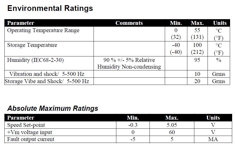
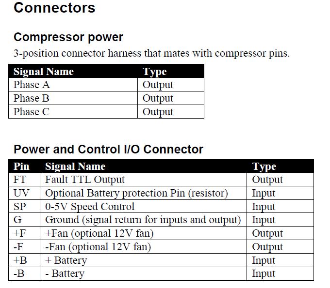
8 Compressor Controller Device Overview Features 4 poles sensor-less variable speed BLDC motor controller 325 W maximum output power VDC input range rpm speed V analog speed set input (resistor programmable for fixed speed) 0 to +55 C operating temperature Under/Over voltage shutdown (resistor programmable under voltage thresholds) Locked rotor detection Thermal shutdown for power devices Over current shutdown for power devices Low speed shutdown TTL Fault output LED fault indicator Fan output, 0.5A with voltage detection Reverse polarity protection Description The TH motor controller has been designed to provide efficient control and monitoring of a 4 pole 48VDC brushless/sensor-less hermetic TH compressor. The controller will provide a constant speed as specified by the speed command input ( RPM) unless one of the following limitations occurs: Power limitation, this limits the average power the drive puts into the motor. If the load requires more than 325 W into the motor, the controller will shutdown the motor The compressor on/off operation is controlled by 0V 5V analog input. For fixed speed applications a resistor can be installed between ground at the controller and the speed input. (see resistor selection chart) The controller is designed to work in ambient temperatures from 0 C (32 F) to +55 C (131 F) and presents several fault sensors to protect the module, the power supply and the compressor. Visual Fault information is available through an LED that is uniquely flashed for each fault condition. A TTL fault output is also available that is high when fault is active. Operation Analog Speed Control (default) A 0-5VDC non-isolated analog input can be used to control the motor speed, off / on operation. When the analog input is between 0.26 and 0.99V or greater than 4.75V the 7
9 compressor is off. When the analog input is between 0V and.25v, the compressor will run at a fixed speed of 3000 RPM. If the analog input is above 0.99V and below 4.75V the compressor will start and ramp up at a rate of 600 RPM per second to the commanded speed. The speed command is mapped to 1V is 1800 RPM and 4.75V is 4200 RPM. Once the motor begins to run it will require the input voltage to go lower than 0.8V or higher than 4.75V to stop the motor (hysteresis). The motor controller will run the motor at the set-point speed unless a voltage, current or power limitation is exceeded. Fixed Speed Control A fixed motor speed can be set through an external resistor connected between ground at the controller and the speed input. A switch in series with the resistor can be used to turn the motor on and off in this configuration. See speed resistor selection chart. Fault Detection The compressor is turned off when any of the faults described below are detected. Faults are indicated on the fault output pin and flashed on the LED. The fan output is disabled for all faults except motor faults where the fan output will continue to be active if the run command is present. Faults Motor Fault If the compressor fails to start the fault output will be activated and a motor fault will be indicated on the LED. The controller will delay for 60 seconds before attempting to restart. Also the compressor must maintain a minimum speed of 1500 RPM for proper lubrication. If the controller is unable maintain 1500 RPM it will turn the compressor off then set the fault output and display motor fault. The controller will delay for 60 seconds before attempting to restart. If a motor fault occurs and the controller is commanded to run the fan output will continue to be active during the 60 second fault timer. All other fault conditions the fan output will be disabled until the fault is cleared. Under/Over voltage - The controller will continuously monitor the input voltage, if the input voltage exceeds the upper or lower limits it will turn the compressor off and set the fault output and display the appropriate fault message on the LED. The controller will then delay for 60 seconds. After the delay the controller will wait for the input voltage to be within specifications, if the voltage is within specification the controller will turn off the fault indicators and attempt to restart the compressor. The voltage trip points are detailed below for each operating mode. Short-Circuit (motor-phase to phase) Current Detection The controller monitors the motor current and will turn the compressor off then set the fault output and display the appropriate fault message if the current exceeds an internal pre-determined current threshold. The controller will delay for 60 seconds before attempting to restart. The controller will attempt to start ten times. After the tenth cycle the controller will enter into a lockout state that requires a power cycle to clear the fault. 8
10 *** When Lock-out has occurred the controller will turn the Fault LED ON. It will not flash when the controller is in lockout. Power devices temperature above limit - if the power devices have exceeded there maximum operating temperature 80 C the controller will turn the compressor off then set the fault output and display the appropriate fault message. The controller will delay for 60 seconds. After the delay the controller will monitor the power device temperature and if it has fallen below 80 C (176 F) the controller will clear the fault indicators and attempt to restart the compressor. Fan Voltage Out of Tolerance The controller continuously monitors the fan voltage. If the fan voltage is outside of the specified region due to excessive load current the controller will turn the and fan output off and turn off the compressor. The controller will then set the fault output and display the appropriate fault message. The controller will delay for 60 seconds before attempting to turn the fan output on and restarting the compressor. General Hardware Error This error occurs when one or more of several conditions are present in the system. The system consists of two Controllers, if the communication between the controllers is lost this can cause the error. Other examples of what can cause this error include: a difference of measured voltages, if the microcontrollers are measuring different voltages at the same point, and a difference in the current consumption measurements. LED Fault Indicator and Fault output The controller will signal a fault condition by outputting a logic high value on the fault output. The output is a TTL level signal capable of directly driving +/- 5mA. The controller will indicate a fault condition by flashing the fault LED. The Flashing pattern will be ¼ second on and ¼ second off for each count, then dwells 5 seconds and repeat until the fault(s) are cleared. Listed below are the fault codes. If the controller enters fault lockout from over current faults the LED will stay lit and not flash. 1 flash Motor Fault 2 flashes Under Voltage 3 flashes Over Voltage 4 flashes Over Temperature 5 flashes Over Current / Over Power 6 flashes Fan Voltage out of Tolerance 7 flashes General Hardware Error 8 flashes System Integrity Fault 9
11 FAN output Fan Power is on any time compressor is commanded to run and the fan fault is not active. The fan out is a current source. When the fan turns on it can support a current of 1A for 1 second. After the startup if the fan current exceeds 0.5A the controller will detect a voltage out of tolerance and then turn off the fan output and the compressor, set the fault output and display the appropriate fault message. The controller will delay for 60 seconds before attempting to turn on the fan output and restarting the compressor. Serial Port Diagnostic Messages The controller will report the model number on power up. The motor controller will report real time power device temperature, compressor speed, motor input voltage, compressor current and fault status on the serial port. Serial port configured for baud, 8 data bits, 1 stop bit, no parity, no flow control. Access to the connector will require the module to be disassembled. This port is not intended for end use. It is only present for debugging and testing during the development and testing of the controller. Engineering Specifications Operating Characteristics 10
12 11
13 12
14 13
15 14
16 Model No: TEC-7454 GENERAL DESCRIPTION The TEC is a single set point controller. It is specifically designed for application where in the compressor cuts off a set point and is restarted at temperature set point plus differential (P4 parameter). Additionally the TEC-7454 offers several protection features that are easily understood by the example in the instructions below. A numbers of parameters are displayed alphanumerically to set up the instruments for each specific application. INDEX Parameter Name P2 P3 P4 P5 P6 AL Ad E1 E2 E3 F1 F2 E4 LP FS EP Description Max High Temp limit & alarm. Min Low Temp limit & alarm. To set Differential (Hysteresis). Probe calibration. Time Delay (Relay restart after cutoff). Alarm - To activate Alarm Relay. Power On Time Delay For Alarm. Evaporator Fan feedback Enable/disable. Condenser Fan feedback Enable/disable. Compressor feedback Enable/disable. To set evaporator fan speed. To set condenser fan speed. Relay status on probe failure. Keypad Lock. Restore factory defaults. End Programming & Keypad functions. Key Introduction Operating messages LED Indications Technical Data Connection Diagram Panel cutout, dimensions & Bezel 15
17 Operating instructions of the Temp Controller Sr.No. Parameter Parameter setting method. Min Range Max Fact. Set 1 Set Point (SP) Press and hold set key for 2 seconds and release Function: To set the cut out point of the controller. Display will change to set value. The set point value can now be changed by using the UP/DOWN keys. After setting the desired value, press the set key and you will see - -" which confirms that the set point has been stored in memory. (P3+1) O C (P2-1) O C 27 O C 2 Press PRG key for 2 seconds and To set other parameters. Display will show P2 flash. To go to other parameters, use up / down keys. release. 2 P2 3 P3 the P2 press the set key. H (Message on Display) the P3 press the set key. L (Message on Display) Function: To set maximum allowable high temperature limit & alarm. Use UP/DOWN keys to set desired value. Once set at a particular value, this will not allow the set point to go above this value and below P3 setting. Example : Setting this parameter at 30 O C will not allow the set point to go above 30 O C. Also, if the temperature reaches 30 O C, the display will show Ht (High Temp.) indicating that the temperature has reached or gone above the value in this parameter and at this point the alarm relay will activate. Function: To set minimum allowable low temperature limit and alarm. Use UP/DOWN keys to set desired value. Once set at a particular value, this will not allow the set point to go below this value and above P2 setting. Example : Setting this parameter at 10 O C will not allow the set point to go below 10 O C. Also, if the temperature reaches 10 O C, the display will show Lt (Low Temp.) indicating that the temperature has reached or gone below the value in this parameter and at this point the alarm relay will activate. (SP+1) O C 50 O C 35 O C 10 O C (SP-1) O C 10 O C 4 P4 Function: To set the differential. 1 O C 10 O C 2 O C 16
18 5 P5 6 P6 the P4 press the set key. the P5 press the set key. the P6 press the set key. Use UP/DOWN keys to set desired value. Differential between cut out and cut in temperature can be set between 1OC to 10OC. Example : If the set point is set at 10 O C and differential is set at 2 O C, then when the system reaches 10 O C, the relay will cut out. Since the differential is 2, the relay will cut in (restart) at 12 O C (10 O C+2 O C). Function: To set probe calibration. -9 O C 10 O C 0 O C Use UP/DOWN keys to set desired value. In time it may be possible that the display may be offset by a degree or so. To compensate for this error, you may need to add or minus the degrees required to achieve the correct temperature. Example : The temperature on the display is 28 O C, whereas the actual temperature is 30 O C. You will need to set the P5 mode to 2, which means that once out of the programming the display will show the temperature 30 O C (28 O C + 2 O C). Function: To set time delay between relay restart time. Use UP/DOWN keys to set desired value. This parameter is used to protect the compressor from restarting in a short period of time and can be set between 0 to 99 minutes. Example : If this parameter is set at 3 minutes, the relay will cut off at the set temperature, but will not restart for a minimum of 3 minutes, even if the differential is achieved earlier. This parameter is good to protect the life of the compressor when there are power fluctuations and the compressor is switched off and on within a few seconds. 0Min 20Min 3Min 17
19 7 AL 8 Ad the AL press the set key. the Ad press the set key. Function: To activate alarm relay Use the UP/DOWN keys to set alarm on or off. Once set to on, the alarm relay will come on in case the temperature reaches or goes above or below the points set in parameter P2 & P3 and if the probe fails. 0 = De-activates alarm relay. 1 = Activates alarm relay. Function : To set power on time delay for alarm relay. Use up/down keys to set desired value. This parameter sets a time delay on power on for the alarm. 0 Min 30 Min 0 Min 9 E1 10 E2 11 E3 the E1 press the set key. the E2 press the set key. the E3 press the set key. Example : If this parameter is set to 20min once the unit is powered on the alarm relay will not activate for 20 minutes even if there is a fault. This is very useful to eliminate the nuisance alarm when a unit is switched on and the ambient is above the Max set limit in P2.This delay is applicable for High temperature alarms. Function : Evaporator Fan feedback Enable/disable. Use the UP/DOWN keys to set desired value. If set 0 = Evaporator Fan feedback sensing is Disabled. 1 = Evaporator Fan feedback sensing is Enabled. Function : Condenser Fan feedback Enable/disable. Use the UP/DOWN keys to set desired value. If set 0 = Condenser Fan feedback sensing Disable. 1 = Condenser Fan feedback sensing is Enable. Function : Compressor Fan feedback Enable/disable. Use the UP/DOWN keys to set desired value. If set 0 = Compressor F/B is disabled. 1 = Compressor F/B is enabled. (Auto Reset) 2 = Compressor F/B is enabled. (Manual reset, 3 retrials in 1 hour.) F1 Function : To set evaporator fan speed
20 7 AL Function: To activate alarm relay the F1 press the set key. Use the UP/DOWN keys to set desired value. Example : If this parameter is set to 99%. Evap. fan will run at 99% speed. 13 F2 14 E4 15 LP the F2 press the set key. the E4 press the set key. the LP press the set key. Function : To set condenser fan speed Use the UP/DOWN keys to set desired value. Example : If this parameter is set to 99%. Condenser fan will run at 99% speed. Function : Relay status on Probe Failure Use the UP/DOWN keys to set desired value. When set to 0 the relay status is ON. When set to 1, the compressor performs a duty cycle of 10 minutes ON and 4 minutes OFF. When set to 2 the relay status is OFF. Function : To lock keypad Use up/down keys to set desired value. This Parameter can lock the keypad so that tampering is not possible by by-standers. 0 = keypad unlocked 1 = keypad locked When locked all parameters can only be viewed, but not modified. 16 FS the FS press the set key. Function : To restore default settings of the controller. When set to 1 all parameters are programmed to factory values. Useful to debug setting related problems EP To end programming press the set key. Function : To end programming. Once the set key is pressed, the control goes into the normal mode and displays the temperature and all settings are recorded. 19
21 Key Introduction : Down/prg Key Used to enter into the program mode. Used in program mode to decrement parameter value. UP Key Used in program mode to increment parameter value. SET Key In program mode used to set the changed value of parameter. RST RST This key is used to reset any Manual faults present for Controller ( Compressor Feedback.) This key will reset the alarm relay. Operating messages and Icon Status Message Description Ht Lt PF EF High temperature alarm for Room.Means room temperature is above the set value of Ht parameter. Low temperature alarm for Room.Means room temperature is below the set value of Lt parameter. Room,Supply temperature or Supply temperature fail means sensor not connected or out of range. Range Temperature : 0 to 70 O C Evaporator Fan Feedback Fault. CF Condenser Fan Feedback Fault. FF Compressor Feedback Fault. LED Indications : LED LED Status Description ON Evaporator Fan is ON. FLASHING Evaporator Fan is in Power ON time delay. OFF ON OFF ON Evaporator Fan is OFF Condenser Fan is ON. Condenser Fan is OFF. Compressor is ON. FLASHING Compressor is in time delay. OFF ON ON OFF Compressor is OFF. Alarm relay is ON due to faults like Room Sensor, Room High Temperature Fault, Room Low Temperature Fault, Compressor Feedback Fault, Evaporator/Condenser Feedback Fault. Keypad is Locked. Keypad is Unlocked. 20
22 TECHNICAL DATA Housing : Black ABS plastic. Front cover : Polycarbonate plastic & ABS plastic Dimensions : Front - 75 X 32.5 mm, depth 71mm. Panel Cutout : 29 X 71mm Mounting : Flush panel mounting with bracket. Front protection : I.P65. Connections : Mini-fit type connector. Display : 2 X 14.2 mm (0.56") LED. Data storage : Non-volatile EEPROM memory Power input : 48Vdc. Operating temp. : 5 O C to 50 O C(non-condensing). Output : Cond. & Evap. Fan : 48VDC,1A Max. Relay1 : 8(3)A/250Vac Alarm : 5A/250Vac Storage temp : -20 O C to 70 O C(non-condensing). Input : NTC probe, SZ-N75. Range : 0 O C to 50 O C Resolution : 1 O C. Accuracy : +/- 1 O C. Probe tolerance at 25OC : +/- 0.3 O C. Pass Word protected 21

23 CONNECTION DIAGRAM : TEC-7454 Wiring Diagram EW CW CY EY C2 FT Yellow Yellow White White Green Temp. Sensor B +B C1 EY EW Grey Grey -B +B CY CW FT SP G FT UV SP G +F -F +B -B Controller-Compressor Evap. Fan Cond. Fan 48VDC +B -B Red Black *All Connecting wires to respective colors should be same color 22
24 Contact Details; Tecumseh Products India Pvt. Ltd. Plant & Regd. Office: Balanagar Township, Hyderabad (A,P,) India Tel: /94 Info@tecumsehindia.com Customer Care Hotline No Mail ID customercare.india@tecumseh.com Tecumseh Products India Pvt. Ltd. 38 KM Stone, Delhi Mathura Road, Ballabgarh, Harayana , India. Tel: Direct:
MasterFlux 48V Cascade BLDC Motor Controller Product Specification 030F0137
 MasterFlux 48V Cascade BLDC Motor Controller Product Specification 030F0137 Revision History Page 1 of 11 Date ECN Rev Description By 09/01/10 EC34869 A Initial Release D. Stahl 07/14/11 EC39745 B Updated
Sierra Dual 24 Volt Brushless DC Motor Controller Product Specification. Assembly 025F0348
 Sierra Dual 24 Volt Brushless DC Motor Controller Product Specification Assembly Revision History ECN # Date Rev Description By EC77363 03/15/17 A Initial Release K. Jones EC81620 11/15/17 B Added Agency
4-step Chiller and Heat Pump Controller
 4-step Chiller and Heat Pump Controller Technical Data Sheet GENERAL DESCRIPTION MODELS CODE MODEL DESCRIPTION MW324000 ECH 420 HEAT PUMP WITH 4 STEPS/ 2 CIRCUITS + MODBUS MW324005 ECH 420/V WITH SCREW
Brushless DC Motor Controller Product Specification Assembly 025F0219
 Product Specification Assembly Revision History ECN # Date Rev Description By EC46310 6/14/12 A Initial Release Z. Sheu EC63683 01/27/15 B Correct interface connector part number D. Stahl EC81620 11/15/17
MAXDTC-BT Family User Manual
 MAXDTC-BT Family User Manual Description The MAXDTC-BT is a fully programmable industrial temperature controller. The controller is configurable and monitorable thru a Bluetooth connection from your Android
Brushless DC Motor Controller Product Specification Assembly 025F0200
 Product Specification Assembly 025F0200 Revision History ECN # Date Rev Description By EC40382 071811 A Initial Release D. Stahl EC81620 11/15/17 B Added Agency Approval S. Lavey Page 1 of 11 Table Of
Brushless DC Motor Controller Product Specification Assembly 025F0095
 Product Specification Assembly 025F0095 Revision History ECN # Date Rev Description By N/A 1/23/06 1 First issue A. Meeuwsen N/A 2/07/06 2 Added content A. Meeuwsen 06008 3/13/06 A Release for document
Installation & Operation and Maintenance
 Gas Safety Products Dual Current Monitor Installation & Operation and Maintenance Read these instructions carefully before operating or servicing Rev: 01 Date: 12-02-18 1 CONTENTS Chapter Content Page
EWPC 901/A rel. 6/96 ing
 EWPC 91A rel. 696 ing temperature controller with alarm output WHAT IT IS The EWPC 91A is a temperature controller specifically designed for refrigeration applications. The instrument includes a 1 Vdc
Measure & Control Temperature & CO2 levels with analog & digital I/O
 MADE IN OZ HTC-DIGITAL-LCD PROGRAMMABLE TEMPERATURE CONTROLLER c/w YEARLY PROGRAMMABLE TIME SWITCH COMPATIBLE WITH A WIDE RANGE OF SENSORS ROOM O/A WALL DUCT PIPE Use Features Measure & Control Temperature
Quantum III. Compact DC Drive Package. Slitter DC Drive Package. Quantum III
 Compact DC Drive Package The delivers a DC drive package that integrates the intelligence of the Mentor II with a space saving design that incorporates many accessories typically required in the North
BD Controller 101N07xx Series 24 V DC with Tool4Cool LabEdition software Operating Instructions
 MAKING MODERN LIVING POSSIBLE with Tool4Cool LabEdition software Operating Instructions 2 DEHC.PS.100.I.02 1.0 Introduction 1.1 Applications... 5 1.2 Capability... 5 1.3 Functions... 5 1.4 Programming
Tempco Instruction Manual
 Tempco Instruction Manual 1/16 DIN Solid State Temperature Controller Relay Output Solid State Output For Heating Model Numbers: TEC-901, TEC-902, TEC-905 Temperature controls in this series are designed
CHAPTER 1. Introduction Introduction 3
 Technical & User Manual Weight Indicator: SMIT-3015 Manufactured By: Samyak Instrumentation Pvt.Ltd. F-4, Memnagar Complex, Opp.Petrol Pump, Memnagar Village, Ahmedabad, India-380052. Phone: +91-79-27495500/5600,
SmartFan Fusion-4. Speed Control and Alarm for DC Fans CONTROL RESOURCES INCORPORATED. The driving force of motor control & electronics cooling.
 SmartFan Fusion-4 Speed Control and Alarm for DC Fans The driving force of motor control & electronics cooling. P/N FUS300-F DC Controls SmartFan Fusion-4 is a digital fan speed control and alarm that
Series SD-3PB Digital THERMOSTAT + TIMER
 SD-3PB Thermostat and Interval Timer in one Unit. This microcomputer based controller consists of two sections: The Digital Timer and Digital Thermostat, working together to control the power switched
USER'S GUIDE BARD-LINK TM LC /LC SOLID STATE DUAL UNIT LEAD/LAG CONTROLLER & TEC-EYE HAND-HELD DIAGNOSTIC TOOL
 USER'S GUIDE BARD-LINK TM LC1000-100/LC1500-100 SOLID STATE DUAL UNIT LEAD/LAG CONTROLLER & TEC-EYE HAND-HELD DIAGNOSTIC TOOL Bard Manufacturing Company, Inc. Bryan, Ohio 43506 Since 1914...Moving ahead,
AE R6 July 2018 Electronic Unit Controller
 July 2018 Electronic Unit Controller TABLE OF CONTENTS Safety... 3 Safety Instructions... 3 Safety Icon Explanation... 3 Instructions Pertaining to Risk of Electrical Shock, Fire, or Injury to Persons...
OEM. Room unit QAA822 with2- wire interface. Building Technologies CLIMATIX TM. For use with Climatix controllers
 OEM CLIMATIX TM Room unit QAA822 with2- wire interface For use with Climatix controllers Remote control of air conditioning unit Mandík Measurement of the room temperature Buttons for starting, setting
ARCTIC AIR DC OLED. Digital Control Operations Manual
 ARCTIC AIR DC OLED Digital Control Operations Manual Micro Air Corporation Phone (609) 259-2636 124 Route 526 WWW.Microair.net Allentown NJ 08501 Fax (609) 259-6601 Before you start: 1. Applying power:
MC Series Drives. Flexible, simple, rugged, robust!
 Drives Flexible, simple, rugged, robust! Our promise Commitment to Price Leadership Price leadership is serious business. It takes continuous life cycle management to make price leadership a sustainable
Microprocessor based Temperature / CO2 Controller c/w 365 Day Time Switch & Modbus Communication.
 HTC-DIGITAL-LCD Microprocessor based Temperature / CO2 Controller c/w 365 Day Time Switch & Modbus Communication. Features Use Australian Made and designed LCD 2 X 16 Character Backlit Display Five Programmable
ADC7520 SERIES. 1600W Battery Chargers and Power Supplies
 ADC7520 SERIES 1600W Battery Chargers and Power Supplies Wide output adjustment range 0 72VDC Analog control by external 0-5VDC voltage Temp.comp charging, sense as on option Power fail relay alarm Master-Slave
CDD4 Duct Carbon Dioxide Transmitter
 Drill or punch a 1-1/8 or 1-1/4 hole in the duct at the preferred location and insert the probe into the hole to mark the enclosure mounting holes. Remove the unit and drill the four mounting holes. Clean
Model HM-535 Power Supply Installation and Service Instructions
 Model HM-535 Power Supply Installation and Service Instructions 430-535 0104 2004 Heritage MedCall, Inc SENTRY INSTALLATION & SERVICE INSTRUCTIONS POWER SUPPLY UNIT Model HM-535 IMPORTANT SAFETY INSTRUCTIONS
lnvertek Drives.com ct,ve ELECTRICAL SUPPLIERS LTD
 lnvertek Drives.com ft ct,ve ELECTRICAL SUPPLIERS LTD OptidriveE2 Technical Product Guide 1.1 OVERVIEW Range IP20 IP66X (NON SWITCHED) IP66Y (SWITCHED) Supply Voltage Range Power Range 110 115 + / 10%
RT4F-120V/20A-WAC RECTIFIER
 The RT4F-120V/20A-WAC is a switched mode rectifier/charger module designed to provide up to 20A of output current into a 120V nominal system. This charger has been designed for use in conjunction with
pco 3 Controller User Manual ASPX Digital Scroll, Air Packaged Chiller For Version MCDSV_A02
 pco 3 Controller User Manual ASPX Digital Scroll, Air Packaged Chiller For Version MCDSV_A02 pco 3 Controller User Manual Introduction The Airstack Chiller is a modular air-cooled chiller composed of
UDC 1000 and UDC 1500 MICRO-PRO SERIES UNIVERSAL DIGITAL CONTROLLERS
 UDC 1000 and UDC 1500 MICRO-PRO SERIES UNIVERSAL DIGITAL CONTROLLERS EN0I-6041 12/99 PRODUCT SPECIFICATION SHEET OVERVIEW The UDC 1000 and UDC 1500 are microprocessor-based 1/16 DIN and 1/8 DIN controllers
MAINTENANCE MANUAL. EDACS REDUNDANT POWER SUPPLY SYSTEM 350A1441P1 and P2 POWER MODULE CHASSIS 350A1441P3, P4, AND P5 POWER MODULES TABLE OF CONTENTS
 MAINTENANCE MANUAL EDACS REDUNDANT POWER SUPPLY SYSTEM 350A1441P1 and P2 POWER MODULE CHASSIS 350A1441P3, P4, AND P5 POWER MODULES TABLE OF CONTENTS SPECIFICATIONS*... 2 INTRODUCTION... 3 DESCRIPTION...
Semi flush-mounted room temperature controllers with LCD
 s 3 077 RDD310 RDE410 Semi flush-mounted room temperature controllers with LCD For heating systems RDD310 RDE410 RDD310 and RDE410 features: Operating voltage AC 230 V 2-position control with On / Off
FCU (FREE COOLING UNIT)
") FCU (FREE COOLING UNIT) FCU reduces the AC running hours on the telecom site Controller Features: Can control upto two AC and one free cooling unit Temperature control Humidity sensor Structural Features:
FCU (FREE COOLING UNIT) FCU reduces the AC running hours on the telecom site Controller Features: Can control upto two AC and one free cooling unit Temperature control Humidity sensor Structural Features:
Multi Units Humidity/Temperature Transmitter. HygroViewer Model JW300 User Manual
 Multi Units Humidity/Temperature Transmitter HygroViewer Model JW300 User Manual 1. Electrical Wired & Installation The power cord is a one-meter length, 22 AWG, 7 different colors for recognition. Please
SmartFan Vortex. I2C Speed Control for 12 VDC Fans CONTROL RESOURCES INCORPORATED. The driving force of motor control & electronics cooling.
 The driving force of motor control & electronics cooling. SmartFan Vortex I2C Speed Control for 12 VDC Fans DC Controls P/N VOR5I400F SmartFan Vortex is an I2C fan speed control and alarm designed for
SS2200 Remote Controller
 SS2200 Remote Controller General Purpose, DC Voltage General The SS2200 Remote Controller is a microprocessor-based programmable controller specifically designed to control single line and dual line centralized
IntesisBox. v.0.1. User Manual Issue Date: 12/2017 r1.3 EN
 IntesisBox HS-RC-MBS-1 v.0.1 Modbus RTU (EIA-485) Interface for Hisense air conditioners. Compatible with commercial line of air conditioners commercialized by Hisense. User Manual Issue Date: 12/2017
INSTRUCTION MANUAL STATION CONTROLLER SC1000 MOTOR PROTECTION ELECTRONICS, INC.
 INSTRUCTION MANUAL STATION CONTROLLER SC1000 MOTOR PROTECTION ELECTRONICS, INC. 2464 Vulcan Road, Apopka, Florida 32703 Phone: (407) 299-3825 Fax: (407) 294-9435 Revision Date: 9-11-08 Applications: Simplex,
Semi flush-mounted room temperature controllers with LCD
 s 3 077 RDD310 RDE410 Semi flush-mounted room temperature controllers with LCD For heating systems RDD310 RDE410 RDD310 and RDE410 features: Operating voltage AC 230 V 2-position control with On / Off
Sierra 80 Volt Brushless DC Motor Controller Product Specification
 Sierra 80 Volt Brushless DC Motor Controller Product Specification Assembly 025F0135 600A0588 Rev. B January 29, 2010 025F0135 Brushless DC Motor Controller Page 1 Revision History ECN # Date Rev Description
FX 2 Instruction Manual
 FX 2 Instruction Manual Climma Compact Version Annapolis MD USA 301 352 6962 info@veco-na.com Introduction: The FX2-DX digital controller operates onboard air conditioning equipment to provide room temperature
UCU Room Display. Operation Modes. Features. Applications DATASHEET
 DATASHEET UCU Room Display The UCU Room Display provides dedicated visually appealing Room Control display for use with UCU10FC/K Unitary Controller. The display allows the user to view and adjust selected
FC-DIN DIN-Rail Mount Fan Speed Controller
 Page 1 of 7 FC-DIN DIN-Rail Mount Fan Speed Controller Features: Benefits: Volume or velocity reduction Suitable for supply & extract systems Minimum and maximum speed adjustment DIN-Rail mountable Configurable
TECHNICAL MANUAL WATER 300 C 5300 CV/06-00 GB
 T E C H N I C A L M A N U A L TECHNICAL MANUAL C 5300 CV/06-00 GB GB The information contained in this document may be modified without prior notice and is in no way binding, even implicitly, for CLIMAVENETA.
UNIT CONTROLLER 7 (UC7) Operation & Installation. Hydronic Units
 Operation & Installation. Hydronic Units") UNIT CONTROLLER 7 (UC7) Operation & Installation Hydronic Units Date: 1 November 2012 Issue: 5 Page 1 of 17 Contents 1. Connections, hydronic unit... 3 2. Functions assigned to SSR1, SSR2 and AUX... 3
UNIT CONTROLLER 7 (UC7) Operation & Installation Hydronic Units Date: 1 November 2012 Issue: 5 Page 1 of 17 Contents 1. Connections, hydronic unit... 3 2. Functions assigned to SSR1, SSR2 and AUX... 3
Temperature controller Ducted systems
 2 725 Temperature controller Ducted systems Standard model without zoning functions RRV851 Multifunctional controller used for central control of ducted HVAC systems in combination with a QAX850 master
Trident and Trident X2 Digital Process and Temperature Panel Meter
 Sign In New User ISO 9001:2008 Certified Quality System Home Products Online Tools Videos Downloads About Us Store Contact Policies Trident and Trident X2 Digital Process and Temperature Panel Meter Products
RT4F-110V/25A RECTIFIER
 The RT4F-110V/25A is a hot-pluggable switched mode rectifier (SMR) module designed to provide up to 25A of output current into a 110V nominal system. Examples of such systems are 60 cells lead acid (136V
GFC114. Low Power Flow Computer FEATURES
 Low Power Flow Computer FEATURES l UNIVERSAL INPUT, 5 khz, CAN POWER THE l SIMPLIFIED MENUS AND PROGRAMMING l NO NEED OF AMPLIFIERS OR LINEARIZERS l SEVEN DIGIT RATE WITH PROGRAMMABLE DECIMAL PLACES l
RT4B-110V/12A RECTIFIER
 The RT4B-110V/12A is a switched mode rectifier (SMR) module designed to provide up to 12A of output current into a 110V nominal system. It can be used with or without a cooling fan. With a fan it runs
Instruction Manual CTC-1
 Troubleshooting & Specs CTC-1 Amps / Volts requirements Min / Max operating temperature Min / Max operating Humidity Temperature Measurement range Temperature Accuracy CO2 sensor type CO2 Measurement range
SmartFan Cirrus-9. Speed Control and Alarm for 4-Wire Fans CONTROL RESOURCES INCORPORATED. The driving force of motor control & electronics cooling.
 SmartFan Cirrus-9 Speed Control and larm for 4-Wire Fans The driving force of motor control & electronics cooling. P/N 4WR9C00-F DC Controls SmartFan Cirrus-9 is a digital fan speed control and alarm that
INSTALLATION DKM-409 NETWORK ANALYSER WITH HARMONIC MEASUREMENT AND SCOPEMETER. Before installation:
 DKM-409 NETWORK ANALYSER WITH HARMONIC MEASUREMENT AND SCOPEMETER The DKM-409 is a precision instrument designed for displaying various AC parameters in 3-phase distribution panels. Thanks to its isolated
Mini Design Inverter. For applications which need tiny installation space. HNC Electric Limited
 H V 90 Mini Design Inverter For applications which need tiny installation space HNC Electric Limited 07.8 About HNC Electric HNC Electric is an automation & drive focused global company, providing global
This document describes the features and functional specifications of the ECONO3 air conditioner controller.
 TITLE : FUNCTIONAL SPECIFICATION FOR ECONO3 COOL REV : 01 DATE : MARCH 13, 2001. 1. INTRODUCTION 1.1 Scope of Document This document describes the features and functional specifications of the ECONO3 air
COMFORT CONTROL CENTER SERVICE INSTRUCTIONS
 USA SERVICE OFFICE Dometic Corporation 2320 Industrial Parkway Elkhart, IN 46516 574-294-2511 CANADA Dometic Corporation 46 Zatonski, Unit 3 Brantford, ON N3T 5L8 CANADA 519-720-9578 For Service Center
DPM Digital DC Power Meter with Data logging capability. User Manual
 DPM-3232 Digital DC Power Meter with Data logging capability User Manual Introduction As a digital DC power meter, it measures the real time DC Voltage (5-60V), DC Current (0-60A), Watt, and it also displays
D115 The Fast Optimal Servo Amplifier For Brush, Brushless, Voice Coil Servo Motors
 D115 The Fast Optimal Servo Amplifier For Brush, Brushless, Voice Coil Servo Motors Ron Boe 5/15/2014 This user guide details the servo drives capabilities and physical interfaces. Users will be able to
Series B9 and C9 Electronic Metering Pumps. Instruction Manual. Manual No : 1796 Rev. : D Rev. Date : 11/2015
 Series B9 and C9 Electronic Metering Pumps Manual No : 1796 Rev. : D Rev. Date : 11/2015 sales@novatech-usa.com www.novatech-usa.com Tel: (866) 433-6682 Fax: (866) 433-6684 Tel: (281) 359-8538 Fax: (281)
RTD-W Installation Instructions
 RTD-W Installation Instructions 0V +V POWER 15-24VDC 0V S1 S2 S3 0V S4 S5 S6 English RTD-W Installation Instructions 100.00 RTD-W Control Interface realtime Control Systems 24VAC/30VDC, 1A REMC P1 P2 RS485
KOBOLD TDA Series Digital Temperature Transmitter
 KOBOLD TDA Series Digital Temperature Transmitter TDA-15 Series User Instructions KOBOLD Instruments Inc. 1801 Parkway View Drive Pittsburgh, PA 15205 Phone (412) 788-2830 Fax (412)-788-4890 www.koboldusa.com
12-36 VDC/12-24 VAC Power Option 4-Digit Display, 0.56 (14.2 mm) or 1.20 (30.5 mm)
 or 1.20 (30.5 mm)") 4-20 ma & Relay Output Features 4-20 ma, ± 10 V, TC & RTD Inputs 12-36 VDC/12-24 VAC Power Option 4-Digit Display, 0.56 (14.2 mm) or 1.20 (30.5 mm) 24 VDC @ 200 ma Transmitter Power Supply Options Type
4-20 ma & Relay Output Features 4-20 ma, ± 10 V, TC & RTD Inputs 12-36 VDC/12-24 VAC Power Option 4-Digit Display, 0.56 (14.2 mm) or 1.20 (30.5 mm) 24 VDC @ 200 ma Transmitter Power Supply Options Type
CDD Carbon Dioxide Transmitter
 Introduction The OSA CO2 transmitter uses Infrared Technology to monitor CO2 levels within a range of 0 2000 ppm and outputs a linear 4-20 ma or 0-5/0-10 Vdc signal. The enclosure is designed to operate
TEMPERATURE CONTROLLER 2 HEAT/ 2 COOL with Digital Room Temperature Display. Made in Australia 100% Australian Owned Company
 TEMPERATURE CONTROLLER 2 HEAT/ 2 COOL with Digital Room Temperature Display HTC 5 Features Australian Made and designed Power can be either 24V or 240V AC 10 Amp (Resistive) Potential free relay contacts
RCF-230CAD. Room controller with communication for fancoil applications with two analogue V DC outputs
 revision 04 2016 RCF-230CAD Room controller with communication for fancoil applications with two analogue 0...10 V DC outputs Intended to control heating and/or cooling in 2- or 4-pipe installations. Setpoint
2 Table of Contents 1. TABLE OF CONTENTS. 1. Table of Contents Introduction Wiring Diagram Terminals Review...
 TPR-6 Temperature Protection Relay Instruction Manual Ver. June 1 st 2010 2 Table of Contents 1. TABLE OF CONTENTS 1. Table of Contents... 2 2. Introduction... 3 3. Wiring Diagram... 5 4. Terminals Review...
CHAPTER MAINTENANCE AND TROUBLESHOOTING. In This Chapter... Maintenance and Inspection Troubleshooting...6 3
 CHAPTER MAINTENANCE AND 6 TROUBLESHOOTING In This Chapter... Maintenance and Inspection..........................6 2 Monthly Inspection...................................6 2 Annual Inspection....................................6
PDS100 Programmable Dispensing System SAFETY INSTRUCTIONS
 PDS100 Programmable Dispensing System INSTRUCTION MANUAL SAFETY INSTRUCTIONS Before using any Fluid Metering, Inc. product read the following safety instructions as well as specific product specifications
Masibus Automation And Instrumentation Pvt. Ltd.
 Operator s Manual DIGITAL CONTROLLER 5006H Masibus Automation And Instrumentation Pvt. Ltd. B/30, GIDC Electronics Estate, Sector-25, Gandhinagar-382044, Gujarat, India Ph: 91 79 23287275-79 Fax: 91 79
TOXALERT MODEL AIR 2000
 TOXALERT MODEL AIR 2000 NOTE: Toxalert s Model GVU-CO 2 Sensor is the same as the Air2000R. Microprocessor-based, Infrared Environmental CO 2 Sensor OPERATOR S MANUAL TOXALERT TM INTERNATIONAL INC. P.O.
ph/orp 300 (Cat. No ) MICROCOMPUTER BASED OPERATION MANUAL ph /ORP/ Temperature CONTROLLER Phone: , Fax:
 MICROCOMPUTER BASED OPERATION MANUAL ph /ORP/ Temperature CONTROLLER Phone: , Fax:") OPERATION MANUAL /ORP 300 (Cat. No. 0580212) MICROCOMPUTER BASED /ORP/ Temperature CONTROLLER 625 East Bunker CT, Vernon Hills, IL 60061-1844 Phone: 800-32-4340, Fax: 847-247-2929 E-mail: info@coleparmer.com,
OPERATION MANUAL /ORP 300 (Cat. No. 0580212) MICROCOMPUTER BASED /ORP/ Temperature CONTROLLER 625 East Bunker CT, Vernon Hills, IL 60061-1844 Phone: 800-32-4340, Fax: 847-247-2929 E-mail: info@coleparmer.com,
Available with actuator function: POWER OPEN - POWER CLOSE FAILSAFE MODULATING FAILSAFE MODULATING. Overview
 Feature rich J+J multi-voltage smart electric actuator with LED status light and function conversion kits. J3C-S20 Overview The J3C-S20 multi-voltage smart electric valve actuator from the European electric
vacon nx ac drives brake chopper unit (bcu) application user s manual
 application user s manual") vacon nx ac drives brake chopper unit (bcu) application user s manual 2 vacon Introduction Vacon Brake Chopper Unit application INDEX Document code: DPD01565A Software code: ABFIFF01V113 Date: 27.3.2014
vacon nx ac drives brake chopper unit (bcu) application user s manual 2 vacon Introduction Vacon Brake Chopper Unit application INDEX Document code: DPD01565A Software code: ABFIFF01V113 Date: 27.3.2014
isma-b-fcu FCU Hardware User Manual Global Control 5 Sp. z o.o. Warsaw, Poland
 isma-b-fcu User Manual FCU Hardware Global Control 5 Sp. z o.o. Warsaw, Poland www.gc5.pl Table of contents 1 Introduction 3 1.1 Document change log 3 1.2 Safety rules 3 1.3 Technical specifications 4
manufactured by SF8150-ZIF14
 manufactured by manufactured by SF8150- ZIF14 Butterfly packaged laser diode controller Datasheet & Users Manual Before powering on your driver, read this manual thoroughly. If you have any doubt or suggestion,
Compressor Controller MAM 890
 Compressor Controller MAM 890 OPERATION MANUAL Revision 1.0 04.08.2017 Notice Please read all the operation manual before operating the set and keep this manual for further reference. Installation of MAM
Before powering on your driver, read this manual thoroughly. If you have any doubt or suggestion, please do not hesitate to contact us!
 Laser diode driver Datasheet & UserManual Before powering on your driver, read this manual thoroughly. If you have any doubt or suggestion, please do not hesitate to contact us!, 37 Sedova St, Off 209,
ETM MD100 Drive System 1/2HP (370W) User Manual. Table of Contents. Drive Features
 User Manual. Table of Contents. Drive Features") Table of Contents Drive Features... 1 Drive Specifications... 2 Certifications... 3 Installation - Drive Dimensions... 3 Motor Dimensions (mm)... 4 Drive Mounting... 4 Wiring... 5 I/O Terminals... 9 Menu...
Table of Contents Drive Features... 1 Drive Specifications... 2 Certifications... 3 Installation - Drive Dimensions... 3 Motor Dimensions (mm)... 4 Drive Mounting... 4 Wiring... 5 I/O Terminals... 9 Menu...
RT4F-48V/50A-WAC RECTIFIER
 The RT4F-48V/50A-WAC is a switched mode rectifier (SMR) module designed to provide up to 58A of output current into a 48V nominal system, over a wide range of AC input voltage. This rectifier has been
INTRODUCING THE S V ADJUSTABLE SPEED DRIVE
 MOTORS & DRIVES ADJUSTABLE SPEED DRIVES (ASD) GROUP INTRODUCING THE S15 600 V ADJUSTABLE SPEED DRIVE Extreme Performance Micro-Drive - Heavy Duty, Compact, and Durable ASD SUPPORT NEWS: Toshiba s heavy
The PM1000 series is a universal 4 digit LED plug-on display for transmitters with 4-20mA 2 wire output and fitted with DIN43650 connector.
 PM1000 SERIES PLUG-ON DISPLAY BRIGHT LED DISPLAY INDICATION RANGE -999 TO +9999 FITS TO DIN 43650 CONNECTOR PLUG-ON TO ANY TRANSMITTER WITH 4-20MA OUTPUT EASY TO SCALE ON SITE ROBUST DESIGN SET POINT OPTION
Data sheet MK 20 GR. Customized solution or off-the-shelf: The choice is yours!
 Data sheet MK 20 GR Customized solution or off-the-shelf: The choice is yours! MK20-GR data sheet Looking for a quick and reliable solution? Then rely on our standard products: Our universal controls provide
User Manual. Solar Inverter for Water Pump
 User Manual Solar Inverter for Water Pump SP Revival Series Version: 1.2 Table Of Contents ABOUT THIS MANUAL... 1 Purpose... 1 Scope... 1 SAFETY INSTRUCTIONS... 1 Inspection... 1 Installation... 1 Operation...
Operation Manual CX20 1/8 DIN Microcomputer Based Conductivity/Resistivity Controller
 Operation Manual CX20 1/8 DIN Microcomputer Based Conductivity/Resistivity Controller 11751 Markon Drive Garden Grove, CA. 92841 U.S.A. pg. 1 CONTENTS GENERAL INTRODUCTION.....3 INITIAL INSPECTION......3
Optidrive Applications Support Library
 Optidrive Applications Support Library Application Note Title AN-ODE-3-038 Related Products Optidrive E3 Overview Level 3 Modbus RTU Control and Register Mapping 1 Fundamental - No previous experience
The IQ240 panel mount load cell indicator is a precision digital indicator for load cell and strain gauge applications.
 IQ240 Panel Mount Load Cell Indicator Data sheet English 1.01 Introduction The IQ240 panel mount load cell indicator is a precision digital indicator for load cell and strain gauge applications. The high
Dieter Wirth, Mess & Regeltechnik Neidlingen
 Dieter Wirth, Mess & Regeltechnik Neidlingen Temperature controller Mod. BI50, BT31/32 and BI500, BT310/320/321 Made in Germany contents BT series 1. General Description... 2 2. Operating modes... 2 3.
Service Bulletin SB685. Date: 8/18/2017 TriPac EVOLUTION Communications Update Bulletin Location: TSA Info Central\Service Bulletins
 Service Bulletin SB685 Date: 8/18/2017 Subject: TriPac EVOLUTION Communications Update Bulletin Location: TSA Info Central\Service Bulletins Units: All TriPac EVOLUTION Summary: This bulletin updates and
Operation Manual CX10 1/8 DIN Microcomputer Based Conductivity/Resistivity Controller
 Operation Manual CX10 1/8 DIN Microcomputer Based Conductivity/Resistivity Controller 11751 Markon Drive Garden Grove, CA. 92841 U.S.A. pg. 1 CONTENTS GENERAL INTRODUCTION.....3 INITIAL INSPECTION......3
PHASETRONICS. SCR Power Control Specialists. EP1 Series Power Control Single Phase SCR Amps OPERATION & SERVICE MANUAL
 PHASETRONICS Specialists EP1 Series Power Control Single Phase SCR 10-50 Amps OPERATION & SERVICE MANUAL Phasetronics, Inc. P.O. Box 5988 1600 Sunshine Drive Clearwater, FL 33765 (727)573-1900 FAX(727)573-1803
COND. A ENABLE RELAY CONTACT COOLA ENABLE 24 VAC. RATING IS 1 AMP COND. B ENABLE COOL B ENABLE.
 Factory Packaged Controls Coil Products Two Head Pressure Module Orion No.:OE370-23-HP2C 1 2 3 4 www.aaon.com www.orioncontrols.com Circuit A1 TRANSDUCER #1 Circuit A2 TRANSDUCER #2 Circuit B1 TRANSDUCER
INTRODUCTION. FX-1 Operations Manual. Standard Features. Optional Features. Read This Manual Completely Before Proceeding!
 INTRODUCTION The FX-1 Control is designed for use with all direct expansion, reverse cycle air conditioning systems. FX-1 has a universal power supply that operates on 115, 230, 50 or 60 Hz AC power. FX-
Brushless DC Motor Controller Specification Assembly 025A0053
 Brushless DC Motor Controller Specification Assembly 025A0053 600A0053 Rev. 2 July 28, 2004 025A0053 Brushless DC Motor Controller Data Sheet Page 1 Revision History Date Rev Description By 5/15/04 1 Initial
Soft Starter Remote Operator. Section 1.0 Introduction 1.1 Important user information General Manual description...2.
 Section 1.0 Introduction 1.1 Important user information... 2 1.2 General... 2 1.3 Manual description...2 Contents Section 2.0 Specification 2.1 General technical data...3 2.2 Dimensions...3 Section 3.0
Instruction Sheet Board Style Low Water Cutoff
 Instruction Sheet Board Style Low Water Cutoff 102-305 SUPERSEDES: REVISION E DATED December 12, 2007 #5401173-REV F PLANT ID 001-3902 US Patents 6,904,800, 7,243,540, and 7,317,993 Other Patents Pending
STRA-17 Room controller. Installation and maintenance manual. Content
 Content Installation preparations... Wiring diagram...3 Display handling...5 Technical data...6 Configuration...7 Operating modes...7 Controller modes...7 Activation operating modes...7 Control states...8
INTRINSICALLY SAFE DUPLEXER PROTECTION. ELECTRONICS, INC Vulcan Road Apopka, Florida MOTOR INSTRUCTION MANUAL
 INTRINSICALLY SAFE DUPLEXER INSTRUCTION MANUAL MOTOR PROTECTION ELECTRONICS, INC. 2464 Vulcan Road Apopka, Florida 32703 Phone: Website: (407) 299-3825 www.mpelectronics.com Operating Program Revision:
PLC-24V10AL(-PT/-TH) Quick Start Manual (Rev.1.10)
 Quick Start Manual (Rev.1.10)") TEC (Peltier) Controller PLC-24V10AL(-PT/-TH) Quick Start Manual (Rev.1.10) Thank you for purchasing the TEC (Peltier) Controller PLC-24V10AL. Read these operating instructions carefully to ensure effective
TEC (Peltier) Controller PLC-24V10AL(-PT/-TH) Quick Start Manual (Rev.1.10) Thank you for purchasing the TEC (Peltier) Controller PLC-24V10AL. Read these operating instructions carefully to ensure effective
IBM Symposium Data Center Cooling. EC Systems for HVAC architecture and Direct air Cabinet Cooling
 IBM Symposium 2008 Data Center Cooling EC Systems for HVAC architecture and Direct air Cabinet Cooling Presented by David J. Spofford Product Manager IT/Telecomm 1 Agenda Data Center trends for IT and
PART 1: GENERAL PART 2: PRODUCT. Effective: 12/29/10 Page 1 of 6 FECA-TE-104D
 Specification Number: 23 09 33 Product Name: FRENIC-Eco AC Drives for Variable Torque Fan & Pump Applications (1-125Hp at 208/230V and 1-900Hp at 460V) PART 1: GENERAL 1.01 SUMMARY A. This specification
1/32-DIN TEMPERATURE CONTROLLER INSTALLATION, WIRING AND OPERATION MANUAL FORM 3882
 1/32-DIN TEMPERATURE CONTROLLER INSTALLATION, WIRING AND OPERATION MANUAL FORM 3882 This manual is intended for use in support of installation, commissioning and configuration of the 1/32-DIN Temperature