TBox-Radio & WIRC photocell User manual
|
|
|
- Constance Harris
- 5 years ago
- Views:
Transcription
1 Kit TBox-Radio & WIRC photocells


 Power")
")
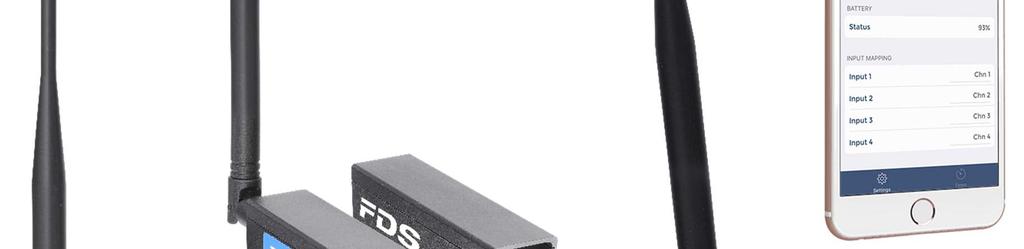
2 1. TBox-Radio 1.1 Appearance Radio antenna 2 x Photocells Jack Inputs Ext GPS antenna (TBox-4x only) 4 Group / ID LEDs Radio Config button 2 inputs LEDs Sync Jack RS232 Jack 2 manual input switches Mini GPS LED (TBox-4x) Power Status The TBox-Radio receives impulses from Wireless Infra-Red Cells (WIRC) photocell via the internal radio receiver.
3 1.2 Power ON/OFF The ON/OFF button switch has 3 functions: 1) Indicates the charge level of the battery Press and hold the ON/OFF button (front left) The 4 group/id LEDs (1 4) will illuminate to indicate the battery charge status 4 LED s ON green: 100 % 3 LED s ON green: 75% 2 LED s ON green: 50% 1 LED ON green: 25% 1 LED ON red: < 10% (TBox-Radio will only power on with external power applied) 2) Switch ON / OFF the TBox a) Press briefly the ON/OFF button (0.5s 1.5s) until the battery status is indicated on the LED s 1 4 b) Release the ON/OFF button and repress it within 1 second, and hold down until the 4 channels LEDs are ON, and the audible beep signal is emitted c) To switch OFF TBox-Radio simply repeat steps a and b 3) Activates the Bluetooth fast advertising mode Led Status of Power LED TBox-Radio USB Battery On/Off Yellow ON OFF connected Battery Charging Green ON OFF connected 100% charged Yellow blinking ON connected Battery Charging Green blinking ON connected 100% Charged Green blinking ON disconnected > 25% Red blinking ON disconnected Low battery
4 1.3 Timing Inputs The TBox-Radio model offers 2 hardware inputs and 4 wireless Radio-Inputs Manual Push Buttons (inputs 1 & 2) Jack-Mono photocell inputs (inputs 1 & 2) Working contact without potential (short-circuit) Input via Radio (see the description in chapter 1.4) Each press of the button, short-circuits on the Inputs or radio impulse are stored in the TBox- Radio memory, with associated date and time of impulse as CSV files. The user can configure a locking time using the TBox-Setup App. This facility allows the blocking of undesired impulses corresponding to the channel configured. E.g. to ignore multiple inputs from dirt or snow dust. 1.4 Wireless Configuration The TBox-Radio is configured and linked to WIRC photocells using two Parameters: Group (frequency parameter) ID (photocell identification) NOTE: TBox-Radio and WIRC photocells must be configured with an identical Group setting Group (Frequency parameter) EU / India We have the choice of selecting either from the 6 Group options below Group A, B, C, D: Wireless Transmission Distance: up to 2000m (clear line of sight) Each group uses ¼ of the full frequency band Min locking time of 200ms Group E, F: Wireless Transmission Distance: up to 5000m (clear line of sight) Each group uses the full frequency band Those groups limit the use of 2 WIRC only. Min locking time is longer: 500ms OFF: The radio transmission function is disabled. This mode is selected to save power when you prefer to connect TBox-Radio to photocells using a hard-wired solution rather than wireless.
5 1.4.2 Group (Frequency parameter) North America We have the choice of selecting either from the 8 Group options below Group A, B, C, D: Wireless Transmission Distance: up to 2000m (clear line of sight) Each group uses ¼ of the full frequency band Min locking time of 200ms Group E, F, G, H: Wireless Transmission Distance: up to 5000m (clear line of sight) Each group uses ¼ of the full frequency band Those groups limit the use of 2 WIRC only, Min locking time is longer: 500ms OFF: The radio transmission function is disabled. This mode is selected to save power when you prefer to connect TBox-Radio to photocells using a hard-wired solution rather than wireless. To configure your desired Group, press the Setup button The current Group selected is indicated by the (LED array A, B, C & D) Release and press the number of times you want to change the setting. Group LED A LED B LED C LED D A GREEN B GREEN GREEN C GREEN GREEN GREEN D GREEN GREEN GREEN GREEN E YELLOW F YELLOW YELLOW G (*) YELLOW YELLOW YELLOW H (*) YELLOW YELLOW YELLOW YELLOW OFF RED RED RED RED (*) only available for North America
6 1.4.3 ID (Photocell Identifier) Each impulse from a specific WIRC photocell, will be identified with the input number configured. TBox-Radio use a lookup table to link the photocell ID to a defined input (A to D). Thanks to the TBox-Setup App, where you can configure each specific Input value with a photocell ID. You can also manually change the Input attribution on the photocell itself provided a connection with the TBox-Radio is established (see chapter 2.4.3). NOTE: Each TBox-Radio radio input (A to D) must be configured with a different photocell ID to avoid data conflict. 1.5 Radio Communication The TBox-Radio will indicate each time an impulse is receive by flashing the relevant LED and giving an audible beep representing the configured ID. TBox-Radio will also identify in the same method when any photocell is misaligned. The communication works with acknowledge (ACK) signal to improve reliability. In case of perturbations or poor radio link the WIRC will make a few attempts to transmit the impulse. The pulse will only be lost if all attempts fail. 1.6 Time delay and precision In case of a good radio communication with no interferences, the time delay from the IR beam detection to the generation of a time event by the TBox-Radio will vary from 10ms to 150ms depending of the selected Group. In case of interferences this delay might reach a few seconds. However, whatever the delay value, the TBox-Radio takes it into account and generate a corrected time event with a precision of 1ms.
7 1.7 Mini-USB The Mini-USB connector has various functions including: 1.8 RS232 External power supply and battery charging COM port emulation for RS232 communication and data transfer - Real time of day in optional protocol formats (FDS, Alge, Seiko & TAG Heuer) - Configure the TBox-Radio options and parameters (with the app TBox-Setup ) - COM communication is only possible when the TBox-Radio is turned ON 2GB USB Flash Drive - All impulses are stored in a.csv file on the drive. A new file is created every time the TBox-Radio is switched ON - User needs to maintain sufficient memory availability to ensure storage of data - The space required for a competition of 1000 times is approximately 40 Kbytes - Flash Drive access is only possible when the TBox-Radio is turned OFF Jack-Stereo connection 3.5mm. In conjunction with the TBox-Setup, the protocol output can be configured by the user. FDS, Alge & TAG Heuer Time of day protocol Serial printer Display Output (FDS Protocol & TAG Heuer) 1: TBox-Radio TXD 2: TBox-Radio RXD 3: GND
8 1.9 In/Out Synchro Jack-4pin connection 2.5mm. Allows to synchronize the TBox-Radio with other timing systems 1: TBox-Radio +3.3V 2: TBox-Radio Sync In 3: TBox-Radio Sync Out 4: GND TBox-Radio Sync In Internal resistor to Vcc: 10 kohm Active state: Tie to Gnd, Sink 0.3mA Inactive state: Leave disconnected TBox-Radio Sync Out: Min ext. resistor to Vcc: 1kohm Max Vcc: 5V Active state: Tied to Gnd (1ms) Inactive state: Open circuit 1.10 Synchronization There are four different methods to synchronize the TBox. After power up, all 3 inputs LEDs will flash yellow if the TBox-Radio is not synchronized. a) Sync at Zero. This is the default synchro method. Once the TBox-Radio is switched ON, the first impulse will sync the internal time at Zero b) GPS Sync Only possible with models including GPS (TBox-4x) To start the GPS Sync, ensure TBox-Radio is powered off, hold down the button Input 1 whilst powering ON the TBox The sync will commence once the TBox-Radio receives sufficient GPS data Once synchronized, the internal clock drift is constantly compensated by GPS signals (if GPS coverage is maintained) c) External. Not yet implemented.
9 d) Sync via App 1.11 Bluetooth All synchro methods presented above can be controlled manually or automatically by our Timing Applications It is also possible to synchronize the TBox-Radio to a user define time of day, using one of the 2 inputs The TBox-Radio is able to be synchronize at the IPad time A Bluetooth connection can be established with compatible FDS timing or setup Apps. When not connected, a TBox-Radio advertise its presence continuously at a slow rate. Faster advertising rate can be momentary activated by a single and short press of the power button How to update the TBox-Radio Firmware To update the firmware, it is very easy. No software is required. a) Copy and paste the.bin file to the FDS-TBOX USB SD-Memory card Note that you should have only ONE firmware file on the menu. If you want to save the previous.bin files, create a sub-directory on the SD-Memory b) Ensure that you have no file call UPDATLOG.txt on the SD-Memory. If so delete it c) Disconnect your TBox-Radio from your PC d) Ensure that the TBox-Radio is OFF, then press and hold the ON/OFF button. The 4 Inputs LED s will switch Yellow then Green to indicate that the firmware updated successfully at which point you can release the ON/OFF button. e) A file UPDATLOG.txt is created on the SD-Memory to confirm that the new firmware is installed. f) Once the operation completed, it is advised to remove the.bin file from the root directory of the TBox-Radio SD card.
10 1.13 Technical specifications Radio Power Frequency : Europe India North America 100 mw MHz MHz MHz Operating temperature: -20 C to 50 C Precision diplayed 1/1 to 1/1000s Radio impulsion precision 1ms Time drift: 20 C; max 2.5ppm from -20 C to 70 C External power input: Battery: Autonomy: Bluetooth module: Dimension: Weight: USB compatible (5V +/- 10%) up to 1A LiPo 2200mAh 140 hours (GPS and Radio inactive) 70 hours (Radio active and GPS inactive) 45 hours (Radio and GPS active) BLE x80x31mm (without GPS) 124x86x31mm (with GPS) 180gr
 are a dual")

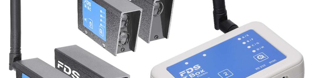
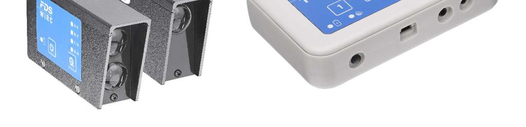
11 2. Photocells WIRC (Wireless Infra-Red Cells) 2.1 Appearance The Wireless Infra-Red Cells (WIRC) are a dual transmission photocell transmitting its impulse wirelessly via the internal radio transmitter and the 3.5mm Jack connector for wired installations.
 Switch ON OFF the WIRC a) Press and hold (1sec. 2secs.")

12 2.2 Power ON/OFF The ON/OFF button switch has 2 functions: 1) Battery status Press and hold the ON/OFF button (front left) LED green: > 60% LED yellow: > 20% LED red: < 20% 2) Switch ON OFF the WIRC a) Press and hold (1sec. 2secs.) the ON/OFF button until the battery LED status is Yellow b) Release the ON/OFF button and quickly repress it (within 1 second) and hold down until the battery Led status briefly flashes Yellow and then turns to Green. Switch OFF WIRC, simply repeat step a and b (at the end the LED is OFF) IR Transmitter IR Receiver ON / OFF Buttons Setting LED Status Mini-USB Status LED ON / OFF Setup button
13 2.3 Battery Status (IR Receiver) 1) Battery status whilst charging LED WIRC On/Off USB Battery Yellow OFF connected Battery Charging Green OFF connected 100% charged Yellow Flashing ON connected Battery Charging Green Flashing ON connected 100% Charged 2) Battery status with device ON and USB disconnected LED WIRC On/Off USB Battery Green ON disconnected 100% charged Yellow ON disconnected 20% - 60% charged Red ON disconnected 10% - 20% charged 3) Battery status with device OFF and USB disconnected Test by briefly pressing ON / OFF button LED WIRC On/Off USB Battery Green OFF disconnected 60% - 100% charged Yellow OFF disconnected 20% - 60% charged Red OFF disconnected <20% charged
14 2.4 Wireless Configuration The IR Receiver Cells and TBox-Radio are configured and linked using two Parameters Group (frequency parameter) ID (photocell identification use only on the TBox-Radio) NOTE: Each photocell working with TBox-Radio must be configured with the identical group setting Group (Frequency parameter) EU / India We have the choice of selecting either from the 6 Group options below Group A, B, C, D: Wireless Transmission Distance: up to 2000m (clear line of sight) Each group uses ¼ of the full frequency band Min locking time of 200ms Group E, F: Wireless Transmission Distance: up to 5000m (clear line of sight) Each group uses the full frequency band Those groups limit the use of 2 WIRC only Min locking time is longer: 500ms OFF: The radio transmission function is disabled. This mode is selected to save power when you prefer to connect TBox-Radio to photocells using a hard-wired solution rather than wireless.
15 2.4.2 Group (Frequency parameter) North America We have the choice of selecting either from the 8 Group options below Group A, B, C, D: Wireless Transmission Distance: up to 2000m (clear line of sight) Each group uses ¼ of the full frequency band Min locking time of 200ms Group E, F, G, H: Wireless Transmission Distance: up to 5000m (clear line of sight) Each group uses ¼ of the full frequency band Those groups limit the use of 2 WIRC only Min locking time is longer: 500ms OFF: The radio transmission function is disabled. This mode is selected to save power when you prefer to connect TBox-Radio to photocells using a hard-wired solution rather than wireless. To configure your desired Group, press the Setup button The current Group selected is indicated by the (LED array A, B, C & D) Release and press the number of times you want to change the setting. Group LED A LED B LED C LED D A GREEN B GREEN GREEN C GREEN GREEN GREEN D GREEN GREEN GREEN GREEN E YELLOW F YELLOW YELLOW G (*) YELLOW YELLOW YELLOW H (*) YELLOW YELLOW YELLOW YELLOW OFF RED RED RED RED (*) only available for North America
16 2.4.3 ID (Photocell Identifier) Each impulse from a specific WIRC photocell, will be identified with the input number configured. TBox-Radio use a lookup table to link the photocell ID to a defined input (A to D). Thanks to the TBox-Setup App, where you can configure each specific Input value with a photocell ID. You can also manually change the Input attribution on the photocell itself provided a connection with the TBox-Radio is established. NOTE: Each TBox-Radio radio input (A to D) must be configured with a different photocell ID to avoid data conflict. To set the ID form the WIRC, press the Setup button for 5 seconds until the audible beep is heard. Then Each time you press the button Setup, it will change the ID setting ID LED A LED B LED C LED D A GREEN B GREEN C GREEN D GREEN Once the desired ID is selected, press again the Setup button for 5 seconds until the audible beep is heard (this will activate the selection) If no confirmation is performed, the WIRC return to an idle state after a few seconds on inactivity.
 signal.")
17 2.5 Radio Communication The WIRC will indicate each time an impulse is transmitted, by flashing the relevant LED representing the configured ID (refer to upon table) The WIRC communication works with an acknowledge (ACK) signal. The photocells will resend their ID and impulse several times if no ACK is received and each time also flash the relevant LED representing the configured ID (refer to upon table) Red flash means no that no acknowledge has been received from the TBox. Flashing green means that pulse transition is completed with success. The ACK feature provides the user with a basic level of testing the positioning and communication between TBox-Radio and photocells. Many attempts may indicate that the communication is not very stable. A change of position of the photocell or the TBox-Radio (or just the antennas) may improve the communication. Radio transmissions cannot be 100% guaranteed. An unfavourable environment or an improper installation might lead to the loss of data. FDS cannot be held responsible. 2.6 Wired Connection The Jack connector on the rear of the WIRC photocell receiver enables a hard-wired connection to any timing device available today. The photocells simulate a short-cut between the 2 wires. The output impedance is 660 ohm, and the max voltage allowed on the output pin is 5.5V. 1: Output 2: NC 3: GND
18 2.7 USB The Mini-USB connector has various functions including: External power supply and battery charging Configure the WIRC photocell options and parameters (with the app TBox-Setup ) Update the Firmware 2.8 How to update the WIRC Firmware Updating the firmware is relatively simple. The software FdsFirmwareUpdate is requested a) Install the program FdsFirmwareUpdate on your computer b) Connect the USB cable to your PC and WIRC Photocell c) Run the program FdsFirmwareUpdate d) Select the COM Port e) Select the update file (.bin) f) Press Start on the program g) The photocell WIRC will update h) Once the update is finishing, remove USB cable and switch ON the photocell WIRC 2.9 Technical specifications Radio Power Frequency : Europe India North America 100 mw MHz MHz MHz Operating temperature: -20 C to 70 C Precision Min locking time (between two detections) External power input: Battery: Receiver Transmitter Autonomy: Receiver Transmitter Dimension: Weight (Tx / Rx): 1ms 200ms for Groups A-D; 500ms for Groups E-F USB compatible (5V +/- 10%) up to 1A LiPo 1700mAh LiPo 1700mAh 150 hours radio ON / 250 hours radio OFF 180 hours 111x60x27mm 200gr each
19 3. Copyright and Declaration This manual has been compiled with great care and the information it contains has been thoroughly verified. The text was correct at the time of printing; however, the content can change without notice. FDS accepts no liability for damage resulting directly or indirectly from faults, incompleteness or discrepancies between this manual and the product described. The sale of products, services of goods governed under this publication are covered by FDS s standard Terms and Conditions of Sales and this product publication is provided solely for informational purposes. This publication is to be used for the standard model of the product of the type given above. Trademarks: All hardware and software product names used in this document are likely to be registered trademarks and must be treated accordingly.
20 Contact : FDS-TIMING Sàrl Rue des Philosophe Yverdon-les-Bains Switzerland info@fdstimin.com
TBox-Radio. TBox-Radio User manual. 1. Appearance. The TBox-Radio receives impulses from Wireless Infra
 TBox-Radio TBox-Radio 1. Appearance Radio antenna 2 x Photocells Jack Inputs Ext GPS antenna (TBox-4x only) 4 Group / ID LEDs Radio Config button 2 inputs LEDs Sync Jack RS232 Jack 2 manual input switches
Photocells WIRC (Wireless Infra. Red Cells) TBox-Radio User manual. 1. Appearance
 TBox-Radio User manual. 1. Appearance") TBox-Radio Photocells WIRC (Wireless Infra Infra-Red Red Cells) 1. Appearance The Wireless Infra-Red Red Cells (WIRC) are a dual transmission photocell transmitting its impulse wirelessly via the internal
TBox-Radio Photocells WIRC (Wireless Infra Infra-Red Red Cells) 1. Appearance The Wireless Infra-Red Red Cells (WIRC) are a dual transmission photocell transmitting its impulse wirelessly via the internal
Protime Elite Decoder Protime Decoder Manual and technical Specification
 Protime Elite Decoder Protime Decoder Manual and technical Specification Version 08/2009 Table of contents TABLE OF CONTENTS 2 1. DESCRIPTION AND INSTALLATION 3 1.1. Front panel specifications - Protime
Embedded Navigation Solutions VN 100, VN 200 & VN 300 Development Board User Manual
 Embedded Navigation Solutions VN 100, VN 200 & VN 300 Development Board User Manual VectorNav Technologies Contact Info 10501 Markison Road Phone +1 512 772 3615 Dallas, Texas 75238 Email support@vectornav.com
ARDUINO and STD-601 Evaluation Kit TB-STD601
 Operation Guide ARDUINO and STD-601 Evaluation Kit TB-STD601 Operation Guide Version 1.0 (Oct. 2015) CIRCUIT DESIGN, INC., 7557-1 Hotaka, Azumino-city Nagano 399-8303 JAPAN Tel: + +81-(0)263-82-1024 Fax:
Bluetooth TO Serial CONVERTER E-P132-B
 Bluetooth TO Serial CONVERTER E-P132-B 1 Table of Contents Introduction..3 Package checklist...4 Product Specification...5 Product Panel Views Description...6 Product Views. 6 DC-In Power Outlet 6 Antenna
Document Name : User Manual for SC10B : RS232 to Bluetooth Converter.
 Document Name : User Manual for SC10B : RS232 to Bluetooth Converter. SC10B is Bluetooth V.2.0-certified and is backward compatible with v1.1/1.2 devices. You can connect between your computers (Master)
GSM 4 click MIKROE Weight: 33 g
 GSM 4 click MIKROE-2388 Weight: 33 g GSM 4 click is a mikrobus add-on board that features the u-blox SARA-G3 series 2.5G GSM/GPRS cellular quad-band module. The SARA-G3 module has a miniature LGA (Land
Bluetooth to RS-232&RS422/485. EX-9132B/BI Bluetooth Adapter Operation Manual
 Bluetooth to RS-232&RS422/485 EX-9132B/BI Bluetooth Adapter Operation Manual First Edition, Jun 2008 Table of Contents 1. Introduction 2 2. Package checklist 3 3. Product Specification 4 4. Product Panel
BLE232: Manual Copyright 2014 taskit GmbH
 BLE232 Manual BLE232: Manual Copyright 2014 taskit GmbH BLE232 All rights to this documentation and to the product(s) described herein are reserved by taskit GmbH. This document was written with care,
Bluetooth to RS-232 Converter. RT-132B Bluetooth Adaptor Operation Manual
 Bluetooth to RS-232 Converter RT-132B Bluetooth Adaptor Operation Manual First Edition, Nov 2007 Table of Contents 1. Introduction.. 2 2. Package checklist.. 3 3. Product Specification... 4 4. Product
PROCKET PRO HL400-S SWIMMING
 PROCKET PRO HL400-S SWIMMING User Manual Version 09/2015 TAGHeuer Timing Page 1 / 24 Contents Table 1. Concept 3 2. Standard Timing Mode 4 2.1. LCD description 4 2.2. General 4 2.2.1. How to navigate the
POCKET PRO HL400-R RALLY
 POCKET PRO HL400-R RALLY User Manual Version 09/2015 TAGHeuer Timing Page 1 / 24 Contents Table 1. Concept 3 2. Standard Timing Mode 4 2.1. LCD description 4 2.2. General 4 2.2.1. How to navigate the different
BlueSet Wireless Headset Interface User Guide
 BlueSet Wireless Headset Interface User Guide JK Audio Description The BlueSet series of intercom headset adaptors use Bluetooth Wireless Technology to add wireless freedom to your intercom system. BlueSet
Saturn Reader User Manual
 FCC Compliance Saturn Reader User Manual Version 1.00 On Track Innovations Ltd. (O T I) P/N 1100054F P/N 1100054F page 0 FCC Compliance FCC Compliance This device (Reader Saturn 3000) complies with Part
USER MANUAL HPS-120. About this product: Your Communications Solutions Provider
 Your Communications Solutions Provider www.industrial-grade-modem.com USER MANUAL HPS-120 About this product: Industrial Grade Modems works to provide you with reliable, easy to use, wireless serial communications
Low-Power-Radio Transceiver IC
 Addressed Mode With Acknowledge Broadcast Mode Automatic Retry Serial Interface Stand Alone Operation Achieves Maximum Range From RF Modules Flow Control Option Two Telemetry I/O Lines (addressed mode
ROiK2 Digital Version
 ROiK2 Digital Version - MODEL : ROiK2 Digital - DATE : 2016.08.26 1. Main Spec. OS : Android 5.0.2(Lollipop) CPU : NXP4330Q - Cortex-A9 Quad Core @1.4Ghz Mali-400 MP4 GPU Memory : 1GB DDR3 @800Mhz SD Card
OnCell G3100 Series Quick Installation Guide
 OnCell G3100 Series Quick Installation Guide Edition 4.1, August 2016 Technical Support Contact Information www.moxa.com/support Moxa Americas: Toll-free: 1-888-669-2872 Tel: 1-714-528-6777 Fax: 1-714-528-6778
Wi125 Evaluation Kit User Manual
 Wi125 Evaluation Kit User Manual Issue: R01 Available at Digi-Key www.digikey.com Bulletin SG172-DKUM Revision R01 Date 06 May 2010 Table of Contents 1. Introduction 3 2. Wi125 Evaluation Board Overview
 User Manual ANDROID CAR SOLUTION supp How To Use A-LINK Launcher 0. Main Screen 4 5 6 Status alert bar. Quick navigation bar. - (Recent App) : User can see running applications and manage them. - (Home
Mini-Display HL975 User Manual
 Mini-Display HL975 User Manual Version 11/2014 TAGHeuer Timing Page 1 / 20 Chapter 1. Concept 3 2. MiniDisplay description 3 3. HL975 Manager 4 3.1. Manager Tools 4 3.2. Written Configuration 4 3.3. Printer
FCC NOTICE: FCC STATEMENT: FCC Radiation Ex posure Statement:
 FCC NOTICE: This equipment has been tested and found to comply with the limits for a Class B digital device, pursuant to Part 15 of the FCC Rules. These limits are designed to provide reasonable protection
POCKET PRO HL400-C CIRCUIT
 POCKET PRO HL400-C CIRCUIT User Manual Version 09/2015 TAGHeuer Timing Page 1 / 20 Contents Table 1. Concept 3 2. Standard Timing Mode 4 2.1. LCD description 4 2.2. General 4 2.2.1. How to navigate the
AT200V3 Vehicle Tracking Device. Version 3.x Hardware. User Guide
 AT200V3 Vehicle Tracking Device Version 3.x Hardware User Guide Document Version: 2.0 Device Hardware Version: 3.0+ Date: July 2017 1 Abbreviations ADC ASCII BLE BT CAN DC FET GIS GPRS GPS GSM IP LED MEMS
Serial Port Plug - F2M01SXA Brief Datasheet. Features. Applications. General Description. Provides transparent RS-232 serial cable replacement.
 Serial Port Plug - F2M01SXA Features Provides transparent RS-232 serial cable replacement. No need for external drivers. Power is supplied via the D-SUB or mini-usb connector. Supports the Bluetooth Serial
icex-cmtm General specs and Installation guide
 icex-cmtm General specs and Installation guide 1. General view 2. Specifications 2.1. Common specs: Ethernet 1 x 10/100Base/T, RJ45 connector with traffic and link LED Serial Interface 1 x RS232/485 USB
Quinta MU 31 FEATURES. Digital Wireless Delegate Microphone Unit Order #
 Digital Wireless Delegate Microphone Unit Order # 486.434 FEATURES Fully-digital audio and control Direct Sequence Spread Spectrum (DSSS) provides high immunity from interference and unauthorised listening,
PROCKET PRO HL400-J JUMPING
 PROCKET PRO HL400-J JUMPING User Manual Version 09/2014 TAGHeuer Timing Page 1 / 20 Contents Table 1. Concept 3 2. Standard Timing Mode 4 2.1. LCD description 4 2.2. General 5 2.2.1. How to navigate the
TG Technical specifications
 TG2-500 Technical specifications TBox TG2-500 Specifications SPECIFICATIONS Standard: 3 wires 4G Modem -4E: Europe -4N: North America Backup battery charger TG2-500: COMMUNICATION PORTS TG2-500-4E: COMMUNICATION
GNS-MC35iT, GNS-MC35iU Terminals datasheet
 datasheet 2007 Contents Document history...3 1 Abstracts...4 2 Key features...4 3 Electrical and environmental characteristics...5 4 Operating modes...7 5 Power supply...8 6 Power on/off control...9 7
USB-to-I2C Basic. Hardware User s Manual.
 USB-to-I2C Basic Hardware User s Manual http://www.i2ctools.com/ Information provided in this document is solely for use with the USB-to-I2C product from SB Solutions, Inc. SB Solutions, Inc. reserves
GSM Interfacing Board
 Campus Component Pvt. Ltd. DISCLAIMER Information furnished is believed to be accurate and reliable at the time of publication. However, Campus Component Pvt. Ltd. assumes no responsibility arising from
Product Datasheet: DWM1001-DEV DWM1001 Module Development Board. Key Features and Benefits
 Product Datasheet: DWM1001-DEV DWM1001 Module Development Board Plug-and-Play Development Board for evaluating the performance of the Decawave DWM1001 module Easily assemble a fully wireless RTLS system,
SST-2450 Wireless Modem User s Manual
 SST-2450 Wireless Modem User s Manual Warranty All products manufactured by ICP DAS are warranted against defective materials for a period of one year from the date of delivery to the original purchaser.
+ (5~27 VDC) GND. Bluetooth V4.2 BLE RS-232 Serial Adapter. Model: BLE-232D-E. 1. Package content: BLE RS-232 adapter
 GND. Bluetooth V4.2 BLE RS-232 Serial Adapter. Model: BLE-232D-E. 1. Package content: BLE RS-232 adapter") 1. Package content: BLE RS-232 adapter Bluetooth V4.2 BLE RS-232 Serial Adapter Model: BLE-232D-E Package Contents: BLE RS-232 adapter x 1 A4 User manual x 1 Mini USB Cable x 1 White Box: 11 x 6 x 5 (cm)
1. Package content: BLE RS-232 adapter Bluetooth V4.2 BLE RS-232 Serial Adapter Model: BLE-232D-E Package Contents: BLE RS-232 adapter x 1 A4 User manual x 1 Mini USB Cable x 1 White Box: 11 x 6 x 5 (cm)
COMMONLY USED 5.AFETY SENSORS. Photocell (Reflector) CLOSING Direction. Photocell (Reflector) CLOSING Direction OA4RO E.3IC-RIOIC4 EA4X IRB-RET
 CLOSING Direction. Photocell (Reflector) CLOSING Direction OA4RO E.3IC-RIOIC4 EA4X IRB-RET") MLY USED 5.AFETY SENSORS 0----- OA4RO E.IC-RIOIC4 Direction. Set switch to "LIGHT ". Wire V power to photocell. Wire to photocell N0 Wire to photocell C- 4. Align photocell to reflector 5. Adjust sensitivity
MLY USED 5.AFETY SENSORS 0----- OA4RO E.IC-RIOIC4 Direction. Set switch to "LIGHT ". Wire V power to photocell. Wire to photocell N0 Wire to photocell C- 4. Align photocell to reflector 5. Adjust sensitivity
USB-to-I2C. Professional Hardware User s Manual.
 USB-to-I2C Professional Hardware User s Manual https://www.i2ctools.com/ Information provided in this document is solely for use with the USB-to-I2C Professional product from SB Solutions, Inc. SB Solutions,
USB-to-I2C. Ultra Hardware User s Manual.
 USB-to-I2C Ultra Hardware User s Manual https://www.i2ctools.com/ Information provided in this document is solely for use with the USB-to-I2C Ultra product from SB Solutions, Inc. SB Solutions, Inc. reserves
P R O F E S S I O N A L T I M I N G. DOCKING GPS User Manual Version 01/2009
 P R O F E S S I O N A L T I M I N G DOCKING GPS User Manual Version 01/2009 1. General The GPS Docking is equipped with a Li-Ion accumulator ensuring exceptional autonomy to the Chronoprinter 540, even
FCC NOTICE: FCC STATEMENT:
 FCC NOTICE: This equipment has been tested and found to comply with the limits for a Class B digital device, pursuant to Part 15 of the FCC Rules. These limits are designed to provide reasonable protection
IR/RS232 THERMAL PRINTER User Guide
 IR/RS232 THERMAL PRINTER User Guide Contents IR/RS232 Thermal Printer Contents Features 3 Power on Procedure 3 Power on Self Test 3 Power Supply 3 Battery Charging 4 Printer Mechanism 4 Paper Feed 4 Paper
Win-I2CUSB Hardware User s Manual
 Win-I2CUSB Hardware User s Manual http://www.demoboard.com Information provided in this document is solely for use with the Win-I2CUSB product from The Boardshop. The Boardshop and SB Solutions, Inc. reserve
XROCK Bluetooth Radio V1
 XROCK Bluetooth Radio V1 User Manual V1.0 2015.7 Disclaimers and Warnings Thank you for purchasing XROCK products.carefully read the manual before using this product. Users must comply with local radio
STANDALONE INTERFACES USB-DMX 512 & 1024 CHANNELS V.1.1
 STANDALONE INTERFACES USB-DMX 512 & 1024 CHANNELS V.1.1 SUMMARY Hardware technical specifications... 3 Front Face of the 512 / 1024 channels interfaces... 4 Side Faces of the 512 / 1024 channels interfaces...
NxtG-V Install Manual
 NxtG-V Install Manual 1. Product Overview 1.1. Check Parts List Before starting, check whether all the following items have been included with your NxtG-V. If anything is missing, please contact your supplier.
OMNI Select troubleshooting guide
 OMNI Select troubleshooting guide This guide explains how to recognize and respond to alarms in OMNI Select, how to fix communication loss, perform a loopback test, use ToolKit, and troubleshoot Phason
FT232 Serial to USB Converter
 FT232 Serial to USB Converter Campus Component Pvt. Ltd. DISCLAIMER Information furnished is believed to be accurate and reliable at the time of publication. However, Campus Component Pvt. Ltd. assumes
BTH-800. Wireless Ear Muff headset with PTT function
 BTH-800 Wireless Ear Muff headset with PTT function The MobilitySound BTH-800 is a multi function wireless headset designed for MobilitySound s two way radio wireless audio adapter or your smart phone
SNR610. Embedded network node module SNR610. Description. Feature. Application. SNR610 is highly integrated network module.
 Embedded network node module SNR610 Description SNR610 is highly integrated network module. It adopts high performance Silicon Lab Si4432 RF chip. Si4432 has high reception sensitivity and 100mW output
A TECHNICAL INFO A. External GSM AT420 DATE :
 DATE :02-02-04 A TECHNICAL INFO A External GSM AT420 The external GSM AT420 is a GSM data modem. It allows a communication with the A when a cabled telephone connection is impossible. This modem can be
Product description Rev. 3 11/06/14
 EZ863-2G - GNSS Product description Rev. 3 11/06/14 1 Table of Contents 1. Overview... 4 2. General Description... 4 2.1 Dimensions... 4 2.2 Weight... 4 2.2 Installation... 5 2.3 Casing material... 6 2.4
OnRISC. OnRISC Baltos ir 2110
 OnRISC OnRISC Baltos ir 2110 Hardware Manual Edition: October 2015 Tel: +49 40 528 401 0 Fax: +49 40 528 401 99 Web: www.visionsystems.de Support: service@visionsystems.de The software described in this
BTH-900. Wireless Ear Muff headset w/dual Connections
 BTH-900 Wireless Ear Muff headset w/dual Connections The MobilitySound BTH-900 s a wireless microphone/headset designed for using the MobilitySound two way radio audio adapter and smart phone at the same
BLUETOOTH AMPLIFIER KIT
 PRODUCT INFORMATION BUILD INSTRUCTIONS CHECKING YOUR PCB & FAULT-FINDING MECHANICAL DETAILS HOW THE KIT WORKS CREATE YOUR OWN WIRELESS SPEAKER WITH THIS BLUETOOTH AMPLIFIER KIT Version 1.2 Index of Sheets
MobileCam. GM-GV3 MobileCam & Viewer Software User Guide
 GM-GV3 MobileCam & Viewer Software User Guide 1 Table of Contents MobileCam Chapter 1 GM-GV3 MobileCam Overview 1.1 Package contents. 1.2 GM-GV3 overview.. 1.3 MobileCam peripheral connection diagram..
POCKET PRO HL400-W WINTER
 POCKET PRO HL400-W WINTER User Manual Version 09/2014 TAGHeuer Timing Page 1 / 20 Contents Table 1. Concept 3 2. Standard Timing Mode 4 2.1. LCD description 4 2.2. General 5 2.2.1. How to navigate the
+ (5~27 VDC) GND. Bluetooth V4.1 BLE RS-232 Serial Adapter. Model: BLE-232B. 1. Package content: BLE RS-232 adapter
 GND. Bluetooth V4.1 BLE RS-232 Serial Adapter. Model: BLE-232B. 1. Package content: BLE RS-232 adapter") Bluetooth V4.1 BLE RS-232 Serial Adapter 1. Package content: BLE RS-232 adapter Model: BLE-232B Package Contents: BLE RS-232 adapter x 1 Screw x2, Screw nut x 2 A4 User manual x 1 Mini USB Cable x 1 White
Bluetooth V4.1 BLE RS-232 Serial Adapter 1. Package content: BLE RS-232 adapter Model: BLE-232B Package Contents: BLE RS-232 adapter x 1 Screw x2, Screw nut x 2 A4 User manual x 1 Mini USB Cable x 1 White
Bluetooth RS-232 Dongle. User s Manual BTS-100
 Bluetooth RS-232 Dongle User s Manual BTS-100 Table of Contents 1. INTRODUCTION... 2 2. PHYSICAL DIAGRAM... 3 3. BLUETOOTH PAIRING AND CONNECTING... 4 4. RS-232 INSTALLATION... 10 5. HYPERTERMINAL SETTING
Moxa TCC-100 Series Hardware Installation Guide
 Moxa TCC-100 Series Hardware Installation Guide Twelfth Edition, January 2015 www.moxa.com/product 2015 Moxa Inc. All rights reserved. P/N: 1802001000319 Moxa TCC-100 Series Hardware Installation Guide
CONFIGURATION HANDBOOK
 CONVERTER FOR ABSOLUTE SSI ENCODER CONFIGURATION HANDBOOK CNL35 SSI LOREME 12, rue des Potiers d'etain Actipole BORNY - B.P. 35014-57071 METZ CEDEX 3 Phone 03.87.76.32.51 - Telefax 03.87.76.32.52 Contact
C H R O N O S P L I T HL 640
 PERSONAL WIRELESS TIMING SYSTEM C H R O N O S P L I T HL 640 SIMPLIFIED USER MANUAL Version 4, 02/2007 1. 1. HOW TO USE THE CHRONOSPLIT HL 640... Page 2 2. 2. USING THE HL 640-1 TRANSMITTER... Page 5 3.
POCKET PRO HL400-P PILOT
 POCKET PRO HL400-P PILOT User Manual Version 05/2016 TAGHeuer Timing Page 1 / 20 Contents Table 1. Concept 3 2. Standard Timing Mode 4 2.1. LCD description 4 2.2. General 4 2.2.1. How to navigate the different
PBMSQG9. Compact & Portable Bluetooth Wireless Speaker. Built-in Rechargeable Battery, MP3/USB/Micro SD Readers, FM Radio
 PBMSQG9 Compact & Portable Bluetooth Wireless Speaker Built-in Rechargeable Battery, MP3/USB/Micro SD Readers, FM Radio KEY INSTRUNCTIONS: 1 2 3 4 5 6 7 8 9 10 1. Aux-in jack 2. Charging Jack 3. ON/OFF
Product Overview: DWM1001-DEV DWM1001 Module Development Board. Key Features and Benefits
 Product Overview: DWM1001-DEV DWM1001 Module Development Board Plug-and-Play Development Board for evaluating the performance of the Decawave DWM1001 module Easily assemble a fully wireless RTLS system,
RN-134. WiFly GSX Super Module SuRF Board. Features. Description. Applications. ~ page 1 ~ rn-134-ds v1.
 WiFly GSX Super Module SuRF Board Features UART interface with RS232 and TTL signaling Through hole board simplifies system integration Accepts 3-12VDC Status LEDs to show network status and data transfer
ISDN OEM1. DesignGuide V1.2
 ISDN OEM1 DesignGuide V1.2 Content ISDN OEM1...1 1 Objective...3 2 Product description...3 3 Software interfaces...4 3.1 Dialing procedures...4 3.2 AT commands...4 3.2.1 Configuration commands...4 3.2.2
V2403 Quick Installation Guide
 V2403 Quick Installation Guide Edition 1.0, September 2015 Technical Support Contact Information www.moxa.com/support Moxa Americas: Toll-free: 1-888-669-2872 Tel: 1-714-528-6777 Fax: 1-714-528-6778 Moxa
TROUBLESHOOT PROCEDURE SD-NAVI WITH ANC (version 1.00) - Front View -
 - Front View -") 1 - CONTENTS Customer s complaint Diagnostic Overview and Pinout Chap 2 NO OPERATING AT ALL ON/OFF (no sound and no display) Chap 3-1 NO SOUND (display OK) Chap 3-2 NO DISPLAY (sound OK) Chap 3-3 GPS problem
1 - CONTENTS Customer s complaint Diagnostic Overview and Pinout Chap 2 NO OPERATING AT ALL ON/OFF (no sound and no display) Chap 3-1 NO SOUND (display OK) Chap 3-2 NO DISPLAY (sound OK) Chap 3-3 GPS problem
Product Specification
 P10 Handheld POS Terminal Product Specification 1.00 Doc name: 07-PS-P10 P10 Handheld POS Terminal 1.00.docx Contents 1.0. Introduction... 3 2.0. Features... 4 3.0. Supported Card Types... 5 3.1. MCU Cards...
Up to two expansion cards can be added; these cards may either add an additional 4 analogue or 8 digital inputs.
 SA380TX-L Hardware The basic TX-L unit features: 4 digital inputs 2 analogue inputs 1 RS485 port 24v 2W auxiliary power supply GSM modem. An Ethernet port can be fitted as an option when ordering. Up to
DATA LOGGER (Version V1.3)
") WYLER AG Im Hölderli CH-8405 WINTERTHUR Switzerland Tel. 0041 (0) 52 233 66 66 Fax. 0041 (0) 52 233 20 53 Homepage: http://www.wylerag.com E-Mail: wyler@wylerag.com Operating instructions DATA LOGGER (Version
WYLER AG Im Hölderli CH-8405 WINTERTHUR Switzerland Tel. 0041 (0) 52 233 66 66 Fax. 0041 (0) 52 233 20 53 Homepage: http://www.wylerag.com E-Mail: wyler@wylerag.com Operating instructions DATA LOGGER (Version
POCKET PRO HL400-C CIRCUIT. User Manual. Version 08/2014
 POCKET PRO HL400-C CIRCUIT User Manual Version 08/2014 TAG Heuer Timing Page 1 Contents Table 1. Concept 3 2. Standard Timing Mode 4 2.1. LCD description 4 2.2. General 4 2.2.1. How to navigate the different
Wiring Section 3-3. NQ-Series communication ports support various types of (serial) communication.
 communication.") 3-3 Wiring NQ-Series models have, besides one power connector, a number of communication ports. Please refer to Table 2.2: Common specifications for NQ-Series and Table 2.3: Specifications per NQ-Series
3-3 Wiring NQ-Series models have, besides one power connector, a number of communication ports. Please refer to Table 2.2: Common specifications for NQ-Series and Table 2.3: Specifications per NQ-Series
ACTION ELECTRONICS. P110 Operating Instructions
 ACTION ELECTRONICS P110 Operating Instructions 1. Quick Start Guide Your P110 comes fully programmed & ready to go, there is no setup required although for more detailed setup refer to section 2. Installation
RN-174 WiFly Super Module
 RN- WiFly Super Module Features Evaluation board for the RN- module Supports chip antenna (RN--C), PCB trace antenna (RN--P), wire antenna (RN--W), and U.FL connector for an external antenna (RN--U) Ultra-low
adaptiverf IMPL-10 Wireless IP Bridge User Guide expertise in wireless design June adaptiverf Ltd Preliminary DS-IPML-10-1V0 Page 1
 IMPL-10 Wireless IP Bridge User Guide June 2008 2008 adaptiverf Ltd Preliminary DS--1V0 Page 1 Contents Package Contents... 3 Introduction... 3 Topologies Supported... 4 1. Point to Point... 4 2. Point
WRS-SST Series Wireless Sensing System Tools Technical Bulletin
 WRS-SST Series Wireless Sensing System Tools Technical Bulletin WRS-SST-100, WRS-SST-101 24-10139- 16, Rev. F Part No. 24-10139-16, Rev. F Issued March 2016 Refer to the QuickLIT Web site for the most
NOTE. This is warning & caution mark. This is hazard alert mark. This is useful information mark
 2 NOTE (1) The unauthorized copying of some or all of this manual is prohibited. (2) The information contained herein is subject to change without notice. (3) If there are any questions such as wrong or
SY021 Portable Load/Force Meter User instructions
 SY021 Portable Load/Force Meter User instructions Relates to firmware version 5.2 INTRODUCTION The SY021 is a portable load meter, which can indicate the load present on any attached cell. A dual channel
Hardware technical specifications Front Face of the 512 / 1024 channels interfaces LED 7-segments display operation:...
 SUMMARY Hardware technical specifications... 4 Front Face of the 512 / 1024 channels interfaces... 5 LED 7-segments display operation:... 5 LED 7-segments Sleep option:... 6 selection Mode button... 6
USER MANUAL FOR START CLOCK HL 920
 P R O F E S S I O N A L T I M I N G USER MANUAL FOR START CLOCK HL 920 There are many new Innovative features on this Start Clock that uses a special 3-motor analogue movment developed entirely by TAG
Size: 84 x 118.4mm * 100P
 Size: 84 x 118.4mm * 100P *, ( ), ( ) *, According to the European WEEE directive, electrical and electronic equipment must not be disposed with consumers waste. Its components must be recycled or disposed
CM-700 Technical Information
 CM-700 Technical Information Last updated 2010.03.09 (v1.01 Eng) Part Photo CM-700 is a control module type controller with a CPU, TTL / RS485 communication circuit and ZIG-110 connector. You cannot control
Click-A-Tune. User Manual
 Contents Configuring the...2 Transferring data to the...2 with switch configuration...3 with switch matrix up to 3 switches...4 Changing the playback volume...5 Connections... Power requirements (Vin)...
AQ_G24 GSM Terminal Card Motorola Cellular GSM Engine
 AQ_G24 GSM Terminal Card Motorola Cellular GSM Engine Version: 01.01 AQ_G24 Terminal Card_HD_V01.01 17.JUL.2008-1 - Hardware Interface Description 1. Hardware Features of the AQ_G24 Terminal Card Feature
User Manual. cmt-svr Startup Guide
 User Manual cmt-svr Startup Guide Table of Contents Chapter 1 Overview... 1 1.1 Specification... 1 1.2 Dimensions... 2 1.3 Connector pin designations... 3 1.4 USB host port and SD card slot... 3 1.5 Ethernet
The Solution. Multi-Input Module IMPORTANT: READ AND UNDERSTAND ALL INSTRUCTIONS BEFORE BEGINNING INSTALLATION
 The Solution Multi-Input Module INSTALLATION INSTRUCTIONS Model: MIM-62 IMPORTANT: READ AND UNDERSTAND ALL INSTRUCTIONS BEFORE BEGINNING INSTALLATION MIM-62 connects up to 6 monitored entrapment protection
UC-2100 Series Hardware User s Manual
 Hardware User s Manual Edition 1.0, June 2018 www.moxa.com/product 2018 Moxa Inc. All rights reserved. Hardware User s Manual The software described in this manual is furnished under a license agreement
Moxa TCC-100 Series User s Guide
 Moxa TCC-100 Series User s Guide Eighth Edition, February 2009 www.moxa.com/product 2009 Moxa Inc. All rights reserved. Reproduction without permission is prohibited. Moxa TCC-100 Series User s Guide The
APS-3 Revision Important Quick Start Guide. Typical Box Contents
 APS-3 Revision 3.0.0 Important Quick Start Guide Congratulations on purchasing your new APS-3 System. This Important Quick Start Guide contains information you need to set up and begin using your APS-3.
User s Manual Closer to Real, Zigbee Module ZIG-100. Wireless Communication. ROBOTIS CO.,LTD
 User s Manual 2006-07-06 Closer to Real, Wireless Communication ROBOTIS CO.,LTD. www.robotis.com +82-2-2168-8787 Contents 1. Page 02 2. Zigbee Setting Page 06 3. PC Interface Zig Board Schematic Page 10
MICRO-1356 MULTI-PROTOCOL READER
 MICRO-1356 MULTI-PROTOCOL READER Unique Features: The datasheet for the Micro-1356- USB and Micro-1356 readers are the same. The Micro-1356-USB reader is a USB version of the Micro-1356 embedded RFID reader
KCS TraceME TM-202 / R9C5 GPS / GPRS / SMS / RFID module, OEM Version
 KCS TraceME TM-202 / R9C5 GPS / GPRS / SMS / RFID module, OEM Version The KCS GPRS/GPS range of modules enables you to remotely track & trace people, animals and a variety of objects, e.g. cars, trucks,
UHF Wireless Microphone System UwMic9
 UHF Wireless Microphone System UwMic9 User Manual Statement Please read this manual carefully before using and strictly operate and store in accordance with the instructions. Please save it for your future
LVX Control Unit. Features:
 Date 2013-02-28 Control Unit Features: Most parameters can be defined as required for your interfaces. You decide which information is output and how. Fast cycle times, just a few µs/beam. Maximum beam-count
mobilecam GM-GV3 mobilecam & Viewer Software User Guide
 GM-GV3 & Viewer Software User Guide 1 Table of Contents Chapter 1 GM-GV3 Overview 1.1 Package contents. 1.2 GM-GV3 overview.. 1.3 peripheral connection diagram.. Chapter 2 Install the Program & Setup the.
MR100 INSTALLATION/OWNER'S MANUAL Digital Media Marine Receiver
 MR100 INSTALLATION/OWNER'S MANUAL Digital Media Marine Receiver Preparation MR100 INSTALLATION Please read entire manual before installation. Before You Start Disconnect negative battery terminal. Consult
xpico 110 Wired Device Server Module Evaluation Kit User Guide
 xpico 110 Wired Device Server Module Evaluation Kit User Guide Part Number 900-788-R Revision A April 2017 Intellectual Property 2017 Lantronix, Inc. All rights reserved. No part of the contents of this
DISCLAIMER Whilst every effort has been made
 PUBLISHED BY Gallagher Group Limited Kahikatea Drive, Private Bag 3026 Hamilton, New Zealand www.gallagherams.com Copyright Gallagher Group Limited 2010. All rights reserved. Gallagher SmartReader R Series