Calder Centaur Workshop Manual
|
|
|
- Leon Cook
- 5 years ago
- Views:
Transcription

1 Calder Centaur Workshop Manual Revision: Covers all Calder Centaur electrofusion units incorporating the following circuit boards: CVTE0030 Issue 9 Power Board CVTE0034 Issue 9 Control Board CVTE0055 Issue 1 Analogue Board Version 4.XX Software 2013 Caldervale Technology Limited.
2 The components in this equipment are RoHS certified. Only use RoHS components in the servicing of this equipment. Components supplied by Caldervale Technology Ltd are certified RoHS compliant. Dispose of any components replaced during service correctly. Not to be disposed of in domestic waste. Contact your local authority for authorised disposal centres. Caldervale Technology Limited is not responsible for the disposal of component parts replaced during service. 1
3 Contents. Overview of equipment... section 1 Calibrating the electrofusion unit... section 2 Internal components parts list... section 3 External components parts list... section 3 Circuit descriptions... section 4 Circuit diagrams... section 5 Circuit board interconnections... section 5 Circuit board component parts lists... section 5 Disassembly and refitting of assemblies... section 6 Fault finding... section 7 Modifications... section 8 2
4 Section 1. Overview of equipment. 3
5 The purpose of the Calder Centaur electrofusion processor is to supply a stabilised 39.5V rms (or other voltage as set) at a current of between 0.5 and 60 amps for a period of between 1 and 4000 seconds. Power from the generator is fed to the primary of a 2.5kW power transformer via a power control triac. The low voltage secondary winding of this transformer feeds controlled power to the electrofusion accessory via the output lead. The electrofusion accessory has moulded into it a resistive heating element which heats up the plastic of the accessory and the pipe to form a joint. The controlled voltage is sensed at the terminals of the electrofusion accessory and is used as part of the feedback loop to control the point at which the triac is switched on every half cycle. This output voltage is electrically isolated from the supply generator by the power transformer, thus under any fault condition the worst case output voltage will be a floating voltage of approximately 50 volts rms. The triac is switched on once every half cycle of the incoming generator waveform (100 times a second for a nominal 50Hz supply). The point or time when it is switched on can be from about 3% to 98% of each half cycle period. Once switched on, it stays on until the cycle is reversed at the next zero voltage crossing point where it switches off by itself. Depending on where in the half cycle the triac is switched on determines how much voltage is passed through to the power transformer, early on in the half cycle will give more power whilst late on in the half cycle will give less power. The triac may seem to be in an odd position, driving the transformer primary as opposed to the more usual way of being fitted in the output line. Driving the primary in this way gives significant improvements in overall equipment power conversion efficiency by cutting transformer losses. Also the rating of the triac can be reduced and the heatsinking can be 25% of that required in the transformer secondary. The triac switching point is controlled by the main processor and the analogue board which output a stream of pulses, with each pulse arriving at the triac some time after the start of each supply half cycle, sufficient to maintain the output voltage at the electrofusion accessory at the controlled voltage level. As the triac is at mains potential and cannot be driven directly from the electronics, the solution being to optically isolate the stream of pulses by the use of an optical isolator which feeds the main triac. 4
6 Section 2. Calibrating the electrofusion unit. 5
7 Tools required. Non-metalic trim tool. True RMS multimeter. True RMS current meter. 5 amp test load. 50/60 amp test load. Resistance test box. 4mm to 4.7mm output lead terminal adaptors. Thermometer or temperature meter. Powering up the electrofusion unit. Connect the electrofusion unit to a suitable ac supply (110V or 240V dependant on the supply variant of the unit to be calibrated). Note! Ensure that the test bench is protected by a suitably rated fuse and RCD to protect against risk of electrical shock in the event of a fault condition. Activating the calibration. Select the Settings option from the Weld Mode menu. Select the Other option from the Setting menu. The unit will now ask for a password to be entered; using the keypad enter MPWD then press the START button. Select the Calibrate option from the System Menu then press the START button. The display will show Calibrate System; press the START button to begin the calibration. The display will now show System Uncalibrated, this indicates that the calibration information stored inside the unit has been erased; press the START button to continue. Adjusting the display contrast. Note. If the electrofusion unit has been previously calibrated the display contrast should not require adjustment; if adjustment is required then the unit s casing will need to be opened by releasing the four screws at the back of the casing. Using the trim tool adjust VR1 on the control board so that the characters on the alphanumeric display are clearly visible. 6
8 Adjusting the ambient air temperature sensor. Note. If the electrofusion unit has been previously calibrated the ambient air temperature sensor should not require adjustment; if adjustment is required then the unit s casing will need to be opened by releasing the four screws at the back of the casing. Using the trim tool adjust VR2 on the control board so that the displayed temperature is the same as the recorded temperature on the thermometer. Press the START button when complete. Setting the time and date. Using the unit s keypad enter the correct date and time, by pressing the START button after each value is entered will advance the cursor to the next position, if an incorrect value is entered the display will show ERROR and the correct value will have to be re-entered. Press the START button when complete. Setting the supply voltage. The display will now show the supply voltage entry screen. Measure the supply ac voltage using the RMS multimeter, enter the value of the supply recorded using the keypad. Press the START button when complete. 7
9 Resistance measurement calibration. Connect the output lead to the electrofusion unit. Connect one of the output lead terminal ends of the output lead to the common terminal of the resistance test box. Connect the other terminal end of the output lead to the resistances 0Ω, 3.9 Ω, 16 Ω, 39 Ω and 160 Ω in turn. Whilst each resistance value is connected the display will indicate a pass status next to each resistance value if the measurement was successful. Disconnect the resistance test box from the output lead. Press the START button when complete. Note. If the measurement of one of the resistance values was not successful, the measured ADC (analogue to digital) value will be displayed and the calibration will stop at this point; this can be caused by: a. the resistance test box is faulty (check that the resistors are correct) b. the output lead is faulty (check the continuity of the output lead) c. the analogue board is faulty (check/replace the analogue board) d. the control board is faulty (check/replace the control board) until the fault is corrected calibration of the electrofusion unit cannot be completed. Timer test. The display will now show a timed countdown of 10 seconds, this is to check that the real time clock/calendar inside the unit is working correctly. Note. If the date and time have not been set as in the earlier stage, or the real time clock/calendar is faulty then the timer countdown will not start. When complete the display will show a value of approximately 10, press the START button to continue. 8
10 High resistance load (5 amps) output voltage and current calibration. Connect the RMS voltmeter across the 5 amp test load and clamp the RMS current meter on to one of the test load leads. With the output lead still connected to the electrofusion unit, when prompted connect output lead terminal ends to the 5 amp test load. Press the START button when ready, the unit will now start the power cycle. Leave the unit to run for at least 20 seconds to allow for the output voltage to stabilize at a value of about 40V ac rms and the output current reads about 5A ac rms, note down the measured voltage and current values then press the START button the output will switch off. Enter the voltage and current recorded on the RMS voltage and current meters using the keypad. Press the START button when complete. Low resistance load (50 amps) output voltage and current calibration. Connect the RMS voltmeter across the 50 amp test load and clamp the RMS current meter on to one of the test load leads. With the output lead still connected to the electrofusion unit, when prompted connect output lead terminal ends to the 50 amp test load. Press the START button when ready, the unit will now start the power cycle. Leave the unit to run for at least 20 seconds to allow for the output voltage to stabilize at a value of about 40V ac rms and the output current reads about 50A ac rms, note down the measured voltage and current values then press the START button the output will switch off. Enter the voltage and current recorded on the RMS voltage and current meters using the keypad. Press the START button when complete. Entering the product code. Note. If the electrofusion unit has been previously calibrated the product code will not need re-entering. Using the keypad enter the product code of the electrofusion unit. Press the START button when complete. Entering the serial number. Note. If the electrofusion unit has been previously calibrated the serial number will not need re-entering. Using the keypad enter the serial number of the electrofusion unit. Press the START button when complete. 9
11 Entering the owner name. Note. If the electrofusion unit has been previously calibrated the owner name will not need re-entering. Using the keypad enter the first line of the owner name. Press the START button when complete. Using the keypad enter the second line of the owner name. Press the START button when complete. Clearing the weld record memory. The option to clear the weld record memory is now displayed. Select YES to delete the weld record memory or NO to keep the weld records. Press the START button when complete. Entering the calibrated by initials. Use the keypad to enter the initials of the person who has calibrated the electrofusion unit. Press the START button when complete. Calibration is now complete. Remove the supply from the electrofusion unit. Check all connections inside the unit are secure and fasten the casing by securing the four screws at the back of the unit. Reconnect the supply and perform a test weld to confirm calibration condition. 10
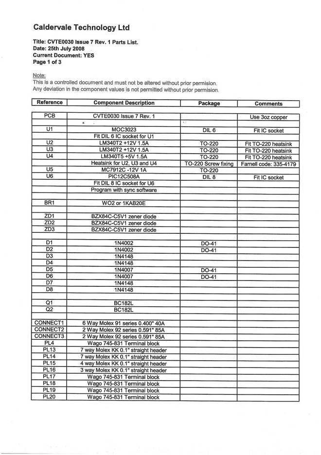
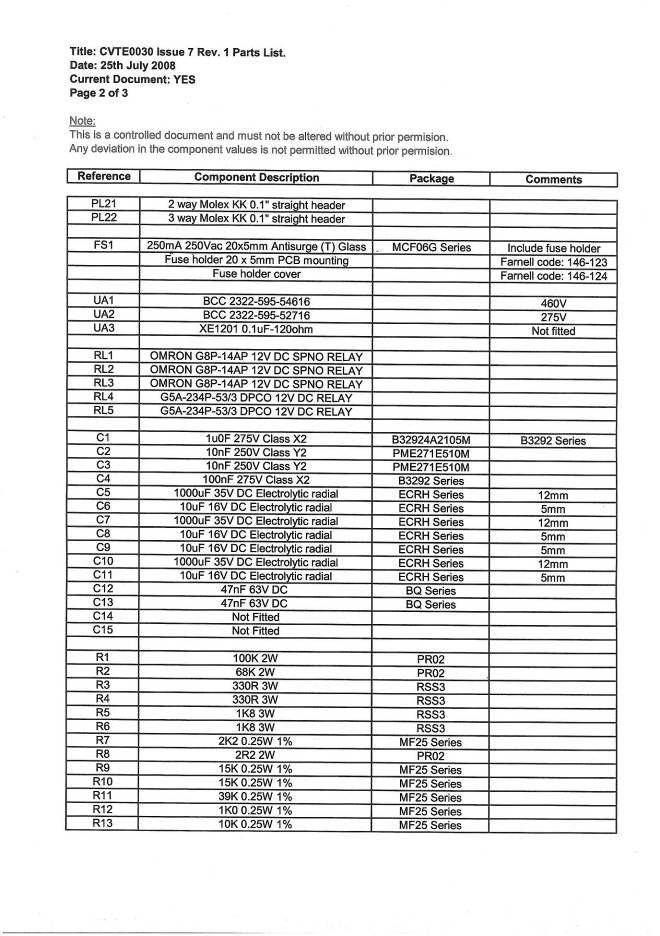
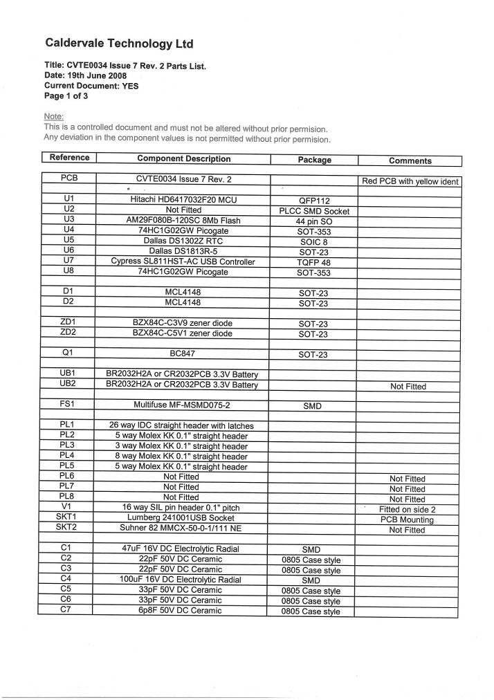
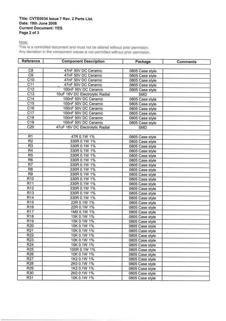
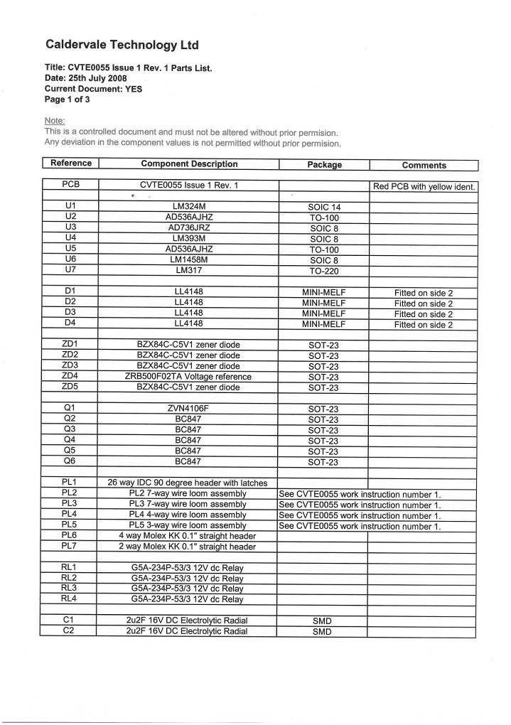
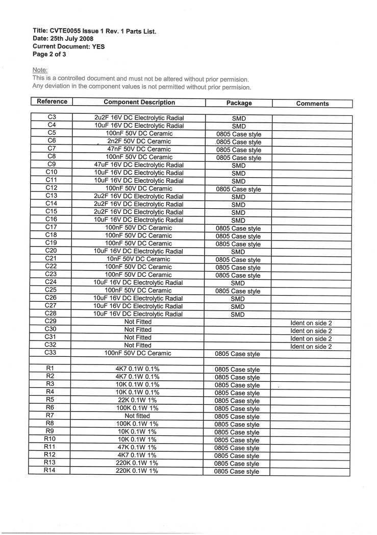
12 Section 3. Internal circuitry components. External circuitry components parts list. 11
13 Internal circuitry components kW transformer component number 10 not shown. 12
14 Internal circuitry components part list. Component Part number Description 1 CVTE0034 Issue 9 Rev 1 control board 2 CVTE0030 Issue 9 Rev 1 power board 3 CVTE0055 Issue 1 Rev 1 analogue board 4 4 line x 20 column alphanumeric display 5 Interconnecting ribbon cable assembly 6 Alphanumeric display cable loom assembly 7 Triac 8 30 amp thermal circuit breaker (110 volt supply variant) or 20 amp thermal circuit breaker (240 volt supply variant) 9 Case temperature sensor and transformer temperature sensor assembly kW transformer 13
15 External circuitry components parts list. Component Part number Description 1 Front casing (pre-drilled) 2 Back casing (pre-drilled) 3 Display label 4 Keypad label 5 Display window 6 16A Input lead assembly 7 32A Input lead assembly 8 Output lead assembly (inc. accessory bag) 9 Storage net (inc. screws) 10 Rubber casing gasket 11 Start button ( normally open contacts) 12 Stop button ( normally closed contacts) 13 Emergency stop switch complete 14 Set of M8xXXmm bolts (4 per set) for front to back casing fixing 15 Thermal circuit breaker weatherproof cover 14
16 Section 4. Circuit descriptions. 15
17 Control board circuitry (refer to drawing CVTE0034 Control Board 40V). The main components of the control board comprise of the main processor (U1), the eprom (U2), the non-volatile memory (U3), the USB controller (U7), the clock/calendar (U5) and the alphanumeric display connected to V1. The main processor controls all the functions of the machine by communicating with the eprom, non-volatile memory, clock/calendar, the display, the analogue circuitry via PL1, the control buttons via PL4, and the touch keypad via PL5. The eprom holds the software which the main processor uses to function. It is held in a holder which allows it to be removed and replaced when software updates have been issued. The non-volatile memory is used to store the weld record information and other system related information. The clock/calendar is used to store the time and date and other system related information. The USB controller controls the communication between the USB flash memory used in downloading weld information and the USB barcode reader. 16
18 Analogue board circuitry (refer to drawing CVTE0055 Analogue Board 40V). The following section gives a detailed description of the functions of the analogue board circuitry. 17
19 This page is intentionally blank 18
20 Buzzer circuit. 19
21 When Q6 is switched on via PL1/23 by the main processor on the control board CVTE0034 this allows current to flow through the buzzer connected across the connections PL7/1 and PL7/2. 20
22 +5V precision voltage reference circuit. 21
23 ZD4 is a precision voltage reference, which is used primarily to supply a stable reference voltage for the main processor s ADC processes. R31 limits the current passing through ZD4 whilst C19 and C20 provide smoothing. 22
24 Fitting resistance measurement circuit. 23
25 U7 is a 1.2V to 37V voltage regulator, which gives a 1.27V dc output. With RL3 off the resistors R45 and R46 are connected between the V OUT terminal and the V ADJ terminal; this gives a constant current of 26mA flowing out of U7 at point A. With RL3 on the resistor R45 is bypassed with R46 remaining in circuit with the V OUT and V ADJ terminals of U7; this now gives a constant current of 105mA flowing out of U7 at point A. When a fitting is connected via PL3/5 and PL3/6 and RL2 is switched on, then the selected constant current (see above paragraph) flows through the fitting resistance to 0V. This current flow through the fitting resistance develops a dc voltage at point B. This voltage passes to the circuit of R32, C21 and R33 which provides filtering before it passes through to the circuit of U6a, R34, R35, Q1 and R36 which are configured as a switchable x1 or x10 amplifier. With Q1 switched off the voltage at point B is amplified by a factor of 1; with Q1 switched on the voltage at point B is amplified by a factor of 10. The resultant voltage at point C is fed via PL1/9 to the ohms ADC input of the main processor on the control board CVTE
26 Fusamatic measurement circuit. 25
27 A Fusamatic fitting comprises of a built in fusion time determining resistor. When the fitting is connected to the output of the electrofusion unit, one side of this resistor is connected to PL3/5 via PL13/5 on the power board CVTE0030; whilst the other side is connected to PL3/7 via PL13/7 on the power board CVTE0030. By switching RL4 on, the time determining resistor is placed in series with R40 forming a potential divider circuit fed by a +5V reference voltage at point A. The resultant voltage of the potential divider circuit at point B is fed via PL1/10 to the fusamatic ADC input of the main processor on the control board CVTE0034. R39 limits the current flowing into the ADC input whilst C23 provides smoothing. Fusamatic is a registered trademark of Fusion plc. 26
28 Case and transformer T3 temperature measuring circuit. 27
29 A thermal switch is attached to the transformer T3, the switches contacts are normally open at temperatures less than +90 C; above +90 C the switches contacts close and only reset to the open position when the sensor reaches a temperature of approximately +70 C. The thermal switch is connected via PL6/1 and PL6/2 when the contacts are open the voltage at point A is held at a dc level of +5V by the resistor R30. When the contacts close point A is grounded to 0V through the switch contacts. The voltage level at point A is fed to the main processor on CVTE0034 via PL1/20. This circuit is designed to protect the transformer T3 from thermal damage. A thermistor connected across PL6/3 and PL6/4 is used to measure the temperature of the aluminium section of the casing. The thermistor along with R29 forms a potential divider, which as the resistance of the casing rises, the resistance of the thermistor, alters and therefore the voltage level at point B changes with respect to the case temperature. The voltage at point B is fed to the main processor on the control board CVTE0034 via PL1/12. The case temperature is measured to avoid the casing from becoming so hot that it becomes a hazard to the operator. At around +50 C the main processor will not permit any further welding cycles to be performed until the casing has cooled to a safe limit. 28
30 Supply voltage measuring circuit. 29
31 The secondary voltage of the PSU transformer T1 is fed into the potential divider circuit of R15 and R16 at point A. The resultant voltage of the divider circuit at point B is fed into the input of U3, which is an rms to dc convertor, which produces a direct dc equivalent output of the rms voltage feeding into the input. The dc output at point C is then fed into the circuit of R17, R18 and U1c, where it is amplified by a factor of approximately 16. The final dc voltage at point D is fed via PL1/8 to the supply voltage ADC input of the main processor on the control board CVTE0034. ZD2 clamps the voltage to 5.1 volts and C12 provides smoothing. Point A B C D Expected point value 15V ac rms 124mV ac rms 124mV dc 1.95V dc 30
32 Output current measuring circuit. 31
33 The output current flowing in the neutral output power conductor induces a current into the winding of T2 which has a reduction ratio of 100:1, therefore a current of 20A ac rms flowing in the neutral conductor will induce a reduced current of 200mA ac rms into the winding of T2. The resistor R8 develops an ac voltage across the winding of T2, which then feeds to the circuit of U1a. The table below shows the expected ac voltage values at points A and B for differing values of output current flowing in the neutral conductor. The circuit of U1a and it s associated resistors R1, R2, R3 and R4 is a differential amplifier circuit. The difference between the +ve and ve terminals on U1a is amplified by a factor of 0.5, so for an ac voltage of 440mV at point A or B the output at point C will be 220mV ac. The resultant voltage at point C is then fed into U2, which is an rms to dc convertor, which gives an equivalent dc voltage output to the ac voltage feeding in. The dc voltage at point D is fed via PL1/7 to the output current ADC pin of the main processor on the control board CVTE0034. ZD1 clamps the voltage to 5.1 volts whilst C4 provides smoothing. Neutral output power conductor 1A ac rms 5A ac rms 10A ac rms 20A ac rms 50A ac rms 60A ac rms Points A and B 22mV ac rms 110mV ac rms 220mV ac rms 440mV ac rms 1.10V ac rms 1.32V ac rms 32
34 Output voltage measuring circuit. 33
35 Relay RL1 is turned on by Q5 which in turn is activated by the main processor on the control board CVTE0034 via PL1/17; this allows the output voltage sense connections at PL13/5 and PL13/6 on the power board CVTE0030 to be connected via PL3/5 and PL3/6 respectively to the circuit of U1b. The circuit of U1b and it s associated resistors R20, R21, R22, R24 and R25 is a differential amplifier circuit. The difference between the +ve and ve terminals on U1b is amplified by a factor of 0.1, so for an ac voltage of 39.5V at point A or B the output at point C will be 3.95V ac. The resultant voltage at point C is then fed into U5, which is an rms to dc convertor, which gives an equivalent dc voltage output to the ac voltage feeding in. The dc voltage at point D is fed via PL1/5 to the output voltage ADC pin of the main processor on the control board CVTE0034. ZD3 clamps the voltage to 5.1 volts whilst C16 provides smoothing. 34
36 Output control circuit. 35
37 The control output is fed to point A from the main processor on the control board CVTE0034 via PL1/4. The low pass filter of R8 and C5 with a cut-off frequency of approximately 1.6Hz, filters out the PWM (pulse width modulation) output of the main processor to give a dc level control reference at point B. The circuit of U1d, R9 and R10 amplify the voltage at point B by a factor of 2 whilst C6 provides high frequency cut-off. The amplified dc voltage at point D is then fed via R14 to the positive terminal of U4b. The supply synchronisation pulses at point C are fed from the power board via PL5/2 into the positive terminal of U4a, which is a comparator. As the pulses rise above and fall below the level on the negative terminal this allows C7 to charge and discharge giving a ramp waveform at point E. When the ramp waveform level on the negative terminal of U4b rises above and falls below the control reference on the positive terminal of U4b which again is a comparator, U4b gives a pulsed output which in turn switches the opto-isolator triac on the power board CVTE0030 on and off in synchronisation with the supply frequency. The diagram overleaf shows the synchronisation of the output power waveform with respect to the ac supply waveform as well as the magnitude of the output waveform in relation to the control reference passing through the ramp waveform. 36
38 37 Caldervale Technology Limited +V -V 0V +5V AC SUPPLY WAVEFORM 10ms T 1 S E C O N D A R Y H A LF W A V E R E C T IF IE D SYNCHRONISATION PULSES 0V +10V R A M P W A V E F O R M 0V +10V OUTPUT CONTROL LEVEL control reference 0V +12V T R IA C F IR E P U L S E S 0V +V O U T P U T P O W E R W A V E F O R M -V triac fired here
39
40 Power board circuitry (refer to drawing CVTE0030 Power Board). The EMC filter consists of the components L1, C1, C2, C3 and R1. The choke L1 is designed to stop common mode noise entering or leaving the machine via the input lead and forms part of the filter along with the X capacitor C1 and the two Y capacitors C2 and C3. R1 provides a discharge path for the capacitors. UA1 (and UA2 240V only) is fitted to remove any excess voltage spikes. The power supply is a conventional linear supply. The secondary of the transformer T1 is fed into a bridge rectifier BR1, the voltage regulators U3, U4 and U5 are fed from the bridge rectifier and produce the dc voltage levels required by the rest of the circuitry. U2 is a +12 volt dc rectifier fed directly from the secondary of T1 via the diodes D1 and D2 which provide full wave rectification, this voltage is used to supply all the dc relays. All the capacitors within the power supply circuitry are used for smoothing of the rectified voltages. U1 is an opto-isolator which with it s associated circuitry is used to switch the triac on (the triac automatically switches off at the zero voltage crossing point). U1 in turn is switched on and off by the pulses entering it at pin 2 from the analogue circuit board (see Analogue board circuitry, Output control circuit). R3, R4 (240V only), R5, R6 (240V only) and C4 provide dv/dt transient suppression to avoid the false switching of the triac. To control the welding voltage accurately, the zero voltage crossing points of the supply waveform have to be detected in order to switch the triac on with the correct timing. The secondary of T1 is used to provide a reference of the supply voltage waveform, this secondary voltage is full wave rectified by D3 and D4 with some filtering provided by the resistors R9 and R10 and the capacitors C12 and C13. This rectified voltage is clipped with a 5.1 volt zener diode ZD1 before being fed into pin 5 of U6. U6 is a small microcontroller which is used to time the period between the waveform pulses and digitally filters out any spurious ones. The filtered signal is then fed to the analogue board (see Analogue board circuitry, Output control circuit) and also to the main processor for supply frequency measurement. When the relay RL1 is activated the supply voltage is allowed to flow through the primary of the 2.5kW transformer T3. RL1 in turn is activated by RL4 which is switched on and off by the main processor. When relays RL2 and RL3 are activated the secondary voltage of T3 is allowed to flow through to output. RL2 and RL3 are in turn is activated by RL5 which again is switched on and off by the main processor. The purpose of this double switching of the 2.5kW transformer is to reduce the possibility of the triac being inadvertently switched on due to transients which may appear as the supply voltage is connected to the triac, in this case the voltage passed by the triac will only flow in the primary of T3 for that half waveform cycle as the secondary circuit will still be open with RL2 and RL3 not being activated. T2 is a current transformer with a ratio of 100:1 which allows for the measurement of the output current. R8 is used to develop a voltage from the current induced into the windings of T2, this voltage is then fed to the analogue board (see Analogue board circuitry, Output current measuring circuit). 39
41 Section 5. Circuit diagrams. Circuit board interconnections Circuit board component parts lists 40
42 41 Caldervale Technology Limited
43 42 Caldervale Technology Limited
44 43 Caldervale Technology Limited

45 44 Caldervale Technology Limited
46 Calder Centaur circuit board interconnections. Caldervale Technology Limited CVTE0030 CVTE0055 CVTE0034 CVTE0039 Description PL14/1 PL2/1 PL1/13 SECONDARY RELAY ENABLE PL14/2 PL2/2 PL1/25 SECONDARY RELAY SENSE PL14/3 PL2/3 PL1/20 NOT USED PL14/4 PL2/4 PL1/24 PRIMARY RELAY ENABLE PL14/5 PL2/5 PL1/3 PRIMARY RELAY SENSE PL14/6 PL2/6 PL1/18 NOT USED PL14/7 PL2/7 PL1/22 NOT USED PL13/1 PL3/1 OUTPUT CURRENT SENSE 1 PL13/2 PL3/2 OUTPUT CURRENT SENSE 2 PL13/3 PL3/3 NOT USED PL13/4 PL3/4 +12VR (RELAY DC SUPPLY) PL13/5 PL3/5 FITTING SENSE 1 PL13/6 PL3/6 FITTING SENSE 2 PL13/7 PL3/7 FUSAMATIC SENSE PL15/1 PL4/1 PL1/11 0V PL15/2 PL4/2 PL1/1 +12V PL15/3 PL4/3-12V PL15/4 PL4/4 PL1/2 +5V PL16/1 PL5/1 TRIAC SWITCHING PULSES PL16/2 PL5/2 PL1/21 SUPPLY FREQUENCY PL16/3 PL5/3 SUPPLY VOLTAGE SENSE PL1/6 PL1/6 +5V REFERENCE PL1/4 PL1/4 OUTPUT LEVEL CONTROL PL1/5 PL1/5 OUTPUT VOLTAGE ADC PL1/8 PL1/8 SUPPLY VOLTAGE ADC PL1/7 PL1/7 OUTPUT CURRENT ADC PL1/10 PL1/10 FUSAMATIC ADC PL1/9 PL1/9 OHMS ADC PL1/12 PL1/12 CASE TEMPERATURE ADC PL1/16 PL1/16 OHMS RELAY ENABLE PL1/15 PL1/15 OHMS x4 ENABLE PL1/14 PL1/14 OHMS x10 ENABLE PL1/17 PL1/17 OUTPUT SENSE RELAY ENABLE PL1/23 PL1/23 BUZZER ENABLE PL1/26 PL1/26 FUSAMATIC RELAY ENABLE PL1/19 PL1/19 NOT USED PL5/1 PL1/2 KEYPAD +5V PL5/2 PL1/4 KEYPAD RESET PL5/3 PL1/3 KEYPAD CS PL5/4 PL1/5 SERIAL DATA PL5/5 PL1/1 KEYPAD 0V 45
47 46
48 47
49 48
50 49
51 50
52 51
53 52
54 53
55 54
56 This page is intentionally blank. Caldervale Technology Limited 55
57
58 Section 6. Disassembly and refitting of assemblies. Caldervale Technology Limited 57
59
60 6.1 Removing the control board. Caldervale Technology Limited Remove the leads connected to the plugs marked A, B, C, D and E. Remove the four M4 lock nuts marked H, lift the board upwards and finally remove the lead marked F from the underside of the board as shown below in figure 1. Figure 1. H D A B C H H E H F Remove the rubber grommets from the control board. 59


61 6.2 Fixing the control board. Figure 1. A Caldervale Technology Limited BLACK WIRE Connect the LCD wire loom to the control board in the orientation as shown above in figure 1, ensuring that the outer black wire is connected to the pin marked A. Figure 2. H D A B C H H E H F Fit the rubber grommets to the control board and place the board in place making sure that it is aligned over the mounting pillars, secure in place using the M4 lock nuts in the positions marked H in figure 2 above. Referring to figure 2 above reconnect the ambient temperature assembly socket to the plug marked A, the USB assembly socket to the plug marked B, the interconnecting wire loom assembly socket to the plug marked C, the keypad wire loom assembly socket to the plug marked D, and the start/stop switch wire loom assembly socket to the plug marked E. 60
62 6.3 Removing the LCD module. Remove the control board as shown in section 6.1. Disconnect the wire loom as shown below in figure 1. Figure 1. Caldervale Technology Limited Remove the four M3 Nyloc nuts, washers and panel grommets at the positions marked A in figure 2 below. Lift the display module clear of the front casing. Figure 2. A A A A 61


63 6.4 Fitting the LCD module. Caldervale Technology Limited Locate the display module over the four M3 pillars and secure in place using four M3 lock nuts in the positions marked A in figure 1 below. Figure 1. A A A A Reconnect the wire loom as shown below in figure 2. Refit the control board as shown in section 6.1. Figure 2. 62

64 6.5 Removal and refitting of the start or stop button. Removal. Remove the control board as in section 6.1. Using a pair of pliers release the actuator locking nut, and remove the actuator from the front casing as shown below in figure 1. Figure 1. Refitting. Refitting of the start or stop buttons is the reverse of the removal process. 63


65 6.6 Removal and refitting of the ambient temperature sensor. Removal. Loosen the gland nut of the temperature sensor housing as shown in figure 1 below. Figure 1. Figure 2. From the inside of the back casing pull out the ambient temperature assembly, as shown above in figure 2. Refitting. From the inside of the back casing insert the ambient temperature assembly, and tighten the gland nut to secure the sensor body in the housing so that the end of the sensor body is level with the end of the housing as shown below in figure 3. Figure 3 64
66 6.7 Removal of the analogue board. Caldervale Technology Limited Remove the plugs marked A and B (if external sounder fitted remove plug from position C) as shown below in figure 1. Remove the M3 nylock nuts and fibre washers at the positions marked D, shown in figure 1 below and lift the analogue board clear of the mounting pillars. Figure 1. D D D D A D B C D Carefully remove the plugs marked E and F from the power board as shown below in figure 2. Tilt the analogue board slightly upwards and remove from the power board the two plugs marked G and H as shown below in figure 3. The analogue board can now be fully removed. Figure 2. Figure 3. H E F G 65
67 6.8 Fitting of the analogue board. Caldervale Technology Limited Ensure that each of the six mounting pillars each have an M3 fibre washer placed over the threaded stud. Locate the analogue board over the mounting pillars and connect the two plugs marked G and H to the power board as shown below in figure 1. Connect the two plugs marked G and H to the power board as shown below in figure 2. Figure 1. Figure 2. H G E F The analogue board can now be secured to the mounting pillars using the M3 fibre washers and the M3 nylock nuts in the six positions marked D as shown below in figure 3. Figure 3. D D D D A B D C D Referring to figure 3 above, connect the interconnecting ribbon cable assembly socket to the position marked A, and connect the case and toroid assembly socket to the position marked B. If an external sounder is fitted connect the socket to the plug marked C. 66

68 6.9 Removal of the input lead assembly. Caldervale Technology Limited Remove the lower casing by removing the four M5 screws as shown below in figure 1. Disconnect the input lead connections from inside the unit. Figure 1. Release the retaining nut on the input lead gland shown in figure 2 and remove the input lead assembly. Figure Fitting of the input lead assembly. Fitting of the input lead assembly is the reverse of the removal process. 67

69 6.11 Removal of the output lead assembly. Caldervale Technology Limited Remove the back casing by removing the four M5 screws as shown below in figure 1. Disconnect the output lead assembly connections from inside the unit. Figure 1. Release the retaining nut on the output lead gland shown in figure 2 and remove the output lead assembly. Figure Fitting of the output lead assembly. Fitting of the output lead assembly is the reverse of the removal process. 68
70 Section 7. Fault finding. Caldervale Technology Limited 69
71
72 Symptom Fault. Suggestion. No display when connected to the supply. Thermal circuit breaker tripped-out. Check the thermal breaker - reset if required. (with no backlight illuminated) Disconnection of the L or N conductor Check the wiring connections inside the plug. inside the plug. Break in the input lead conductors. Measure the supply voltage inside the machine - replace the input lead if necessary. PSU fuse blown. Check/replace fuse. Fault with the PSU dc supplies. Check the PSU dc supply voltages. Fault with the interconnecting wiring loom. Check/replace interconnecting wiring loom. Fault with the display module wiring loom. Check/replace display module wiring loom. Fault with the LCD module. Check/replace LCD module. Fault with the control board. Check/replace control board. No display when connected to the supply. Fault with the display module wiring loom. Check/replace display module wiring loom. (with backlight illuminated) Fault with the LCD module. Check/replace LCD module. Fault with the control board. Check/replace control board. Keypad not responding. Fault with keypad connector to control board. Check keypad connector. Fault with keypad. Change keypad. No recognition of the USB flash disk. Faulty USB flash disk. Try another USB flash disk. Faulty USB wiring assembly. Check/replace USB wiring assembly. Faulty USB host controller chip. Replace the control board. No recognition of the USB barcode reader. Faulty USB barcode reader. Faulty USB wiring assembly. Faulty USB host controller chip. Try another USB barcode reader. Check/replace USB wiring assembly. Replace the control board. 71
73 Symptom Fault. Suggestion. After 4 seconds weld stops. Triac fault. Check/replace triac. Display shows: E07 Fault with triac switching circuit. Check/replace analogue board. Excessive output voltage Fault with output voltage measurement circuit. Check/replace analogue board. No control from processor. Check/replace interconnecting ribbon cable. Check/replace control board. After 6 seconds weld stops. Fault with triac switching circuit. Check/replace analogue board. Display shows: E06 Fault with output voltage measurement circuit. Check/replace analogue board. Output voltage high Machine requires calibration. Recalibrate and check. Processor fault. Check/replace control board. After 6 seconds weld stops. Low supply voltage Check supply. Display shows: E05 Generator under powered Check generator rating. Output voltage low Fault with output voltage measurement circuit. Check/replace analogue board. Fault with triac switching circuit. Machine requires calibration. Processor fault. Check/replace analogue board. Recalibrate and check. Check/replace control board. After 6 seconds weld stops. Accessory (fitting / coupler) fault. Change accessory (fitting / coupler). Display shows: E17 (heating coils have shorted together) Current Surge 72
74 Symptom Fault. Suggestion. After 6 seconds weld stops. Accessory (fitting / coupler) fault. Change accessory (fitting / coupler). Display shows: E09 Output lead fault. Check/replace output lead terminal ends. Output current low Fault with output current measurement circuit. Check/replace analogue board. Machine requires calibration. Recalibrate and check. Processor fault. Check/replace control board. Display shows: E01 High supply voltage Check supply. Supply voltage high Fault with supply voltage measurement circuit. Check/replace analogue board. Machine requires calibration. Recalibrate and check. Processor fault. Check/replace control board. Display shows: E02 Low supply voltage Check supply. Supply voltage low Fault with supply voltage measurement circuit. Check/replace analogue board. Machine requires calibration. Recalibrate and check. Processor fault. Check/replace control board. Display shows: E03 High supply voltage frequency Check supply. Supply frequency high Fault with supply frequency measurement circuit. Check/replace analogue board. Machine requires calibration. Recalibrate and check. Processor fault. Check/replace control board. Display shows: E04 Low supply voltage frequency Check supply. Supply frequency low Fault with supply frequency measurement circuit. Check/replace analogue board. Machine requires calibration. Recalibrate and check. Processor fault. Check/replace control board. Display shows: E09 Output lead disconnected. Check output lead connection. Fitting connection fault Output lead fault. Check/replace output lead. Check/replace output socket wiring loom. 73
75 Symptom Fault. Suggestion. Display shows: Output fault Output voltage detected on the output at power up. Check wiring connections to the earth (ground) terminal on the casing. Check transformer earth (ground) lead terminal connectors. Display shows: The primary relay has failed to activate. Check connections to power board. Primary relay fault Check/replace control board. Check/replace power board. Display shows: The secondary relays have failed to activate. Check connections to power board. Secondary relay fault Check/replace control board. Check/replace power board. Display shows: The primary and secondary relays have failed to Check connections to power board. Primary & secondary relay fault activate. Check/replace control board. Check/replace power board. Display shows: The USB module has not responded. Check the USB module is inserted correctly. Vinculum not present Check/replace USB module. Check/replace control board. 74
76 Section 8. Modifications. Caldervale Technology Limited 75
SE-135 MANUAL GROUND-FAULT GROUND-CHECK MONITOR
 SE-135 MANUAL GROUND-FAULT GROUND-CHECK MONITOR AUGUST 14, 2001 REVISION 1 Publication: SE-135-M Document: S95-C135-00000 Printed in Canada. Copyright 2001 by Startco Engineering Ltd. All rights reserved.
2.) Cabinet setup and preset data shall, as standard, be fully user programmable on a per cabinet or system wide basis.
 Cabinet setup and preset data shall, as standard, be fully user programmable on a per cabinet or system wide basis.") A21 DIMMER CABINET SPECIFICATION. GENERAL. A.) Overview. 1.) The dimmer cabinets shall be fully digital, designed specifically for architectural and entertainment lighting applications, and shall consist
A21 DIMMER CABINET SPECIFICATION. GENERAL. A.) Overview. 1.) The dimmer cabinets shall be fully digital, designed specifically for architectural and entertainment lighting applications, and shall consist
Autoranging True RMS Multimeter User Manual
 Autoranging True RMS Multimeter User Manual Please read this manual before switching the unit on. Important safety information inside. Contents Page 1. Safety Information... 4 2. Safety Symbols... 5 3.
********SERVICE MANUAL******** MODELS:
 ********SERVICE MANUAL******** MODELS: 75211-10 Variable Speed Drive, 5000 RPM, 115 V 75211-15 Variable Speed Drive, 5000 RPM, 230 V, CE Mark 75211-60 Variable Speed Drive w/pump, 9000 RPM, 115 V 75211-62
2 in 1 LAN Tester and Multimeter Model:
 2 in 1 LAN Tester and Multimeter Model: 72-8495 1 IMPORTANT SAFETY INFORMATION Please read these instructions carefully before use and retain for future reference. This instrument is designed and manufactured
CHAPTER 3B: ELECTRONIC POWER STEERING
 Electronic Power Steering CHAPTER 3B: ELECTRONIC POWER STEERING NOTE: The basic steering system, such as the tie rod ends, drag links axles, etc., is covered in Chapter 3A: Steering. In 2012, Cub Cadet
OPERATING INSTRUCTION
 OPERATING INSTRUCTION AUTORANGING MULTIMETER MAX Ω F C 10A MAX every 15 min. COM V SAFETY INFORMATION The following safety information must be observed to insure maximum personal safety during the operation
S-14 S-14. Compact Digital Multimeter. Compact Digital Multimeter
 S-14 Compact Digital Multimeter S-14 Compact Digital Multimeter SAFETY INFORMATION The following safety information must be observed to insure maximum personal safety during the operation at this meter
BA505C 2-wire 4/20mA manual setpoint station Issue 6
 BA505C 2-wire 4/20mA manual setpoint station Issue 6 Issue: 6 3 rd December 2010 2 CONTENTS 1. Description 2. Operation 3. Electrical Systems Design 3.1 4/20mA loop 3.2 Optional Backlights 3.2.1 Separately
DEEP SEA ELECTRONICS PLC DSE103 MK II Speed Switch Operators Manual
 DEEP SEA ELECTRONICS PLC DSE103 MK II Speed Switch Operators Manual Document number 057-135 Author : Paul Gibbons DSE103 MKII Operator Manual Issue 1 Deep Sea Electronics Plc Highfield House Hunmanby North
GV3000/SE AC Drive ControlNet Network Communication Option Board M/N 2CN3000
 GV3000/SE AC Drive ControlNet Network Communication Option Board M/N 2CN3000 Instruction Manual D2-3390-2 The information in this manual is subject to change without notice. Throughout this manual, the
Intrinsically safe batch controller Batching Master 110i
 Intrinsically safe batch controller Batching Master 110i Installation Guide BVS 04 AT E 172 Revision 12.2 IBS BatchControl GmbH Im Sträßchen 2-4 Tel.: ++49 2441 9199 801 53925 Kall Fax.: ++49 2441 9199
Expansion Unit Catalog Nos , - 152, - 153, - 154, - 156, -E157
 PRODUCT DA TA SLC 150 110 Expansion Unit Catalog Nos. 1745-151, - 152, - 153, - 154, - 156, -E157 7 : The EXpdnSiQn Unit The SLC 150 expansion unit can be used with either the SLC 150 processor unit or
Strain gauge Measuring Amplifier GSV-1A8. Instruction manual GSV-1A8, GSV-1A8USB, GSV-1A16USB
 Strain gauge Measuring Amplifier GSV-1A8 Instruction manual GSV-1A8, GSV-1A8USB, GSV-1A16USB GSV-1A8USB SubD1 (front side) GSV-1A8USB M12 (front side) GSV-1A16USB (rear side) GSV-1A8USB K6D (front side)
Installation Manual for D244X Series 24-volt Power Supplies
 Installation Manual for D244X Series 24-volt Power Supplies D2441-B D2441-C D2443-B D2443-C D2445-B D2445-C D2400 Series 1A 24 volts 1A 24 volts 3A 24 volts 3A 24 volts 5A 24 volts 5A 24 volts Dycon Power
D115 The Fast Optimal Servo Amplifier For Brush, Brushless, Voice Coil Servo Motors
 D115 The Fast Optimal Servo Amplifier For Brush, Brushless, Voice Coil Servo Motors Ron Boe 5/15/2014 This user guide details the servo drives capabilities and physical interfaces. Users will be able to
DEEP SEA ELECTRONICS PLC
 COMPLEX SOLUTIONS MADE SIMPLE DEEP SEA ELECTRONICS PLC DSE705 ATS CONTROL MODULE OPERATING MANUAL Deep Sea Electronics Plc Highfield House Hunmanby North Yorkshire YO14 0PH ENGLAND Sales Tel: +44 (0) 1723
POCKET MULTIMETER Model No: MM18
 INSTRUCTIONS FOR: POCKET MULTIMETER Model No: MM18 Thank you for purchasing a Sealey product. Manufactured to a high standard this product will, if used according to these instructions and properly maintained,
Chassis Power Supplies
 PDC24 / PAC Chassis Power Supplies (PDC24 / PAC) Issue 3 October 2005 INTRODUCTION PURPOSE Two Power Supply Units (PSUs) provide a dual-redundant source of 5.4Vand 12Vdc onto the backplane for the modules
RT4F-120V/20A-WAC RECTIFIER
 The RT4F-120V/20A-WAC is a switched mode rectifier/charger module designed to provide up to 20A of output current into a 120V nominal system. This charger has been designed for use in conjunction with
DM-918 OPERATIONS MANUAL AUTORANGING MULTIMETER
 DM-918 OPERATIONS MANUAL AUTORANGING MULTIMETER SAFETY INFORMATION The following safety information must be observed to ensure maximum personal safety during the operation of this meter: This meter is
Operating Instructions
 CHEMICAL DRAINAGE SYSTEMS Fusion Lock Welding Unit Operating Instructions Table of Contents Specifications...................................................... 4 Important!.........................................................
MANUAL FOR THE UNIVERSAL MANUAL CONTROLLER UMC - 31
 MANUAL FOR THE UNIVERSAL MANUAL CONTROLLER UMC - 31 PPS PART NO. 133550 DRAWING NO. 133550-10 THIS MANUAL ASSIGNED TO THE S/N: THE INFORMATION CONTAINED IN THIS MANUAL IS PROPRIETARY TO PACIFIC POWER SOURCE,
User's Guide. MiniTec TM Series Model MN25 MultiMeter
 User's Guide MiniTec TM Series Model MN25 MultiMeter Warranty EXTECH INSTRUMENTS CORPORATION warrants this instrument to be free of defects in parts and workmanship for one year from date of shipment (a
Assembling and testing electronic circuits. Outcome one
 006 UNIT 036 Assembling and testing electronic circuits Learning outcomes 1 2 Know how to assemble and test electronic circuits Performance evidence must be the main form of evidence gathered. Candidates
DESIGO RX Individual room controllers. for fan-coil systems, chilled ceilings and radiators, with LONMARK-compatible bus communications
 3 834 DESIO RX Individual room controllers for fan-coil systems, chilled ceilings and radiators, with MARK-compatible bus communications RXC20.1 RXC21.1 The RXC20.1 and RXC21.1 controllers are used for
HAND-HELD THERMOCOUPLE THERMOMETER SERVICE MANUAL. CATALOG NUMBERS , and , and PROPRIETARY
 HAND-HELD THERMOCOUPLE THERMOMETER SERVICE MANUAL CATALOG NUMBERS 600-1000, 600-1010 and 600-1020 91100-00, 91100-10 and 91100-20 PROPRIETARY Information contained in this manual is proprietary to COLE-PARMER
OPERATING INSTRUCTIONS 7 SERIES STATIC GENERATORS
 OPERATING INSTRUCTIONS 7 SERIES STATIC GENERATORS GB Contents Page 1 Introduction 4 2 Safety 5 3 Use 6 4 Checking on Delivered Equipment 6 5 General Specification and Dimensions 7 6 Positioning 10 7 Operating
GV3000/SE Operator Interface Module (OIM) User Guide Version 2.0 M/N 2RK3000
 User Guide Version 2.0 M/N 2RK3000") GV3000/SE Operator Interface Module (OIM) User Guide Version 2.0 M/N 2RK3000 Instruction Manual D2-3342-2 The information in this manual is subject to change without notice. Throughout this manual, the
GV3000/SE Operator Interface Module (OIM) User Guide Version 2.0 M/N 2RK3000 Instruction Manual D2-3342-2 The information in this manual is subject to change without notice. Throughout this manual, the
Model HM-535 Power Supply Installation and Service Instructions
 Model HM-535 Power Supply Installation and Service Instructions 430-535 0104 2004 Heritage MedCall, Inc SENTRY INSTALLATION & SERVICE INSTRUCTIONS POWER SUPPLY UNIT Model HM-535 IMPORTANT SAFETY INSTRUCTIONS
The PCI Series. Precise power control for complex SCR applications. Phase Angle Fired SCR Power Controls AMPS VAC
 The PCI Series Phase Angle Fired SCR Power Controls 25-1200 AMPS 120-600 VAC Precise power control for complex SCR applications. ROBICON 1996 Distributed Worldwide by www.mcgoff-bethune.com Applications
Accessories for stand-alone gird inverter SMART LOAD 6000
 Accessories for stand-alone gird inverter SMART LOAD 6000 Technical Description SL6000-TEN081820 98-2001320 Version 2.0 EN Table of Contents Table of Contents 1 Notes on this Manual..............................
Non-communicating room controllers
 3 882 DESIGO RXA Non-communicating room controllers RXA29.1 For fan-coil systems The RXA29.1 room controller are used for temperature control in individual rooms. For 2-pipe or 4-pipe fan-coil systems,
MODEL SW6000 & SM6100 CENELEC INSTRUCTIONS
 MODEL SW6000 & SM6100 CENELEC INSTRUCTIONS Installation Manual 1180 METRIX Experience Value 8824 Fallbrook Dr. Houston, TX 77064, USA Tel: 1-281-940-1802 After Hours Technical Assistance: 1-713-702-8805
TD-700 FLUOROMETER SERVICE MANUAL
 TD-700 FLUOROMETER SERVICE MANUAL July 1996 CONTENTS Page Section 1 INTRODUCTION 2 Section 2 PRELIMINARY CHECKS 3 Section 3 TROUBLESHOOTING GUIDE 5 A. Lamp (Fluorescent) 5 B. Lamp Heater 7 C. Fan 8 D.
Installation Instructions
 Installation Instructions This document provides information on: important pre-installation considerations power supply requirements installing the module connecting the wiring using the indicators for
P522 Signal Processor
 P522 Signal Processor INSTALLATI INSTRUCTIS Self-Check Contact Ratings: Max switching power - 60 W 125Vac Max switching voltage - 220VDC, 250Vac Max switching current - 2A DC, AC Analog Flame Signal: User
TOA ELECTRIC CO., LTD.
 Operating Instruction Manual TOA MIXING CONSOLE Model RX-31C TOA ELECTRIC CO., LTD. KOBE, JAPAN Contents General Description...2 Features...2 Front Panel...3 Rear Panel...4 Rack Mounting Instructions...5
Mini Digital Multimeter
 User Manual Mini Digital Multimeter Model MN15A Additional User Manual Translations available at www.extech.com Introduction Congratulations on your purchase of the Extech MN15A MultiMeter. The MN15A offers
Model INSTRUCTION MANUAL DIGITAL MULTIMETER
 Model 57040 INSTRUCTION MANUAL DIGITAL MULTIMETER SAFETY INFORMATION This multimeter has been designed according to IEC 1010 concerning electronic measuring instruments with an overvoltage category (CAT
DRTS 3 PLUS Advanced Protection Relay Test Set and Measurement System
 Advanced Protection Relay Test Set and Measurement System Multi-tasking equipment designed for testing protection relays, energy meters, transducers Particularly designed to test RTU (remote terminal unit)
MICRO BURN IN PRODUCTS LISTED IN MODEL NUMBER ORDER FOLLOWED BY A BRIEF DESCRIPTION
 MICRO BURN IN PRODUCTS LISTED IN MODEL NUMBER ORDER FOLLOWED BY A BRIEF DESCRIPTION MODEL 102P 102R DESCRIPTION Floor Stand (Plane) Floor Stand (Modified) HTRB Burn-In System (diode) Component Burn-In
MAXIMA+ Series Rotary Level Indicator
 MAXIMA+ Series Rotary Level Indicator BinMaster: Division of Garner Industries 7201 N. 98th St., Lincoln, NE 68507 402-434-9102 email: info@binmaster.com www.binmaster.com OPERATING INSTRUCTIONS PLEASE
GSV-1A4 M12/2 M12/2. Highlights
 GSV-1A4 M12/2 M12/2 Highlights Input sensitivity: 2mV/V; 4mV/V, 2 mv/v, 1mV/V, 0.5mV/V configurable via jumpers Output signals ±10V AND 12mA+-8mA on 15 pin Sub-D Integrated half and quarter bridge completion
MiG2 CONTROLLERS. 2 & 4 Stage General Purpose Controllers, with Air-conditioning Facilities
 MiG2 CONTROLLERS 2 & 4 Stage General Purpose Controllers, with Air-conditioning Facilities The MiG2 controllers incorporate: 2 Inputs (Configurable as Resistive, 0 10V, 0 20mA or 4 20mA) 2 or 4 Relay Outputs
INTRINSICALLY SAFE Ex ia PSU TYPE AC36W
 Title INTRINSICALLY SAFE Ex ia PSU TYPE AC36W USER MANUAL Document Number 66-184-12 Issue 10 10 Update new logo and address 2017.10.18 CW CW PC 09 Added Um as 265V, Io up to 3.3A & IIB data 2017.08.21
Copyright 2014, R. Eckweiler & OCARC, Inc. Page 1 of 6
 HOM rev. new Heathkit of the Month: by Bob Eckweiler, AF6C Heathkit of the Month #52 - SK-211 AC Monitor Heathkit SK-211 AC Monitor Introduction: When club president, Nicholas - AF6CF, mentioned he had
OPERATING MANUAL FOR THE 30KV A.C. TEST SET P123. Bicotest High Voltage Products Ltd
 OPERATING MANUAL FOR THE 30KV A.C. TEST SET P123 Product: High Voltage AC Test Set Type: P123 Bicotest High Voltage Products Ltd Hellesdon Park Road, Drayton High Road, Norwich NR6 5DR United Kingdom Phone
Data Sheet T 6493 EN. TROVIS 6400 Automation System TROVIS 6493 Compact Controller. For panel mounting (front frame 48 x 96 mm/1.89 x 3.
 Data Sheet T 6493 EN TROVIS 6400 Automation System TROVIS 6493 Compact Controller For panel mounting (front frame 48 x 96 mm/1.89 x 3.78 inch) Application Digital controller to automate industrial and
AIR COOLED MODULAR RECTIFIER
 CONTROLLED POWER COMPANY SPECIFICATIONS AIR COOLED MODULAR RECTIFIER Spc1800a1 5JAN1999 SPECIFICATION S-1800-A MODULAR (REMOVABLE AND NON-REMOVABLE MODULES) AIR COOLED RECTIFIER Standard output power range:
Answers to Chapter 2 Review Questions. 2. To convert controller signals into external signals that are used to control the machine or process
 Answers to Chapter 2 Review Questions 1. To accept signals from the machine or process devices and to convert them into signals that can be used by the controller 2. To convert controller signals into
4100 and 4100/R Controllers
 The TR TASC Unit speed controller is available in two formats: 4100 for panel mounting 4100/R for rack mounting Facilities are identical for the two models. Construction The p.c.b. card is 0.0625 in flame
POWER SAVER METER USING MICROCONTROLLER TO SAVE ELECTRICITY UPTO 30-40%
 POWER SAVER METER USING MICROCONTROLLER TO SAVE ELECTRICITY UPTO 30-40% Prof. Dipesh. M.Patel 1 Kandarp mehta 2 Himanshu amrutiya 3 Ravi bhalodia 4 Chirag amrutiya 5 1. Head, Electrical Engg. Department,
Expansion Module HZS 541-1S
 Expansion Module HZS 541-1S 12.10.2015 Page 1 System Description The external HZS 541-1S expansion module provides users of biomass heating systems with additional 230 V AC relay outputs, analog inputs
Non-communicating room controllers
 3 881 DESIO RXA on-communicating room controllers For fan-coil systems RXA20.1 RXA21.1 RXA22.1 The RXA20.1, RXA21.1 and RXA22.1 room controllers are used for temperature control in individual rooms. For
AIM & THURLBY THANDAR INSTRUMENTS
 AIM & THURLBY THANDAR INSTRUMENTS MX100T & MX100TP Triple output dc power supplies - 315 watts Three full performance outputs of equal power Multiple-ranges, up to 70V and up to 6A Ultra-compact size for
RT4B-110V/12A RECTIFIER
 The RT4B-110V/12A is a switched mode rectifier (SMR) module designed to provide up to 12A of output current into a 110V nominal system. It can be used with or without a cooling fan. With a fan it runs
Q22 DATRAN II excel Owners Manual
 Q22 DATRAN II excel Owners Manual Manual Revision No. 1.03 Dated November 2001 Copyright 2000 to QTech Data Systems Limited Christchurch, NEW ZEALAND All rights reserved The circuit details and know how
WBS HARDWIRED SERIES 4-60KVA MAINTENANCE BYPASS SWITCH
 WBS HARDWIRED SERIES 4-60KVA MAINTENANCE BYPASS SWITCH Man 440 Issue 7 1 1. INTRODUCTION... 3 2. INSTALLATION... 3 2.1 Connection of the Mains Supply... 3 2.2 Connection of the Input to the UPS... 4 2.3
PMC Controller Electrical Manual
 PMC Controller Electrical Manual 1 of 16 07/09/16 Table of Contents Electrical Installation...3 Overview...3 IO Overview...3 Inputs... 3 Encoders (A /A B /B Z /Z)...3 Analogue Input (ADC0-3)...4 Digital
RT4F-110V/25A RECTIFIER
 The RT4F-110V/25A is a hot-pluggable switched mode rectifier (SMR) module designed to provide up to 25A of output current into a 110V nominal system. Examples of such systems are 60 cells lead acid (136V
WARNING CAUTION 1. SAFETY
 Instructions for: Professional auto ranging Digital Multimeter - 8 Function MOdel No: TM102 Thank you for purchasing a Sealey product. Manufactured to a high standard, this product will, if used according
MAINTENANCE MANUAL. EDACS REDUNDANT POWER SUPPLY SYSTEM 350A1441P1 and P2 POWER MODULE CHASSIS 350A1441P3, P4, AND P5 POWER MODULES TABLE OF CONTENTS
 MAINTENANCE MANUAL EDACS REDUNDANT POWER SUPPLY SYSTEM 350A1441P1 and P2 POWER MODULE CHASSIS 350A1441P3, P4, AND P5 POWER MODULES TABLE OF CONTENTS SPECIFICATIONS*... 2 INTRODUCTION... 3 DESCRIPTION...
Home Security System with Remote Home Automation Control
 Home Security System with Remote Home Automation Control Justin Klumpp Senior Project Hardware Description Western Washington University April 24 2005 Professor Todd Morton Introduction: This document
SOLARIMMERSION IV Advanced Installation Manual v1.9
 SOLARIMMERSION IV Advanced Installation Manual v1.9 1 Contents 1. Overview 2. Technical Specifications 3. Installation Mounting Electrical Installation Clamp Installation Wiring Diagrams 4. Installation
New Solutions. for AC Motor Starters
 ADAPTABILITY RELIABILITY CREATIVITY New Solutions for AC Motor Starters Featuring : Electronic Centrifugal Switches for Capacitor Start (Capacitor Run) Motors / Digital Motor Starters for Three Phase Bidirectional
RT12-240V/2.4kW Rectifier Specification
 The RT12-240V/2.4kW is a switched mode rectifier (SMR) module that delivers up to 2.4kW of output power (and up to 11A output current) into a 240V nominal DC system. The RT12 suits AC supply voltages between
2 Table of Contents 1. TABLE OF CONTENTS. 1. Table of Contents Introduction Wiring Diagram Terminals Review...
 TPR-6 Temperature Protection Relay Instruction Manual Ver. June 1 st 2010 2 Table of Contents 1. TABLE OF CONTENTS 1. Table of Contents... 2 2. Introduction... 3 3. Wiring Diagram... 5 4. Terminals Review...
IST ULTRASTAB Power Supply for IT/ITN ULTRASTAB transducers
 Power Supply for IT/ITN ULTRASTAB transducers High performance 6-channel power supply for multi-channel laboratory measurement applications. Features Current output or ±10 V voltage output Six individual
ICS Regent. AC Guarded Digital Output Module 110 VAC (T3464) PD-6021
 PD-6021") ICS Regent PD-6021 AC Guarded Digital Output Module 110 VAC (T3464) Issue 1, March, 06 AC Guarded digital output modules provide guarded switching of user-supplied 110 AC voltages to a maximum of sixteen
ICS Regent PD-6021 AC Guarded Digital Output Module 110 VAC (T3464) Issue 1, March, 06 AC Guarded digital output modules provide guarded switching of user-supplied 110 AC voltages to a maximum of sixteen
Installation, Operation and Maintenance Manual
 Document 481200 VGD-100 Vari-Green Drive Installation, Operation and Maintenance Manual Please read and save these instructions for future reference. Read carefully before attempting to assemble, install,
PowerFlex DC Drive Frame B Pulse Transformer Circuit Board
 Installation Instructions PowerFlex DC Drive Frame B Pulse Transformer Circuit Board ATTENTION: Only qualified personnel familiar with DC drives and associated machinery should plan or implement the installation,
MAXIMA + Series ROTARY LEVEL CONTROL
 Price $5.00 MAXIMA + Series ROTARY LEVEL CONTROL OPERATING INSTRUCTIONS PLEASE READ CAREFULLY Division of Garner Industries 7201 North 98th Street Lincoln, NE 68507-9741 (402) 434-9102 925-0268 Rev. A
NMID. Remote control. SAPIM I/O number. SAPIM I/O number NBRN (RS485) ZM100. Relay, 24 VDC - + UO07 UI11 UI10 UI09 UI08 UI07 UI06 UI05 UI04 UI03 UI02
 ZM100. Relay, 24 VDC - + UO07 UI11 UI10 UI09 UI08 UI07 UI06 UI05 UI04 UI03 UI02") 1/8 NRK16/A, NRK16-B/A, (NRK16-T /A, NRK14-T /A, NRK16-WEB/A) Control and interlock devices with pre-programmed system-specific application modules The controllers may be used as stand-alone control and
1/8 NRK16/A, NRK16-B/A, (NRK16-T /A, NRK14-T /A, NRK16-WEB/A) Control and interlock devices with pre-programmed system-specific application modules The controllers may be used as stand-alone control and
output devices. connected to the controller. data communications link. relay systems. user program. MECH1500Quiz1ReviewVersion2 Name: Class: Date:
 Class: Date: MECH1500Quiz1ReviewVersion2 True/False Indicate whether the statement is true or false. 1. The number and type of I/Os cannot be changed in a fixed PLC. 2. In a PLC system, there is a physical
AIM & THURLBY THANDAR INSTRUMENTS
 AIM & THURLBY THANDAR INSTRUMENTS MX100T & MX100TP Triple output dc power supplies - 315 watts Three full performance outputs of equal power Multiple-ranges, up to 70V and up to 6A Ultra-compact size for
Strain gauge Measuring Amplifier GSV-1A8. Instruction manual GSV-1A8, GSV-1A8USB, GSV-1A16USB
 Strain gauge Measuring Amplifier GSV-A8 Instruction manual GSV-A8, GSV-A8USB, GSV-A6USB GSV-A8USB SubD5 (front side) GSV-A8USB M2 (front side) GSV-A6USB (rear side) GSV-A8USB K6D (front side) Version:
BRC SERIES 20kW High Voltage Power Supply
 BRC SERIES 20kW High Voltage Power Supply Description UNIPOWER s line of BRC switching power supplies are notable for low ripple, fast transient response, endurance to repetitive arcing and stable output
Instruction Manual. Electrical Management System (EMS) EMS-HW30C & EMS-HW50C
 EMS-HW30C & EMS-HW50C") Instruction Manual Electrical Management System (EMS) EMS-HW30C & EMS-HW50C EMS-HW50C EMS-HW30C! CAUTION These instructions are intended to provide assistance with the installation of this product, and
Instruction Manual Electrical Management System (EMS) EMS-HW30C & EMS-HW50C EMS-HW50C EMS-HW30C! CAUTION These instructions are intended to provide assistance with the installation of this product, and
Instruction Manual. EXDC Turbomolecular Pump Drive Modules. Item Number
 Instruction Manual D396-40-880 Issue J Original EXDC Turbomolecular Pump Drive Modules Description Item Number Description Item Number EXDC80 Turbomolecular Pump Drive Module D396-40-000 EXDC160 Turbomolecular
IF-80x Outdoor Terminal
 95-10330_IF-800 V2016-10-20 Outdoor Terminal IF-80x Outdoor Terminal 1 IF-800 Outdoor / IF-801 We are pleased that you have decided to use a terminal of the IF-80x series for recording access data. Scope
Measurement Systems Datascan Installation and User Guide
 Measurement Systems Datascan Installation and User Guide Supplied By Contents Contents 1. INTRODUCTION... 1 1.1 GENERAL... 1 1.2 DATASCAN MODULE RANGE... 1 1.2.1 Measurement Processors... 1 1.2.2 Analog
********SERVICE MANUAL********* MODELS: Gear Pump Drive, w/4-20 ma, 3600 RPM, 115 V Gear Pump Drive, w/4-20 ma, 3600 RPM, 230 V CE
 ********SERVICE MANUAL********* MODELS: 75211-50 Gear Pump Drive, w/4-20 ma, 3600 RPM, 115 V 75211-55 Gear Pump Drive, w/4-20 ma, 3600 RPM, 230 V CE PROPRIETARY Information contained in this manual is
USER MANUAL INSTALLATION MANUAL. Isolation transformers. ITR Isolation Transformer 7000 W 230V/32A
 USER MANUAL INSTALLATION MANUAL Isolation transformers ITR000702000 Isolation Transformer 7000 W 230V/32A Victron Energy B.V. The Netherlands General phone: +31 (0)36 535 97 00 Customer support desk: +31
SECTION SOLID-STATE REDUCED VOLTAGE STARTERS
 SECTION 26 29 13.16 PART 1 - GENERAL 1.1 THE REQUIREMENT A. General: The CONTRACTOR shall provide solid-state reduced voltage motor starters, complete and operable, in accordance with the Contract Documents.
Quick Start Installation and User Manual
 1 Quick Start Installation and User Manual Contents 1. Overview 2. Technical Specifications 3. Installation Mounting Electrical Installation Clamp Installation Wiring Diagrams 4. Installation Settings
5 to100 Amperes Linear Power Supply/Charger (120 Volt 60Hz) (220 Volt 50Hz)
 (220 Volt 50Hz)") 5 to100 Amperes Linear Power Supply/Charger (120 Volt 60Hz) (220 Volt 50Hz) Products Options 120 volt 60Hz AC input, 54 volt 5 to 100 Amp output Linear Charger: 220/240 volt 50/60Hz AC input, 54 volt 5
5 to100 Amperes Linear Power Supply/Charger (120 Volt 60Hz) (220 Volt 50Hz) Products Options 120 volt 60Hz AC input, 54 volt 5 to 100 Amp output Linear Charger: 220/240 volt 50/60Hz AC input, 54 volt 5
MC 11 EB-2 Power supply cabinet with external bus, AC version
 MC 11 EB-2 Power supply cabinet with external bus, AC version USER/MAINTENANCE MANUAL 1 SLOT 0 SLOT 1 SLOT 2 SLOT 3 SLOT 4 SLOT 5 SLOT 6 SLOT 7 SLOT 8 SLOT 9 SLOT 10 SLOT 11 EB-2 (a) MC11 (b) (c) Figures
AirTest Model CN9000 Series Sensor Controller
 AirTest Model CN9000 Series Sensor Controller AirTest Model CN9000 Series Sensor Controller THEORY OF OPERATION A basic CN9000 configuration consists of Input/Process/Display combination modules, a 3 relay
DEB 575/1200. Electronic Flicker Free Ballast DMX MOD INSTRUCTION AND MAINTENANCE MANUAL
 Pag. # 1 DEB 575/1200 Electronic Flicker Free Ballast DMX MOD. 2515.210 INSTRUCTION AND MAINTENANCE MANUAL Pag. # 2 INDEX Section 1 - DESCRIPTION Section 2 - OPERATION & ROUTINE MAINTENANCE Section 3 DISPLAY
Conect 121 Upgrade. Copyright 2013 Conqueror Design and Engineering Ltd.
 All rights reserved. Any dispute about the use of this software and/or hardware or of these terms and conditions shall be resolved or arbitrated under English Law. Manuals and accompanying documentation
LDD M SERIES INSTRUCTION MANUAL LDD M SERIES
 TM LDD M SERIES LDD M SERIES INSTRUCTION MANUAL P O Box Bozeman, MT 9 Phone (0) -90 Fax (0) -9 email sales@wavelengthelectronics.com www.wavelengthelectronics.com TABLE OF CONTENTS Features... Customer
Voltage Dip-Proofing Inverter
 Voltage Dip-Proofing Inverter DPI54S / 54L Series Models 120V & 208/230 50/60Hz Contents: Introduction...3 Theory of operation...3 Specifications...5 Up-time considerations...6 Installation Guide...7 Test
Product and functional description
 Product and functional description Connection example The universal dimmer main module N 528/31 is an installation device for DIN-rail mounting, with N-system dimensions. It is designed for lighting control,
Electrical Management System (EMS) EMS-HW30C & EMS-HW50C
 EMS-HW30C & EMS-HW50C") Electrical Management System (EMS) EMS-HW30C & EMS-HW50C Installation & Operating Guide for: Model EMS-HW30C Rated at 120V/30A and Model EMS-HW50C Rated at 240V/50A Surgio Says Lifetime Warranty on all
Electrical Management System (EMS) EMS-HW30C & EMS-HW50C Installation & Operating Guide for: Model EMS-HW30C Rated at 120V/30A and Model EMS-HW50C Rated at 240V/50A Surgio Says Lifetime Warranty on all
Abstract. GLV User Manual 1
 GLV User Manual 1 Abstract This user manual is a high level document that explains all operational procedures and techniques needed to operate the GLV system in a safe and effective manner. Anyone operating
Operating instructions. Switching amplifier DN0210 DN / / 2015
 Operating instructions Switching amplifier DN0210 DN0220 UK 80011079 / 00 01 / 2015 Contents 1 Preliminary note...4 1.1 Symbols used...4 1.2 Warning signs used...4 2 Safety instructions...5 2.1 General...5
T100MD PLC Installation Guide
 T100MD-2424+ PLC Installation Guide LCD Display Module MCR 12 to 24V DC Power Supply for PLC Master Control Relay for Output. + - EEPROM Write-Protection when J2 at WP 14-pin LCD Display Port Two-wire
5.1. Motor Protection and Monitoring. Contents. Product Overview. Monitoring Relays. D64R Series Digital Ground Fault Relays...
 .1 Ground Fault Relays and Monitors Contents Description Current.................. Phase................... Voltage.................. Ground Fault Relays and Monitors D64R Series Digital Ground Fault Relays....
Hybrid AC Driver [GCNC-1110]
![Hybrid AC Driver [GCNC-1110]](/thumbs/86/94474371.jpg "Hybrid AC Driver [GCNC-1110]") Page 1 Installation Manual and Datasheet Page 2 Key Features Smooth and quiet operation at all speeds and extremely low motor heating Industrial grade performance for an alternating current servo motor
Page 1 Installation Manual and Datasheet Page 2 Key Features Smooth and quiet operation at all speeds and extremely low motor heating Industrial grade performance for an alternating current servo motor