Follow the procedure below for unpacking the carton in which the device is shipped. DW-GTW-AC-E1060 Four anti-slide bumpers for desktop installation
|
|
|
- Suzanna Randall
- 5 years ago
- Views:
Transcription
1
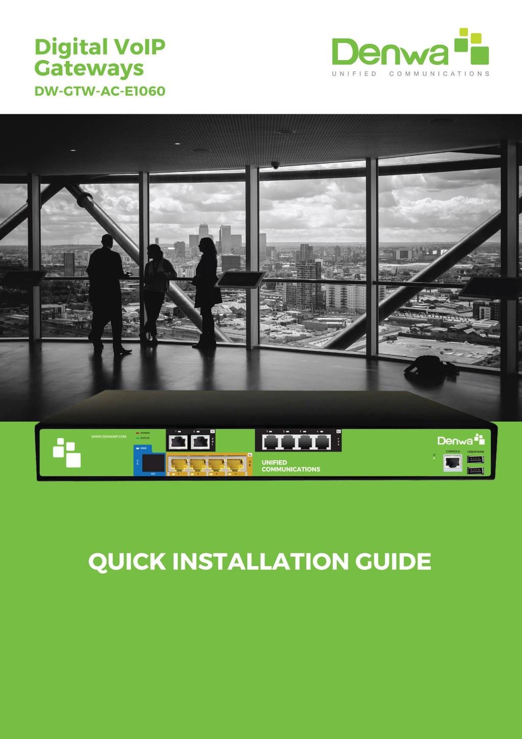
2 1 Introduction This document provides a hardware description of the DW-GTW-AC-E1060 (hereafter referred to as device) and step-by-step procedures for mounting and cabling the device. The device supports the following interfaces: 2 E1/T1 port interfaces. 4 FXS port interfaces 4 Gigabit Ethernet ports 2 Package content Follow the procedure below for unpacking the carton in which the device is shipped. DW-GTW-AC-E1060 Four anti-slide bumpers for desktop installation One FXS Lifeline cable adapter Two mounting brackets for 19-inch rack mounting One AC power cable 3 Physical Description This section provides a physical description of the device. 3.1 Physical Dimensions and Operating Environment The device's physical dimensions and operating environment are listed in the table below: Table 3-1: Physical Dimensions and Operating Environment Physical Specification Dimensions (H x W x D) Weight Environmental Description 1U x 32 x 34.5 cm (12.6 x 13.6 inches) 2.5 kg (5.5 lbs.) Operational: 5 to 40 C (41 to 104 F) Storage: -25 to 85 C (-13 to 185 F) Humidity: 10 to 90% non-condensing MTBF 238,834
3 3.2 Front Panel Description The front panel provides the telephony port interfaces, various networking ports, reset pinhole button, and LEDs. Table 3-2: Front Panel Description Item # Label Description 1 USB/WWAN USB port, used for various functionalities such as saving debug captures to a USB storage device. 2 Console Port RJ-45 to RS-232 port for serial communication. 3 POWER / STATUS LEDs indicating the status of the power and reboot/initialization. 4 PRI / Digital Telephony port interfaces that can include two E1/T1 port interfaces (RJ-48) 5 - Reset pinhole button for resetting the device and optionally, for restoring the device factory defaults. To restore the device to factory defaults, do the following: With a paper clip or any other similar pointed object, press and hold down the Reset pinhole button for at least 12 seconds, but no more than 25 seconds. 6 LAN Four 10/100/1000Base-T (Gigabit Ethernet) LAN ports for connecting IP phones, computers, or switches. These ports support the following features: Half- and full-duplex modes Auto-negotiation Straight or crossover cable detection
. These LEDs are described in the subsequent subsections. 3.2.1.")
4 ITEM Label Description Table 3-3: Rear Panel Description 1 Protective earthing screw V~4A 50-60Hz 3-Prong AC power supply entry LEDs Description The front panel provides LEDs on the device's hardware (e.g., the available telephony interfaces). These LEDs are described in the subsequent subsections LAN Interface LEDs Each LAN port provides a LED (located on its left) for indicating LAN operating status, as described in the table below. Table 3-4: LAN LEDs Description LED Color LED Staus Description Green On Ethernet link established. Flashing Data is being received or transmitted. - Off No Ethernet link E1/T1 LEDs Each trunk port provides a LED for indicating operating status, as described in the table below:
5 Table 3-5: E1/T1 LEDs Description Color State Description Green On Trunk is synchronized (normal operation). Red On Loss due to any of the following signals: LOS - Loss of Signal LOF - Loss of Frame AIS - Alarm Indication Signal (the Blue Alarm) RAI - Remote Alarm Indication (the Yellow Alarm) - Off Failure / disruption in the AC power supply or the power is currently not being supplied to the device through the AC power supply entry Operational Status LEDs The STATUS LED indicates the operating status, as described in the table below. Table 3-6: STATUS LEDs Description LED Color LED State Description Green Red On Flashing On Off The device is operational and in Standalone mode (not in High-Availability mode). Initial rebooting stage. Boot failure. Advanced rebooting stage Power LEDs The POWER LED indicates the operating status, as described in the table below. Table 3-7: POWER LEDs Description
6 LED Color LED State Description Green On Power is received by the device. - Off No power received by the device. 4 Mounting the Device The device can be mounted in one of the following ways: Placed on a desktop Installed in a standard 19-inch rack Warning: Do not place any equipment directly on top of the device or adjacent to its sides (at least 13-cm separation). In addition, if you are mounting the device in a 19-inch rack, ensure that at least a 3U separation is maintained between the device and other mounted devices or equipment.

7 4.1 Desktop Mounting The device can be placed on a desktop when its four anti-slide bumpers (supplied) are attached to the underside of the device. To attach the anti-slide rubber bumpers to the device: 1. Flip the device over so that its underside faces up. 2. Locate the four anti-slide grooves on the underside - one in each corner. 3. Peel off the adhesive, anti-slide rubber feet and stick one in each antislide groove. Figure 4-1: Rubber Foot Attached to Underside of Device 4. Flip the device over again so that it rests on the rubber feet and place it in the required position on a desktop Inch Rack Mounting The device can be installed in a standard 19-inch rack by implementing one of the following mounting methods: Placing it on a pre-installed shelf in a 19-inch rack Attaching it directly to the rack s frame using the device's mounting brackets (supplied) that need to be attached to the chassis Rack Mount Safety Instructions When installing the chassis in a rack, implement the following safety instructions: Elevated Operating Ambient Temperature: If installed in a closed or multi-unit rack assembly, the operating ambient temperature of the rack environment may be greater than room ambient temperature. Therefore, consideration should be given to installing the equipment in an environment with maximum ambient temperature (Tma) of 40 C (104 F). Reduced Air Flow: Installation of the equipment in a rack should be such that the amount of air flow required for safe operation on the equipment is not compromised. Mechanical Loading: Mounting of the equipment in the rack
8 should be such that a hazardous condition is not achieved due to uneven mechanical loading. Circuit Overloading: Consideration should be given to the connection of the equipment to the supply circuit and the effect that overloading of the circuits might have on over-current protection and supply wiring. Appropriate consideration of equipment nameplate ratings should be used when addressing this concern. Reliable Earthing: Reliable earthing of rack-mounted equipment should be maintained. Particular attention should be given to supply connections other than direct connections to the branch circuit (e.g., use of power strips) Using a Pre-installed Rack Shelf The procedure below describes how to place the device on a pre-installed shelf in a 19-inch rack. To mount the device on a pre-installed shelf in the rack: 1. Before installing it in the rack, ensure that you have a pre-installed rack shelf on which the device can be placed. 2. Place the device on the pre-installed shelf in the rack Using Mounting Brackets The procedure below describes how to mount the device in a 19-inch rack. Rack mounting involves placing the device on a pre-installed rack shelf and then attaching the device's mounting brackets (to the device and rack frame). The purpose of the mounting brackets is to secure the device to the rack. Figure 4-2: Mounting Bracket (Right) Note: 19-inch rack mounting using mounting brackets is a customer ordered feature.
9 To mount the device in a 19-inch rack using mounting brackets: 1. Attach the two mounting brackets (supplied) to each side of the device's chassis, using the supplied screws, as shown in the figure below: Figure 4-3: Attaching the Mounting Brackets 2. Place the device on a pre-installed shelf in the rack. 3. Attach the ends of the mounting brackets (that you installed in Step 1) to the vertical track of the rack's frame, using standard 19-inch rack bolts (not supplied). 5 Cabling the Device This chapter describes the cabling of the device. 5.1 Grounding and Surge Protection The device must be connected to earth (grounded) using an equipment-earthing conductor. Protective Earthing The equipment is classified as Class I EN60950 and UL60950 and must be earthed at all times. For Finland: "Laite on liltettava suojamaadoituskoskettimilla varustettuun pistorasiaan." For Norway: "Apparatet rna tilkoples jordet stikkontakt." For Sweden: "Apparaten skall anslutas till jordat uttag." Grounding and Power Surge Protection
10 The device must be installed only in telecommunication sites / centers in compliance with ETS requirements "Earthing and Bonding of Telecommunication Equipment in Telecommunication Centers". Prior to installation, earth loop impedance test must be performed by a certified electrician to ensure grounding suitability at the power outlet intended to feed the unit. It is essential that the impedance will be kept below 0.5 ohms! Proper grounding is crucial to ensure the effectiveness of the lightning protection, connect the device permanently to ground (as described in the procedure below). The device's grounding screw must be connected to the equipotential grounding bus bar located in the Telecommunication rack or installation site, using a wire of 6 mm2 surface wire. If the device is installed in a rack with other equipment, the rack must be connected to the equipotential grounding bus bar of the Telecommunication room, using a stranded cable with surface area of 25 mm2. The length of this cable must be as short as possible (no longer than 3 meters). Failing to install primary surge protectors and failing to comply with the grounding instructions or any other installation instructions, may cause permanent damage to the device. As most of the installation is the responsibility of the customer, Denwa Corp can assume responsibility for damage only if the customer can establish that the device does not comply with the standards specified above (and the device is within the hardware warranty period). The device complies with protection levels as required by EN 55024/EN Higher levels of surges may cause damage to the device.
 to the chassis' grounding screw (located on the rear panel), using the supplied washer and fasten the wire securely using a 6-32 UNC")
11 To ground the device: 1. Connect an electrically earthed strap of 16 AWG wire (minimum) to the chassis' grounding screw (located on the rear panel), using the supplied washer and fasten the wire securely using a 6-32 UNC screw. Figure 5-1: Grounding the Device 2. Connect the other end of the strap to a protective earthing. This should be in accordance with the regulations enforced in the country of installation. 5.2 ISDN E1/T1 Interfaces This section describes how to cable the PRI interfaces Connecting to ISDN PRI (E1/T1) Trunks The procedure below describes the cabling of the device's E1/T1 (PRI) trunk interfaces. Warning: To protect against electrical shock and fire, use a 26 AWG min wire to connect T1 or E1 ports to the PSTN. To comply with EMC rules and regulations, use shielded twisted pair (STP) cables for E1 interfaces on DW-GTW-AC-E1060. Note: PRI interfaces are a customer-ordered item.

12 Cable specifications: Cable: STP cable of 26 AWG min. Connector Type: RJ-48c Connector Pinouts: Figure 5-14: RJ-48c Connector Pinouts for E1/T1 To connect the E1/T1 trunk interface: 1. Connect the E1/T1 trunk cable to the device s E1/T1 port. 2. Connect the other end of the trunk cable to your PBX/PSTN switch. Figure 5-15: Cabling E1/T1 Ports Notes: It does not matter which PRI port connects to which Tel entity (i.e., PBX or PSTN). To enable PSTN Fallback upon IP network connectivity issues, use

13 the TrunkLifeLineType parameter (PSTN Fallback upon power outage is done by default). 5.3 Connecting to a Computer for Serial Communication The device provides an RS-232 serial interface port on its front panel for serial communication with a PC. Port Type: RJ-45 Cable: RJ-45 to DB-9 To connect the device's serial interface to a computer: a. Connect the RJ-45 cable connector to the device's serial port, labeled CONSOLE. b. Connect the other end of the cable to the COM1 or COM2 RS-232 communication port on your PC. Figure 5-19: Cabling Serial Interface (RJ-45) 5.4 Powering up the Device The device receives power from a standard alternating current (AC) electrical outlet. The connection is made using the supplied AC power cord. Table 5-3: Power Specifications Physical Specification Input Voltage AC Input Frequency AC Input Current Value Single universal AC power supply 100 to 240V 50 to 60 Hz 1.5 A Max. Power Consumption Gateway (without OSN): 60W* Warnings: The device must be connected to a socket-outlet providing a protective earthing connection. Use only the AC power cord that is supplied with the device.

14 To connect the device to the power supply: 1. Connect the line socket of the AC power cord (supplied) to the device's AC power socket (labeled V ~ 4A 50-60Hz), located on the rear panel. Figure 5-21: Connecting to the Power Supply outlet. 2. Connect the plug at the other end of the AC power cord to a standard electrical Once you have cabled and powered-up the device, the POWER LED on the front panel lights up green. 6 Maintenance Replacing the Power Fuse The device contains a fuse that protects the device from excessive current. The fuse is located on the rear panel, below the power socket. To replace the fuse, use only one of the following fuses described in the table below: Table 6-1: Allowed Fuses for the Device Manufacturer BEL Manufacturer Part Number 5ET2.5-R CONQUER UDL 2.50 LITTEFUSE MXP Caution For continuous protection, replace only with the same fuse type and rating fuse.


15 To replace the fuse: 1. Unplug the power cord from the electrical outlet. 2. Using a small flathead screwdriver, gently pries open the fuse cavity as illustrated in the figure below: Figure 6-1: Opening the Fuse Cavity 3. Carefully remove the fuse from the fuse cavity. Figure 6-2: Removed Power Fuse 4. Insert the new fuse securely into the fuse cavity until you hear a click sound. 5. Reconnect the power cord and verify that the Power LED is lit green.
Hardware Installation Manual
 Mediant TM 600 VoIP Media Gateway SIP Protocol Hardware Installation Manual Version 6.6 April 2012 Document #: LTRT-85609 Hardware Installation Manual Contents Table of Contents 1 Introduction... 7 2
Hardware Installation Manual. AudioCodes Mediant Family of Session Border Controllers. Mediant 500. Enterprise Session Border Controller (E-SBC)
") Hardware Installation Manual AudioCodes Mediant Family of Session Border Controllers Mediant 500 Enterprise Session Border Controller (E-SBC) Hardware Installation Manual Contents Table of Contents 1
Hardware Installation Manual AudioCodes Mediant Family of Session Border Controllers Mediant 500 Enterprise Session Border Controller (E-SBC) Hardware Installation Manual Contents Table of Contents 1
Mediant 800 Gateway and E-SBC
 Mediant 800 Gateway and E-SBC Quick Setup Guide Welcome Congratulations on purchasing your AudioCodes Mediant 800 Gateway and Enterprise Session Border Controller (E-SBC), hereafter, referred to as the
Hardware Installation Manual. AudioCodes Mediant Family of Enterprise Session Border Controllers (E-SBC) Mediant 500 E-SBC
 Mediant 500 E-SBC") Hardware Installation Manual AudioCodes Mediant Family of Enterprise Session Border Controllers (E-SBC) Mediant 500 E-SBC Hardware Installation Manual Contents Table of Contents 1 Introduction... 11 2
Hardware Installation Manual AudioCodes Mediant Family of Enterprise Session Border Controllers (E-SBC) Mediant 500 E-SBC Hardware Installation Manual Contents Table of Contents 1 Introduction... 11 2
MediaPack TM Series. MP-11x & MP-124. Analog VoIP Gateways. Installation Manual. Version 6.6. April 2012 Document #: LTRT-59815
 MediaPack TM Series MP-11x & MP-124 Analog VoIP Gateways Installation Manual Version 6.6 April 2012 Document #: LTRT-59815 Hardware Installation Manual Contents Table of Contents 1 Introduction... 7 2
Hardware Installation Manual
 Mediant TM 2000 VoIP Media Gateway SIP Protocol Hardware Installation Manual Version 6.4 October 2011 Document # LTRT-70116 Hardware Installation Manual Contents Table of Contents 1 Introduction... 7
Hardware Installation Manual. AudioCodes Family of Multi-Service Business Routers (MSBR) Mediant 500 MSBR
 Mediant 500 MSBR") Hardware Installation Manual AudioCodes Family of Multi-Service Business Routers (MSBR) Mediant 500 MSBR Hardware Installation Manual Contents Table of Contents 1 Introduction... 11 2 Unpacking the Device...
Hardware Installation Manual AudioCodes Family of Multi-Service Business Routers (MSBR) Mediant 500 MSBR Hardware Installation Manual Contents Table of Contents 1 Introduction... 11 2 Unpacking the Device...
Hardware Installation Manual. AudioCodes Multi-Service Business Routers (MSBR) Mediant 800 MSBR
 Mediant 800 MSBR") Hardware Installation Manual AudioCodes Multi-Service Business Routers (MSBR) Mediant 800 MSBR Hardware Installation Manual Contents Table of Contents 1 Introduction... 11 2 Unpacking the Device... 13
Hardware Installation Manual AudioCodes Multi-Service Business Routers (MSBR) Mediant 800 MSBR Hardware Installation Manual Contents Table of Contents 1 Introduction... 11 2 Unpacking the Device... 13
Hardware Installation Manual
 Mediant 800 MSBG Multi-Service Business Gateway SIP Protocol Hardware Installation Manual Version 6.4 October 2011 Document # LTRT-10206 Hardware Installation Manual Contents Table of Contents 1 Introduction...
Mediant 800 Media Gateway & Enterprise SBC
 Hardware Installation Manual AudioCodes Mediant Family of Media Gateways & Session Border Controllers (SBC) Mediant 800 Media Gateway & Enterprise SBC Hardware Installation Manual Contents Table of Contents
Mediant 800 Media Gateway & Enterprise SBC
 Hardware Installation Manual AudioCodes Mediant Family of Media Gateways & Session Border Controllers (SBC) Mediant 800 Media Gateway & Enterprise SBC Hardware Installation Manual Contents Table of Contents
Cisco CRS 3-Phase AC Power Distribution Unit Installation Guide 2. Cisco CRS 3-Phase AC Power Distribution Unit 2
 Cisco CRS 3-Phase AC Power Distribution Unit Installation Guide Cisco CRS 3-Phase AC Power Distribution Unit Installation Guide 2 Cisco CRS 3-Phase AC Power Distribution Unit 2 Revised: November 18, 2016,
Hardware Installation Manual
 Mediant 850 MSBR Multi-Service Business Router SIP Protocol Hardware Installation Manual Version 6.6 February 2013 Document #: LTRT-10281 Hardware Installation Manual Contents Table of Contents 1 Introduction...
Hardware Installation Manual. AudioCodes Mediant Family of Media Gateways & Session Border Controllers. Mediant 800B. Media Gateway & Enterprise SBC
 Hardware Installation Manual AudioCodes Mediant Family of Media Gateways & Session Border Controllers Mediant 800B Media Gateway & Enterprise SBC Hardware Installation Manual Contents Table of Contents
Mediant 1000B Survivable Branch Appliance (SBA) for Microsoft Skype for Business
 for Microsoft Skype for Business") Mediant 1000B Survivable Branch Appliance (SBA) for Microsoft Skype for Business Quick Setup Guide Welcome Congratulations on purchasing your AudioCodes Mediant 1000B SBA (hereafter referred to as device)
Mediant 1000B Survivable Branch Appliance (SBA) for Microsoft Skype for Business Quick Setup Guide Welcome Congratulations on purchasing your AudioCodes Mediant 1000B SBA (hereafter referred to as device)
HP UPS R/T3000 G2. Overview. Precautions. Kit contents. Installation Instructions
 HP UPS R/T3000 G2 Installation Instructions Overview The HP UPS R/T3000 G2 features a 2U rack-mount with convertible tower design and offers power protection for loads up to a maximum of 3300 VA/3000 W
SBA Installation and Maintenance Manual Mediant 800B SBA for Microsoft Lync Server
 Microsoft Lync Server Survivable Branch Appliance Mediant 800B SBA SBA Installation and Maintenance Manual Mediant 800B SBA for Microsoft Lync Server Version 6.8 April 2016 Document #: LTRT-39164 Installation
Installing the Cisco AS5400XM Universal Gateway
 CHAPTER 3 Installing the Cisco AS5400XM Universal Gateway This chapter guides you through the installation of the Cisco AS5400XM universal gateway and includes the following sections: Setting Up the Chassis,
TE100-S16 16-Port 10/100Mbps Fast Ethernet Switch. User s Guide
 TE100-S16 16-Port 10/100Mbps Fast Ethernet Switch User s Guide FCC Warning This equipment has been tested and found to comply with the regulations for a Class A digital device, pursuant to Part 15 of the
Hardware Installation Manual. AudioCodes MediaPack Analog VoIP Gateways. MediaPack 11x Series MP-112, MP-114 & MP-118
 Hardware Installation Manual AudioCodes MediaPack Analog VoIP Gateways MediaPack 11x Series MP-112, MP-114 & MP-118 Hardware Installation Manual Contents Table of Contents 1 Introduction... 9 2 Unpacking
D-Link Switch User Manual. Table of Contents
 Table of Contents About This Guide... 1 Terms/Usage... 1 Copyright and Trademarks... 1 Product Introduction... 2 Package Contents... 2 Product Overview... 2 Front Panel... 2 Rear Panel... 2 Indicator LEDs...
TEG-S224TX 26-Port 10/100/1000Mbps Gigabit & Fast Ethernet Switch
 TEG-S224TX 26-Port 10/100/1000Mbps Gigabit & Fast Ethernet Switch with 2 1000BASE-T plus 24 10/100BASE-T ports User s Guide FCC Warning This equipment has been tested and found to comply with the regulations
EZ Switch EZ Connect N SMCFS1601/SMCFS2401
 EZ Switch EZ Connect N Draft 16/24-Port 11n Wireless Fast Ethernet USB2.0 Adapter Switch SMCFS1601/SMCFS2401 COPYRIGHT & TRADEMARKS Specifications are subject to change without notice. is a registered
High Power over Ethernet Midspans PD Port Model PD Port Model
 Data and Power on a Single Line High Power over Ethernet Midspans PD-8006-6 Port Model PD-8012-12 Port Model User Guide Notice The information contained herein is believed to be accurate and reliable at
HP UPS R/T3000 ERM. Overview. Precautions. Installation Instructions
 HP UPS R/T3000 ERM Installation Instructions Overview The ERM consists of two battery packs in a 2U chassis. The ERM connects directly to a UPS R/T3000 or to another ERM. Up to two ERM units can be connected.
The power behind competitiveness. Delta Infrasuite Power Management. Power Distribution Unit. User Manual.
 The power behind competitiveness Delta Infrasuite Power Management Power Distribution Unit User Manual www.deltapowersolutions.com Save This Manual This manual contains important instructions and warnings
Installation Job Aid for Ethernet Routing Switch 3600 Series
 Installation Job Aid for Ethernet Routing Switch 3600 Series Notices NN47213-303 Issue 03.01 November 2017 Notice paragraphs alert you about issues that require your attention. Following are descriptions
PD-6506, PD & PD-6524
 PD-6506, PD-6512 & PD-6524 User Guide Notice The information contained herein is believed to be accurate and reliable at the time of printing. However, due to ongoing product improvements and revisions,
Installing the Cisco 2524 and Cisco 2525 Routers
 CHAPTER 3 Installing the Cisco 2524 and Cisco 2525 Routers This chapter guides you through the installation of the Cisco 2524 and Cisco 2525 routers and includes the following sections: Required Tools
Disclaimer. Note that the Midspan is designed for indoor use only.
 Gigabit Power over Ethernet Midspans PD-6006G, PD-6012G & PD-6024G 6/12/24-Port Models IEEE 802.3af-compliant User Guide Notice The information contained herein is believed to be accurate and reliable
Hardware Installation Manual
 Mediant 1000B MSBR Multi-Service Business Router SIP Protocol Hardware Installation Manual Hardware Installation Manual Contents Table of Contents 1 Introduction... 11 2 Unpacking the Device... 13 3 Physical
HP R/T2200 UPS. Overview. Precautions. Installation Instructions. The HP UPS R/T2200 features power protection for loads up to 2200 VA/1600 W.
 HP R/T2200 UPS Installation Instructions Overview The HP UPS R/T2200 features power protection for loads up to 2200 VA/1600 W. For more information about any of the topics covered in this document, see
User Guide TL-SG1024D 24-Port Gigabit Desktop/Rackmount Switch
 User Guide TL-SG1024D 24-Port Gigabit Desktop/Rackmount Switch Rev: 1.0.0 7106503213 COPYRIGHT & TRADEMARKS Specifications are subject to change without notice. is a registered trademark of TP-LINK TECHNOLOGIES
MediaPack 124 (MP-124)
") Hardware Installation Manual AudioCodes MediaPack 1xx Family of Analog Media Gateways MediaPack 124 (MP-124) Hardware Installation Manual Contents Table of Contents 1 Introduction... 9 2 Unpacking the
Hardware Installation Manual AudioCodes MediaPack 1xx Family of Analog Media Gateways MediaPack 124 (MP-124) Hardware Installation Manual Contents Table of Contents 1 Introduction... 9 2 Unpacking the
Omnitron Systems Technology, Inc. 1. iconverter. 19-Module Managed Power Chassis User s Manual
 Omnitron Systems Technology, Inc. 1 iconverter 19-Module Managed Power Chassis User s Manual 27 Mauchly, #201, Irvine, CA 92618 Phone: (949) 250-6510; Fax: (949) 250-6514 2 Omnitron Systems Technology,
Handset Charging Rack OpenStage WL 3 / OpenStage WL3 Plus. Installation Guide A31003-M2000-J
 Handset Charging Rack OpenStage WL 3 / OpenStage WL3 Plus Installation Guide A31003-M2000-J102-2-7631 Our Quality and Environmental Management Systems are implemented according to the requirements of the
Allworx 24x Service and Troubleshooting Guide
 Allworx 24x Service and Troubleshooting Guide -PAGE INTENTIALLY LEFT BLANK- Table of Contents 1 Safety Instructions...1 1.1 Electrical...1 1.2 Electrostatic Discharge...1 2 Chassis Views...2 3 Exterior
MediaPack 1xx Analog VoIP Gateway
 MediaPack 1xx Analog VoIP Gateway Quick Setup Guide Welcome Congratulations on purchasing your AudioCodes MediaPack 1xx (MP-1xx) Analog Voice-over-IP (VoIP) Media Gateway (hereafter, referred to as device)!
Quick Start Guide. C-100 Series Switches
 Quick Start Guide C-100 Series Switches C-100 SERIES QUICK START GUIDE Warnings and Cautionary Messages!! Warning: This product does not contain any serviceable user parts. Warning: Installation and removal
Dell Networking S4810 Open Networking (ON) Getting Started Guide
 Getting Started Guide") Dell Networking S4810 Open Networking (ON) Getting Started Guide Regulatory Model: S4810 Notes, Cautions, and Warnings NOTE: A NOTE indicates important information that helps you make better use of your
Dell Networking S4810 Open Networking (ON) Getting Started Guide Regulatory Model: S4810 Notes, Cautions, and Warnings NOTE: A NOTE indicates important information that helps you make better use of your
User Manual. Per Port Monitoring Models
 User Manual Per Port Monitoring Models Table of Contents 1. Introduction... 1 2. Package Contents... 2 3. Function... 3 4. Installation... 5 5. Web Interface... 6 1. Introduction The ServerLink Per Port
Junos WebApp Secure 5.0 Hardware Guide
 Junos WebApp Secure 5.0 Hardware Guide Junos WebApp Secure 5.0 Hardware Guide This document contains a specification for the MWS1000 hardware appliance, as well as instructions for installation into a
TA Series Analog VoIP Gateway Installation Guide
 TA Series Analog VoIP Gateway Installation Guide Version 1.5 Date: November 17, 2016 Yeastar Information Technology Co. Ltd. Contents About TA Series Analog VoIP Gateway... 3 1. Preparation before Installation...
Yeastar S100 VoIP PBX
 Yeastar S100 VoIP PBX Installation Guide Version: 1.1 Date: 2016/7/6 Content Welcome...3 Before You Start..4 Package Contents.4 Expansion Board 4 Yeastar S100 Overview...5 LED Indicators and Ports..6 Installation...8
Installation Note for the Cisco ME 3800X and ME 3600X Switch Power Supply and Fan Modules
 Installation Note for the Cisco ME 3800X and ME 3600X Switch Power Supply and Fan Modules This document provides the installation and removal instructions for the AC and DC input power supply and fan modules
iconverter 2-Module Power Chassis
 iconverter 2-Module Power Chassis User Manual 38 Tesla, Irvine, CA 92618 USA Phone: (949) 250-6510; Fax: (949) 250-6514 Page 1 Warning The operating description in this Instruction Manual is for use by
Yeastar S300 VoIP PBX. Installation Guide
 Yeastar S300 VoIP PBX Installation Guide Version 1.0 Jun. 2016 Content Content...2 Welcome.3 Before You Start...4 Package Contents..4 Expansion Board 4 Yeastar S300 Overview.5 LED Indicators and Ports..6
100 - SERIES NETWORK SWITCHES QUICK START GUIDE
 100 - SERIES NETWORK SWITCHES QUICK START GUIDE Unmanaged AV Rack Network Switches FCC Warning This device has been tested and found to comply with limits for a Class A digital device, pursuant to Part
Cisco ONS CL Shelf Assembly Hardware
 CHAPTER 1 This chapter provides a description of Cisco ONS 15310-CL shelf hardware. Instructions for installing equipment are provided in the Cisco ONS 15310-CL and Cisco ONS 15310-MA Procedure Guide.
Installing the Cisco ATA
 CHAPTER 2 This section provides instructions for installing the Cisco ATA 186 and Cisco ATA 188. Before you perform the installation, be sure you have met the following prerequisites: Planned the network
AT-GS950/16 AT-GS950/24
 Gigabit Ethernet Smart Switches AT-GS950/16 AT-GS950/24 Installation Guide 613-000190 Rev. B Copyright 2007 Allied Telesis, Inc. All rights reserved. No part of this publication may be reproduced without
100 - SERIES NETWORK SWITCHES Installation Manual
 100 - SERIES NETWORK SWITCHES Installation Manual Unmanaged IT Rack Network Switches CERTIFICATIONS AND WARNINGS FCC Warning CE Warning UL This device has been tested and found to comply with limits for
GSW-1657 GSW User's Guide. 16/24-port Gigabit Ethernet Switch. Ver
 GSW-1657 GSW-2457 User's Guide 16/24-port Gigabit Ethernet Switch Ver.1.0.0-0803 COPYRIGHT & TRADEMARKS Specifications are subject to change without notice. Level One is a registered trademark of Digital
LVN5200A-R2, rev. 1, Hardware Installation Guide
 LVN5200A-R2 LVN5250A-R2 LVN5200A-R2, rev. 1, Hardware Installation Guide Customer Support Information Order toll-free in the U.S.: Call 877-877-BBOX (outside U.S. call 724-746-5500) FREE technical support
Installation Manual. Version 6.0
 Version 6.0 Document #: LTRT-85605 February 2010 Contents Table of Contents 1 Introduction... 9 2 Installing the Device... 11 2.1 Physical Description... 11 2.1.1 Front Panel... 12 2.1.2 Rear Panel...
Mediant 1000B Gateway & Enterprise SBC
 Hardware Installation Manual AudioCodes Mediant Media Gateways & Session Border Controllers (SBC) Mediant 1000B Gateway & Enterprise SBC Hardware Installation Manual Contents Table of Contents 1 Introduction...
LOOP-IP 6100 Series High Speed Ethernet Interface Unit Users Manual for: Loop-IP 6100-DS3 Loop-IP 6100-DS3R Loop-IP 6100-E3 Loop-IP 6100-E3R
 LOOP-IP 6100 Series High Speed Ethernet Interface Unit Users Manual for: Loop-IP 6100-DS3 Loop-IP 6100-DS3R Loop-IP 6100-E3 Loop-IP 6100-E3R LOOP TELECOMMUNICATION INTERNATIONAL, INC. 8F, NO. 8, HSIN ANN
User Manual Entry Line Industrial Fast Ethernet Switch 5x 10/100Base-TX
 User Manual Entry Line Industrial Fast Ethernet Switch 5x 10/100Base-TX Entry Line Fast Ethernet Switch Fast Ethernet Switch for Industrial Use Page 2/11 Table of Contents General... 3 Benefits... 3 Front
Installing the Cisco Unified Videoconferencing 3545 MCU
 CHAPTER 2 Installing the Cisco Unified Videoconferencing 3545 MCU The Cisco Unified Videoconferencing 3545 MCU works together with a Cisco Unified Videoconferencing 3545 EMP Enhanced Media Processor (EMP)
TRC-190 User s Manual
 User s Manual Edition 3.2, May 2017 www.moxa.com/product 2017 Moxa Inc. All rights reserved. User s Manual The software described in this manual is furnished under a license agreement and may be used only
Installation. Package Contents CHAPTER
 CHAPTER 2 Installation This chapter describes how to install your Catalyst 3500 XL switches and interpret the power-on self-tests (POST) that ensure proper operation. Read the topics, and perform the procedures
Perle MCR200 Installation Guide
 Perle MCR200 Installation Guide P/N 5500322-10 Introduction The Perle MCR200 Chassis is a 2 slot chassis able to accommodate up to 2 Perle Media Converter modules or 1 Media Converter Module and an MCR-MGT
Switched XPDU. 15A Model. User & Installation Manual Xtreme Power Conversion Corporation. All rights reserved.
 Switched XPDU 15A Model User & Installation Manual www.xpcc.com 2014. All rights reserved. (Rev 10/02/14) Table of Contents Introduction...4 PDU Package...4 Function...4 Interface...4 Installation...5
Installation RA5112-C-16A-C20. Basic Rack Power Distribution Unit
 Installation RA5112-C-16A-C20 Basic Rack Power Distribution Unit Contents Before You Begin........................1 Safety and grounding information..........1 How to Install the Rack PDU...............2
PIX 515/515E. PIX 515/515E Product Overview CHAPTER
 CHAPTER 4 PIX 515/515E This chapter describes how to install the PIX 515/515E, and includes the following sections: PIX 515/515E Product Overview Installing a PIX 515/515E PIX 515/515E Feature Licenses
Installation Job Aid for Ethernet Routing Switch 5900 Series
 Installation Job Aid for Ethernet Routing Switch 5900 Series Notices NN47211-301 Issue 05.01 November 2017 Notice paragraphs alert you about issues that require your attention. The following paragraphs
Table of Contents. 1. Introduction Package Contents Function Installation Web Interface... 4
 User Manual Table of Contents 1. Introduction... 1 2. Package Contents... 2 3. Function... 3 4. Installation... 2 5. Web Interface... 4 1. Introduction The ServerLink PDU is a network ready device designed
Preparing to Install the VG248
 CHAPTER 2 To ensure normal system operation, plan your site configuration and prepare your site before installation. Before installing the VG248, review these sections: Preparing the Installation Site,
300 - SERIES NETWORK SWITCHES QUICK START GUIDE
 300 - SERIES NETWORK SWITCHES QUICK START GUIDE Managed IT Rack Network Switches FCC Warning This device has been tested and found to comply with limits for a Class A digital device, pursuant to Part 15
TE100-DX16R/DX24R/DX32R 16/24/32 Ports Ethernet/Fast Ethernet Dual-Speed Stackable Hubs User s Guide
 TE100-DX16R/DX24R/DX32R 16/24/32 Ports Ethernet/Fast Ethernet Dual-Speed Stackable Hubs User s Guide Rev. 01 (JULY, 1998) 505-0100-004 Printed In Taiwan RECYCLABLE Dual-Speed Stackable Hubs User s Guide
Getting Started KX-NCP500 KX-NCP1000. Pure IP-PBX. Model No.
 Model No. Getting Started Pure IP-PBX KX-NCP500 KX-NCP1000 Thank you for purchasing a Panasonic Pure IP-PBX. Please read this manual carefully before using this product and save this manual for future
Preparing to Install the Cisco AS5350XM Universal Gateway
 CHAPTER 2 Preparing to Install the Cisco AS5350XM Universal Gateway This chapter describes the tasks you must perform before you begin to install the Cisco AS5350XM universal gateway and includes the following
Mediant 500L. Enterprise Session Border Controller (E-SBC) and Media Gateway. Hardware Installation Manual
 and Media Gateway. Hardware Installation Manual") Hardware Installation Manual AudioCodes Mediant Series of Media Gateways & Session Border Controllers Mediant 500L Enterprise Session Border Controller (E-SBC) and Media Gateway Hardware Installation
Hardware Installation Manual AudioCodes Mediant Series of Media Gateways & Session Border Controllers Mediant 500L Enterprise Session Border Controller (E-SBC) and Media Gateway Hardware Installation
Hypercable injecteur HPOE - Industrial IEEE 802.3at Gigabit PoE Injector. User Manual. v.1.0 Jun Mail :
 Industrial IEEE 802.3at Gigabit PoE Injector User Manual v.1.0 Jun-2011 FCC Warning This Equipment has been tested and found to comply with the limits for a Class A digital device, pursuant to Part 15
Obtaining Documentation and Submitting a Service Request, page xvii Safety Warnings, page xvii Safety Guidelines, page xx
 Preface Obtaining Documentation and Submitting a Service Request, page xvii Safety s, page xvii Safety Guidelines, page xx Obtaining Documentation and Submitting a Service Request For information on obtaining
4 10/100/1000T Mini-GBIC with 4 IEEE 802.3at High Power PoE Industrial Wide Temperature Switch. User Manual SISTP LRT
 4 10/100/1000T + 2 1000 Mini-GBIC with 4 IEEE 802.3at High Power PoE Industrial Wide Temperature Switch User Manual V1.0 September-2013 FCC Warning This Equipment has been tested and found to comply with
T3 Interface Converters
 MT1103A JULY 2003 MT1103A-DC T3 Interface Converters CUSTOMER SUPPORT INFORMATION Order toll-free in the U.S.: Call 877-877-BBOX (outside U.S. call 724-746-5500) FREE technical support 24 hours a day,
16Hi HARDWARE INSTALLATION GUIDE
 16Hi HRDWRE INSTLLTION GUIDE Table of Contents Section 1 Ratings....................................................................... 3 Section 2 Site Preparation................................................................
Installation Job Aid for VSP 4850GTS
 Installation Job Aid for VSP 4850GTS Notices Release 6.1.0.0 NN46251-308 Issue 02.01 November 2017 Notice paragraphs alert you about issues that require your attention. The following paragraphs describe
Leased-Line Extenders over IP
 SmartNode 2290 Series Leased-Line Extenders over IP Quick Start Guide Important This is a Class A device and is intended for use in a light industrial environment. It is not intended nor approved for use
Lightspeed Advanced Reporting Bottle Rocket Hardware Installation Guide
 Lightspeed Advanced Reporting Bottle Rocket Hardware Installation Guide 1800 19th Street / Bakersfield, CA 93301 / Tel: 661.716.7600 / Toll Free: 877.447.6244 / www.lightspeedsystems.com Table of Contents
Product names mentioned in this manual may be trademarks or registered trademarks of those products.
 FCC Statement The FCC (Federal Communications Commission) restricts the amount of radio frequency emission and radiation coming from computer equipment. The equipment introduced in this manual has been
SYSTIMAX 360 ipatch Network Manager Module Faceplate Instructions
 Instruction Sheet 860508340 SYSTIMAX Solutions SYSTIMAX 360 ipatch Network Manager Module Faceplate Instructions General The SYSTIMAX 360 ipatch Network Manager module is a SYSTIMAX approved product. This
USER GUIDE. EZ Switch TM 10/100 16/24-Port Unmanaged Fast Ethernet Switches SMCFS1601/SMCFS2401
 USER GUIDE EZ Switch TM 10/100 16/24-Port Unmanaged Fast Ethernet Switches SMCFS1601/SMCFS2401 EZ Switch TM 10/100 User Guide From SMC s EZ line of low-cost workgroup LAN solutions 20 Mason Irvine, CA
User Manual. AN A GPON Optical Network Unit. Version: A. Code: MN Date: December 2011
 An Expert in Optical Communications User Manual AN5506-01-A GPON Optical Network Unit Version: A Code: MN000000943 Date: December 2011 FiberHome Telecommunication Technologies Co., Ltd. Version Version
Installation and Maintenance
 CHAPTER 4 Installation and Maintenance Revised: April 19, 2010, Introduction This chapter explains how to install a SCE 1000 platform in a rack or in a general tabletop or workbench installation. Additionally,
Overview. Features CHAPTER
 CHAPTER 2 This chapter provides these topics that describe the Catalyst 2955 switch, hereafter referred to as the switch. Features, page 2-1 Front-Panel Description, page 2-3 Rear-Panel Description, page
RMB Peripheral Units Installation Guide
 RMB Peripheral Units Installation Guide Part Number 65-000101 2011 by Kentrox, Inc. All rights reserved. Copyright 2011 by Kentrox, Inc. All Rights Reserved. The material discussed in this publication
Gigabit Ethernet Switch With 10G Uplinks. Hardware Manual MS400860M
 Gigabit Ethernet Switch With 10G Uplinks Hardware Manual MS400860M Gigabit Ethernet Switch with 10G Uplinks Hardware Manual II About This Guide Purpose Audience Conventions This guide details the hardware
AX3000 Platine Terminal Ethernet TCP/IP
 AX3000 Platine Terminal Ethernet TCP/IP Model 80 Installation Guide January 2012 - Ref: I80E0922-2 Model AX3000/M80 Type EA The reproduction of this material, in part or whole, is strictly prohibited.
Installing and Removing SDRAM and DRAM
 CHAPTER 4 This chapter explains how to remove and replace the main memory modules on the network processing engine or network services engine. For the location of the memory module you are replacing, find
Mediant 1000B Gateway & Enterprise SBC
 Hardware Installation Manual AudioCodes Media Gateway & Session Border Controller (SBC) Series Mediant 1000B Gateway & Enterprise SBC Hardware Installation Manual Contents Table of Contents 1 Introduction...
User Manual Entry Line Industrial Gigabit Ethernet High Power 60/95 W PoE Injector
 User Manual Entry Line Industrial Gigabit Ethernet High Power 60/95 W PoE Injector Gigabit Ethernet Switch with PoE+ for Industrial Use Page 2/11 Table of Contents General... 3 Benefits... 3 Front View...
STATUS Shiloh Road Alpharetta, Georgia (770) FAX (770) Toll Free
 FAX (770) Toll Free") Instruction Manual Model 1582-45L Data Switch September 2010, Rev A REMOTE LOCAL SWITCH STATUS SELECT REMOTE LOCAL LOCAL SELECT CHANNEL SELECT POWER MODEL 1582 SWITCH CROSS TECHNOLOGIES, INC. Data, drawings,
Instruction Manual Model 1582-45L Data Switch September 2010, Rev A REMOTE LOCAL SWITCH STATUS SELECT REMOTE LOCAL LOCAL SELECT CHANNEL SELECT POWER MODEL 1582 SWITCH CROSS TECHNOLOGIES, INC. Data, drawings,
Installing the IPS 4345 and IPS 4360
 CHAPTER 4 Installing the IPS 4345 and IPS 4360 Contents This chapter describes the Cisco IPS 4345 and the IPS 4360, and includes the following sections: Installation Notes and Caveats, page 4-1 Product
IKS-G6524A/G6824A Series Quick Installation Guide
 IKS-G6524A/G6824A Series Quick Installation Guide Edition 3.0, February 2017 Technical Support Contact Information www.moxa.com/support Moxa Americas: Toll-free: 1-888-669-2872 Tel: 1-714-528-6777 Fax:
Installation Job Aid for VSP 4450GTX-HT- PWR+
 Installation Job Aid for VSP 4450GTX-HT- PWR+ Notices Release 6.1.0.0 NN46251-305 Issue 02.01 November 2017 Notice paragraphs alert you about issues that require your attention. The following paragraphs
PIX 520. PIX 520 Product Overview CHAPTER
 CHAPTER 5 PIX 520 This chapter guides you through the installation of the PIX 520, and includes the following sections: PIX 520 Product Overview, page 5-1 Installing the PIX 520, page 5-4 PIX 520 Feature
Industrial 5-Port Fast Ethernet Switches with SFP Slot and optional 4 PoE PSE Ports. Basic Model: KSD-541 PoE Model: KSD-541-P. Installation Guide
 Industrial 5-Port Fast Ethernet Switches with SFP Slot and optional 4 PoE PSE Ports Basic Model: KSD-541 PoE Model: KSD-541-P Installation Guide DOC.080104-1- (C) 2008 KTI Networks Inc. All rights reserved.
hp uninterruptible power system r12000 xr models installation instructions
 hp uninterruptible power system r000 xr models installation instructions Overview These instructions show how to install an uninterruptible power system (UPS). For detailed information about the UPS, refer