RH-6SDH/12SDH/18SDH/20SDH Series RH-3SDHR series
|
|
|
- Lilian Cobb
- 5 years ago
- Views:
Transcription
1 Mitsubishi Industrial Robot RH-6SDH/12SDH/18SDH/20SDH Series RH-3SDHR series Standard Specifications Manual (CR1DA/CR2DA/CR3D-700 series Controller) BFP-A8658-AB
2
3 Safety Precautions Always read the following precautions and the separate "Safety Manual" before starting use of the robot to learn the required measures to be taken. CAUTION CAUTION WARNING CAUTION WARNING CAUTION CAUTION CAUTION All teaching work must be carried out by an operator who has received special training. (This also applies to maintenance work with the power source turned ON.) Enforcement of safety training For teaching work, prepare a work plan related to the methods and procedures of operating the robot, and to the measures to be taken when an error occurs or when restarting. Carry out work following this plan. (This also applies to maintenance work with the power source turned ON.) Preparation of work plan Prepare a device that allows operation to be stopped immediately during teaching work. (This also applies to maintenance work with the power source turned ON.) Setting of emergency stop switch During teaching work, place a sign indicating that teaching work is in progress on the start switch, etc. (This also applies to maintenance work with the power source turned ON.) Indication of teaching work in progress Provide a fence or enclosure during operation to prevent contact of the operator and robot. Installation of safety fence Establish a set signaling method to the related operators for starting work, and follow this method. Signaling of operation start As a principle turn the power OFF during maintenance work. Place a sign indicating that maintenance work is in progress on the start switch, etc. Indication of maintenance work in progress Before starting work, inspect the robot, emergency stop switch and other related devices, etc., and confirm that there are no errors. Inspection before starting work
4 The points of the precautions given in the separate "Safety Manual" are given below. Refer to the actual "Safety Manual" for details. CAUTION CAUTION CAUTION CAUTION CAUTION CAUTION WARNING WARNING CAUTION WARNING CAUTION CAUTION CAUTION CAUTION WARNING Use the robot within the environment given in the specifications. Failure to do so could lead to a drop or reliability or faults. (Temperature, humidity, atmosphere, noise environment, etc.) Transport the robot with the designated transportation posture. Transporting the robot in a non-designated posture could lead to personal injuries or faults from dropping. Always use the robot installed on a secure table. Use in an instable posture could lead to positional deviation and vibration. Wire the cable as far away from noise sources as possible. If placed near a noise source, positional deviation or malfunction could occur. Do not apply excessive force on the connector or excessively bend the cable. Failure to observe this could lead to contact defects or wire breakage. Make sure that the workpiece weight, including the hand, does not exceed the rated load or tolerable torque. Exceeding these values could lead to alarms or faults. Securely install the hand and tool, and securely grasp the workpiece. Failure to observe this could lead to personal injuries or damage if the object comes off or flies off during operation. Securely ground the robot and controller. Failure to observe this could lead to malfunctioning by noise or to electric shock accidents. Indicate the operation state during robot operation. Failure to indicate the state could lead to operators approaching the robot or to incorrect operation. When carrying out teaching work in the robot's movement range, always secure the priority right for the robot control. Failure to observe this could lead to personal injuries or damage if the robot is started with external commands. Keep the jog speed as low as possible, and always watch the robot. Failure to do so could lead to interference with the workpiece or peripheral devices. After editing the program, always confirm the operation with step operation before starting automatic operation. Failure to do so could lead to interference with peripheral devices because of programming mistakes, etc. Make sure that if the safety fence entrance door is opened during automatic operation, the door is locked or that the robot will automatically stop. Failure to do so could lead to personal injuries. Never carry out modifications based on personal judgments, or use nondesignated maintenance parts. Failure to observe this could lead to faults or failures. When the robot arm has to be moved by hand from an external area, do not place hands or fingers in the openings. Failure to observe this could lead to hands or fingers catching depending on the posture.


 confirmed by manufacturer.")

 cannot be performed. C.Notes of the basic component are shown.")
5 CAUTION CAUTION CAUTION Do not stop the robot or apply emergency stop by turning the robot controller's main power OFF. If the robot controller main power is turned OFF during automatic operation, the robot accuracy could be adversely affected. Moreover, it may interfere with the peripheral device by drop or move by inertia of the arm. Do not turn off the main power to the robot controller while rewriting the internal information of the robot controller such as the program or parameters. If the main power to the robot controller is turned off while in automatic operation or rewriting the program or parameters, the internal information of the robot controller may be damaged. Use the network equipments (personal computer, USB hub, LAN hub, etc) confirmed by manufacturer. The thing unsuitable for the FA environment (related with conformity, temperature or noise) exists in the equipments connected to USB, RS-232 or LAN. When using network equipment, measures against the noise, such as measures against EMI and the addition of the ferrite core, may be necessary. Please fully confirm the operation by customer. Guarantee and maintenance of the equipment on the market (usual office automation equipment) cannot be performed. C.Notes of the basic component are shown. *SD series: CR1DA-700 series CAUTION Please install the earth leakage breaker in the primary side supply power supply of the controller because of leakage protection. CR1DA series Controller コントローラ earth leakage 漏電遮断器 breaker (NV) Cover 端子カバー Terminal 電源端子台 Cover 端子カバー 保護アース端子 (PE) Earth アース接続ネジ screw
6 *SD series: RH-6SDH/12SDH/18SDH/20SDH series/rh-3sdhr series CAUTION Be careful of interference with peripheral equipment. Especially don't give a shock to the ball screw shaft (J3 axis). The ball screw shaft may be damaged. Collision detection function is valid condition for both of automatic and jog operation at shipping in RH- 3SDHR series. However, damage to the ball screw shaft cannot be prevented completely. Refer to the separate instruction manual "Detailed explanations of functions and operations" for collision detection function. Take care also of the following items. (1)The robot's locus of movement may change with specified speed. Especially as for the corner section, short cut distance may change. Therefore, when beginning automatic operation, moves at low speed at first, and you should gather speed slowly with being careful of interference with peripheral equipment. Short cut Arch movement (example) (2)It can be confirmed whether the specified position exist in the defined area by using the instruction command "ZONE". It can utilize as one of the methods for collision evasion. Refer to the "detailed description of the instructions manual/function, and operation" of the separate volume for the details of the instruction command. CAUTION Don't give a shock to the ball screw shaft at the time of hand installation. Especially don't strike the shaft end by hammer etc. The ball screw shaft may be damaged.
7 Revision history Date of print Specifications No. Details of revisions BFP-A8658 First print BFP-A8658-A The example of filter installation to the servo amplifier for addition axes was added. CE Marking specification was added BFP-A8658-B Difference of connector assignment of of sink and source type of parallel I/O interface/ unit were added BFP-A8658-C EC Declaration of Conformity were added BFP-A8658-D Correct description of the "S" number in the robot type. Add the type of the caster specification controller. flange was changed into mechanical interface The description of the fretting was corrected. The example of emergency stop connection of the example of safety measures was improved. Functional description of the enabling device was improved BFP-A8658-E The following expressions were corrected Special specifications, Options, Maintenance parts, 1.2 Model type name of robot, 1.5 Instruction manuals, Robot arm, Extended machine cable(table 1-3), Hand output cable(table 1-3), Hand input cable(table 1-3), CC-Link interface(table 1-3), Controller specification with countermeasure against oil mist(table 1-3), Recommendation article of the USB cable, Protection specifications, (1)Machine cable(special specifications and option), Table 3-1 Standard specifications of controller, The operation lock of the power switch, The following errors in writing were corrected, Stopper for changing the operating range of the J1 axis(table 1-3),, Caster specifications controller(table 1-3), The following was added Serial encoder interface(table 3-1), BFP-A8658-F Additional Axis Function and Tracking Function Manual were added to the product configuration of Instruction Manual. The English expression was corrected. Safety Precautions, Special specifications, Table 1.3: The list of Option equipment and special specification, Caution of USB devices, Shipping special specifications, Examples of safety measures Parameter AREA*CS was added BFP-A8658-G The examples of safety measures ( Wiring example 3 ~ 5 ) were corrected BFP-A8658-H The figure of key switch in "3.6.3 Door switch function " was corrected. (Error in writing) The figure of example of safety measures in "6.1.7 Examples of safety measures " was corrected. (connects the enabling switch) The EC Declaration of Conformity was changed. (Correspond to the EMC directive; 2006/42/EC) BFP-A8658-J Fuse rating of pneumatic hand interface (RZ365/375) was corrected. The text of "This interface is pre-installed on the controller" in pneumatic hand interface was deleted BFP-A8658-K The example of connection with the Mitsubishi sequencer of Parallel I/O unit was changed into Q series. Pressure of the dry air for pressurization was corrected. The type which lengthened the J3 axis (Z) stroke was added. RH-6SDQH3532/4532/5532, RH-6SDQH3527C/4527C/5527C, RH-6SDQH3527M/4527M/5527M RH-12SDQH5545/7045/8545, RH-12SDQH5538C/7038C/8538C, RH-12SDQH5538M/7038M/8538M BFP-A8658-L CE specification of the CR1DA controller was added. Error in writing was corrected BFP-A8658-M Explanation of the new RH-20SDH series was added. The type name of robot controller was changed with specification change.(cr1d to CR1DA, CR2D to CR2DA) BFP-A8658-N Cover packing was added to the consumable part. The description of protection specification was changed. (The cutting oil which examined was updated, and replacement of the cover packing was added) EC Declaration of Conformity were added BFP-A8658-P The input voltage range of the CR2DA controller was corrected. ("3-phase, AC180 to 253" was the previous.) BFP-A8658-Q The RH-3SDHR3515 was added. The dimensions of the hole which draws the power cable were added (CR2DA controller). The type name optional of hand input cable and hand curl tube for RH-20SDH100** series was changed. The EC Declaration of Conformity were added.
8 Date of print Specifications No. Details of revisions BFP-A8658-R The EC Declaration of Conformity were added BFP-A8658-S The coupling for air purge in figure of "Wiring and piping for hand (RH-3SDHR)" was deleted. (error in writing). The type name of optional hand input cable for RH-3SDHR was changed BFP-A8658-T The sink / source expression of pin assignment of hand input cable was corrected. (Sink / Source are common) The type name of optional hand curl tube for RH-20SDH100** series was changed. The hand curl tube outline drawing was corrected. (Error in writing) BFP-A8658-U The outside dimension of CR1DA controller (CE marking specification) was changed. The rear cover of the CR1DA controller was made unnecessary. Ball screw protective measures were added. The note about temperature of the air to supply for hand was added. Part code was added to the consumable part BFP-A8658-V Hand output junction cable was added to the solenoid valve set optional. (RH-6SDH/ 12SDH/18SDH/20SDH series) Table 1-5: Recommendation article of the USB cable was corrected BFP-A8658-W The user's guide was added based on South Korean Radio Law. Fuse rating of pneumatic hand interface (RZ365/375) was corrected. (error in writing). The setting value range of parameter SFC*ME and AREA*ME were corrected. (error in writing) BFP-A8658-X The note about the connection of the emergency stop was added. The automatic compensation graph of the RH-6SDH's Z-stroke-200mm in "Automatic compensation of acceleration/deceleration speed" was corrected. (Clarified. With no change in acceleration/deceleration speed rate) The signal assignment list of parallel I/O interface and parallel I/O unit were corrected. (Assignment of the dedicated signal was added) BFP-A8658-Y The EC Declaration of Conformity were changed BFP-A8658-AA The target axis and interval of intermittent brake release were added. QJ61BT11N (Q series) was added to the master station of the CC-Link interface. The "Emergency stop output" in the controller standard specification table was deleted. (Overlapped with "Robot error output".) The "Table 3-3 : Emergency stop/door switch input" in "3.4 External input/output" was deleted. (Overlapped with "Table 3-5 : Special input/output terminal".) Error in writing in table of Standard specifications of robot was corrected. (allowable moment load -> allowable inertia) The details of hand output junction cable were added. Clean specification and waterproof (IP65) specification were added for RH-3SDHR series. The EC Declaration of Conformity were changed. RH-20SDH100* was added to "2.4.7 Changing the operating range" Correction of an error in "2.5.7 About the Installation of Tooling Wiring and Piping". (formerly: Floor installation type) BFP-A8658-AB The note about the connection of the emergency stop was added. The EC Declaration of Conformity were changed. The notes about frequent installation and removal of TB and the dummy connector were added. The explanation about the controller of KC mark specification was added to " Introduction".
9 Contents Page 1 General configuration Structural equipment Standard structural equipment Special specifications Options Maintenance parts Model type name of robot How to identify the robot model (1) Floor installation type (2) Hanging installation type Combination of the robot arm and the controller CE marking specifications Indirect export Instruction manuals Contents of the structural equipment Robot arm Controller Contents of the Option equipment and special specification Robot arm Standard specifications (1) RH-6SDH series (2) RH-12SDH series (3) RH-18SDH series (4) RH-20SDH series (5) RH-3SDHR series The counter-force applied to the installation surface RH-3SDHR series installation stage (1) Example which uses the iron material (2) Example which uses the aluminum Definition of specifications Pose repeatability Rated load (mass capacity) Relationships Among Mass Capacity, Speed, and Acceleration/Deceleration Speed (1) Setting Load Capacity and Size (Hand Conditions) Vibrations at the Tip of the Arm during Low-Speed Operation of the Robot Vibration of shaft (J3 axis) position and arm end (1) Relationship Between Mass Capacity and Speed (2) Relationship Between Height of Shaft (J3 Axis) and Acceleration/Deceleration Speed (3) Time to reach the position repeatability (only for RH-12SDH/18SDH/20SDH series) About moving speed at singular point and near singular point. (RH-3SDHR series) Collision detection Protection specifications (1) Types of protection specifications (2) About the use with the bad environment Clean specifications (1) Types of clean specifications Names of each part of the robot Outside dimensions Operating range diagram Outside dimensions Operating range diagram (RH-6SDH series) (1) Standard Specification (2) Clean Specification (3) Oil mist Specification Outside dimensions Operating range diagram of RH-12SDH series (1) Standard Specification (2) Clean Specification i
10 Contents Page (3) Oil mist Specification Outside dimensions Operating range diagram of RH-18SDH series (1) Srandard Specification (2) Clean Specification (3) Oil mist Specification Outside dimensions Operating range diagram of RH-20SDH series (1) Standard Specification (2) Clean Specification (3) Oil mist Specification Outside dimensions Operating range diagram of RH-3SDHR series (1) Standard Specification (2) Clean/Waterproof Specification Mechanical interface and Installation surface (1) Mechanical interface and Installation surface of RH-6SDH series (2) Mechanical interface and Installation surface of RH-12SDH/18SDH series (3) Mechanical interface and Installation surface of RH-20SDH series (4) Mechanical interface and Installation surface of RH-3SDHR series (Standard specification) 2-73 (5) Mechanical interface and Installation surface of RH-3SDHR series (Clean/Waterproof specification) Change the operating range (1) Operating range changeable angle (2) The change method of the operating range Tooling Wiring and piping for hand Internal air piping (1) Floor installation type (2) Hanging installation type Internal wiring for the pneumatic hand output cable (1) Floor installation type (2) Hanging installation type Internal wiring for the hand check input cable (1) Floor installation type (2) Hanging installation type Spare Wiring (1) Standard type Precautions for piping to the flexible cable About the Installation of Tooling Wiring and Piping (Examples of Wiring and Piping) (1) Example of wiring and piping <1> (2) Wiring and piping example <2> (3) Precautions for the oil mist specification and clean specification (4) Precautions for the clean specification Wiring and piping system diagram for hand Electrical specifications of hand input/output Air supply circuit example for the hand Shipping special specifications, options, and maintenance parts Shipping special specifications (1) Machine cable Options (1) Machine cable extension (2) Changing the operating range (3) Solenoid valve set (4) Hand input cable (5) Hand output cable (6) Hand curl tube (7) Hand tube About Overhaul Maintenance parts ii
11 Contents Page 3 Controller Standard specifications Standard specifications Protection specifications and operating supply Names of each part (1) Padlock specification Outside dimensions/installation dimensions Outside dimensions Installation dimensions Cable lead-in and dimension External input/output Types Dedicated input/output Emergency stop input and output etc Connection of the external emergency stop Special stop input(skip) Door switch function Enabling device function (1) When door is opening (2) When door is closing (3) Automatic Operation/Jog Operation/Brake Release and Necessary Switch Settings Additional Axis Function Wiring of the Additional Axis Interface Magnet contactor control connector output (AXMC) for addition axes Options (1) Teaching pendant (T/B) (2) Pneumatic hand interface (3) Parallel I/O interface (4) External I/O cable (5) Parallel I/O unit (6) External I/O cable (7) Personal computer cable (8) CC-Link interface (9) Extension memory cassette (10) RT ToolBox2/RT ToolBox2 mini (11) Instruction Manual(bound edition) Maintenance parts Software List of commands List of parameters Instruction Manual The details of each instruction manuals Safety Safety Self-diagnosis stop functions External input/output signals that can be used for safety protection measures Precautions for using robot Safety measures for automatic operation Safety measures for teaching Safety measures for maintenance and inspections, etc Examples of safety measures (1) External emergency stop connection [supplementary explanation] Working environment iii
12 Contents Page 6.3 Precautions for handling Appendix... Appendix-223 Appendix 1 : Specifications discussion material (Floor installation specification)... Appendix-223 Appendix 2 : Specifications discussion material (Hanging installation specification)... Appendix-224 iv
13 Introduction The RH-6SDH/12SDH/18SDH/20SDH series, RH-3SDHR series offers small-size industrial robots developed using Mitsubishi's latest technology. They are especially designed to handle and assemble mechanical parts. They are Mitsubishi's answer to the customer's need to achieve a compact manufacturing facility capable of highly flexible production, as necessitated by the diffusion of high-density product groups and the shorter product life cycles that have become common-place in recent years. About RH-3SDHR series, because the installation surface does not give limitation to the operating range, it can work to the layout in the customer flexibly. However, to comply with the target application, a work system having a well-balanced robot arm, peripheral devices or robot and hand section must be structured. When creating these standard specifications, we have edited them so that the Mitsubishi robot's characteristics and specifications can be easily understood by users considering the implementation of robots. However, if there are any unclear points, please contact your nearest Mitsubishi branch or dealer. Mitsubishi hopes that you will consider these standard specifications and use our robots. The controller differ corresponding to the specification of robot. Please refer to Page 2, "1.2 Model type name of robot" or Page 4, "1.3 CE marking specifications". Note that in this specification document the specifications related to the robot arm is described Page 10, "2 Robot arm", the specifications related to the controller Page 119, "3 Controller", and software functions and a command list Page 206, "4 Software" separately. This document has indicated the specification of the following types robot. On floor type... *RH-6SDH series *RH-12SDH series *RH-18SDH series *RH-20SDH series Hanging type... RH-3SDHR series About KC mark specifications This robot acquires certification of KC mark by the special specification (S19). Although about CR1DA controller the two kinds of controllers (standard specification / CE Marking specification) are described in this book and you can choose either one, The external form of controller which have KC mark specification is same as the controller which described as "CE Marking specification". Refer to the place described as "CE Marking specification" about the external form of KC mark specification's controller. (However, the parallel I/O interface (2D-TZ378) is not installed at shipping) Especially the places with no distinction are common specifications. And, it is the same as that of the CE Marking specification in the same manner about CR2DA and CR3D controller. No part of this manual may be reproduced by any means or in any form, without prior consent from Mitsubishi. The contents of this manual are subject to change without notice. The specifications values are based on Mitsubishi standard testing methods. The information contained in this document has been written to be accurate as much as possible. Please interpret that items not described in this document "cannot be performed." or "alarm may occur". Please contact your nearest dealer if you find any doubtful, wrong or skipped point. This specifications is original. Microsoft, Windows, Microsoft Windows NT are either registered trademarks or trademarks of Microsoft Corporation in the United States and/or other countries. Copyright(C) MITSUBISHI ELECTRIC CORPORATION
14 1General configuration 1 General configuration 1.1 Structural equipment Structural equipment consists of the following types Standard structural equipment The following items are enclosed as a standard. (1) Robot arm (2) Controller (3) Machine cable (4) Robot arm installation bolts (5) Earth leakage breaker (CR1DA-700 series only) (6) Safety manual, Instruction manual, CD-ROM (Instruction manual) (7) Guarantee card Special specifications For the special specifications, some standard configuration equipments and specifications have to be changed before factory shipping. Confirm the delivery date and specify the special specifications at the order Options User can install options after their delivery Maintenance parts Materials and parts for the maintenance use. 1-1 Structural equipment
15 1General configuration 1.2 Model type name of robot How to identify the robot model This robot has arranged the type name corresponding to load mass, arm length, and environment specification. Since details are shown below, please select the robot suitable for the customer's use. (1) Floor installation type RH- SDH -SMxx (a) (b) (c) (d) (e) (a). RH- SDH...Indicates the RH-6SDH/12SDH/18SDH/20SDH series : Indicates the maximum load capacity. (b)....indicates the arm length. Ex.) 55: 550mm, 70: 700mm, 85: 850mm (c)....indicates the vertical stroke length. Ex.) 30: 300mm stroke, 35: 350mm stroke (d)....indicates environment specification. Ex.) Blank: Standard specifications C: Clean specifications M: Oilmist specifications (e). -S M xx... Indicates a special model. In order, limit special specification. [1] [2] [3] [1] -S Indicates a special model. [2] M Indicates a specification with protection specification controller. (The controller protection box is attached in RH-6SDH series.) M6 Indicates a specification with protection specification controller. (The controller is CR3D in RH- 12SDH / 18SDH/20SDH series..) [3] xx Indicates a special model number. (2) Hanging installation type RH- 3 SDH R 35 -Sxx (a) (b) (c) (d) (e) (f) (g) (h) (a). RH...Indicates the horizontal multi joint type robot. (b). 3...Indicates the maximum load. Ex.) 3: 3kg (c). SDH...Indicates the SDH series. (d). R...Indicates the installation posture is hung. (e) Indicates the arm length. Ex.) 35: 350mm (f)....indicates vertical stroke length. Ex.) 12: 120mm stroke 15: 150mm stroke (g)....indicates environment specification. Ex.) Blank: Standard specifications C: Clean specifications W: Waterproof specifications (h). -Sxx... Indicates a special model. In order, limit special specification. Model type name of robot 1-2
16 1General configuration Combination of the robot arm and the controller Table 1-1 : Combination of the robot arm (floor installation type) and the controller Protection specification Robot arm Arm length (mm) RH-6SDH series General-purpose environment RH-6SDH RH-6SDH RH-6SDH RH-6SDH RH-6SDH RH-6SDH Clean specifications RH-6SDH3517C 350 RH-6SDH4517C 450 RH-6SDH5517C 550 RH-6SDH3527C 350 RH-6SDH4527C 450 RH-6SDH5527C 550 Oil mist specifications RH-6SDH3517M 350 RH-6SDH4517M 450 RH-6SDH5517M 550 RH-6SDH3527M 350 RH-6SDH4527M 450 RH-6SDH5527M 550 RH-12SDH series General-purpose environment RH-12SDH RH-12SDH RH-12SDH RH-12SDH RH-12SDH RH-12SDH Clean specifications RH-12SDH5530C 550 RH-12SDH7030C 700 RH-12SDH8530C 850 RH-12SDH5538C 550 RH-12SDH7038C 700 RH-12SDH8538C 850 Oil mist specifications RH-12SDH5530M 550 RH-12SDH7030M 700 RH-12SDH8530M 850 RH-12SDH5538M 550 RH-12SDH7038M 700 RH-12SDH8538M 850 RH-18SDH series General-purpose environment RH-18SDH8535 Clean specifications RH-18SDH8530C 850 Oil mist specifications RH-18SDH8530M RH-20SDH series General-purpose environment RH-20SDH RH-20SDH RH-20SDH RH-20SDH Clean specifications RH-20SDH8530C 850 RH-20SDH10030C 1000 RH-20SDH8538C 850 RH-20SDH10038C 1000 Oil mist specifications RH-20SDH8530M 850 RH-20SDH10030M 1000 RH-20SDH8538M 850 RH-20SDH10038M 1000 J3-axis stroke (mm) Controller Note1) CR1DA-761 CR2DA-741 CR2DA-751 CR2DA Model type name of robot
17 1General configuration Note1) When you use by adverse environment, please use the protection specification controller. RH-6SDH series...: The controller protection box is attached. (IP54) (Ex. : RH-6SDH3520-SM) RH-12SDH/18SDH/20SDH series...: Protection specification controller : CR3D-700M(IP54) (Ex. : RH-12SDH5535-SM6) Table 1-2 : Combination of the robot arm (hanging installation type) and the controller Protection specification Robot arm Arm length (mm) J3-axis stroke (mm) RH-3SDHR series General-purpose environment RH-3SDHR Clean environment RH-3SDHR3512C Waterproof (IP65) specification RH-3SDHR3512W Controller CR2DA CE marking specifications The robot shown in the table is the CE Marking specification. Table 1-3 : Robot models with CE marking specifications Robot type Controller External signal logic Language setting RH-6SDH*-S12/S15 CR1DA-761-S12/S15 RH-6SDH*-S312 CR2DA-761-S312 RH-12SDH*-S12 RH-12SDH*-SM612 CR2DA-741-S12 CR3D-741-SM612 Source type English (ENG) RH-18SDH*-S12 CR2DA-751-S12 RH-18SDH*-SM612 CR3D-751-SM Indirect export The display in English is available by setting parameter LNG as "ENG." 1.5 Instruction manuals The instruction manuals supplied in CD-ROM, except for the Safety Manual. This CD-ROM (electronic manual) includes instruction manuals in both Japanese and English versions. CE marking specifications 1-4
 Machine cable (Standard product :5m attachment) *Refer to Page 10, \"2.")
18 1General configuration 1.6 Contents of the structural equipment Robot arm The list of structural equipment is shown in Fig. 1-1, Fig <Floor installation type> Horizontal four-axis multiple-jointed type (RH-6SDH/12SDH/18SDH/20SDH series) Machine cable (Standard product :5m attachment) *Refer to Page 10, "2.1 Standard specifications" for details on the specifications. <RH-6SDH series> Machine cable (Fix type : 2m) 1S-02UCBL-03 Machine cable extension Fix type:1s- CBL-03 Flex type:1s- LCBL-03 Note1) refer the length. Refer to Table 1-4 for details. Note2) Connect the extension cables to the arm side of the standard 7 m (for fixing) cable to extend. <RH-12SDH/18SDH/20SDH series> Machine cable (Fix type:2m) 1S-02UCBL-01 Machine cable extension Fix type:1s- CBL-01 Flex type:1s- LCBL-01 Note1) refer the length. Refer to Table 1-4 for details. Note2) Connect the extension cables to the arm side of the standard 7 m (for fixing) cable to extend. <RH-6SDH series> Solenoid valve set (Sink/Source) 1S-VD04M-04/1S-VD04ME-04 Solenoid valve box <RH-12SDH/18SDH/20SDH series> Solenoid valve set (Sink/Source) 1S-VD04M-03/1S-VD04ME-03 Solenoid valve box *With installation bolts Hand output cable 1S-GR35S-02 (4sets) *With installation bolts Hand output cable 1S-GR35S-02 (4sets) Pneumatic hand customer-manufactured parts Hand input cable 1S-HC35C-02 Hand input cable 1S-HC35C-02/1S-HC35C-03 [Caution] Standard configuration equipment Hand curl tube 1N-ST0408C-300 Hand curl tube 1N-ST0608C/1N-ST0608C-01 Special specifications Option Prepared by customer Fig.1-1 : Structural equipment (Floor installation type) 1-5 Contents of the structural equipment
 1S-02UCBL-01 *Refer to Page 10, \"2.1 Standard specifications\" for details on the specifications. Machine cable extension Fix type:1s- CBL-01 Flex type:1s- LCBL-01 Note1) refer the length.")
 [General-purpose environment /Clean specification] 1S-VD04-05: Sink type 1S-VD04E-05: Source type [Waterproof (IP65) specification] 1S-VD04W-05(Sink")
19 1General configuration <Hanging installation type> Horizontal four-axis multiple-jointed type (RH-3SDHR series) Machine cable (Standard product: 5m attachment) <RH-3SDHR series> Machine cable (Fix type : 2m) 1S-02UCBL-01 *Refer to Page 10, "2.1 Standard specifications" for details on the specifications. Machine cable extension Fix type:1s- CBL-01 Flex type:1s- LCBL-01 Note1) refer the length. Refer to Table 1-4 for details. Note2) Connect the extension cables to the arm side of the standard 7 m (for fixing) cable to extend. <RH-3SDHR series> Solenoid valve set (Sink/Source) [General-purpose environment /Clean specification] 1S-VD04-05: Sink type 1S-VD04E-05: Source type [Waterproof (IP65) specification] 1S-VD04W-05(Sink type) 1S-VD04WE-05(Source type) * With installation bolts Hand output cable 1S-GR35S-02 (4sets) Pneumatic hand customer-manufactured parts Changing the operating range For J1 axis: 1S-DH-05J1 For J1 axis: 1S-DH-05J2 *Refer to Page 8, "Table 1-4" for the angle which can be changed. *Installed by customer. Hand input cable 1S-HC00S-01 Hand tube 1S-ST0304S [Caution] Standard configuration equipment Special specifications Option Prepared by customer Fig.1-2 : Structural equipment (Hanging installation type) Contents of the structural equipment 1-6


 Protection specification controller CR3D-7**M (IP54) Caster type")

 R32TB CC-Link interface 2D-TZ576 Extension memory cassette 2D-TZ454 External I/O cable")
 Personal computer Prepared by customer PLC(Programmable Logic Controller) External device")
 3D-12C-WINJ(CD-ROM) *)Refer to Table 1-5 for USB cable Instruction Manual (printed)")
20 1 General configuration Controller The devices shown below can be installed on the controller. The controllers that can be connected differ depending on the specification of the robot. Controller CR1DA-700 series *1) Controller protection box(ip54) CR1D-MB Note) Only for the controller of standard specification. *1)The RH-6SDH controller of CE marking specification "-S12/S15" specification: the controller is CR1DA-700 series. "-S312" specification: the controller is CR2DA-700 series. *2)One parallel I/O interface(2d-tz378) is installed at factory shipping for "-S312" or "-S12" specification only. Controller CR2DA-700 series *1) Protection specification controller CR3D-7**M (IP54) Caster type controller CR3D-7**M-S01 Pneumatic hand interface 2A-RZ365(Sink)/ 2A-RZ375(Source) *3) *3) Corresponding to the sink or source to be used, setting of the controller is necessary. Parallel I/O interface 2D-TZ368(Sink)/ 2D-TZ378(Source) *2) Parallel I/O unit 2A-RZ361(Sink)/ 2A-RZ371(Source) Teaching pendant (T/B) R32TB CC-Link interface 2D-TZ576 Extension memory cassette 2D-TZ454 External I/O cable 2D-CBL05 (5m) 2D-CBL15 (15m) External I/O cable 2A-CBL05 (5m) 2A-CBL15 (15m) R56TB Personal computer cable 2D-232CBL03M (RS-232) Personal computer Prepared by customer PLC(Programmable Logic Controller) External device Prepared by customer RT Tool Box2 (MS-Windows2000/XP/Vista) 3D-11C-WINJ(CD-ROM) RT Tool Box2 mini (MS-Windows2000/XP/Vista) 3D-12C-WINJ(CD-ROM) *)Refer to Table 1-5 for USB cable Instruction Manual (printed) RH-6SDH/12SDH/ 18SDH/20SDH series: 5S-DD00-PE01 RH-3SDHR series: 5S-DL00-PE01 Fig.1-3 : Structural equipment [Caution] Standard configuration Options equipment Prepared by Special specifications customer * The photograph is the image figure. 1-7
21 1 General configuration 1.7 Contents of the Option equipment and special specification A list of all Optional equipments and special specifications are shown below. Table 1-4 : The list of Option equipment and special specification Item Type Specifications Classification Note1) Description Stopper for changing the 1S-DH-05J1 RH-3SDHR series The stopper parts for J1 axis operating range Plus side / Minus side both are 90 degree. * Change both simultaneously Standard specification is +/- 225 degree. 1S-DH-05J2 RH-3SDHR series The stopper parts for J2 axis Plus side / Minus side both are 60 degree. * Change both simultaneously Standard specification is +/- 225 degree. This must be installed by the customer. Machine cable (Replaced with shorter cable) (Set of power and signal) 2m(A 2 m cable is supplied instead of the 5 m 1S-02UCBL-01 RH-12SDH/18SDH/20SDH series, cable that is supplied as standard) 1S-02UCBL-03 RH-6SDH for fixing RH-3SDHR series for fixing (Set of power and signal) Extended machine cable 1S- CBL-03 RH-6SDH for fixing (Set of power and signal) (Set of power and signal) 1D- LCBL-03 RH-6SDH for bending 1S- CBL-01 RH-12SDH/18SDH/20SDH series, RH-3SDHR series for fixing m (Set of power and signal) 1D- LCBL-01 RH-12SDH/18SDH/20SDH series, RH-3SDHR series for bending (Set of power and signal) Solenoid valve set 1S-VD04M-04/ RH-6SDH series 1S-VD04M-04: Sink type 1S-VD04ME-04 4 set (Sink type)/(source type) 1S-VD04ME-04: Source type 1S-VD04M-03/ RH-12SD/18DH/20DH series 1S-VD04M-03: Sink type 1S-VD04ME-03 4 set (Sink type)/(source type) 1S-VD04ME-03: Source type 1S-VD04-05/ 1S-VD04E-05 RH-3SDHR series 4 set (Sink type)/(source type) Standard specification and clean specification 1S-VD04-05: Sink type 1S-VD04W-05/ 1S-VD04WE-05 Hand output cable 1S-GR35S-02 Robot side: connector. Hand side: wire. Hand input cable 1S-HC35C-02 1S-HC35C-03 1S-HC00S-01 RH-3SDHR series 4 set (Sink type)/(source type) Robot side: connector. Hand side: wire. Robot side: connector. Hand side: wire. For four points Hand curl tube 1E-ST0408C-300 For solenoid valve 4set.:Φ4x8 1N-ST0608C 1N-ST0608C-01 Hand tube 1S-ST0304S Φ3x4 For solenoid valve 4set.:Φ6x8 For solenoid valve 4set.:Φ6x8 Simple teaching pendant R32TB Cable length 7m Highly efficient teaching pendant R32TB-15 Cable length 15m R56TB Cable length 7m R56TB-15 Cable length 15m 1S-VD04E-05: Source type Waterproof (IP65) specification 1S-VD04W-05: Sink type 1S-VD04WE-05: Source type The cable is connected to the hand output connector by the customer. The cable is connected to the sensor by the customer. RH-6SDH/12SDH/18SDH/20SDH85** series. The cable is connected to the sensor by the customer. RH-20SDH100** series. The cable is connected to the sensor through the ball screw shaft by the customer. RH-3SDHR series Curl type air tube 1E-ST0408C-300: RH-6SDH series 1N-ST0608C: RH-12SDH/18SDH/20SDH85** series 1N-ST0608C-01: RH-20SDH100** series The tube for piping the hand through the ball screw shaft by the customer. RH-3SDHR series With 3-position deadman switch Pneumatic hand interface 2A-RZ365 DO: 8 point(sink type) It is necessary when the hand output signal of the robot arm is used. 2A-RZ375 DO: 8 point(source type) IP65 Contents of the Option equipment and special specification 1-8
22 1 General configuration Parallel I/O Interface 2D-TZ368 DO: 32 point (Sink type)/ DI : 32 point (Sink type) Insulated type output signal (100mA/ point) External I/O cable (For Parallel I/O Interface) Parallel I/O Unit External I/O cable (For Parallel I/O Unit) Item Type Specifications 2D-TZ378 DO: 32 point (Source type)/ DI : 32 point (Source type) Insulated type output signal (100mA/ point) [Reference]:The recommendation products of the USB cable are shown below. Table 1-5 : Recommendation article of the USB cable Note2) The card type external input-and-output. Interface.Install to the slot of controller. 2D-CBL05 5m Use to connect the external peripheral device 2D-CBL15 15m to the parallel input/output interface. 2A-RZ361 2A-RZ371 DO: 32 point (Sink type)/ DI : 32 point (Sink type) DO: 32 point (Source type)/ DI : 32 point (Source type) The unit for expansion the external input/output. Electrical isolated Type (100mA/Point) 2A-CBL05 5m Use to connect the external peripheral device to the parallel input/output unit 2A-CBL15 15m CC-Link interface 2D-TZ576 Local station for MELSEC PLC with CC-Link connection. Extended memory cassette Teaching point number: 50,800 2D-TZ454 Steps number: 50,800 The battery backup function is provided. Program number: 512 The value combined with the standard Controller protection box The controller protection box is used to protect Note3) CR1D-MB IP54 the controller from an oil mist or other operating environment Caster specifications controller RT ToolBox2 (Personal computer Support software) CR3D-700M Specifications with casters 3D-11C-WINE CD-ROM The controller height will be h =615 MS-Windows2000/XP/Vista (With the simulation function) RT ToolBox2 mini (Personal computer Support software mini) 3D-12C-WINE CD-ROM MS-Windows2000/XP/Vista Personal computer cable Note4) 2D-232CBL03M RS-232C cable 3m for PC-AT compatible model Instruction Manual 5S-DD00-PE01 RH-6SDH/12SDH/18SDH/20SDH A set of the instructions manual bookbinding series editions 5S-DL00-PE01 RH-3SDHR series Note1) : option, : special specifications. Note2) One 2D-TZ378(Source type) is installed for CE Marking specification at shipping. (Only "-S312" or "-S12" specification) Note3) This is provided as standard for the specification with the controller protection box. Use this option to protect the controller from the oil mist when the controller will be installed in the environment such as the oil mist. Only for the CR1DA-700 series controller of standard specification. Note4) The recommendation products of the USB cable are shown in Table 1-5. USB cable (USB A type-usb mini B type) USB adapter (USB B type-usb mini B type) Name Type name Supplier KU-AMB530 USB-M53 GT09-C30USB-5P MR-J3USBCBL3M AD-USBBFTM5M Classification Note1) SANWA SUPPLY INC. ELECOM CO., LTD. MITSUBISHI ELECTRIC SYSTEM & SERVICE CO., LTD. MITSUBISHI ELECTRIC CO., LTD. ELECOM CO., LTD. Description Caution Caution Be careful to the USB cable to apply neither the static electricity nor the noise. Otherwise, it becomes the cause of malfunction. Use the network equipments (personal computer, USB hub, LAN hub, etc) confirmed by manufacturer. The thing unsuitable for the FA environment (related with conformity, temperature or noise) exists in the equipments connected to USB, RS-232 or LAN. When using network equipment, measures against the noise, such as measures against EMI and the addition of the ferrite core, may be necessary. Please fully confirm the operation by customer. Guarantee and maintenance of the equipment on the market (usual office automation equipment) cannot be performed. 1-9 Contents of the Option equipment and special specification
23 2Robot arm 2 Robot arm 2.1 Standard specifications (1) RH-6SDH series Table 2-1 : Tab Standard specifications of robot (Standard Specification) Item Unit Specifications Type Note1) RH-6SDH3520/3532 RH-6SDH4520/4532 RH-6SDH5520/5532 Environment Standard specification Installation posture On floor Degree of freedom 4 Structure Horizontal, multiple-joint type Drive system AC servo motor Position detection method Absolute encoder Motor capacity J1 W 400 J2 W 100 J3 (Z) W 100 J4 (θaxis) W 100 Brake J1, J2, J4 : no brake J3 : with brake Arm length 1 arm mm arm mm 225 Max.reach radius( 1+ 2) mm Operating range J1 deg 254(±127) J2 deg 274(±137) 290(±145) J3 (Z) RH-6SDH3520/H4520/H5520 : 200 (+97 to 297) mm RH-6SDH3532/H4532/H5532 : 320 (-23 to 297) J4 (θaxis) deg 720(±360) Speed of motion J1 deg/s 375 J2 deg/s 612 J3 (Z) mm/s 1,177 J4 (θaxis) deg/s 2,411 Maximum horizontal composite speed Note2) mm/s 6,473<4,694> 7,128<5,349> 7,782(6,003) Cycle time Note3) sec Load Rating kg 2 (19.6) Maximum (N) 6 (58.8) Allowable Rating kg m inertia 0.01 Maximum 0.04 Pose repeatability Note4) X-Y direction mm ±0.02 J3 (Z) mm ±0.01 J4 (θaxis) deg ±0.02 Ambient temperature 0 to 40 Mass k Tool wiring Note5) Input 8 points/output 8 points, eight spare wires Tool pneumatic pipes Φ6 2 Supply pressure MPa 0.5±10% ( Protection specification Note6) IP20 Painting color Light gray (Equivalent to Munsell : 0.08GY7.46/0.81) Note1) The type in which operating range of J3 axis (Z) is 200mm and 320mm is shown together. Note2) The value when J1, J2 and J4 are composed. The value in "< >" is the value when J1 and J2 are composed. Note3) Values of the operation below at rated load capacity. The cycle time may increase when the positioning accuracy or other criterion of a work is required, or depending on the position of operation Note4) The pose repeatability details are given in Page 24, "2.2.1 Pose repeatability". Note5) The pneumatic hand interface (option) is required when the tool (hand) output is used. Note6) The protection specification details are given in Page 35, "2.2.8 Protection specifications".when using the robot in the oil mist environment etc., please choose oil mist specification (Table 2-3). Standard specifications 2-10
24 2Robot arm Table 2-2 : Tab Standard specifications of robot (Clean Specification) Item Unit Specifications Type Note1) RH-6SDH3517C/3527C RH-6SDH4517C/4527C RH-6SDH5517C/5527C Environment Clean specification Installation posture On floor Degree of freedom 4 Structure Horizontal, multiple-joint type Drive system AC servo motor Position detection method Absolute encoder Motor capacity J1 W 400 J2 W 100 J3 (Z) W 100 J4 (θaxis) W 100 Brake J1, J2, J4 : no brake J3 : with brake Arm length 1 arm mm arm mm 225 Max.reach radius( 1+ 2) mm Operating range J1 deg 254(±127) J2 deg 274(±137) 290(±145) J3 (Z) RH-6SDH3517C/4517C/5517C : 170 (+97 to 267) mm RH-6SDH3527C/4527C/5527C : 270 (-23 to 247) J4 (θaxis) deg 720(±360) Speed of motion J1 deg/s 375 J2 deg/s 612 J3 (Z) mm/s 1,177 J4 (θaxis) deg/s 2,411 Maximum horizontal composite speed Note2) mm/s 6,473<4,694> 7,128<5,349> 7,782<6,003> Cycle time Note3) sec Load Rating kg 2 (19.6) Maximum (N) 6 (58.8) Allowable Rating kg m inertia 0.01 Maximum 0.04 Pose repeatability Note4) X-Y direction mm ±0.02 J3 (Z) mm ±0.01 J4 (θaxis) deg ±0.02 Ambient temperature 0 to 40 Mass kg Tool wiring Note5) Input 8 points/output 8 points, eight spare wires Tool pneumatic pipes Φ6 2 Supply pressure MPa 0.5±10% Degree of cleanliness Note6) 10(0.3μm) Painting color Light gray (Equivalent to Munsell : 0.08GY7.46/0.81) Note1) The type in which operating range of J3 axis (Z) is 170mm and 270mm is shown together. Note2) The value when J1, J2 and J4 are composed. The value in "< >" is the value when J1 and J2 are composed. Note3) Values of the operation below at rated load capacity. The cycle time may increase when the positioning accuracy or other criterion of a work is required, or depending on the position of operation Note4) The pose repeatability details are given in Page 24, "2.2.1 Pose repeatability". Note5) The pneumatic hand interface (option) is required when the tool (hand) output is used. Note6) The details of the clean specifications are described in Page 38, "2.2.9 Clean specifications". Protection of the cleanness of the robot is required if the down flow in a clean room is 0.3 m/s or more and robot internal suction is 60 NL/min. A φ8 joint is prepared at the base rear part for suction Standard specifications
25 2Robot arm Table 2-3 : Tab Standard specifications of robot (Oil mist Specification) Item Unit Specifications Type Note1) RH-6SDH3517M/3527M RH-6SDH4517M/4527M RH-6SDH5517M/5527M Environment Oil mist specification Installation posture On floor Degree of freedom 4 Structure Horizontal, multiple-joint type Drive system AC servo motor Position detection method Absolute encoder Motor capacity J1 W 400 J2 W 100 J3 (Z) W 100 J4 (θaxis) W 100 Brake J1, J2, J4 : no brake J3 : with brake Arm length 1 arm mm arm mm 225 Max.reach radius( 1+ 2) mm Operating range J1 deg 254(±127) J2 deg 274(±137) 290(±145) J3 (Z) RH-6SDH3517M/4517M/5517M : 170 (+97 to 267) mm RH-6SDH3527M/4527M/5527M : 270 (-23 to 247) J4 (θaxis) deg 720(±360) Speed of motion J1 deg/s 375 J2 deg/s 612 J3 (Z) mm/s 1,177 J4 (θaxis) deg/s 2,411 Maximum horizontal composite speed Note2) mm/s 6,473<4,694> 7,128<5,349> 7,782<6,003> Cycle time Note3) sec Load Rating kg 2 (19.6) Maximum (N) 6 (58.8) Allowable Rating kg m inertia 0.01 Maximum 0.04 Pose repeatability Note4) X-Y direction mm ±0.02 J3 (Z) mm ±0.01 J4 (θaxis) deg ±0.02 Ambient temperature 0 to 40 Mass kg Tool wiring Note5) Input 8 points/output 8 points, eight spare wires Tool pneumatic pipes Φ6 2 Supply pressure MPa 0.5±10% Protection specificationnote6) Note7) IP54 Painting color Light gray (Equivalent to Munsell : 0.08GY7.46/0.81) Note1) The type in which operating range of J3 axis (Z) is 170mm and 270mm is shown together. Note2) The value when J1, J2 and J4 are composed. The value in "< >" is the value when J1 and J2 are composed. Note3) Values of the operation below at rated load capacity. The cycle time may increase when the positioning accuracy or other criterion of a work is required, or depending on the position of operation Note4) The pose repeatability details are given in Page 24, "2.2.1 Pose repeatability". Note5) The pneumatic hand interface (option) is required when the tool (hand) output is used. Note6) The protection specification details are given in Page 35, "2.2.8 Protection specifications". Note7) If you intend to use the controller in oil mist or similar environments, use the controller protection box (CR1B-MB) to protect the controller from the operation environment. A robot equipped with the controller protection box as standard is available(indicated with "-SM" on type). Standard specifications 2-12
26 2Robot arm (2) RH-12SDH series Table 2-4 : Tab Standard specifications of robot (Standard Specification) Item Unit Specifications Type Note1) RH-12SDH5535/5545 RH-12SDH7035/7045 RH-12SDH8535/8545 Environment Standard specification Installation posture On floor Degree of freedom 4 Structure Horizontal, multiple-joint type Drive system AC servo motor Position detection method Absolute encoder Motor capacity J1 W 750 J2 W 400 J3 (Z) W 200 J4 (θaxis) W 100 Brake J1, J2, J4 : no brake J3 : with brake Arm length 1 arm mm arm mm 325 Max.reach radius( 1+ 2) mm Operating range J1 deg 280(±140) J2 deg 290(±145) 306(±153) J3 (Z) RH-12SDH5535/7035/8535 : 350 ( -10 to 340) mm RH-12SDH5545/7045/8545 : 450 (-110 to 340) J4 (θaxis) deg 720(±360) Speed of motion J1 deg/s J2 deg/s J3 (Z) mm/s 1,300 J4 (θaxis) deg/s 1,500 Maximum horizontal composite speed Note2) mm/s 10,555<5,796> 11,498<6,738> 11,221<6,612> Cycle time Note3) sec Load Rating kg 2 (19.6) Maximum (N) 12 (117.6) Allowable Rating kg m inertia 0.02 Maximum 0.1 Pose repeatability Note4) X-Y direction mm ±0.02 ±0.025 J3 (Z) mm ±0.01(±3-5 ) J4 (θaxis) deg ±0.03 Ambient temperature 0 to 40 Mass kg Tool wiring Note5) Input 8 points/output 8 points, eight spare wires Tool pneumatic pipes Φ6 2 Supply pressure MPa 0.5±10% Protection specification Note6) IP20 Painting color Light gray (Equivalent to Munsell : 0.08GY7.46/0.81) Note1) The type in which operating range of J3 axis (Z) is 350mm and 450mm is shown together. Note2) The value when J1, J2 and J4 are composed. The value in "< >" is the value when J1 and J2 are composed. Note3) Values of the operation below at rated load capacity. The cycle time may increase when the positioning accuracy or other criterion of a work is required, or depending on the position of operation Note4) The pose repeatability details are given in Page 24, "2.2.1 Pose repeatability". Note5) The pneumatic hand interface (option) is required when the tool (hand) output is used. Note6) The protection specification details are given in Page 35, "2.2.8 Protection specifications".when using the robot in the oil mist environment etc., please choose oil mist specification (Table 2-6) Standard specifications
27 2Robot arm Table 2-5 : Tab Standard specifications of robot (Clean Specification) Item Unit Specifications Type Note1) RH-12SDH5530C/5538C RH-12SDH7030C/7038C RH-12SDH8530C/8538C Environment Clean specification Installation posture On floor Degree of freedom 4 Structure Horizontal, multiple-joint type Drive system AC servo motor Position detection method Absolute encoder Motor capacity J1 W 750 J2 W 400 J3 (Z) W 200 J4 (θaxis) W 100 Brake J1, J2, J4 : no brake J3 : with brake Arm length 1 arm mm arm mm 325 Max.reach radius( 1+ 2) mm Operating range J1 deg 280(±140) J2 deg 290(±145) 306(±153) J3 (Z) RH-12SDH5530C/7030C/8530C : 300 ( -10 to 290) mm RH-12SDH5538C/7038C/8538C : 380 (-110 to 270) J4 (θaxis) deg 720(±360) Speed of motion J1 deg/s J2 deg/s J3 (Z) mm/s 1,300 J4 (θaxis) deg/s 1,500 Maximum horizontal composite speed Note2) mm/s 10,555<5,796> 11,498<6,738> 11,221<6,612> Cycle time Note3) sec Load Rating kg 2 (19.6) Maximum (N) 12 (117.6) Allowable Rating kg m inertia 0.02 Maximum 0.1 Pose repeatability Note4) X-Y direction mm ±0.02 ±0.025 J3 (Z) mm ±0.01 J4 (θaxis) deg ±0.03 Ambient temperature 0 to 40 Mass kg Tool wiring Note5) Input 8 points/output 8 points, eight spare wires Tool pneumatic pipes Φ6 2 Supply pressure MPa 0.5±10% Degree of cleanliness Note6) 10(0.3μm) Painting color Light gray (Equivalent to Munsell : 0.08GY7.46/0.81) Note1) The type in which operating range of J3 axis (Z) is 300mm and 380mm is shown together. Note2) The value when J1, J2 and J4 are composed. The value in "< >" is the value when J1 and J2 are composed. Note3) Values of the operation below at rated load capacity. The cycle time may increase when the positioning accuracy or other criterion of a work is required, or depending on the position of operation Note4) The pose repeatability details are given in Page 24, "2.2.1 Pose repeatability". Note5) The pneumatic hand interface (option) is required when the tool (hand) output is used. Note6) The details of the clean specifications are described in Page 38, "2.2.9 Clean specifications" To secure cleanliness, a clean room down flow of 0.3 m/s or more and an internal robot suction of 60 NL/min are required. A coupling of φ8 is provided in the rear of the base for suction. Standard specifications 2-14
28 2Robot arm Table 2-6 : Tab Standard specifications of robot (Oil mist Specification) Item Unit Specifications Type Note1) RH-12SDH5530M/5538M RH-12SDH7030M/7038M RH-12SDH8530M/8538M Environment Oil mist specification Installation posture On floor Degree of freedom 4 Structure Horizontal, multiple-joint type Drive system AC servo motor Position detection method Absolute encoder Motor capacity J1 W 750 J2 W 400 J3 (Z) W 200 J4 (θaxis) W 100 Brake J1, J2, J4 : no brake J3 : with brake Arm length 1 arm mm arm mm 325 Max.reach radius( 1+ 2) mm Operating range J1 deg 280(±140) J2 deg 290(±145) 306(±153) J3 (Z) RH-12SDH5530M/7030M/8530M : 300 ( -10 to 290) mm RH-12SDH5538M/7038M/8538M : 380 (-110 to 270) J4 (θaxis) deg 720(±360) Speed of motion J1 deg/s J2 deg/s J3 (Z) mm/s 1,300 J4 (θaxis) deg/s 1,500 Maximum horizontal composite speed Note2) mm/s 10,555<5,796> 11,498<6,738> 11,221<6,612> Cycle time Note3) sec Load Rating kg 2 (19.6) Maximum (N) 12 (117.6) Allowable Rating kg m inertia 0.02 Maximum 0.1 Pose repeatability Note4) X-Y direction mm ±0.02 ±0.025 J3 (Z) mm ±0.01 J4 (θaxis) deg ±0.03 Ambient temperature 0 to 40 Mass kg Tool wiring Note5) Input 8 points/output 8 points, eight spare wires Tool pneumatic pipes Φ6 2 Supply pressure MPa 0.5±10% Protection specificationnote6) Note7) IP54 Painting color Light gray (Equivalent to Munsell : 0.08GY7.46/0.81) Note1) The type in which operating range of J3 axis (Z) is 300mm and 380mm is shown together. Note2) The value when J1, J2 and J4 are composed. The value in "< >" is the value when J1 and J2 are composed. Note3) Values of the operation below at rated load capacity. The cycle time may increase when the positioning accuracy or other criterion of a work is required, or depending on the position of operation Note4) The pose repeatability details are given in Page 24, "2.2.1 Pose repeatability". Note5) The pneumatic hand interface (option) is required when the tool (hand) output is used. Note6) The protection specification details are given in Page 35, "2.2.8 Protection specifications". Note7) When using the controller in an oil mist environment, etc., select the oil mist compatible controller specifications (indicated with "-SM" on type). The CR3-535M controller, compatible with an oil mist environment, is available as factory-shipped special specifications Standard specifications
29 2Robot arm (3) RH-18SDH series Table 2-7 : Tab Standard specifications of robot Item Unit Specifications Note1) Type RH-18SDH8535 RH-18SDH8530C RH-18SDH8530M Environment Standard specification Clean specification Oil mist specification Installation posture On floor Degree of freedom 4 Structure Horizontal, multiple-joint type Drive system AC servo motor Position detection method Absolute encoder Motor capacity J1 W 750 J2 W 400 J3 (Z) W 400 J4 (θaxis) W 100 Brake J1, J2 : no brake J3, J4 : with brake Arm length 1 arm mm arm mm 325 Max.reach radius( 1+ 2) mm 850 Operating range J1 deg 280(±140) J2 deg 306(±153) J3 (Z) mm 350(-10 to 340) 300(-10 to 290) J4 (θaxis) deg 720(±360) Speed of motion J1 deg/s 288 J2 deg/s J3 (Z) mm/s 1,200 J4 (θaxis) deg/s 1,500 Maximum horizontal composite speed Note2) mm/s 11,221 <6,612> Cycle time Note3) sec 0.53 Load Rating kg 5 (49.0) Maximum (N) 18 (176.5) Allowable Rating kg m inertia Maximum 0.2 Pose repeatability Note4) X-Y direction mm ±0.025 J3 (Z) mm ±0.01 J4 (θaxis) deg ±0.03 Ambient temperature 0 to 40 Mass kg 47 Tool wiring Note5) Input 8 points/output 8 points, eight spare wires Tool pneumatic pipes Φ6 2 Supply pressure MPa 0.5±10% Note6) Note7) Protection specification IP20 - IP54 Degree of cleanliness Note8) - 10(0.3μm) - Painting color Light gray (Equivalent to Munsell : 0.08GY7.46/0.81) Note1) The table is joint writing on the General environment and clean and oil mist specification. Note2) The value when J1, J2 and J4 are composed. The value in "< >" is the value when J1 and J2 are composed. Note3) Values of the operation below at rated load capacity. The cycle time may increase when the positioning accuracy or other criterion of a work is required, or depending on the position of operation Note4) The pose repeatability details are given in Page 24, "2.2.1 Pose repeatability". Note5) The pneumatic hand interface (option) is required when the tool (hand) output is used. Note6) The protection specification details are given in Page 35, "2.2.8 Protection specifications". Note7) When using the controller in an oil mist environment, etc., select the oil mist compatible controller specifications (indicated with "-SM" on type). The CR3-535M controller, compatible with an oil mist environment, is available as factory-shipped special specifications. Note8) The details of the clean specifications are described in Page 38, "2.2.9 Clean specifications" To secure cleanliness, a clean room down flow of 0.3 m/s or more and an internal robot suction of 60 NL/min are required. A coupling of φ8 is provided in the rear of the base for suction. Standard specifications 2-16
30 2Robot arm (4) RH-20SDH series Table 2-8 : Tab Standard specifications of robot (Standard Specification) Item Unit Specifications Type RH-20SDH8535 RH-20SDH8545 RH-20SDH10035 RH-20SDH10045 Environment Standard specification Installation posture On floor Degree of freedom 4 Structure Horizontal, multiple-joint type Drive system AC servo motor Position detection method Absolute encoder Motor capacity J1 W J2 W 400 J3 (Z) W J4 (θaxis) W Brake J1, J2 : no brake J3, J4 : with brake Arm length 1 arm mm arm mm Max.reach radius( 1+ 2) mm Operating range J1 deg (± ) J2 deg 306 (±153) J3 (Z) mm 350(-10 ~ 340) 450(-110 ~ 340) 350(-10 ~ 340) 450(-110 ~ 340) J4 (θaxis) deg 720 (±360) Speed of motion J1 deg/s J2 deg/s J3 (Z) mm/s 1, J4 (θaxis) deg/s 1, Maximum horizontal composite speed Note1) mm/s 11, 221(6, 612) 13, 055(8, 446) Cycle time Note2) sec Load Rating kg 5 Maximum (N) 2 0 Allowable Rating kg m inertia Maximum 0. 2 Pose repeatability Note3) X-Y direction ± mm ± J3 (Z) mm ±0.01 J4 (θaxis) deg ± Ambient temperature 0 ~ 4 0 Mass kg Tool wiring Note4) Input 8 points/output 8 points, eight spare wires Tool pneumatic pipes Φ 6 2 Supply pressure MPa 0. 5 ± 1 0 % Protection specification Note5) I P 3 0 Painting color Light gray (Equivalent to Munsell : 0.08GY7.46/0.81) Note1) The value when J1, J2 and J4 are composed. The value in "< >" is the value when J1 and J2 are composed. Note2) Values of the operation below at rated load capacity. The cycle time may increase when the positioning accuracy or other criterion of a work is required, or depending on the position of operation Note3) The pose repeatability details are given in Page 24, "2.2.1 Pose repeatability". Note4) The pneumatic hand interface (option) is required when the tool (hand) output is used. Note5) The protection specification details are given in Page 35, "2.2.8 Protection specifications".when using the robot in the oil mist environment etc., please choose oil mist specification (Table 2-10) Standard specifications
31 2Robot arm Table 2-9 : Tab Standard specifications of robot (Clean Specification) Item Unit Specifications Type Note1) RH-20SDH8530C RH-20SDH8538C RH-20SDH10030C RH-20SDH10038C Environment Clean specification Installation posture On floor Degree of freedom 4 Structure Horizontal, multiple-joint type Drive system AC servo motor Position detection method Absolute encoder Motor capacity J1 W J2 W 400 J3 (Z) W 400 J4 (θaxis) W Brake J1, J2 : no brake J3, J4 : with brake Arm length 1 arm mm arm mm Max.reach radius( 1+ 2) mm Operating range J1 deg (± ) J2 deg 306 (±153) J3 (Z) mm 300(-10 ~ 290) 380(-110 ~ 270) 300(-10 ~ 290) 380(-110 ~ 270) J4 (θaxis) deg 720 (±360) Speed of motion J1 deg/s J2 deg/s J3 (Z) mm/s 1, J4 (θaxis) deg/s 1, Maximum horizontal composite speed Note2) mm/s 11, 221(6, 612) 13, 055(8, 446) Cycle time Note3) sec Load Rating kg 5 Maximum (N) 2 0 Allowable Rating kg m inertia Maximum 0. 2 Pose repeatability Note4) X-Y direction ± mm ± J3 (Z) mm ±0.01 J4 (θaxis) deg ± Ambient temperature 0 ~ 4 0 Mass kg Tool wiring Note5) Input 8 points/output 8 points, eight spare wires Tool pneumatic pipes Φ 6 2 Supply pressure MPa 0. 5 ± 1 0 % Degree of cleanliness Note6) 1 0 (0.3μm) Painting color Light gray (Equivalent to Munsell : 0.08GY7.46/0.81) Note1) The type in which operating range of J3 axis (Z) is 300mm and 380mm is shown together. Note2) The value when J1, J2 and J4 are composed. The value in "< >" is the value when J1 and J2 are composed. Note3) Values of the operation below at rated load capacity. The cycle time may increase when the positioning accuracy or other criterion of a work is required, or depending on the position of operation Note4) The pose repeatability details are given in Page 24, "2.2.1 Pose repeatability". Note5) The pneumatic hand interface (option) is required when the tool (hand) output is used. Note6) The details of the clean specifications are described in Page 38, "2.2.9 Clean specifications" To secure cleanliness, a clean room down flow of 0.3 m/s or more and an internal robot suction of 60 NL/min are required. A coupling of φ8 is provided in the rear of the base for suction. Standard specifications 2-18
32 2Robot arm Table 2-10 : Tab Standard specifications of robot (Oil mist Specification) Item Unit Specifications Type Note1) RH-20SDH8530M RH-20SDH8538M RH-20SDH10030M RH-20SDH10038M Environment Oil mist specification Installation posture On floor Degree of freedom 4 Structure Horizontal, multiple-joint type Drive system AC servo motor Position detection method Absolute encoder Motor capacity J1 W J2 W 400 J3 (Z) W J4 (θaxis) W Brake J1, J2 : no brake J3, J4 : with brake Arm length 1 arm mm arm mm Max.reach radius( 1+ 2) mm Operating range J1 deg (± ) J2 deg 306 (±153) J3 (Z) mm 300(-10 ~ 290) 380(-110 ~ 270) 300(-10 ~ 290) 380(-110 ~ 270) J4 (θaxis) deg 720 (±360) Speed of motion J1 deg/s J2 deg/s J3 (Z) mm/s 1, J4 (θaxis) deg/s 1, Maximum horizontal composite speed Note2) mm/s 11, 221(6, 612) 13, 055(8, 446) Cycle time Note3) sec Load Rating kg 5 Maximum (N) 2 0 Allowable Rating kg m inertia Maximum 0. 2 Pose repeatability Note4) X-Y direction ± mm ± J3 (Z) mm ±0.01 J4 (θaxis) deg ± Ambient temperature 0 ~ 4 0 Mass kg Tool wiring Note5) Input 8 points/output 8 points, eight spare wires Tool pneumatic pipes Φ 6 2 Supply pressure MPa 0. 5 ± 1 0 % Protection specificationnote6) Note7) I P 5 4 Painting color Light gray (Equivalent to Munsell : 0.08GY7.46/0.81) Note1) The type in which operating range of J3 axis (Z) is 300mm and 380mm is shown together. Note2) The value when J1, J2 and J4 are composed. The value in "< >" is the value when J1 and J2 are composed. Note3) Values of the operation below at rated load capacity. The cycle time may increase when the positioning accuracy or other criterion of a work is required, or depending on the position of operation Note4) The pose repeatability details are given in Page 24, "2.2.1 Pose repeatability". Note5) The pneumatic hand interface (option) is required when the tool (hand) output is used. Note6) The protection specification details are given in Page 35, "2.2.8 Protection specifications". Note7) When using the controller in an oil mist environment, etc., select the oil mist compatible controller specifications (indicated with "-SM" on type). The CR3-535M controller, compatible with an oil mist environment, is available as factory-shipped special specifications Standard specifications
33 2Robot arm (5) RH-3SDHR series Table 2-11 : Tab Standard specifications of robot Item Unit Specifications Note1) Type RH-3SDHR3515 RH-3SDHR3512C RH-3SDHR3512W Environment Standard specification Clean specification Waterproof specification Installation posture Hanging Degree of freedom 4 Structure Horizontal, multiple-joint type Drive system AC servo motor Position detection method Absolute encoder Motor capacity J1 W J2 W 200 J3 (Z) W 200 J4 (θaxis) W Brake J1, J2, J4: no brake J3: with brake Arm length 1 arm mm arm mm 175 Max.reach radius( 1+ 2) mm 350 Operating range J1 deg ± J2 deg ±225 J3 (Z) mm J4 (θaxis) deg ± Speed of motion J1 deg/s J2 deg/s 708 J3 (Z) mm/s 1, J4 (θaxis) deg/s 3, Maximum horizontal composite speed Note2) mm/s 6, 267 Cycle time Note3) sec Load Rating kg 1 Maximum (N) 3 Allowable Rating kg m inertia Maximum Pose repeatability Note4) X-Y direction ±0.01 mm J3 (Z) mm ±0.01 J4 (θaxis) deg ± Ambient temperature 0 ~ 4 0 Mass kg Tool wiring Note5) Input 8 points/output 8 points (Option: Output 8 points), eight spare wires Tool pneumatic pipes Primary: φ6 x 2 (secondary : φ4 x 8 by option) Supply pressure MPa 0. 5 ± 1 0 % Protection specification General-purpose environment: Clean: ISO class 5 Waterproof: I P 6 5 I P 2 0 Painting color Not painting. Plating (silver) Note1) The table is joint writing on the General environment and clean and waterproof (IP65) specification. Note2) The speed regulation function will operate at moving near the singular point by linear interpolation. Although based on specified speed, speed drops generally. Refer to Page 33, "2.2.6 About moving speed at singular point and near singular point. (RH-3SDHR series)" for details. Note3) Values of the operation below at rated load capacity. The cycle time may increase when the positioning accuracy or other criterion of a work is required, or depending on the position of operation The robot's moving time is influenced by the posture etc. As reference, the reduction method of cycle time is shown in Page 31, " [Supplementary explanation 2]: The setting which shortens execution time". Note4) The pose repeatability details are given in Page 24, "2.2.1 Pose repeatability". Note5) The pneumatic hand interface (option) is required when the tool (hand) output is used. Standard specifications 2-20
34 2Robot arm The counter-force applied to the installation surface The counter-force applied to the installation surface for the strength design of the robot installation surface is shown. Table 2-12 : Value of each counter-force Item Unit Value RH-6SDH series Falls moment: M L N m 380 Torsion moment: M T N m 410 Horizontal translation force: F H N 920 Vertical translation force: F V N 570 RH-12SDH/18SDH/20SDH series Falls moment: M L N m 1,310 Torsion moment: M T N m 1,440 Horizontal translation force: F H N 1,900 Vertical translation force: F V N 1,280 RH-3SDHR series Falls moment: M L N m 3,80 Torsion moment: M T N m 410 Horizontal translation force: F H N 920 Vertical translation force: F V N Standard specifications
35 2Robot arm RH-3SDHR series installation stage RH-3SDHR series is the robot which hangs. Please manufacture the stage by the customer as shown below, and install the robot. As an example of the installation stage, the stage using the iron (cheap) and the stage using the aluminum (easy to process) are shown. Since the product made from the aluminum has strengthened reinforcement, both have the almost same weight. (1) Example which uses the iron material (60) The NO1No1 アーム先端最大動作範囲 arm end maximum operating range The J1 軸中心から半径 radius 255 from 255 J1 axis center The No2 arm end maximum operating range NO2 The radius アーム先端最大動作範囲 410 from J1 axis center. J1 (The 軸中心から No1 arm is NO1 included) アームも含めて半径 φ10 hole4-φ10 穴 (Robot ( ロボット据付ボルト installation bolt) ) 80 4-reinforcing 4- plate 補強板 3.2t of 鉄 iron 3.2t 4x4-reinforcing 4 4- plate 補強板 3.2t of 鉄 3.2t iron x iron 鉄角材 rectangular 4.5t lumber 4.5t 指定のないフレームは The frame without specification 鉄角材 is 60x60 3.2t iron rectangular lumber. 3.2t x100 steel 鉄パイプ pipe 3.2t 4-caster 4-キャスタ ( アジャスタと一体にしないこと (Don't use united with adjuster) ) 2 4-2x4-adjuster アジャスタ 2 2 2x2 アンカー anchors *1) *1) The center is reinforced as shown 上図のように中心を補強すること in the above. *1) Please arrange operations height based on peripheral equipment, such as the work-piece and the hand. Note1) The gross weight of this stage is about 200kg. Note2) This stage is an example. Please design based on the conditions of the system. Note3) Fixing the stage to the floor by anchor etc. If the center of gravity of the stage is in the high position, the stage may fall by movement of the robot. Fig.2-1 : Installation stage (Example of iron-material use) Standard specifications 2-22
36 2Robot arm (2) Example which uses the aluminum 900 (80) The NO1No1 アーム先端最大動作範囲 arm end maximum operating range The J1 軸中心から半径 radius 255 from 255 J1 axis center The No2 arm end maximum operating range The NO2アーム先端最大動作範囲 radius 410 from J1 axis center. (The J1 軸中心から No1 arm NO1 is included) アームも含めて半径 φ10 hole4-φ10 穴 ((Robot ロボット据付ボルト installation bolt) ) reinforcing plate 4- 補強板 3.2t of 鉄 iron 3.2t 6x4-reinforcing 6 4- plate 補強板 3.2t 鉄 of 3.2t iron x60 aluminum アルミフレーム材 frame 指定のないフレームは The frame without specification 80 80アルミフレーム材 is 80x80 aluminum frame caster 4-キャスタ ((Don't アジャスタと一体にしないこと use united with adjuster) ) 2 4-2x4-adjuster アジャスタ 2 2 2x2 anchors アンカー *1) 780 *1) The center is reinforced as shown 上図のように中心を補強すること in the above. *1) Please arrange operations height based on peripheral equipment, such as the work-piece and the hand. Note1) The gross weight of this stage is about 200kg. Note2) This stage is an example. Please design based on the conditions of the system. Note3) Fixing the stage to the floor by anchor etc. If the center of gravity of the stage is in the high position, the stage may fall by movement of the robot. Fig.2-2 : Installation stage (Example of aluminum frame use) 2-23 Standard specifications
37 2 Robot arm 2.2 Definition of specifications The accuracy of pose repeatability mentioned in catalogs and in the specification manual is defined as follows Pose repeatability For this robot, the pose repeatability is given in accordance with JIS 8432 (Pose repeatability). Note that the value is based on 100 measurements (although 30 measurements are required according to JIS). [Caution] The specified "pose repeatability" is not guaranteed to be satisfied under the following conditions. [1] Operation pattern factors 1) When an operation that approaches from different directions and orientations are included in relation to the teaching position during repeated operations 2) When the speed at teaching and the speed at execution are different [2] Load fluctuation factor 1) When work is present/absent in repeated operations [3] Disturbance factor during operation 1) Even if approaching from the same direction and orientation to the teaching position, when the power is turned OFF or a stop operation is performed halfway [4] Temperature factors 1) When the operating environment temperature changes 2) When accuracy is required before and after a warm-up operation [5] Factors due to differences in accuracy definition 1) When accuracy is required between a position set by a numeric value in the robot's internal coordinate system and a position within the actual space 2) When accuracy is required between a position generated by the pallet function *1) and a position within the actual space [6] Positioning movement near the singular point (RH-3SDHR series) *1) The pallet function is a function that teaches only the position of the work used as reference (3 to 4 points) and obtains the remaining positions by calculations, for an operation that arranges works orderly or for an operation that unloads orderly arranged works. By using this function, for example, in the case of an operation that arranges works on grid points of 100 x 100, by teaching only three points of four corners, the remaining grid points are automatically generated; thus, it is not necessary to teach all 10,000 points. For more information about the pallet function, refer to the separate volume, "Instruction Manual/Detailed Explanation of Functions and Operations." Definition of specifications 2-24
38 2 Robot arm Rated load (mass capacity) The robot's mass capacity is expressed solely in terms of mass, but even for tools and works of similar mass, eccentric loads will have some restrictions When designing the tooling or when selecting a robot, consider the following issues. (1) The tooling should have the value less or equal than the smaller of the tolerable inertia and the tolerable moment found in Page 10, "2.1 Standard specifications". (2) Fig. 2-3, Fig. 2-4, Fig. 2-5, Fig. 2-6 and Fig. 2-7 shows the distribution dimensions for the center of gravity in the case where the volume of the load is relatively small. Use this figure as a reference when designing the tooling. [CAUTION] The mass capacity and the allowable moment of inertia are significantly affected by the operating speed and operating posture of the robot. Even when these values are within the allowable range described above, an overload or overcurrent alarm may occur. In such cases, the acceleration/deceleration time settings, operating speed and/or operating posture must be adjusted. [CAUTION] The overhang amount of the load, such as the mass capacity and the allowable moment of inertia defined in this section, are dynamic limit values determined by the capacity of the motor that drives axes or the capacity of the speed reducer. Therefore, it does not guarantee the accuracy on all areas of tooling. Guaranteed accuracy is measured from the center point of the mechanical interface surface. Please note that if the point of operation is kept away from the mechanical interface surface by long and low-rigid tooling, the positioning accuracy may deteriorate or may cause vibration. Note that the allowable offset value (Z direction) from the lower edge of the shaft to the position of center of gravity is 100 mm. [Caution] Even within the allowable range previously mentioned, an overload alarm may be generated if an ascending operation continues at a micro-low speed. In such a case, it is necessary to increase the ascending speed. Unit : mm 0 Shaft center Allowable moment of inertia Maximum: Rating : Fig.2-3 : Position of center of gravity for loads (for loads with comparatively small volume): RH-6SDH series Unit : mm 0 Shaft center Allowable moment of inertia Maximum: Rating : Fig.2-4 : Position of center of gravity for loads (for loads with comparatively small volume): RH-12SDH series 2-25
39 2 Robot arm Unit : mm 0 Shaft center Allowable moment of inertia Maximum: Rating : Fig.2-5 : Position of center of gravity for loads (for loads with comparatively small volume): RH-18SDH series Umit: mm 単位 : mm 0 Shaft シャフト中心 center Allow moment of inertia Maximum Rating Fig.2-6 : Position of center of gravity for loads (for loads with comparatively small volume): RH-20SDH series 20mm(3kg) 40mm(1kg) Umit: mm 単位 : mm 0 Shaft シャフト中心 center Note ) If the center-of-gravity position is away, the arm may shake by rotation of the J4 axis. In this case, please use robot at a low speed. Allow moment of inertia Maximum Rating Fig.2-7 : Position of center of gravity for loads (for loads with comparatively small volume): RH-3SDHR series 2-26
40 2 Robot arm Relationships Among Mass Capacity, Speed, and Acceleration/Deceleration Speed This robot automatically sets the optimum acceleration and deceleration speeds and maximum speed, according to the load capacity and size that have been set, and operates using these automatically set speeds. To achieve that, it is necessary to correctly set the actual load data (mass and size of hand and work) to be used. However, vibration, overheating and errors such as excessive margin of error and overload may occur,depending on the robot operation pattern or ambient temperature. In such a case, change the setting value to the +20% range. If a setting is performed in such a way that it falls below the mounted load, the life span of the mechanism elements used in the robot may be shortened. In the case of a work requiring a high degree of accuracy, set up the load correctly and use the robot by lowering the ratios of the acceleration and deceleration speeds. (1) Setting Load Capacity and Size (Hand Conditions) Set up the capacity and size of the hand with the "HNDDAT*" parameter (optimum acceleration/deceleration setting parameter), and set up the capacity and size of the work with the "WRKDAT*" parameter. Numbers 0 to 8 can be used for the asterisk (*) part. Designate the "HNDDAT*" and "WRKDAT*" parameters to be used using the "LOADSET" command in a program. For more details, refer to the separate "Instruction Manual/Detailed Explanation of Functions and Operations." It is the same meaning as "LOADSET 0.0" if not using the "LOADSET". <Factor default settings> Hand mass kg size X mm size Y mm size Z mm center-of-gravity position X mm center-of-gravity position Y mm center-of-gravity position Z mm RH-6SDH series HNDDAT* WRKDAT* RH-12SDH series HNDDAT* WRKDAT* RH-18SDH series HNDDAT* WRKDAT* RH-20SDH series HNDDAT* WRKDAT* RH-3SDHR series HNDDAT* WRKDAT* Vibrations at the Tip of the Arm during Low-Speed Operation of the Robot Vibrations at the tip of the arm may increase substantially during the low-speed operation of the robot, depending on the combination of robot operation, hand mass and hand inertia. This problem occurs when the vibration count specific to the robot arm and the vibration count of the arm driving force are coming close to each other. These vibrations at the tip of the arm can be reduced by taking the following measures: 1) Lower the robot's operating speed by approximately 5% from high speed using the Ovrd instruction. 2) Change and move the teaching points of the robot. 3) Change the hand mass and hand inertia Vibration of shaft (J3 axis) position and arm end Vibrations at the tip of the arm may increase substantially during operation under the shaft position near the low end or the high end of the robot, depending on the combination of hand mass and hand inertia. This problem occurs according to that inertia, because the distance from the shaft support section to the shaft end becomes long. When this vibration affects the robot's operations, please change operating speed etc. like the above "2.2.4 Vibrations at the Tip of the Arm during Low-Speed Operation of the Robot." 2-27
41 2 Robot arm (1) Relationship Between Mass Capacity and Speed A function to optimize the maximum speed of each axis according to the setting value of the load capacity will be activated (Refer to Fig. 2-8). However, this function does not work with the setting of 2kg (5kg in the case of RH- 18SDH/RH-20SDH sereis) or lighter load mass. When the setting of the load mass is changed to 2kg (5kg in the case of RH-18SDH/RH-20SDH sereis) or heavier, the maximum speed is compensated according to the load mass. [CAUTION] Depending on the operation pattern, the speed and/or acceleration/deceleration at the front edge may not be parallel with the speed and the rate of change of acceleration/deceleration specified in a program. Maximum speed ratio (%) Maximum speed ratio (%) 最高速度割合 ( %) For RH-6SDH series For For RH-12SDH series series For RH-18SDH/20SDH series 2 5 Load capacity (kg) RH-3SDHR series 1 3 Load 負荷質量 capacity (kg)(kg) Fig.2-8 : Automatic compensation of speed 6 Maximum speed ratio (%) Load capacity (kg) (2) Relationship Between Height of Shaft (J3 Axis) and Acceleration/Deceleration Speed A function to optimize the acceleration/deceleration speed according to the height of the shaft (Refer to Fig. 2-9) will be activated. This function is invalid if the shaft (axis J3) operates at a position above P3 in Fig Acceleration/deceleration is compensated for at a position below P3 in Fig. 2-9 if the position of the center of gravity of the load is located at the front edge of the shaft. Maximum speed ratio (%) Load capacity (kg) Area in which speed and acceleration/deceleration speed are not compensated 速度 加減速度を補正しない領域 Area in which speed and acceleration/deceleration 速度 加減速度を speed are 補正する領域 compensated P1 P3 P2 Shaft シャフト (J3 軸 axis) ) Fig.2-9 : Area in which acceleration/deceleration speed is compensated 2-28
42 2 Robot arm Table 2-13 : Area in which acceleration/deceleration speed is compensated Type Stroke length J3 axis stroke(mm) P1(Upper end) P2(Lower end) Compensation area (P2 to P3) RH-6SDH series ~ ~ 247 RH-12SDH series ~ ~ 248 RH-18SDH series ~ 320 RH-20SDH series ~ 320 RH-3SDHR series ~
43 2 Robot arm <RH-6SDH series> J3 axis (Z) stroke 200mm (Standard Acceleration/deceleration speed) J3 axis(z) stroke 320mm (Standard Acceleration/deceleration speed) J3 axis(z) stroke 320mm (High acceleration and deceleration rate) 加減速度割合 (%) Acceleration/deceleration speed ratio(%) 加減速度割合 (%) Shaft シャフト位置 position(mm) (mm) 加減速度割合 (%) 加減速度割合 (%) Shaft シャフト位置 position(mm) (mm) <RH-12SDH series> J3 axis (Z) stroke 350mm J3 axis (Z) stroke 450mm (Standard Acceleration/deceleration speed) (Standard Acceleration/deceleration speed) Acceleration/deceleration speed ratio(%) Acceleration/deceleration speed ratio(%) Acceleration/deceleration speed ratio(%) Shaft シャフト位置 position(mm) (mm) Shaft シャフト位置 position(mm) (mm) Shaft シャフト位置 position(mm) (mm) Note 1 Note 1 加減速度割合 (%) Acceleration/deceleration speed ratio(%) 加減速度割合 (%) Shaft シャフト位置 position(mm) (mm) RH-12SDH series common (High acceleration and deceleration rate) Acceleration/deceleration speed ratio(%) <RH-18SDH series> (Standard Acceleration/deceleration speed) 加減速度割合 (%) Acceleration/deceleration speed ratio(%) Shaft シャフト位置 position(mm) (mm) <RH-20SDH series> (Standard Acceleration/deceleration speed) 加減速度割合 (%) Acceleration/deceleration speed ratio(%) Shaft シャフト位置 position(mm) (mm) <RH-3SDHR series> J3 axis (Z) stroke: 150mm (Standard Acceleration/deceleration speed) Note 1 <RH-20SDH series common (High acceleration and deceleration rate) Acceleration/deceleration speed ratio(%) 加減速度割合 ( %) Shaft シャフト位置 position(mm) (mm) -110 Acceleration/deceleration speed ratio(%) 加減速度割合 (%) Shaft シャフト位置 position(mm) (mm) Fig.2-10 : Automatic compensation of acceleration/deceleration speed Note) The high acceleration-and-deceleration pattern of the type without illustration of the high acceleration-anddeceleration pattern is the same as the standard acceleration-and-deceleration pattern. 2-30
44 2 Robot arm [Supplementary explanation 1]: Acceleration-and-deceleration pattern selection *To the customer who uses RH-6SDH/12SDH/20SDH series (Note 1 of Fig. 2-10) In RH-6SDH/12SDH / 20SDH series, the standard acceleration-and-deceleration rate and the high acceleration-anddeceleration rate are prepared for the acceleration-and-deceleration optimization function corresponding to the height of the shaft (J3 axis), and it can be chosen by the parameter. Initial setting is the standard acceleration-and-deceleration rate, and vibration (remains vibration to include) is suppressed to the minimum. When this vibration does not affect the robot's operations, the high acceleration-and-deceleration rate can be chosen, and the robot can be operated at high speed. Please change the parameter if needed and utilize the robot. The target parameter name and the setting value are shown below. Refer to "separate instructions manual/detailed explanations of functions and operations" for the details of the parameter and change method. Parameter name: MAPMODE The setting value and the function...0: Standard acceleration-and-deceleration rate (initial value), 1 : High acceleration-and-deceleration rate *To the customer who uses RH-18SDH85xx series When work mass including the hand is used in RH-20SDH85xx series on the conditions of 18kg or less as usual, cycle time may differ from the conventional. In this case, the robot can be operated in cycle time almost equivalent to the conventional RH- 18SDH85xx series by changing the value of parameter: LOADMODE into "1". Please change the parameter if needed and utilize the robot. The target parameter name and the setting value are shown below. Refer to "separate instructions manual/detailed explanations of functions and operations" for the details of the parameter and change method. Parameter name: LOADMODE Setting value and function...0: 20kg mode (initial value), 1: 18kg mode *To the customer who uses RH-3SDHR series The RH-3SDHR series have standard acceleration-and-deceleration mode only. [Supplementary explanation 2]: The setting which shortens execution time The execution time can be improved by using the following methods. 1) Perform continuous path operation using the Cnt instruction. 2) Control the optimum acceleration/deceleration using the Oadl instruction. 3) Control the optimum speed using the Spd instruction. 4) Setting a larger value in the optimum acceleration/deceleration adjustment rate parameter (JADL). (RH-3SDHR series) The moving time can be shortened by setting a larger value in the optimum acceleration/deceleration adjustment rate parameter (JADL). In the RH-3SDHR series, the acceleration/deceleration speed is initialized to allow continuous moving with a short wait time (setting of B in the figure). This setting is suited for continuous operations that have a short tact time, such as palletizing work. Conversely, if quick moves (short moving time) are required, such as L/UL work on machined parts, the acceleration/ deceleration speed can be increased by initial setting (setting of A in the Fig. 2-11). However, depending on the set values of acceleration/deceleration speed, it becomes easy to cause an overload error and an overheat error. Moreover, excessive error may occur depending on an installation environment. In such a case, extend the wait time, reduce the acceleration/deceleration speed, or decrease the moving speed. Tact time/ 1 cycle Operation time Wait time B A Increased acceleration/deceleration speed Acceleration/deceleration speed [m/sec 2 ] = optimum acceleration/deceleration speed [m/sec 2 ] x Accel instruction [%] x parameter JADL [%] Fig.2-11 : Relationship between Acceleration/deceleration Speed and Tact Time (Conceptual Drawing) 2-31
45 2 Robot arm 5) Move without changing the posture. (RH-3SDHR series) The robot's moving time is influenced not only by the size of moving distance but by posture change. The example is shown in Fig When moving changing the posture (left side of the figure), the movement distance is shorter, but moving time may become long conversely. Conversely, When moving without changing the posture, moving time may become shorter (right side of the figure). +X +X The robot's posture (arm) The robot's posture (arm) Current position Left hand posture Locus Current position Left hand posture +Y Target position Right hand posture Locus +Y Target position Left hand posture Moving with posture change Moving without posture change Fig.2-12 : Moving time by posture change (Conceptual Drawing) (3) Time to reach the position repeatability (only for RH-12SDH/18SDH/20SDH series) When using this robot, the time to reach the position repeatability may be prolonged due to the effect of residual vibration at the time of stopping. If this happens, take the following measures: 1) Change the operation position of the Z axis to the location near the top as much as possible. 2) Increase the operation speed prior to stopping. 3) When positioning the work near the bottom edge of the Z axis, if no effectiveness is achieved in step <2> above, perform operation <1> (robot path: O A C). In the case of operation 2 (robot path: O B C), residual vibration may occur. (Refer to Fig ) 150mm or more <1> A <2> B C Teaching position O Fig.2-13 : Recommended path when positioning at the bottom edge of the Z axis 2-32
46 2 Robot arm About moving speed at singular point and near singular point. (RH-3SDHR series) The robot of our company has memorized the teaching position and calculates of linear interpolation movement using the position data in the XYZ coordinate system. Even if it is the same position data, the robot can take two or more postures. For example, if X coordinate value is "0" and Y coordinate value is also "0", the rotation angle of J1 axis is not decided uniquely. This position is called singular point, and positioning or passing with XYZ JOG and linear interpolation will not be performed. And, even though based on the specified speed, when moving near singular point with linear interpolation, the error occurs, because the J1 axis must rotate at the big speed. ("a)" of Fig. 2-14) However, in RH-3SDHR series, speed was lowered automatically and it has the function which can be passed without the error. In addition, this function can be changed valid/invalid by setting of parameter:spdopt, and SpdOpt command. Refer to the separate manual "Detailed explanations of functions and operations" for details. And, the area in R2 shown in "b)" of Fig is the singular point, and positioning and passage with linear interpolation movement cannot be performed. In joint interpolation movement, positioning and passage are possible. It is in valid condition at shipping. +X Singular point (X=0,Y=0) J4 Moving near of the singular point by linear interpolation. J1 +Y J4 J2 J2 The J1 axis rotates at high speed. a) The singular point and the movement near the singular point +Y R1 R2 +X J1 C J4 B The range of the speed regulation area RH-3SDHR series R1=240.0mm, R2=1.0mm Speed regulation area (R1-R2) Speed 速度 V A: Starts the slowdown if robot goes into the speed regulation area. B: Accelerates slowly towards going out. C: If robot goes out completely from speed regulation area, it returns to specification speed. A A B B C J4 J2 J2 A b) Speed regulation area Speed 速度調整領域 regulation area c) Speed change in the speed regulation area 時間 Time Fig.2-14 : The singular point and the speed regulation near the singular point 2-33
47 2 Robot arm Collision detection Collision detection function is valid condition for both of automatic and jog operation at shipping in RH-3SDHR series. (Parameter: COL=1, 1, 1) So, the robot stops immediately if the robot's tool or arm interferes with a peripheral device, minimizing damage. Therefore, please use in the valid condition. The abnormalities are detected by the robot's kinetics model, presuming torque necessary for movement at any time. Therefore, the setting parameter (HNDDAT*, WRKDAT*) of the hand and the work piece conditions should be right. And, it may be detected as the collision in movement as speed and motor torque are changed rapidly. (for example, the movement near the place of the origin by linear interpolation, the reversal movement, the cold condition, the operation after long term stoppage) In such a case, by adjusting the value of the setting parameter (COLLVL, COLLVLJG) of the collision detection level according to actual use environment, the sensitivity of collision detection can be optimized and the damage risk can be reduced further. And, in the operation after the low temperature or long term stoppage, please operate by accustoming at low speed (warm-up), or use the warm-up operation mode. Refer to the separate instruction manual "Detailed explanations of functions and operations" for details of related parameter. Table 2-14 : Factory-shipments condition JOG operation Automatic RH- SDH series Valid Invalid RH-3SDHR series Valid Valid 2-34
48 2 Robot arm Protection specifications (1) Types of protection specifications The robot arm has protection specifications that comply with the IEC Standards. The protection specifications and applicable fields are shown in Table Even oil mist environment can be used in addition to the general environment. Table 2-15 : Protection specifications and applicable fields Type Protection specifications (IEC Standards value) Classification Applicable field Remarks RH-6SDH series RH-6SDH xx20/xx32 Robot arm: IP20 General environment General assembly specifications Slightly dusty environment RH-6SDHxx17M/xx27M Robot arm: IP54 Oil mist specifications RH-6SDHxx17M-SM/xx27M- Robot arm: IP54 SM Note1) RH-12SDHxx30M-SM/ xx38m-sm Note2) RH-18SDH series RH-18SDH 8535 Note3) Robot arm: IP54 RH-12SDH series RH-12SDHxx35/xx45 Robot arm: IP20 General environment specifications RH-12SDHxx30M/xx38M Robot arm: IP54 Oil mist specifications Machine tool (cutting) Machine shop with heavy oil mist Dusty work shop General assembly Slightly dusty environment Machine tool (cutting) Machine shop with heavy oil mist Dusty work shop Robot arm: IP20 General environment specifications Slightly dusty environment General assembly RH-18SDH 8530M Robot arm: IP54 Oil mist specifications Machine shop with heavy oil mist Machine tool (cutting) RH-18SDH 8530M-SM Note2) Robot arm: IP54 Dusty work shop RH-20SDHxx30M-SM/ xx38m-sm Note4) Robot arm: IP54 RH-20SDH series RH-20SDHxx35/xx45 Robot arm: IP20 General environment specifications RH-20SDHxx30M/xx38M Robot arm: IP54 Oil mist specifications RH-3SDHR series RH-3SDHR3515 Robot arm: IP20 General environment specifications RH-3SDHR3512W Robot arm: IP65 Waterproof specification General assembly Slightly dusty environment Machine tool (cutting) Machine shop with heavy oil mist Dusty work shop General assembly Slightly dusty environment Food processing (handling) The field which requires the washing of the robot arm. Note that if the cutting machine contains abrasive materials, the robot machine line will be shortened. Note that if the cutting machine contains abrasive materials, the robot machine line will be shortened. Note that if the cutting machine contains abrasive materials, the robot machine line will be shortened. Note that if the cutting machine contains abrasive materials, the robot machine line will be shortened. Note1) The "-SM" specification (specification with the controller protection box) comes with the controller protection box (CR1D-MB) as standard. Note2) Replaced with the CR3D-741M controller in the case of the "-SM" specification (controller specification with countermeasure against oil mist) Note3) Replaced with the CR3D-751M controller in the case of the "-SM" specification (controller specification with countermeasure against oil mist) Note4) Replaced with the CR3D-751M controller in the case of the "-SM" specification (controller specification with countermeasure against oil mist) CAUTION Use the controller protection box (CR1D-MB) to protect the controller from the environment when the CR1DA-700 series controller will be used in the environment such as the oil mist shown in the Table A robot equipped with the controller protection box as standard is available. (Only for the controller of standard specification) We are confirming examining with the cutting oil shown in Table 2-16, and satisfying protection specification. Our warranty does not cover damages or failure resulting from the robot being operated in any environment where other cutting oils than those listed in the table are used (except cutting oils with respect to which the robot's compatibility with the protection specification is verified through our operability evaluation) or where the robot body may be directly splashed with water, oil or dust in quantities greater than stated in the protection specification. 2-35
49 2 Robot arm Table 2-16 : Cutting oil which examined as oil mist environment No. Name Maker Property Operating condition 1 CastrolHysol X Castrol Co., Ltd Water-soluble Diluted by a factor of 20 2 CastrolSyntilo9954 Castrol Co., Ltd Water-soluble Diluted by a factor of 20 3 Yushiron Oil YUSHIRO CHEMICAL INDUSTRY CO., LTD Water-insoluble - 4 YushirokenE10 YUSHIRO CHEMICAL INDUSTRY CO., LTD Water-soluble Diluted by a factor of 20 5 Yushiroken synthetic 770TG YUSHIRO CHEMICAL INDUSTRY CO., LTD Water-soluble Diluted by a factor of 20 6 YushirokenFX90 YUSHIRO CHEMICAL INDUSTRY CO., LTD Water-soluble Diluted by a factor of 20 7 SUNCUT ES-50N NIPPON GREASE CO., LTD Water-insoluble - 8 Searching cut SG555 KYOUWA OIL LUBRICANTS CO., LTD, Water-insoluble - 9 EMULCUT FA-800 KYODO YUSHI CO., LTD Water-soluble - Information The IEC IP20 It indicates the protective structure that prevents an iron ball mm diameter, which is being pressed with the power of 3.1 kg±10%, from going through the opening in the outer sheath of the supplied equipment. The IEC IP54 The IEC IP54 standard refers to protection structure designed to prevent any harmful effects by fresh water scattering vertically onto the testing equipment in a radius of 180 degrees from a distance of 300 to 500 mm, with 10 ± 0.5 liters of water every minute, at a water pressure of 80 to 100kPa, covering the entire area of the robot with the exception of the installation section at 1 m2 per minute, for a total of 5 minutes or more. The IEC IP65 Protection against water infiltration as specified in IP65 indicates a protective structure that is not harmfully affected when 12.5±5% liters of water is supplied from a test device at a position approx. 3m away in various directions and a water pressure of 30kPa at the nozzle section. The water is filled one minute per 1m 2 of test device surface area for a total of three minutes. The IEC IP symbols define the degree of protection against solids and fluids, and do not indicate a protective structure against the entry of oil or water. (2) About the use with the bad environment The protection specifications robot has protection methods that conform to IEC's IP54 standards (splashproof type). It has protection structure designed to prevent harmful effects caused by splashing water coming from various directions, as the robot is operating. Recommended usage conditions 1) The robot is designed for use in combination with machining device. 2) We are confirming examining with the cutting oil shown in Table 2-16, and satisfying protection specification. Our warranty does not cover damages or failure resulting from the robot being operated in any environment where other cutting oils than those listed in the table are used (except cutting oils with respect to which the robot's compatibility with the protection specification is verified through our operability evaluation) or where the robot body may be directly splashed with water, oil or dust in quantities larger than stated in the protection specification. 3) Take measures so that the robot will not be exposed to water, oil and/or chips for a long period of time. 4) Robot's protection performance can be improved by pressurizing its interior. If you use a robot in an environment where oil mist is present, it is recommended that the interior of the robot be pressurized to ensure its reliability over a long period of time. Please supply the dry air for pressurization from the phi-8 joint (AIR PURGE) of the robot-arm base rear. Table 2-17 : Specification of the dry air for pressurization ItemDew point Pressure Specification The atmospheric pressure dew point is -20 degree or less. 0 to 0.3kPa The packing gets deteriorated with the passage of time and must be replaced as required. Table 2-18 provides guidelines for replacing the packing. 2-36
50 2 Robot arm Table 2-18 : Packing replacement guideline Environment General environment Clean room Oil mist Whether or not robot is pressurized Not pressurized Note1) Not pressurized Note1) Pressurized Not pressurized When packing must be replaced When signs of cracking or peeling are noted in the packing. When removing and installing the cover. Note1) The pressurization inside the robot arm is unnecessary in general environment and clean room environment. Failure to replace deteriorated packing permits water or oil to enter the interior of the robot, possibly causing it to become inoperable. Table 2-43 lists packings requiring replacement and corresponding robot covers. Packing required and liquid gasket used therewith are available from dealer. Also, entrained water droplets lead to the formation of rust on the robot, but would not usually affect the robot's ability to operate normally. The warranty is invalid for any faults that occur when the robot is used under the following conditions. Also, if the cover and/or other parts are damaged by interferences caused by the peripheral devices and the robot, the protection specification (seal performance, etc.) may be degraded. Therefore, please pay extra attention when handling the robot. Refer to Page 221, "6.2 Working environment". 1) In surroundings that generate inflammable gases or corrosive gasses. 2) Atmosphere used excluding cutting oil shown in Table ) Environment where the robot is exposed to water, oil and/or chips for a long period of time. 4) In surroundings where chips fall directly on the robot.in surroundings where the minimum diameter of chips is less than 0.5mm. 5) Mist atmosphere exceeding the specification. 6) Pressurization by the dry air exceeding the specification of Table
51 2 Robot arm Clean specifications (1) Types of clean specifications The robot arm with clean specification is made by order. Please check the delivery schedule. Table 2-19 : Clean specifications Type Degree of cleanliness Internal suction Remarks RH-6SDHxx17C/xx27C RH-12SDHxx30C/xx38C RH-18SDH8530C RH-20SDHxx30C/xx38C 10(0.3μm) RH-3SDHR3512C ISO class 5 Concentrated suction with vacuum generating valve. Use it in the clean room with the down flow (flow velocity 0.3 m/s above). The use of a vacuum generating valve is recommended. Precautions for use 1) When using a device that moves or rotates the robot arm, the down flow may not be secured because of the air flow. In this case, the degree of cleanliness cannot be ensured. 2) A φ 8 coupling is provided in the base section of the robot arm for suction inside the robot arm. When using the robot, connect this coupling with the vacuum generating valve and vacuum pump (furnished by the customer). [1]When the inside of the robot arm is sucked using the vacuum generator. Table 2-20 : Specifications of vacuum generation valve (Confirmed in our company) Type Maker Air pressure Note1) MEDT 14 KONEGAI CORPORATION Vacuum rate (supply pressure is 0.5MPa): 96l. / min Ultimate vacuum (supply pressure is 0.5MPa): -84KPa Note1) Install the vacuum generating valve downstream of the downflow or install a filter in the exhaust air section so that the exhaust air from the vacuum generating valve does not affect cleanness. Recommended filter: Exhaust filter EF300-02, Koganei Corporation [2]If any vacuum pump is prepared by the customer, assure on the vacuum side flow rate 60 liters/min.(anr) or more. 3) When using the Mitsubishi standard option solenoid valve set, use the spare piping (Φ6 pneumatic hose) of the primary piping to exhaust the air. If the exhaust leaks into the robot arm, the degree of cleanliness could be affected. 2-38
 The operation method of the brake release switch The brake is releasable with this switch and the enabling switch of T/B.")
52 2 Robot arm 2.3 Names of each part of the robot <Floor installation type> Shaft Brake release switch Note 1) J4-axis J2-axis Cable J1-axis + J3-axis No.1 arm No.2 arm Note 1) The operation method of the brake release switch The brake is releasable with this switch and the enabling switch of T/B. (RH-6SDH/12SDH series: J3 axis, RH- 18SDH/20SDH series: simultaneous J3 and J4 axis) The brake of the axis shown below repeats release/lock at the interval in each about 200ms for dropping the J3 axis slowly. RH-12SDH/18SDH...J3 axis RH-20SDH... J3, J4 axis CAUTION When releasing the brake the J3 axis will drop. Please be sure to perform brake release operation by two-person operations. Always assign an operator other than the switch operator to prevent the arm from dropping. This operation must be carried out with the switch operator giving signals. (1) One person supports so that the J3 axis may not drop. (2) The one more person pushes the brake release switch of the robot arm, in the condition that the enabling switch of T/B is turned on. The brake is released while pushing both of switches. Fig.2-15 : Names of each part of the robot (Floor installation type) T/B Base Enabling switch (Hold down to the left or the right. ) 2-39 Names of each part of the robot
 The operation method of the brake release switch The brake is releasable with this switch and the enabling switch of T/B.")

53 2 Robot arm <Hanging installation type> Base ベース 第 1 No.1 アーム arm J2-axis 軸 ((Rear) 背面 ) J1-axis 軸 Brake ブレーキ解除スイッチ release switch Note 1) No.2 第 2arm アーム J3-axis 軸 Shaft シャフト J4-axis 軸 Note 1) The operation method of the brake release switch The brake is releasable with this switch and the enabling switch of T/B. (RH-3SDHR series: J3 axis CAUTION When releasing the brake the J3 axis will drop. Please be sure to perform brake release operation by two-person operations. Always assign an operator other than the switch operator to prevent the arm from dropping. This operation must be carried out with the switch operator giving signals. (1) One person supports so that the J3 axis may not drop. (2) The one more person pushes the brake release switch of the robot arm, in the condition that the enabling switch of T/B is turned on. The brake is released while pushing both of switches. Fig.2-16 : Names of each part of the robot (Hanging installation type) T/B Enabling switch (Hold down to the left or the right. ) Names of each part of the robot 2-40
54 2 Robot arm 2.4 Outside dimensions Operating range diagram Outside dimensions Operating range diagram (RH-6SDH series) (1) Standard Specification 210 (Operating range limit) / Installation surface Machine cable View A Note *1 indicates the dimension when the solenoid valve (optional) is mounted. *2 indicates the space necessary to connect machine cables. *3 indicates screw holes (M4) for fixing user wiring/piping. *4 indicates the dimension from the inlet for the NO2 arm cover to the upper edge of the mechanical stopper of axis J3. *5 indicates screw holes for mounting the solenoid valve box (optional). Note) Refer to Fig for the mechanical interface section and installation base section dimensions. Fig.2-17 : Outside dimensions, Operating range diagram of RH-6SDH35xx 2-41 Outside dimensions Operating range diagram
55 2 Robot arm 210 (Operating range limit) / Installation surface Machine cable View A Note *1 indicates the dimension when the solenoid valve (optional) is mounted. *2 indicates the space necessary to connect machine cables. *3 indicates screw holes (M4) for fixing user wiring/piping. *4 indicates the dimension from the inlet for the NO2 arm cover to the upper edge of the mechanical stopper of axis J3. *5 indicates screw holes for mounting the solenoid valve box (optional). Note) Refer to Fig for the mechanical interface section and installation base section dimensions. Fig.2-18 : Outside dimensions, Operating range diagram of RH-6SDH45xx Outside dimensions Operating range diagram 2-42
56 2 Robot arm 160 (Operating range limit) / Installation surface Machine cable View A Note *1 indicates the dimension when the solenoid valve (optional) is mounted. *2 indicates the space necessary to connect machine cables. *3 indicates screw holes (M4) for fixing user wiring/piping. *4 indicates the dimension from the inlet for the NO2 arm cover to the upper edge of the mechanical stopper of axis J3. *5 indicates screw holes for mounting the solenoid valve box (optional). Note) Refer to Fig for the mechanical interface section and installation base section dimensions. Fig.2-19 : Outside dimensions, Operating range diagram of RH-6SDH55xx 2-43 Outside dimensions Operating range diagram
57 2 Robot arm (2) Clean Specification 210 (Operating range limit) / Installation surface View A Machine cable Note *1 indicates the dimension when the solenoid valve (optional) is mounted. *2 indicates the space necessary to connect machine cables. *3 indicates screw holes (M4) for fixing user wiring/piping. *4 indicates screw holes for mounting the solenoid valve box (optional). Primary air supply port and dust suction port Note) Refer to Fig for the mechanical interface section and installation base section dimensions. Fig.2-20 : Outside dimensions, Operating range diagram of RH-6SDH35xxC Outside dimensions Operating range diagram 2-44
58 2 Robot arm 210 (Operating range limit) / Installation surface View A Machine cable Note *1 indicates the dimension when the solenoid valve (optional) is mounted. *2 indicates the space necessary to connect machine cables. *3 indicates screw holes (M4) for fixing user wiring/piping. *4 indicates screw holes for mounting the solenoid valve box (optional). Primary air supply port and dust suction port Note) Refer to Fig for the mechanical interface section and installation base section dimensions. Fig.2-21 : Outside dimensions, Operating range diagram of RH-6SDH45xxC 2-45 Outside dimensions Operating range diagram
59 2 Robot arm 160 (Operating range limit) / Installation surface View A Machine cable Note *1 indicates the dimension when the solenoid valve (optional) is mounted. *2 indicates the space necessary to connect machine cables. *3 indicates screw holes (M4) for fixing user wiring/piping. *4 indicates screw holes for mounting the solenoid valve box (optional). Note) Refer to Fig for the mechanical interface section and installation base section dimensions. Fig.2-22 : Outside dimensions, Operating range diagram of RH-6SDH55xxC Outside dimensions Operating range diagram 2-46
60 2 Robot arm (3) Oil mist Specification 210 (Operating range limit) / Installation surface Machine cable View A Note *1 indicates the dimension when the solenoid valve (optional) is mounted. *2 indicates the space necessary to connect machine cables. *3 indicates screw holes (M4) for fixing user wiring/piping. *4 indicates screw holes for mounting the solenoid valve box (optional). Note) Refer to Fig for the mechanical interface section and installation base section dimensions. Fig.2-23 : Outside dimensions, Operating range diagram of RH-6SDH35xxM 2-47 Outside dimensions Operating range diagram
61 / 210 (Operating range limit) 2 Robot arm Installation surface Machine cable View A Note *1 indicates the dimension when the solenoid valve (optional) is mounted. *2 indicates the space necessary to connect machine cables. *3 indicates screw holes (M4) for fixing user wiring/piping. *4 indicates screw holes for mounting the solenoid valve box (optional). Note) Refer to Fig for the mechanical interface section and installation base section dimensions. Fig.2-24 : Outside dimensions, Operating range diagram of RH-6SDH45xxM Outside dimensions Operating range diagram 2-48
62 / 160 (Operating range limit) 2 Robot arm Installation surface Machine cable View A Note *1 indicates the dimension when the solenoid valve (optional) is mounted. *2 indicates the space necessary to connect machine cables. *3 indicates screw holes (M4) for fixing user wiring/piping. *4 indicates screw holes for mounting the solenoid valve box (optional). Note) Refer to Fig for the mechanical interface section and installation base section dimensions. Fig.2-25 : Outside dimensions, Operating range diagram of RH-6SDH55xxM 2-49 Outside dimensions Operating range diagram
63 2 Robot arm Outside dimensions Operating range diagram of RH-12SDH series (1) Standard Specification 240 (Operating range limit) / Installation surface View A View B Machine cable View C Primary air supply port Note *1 indicates the dimension when the solenoid valve (optional) is mounted. *2 indicates the space necessary to connect machine cables. *3 indicates screw holes (M4) for fixing user wiring/piping. *4 indicates the dimension from the inlet for the NO2 arm cover to the upper edge of the mechanical stopper of axis J3. *5 indicates screw holes for mounting the solenoid valve box (optional). Note) Refer to Fig for the mechanical interface section and installation base section dimensions. Fig.2-26 : Outside dimensions, Operating range diagram of RH-12SDH55xx Outside dimensions Operating range diagram 2-50
64 2 Robot arm 240 (Operating range limit) / Installation surface View A View B Machine cable View C Primary air supply port Note *1 indicates the dimension when the solenoid valve (optional) is mounted. *2 indicates the space necessary to connect machine cables. *3 indicates screw holes (M4) for fixing user wiring/piping. *4 indicates the dimension from the inlet for the NO2 arm cover to the upper edge of the mechanical stopper of axis J3. *5 indicates screw holes for mounting the solenoid valve box (optional). Note) Refer to Fig for the mechanical interface section and installation base section dimensions. Fig.2-27 : Outside dimensions, Operating range diagram of RH-12SDH70xx 2-51 Outside dimensions Operating range diagram
65 / 2 Robot arm Installation surface View A View B Machine cable View C Primary air supply port Note *1 indicates the dimension when the solenoid valve (optional) is mounted. *2 indicates the space necessary to connect machine cables. *3 indicates screw holes (M4) for fixing user wiring/piping. *4 indicates the dimension from the inlet for the NO2 arm cover to the upper edge of the mechanical stopper of axis J3. *5 indicates screw holes for mounting the solenoid valve box (optional). Note) Refer to Fig for the mechanical interface section and installation base section dimensions. Fig.2-28 : Outside dimensions, Operating range diagram of RH-12SDH85xx Outside dimensions Operating range diagram 2-52
66 / 240 (Operating range limit) 2 Robot arm (2) Clean Specification Installation surface View A View B Machine cable View C Primary air supply port and dust suction port Note *1 indicates the dimension when the solenoid valve (optional) is mounted. *2 indicates the space necessary to connect machine cables. *3 indicates screw holes (M4) for fixing user wiring/piping. *4 indicates screw holes for mounting the solenoid valve box (optional). Note) Refer to Fig for the mechanical interface section and installation base section dimensions. Fig.2-29 : Outside dimensions, Operating range diagram of RH-12SDH55xxC 2-53 Outside dimensions Operating range diagram
67 / 240 (Operating range limit) 2 Robot arm Installation surface View A View B Machine cable View C Primary air supply port and dust suction port Note *1 indicates the dimension when the solenoid valve (optional) is mounted. *2 indicates the space necessary to connect machine cables. *3 indicates screw holes (M4) for fixing user wiring/piping. *4 indicates screw holes for mounting the solenoid valve box (optional). Note) Refer to Fig for the mechanical interface section and installation base section dimensions. Fig.2-30 : Outside dimensions, Operating range diagram of RH-12SDH70xxC Outside dimensions Operating range diagram 2-54
68 2 Robot arm Installation surface View A View B / Machine cable Primary air supply port and dust suction port View C Note *1 indicates the dimension when the solenoid valve (optional) is mounted. *2 indicates the space necessary to connect machine cables. *3 indicates screw holes (M4) for fixing user wiring/piping. *4 indicates screw holes for mounting the solenoid valve box (optional). Note) Refer to Fig for the mechanical interface section and installation base section dimensions. Fig.2-31 : Outside dimensions, Operating range diagram of RH-12SDH85xxC 2-55 Outside dimensions Operating range diagram
69 2 Robot arm (3) Oil mist Specification 240 (Operating range limit) Installation surface View A View B / Machine cable View C Primary air supply port Note *1 indicates the dimension when the solenoid valve (optional) is mounted. *2 indicates the space necessary to connect machine cables. *3 indicates screw holes (M4) for fixing user wiring/piping. *4 indicates screw holes for mounting the solenoid valve box (optional). Note) Refer to Fig for the mechanical interface section and installation base section dimensions. Fig.2-32 : Outside dimensions, Operating range diagram of RH-12SDH55xxM Outside dimensions Operating range diagram 2-56
70 2 Robot arm 240 (Operating range limit) / Installation surface View A View B Machine cable View C Primary air supply port Note *1 indicates the dimension when the solenoid valve (optional) is mounted. *2 indicates the space necessary to connect machine cables. *3 indicates screw holes (M4) for fixing user wiring/piping. *4 indicates screw holes for mounting the solenoid valve box (optional). Note) Refer to Fig for the mechanical interface section and installation base section dimensions. Fig.2-33 : Outside dimensions, Operating range diagram of RH-12SDH70xxM 2-57 Outside dimensions Operating range diagram
71 2 Robot arm Installation surface View A View B / Machine cable View C Primary air supply port Note *1 indicates the dimension when the solenoid valve (optional) is mounted. *2 indicates the space necessary to connect machine cables. *3 indicates screw holes (M4) for fixing user wiring/piping. *4 indicates screw holes for mounting the solenoid valve box (optional). Note) Refer to Fig for the mechanical interface section and installation base section dimensions. Fig.2-34 : Outside dimensions, Operating range diagram of RH-12SDH85xxM Outside dimensions Operating range diagram 2-58
72 2 Robot arm Outside dimensions Operating range diagram of RH-18SDH series (1) Srandard Specification Installation surface View A View B Machine cable View C Primary air supply port Note *1 indicates the dimension when the solenoid valve (optional) is mounted. *2 indicates the space necessary to connect machine cables. *3 indicates screw holes (M4) for fixing user wiring/piping. *4 indicates the dimension from the inlet for the NO2 arm cover to the upper edge of the mechanical stopper of axis J3. *5 indicates screw holes for mounting the solenoid valve box (optional). Note) Refer to Fig for the mechanical interface section and installation base section dimensions. Fig.2-35 : Outside dimensions, Operating range diagram of RH-18SDH Outside dimensions Operating range diagram
73 2 Robot arm (2) Clean Specification Installation surface View A View B Machine cable View C View C Primary air supply port and dust suction port Note *1 indicates the dimension when the solenoid valve (optional) is mounted. *2 indicates the space necessary to connect machine cables. *3 indicates screw holes (M4) for fixing user wiring/piping. *4 indicates screw holes for mounting the solenoid valve box (optional). Note) Refer to Fig for the mechanical interface section and installation base section dimensions. Fig.2-36 : Outside dimensions, Operating range diagram of RH-18SDH8530C Outside dimensions Operating range diagram 2-60
74 2 Robot arm (3) Oil mist Specification Installation surface View A View B Machine cable View C Note Primary air supply port *1 indicates the dimension when the solenoid valve (optional) is mounted. *2 indicates the space necessary to connect machine cables. *3 indicates screw holes (M4) for fixing user wiring/piping. *4 indicates screw holes for mounting the solenoid valve box (optional). Note) Refer to Fig for the mechanical interface section and installation base section dimensions. Fig.2-37 : Outside dimensions, Operating range diagram of RH-18SDH8530M 2-61 Outside dimensions Operating range diagram
75 2 Robot arm Outside dimensions Operating range diagram of RH-20SDH series (1) Standard Specification Installation surface View A View B Machine cable View C Type Plymary air supply port Note *1 indicates the dimension when the solenoid valve (optional) is mounted. *2 indicates the space necessary to connect machine cables. *3 indicates screw holes (M4) for fixing user wiring/piping. *4 indicates the dimension from the inlet for the NO2 arm cover to the upper edge of the mechanical stopper of axis J3. *5 indicates screw holes for mounting the solenoid valve box (optional). Note) Refer to Fig for the mechanical interface section and installation base section dimensions. Fig.2-38 : Outside dimensions, Operating range diagram of RH-20SDH85xx Outside dimensions Operating range diagram 2-62
76 2 Robot arm Installation surface View A View B Machine cable Plymary air supply port Type View C Note *1 indicates the dimension when the solenoid valve (optional) is mounted. *2 indicates the space necessary to connect machine cables. *3 indicates screw holes (M4) for fixing user wiring/piping. *4 indicates the dimension from the inlet for the NO2 arm cover to the upper edge of the mechanical stopper of axis J3. *5 indicates screw holes for mounting the solenoid valve box (optional). Note) Refer to Fig for the mechanical interface section and installation base section dimensions. Fig.2-39 : Outside dimensions, Operating range diagram of RH-20SDH100xx 2-63 Outside dimensions Operating range diagram
77 2 Robot arm (2) Clean Specification Installation surface View A View B Machine cable Primary air supply port and dust suction port Type View C Note *1 indicates the dimension when the solenoid valve (optional) is mounted. *2 indicates the space necessary to connect machine cables. *3 indicates screw holes (M4) for fixing user wiring/piping. *4 indicates screw holes for mounting the solenoid valve box (optional). Note) Refer to Fig for the mechanical interface section and installation base section dimensions. Fig.2-40 : Outside dimensions, Operating range diagram of RH-20SDH85xxC Outside dimensions Operating range diagram 2-64
78 (Operating range limit) 2 Robot arm Installation surface View A View B Machine cable Plymary air supply port Type View C Note *1 indicates the dimension when the solenoid valve (optional) is mounted. *2 indicates the space necessary to connect machine cables. *3 indicates screw holes (M4) for fixing user wiring/piping. *5 indicates screw holes for mounting the solenoid valve box (optional). Note) Refer to Fig for the mechanical interface section and installation base section dimensions. Fig.2-41 : Outside dimensions, Operating range diagram of RH-20SD100xxC 2-65 Outside dimensions Operating range diagram
79 2 Robot arm (3) Oil mist Specification Installation surface View A View B Machine cable View C Type Plymary air supply port Note *1 indicates the dimension when the solenoid valve (optional) is mounted. *2 indicates the space necessary to connect machine cables. *3 indicates screw holes (M4) for fixing user wiring/piping. *4 indicates screw holes for mounting the solenoid valve box (optional). Note) Refer to Fig for the mechanical interface section and installation base section dimensions. Fig.2-42 : Outside dimensions, Operating range diagram of RH-20SDH85xxM Outside dimensions Operating range diagram 2-66
80 (Operating range limit) 2 Robot arm Installation surface View A View B Machine cable Plymary air supply port Type View C Note *1 indicates the dimension when the solenoid valve (optional) is mounted. *2 indicates the space necessary to connect machine cables. *3 indicates screw holes (M4) for fixing user wiring/piping. *5 indicates screw holes for mounting the solenoid valve box (optional). Note) Refer to Fig for the mechanical interface section and installation base section dimensions. Fig.2-43 : Outside dimensions, Operating range diagram of RH-20SDH100xxM 2-67 Outside dimensions Operating range diagram
81 2 Robot arm Outside dimensions Operating range diagram of RH-3SDHR series (1) Standard Specification Notice 1. The outside 注記 dimensions exclude projecting parts. Operating range diagram 2. The posture 1. 外形寸法は突起物を除きます of the figure are J1=0 degree, J2=+180 degree, J3=-583mm, 2. 図の姿勢は and J4=0 J1=0 degree. J2=+180 J3=-583mm J4=0 の姿勢です 3. *1 is the 3.*1 T は配管 配線 電磁弁取付用ナット溝です slot for piping, wiring, and solenoid valve (M5 installation. ナット添付 ) 4.*2は据付架台 ( お客様手配 ) (Attach 5.*3 the は許容架台寸法です M5 nut) 4. *2 is the 6.*4 installation は機器間ケーブルの接続に必要なスペースです stage (customer arrangements). 5. *3 is allowance 7.*5はバッテリ交換などに必要なメンテナンススペースです stage dimensions. 6. *4 is the space necessary for connection of the machine cable. 7. *5 is the maintenance space necessary for battery replacement etc No.1 アーム旋回半径 arm circle radius The locus of J2 axis center The locus of J4 axis center (Installation reference) Maintenance space 4-φ9 Installation hole Detailed drawing of T slot (Installation reference) Maintenance space 2-M12 hole for hanging tools 4-M8 hole for the jack-up Robot's origin (Dimension of J1 axis) View A Installation surface (Dimension of J2 axis) J1 axis center J2 axis center J4 axis center View B Note1) Refer to Fig for the mechanical interface section and installation base section dimensions. Note2) Use of the optional solenoid valve set. The solenoid valve set installed at the side on the No.2 arm. (*1 mark) Take care at layout design. Note3) The position on the vertical extension of the "robot origin" becomes the singular point. Positioning and passage to this position with linear interpolation movement cannot be performed. Take care at layout design. Fig.2-44 : Outside dimensions, Operating range diagram of RH-3SDHR series Outside dimensions Operating range diagram 2-68
82 2 Robot arm (2) Clean/Waterproof Specification Notice 1. The outside 注記 dimensions exclude projecting parts. Operating range diagram 1. 外形寸法は突起物を除きます 2. The posture 2. 図の姿勢は of the J1=0 figure are J2=+180 J1=0 degree, J3=-583mm J2=+180 J4=0 degree, の姿勢です J3=-583mm, 3.*1は配管 配線 電磁弁取付用ナット溝です and J4=0 degree. (M5ナット添付) 3. *1 is the 4.*2 T は据付架台 slot for piping, ( お客様手配 wiring, and ) solenoid valve installation. (Attach 5.*3 the は許容架台寸法です M5 nut) 4. *2 is the 6.*4 installation は機器間ケーブルの接続に必要なスペースです stage (customer arrangements). 5. *3 is allowance 7.*5はバッテリ交換などに必要なメンテナンススペースです stage dimensions. 6. *4 is the space necessary for connection of the machine cable. 7. *5 is the maintenance space necessary for battery replacement etc No.1 アーム旋回半径 arm circle radius The locus of J2 axis center The locus of J4 axis center (Installation reference) Maintenance space 4-φ9 Installation hole Detailed drawing of T slot (Installation reference) Maintenance space 2-M12 hole for hanging tools 4-M8 hole for the jack-up Robot's origin (Dimension of J1 axis) View A Installation surface (Dimension of J2 axis) J1 axis center J2 axis center J4 axis center View B Bellows Note1) Refer to Fig for the mechanical interface section and installation base section dimensions. Note2) Use of the optional solenoid valve set. The solenoid valve set installed at the side on the No.2 arm. (*1 mark) Take care at layout design. Note3) The position on the vertical extension of the "robot origin" becomes the singular point. Positioning and passage to this position with linear interpolation movement cannot be performed. Take care at layout design. Fig.2-45 : Outside dimensions, Operating range diagram of RH-3SDHR series (Clean/Waterproof specification) 2-69 Outside dimensions Operating range diagram
83 2 Robot arm Mechanical interface and Installation surface (1) Mechanical interface and Installation surface of RH-6SDH series Z Z Detail of Mechanical interface 4-φ9(Installation hole) Installation reference surface Installation reference surface 6.3a (10) (10) φ14 through hole 19 Section of Z-Z φ20h7 φ a Installation dimension details Fig.2-46 : Mechanical interface and Installation surface of RH-6SDH series Outside dimensions Operating range diagram 2-70
84 2 Robot arm (2) Mechanical interface and Installation surface of RH-12SDH/18SDH series Z Z Detail of Mechanical interface φ18 through hole 24 Installation reference surface 6.3a (10) (10) 30 Section of Z-Z φ25h7 φ50 4-φ16(Installation hole) Installed using M12 x 40 provided Installation dimension details Fig.2-47 : Mechanical interface and Installation surface of RH-12SDH/18SDH series 2-71 Outside dimensions Operating range diagram
85 2 Robot arm (3) Mechanical interface and Installation surface of RH-20SDH series 31 Z Z 30 φ23 through hole 4N9 φ32h7 φ60 Section of Z-Z Installation reference surface 6.3a Detail of Mechanical interface φ16(Installation hole) Installed using M12 x 40 provided Installation dimension details Fig.2-48 : Mechanical interface and Installation surface of RH-20SDH series Outside dimensions Operating range diagram 2-72
86 2 Robot arm (4) Mechanical interface and Installation surface of RH-3SDHR series (Standard specification) φ11 through hole Ball screw shaft (J3 axis) Section of Y-Y 断面図 Y-Y ハンド取り付けフランジ部詳細 Detail of Mechanical interface (Installation reference) Maintenance space 4-φ9 installation hole (Installation reference) Maintenance space 2-M12 hole for hanging tools 4-M8 hole for the jack-up Robot's origin Installation surface Installation 据付寸法詳細 dimension details Fig.2-49 : Mechanical interface and Installation surface of RH-3SDHR series (Standard specification) CAUTION Don't give a shock to the ball screw shaft at the time of hand installation. Especially don't strike the shaft end by hammer etc. The ball screw shaft may be damaged Outside dimensions Operating range diagram
87 2 Robot arm (5) Mechanical interface and Installation surface of RH-3SDHR series (Clean/Waterproof specification) φ11 through hole Ball screw shaft (J3 axis) Section of Y-Y 断面図 Y-Y ハンド取り付けフランジ部詳細 Detail of Mechanical interface (Installation reference) Maintenance space 4-φ9 installation hole 200 (Installation reference) Maintenance space 2-M12 hole for hanging tools 4-M8 hole for the jack-up Robot's origin Installation surface Installation 据付寸法詳細 dimension details Fig.2-50 : Mechanical interface and Installation surface of RH-3SDHR series (Clean/Waterproof specification) CAUTION Don't give a shock to the ball screw shaft at the time of hand installation. Especially don't strike the shaft end by hammer etc. The ball screw shaft may be damaged. Outside dimensions Operating range diagram 2-74
88 2 Robot arm Change the operating range The operating ranges of both the J1, J2 and J3 axes can be limited. Change the mechanical stopper and the operating range to be set inside of that area. If the operating range must be limited for example, to avoid interference with peripheral devices or to ensure safety--set up the operating range as shown below. In addition, change of the operating range in RH-3SDHR series is optional. Refer to Page 101, "(2) Changing the operating range". (1) Operating range changeable angle The operating range must be set up at angels indicated by Table Table 2-21 : Operating range changeable angle Axis Type Direction Standard Changeable angle RH-6SDH series J1 RH-6SDH35*/45*/ + side +127 deg. +90 deg. +60 deg. +30 deg. 0 deg. Any one 55* Mechanical stopper angle +130 deg. +95 deg. +65 deg. +35 deg. +5 deg. point shown Mechanical stopper position P11 P12 P13 P14 P15 at the left - side -127 deg. -90 deg. -60 deg. -30 deg. 0 deg. Any one Mechanical stopper angle -130 deg. -95 deg. -65 deg. -35 deg. -5 deg. point shown Mechanical stopper position N11 N12 N13 N14 N15 at the left J2 RH-6SDH35* + side +137 deg deg. +97 deg. Any one Mechanical stopper angle +139 deg deg. +99 deg. - - point shown Mechanical stopper position P21 P22 P23 at the left - side -137 deg deg. -97 deg. Any one Mechanical stopper angle -139 deg deg. -99 deg. - - point shown Mechanical stopper position N21 N22 N23 at the left RH-6SDH45*/55* + side +145 deg deg deg. Any one Mechanical stopper angle +147 deg deg deg. - - point shown Mechanical stopper position P21 P22 P23 at the left - side -145 deg deg deg. Any one Mechanical stopper angle -147 deg deg deg. - - point shown Mechanical stopper position N21 N22 N23 at the left J3 Standard + side +297 Change is impossible. specifications - side to+ 257mm Clean, oil-mist + side +267 Change is impossible. specifications - side to+ 227mm RH-12SDH/18SDH/20SDH series J1 RH-12SDH55*/70*/ + side +140 deg deg. +75 deg. +45 deg. +15 deg. Any one 85* Mechanical stopper angle +143 deg deg. +80 deg. +50 deg. +20 deg. point shown RH-18SDH85* Mechanical stopper position P11 P12 P13 P14 P15 at the left RH-20SDH85* - side -140 deg deg. -75 deg. -45 deg. -15 deg. RH-20SDH100* Any one Mechanical stopper angle -143 deg deg. -80 deg. -50 deg. -20 deg. point shown Mechanical stopper position N11 N12 N13 N14 N15 at the left J2 RH-12SDH55*/70* + side +145 deg deg. Any one Mechanical stopper angle +150 deg deg point shown Mechanical stopper position P21 P22 at the left - side -145 deg deg. Any one Mechanical stopper angle -150 deg deg point shown Mechanical stopper position N21 N22 at the left RH-12SDH85* RH-18SDH85* RH-20SDH85* RH-20SDH100* + side +153 deg deg. Mechanical stopper angle +155 deg deg. Mechanical stopper position P21 P22 - side -153 deg deg. Mechanical stopper angle -155 deg deg. Mechanical stopper position N21 N Any one point shown at the left Any one point shown at the left Note1) The * symbols next to the robot types indicate the up/down stroke length, environment specification, specification with controller protection box (RH-6SDH series) or controller specification with countermeasure against oil mist (RH-12SDH/18SDH/20SDH series). In this case, it is possible to change the movement ranges shown in Table 2-21 for any model Outside dimensions Operating range diagram
89 2 Robot arm Note2) The changeable angle shown in Table 2-21 indicates the operation range by the software. The mechanical stopper angle in the table shows the limit angle by the mechanical stopper. Use caution when laying out the robot during the designing stage. Note3) The changeable angle can be set independently on the + side and - side. Note4) Refer to Fig and Fig for mechanical stopper position. The J3 axis makes the mechanical stopper slide. (2) The change method of the operating range Installation of the mechanical stopper 1) Turn off power to the controller. 2) Install the hexagon socket bolt in the screw hole to the angle to set up referring to Table 2-21 and Fig. 2-51, and Fig About the mechanical stopper position and the relation of bolt size, the J1 axis is shown in Fig. 2-51, and the J2 axis is shown in Fig When the screw hole is covered by the arm, move the No.1 arm or the No.2 arm slowly by hand. N14 N13 N12 N11 N14 N13 N12 N11 N15 N15 P15 P15 P14 P13 P12 P11 *Hexagon socket bolt = M8 x 16 For For RH-6SDH series Fig.2-51 : Mechanical stopper position (J1 axis) P14 P13 P12 P11 *Hexagon socket bolt = M12 x 25 For RH-12SDH/18SDH/20SDH For series series N23 N22 N23 N22 N22 N21 N21 N21 P21 P21 P21 P22 P22 P22 P23 P23 *Hexagon socket bolt = M8 x 16 *Hexagon socket bolt = M8 x 16 *Hexagon socket bolt = M8 x 16 For For RH-6SDH35* series series For For RH-6SDH45*/55* RH-6SDH45*/55* series series For RH-12SDH/18SDH/ For RH-12SDH/18SDH series 20SDH series Fig.2-52 : Mechanical stopper position (J2 axis) Change the operating range parameters Specify the operating range to parameters MEJAR with appropriate values (variable angles given in Table 2-21) by the following steps: 1) Turn on power to the controller. 2) Set up the operating range changed into Parameter MEJAR MEJAR: (J1 minus(-) side, J1 plus(+) side, J2 minus(-) side, J2 plus(+) side,,,...). Change the mechanical stopper origin position parameters If you have changed operating range on the J1 minus(-) side or J2 plus(+) side, change mechanical stopper origin position parameters by the following step: 1) Set MORG parameter to the angle which set mechanical stopper position. MORG: (J1 mechanical stopper position, J2 mechanical stopper position,,,...). Outside dimensions Operating range diagram 2-76
90 2 Robot arm Check the operating range After changing the parameter, turn off the controller power and turn on again. Then, move the axis changed by joint jog operation to the limit of the operating range. Confirm that the robot stops by limit over at the changed angle. This completes the procedure to change the operating range Outside dimensions Operating range diagram
91 2 Robot arm 2.5 Tooling Wiring and piping for hand Shows the wiring and piping configuration for a standard-equipped hand. <On floor type> Spare piping, electrical wiring opening Grommet(φ21.5) Solenoid valve set(optional) installation section Secondary piping pneumatic hose (customer-prepared) RH-6SDH RH-6SH series:φ4 : RH-12SDH/18SDH/20SDH RH-12SH/18SH series:φ6 series : φ6 GR1 GR2 Hand output primary cable (1)Primary piping air coupling(φ6) AIR OUT RETURN CN1 CN2 (4)Hand output signal connector (3)Hand input signal connector Spare wiring AWG#24 (0.2mm 2 ) 8 Primary piping pneumatic hoses(φ6 2) Machine cable connector (for signals) Machine cable connector (power supply) Note1) An optional puneumatic hand interface (2A-RZ365/375) is required to use hand output. Note2) Please provide air hoses that are connected to the solenoid valve set by customer. <Clean specifications> AIR IN RETURN SPARE WIRE INLET (1)Primary piping air coupling(φ6) (2)Vacuum or Air purge (φ8) Spare cable inlet (grommet) Connector and pneumatic coupling No Name Robot side (Robot arm side) Counter side (customer-prepared) Qty. Connectors, couplings Connector pins Connector Connector pins Manufacturer (1) Coupling 4 UKBL Koganei Corporation (2) Cou pling Note1) 1 UKBL Koganei Corporation (3) Connector Tyco Electronics AMP (4) Connector Tyco Electronics AMP Note1) For air purge or internal suction. Fig.2-53 : Wiring and piping for hand (Floor installation type) Tooling 2-78
92 2 Robot arm <Hanging type> Wiring for power supply and signals (1) Primary piping air coupling (φ6) Connector for spare wiring Spare cable inlet (grommet) Standard/Waterproof 標準 / 防水仕様 : specification: グロメット Grommet Clean specification: クリーン仕様 : The 吸引用エア継手 joint for the suction. Primary piping pneumatic hoses (φ6 2) 予備配線 Spare wiring (AWG#27(0.1mm (AWG#27 (0.1mm 2 ) 8 2 ) 8) 本 ) ハンド入力ケーブル Hand input cable ハンド出力ケーブル Hand output cable (2) Hand input signal connector (Connect ( オプションのハンド入力 the optional hand input ケーブルを接続 cable) ) Secondary piping air coupling (φ4 x 4) (Connect the optional hand hoses) ( オプションのハンドチューブを接続 ) Solenoid valve Secondary piping air coupling (φ4 x 4) Secondary piping pneumatic hoses (φ4 4) (customer-prepared) Connector for spare wiring (3) Hand output signal connector Secondary piping pneumatic hoses (φ4 4) Solenoid valve (optional) installation section Piping/wiring cover Primary piping pneumatic hoses (φ6 2) (customer-prepared) Spare piping, electrical wiring opening (Grommet(φ21)) (1)Primary piping air coupling Connector and pneumatic coupling No Name Robot side (Robot arm side) Counter side (customer-prepared) Qty. Connectors, couplings Connector pins Connector Connector pins Manufacturer (1) Coupling 4 UKBL Koganei Corporation (2) Connector Tyco Electronics AMP (3) Connector Tyco Electronics AMP Fig.2-54 : Wiring and piping for hand (Hanging installation type) 2-79 Tooling
93 2 Robot arm Internal air piping (1) Floor installation type 1) Standard specification/oil mist specifications The robot has two φ6 x 4 urethane hoses from the pneumatic entrance on the base section to the shoulder cover. The base and No.2 arm sides of the hose end are two air joints for φ6 hoses. The solenoid valve set (optional) can be installed to the side on No.2 arm. Refer to Page 102, "(3) Solenoid valve set" for details on the electronic valve set (optional). Protection performance can be improved by pressurizing the inside of the robot arm. Since the joint (AIR PURGE) of phi 8 is prepared at the rear of the base section, please supply the dry air for pressurization from this joint. Refer to Page 35, "2.2.8 Protection specifications" for the details of dry air. 2) Clean specification The clean type basically includes the same piping as the standard type. With the clean specification, a φ8 coupling is provided in the base section for suction inside the machine. For use, connect it to the suction port of the vacuum pump or the coupling on the "VACUUM" side of the vacuum generating valve. Moreover, to clean the exhaust from the vacuum pump or vacuum generator, use the exhaust filter (prepared by the customer). Refer to Page 38, "2.2.9 Clean specifications" for details of the vacuum for suction. Use clean air as the air supplied to the vacuum generator. (2) Hanging installation type 1) Standard/Waterproof (IP65) specification The robot has two φ6 x 4 urethane hoses from the pneumatic entrance on the base section to the No.2 arm. The base and No.2 arm sides of the hose end are two air joints for φ6 hoses. The solenoid valve set (optional) can be installed to the side on No.2 arm. Refer to Page 28, "(2) Solenoid valve set" for details on the electronic valve set (optional). The four air hoses (φ4) are piped as the secondary from the No.2 arm back end to near the shaft. 2) Clean specification The clean type basically includes the same piping as the standard type. With the clean specification, a φ8 coupling is provided in the base section for suction inside the machine. For use, connect it to the suction port of the vacuum pump or the coupling on the "VACUUM" side of the vacuum generating valve. Moreover, to clean the exhaust from the vacuum pump or vacuum generator, use the exhaust filter (prepared by the customer). Refer to Page 38, "2.2.9 Clean specifications" for details of the vacuum for suction. Use clean air as the air supplied to the vacuum generator Internal wiring for the pneumatic hand output cable When the controller uses the optional pneumatic hand interface (2A-RZ365/2A-RZ375), the hand output signal works as the pneumatic hand cable. (1) Floor installation type The hand output primary cable extends from the connector PCB of the base section to the back side of the no.2 arm. (AWG#24(0.2mm 2 )x 2 : 8 cables) The cable terminals have connector bridges for eight hand outputs.the connector names are GR1 and GR2. The separate cable (optional "hand output cable 1S-GR35S-02") is necessary, to extend the cable to outside of the arm. The hand output cable is located outside at the time of shipping. If this cable is not used, place the connectors for GR1 and GR2 inside, and install the attached grommet. For the protection specifications, fill the fringe of the grommet with silicon rubber. (2) Hanging installation type The hand output primary cable extends from the connector PCB of the base section to the back side of the no.2 arm. (AWG#24(0.2mm 2 )x 2 : 8 cables) The cable terminals have connector bridges for eight hand outputs.the connector names are GR1 and GR2. The separate cable (optional "hand output cable 1S-GR35S-02") is necessary, to extend the cable to outside of the arm. Tooling 2-80
94 2 Robot arm Internal wiring for the hand check input cable (1) Floor installation type The hand input cable extends from the connector PCB of the base section to the No.2 arm. (AWG#24(0.2mm 2 )x 2 : 12 cables) The cable terminals have connector bridges for eight hand inputs. The connector names are HC1 and HC2. The hand check signal of the pneumatic hand is input by connecting this connector. To extend the wiring to the outside of the arm, a separate cable (optional "hand input cable "1S- HC35C-02 " IP65 is recommended) is required. (2) Hanging installation type The hand input cable extends from the connector PCB of the base section to the No.2 arm. (AWG#24(0.2mm 2 )x 2 : 6 cables) The cable terminals have connector bridges for four hand inputs. The connector names are HC1 and HC2. The hand check signal of the pneumatic hand is input by connecting this connector Spare Wiring (1) Standard type As spare wiring, four pairs of cab tire cables (RH-6SDH/12SDH/18SDH/20SDH series: AWG#24(0.2mm 2 ), RH- 3SDHR series: AWG#27(0.1mm 2 ), total is eight cores both) are preinstalled between the base section and the No.2 arm rear section. Customer can utilize it. Refer to the separate "Instruction Manual/ROBOT ARM SETUP & MAINTENANCE" for details. Both ends of the wire terminals are unprocessed. Use them under the following circumstances: For folding as the hand output cable when installing the solenoid valve in outside the robot. For when installing six or more hand I/O points for the sensor in the hand section (Connects to the parallel I/O general purpose input.) Reference) Pin assignment of the connector, and the matching connector Pin assignment Robot side connector Pin A1 A2 A3 A4 B1 B2 B3 B4 Color Red Brown Green Black Orange White Yellow Blue Connection place Connector Contactor Maker Base portion Tyco Electronics AMP K.K. Fore arm portion Other party connector (recommendation) Connection place Connector Contactor Maker Base portion Tyco Electronics AMP K.K. Fore arm portion Tooling
95 2 Robot arm Precautions for piping to the flexible cable If the piping of the hand is performed to the flexible cable of this robot, be sure to perform wiring and piping by following the precautions listed below so that they will not interfere with the functionality of the flexible cable. Point: When installing to the flexible cable, be sure to allocate some room. Approx. 300mm Flexible cable Approx. 300mm Point: When a cable tie is used to fasten, do not tighten with it excessively. Point: Be sure that the base part and the tooling wiring do not make contact. Approx. 500mm Tooling wiring (max φ6 x 2 wires) Approx. 400mm If many hand cables are installed to the flexible cable and depending on the manner of installation, excessive force may be applied to the flexible cable and the life span of the flexible cable may be shortened and also the mounting nuts of the flexible cable may come loose. Tooling 2-82
96 2 Robot arm About the Installation of Tooling Wiring and Piping (Examples of Wiring and Piping) The customer is required to provide tooling wiring, piping and metal fixtures. Screw holes are provided on the robot arm for the installation of tooling wiring, piping and metal fixtures. (Refer to the Table 2-55, Table 2-56, Table 2-57 and Table 2-58.) The length of wiring and piping and the installation position on the robot must be adjusted according to the work to be done by the robot. Please use the following example as reference. Pay extra attention to the precautions and interfering points described in the example during the adjustment. A hand input cable and a hand curl cable are available as optional accessories for your convenience. After performing wiring and piping to the robot, operate the robot at low speed to make sure that each part does not interfere with the robot arm and the peripheral devices. (Interfering points and precautions are indicated in the example.) Please be aware that dust may be generated from friction if wires and pipes come into contact with the robot arm when using it according to the clean specifications. RH-6SDH RH-6SH series φ40 A View from A View from B B * 30 2-M4 screw M4 screw View from C M4 screw C 2-M4 screw (also provided on the opposite side) M4 screw * The dimension is 33 mm for the clean/oil mist specifications. Fig.2-55 : Location of screw holes for fixing wiring/piping (RH-6SDH series) RH-12SDH RH-12SH series φ50 A View from A View from B B * 30 2-M4 screw M4 screw View from C M4 screw C 2-M4 screw (also provided on the opposite side) M4 screw Fig.2-56 : Location of screw holes for fixing wiring/piping (RH-12SDH series) * The dimension is 33 mm for the clean/oil mist specifications Tooling
97 2 Robot arm RH-18SDH/20SDH RH-18SH series series A φ50 View from A View from B B * 40 2-M4 screw M4 screw View from C M4 screw C 2-M4 screw (also provided on the opposite side) M4 screw * The dimension is 33 mm for the clean/oil mist specifications. Fig.2-57 : Location of screw holes for fixing wiring/piping (RH-18SDH/20SDH series) RH-3SDHR series Example which installed 電磁弁を取り付けた例 the solenoid valve Note) M5 nut for T slot (Four attachments) Note) T slot The T slot is on the side of the No.2 arm. (Two of right and left) Utilize the M5 screw and T slot for fixing the hose or wire. Refer to "Page 68, "Fig.2-44 : Outside dimensions, Operating range diagram of RH-3SDHR series"or Page 69, "Fig.2-45: Outside dimensions, Operating range diagram of RH-3SDHR series (Clean/Waterproof specification)" for detail of T slot. Clean specification: In the clean specification, packing is stuffed into the T slot. Removes packing, when wiring and piping are fixed M5 x 8 screw Fig.2-58 : Location of screw holes for fixing wiring/piping (RH-3SDHR series) Tooling 2-84
98 2 Robot arm (1) Example of wiring and piping <1> This method is effective when the rotation of the hand is small (within ±90 deg.) and provides easy maintenance of the robot arm as well as during the replacement of wiring and piping. <Floor installation type> Example of metal fixture design Example of flange design RH-6SDH series 2-M4 to M5 set screw Point: 2 When the robot is in operation, the wiring and piping must be at the position where they are away from the hand (shaft) and do not wrap around it. Also, adjust the bracket position and the length of wiring and piping so that they are not caught by the No. 1 and No. 2 arms. Point: 1 Be sure that the wiring and piping do not interfere with the flexible cable of the robot when the robot is in operation. Flexible cable φ50 RH-12SDH/18SDH/20SDH series series 2-M5 to M6 set screw M5 slotted set screw Wiring and piping are customer-prepared or optional Hand input cable Hand carl tube 23 Hand (customer-prepared) φ60 Fig.2-59 : Example of wiring and piping <1> (Floor installation type) 2-85 Tooling
99 2 Robot arm <Hanging type> Example) How to pass the φ4 air hose into the shaft *1) Adjustment of the fixing position In the condition that the J3 axis is upper limit and the J4 axis is 0 degree, align the top of air tube with the upper end of the Piping fixing bracket. *1) Hand tube (φ4 x 4: customer preparation) or Hand tube (φi3 x 4: optional) and the hand input cable (optional) Clamp position (cutting two places) Fixing by cable tie Hand input cable Hand tube (φ4 x 4: customer preparation) *Use, when letting the tube pass in the shaft. Clamp position Fixing by cable tie etc. Air tube Union (φ4 to φ3) Attachment Hand tube (φ6 x 2: customer preparation) Example of the customer preparation tool Notes in wiring 1. The air hose which can be passed in the shaft is four φ4 hoses maximum. (Customer preparations) 2. Wire the cable and piping the tube without interference with ball screw and cover. 3. Because to prevent the bend of the air tube, secure the minimum radius with which tube can be bent. 4. Add the mass of solenoid valve to mass of hand and set to parameter: HNDDAT. (RH-3SDHR series only) 5. The hand tube (four φ3 tubes) and the hand input cable (4 point) are prepared optional. Please confirm that there is no rubbing or crack etc per six months. Fig.2-60 : Example of wiring and piping <1> (Hanging installation type) Hand input cable Tooling 2-86
100 2 Robot arm (2) Wiring and piping example <2> If wiring and piping are fed through the hollow section of the shaft, the wiring and piping to the hand can be streamlined. Point: 3 Be careful with the interference with the area above the unit (ceiling). Point: 4 The top part of the shaft enters the cover when it is lowered to the bottom. Be sure that the wiring, piping and bracket provided by the customer do not interfere with the cover. 45 Bracket B (customer-prepared) Bracket A (customer-prepared) Point: 2 When the robot is in operation, the wiring and piping must be at the position where they are away from the hand (shaft) and do not wrap around it. There should be no interference at the edge to bracket B. Also, adjust the bracket position and the length of wiring and piping so that they are not caught by the No. 1 and No. 2 arms. Point: 1 Be sure that the wiring and piping do not interfere with the flexible cable of the robot when the robot is in operation. Also, in the case of the protection specifications, install the bracket with two M4 screws, and then fill the bolt with silicon rubber. No.1 arm Flexible cable No.2 arm Fig.2-61 : Example of wiring and piping <2> (3) Precautions for the oil mist specification and clean specification Bellows are attached to the tips so confirm not interfering in the tooling wiring, piping, and the flexible tube. Please use wiring materials that are sufficiently flexible. Furthermore, please perform the wiring in such a way that the bending radii of the selection tube and wires will not become less than the minimum values allowed while the robot is operating. Example of tool piping Cable Tool wiring Flexible cable 150mm or more (Reference value) Cable supporter (Prepared by customer) Liquid seal Bellow Shaft Cable Liquid seal 2-87 Tooling
101 2 Robot arm (4) Precautions for the clean specification The top and bottom parts of the through hole of the tip shaft are taped at shipment. Perform the following actions as necessary in order to ensure that the robot is sufficiently clean during the operation: 1) When the through hole of the shaft is not used Keep the tip shaft taped while the robot is in use. 2) When the through hole of the shaft is used for wiring. Peel the tape of the tip shaft off and perform the necessary wiring. Once the wiring is completed, seal the tip shaft using liquid seal in order to avoid accumulation of dust. Perform the wiring in such a way that the wires around the area below the tip shaft will not get into contact with other parts while the robot is operating. Tooling 2-88
102 2 Robot arm Wiring and piping system diagram for hand Shows the wiring and piping configuration for a standard-equipped hand. Hand prepared by customer Hand input cable (option) Hand signal output connection connector (Tyco Electronics AMP) Hand output cable (option) Driving devices, such as solenoid and hand, provided by the customer Hand output cable attached to the solenoid set quick coupling (1 to 8) RH-6SDH: φ4 RH-12SDH/18SDH/20SDH: φ A1 A2 A3 B1 B2 B3 A1 A2 A3 B1 B2 B3 A1 A2 A3 A4 B1 B2 B3 B4 A1 A2 A3 A4 B1 B2 B3 B4 Hand signal input connection connector (Tyco Electronics AMP) Hand signal input connector (HC1 connector) (Tyco Electronics AMP) <+24V> <Reserved> <HC 1> <HC 2> <HC 3> <HC 4> <Reserved> <24GND> <HC 5> <HC 6> <HC 7> <HC 8> <+24V(COM)> <Reserved> <GR 1> <GR 2> <GR 3> <GR 4> <+24V(COM)> <Reserved> <GR 5> <GR 6> <GR 7> <GR 8> White Black White Black White Black White Black White Black White Black White Black White Black White Black White Black White Black White Black Primary piping pneumatic hoses φ6 hose Solenoid set (option) φ6 hose valve mounting section φ6 quick coupling φ6 quick coupling No.2 arm Hand signal input connector (HC2 connector) Hand signal output connector (GR1 connector) (Tyco Electronics AMP) Hand signal output connector (GR2 connector) Robot arm wiring relay board Spare wiring AWG#24(0.2mm 2 ) 8 (cab tire cables with the shield) Blue Yellow Red Brown White Orange Green Black Base AIR IN RETURN VACCUM or AIR PARGE φ8 Robot controller Fig.2-62 : Wiring and piping system diagram for hand and example the solenoid valve installation (RH-6SDH/12SDH/18SDH/20SDH series: Sink type) 2-89 Tooling Secondary pneumatic hose piping (customer-prepared) RH-6SDH:: φ4 hose RH-12SDH/18SDH/20SDH: φ6 hose *Refer to Fig for Air supply circuit example. *Hand output (GR1, GR2) A pneumatic hand interface (2A-RZ365/2A-RZ375) is necessary
103 2 Robot arm Hand prepared by customer Hand input cable (option) Hand signal output connection connector (Tyco Electronics AMP) Hand output cable (option) Driving devices, such as solenoid and hand, provided by the customer Hand output cable attached to the solenoid set quick coupling (1 to 8) RH-3SDHR: φ4hose A1 A2 A3 B1 B2 B3 A1 A2 A3 B1 B2 B3 A1 A2 A3 A4 B1 B2 B3 B4 A1 A2 A3 A4 B1 B2 B3 B4 Hand signal input connection connector (Tyco Electronics AMP) Hand signal input connector (HC1 connector) (Tyco Electronics AMP) <+24V> <Reserved> <HC 1> <HC 2> <HC 3> <HC 4> Hand signal input connector (HC2 connector) <Reserved> <24GND> <HC 5> <HC 6> <HC 7> <HC 8> Hand signal output connector (GR1 connector) (Tyco Electronics AMP) <+24V(COM)> <Reserved> <GR 1> <GR 2> <GR 3> <GR 4> Hand signal output connector (GR2 connector) <+24V(COM)> <Reserved> <GR 5> <GR 6> <GR 7> <GR 8> White Black White Black White Black White Black White Black White Black White Black White Black White Black White Black White Black White Black Robot arm wiring relay board Spare wiring AWG#27(0.1mm 2 ) 8 (cab tire cables with the shield) Blue Yellow Red Brown White Orange Green Black Robot controller Primary piping pneumatic hoses φ6 hose Solenoid set (option) φ6 hose valve mounting section φ6 quick coupling φ6 quick coupling No.2 arm Base AIR IN RETURN VACCUM or AIR PARGE φ8 Secondary pneumatic hose piping (customer-prepared) RH-3SDHR: φ4 hose *Refer to Fig for Air supply circuit example. *Hand output (GR1, GR2) A pneumatic hand interface (2A-RZ365/2A-RZ375) is necessary Fig.2-63 : Wiring and piping system diagram for hand and example the solenoid valve installation (RH-3SDHR series: Sink type) Tooling 2-90
104 2 Robot arm Hand prepared by customer Hand input cable (option) Hand signal output connection connector (Tyco Electronics AMP) Hand output cable (option) Driving devices, such as solenoid and hand, provided by the customer Hand output cable attached to the solenoid set quick coupling (1 to 8) RH-6SDH: φ4 RH-12SDH/18SDH/20SDH: φ6 A1 A2 A3 B1 B2 B3 A1 A2 A3 B1 B2 B3 A1 A2 A3 A4 B1 B2 B3 B4 A1 A2 A3 A4 B1 B2 B3 B4 Hand signal input connection connector (Tyco Electronics AMP) Hand signal input connector (HC1 connector) (Tyco Electronics AMP) <+24V> <Reserved> <HC 1> <HC 2> <HC 3> <HC 4> Hand signal input connector (HC2 connector) <Reserved> <24GND> <HC 5> <HC 6> <HC 7> <HC 8> Hand signal output connector (GR1 connector) (Tyco Electronics AMP) <24GND(COM)> <Reserved> <GR 1> <GR 2> <GR 3> <GR 4> Hand signal output connector (GR2 connector) <24GND(COM)> <Reserved> <GR 5> <GR 6> <GR 7> <GR 8> White Black White Black White Black White Black White Black White Black White Black White Black White Black White Black White Black White Black Robot arm wiring relay board Spare wiring AWG#24(0.2mm 2 ) 8 (cab tire cables with the shield) Blue Yellow Red Brown White Orange Green Black Robot controller Primary piping pneumatic hoses φ6 hose Solenoid set (option) φ6 hose valve mounting section φ6 quick coupling φ6 quick coupling Forearm Base AIR IN RETURN VACCUM or AIR PARGE φ8 Secondary pneumatic hose piping (customer-prepared) RH-6SDH:: φ4 hose RH-12SDH/18SDH/20SDH: φ6 hose *Refer to Fig for Air supply circuit example. *Hand output (GR1, GR2) A pneumatic hand interface (2A-RZ365/2A-RZ375) is necessary Fig.2-64 : Wiring and piping system diagram for hand and example the solenoid valve installation (RH-6SDH/12SDH/18SDH/20SDH: Source type) 2-91 Tooling
105 2 Robot arm Hand prepared by customer Hand input cable (option) Hand signal output connection connector (Tyco Electronics AMP) Hand output cable (option) Driving devices, such as solenoid and hand, provided by the customer Hand output cable attached to the solenoid set quick coupling (1 to 8) RH-3SDHR: φ4 A1 A2 A3 B1 B2 B3 A1 A2 A3 B1 B2 B3 A1 A2 A3 A4 B1 B2 B3 B4 A1 A2 A3 A4 B1 B2 B3 B4 Hand signal input connection connector (Tyco Electronics AMP) Hand signal input connector (HC1 connector) (Tyco Electronics AMP) <+24V> <Reserved> <HC 1> <HC 2> <HC 3> <HC 4> Hand signal input connector (HC2 connector) <Reserved> <24GND> <HC 5> <HC 6> <HC 7> <HC 8> Hand signal output connector (GR1 connector) (Tyco Electronics AMP) <24GND(COM)> <Reserved> <GR 1> <GR 2> <GR 3> <GR 4> Hand signal output connector (GR2 connector) <24GND(COM)> <Reserved> <GR 5> <GR 6> <GR 7> <GR 8> White Black White Black White Black White Black White Black White Black White Black White Black White Black White Black White Black White Black Robot arm wiring relay board Spare wiring AWG#27(0.1mm 2 ) 8 (cab tire cables with the shield) Blue Yellow Red Brown White Orange Green Black Robot controller Primary piping pneumatic hoses φ6 hose Solenoid set (option) φ6 hose valve mounting section φ6 quick coupling φ6 quick coupling Forearm Base AIR IN RETURN VACCUM or AIR PARGE φ8 Secondary pneumatic hose piping (customer-prepared) RH-3SDHR: φ4 hose *Refer to Fig for Air supply circuit example. *Hand output (GR1, GR2) A pneumatic hand interface (2A-RZ365/2A-RZ375) is necessary Fig.2-65 : Wiring and piping system diagram for hand and example the solenoid valve installation (RH-3SDHR series: Source type) Tooling 2-92
106 2 Robot arm Electrical specifications of hand input/output Table 2-22 : Electrical specifications of input circuit Item Specifications Internal circuit Type DC input <Sink type> No. of input points 8 24V Insulation method Photo-coupler insulation 24V Rated input voltage 12VDC/24VDC Rated input current Approx. 3mA/approx. 7mA 820 Working voltage range DC10.2 to 26.4V(ripple rate within 5%) HCn * ON voltage/on current 8VDC or more/2ma or more OFF voltage/off current 4VDC or less/1ma or less Input resistance Approx. 3.3kΩ Response time OFF-ON 10ms or less(dc24v) ON-OFF 10ms or less(dc24v) 3.3K 0V(COM) <Source type> +24V +24V 3.3K HCn * GND * HCn=HC1~HC8 Table 2-23 : Electrical specifications of output circuit Item Specification Internal circuit Type Transistor output <Sink type> No. of output points 8 24V Insulation method Photo coupler insulation (Internal power supply) Rated load voltage DC24V Rated load voltage range DC21.6 to 26.4VDC Max. current load 0.1A/ 1 point (100%) * GRn Current leak with power OFF 0.1mA or less Maximum voltage drop with power ON DC0.9V(TYP.) Response time OFF-ON 2ms or less (hardware response time) ON-OFF 2 ms or less (resistance load) (hardware response time) Fuse 1.0A Fuse rating 1.0A (each one common) Cannot be exchanged 0V <Source type> Fuse 1.0A +24V GRn * 24GND(COM) * GRn = GR1 ~ GR8 Note) An optional pneumatic hand interface (2A-RZ365/2A-RZ375) is required to use hand output Tooling
107 2 Robot arm Air supply circuit example for the hand Fig shows an example of pneumatic supply circuitry for the hand. (1) Place diodes parallel to the solenoid coil. (2) When the factory pneumatic pressure drops, as a result of the hand clamp strength weakening, there can be damage to the work. To prevent it, install a pressure switch to the source of the air as shown in Fig and use the circuit described so that the robot stops when pressure drops. Use a hand with a spring-pressure clamp, or a mechanical lock-type hand, that can be used in cases where the pressure switch becomes damaged. (3) The optional hand and solenoid valve are of an oilless type. If they are used, don't use any lubricator. (4) Supply clean air to the vacuum generation valve when you use clean type robot. (5) If the air supply temperature (primary piping) used for the tool etc. is lower than ambient air temperature, the dew condensation may occur on the coupling or the hose surface. Fig.2-66 : Air supply circuit example for the hand Pressure switch Pneumatic source (Clean) 0.7MPa less Filter Regurater To the AIR IN (Robot arm) (0.5MPa ±10%) 2-94
108 2 Robot arm 2.6 Shipping special specifications, options, and maintenance parts Shipping special specifications What are sipping special specifications? Shipping special specifications are changed before shipping from the factory. Consequently, it is necessary to confirm the delivery date by the customer. To make changes to the specifications after shipment, service work must be performed at the work site or the robot must be returned for service. How to order (1) Confirm beforehand when the factory special specifications can be shipped, because they may not be immediately available. (2) Specified method Specify the part name, model, and robot model type Shipping special specifications, options, and maintenance parts
109 2 Robot arm (1) Machine cable Order type: RH-6SDH series... Fixed type 1S-02UCBL-03 (2m) RH-12SDH/18SDH/20SDH series, RH-3SDHR series... Fixed type 1S-02UCBL-01 (2m) Outline This cable is exchanged for the machine cable (5 m for fixed type) that was supplied as standard to shorten the distance between the controller and the robot arm. Configuration Table 2-24 : Configuration equipments and types Part name Type Qty. Mass(kg) Note1) Qty. RH-6SDH series Fixed Set of signal and power cables 1S-02UCBL-03 1set 2.6 2m Motor signal cable BKO-FA0741H02 (1 cable) - Motor power cable BKO-FA0768H02 (1 cable) - RH-12SDH/18SDH/20SDH series, RH-3SDHR series Fixed Set of signal and power cables 1S-02UCBL-01 1set 3.4 2m Motor signal cable BKO-FA0741H02 (1 cable) - Motor power cable BKO-FA0739H02 (1 cable) - Note1) Mass indicates one set. Note) Standard 5 m (for fixed type) is not attached. [Caution] Orders made after purchasing a robot are treated as purchases of optional equipment. In this case, the machine cable (5 m for fixed type) that was supplied as standard is not reclaimed. Shipping special specifications, options, and maintenance parts 2-96
110 2 Robot arm 2.7 Options What are options? There are a variety of options for the robot designed to make the setting up process easier for customer needs. customer installation is required for the options. Options come in two types: "set options" and "single options". 1. Set options...a combination of single options and parts that together, from a set for serving some purpose. 2. Single options...that are configured from the fewest number of required units of a part. Please choose customer's purpose additionally Options
111 2 Robot arm (1) Machine cable extension Order type : RH-6SDH series... Fixed type 1S- CBL-03 Flexed type 1S- LCBL-03 RH-12SDH/18SDH/20SDH series, RH-3SDHR series... Fixed type 1S- CBL-01 Flexed type 1S- LCBL-01 Note) The numbers in the boxes refer the length. Outline Note1) The numbers in the boxes refer the length. Note2) Mass indicates one set. The distance between the robot controller and the robot arm is extensible by this option. This cable is extended to the machine cable attached as standard. (5m for fix type) A fixed type and flexible type are available.the fix and flexible types are both configured of the motor signal cable and motor power cable. Configuration Table 2-25 : Configuration equipments and types Part name Type Note1) Qty. Mass(kg) Note2) Fixed Flexed Remarks RH-6SDH series Fixed Set of signal and power cables 1S- CBL-03 1 set - 4.3(5m) 5m, 10m, or 15m each Motor signal cable 1S- CBL(S)-01 (1 cable) - 7.6(10m) Motor power cable 1S- CBL(P)-02 (1 cable) (15m) Flexed Set of signal and power cables 1S- LCBL-03-1 set 6.2(5m) 5m, 10m, or 15m each Motor signal cable 1S- LCBL(S)-01 - (1 cable) 11.0(10m) Motor power cable 1S- LCBL(P)-02 - (1 cable) 15.4(15m) Nylon clamp NK-14N - 2 pcs. - for motor signal cable Nylon clamp NK-18N - 2 pcs. - for motor power cable Silicon rubber - 4 pcs. - RH-12SDH/18SDH/20SDH series, RH-3SDHR series Fixed Set of signal and power cables 1S- CBL-01 1 set - 6.7(5m) 5m, 10m, or 15m each Motor signal cable 1S- CBL(S)-01 (1 cable) (10m) Motor power cable 1S- CBL(P)-01 (1 cable) (15m) Flexed Set of signal and power cables 1S- LCBL-01-1 set 6.7(5m) 5m, 10m, or 15m each Motor signal cable 1S- LCBL(S)-01 - (1 cable) 12.2()10m Motor power cable 1S- LCBL(P)-01 - (1 cable) 18.0(15m) Nylon clamp NK-14N - 2 pcs. - for motor signal cable Nylon clamp NK-18N - 2 pcs. - for motor power cable Silicon rubber - 4 pcs. - Specifications The specifications for the fixed type cables are the same as those for standard cables. Shows usage conditions for flexed type cables in Table Table 2-26 : Conditions for the flexed type cables Item Specifications Minimum flexed radius 100R or more Cableveyor, etc., occupation rate 50% or less Maximum movement speed 2000mm/s or less Guidance of life count 7.5 million times Environmental proof Oil-proof specification sheath (for silicon grease, cable sliding lubricant type) Cable configuration Motor signal cable φ6.5 x 5, φ8.5 x 1 and φ1.7 x 1 Motor power cable φ6.5 x 10: RH-6SDH φ8.9 x 3 and φ6.5 x 6: RH-12SDH/18SDH/20SDH, RH-3SDHR series [Caution] The guidance of life count may greatly differ according to the usage state (items related to Table 2-26 and to the amount of silicon grease applied in the cable conduit. [Caution] This option can be installed on clean-type, but its cleanliness is not under warranty. Options 2-98
112 2 Robot arm Cable configuration The configuration of the flexible cable is shown in Table Refer to this table when selecting the cable bare. Table 2-27 : Cable configuration (Flexed type: RH-6SDH) Item Motor signal cable 1S- LCBL(S)-01 Motor power cable 1S- LCBL(P)-02 No. of cores AWG#24(0.2mm 2 )-4P AWG#24(0.2mm 2 )-7P AWG#18(0.75mm 2 ) AWG#18 (0.75mm 2 )-3C Finish dimensions Approx. φ6mm Approx. φ8.5mm Approx. φ1.7mm Approx. φ6.5mm No.of cables used 5 cables 1 cable 1 cable 10 cable No. in total 7 cables 10 cables Note) The square in the cable name indicates the cable length. Table 2-28 : Cable configuration (Flexed type: RH-12SDH/18SDH/20SDH, RH-3SDHR) Item Motor signal cable 1S- LCBL(S)-01 Note) The square in the cable name indicates the cable length. Motor power cable 1S- LCBL(P)-01 No. of cores AWG#24(0.2mm 2 )-4P AWG#24(0.2mm 2 )-7P AWG#18(0.75mm 2 ) AWG#16(1.25mm 2 )-4C AWG#18(0.75mm 2 )-4C Finish dimensions Approx. φ6mm Approx. φ8.5mm Approx. φ1.7mm Approx. φ8.9mm Approx. φ6.5mm No.of cables used 5 cables 1 cable 1 cable 3 cable 6 cable No. in total 7 cables 9 cables Fixing the flexible cable (1) Connect the connector to the robot arm. (2) Wind the silicon rubber around the cable at a position 300 to 400 mm from the side of robot arm and extension section as shown in Fig. 2-67, and fix with the nylon clamp to protect the cable from external stress Options
-01 1S- LCBL(P)-01 CN2 300~400mm 300~400mm CN1 Nylon clamp")
 CAUTION Extension section The fixed cable 5m (standard attachment) Cover the extension terminal area with the cover etc.")

113 2 Robot arm Note) The figure of the robot arm is the example of RH-12SDH. Connect other types in same way also. Nylon clamp CR3D-7xx Controller Silicon rubber Robot arm CN1 CN2 1S- LCBL(S)-01 1S- LCBL(P)-01 CN2 300~400mm 300~400mm CN1 Nylon clamp NK-18N Nylon clamp NK-14N Nylon clamp NK-14N Nylon clamp NK-18N The base section of RH-3SDHR series CN1 CN2 Extended flexible cable (option) CAUTION Extension section The fixed cable 5m (standard attachment) Cover the extension terminal area with the cover etc. so that it may not be easily touched to the latch lever. The cable shall bend and size shall be 140mm or more. CR1DA-700 series Controller CR2DA-700 series Controller CN1 CN2 CN1 * The figure is the standard specification. (The CE marking specification is the same) CN2 Fig.2-67 : Fixing the flexible cable Options 2-100

114 2 Robot arm (2) Changing the operating range Order type RH-3SDHR series... J1 axis: 1S-DH-05J1 J2 axis: 1S-DH-05J2 Outline The operating range of J1 axis or J2 axis is limited by the robot arm's mechanical stopper and the controller parameters. If the axis could interfere with the peripheral devices, etc., and the operating range need to be limited, use this. Configuration Table 2-29 : Configuration devices Part name Type Qty. Mass(kg) Remarks Stopper for changing the operating range Specifications Table 2-30 : Specifications 1S-DH-05J1 1 set 0.1 Pin (φ10 x 2) Installation bolt (M4 x 12) : two attachments 1S-DH-05J2 1 set 0.1 Pin (φ8 x 2) Installation bolt (M4 x 12) : two attachments Axis Standard Changeable angle Note1) J1 +/- side +/ /- 90 J2 +/- side +/ /- 60 Note1) Although the J1 axis and the J2 axis can be changed independently (independent per axis), each axis changes plus side /minus side both simultaneously per axis. (1) The changeable angle shown in Table 2-30 indicates the operation range by the software. The limit by the mechanical stopper is positioned 3 degrees outward from that angle, so take care when designing the layout. (2) The operating range is changed with robot arm settings (insertion of the pin) and parameter settings. Refer to the separate "Instruction Manual/ROBOT ARM SETUP & MAINTENANCE" or "Instruction Manual/ Detailed Explanation of Functions and Operations" for details. (3) If the arm collides with mechanical stopper for operating range change at the automatic operation, replacement of the mechanical stopper is necessary Options
/1s-vd04e-05(source type): RH-3SDHR series (Standard/Clean specification) Four sets: 1S-VD04W-05(Sink type)/1s-vd04we-05(source type):")
115 2 Robot arm (3) Solenoid valve set Order type Four sets: 1S-VD04M-04(Sink type)/1s-vd04me-04(source type): RH-6SDH series Four sets: 1S-VD04M-03(Sink type)/1s-vd04me-03(source type): RH-12SDH/18SDH/20SDH series Four sets: 1S-VD04-05(Sink type)/1s-vd04e-05(source type): RH-3SDHR series (Standard/Clean specification) Four sets: 1S-VD04W-05(Sink type)/1s-vd04we-05(source type): RH-3SDHR series (Waterproof specification) Outline 1S-VD04M-03/04 1S-VD04ME-03/04 1S-VD S-VD04E-05 1S-VD04W-05 1S-VD04WE-05 Configuration Table 2-31 : Configuration equipment Part name Type Q'ty The solenoid valve set is an option that is used for controlling toolings when various toolings, such as the hand, are installed at the end of the arm. This solenoid valve set has a hand output cable attached to the solenoid valve. Also, for easy installation of this electromaagnetic set onto the robot, it comes equipped with a manifold, couplings, silencers (1S-VD04M-04 and 1S-VD04ME-04 only), among other things. When using the robot arm's hand output signal, the pneumatic hand interface option *1) must be installed on the separate controller. Mass(kg) Note1) Remark RH-6SDH series Solenoid valve set (4 sets) Note1) Mass indicates one set. 1S-VD04M-04/ 1S-VD04ME-04 RH-12SDH/18SDH/20SDH series Solenoid valve set (4 sets) 1S-VD04M-03/ 1S-VD04ME-03 RH-3SDHR series Solenoid valve set (4 sets) 1S-VD04-05/ 1S-VD04E-05 Solenoid valve set (4 sets) 1S-VD04W-05/ 1S-VD04WE-05 Either one pc. Either one pc. Either one pc. Either one pc. 1.0 M4 x 8 Four screws (Installation screws) Hand output junction cable attachment 1.8 M4 x 8 Four screws (Installation screws) Hand output junction cable attachment 0.6 For standard/clean specification M5 x 8 Two screws (Installation screws) Fixing nut for T slot : Two nuts 1S-VD04-05 (Sink type), 1S-VD04E-05(Source type) 0.6 For waterproof specification M5 x 8 Two screws (Installation screws) Fixing nut for T slot : Two nuts Cable clamp (for hand output cable fixing) is attached. 1S-VD04W-05 (Sink type), 1S-VD04WE-05(Source type) *1) Use "2A-RZ365" for sink type and use "2A-RZ375" for source type. Options 2-102
116 2 Robot arm Specifications Table 2-32 : Valve specifications Item Specifications Number of positions 2 Port 5 Note1) Valve function Double solenoid Operating fluid Clean air Note2) Operating method Internal pilot method Effective sectional area (CV value) 0.64mm Oiling Unnecessary Operating pressure range 0.1 ~ 0.7MPa Response time 22msec or less (at 0.5 MPa) Max. operating frequency 5Hz Ambient temperature -10 to 50 (However, there must be no condensation.) Note1) Couplings of unused solenoid valves must be blocked with plugs. If they are not blocked, supplied air will blow out from the couplings, lowering the air pressure of the solenoid valves being used and making them nonfunctional (recommended plugs: KQ2P-04 plugs made by SMC). Note2) The air to be provided must be clean, i.e., filtered with a mist CAUTION separator or air filter. Failing to do so may lead to malfunctions. Table 2-33 : Solenoid specifications Item Coil rated voltage DC24V ±10% Power consumption 0.55W Voltage protection circuit with power surge protection Diode Specifications Options
117 2 Robot arm RH-6SDH series <7><8> GR φ4.8 <9> <3> <2> <6> GR2 <1> <5> φ4.8 <4> Part no. Part name Qty. Specifications <1> Solenoid valve 4 <2> Manifold block 1 <3> Quick coupling 8 φ4 <4> Block plate 1 <5> Quick coupling 1 φ6 <6> Quick coupling 1 φ6 <7> Connector <8> Contact <9> Installation screw 4 M4 8 <Sink type> <Source type> Connector name Connector name <GR1> <GR1> White +24V (COM) A1 24V (RG) A1 White Reserve A2 Reserve A2 GR1 Black A3 GR1 A3 GR2 A4 Red SOL1B GR2 A4 Black SOL1A GR3 Red B1 GR3 B1 GR4 Black B2 GR4 B2 SOL2B Reserve Red B3 Reserve B3 Reserve Black B4 Reserve B4 Red SOL2A <GR2> <GR2> +24V (COM) A1 White 24V (RG) A1 White Reserve A2 Reserve A2 GR5 GR6 GR7 GR8 Reserve Reserve A3 A4 B1 B2 B3 B4 Black Red Black Red Black Red Black Red SOL3B SOL3A SOL4B SOL4A GR5 GR6 GR7 GR8 Reserve Reserve A3 A4 B1 B2 B3 B4 Note) The optional hand output cable (1S-GR35S-02) is unnecessary. Black Red Black Red Black Red Black Red Black Red Black Red Black Red Black Red SOL1B SOL1A SOL2B SOL2A SOL3B SOL3A SOL4B SOL4A Fig.2-68 : Outline dimensional drawing (RH-6SDH series) Options 2-104
118 2 Robot arm RH-6SDH series 4-M4 burring screw (Hole) (241.6) φ21.5 hole (t1.6) 4-φ4.8 hole A 84.8 View from A 20 8 (88) (50.6) Fig.2-69 : Outside dimensions of solenoid valve box (RH-6SDH series) (Tyco ( タイコエレクトロニクスアンプ Electronics Japan G.K) ( 株 )) 45 Solenoid 電磁弁 valve sideセット側 GR1 GR2 105 GR2 GR1 ロボット Robot arm 本体側 side (Tyco ( タイコエレクトロニクスアンプ Electronics Japan G.K) ( 株 )) Fig.2-70 : Outside dimensions of hand output junction cable (RH-6SDH series) Options
119 2 Robot arm RH-12SDH/18SDH/20SDH series <7><8> GR2 φ4.5 <9> <3> <6> <2> GR1 <1> <5> φ21 <4> φ Part no. Part name Qty. Specifications <1> Solenoid valve 4 <2> Manifold block 1 <3> Quick coupling 8 φ4 <4> Block plate 1 <5> Quick coupling 1 φ6 <6> Quick coupling 1 φ6 <7> Connector <8> Contact <9> Installation screw 4 M4 8 <Sink type> <Source type> Connector name Connector name <GR1> <GR1> White +24V (COM) A1 24V (RG) A1 White Reserve A2 Reserve A2 GR1 Black A3 GR1 A3 GR2 A4 Red SOL1B GR2 A4 Black SOL1A GR3 Red B1 GR3 B1 GR4 Black B2 GR4 B2 SOL2B Reserve Red B3 Reserve B3 Reserve Black B4 Reserve B4 Red SOL2A <GR2> <GR2> +24V (COM) A1 White 24V (RG) A1 White Reserve A2 Reserve A2 GR5 GR6 GR7 GR8 Reserve Reserve A3 A4 B1 B2 B3 B4 Black Red Black Red Black Red Black Red SOL3B SOL3A SOL4B SOL4A Fig.2-71 : Outline dimensional drawing (RH-12SDH/RH-18SDH/RH-20SDH series) GR5 GR6 GR7 GR8 Reserve Reserve A3 A4 B1 B2 B3 B4 Note) The optional hand output cable (1S-GR35S-02) is unnecessary. Black Red Black Red Black Red Black Red Black Red Black Red Black Red Black Red SOL1B SOL1A SOL2B SOL2A SOL3B SOL3A SOL4B SOL4A Options 2-106
120 2 Robot arm RH-12SDH/18SDH/20SDH series 4-M4 burring screw 156 (Hole) 2-φ21.5 hole (292.6) 115 View from A (t1.6) A 4-φ4.8 hole 22 6 (99.2) 53 Fig.2-72 : Outside dimensions of solenoid valve box (RH-12SDH/18SDH/20SDH series) ((Tyco タイコエレクトロニクスアンプ Electronics Japan G.K) ( 株 )) 45 Solenoid 電磁弁 valve side セット側 GR1 GR2 105 GR2 GR1 ロボット Robot arm 本体側 side (Tyco ( タイコエレクトロニクスアンプ Electronics Japan G.K) ( 株 )) Fig.2-73 : Outside dimensions of hand output junction cable (RH-12SDH/18SDH/20SDH series) Options
121 2 Robot arm RH-3SDHR3515/3512C (Standard/Clean specification) 8 2-φ5.5 through hole 7 3 (SOL *A) (SOL *B) <Sink type> Connector name <GR1> +24V (COM) A1 White Reserve A2 GR1 A3 GR2 A4 GR3 GR4 Reserve Reserve +24V (COM) Reserve GR5 GR6 GR7 GR8 Reserve Reserve B1 B2 B3 B4 <GR2> A1 A2 A3 A4 B1 B2 B3 B4 White 5 Black Red Black Red Black Red Black Red Black Red Black Red Black Red Black Red *The length to connector from solenoid valve is 430mm each. SOL1B SOL1A SOL2B SOL2A SOL3B SOL3A SOL4B SOL4A <Source type> Connector name <GR1> 24V (RG) Reserve A1 A2 White GR1 A3 GR2 A4 GR3 GR4 Reserve Reserve B1 B2 B3 B4 <GR2> 24V (RG) A1 Reserve A2 GR5 A3 GR6 A4 GR7 GR8 Reserve Reserve B1 B2 B3 B4 White Note) The optional hand output cable (1S-GR35S-02) is unnecessary. Black Red Black Red Black Red Black Red Black Red Black Red Black Red Black Red SOL1B SOL1A SOL2B SOL2A SOL3B SOL3A SOL4B SOL4A Part no. Part name Qty. Specifications 1 Solenoid valve 4 2 Quick coupling 8 φ4 (Elbow) 3 Quick coupling 1 φ6 (Elbow) 4 Quick coupling 1 φ6 (Elbow) 5 Connector Contact Solenoid valve cover 1 7 Manifold block 1 8 Installation screw 2 Fixing screw M5x8, spring washer, plain washer (attachments) Fig.2-74 : Outline dimensional drawing (RH-3SDHR series: Standard/Clean specification) Options 2-108
122 2 Robot arm RH-3SDHR3512W (Waterproof specification) Note) The optional hand output cable (1S-GR35S-02) is unnecessary AIR IN RETURN *The length to connector from solenoid valve is 430mm each. <Sink type> Connector name <GR1> +24V (COM) A1 White Reserve A2 GR1 A3 GR2 A4 GR3 GR4 Reserve Reserve +24V (COM) Reserve GR5 GR6 GR7 GR8 Reserve Reserve B1 B2 B3 B4 <GR2> A1 A2 A3 A4 B1 B2 B3 B4 White Black Red Black Red Black Red Black Red Black Red Black Red Black Red Black Red SOL1B SOL1A SOL2B SOL2A SOL3B SOL3A SOL4B SOL4A <Source type> Connector name <GR1> 24V (RG) Reserve A1 A2 White GR1 A3 GR2 A4 GR3 GR4 Reserve Reserve B1 B2 B3 B4 <GR2> 24V (RG) A1 Reserve A2 GR5 A3 GR6 A4 GR7 GR8 Reserve Reserve B1 B2 B3 B4 White Black Red Black Red Black Red Black Red Black Red Black Red Black Red Black Red SOL1B SOL1A SOL2B SOL2A SOL3B SOL3A SOL4B SOL4A Part no. Part name Qty. Specifications 1 Solenoid valve 4 2 Quick coupling 8 φ4 (Elbow) 3 Quick coupling 1 φ6 (Elbow) 4 Quick coupling 1 φ6 (Elbow) 5 Connector Contact Solenoid valve cover 1 7 Manifold block 1 8 Installation screw 2 Fixing screw M5x8, spring washer, plain washer (attachments) Fig.2-75 : Outline dimensional drawing (RH-3SDHR series: Waterproof specification) Options
123 2 Robot arm (4) Hand input cable Order type: 1S-HC35C-02(RH-6SDH/12SDH/18SDH/20SDH85** series) 1S-HC35C-03(RH-20SDH100** series) 1S-HC00S-01(RH-3SDHR series) Outline The hand input cable is used for customer-designed pneumatic hands. It is necessary to use this to receive the hand's open/close confirmation signals and grasping confirmation signals, at the controller. One end of the cable connects to the connector for hand input signals, which is in the wrist section of the hand. The other end of the cable connects to the sensor inside the hand customer designed. Configuration Table 2-34 : Configuration equipment Part name Type Qty. Mass(kg) Note1) Remarks Hand input cable 1S-HC35C-02 1 cable 0.2 RH-6SDH/12SDH/18SDH/20SDH85** series 1S-HC35C-03 1 cable 0.2 RH-20SDH100** series 1S-HC00S-01 1 cable 0.1 RH-3SDHR series Three rubber sheets, seven cable clamp attachment Note1) Mass indicates one set. Specifications Table 2-35 : Specifications Item Specifications Remarks RH-6SDH/12SDH/18SDH/20SDH85** series Size x cable core AWG#24 (0.2mm 2 ) 12 One-sided connector, one-sided cable bridging Total length 1300mm (Including the curl section, which is 350mm long) RH-20SDH100** series Size x cable core AWG#24 (0.2mm 2 ) 12 One-sided connector, one-sided cable bridging Total length 1450mm (Including the curl section, which is 350mm long) RH-3SDHR series Size x cable core AWG#24 (0.2mm 2 ) 6 One-sided connector, one-sided cable bridging Total length 1210mm (Including the curl section, which is 350mm long) Options 2-110
124 2 Robot arm φ HC ±10 A HC2 HC (Tyco ( タイコエレクトロニクスアンプ Electronics AMP) ( 株 )) Alteration dimensions (A) Type Alteration dimensions (A) 1S-HC35C ±10 1S-HC35C ±10 ( 黄 (Yellow) ) キ ( 紫 (Purple) ) ムラサキ ( 茶 (Brown) ) チャ ( 青 (Blue) ) アオ ( 黒 (Black) ) クロ ( 緑 (Green) ) ミドリ ( 赤 (Red) ) アカ ( 白 (White) ) シロ ( 灰 (Gray) ) ハイ ( 桃 (Pink) ) モモ <HC1> A1 +24V A2 Reserve 予約 A3 HC1 ( ハンド入力 1) B1 HC2 ( ハンド入力 2) B2 HC3 ( ハンド入力 3) B3 HC4 ( ハンド入力 4) <HC2> A1 Reserve 予約 A2 0V(COM) 0V(COM) A3 HC5 ( ハンド入力 5) B1 HC6 ( ハンド入力 6) B2 HC7 ( ハンド入力 7) B3 HC8 ( ハンド入力 8) * Pin assignment of sink and source is the same. Fig.2-76 : Outside dimensional drawing and pin assignment (RH-6SDH/12SDH/18SDH/20SDH series) (Fixing place of tool side) (Usable length for customer) ( お客様ご使用可能長 ) 1210 (Total length) (Tyco ( タイコエレクトロニクスアンプ Electronics AMP) ( 株 )) (Z-axis end) (Clamp place) (Yellow) ( 黄 ) キ (Purple) ( 紫 ) ムラサキ (Brown) ( 茶 ) チャ (Blue) ( 青 ) アオ (Black) ( 黒 ) クロ <HC1> A1 +24V A2 Reserve 予約 A3 HC1 ( ハンド入力 B1 HC2 ( ハンド入力 B2 HC3 ( ハンド入力 B3 HC4 ( ハンド入力 (Green) ( 緑 ) ミドリ (Red) ( 赤 ) アカ (White) ( 白 ) シロ (Gray) ( 灰 ) ハイ (Pink) ( 桃 ) モモ Fig.2-77 : Outside dimensional drawing and pin assignment (RH-3SDHR series) <HC2> A1 Reserve 予約 A2 0V(COM) (COM) A3 Reserve 予約 B1 Reserve 予約 B2 Reserve 予約 B3 Reserve 予約 * Pin assignment of sink and source is the same. [Caution] This option can be installed on clean-type, but its cleanliness is not under warranty Options
125 2 Robot arm (5) Hand output cable Order type: 1S-GR35S-02 (RH-6SDH/12SDH/18SDH/20SDH series, RH-3SDHR series) Outline The hand output cable (solenoid valve connection cable) is an option that is used when an solenoid valve other than one of the solenoid valve set options, is used. One end of the cable has a connector that connects to the input terminal inside the robot. The other end of the cable is connected. Configuration Table 2-36 : Configuration equipment Part name Type Qty. Mass(kg) Note1) Remarks Hand output cable 1S-GR35S-02 1 cable 0.2 RH-6SDH/12SDH/18SDH/20SDH series, RH-3SDHR series Note1) Mass indicates one set. Specifications Table 2-37 : Specifications Item Specifications Remarks Size x Cable core AWG#24(0.2mm 2 ) x 12 cores One side connector and one side cable connection Total length 450mm 100 GR GR GR (Tyco Electronics AMP) (Yellow) (Purple) (Brown) (Blue) (Black) (Green) (Red) (White) (Gray) (Pink) Fig.2-78 : Outline dimensional drawing and pin assignment Sink <GR1> type A1 +24V (COM) A2 Reserve A3 GR1 A4 GR2 B1 GR3 B2 GR4 B3 Reserve B4 Reserve <GR2> A1 A2 +24V(COM) Reserve A3 A4 GR5 GR6 B1 GR7 B2 GR8 B3 Reserve B4 Reserve Source type 24G (RG) Reserve GR1 GR2 GR3 GR4 Reserve Reserve 24G(RG) Reserve GR5 GR6 GR7 GR8 Reserve Reserve [Cautions] When you install this optional one in the protection specification type, please seal the fixing section of the robot with silicon rubber by the customer. [Caution] This option can be installed on clean-type, but its cleanliness is not under warranty. Options 2-112
126 2 Robot arm (6) Hand curl tube Order type: RH-6SDH series...1e-st0408c-300 RH-12SDH/18SDH/20SDH85** series...1n-st0608c RH-20SDH100** series...1n-st0608c-01 Outline The hand curl tube is a curl tube for the pneumatic hand. Configuration Table 2-38 : Configuration equipment Part name Type Qty. Mass(kg) Note1) Remarks RH-6SDH series Hand curl tube (Four set: 8 pcs.) 1E-ST0408C pc. 0.1 Φ4 tube, 8pcs RH-12SDH/18SDH/20SDH85** series Hand curl tube (Four set: 8 pcs.) 1N-ST0608C 1 pc. 0.4 Φ6 tube, 8pcs RH-20SDH100** series Hand curl tube (Four set: 8 pcs.) 1N-ST0608C-01 1 pc. 0.4 Φ6 tube, 8pcs Note1) Mass indicates one set. Specifications Table 2-39 : Specifications Item RH-6SDH series Specifications RH-12SDH/18SDH/20SDH series Material Urethane Urethane Size Outside diameter: Φ4 x Inside diameterφ2.5 Outside diameter: Φ6 x Inside diameterφ Options
127 2 Robot arm RH-6SDH series: 1E-ST0408C (Robot side) (Tooling side) RH-12SDH/18SDH/20SDH series: 1N-ST0608C 250 (Robot side) (Tooling side) RH-20SDH series: 1N-ST0608C (Robot side) (Tooling side) Fig.2-79 : Outline dimensional drawing [Caution] This option can be installed on clean-type, but its cleanliness is not under warranty. Options 2-114
128 2 Robot arm (7) Hand tube Order type: RH-3SDHR series... 1E-ST0304S Outline The hand tube is a tube for the pneumatic hand. Configuration Table 2-40 : Configuration equipment Specifications Part name Type Qty. Mass(kg) Note1) Note1) Mass indicates one set. Remarks RH-3SDHR series Hand tube (4 pcs.) 1E-ST0408C pc. 0.1 Union (φ4 to φ3) : Eight piece attachment (Four of them is installing at shipping) Three rubber sheets, six cable clamp attachment Table 2-41 : Specifications Item Specifications Material Urethane One side is with the tape. Size Outside diameter: Φ3 x Inside diameterφ1.5: 4 pcs. * We recommend confirming of the wear and tear and the rub in the cycle of the six months and please prepare as service parts. RH-3SDHR series : 1E-ST0304S (4 pcs.) Tape (for inhibition of grease adhesion ) U3-B φ3 air tube コガネイ Inside diameter : φ1.5 x 4 本 UR4-3M Change φ4 to φ3 union コガネイ x 4 (Usable ( お客様ご使用可能長 length for customer) ) (Fixing place of tool side) Z-axis end Clamp place Note) Each tube have union and tape (for inhibition of grease adhesion) at each end. Remove the tape and connect with tool. Fig.2-80 : Outline dimensional drawing Options

129 2 Robot arm 2.8 About Overhaul Robots which have been in operation for an extended period of time can suffer from wear and other forms of deterioration. In regard to such robots, we define overhaul as an operation to replace parts running out of specified service life or other parts which have been damaged, so that the robots may be put back in shape for continued use. Overhaul interval for robots presumably varies with their operating conditions and thus with the degree of the equipment's wear and loss of performance. As a rule of thumb, however, it is recommended that overhaul be carried out before the total amount of servo-on time reaches the predetermined levels (24,000 hours for the robot body and 36,000 hours for the controller). (See Fig ) For specific information about parts to be replaced and timing of overhaul, contact your local service representative. Shipment If overhaul is not performed Predetermined time period Failure rate λ Periodic inspection Overhaul If overhaul is performed Servo-on time Fig.2-81 : Periodic inspection/overhaul periods 2.9 Maintenance parts The consumable parts used in the robot arm are shown in Table Purchase these parts from the designated maker or dealer when required. Some Mitsubishi-designated parts differ from the maker's standard parts. Thus, confirm the part name, robot arm and controller serial No. and purchase the parts from the dealer. Table 2-42 : Consumable part list No. Part name Type Note1) Usage place Qty. Supplier 1 Grease SK-1A Reduction gears of each axis As needed 2 Marutenpu PS No.2 Shaft As needed Mitsubishi Electric 3 Lithium battery A6BAT Rear section of the base 5 RH-6SDH series 4 Timing belt J3 axis 1 5 J4 axis motor side 1 Mitsubishi Electric 6 J4 axis shaft side 1 RH-12SDH/18SDH series 7 Timing belt J3 axis 1 8 J4 axis motor side 1 Mitsubishi Electric 9 J4 axis shaft side 1 RH-20SDH series 10 Timing belt J3 axis 1 11 J4 axis motor side 1 Mitsubishi Electric 12 J4 axis shaft side 1 About Overhaul 2-116
130 2 Robot arm No. Part name Type Note1) Usage place Qty. Supplier RH-3SDHR series 13 Timing belt J1 axis 1 14 J2 axis 1 15 J3 axis 1 Mitsubishi Electric 16 J4 axis motor side 1 17 J4 axis shaft side 1 Note1) Confirm the robot arm serial No., and contact the dealer or service branch of Mitsubishi Electric Co., for the type Maintenance parts
131 2 Robot arm Table 2-43 : Consumable part (packing) list No. part name RH-6SDH standard specification 1 Pac kingc Part Cord : K07S PackingC Details of configuration 2 Solenoid valve box packing Part Cord : K07S Solenoid valve box packing RH-6SDH clean or oil mist specification 3 kinga PackingA Part Cord : K07S No.2 arm cover U packing Part Cord : K07S No.2 arm cover U packing B Part Cord : K07S Base packing top Part Cord : K07S Base packing bottom Part Cord : K07S Battery bracket packing Part Cord : K07S Pac kingb Part Cord : K07S Solenoid valve box packing Part Cord : K07S Usage place Packing name Qty. Cover name Qty. Sticking side 1 J1 cover 1 Robot arm side No.2 arm cover U 2 Cover side 1 Solenoid valve box 1 Cover side J1 cover 1 Robot arm side No.2 arm cover U 2 Cover side 1 Bottom plate 1 Cover side CON plate G 1 Robot arm side No.2 arm cover L 1 Cover side No.2 arm cover U packing No.2 arm cover U 1 (CBL bracket F) 1 Cover side No.2 arm cover U packing B No.2 arm cover U 1 (CON plate F) 1 Cover side Base packing top 1 1 Robot arm side Base packing bottom A 1 CONBOX cover 1 Robot arm side Base packing bottom B 1 1 Robot arm side Battery bracket packing 1 Battery cover 1 Cover side PackingB Solenoid valve box packing RH-12SDH /18SDH/20SDH standard specification 11 PackingC Part Cord : K07S PackingC 12 Solenoid valve box packing Part Cord : K07S Solenoid valve box packing RH-12SDH /18SDH/20SDH clean or oil mist specification 13 PackingA PackingA Part Cord : K07S No.2 arm cover U packing Part Cord : K07S No.2 arm cover U packing B Part Cord : K07S Base packing top Part Cord : K07S Base packing bottom Part Cord : K07S Battery bracket packing Part Cord : K07S PackingB Part Cord : K07S Solenoid valve box packing Part Cord : K07S Base cover 1 Robot arm side 1 Solenoid valve box 1 Cover side 1 J1 cover 1 Robot arm side No.2 arm cover U 3 Cover side 1 Solenoid valve box 1 Cover side J1 cover 1 Robot arm side No.2 arm cover U 2 Cover side 1 Bottom plate 2 Cover side CON plate G 1 Robot arm side No.2 arm cover L 2 Cover side No.2 arm cover U packing No.2 arm cover U 1 (CBL bracket F) 1 Cover side No.2 arm cover U packing B No.2 arm cover U 1 (CON plate F) 1 Cover side Base packing top 1 1 Robot arm side Base packing bottom A 1 CONBOX cover 1 Robot arm side Base packing bottom A 1 1 Robot arm side Battery bracket packing 1 Battery cover 1 Cover side PackingB Solenoid valve box packing 1 Base cover 1 Robot arm side 1 Solenoid valve box 1 Cover side Maintenance parts 2-118
132 3Controller 3 Controller 3.1 Standard specifications Standard specifications Table 3-1 : Standard specifications of controller (CR1DA-700 series) Item Unit Specification Remarks Type Note1) CR1DA-700 series RH-6SDH series: CR1DA-761 Number of control axis Simultaneously 4 Memory Programmed positions and No. point 13,000 capacity of steps step 26,000 Number of programs 256 Robot language MELFA-BASIC V or MELFA-BASIC IV Note2) Teaching method Pose teaching method,mdi method Note3) External input and output point 0/0 Note4) Max. 256/256 by option input and Dedicated input/output point Assigned with general-purpose input/output output Special stop input point 1 Hand open/close input/output Up to 8 output points can be added as point Input 8 point/output 0 point an option Note5) Emergency stop input point 1 Dual line, normal close Door switch input point 1 Dual line, normal close Enabling device input point 1 Dual line, normal close Mode output point 1 Dual line Robot error output point 1 Dual line Addition axis synchronization point 1 Dual line Interface RS-232C port For expansion such as the personal 1 cpmputer, Vision sensor Ethernet port 1: For T/B, 1: For customers 10BASE-T/100BASE-Tx USB 1 Ver. 2.0 Only device function Hand dedicated slot slot 1 Dedicated for pneumatic hand interface Option slot slot 1 Additional axis interface Channel 1 SSCNET Ⅲ Serial encoder interface Channel 1 For encoder cable connection Power source Standard specifications Input voltage range V 1-phase, AC180 to 253 Note6) Power capacity KVA 1.0 Does not include rush current Note7) Outline dimensions Note8) mm CR1DA-700 (Standard specification): Excluding protrusions 240(W)x290(D)x200(H) CR1DA-700 (CE marking specification) : 270(W)x290(D)x200(H) Mass kg(lb) Approx. 9(19.8) Construction Self-contained floor type IP20 Note9) Opened type Operating temperature range 0 to 40 Ambient humidity %RH 45 to 85 Without dew drops Grounding Ω 100 or less D class grounding earth Note10) Paint color Light gray Munsell 0.08GY7.64/0.81 Note1) The RH-6SD series controller of CE marking specification *"-S12" specification: the controller is CR1DA-700-S12 series. *"-S312" specification: the controller is CR2DA-700-S312 series. Note2) The program of MELFA-BASIC IV can be used by MELFA-BASIC V, if program is converted by RT ToolBox2 (option). Note3) Pose teaching method: The method to register the current position of the robot arm. MDI method: The method to register by inputting the numerical value Immediate. Note4) The 32/32 points can be use for S312 specification only. (One parallel I/O interface(2d-tz378) is installed at factory shipping) Note5) It is when an pneumatic hand interface (2A-RZ365/2A-RZ375) is installed. Note6) Please use the controller with an input power supply voltage fluctuation rate of 10% or less. Note7) The power capacity is the rating value for normal operation. The power capacity does not include the rush current when the power is turned ON. The power capacity is a guideline and the actual operation is affected by the input power voltage. The short circuit breaker should use the following. *Operate by the current leakage under the commercial frequency domain (50-60Hz). If sensitive to the high frequency ingredient, it will become the cause in which below the maximum leak current value carries out the trip. Note8) Refer to Page 133, "3.3 Outside dimensions/installation dimensions" for details. Note9) This controller is a general environment specification. If the controller used in the clean environment, install to the place which does not have effect to cleanness. Note10) The robot must be grounded by the customer.
133 3Controller Table 3-2 : Standard specifications of controller (CR2DA-700 series) Item Unit Specification Remarks Type RH-6SDH series : CR2DA-761 Note1) RH-12SDH series : CR2DA-741 CR2DA-761/741/751 RH-18SDH/RH20SDH series : CR2DA-751 RH-3SDHR series : CR2DA-781 Number of control axis Simultaneously 4 Memory Programmed positions and No. point 13,000 capacity of steps step 26,000 Number of programs 256 Robot language MELFA-BASIC V or MELFA-BASIC IV Note2) Teaching method Pose teaching method,mdi method Note3) External input and output point 0/0 Note4) Max. 256/256 by option input and Dedicated input/output point Assigned with general-purpose input/output output Special stop input point 1 Hand open/close input/output Up to 8 output points can be added as point Input 8 point/output 0 point an option Note5) Emergency stop input point 1 Dual line, normal close Door switch input point 1 Dual line, normal close Enabling device input point 1 Dual line, normal close Mode output point 1 Dual line Robot error output point 1 Dual line Addition axis synchronization point 1 Dual line Interface RS-232C port For expansion such as the personal 1 cpmputer, Vision sensor Ethernet port 1: For T/B, 1: For customers 10BASE-T/100BASE-Tx USB 1 Ver. 2.0 Only device function Hand dedicated slot slot 1 Dedicated for pneumatic hand interface Option slot slot 3 Additional axis interface Channel 1 SSCNET Ⅲ Serial encoder interface Channel 1 For encoder cable connection Power source Input voltage range V 1-phase, AC180 to 253 Note6) Power capacity KVA 2.0 Does not include rush current Note7) Outline dimensions Note8) mm 467(W) x 400(D) x 200( H) Excluding protrusions Mass kg(lb) Approx. 21(46) Construction Self-contained floor type, Opened type IP20 Note9) Operating temperature range deg. 0 to 40 Ambient humidity %RH 45 to 85 Without dew drops Grounding Ω 100 or less D class grounding earth Note10) Paint color Light gray Munsell 0.08GY7.64/0.81 Note1) This controller is the standard of CE specification. Note2) The program of MELFA-BASIC IV can be used by MELFA-BASIC V, if program is converted by RT ToolBox2 (option). Note3) Pose teaching method: The method to register the current position of the robot arm. MDI method: The method to register by inputting the numerical value Immediate. Note4) The 32/32 points can be use for S312 specification only. (One parallel I/O interface(2d-tz378) is installed at factory shipping) Note5) It is when an pneumatic hand interface (2A-RZ365/2A-RZ375) is installed. Note6) Please use the controller with an input power supply voltage fluctuation rate of 10% or less. Note7) The power capacity is the rating value for normal operation. The power capacity does not include the rush current when the power is turned ON. The power capacity is a guideline and the actual operation is affected by the input power voltage. The power consumption in the specific operation pattern with the RH-12SDH/18SDH/20SDH series and RH- 3SDHR series is approx. 0.6kw. Note8) Refer to Page 133, "3.3 Outside dimensions/installation dimensions" for details. Note9) This controller is a general environment specification. For use in an oil-mist environment or in an environment with excess dust, use the CR3D-7**M controller instead. RH-6SDH series: Please contact to dealer, if you need the controller of protection specification of CE specification. Note10) The robot must be grounded by the customer. Standard specifications 3-120
134 3Controller Table 3-3 : Standard specification of controller (CR3D-700 series) Item Unit Specification Remarks Type CR3D-741M/CR3D-751M RH-12SDH-SM series:cr3d-741m RH-18SDH-SM/20SDH-SM series :CR3D-751M Note1) Number of control axis Simultaneously 4 Memory Programmed positions and No. point 13,000 capacity of steps step 26,000 Number of programs 256 Robot language MELFA-BASIC V or MELFA-BASIC IV Note2) Teaching method Pose teaching method,mdi method Note3) External input and output point 0/0 Note4) Max. 256/256 by option input and Dedicated input/output point Assigned with general-purpose input/output output Special stop input point 1 Hand open/close input/output Up to 8 output points can be added as point Input 8 point/output 0 point an option Note5) Emergency stop input point 1 Dual line, normal close Door switch input point 1 Dual line, normal close Enabling device input point 1 Dual line, normal close Mode output point 1 Dual line Robot error output point 1 Dual line Addition axis synchronization point 1 Dual line Interface RS-232 port For expansion such as the personal 1 cpmputer, Vision sensor Ethernet port 1: For T/B, 1: For customers 10BASE-T/100BASE-Tx USB 1 Ver. 2.0 Only device function Hand dedicated slot slot 1 Dedicated for pneumatic hand interface Option slot slot 3 Additional axis interface Channel 1 SSCNET Ⅲ Serial encoder interface Channel 1 For encoder cable connection Power Input voltage range V 3-phase, AC180 to 253 for standard Note6) source 3-phase, AC360 to 480 for CE Marking Power capacity KVA Does not include rush current 2.0 Note7) Note8) Outline dimensions mm 450(W)x440(D)x625(H) Excluding protrusions Note9) Mass kg(lb) Approx. 60(132) Construction Self-contained floor type, Closed type (IP54) Note10) Operating temperature range deg. 0 to 40 Ambient humidity %RH 45 to 85 Without dew drops Grounding Ω 100 or less D class grounding earth Note11) Paint color Light gray Munsell 0.08GY7.64/0.81 Note1) Please contact to dealer, if you need the controller of CE specification. Note2) The program of MELFA-BASIC IV can be used by MELFA-BASIC V, if program is converted by RT ToolBox2 (option). Note3) Pose teaching method: The method to register the current position of the robot arm. MDI method: The method to register by inputting the numerical value Immediate. Note4) The 32/32 points can be use for S312 and S12 specification only. (One parallel I/O interface(2d-tz378) is installed at factory shipping) Note5) It is when an pnveumatic hand interface (2A-RZ365/2A-RZ375) is installed. Note6) Please use the controller with an input power supply voltage fluctuation rate of 10% or less. Note7) The power capacity is the rating value for normal operation. The power capacity does not include the rush current when the power is turned ON. The power capacity is a guideline and the actual operation is affected by the input power voltage. The power consumption in the specific operation pattern with the RH-12SDH/18SDH/20SDH series is approx. 0.64kW. Note8) If the earth leakage breaker is installed in the primary side power supply circuit of the controller, please select the earth leakage breaker of the specification of the amperage rating 20A and 10mA of sensed current. (The leak current of the controller is set to about 7.5mA) The short circuit breaker should use the following. *Operate by the current leakage under the commercial frequency domain (50-60Hz). If sensitive to the high frequency ingredient, it will become the cause in which below the maximum leak current value carries out the trip. Note9) Becomes 615(H) at the caster specification. Note10) Take care so that the oil etc. may not be sprinkled directly. Note11) The robot must be grounded by the customer Protection specifications and operating supply Standard specifications
135 3Controller A protection method complying with the IEC Standard IP20(Opened type), IP54(Closed type) is adopted for the controller. The IEC IP symbols refer only to the degree of protection between the solid and the fluids, and don't indicated that any special protection has been constructed for the prevention against oil and water. Information The IEC IP20 It indicates the protective structure that prevents an iron ball mm diameter, which is being pressed with the power of 3.1 kg±10%, from going through the opening in the outer sheath of the supplied equipment. The IEC IP54 The IEC IP54 standard refers to protection structure designed to prevent any harmful effects by fresh water scattering vertically onto the testing equipment in a radius of 180 degrees from a distance of 300 to 500 mm, with 10 ± 0.5 liters of water every minute, at a water pressure of 80 to 100kPa, covering the entire area of the robot with the exception of the installation section at 1 m2 per minute, for a total of 5 minutes or more. Refer to the section Page 221, "6.2 Working environment" for details on the working environment. CAUTION If the robot is used in an oil mist environment, use the optional contorller protection box (CR1D-MB) to protect the CR1DA-700 series controller from the oil mist environment for RH-6SDH series. (Only for the controller of standard specification) Standard specifications 3-122
 17 < CR2DA-700 series > 1 16 (Rear side) 16 < CR3D-700")
...This turns the control power ON/OFF.")

136 3 Controller 3.2 Names of each part < CR1DA-700 series > Operating panel 16 (Right side) 17 < CR2DA-700 series > 1 16 (Rear side) 16 < CR3D-700 series > 1 1 Operating panel Operating panel < Operating panel > Fig.3-1 : Names of controller parts 1 POWER switch Note 1)...This turns the control power ON/OFF. (With earth leakage breaker function) 2 START button... This executes the program and operates the robot. The program is run continuously. 3 STOP button... This stops the robot immediately. The servo does not turn OFF. 4 RESET button... This resets the error. This also resets the program's halted state and resets the program. 5 Emergency stop switch... This stops the robot in an emergency state. The servo turns OFF Names of each part
137 3 Controller 6 CHNGDISP button...this changes the details displayed on the display panel in the order of "Override" "Program No." "Line No.". 7 END button...this stops the program being executed at the last line or END statement. 8 SVO.ON button...this turns ON the servo power. (The servo turns ON.) 9 SVO.OFF button... This turns OFF the servo power. (The servo turns OFF.) 10 STATUS NUMBER (display panel)...the alarm No., program No., override value (%), etc., are displayed. 11 T/B connection connector...this is a dedicated connector for connecting the T/B. When not using T/B, connect the attached dummy connector. 12 MODE key switch...this changes the robot's operation mode. AUTOMATIC...operations from the controller or external equipment are valid. Operations for which the operation mode must be at the external device or T/B are not possible. It is necessary to set the parameter for the rights of operation to connection between the operation panel and external equipment. For details, please refer to "INSTRUCTION MANUAL/Detailed explanations of functions and operations" of the separate volume. MANUAL...When the T/B is valid, only operations from the T/B are valid. Operations for which the operation mode must be at the external device or controller are not possible. 13 UP/DOWN button...this scrolls up or down the details displayed on the "STATUS. NUMBER" display panel. 14 Interface cover...usb interface and battery are mounted. 15 RS-232 connector...this is an RS-232C specification connector for connecting the personal computer. 16 Terminal cover (CR1DA-700 series)...the terminal which connects the primary power cable. Cable lead-in port (CR2D-700 series)...draw in the primary power cable. Power cable clamp(cr3d-700 series)...fix the primary power cable. 17 Filter (intake vent)...the intake vent of the recirculating air for internal cooling. Note 1) The operation lock of the power switch (CR1DA/CR2DA/CR3D-700 series controller) The power switch has the operation lock function. It is the mechanism in which the mistaken power supply ON is prevented with the padlock etc. at the time of the maintenance of the robot system etc. Prepare lock devices, such as the padlock, by the customer. The usage of lock function is shown in the Page 125, "(1) Padlock specification". Caution Use the network equipments (personal computer, USB hub, LAN hub, etc) confirmed by manufacturer. The thing unsuitable for the FA environment (related with conformity, temperature or noise) exists in the equipments connected to USB, RS-232 or LAN. When using network equipment, measures against the noise, such as measures against EMI and the addition of the ferrite core, may be necessary. Please fully confirm the operation by customer. Guarantee and maintenance of the equipment on the market (usual office automation equipment) cannot be performed. Names of each part 3-124

138 3 Controller (1) Padlock specification If the robot is not used, the power switch can be locked with the padlock so that power supply ON cannot be done easily. The specification is shown in the following. < CR1DA-700 series > CE marking specification Lock plate fixed screw POWER switch Enlarged Padlock (prepare by customer) Lock plate <The operation method> (1) The lock method (power supply OFF) 1) Turn OFF the power switch. 2) Loosen the lock plate fixing screw and make it slide upwards (cover the power switch). Tighten the fixing screw certainly in that position. 3) Install the padlock (customer preparation) to the hole of the lock plate, and lock it. The lock is completion (2) The release method (power supply ON) 1) Remove the padlock. 2) Loosen the lock plate fixing screw and make it slide downward (position which does not cover the power switch). Tighten the fixing screw certainly in that position. Lock release is completion. The lock device which can be used Dimension of the padlock Dimension A B C 25mm 14mm 4mm or less Fig.3-2 : Operation lock of the power switch (CR1DA-700 series) Names of each part
139 3 Controller < CR2DA-700 series > Padlock (prepare by customer) Handle Lock plate Lock cover CAUTION Please use the robot in the condition that the key of the padlock is removed. Do not operate the trip test by the trip button in the state of the power switch locked at OFF position. The lock plate is installed strongly. Pull up strongly and remove. The lock device which can be used Dimension of the padlock Dimension A B C 25mm 14mm 4mm or less Fig.3-3 : Operation lock of the power switch(cr2da-700 series) Names of each part 3-126
140 3 Controller < CR3D-700 series > Case mark Usage of lock function 1 Turn the handle to the reset direction until the mark of the lock plate and the case mark is in match. 2 Push in the lock plate. 3 Return the handle to the OFF position, with pushing the lock plate. 4 Lock the handle with the padlock. Handle Lock plate Padlock (prepare by customer) The lock device which can be used Dimension of the padlock Dimension (mm) A B C 35(0.11) (0.13) 22 or The maximum size of "C" which can be installed is 8mm. Fig.3-4 : Operation lock of the power switch(cr3d-700) Names of each part
141 3 Controller < CR1DA-700 series > * The figure is standard specification. (The CE marking specification is the same.) 1 Machine cable connector (motor power)(cn1)...connects to the robot arm base. (CN1 connector) 2 Machine cable connector (motor signal)(cn2)...connects to the robot arm base. (CN2 connector) 3 Emergency stop output(emgout) *1...The robot's error condition is outputted. 4 Hand slot(hnd)... Install the pneumatic hand interface optional. 5 Emergency stop input(emgin) *1...Connect the emergency stop switch to the robot. 6 Option slot(slot1)... Install the interface optional. 7 Extension parallel input/output unit connection connector(rio/with interface cover) Connect the extension parallel input/output unit. 8 Special stop input(skip/with interface cover) *1...stops the robot immediately. 9 Expansion memory cassette(memory CASSETTE/With interface cover) Install the memory cassette optional. 10 Tracking interface(cnenc/with interface cover) *1 Connect the encoder cable, if it uses the tracking function. 11 Ethernet interface(lan1)...connect the Ethernet cable. *Please use Ethernet interface by installing the line noise filter and the ferrite core to the Ethernet cable. The line noise filter and the ferrite core are attachments. Refer to Page 132, "Fig.3-9 : Installation to the Ethernet cable of ferrite core and filter (CE Marking specification)" for detail. 12 Addition axis connection connector(opt)...connect the cable for addition axis control 13 Grounding terminal (2 places)...the screw for grounding of the cable (Peel the sheath of the cable, and fix with cable clamp attached.) *1 Please use installing the attached ferrite core. Refer to each description column. Fig.3-5 : Names of each part (Rear side CR1DA-700 series) Names of each part 3-128
142 3 Controller < CR2DA-700 series > 6SLOT1 7SLOT2 8SLOT3 5HND 9OPT 10RIO 13SKIP 11LAN1 12CNENC 14 1CN1 3EMGIN 4EMGOUT 2CN2 1 Machine cable connector (motor power)(cn1)...connects to the robot arm base. (CN1 connector) 2 Machine cable connector (motor signal)(cn2)...connects to the robot arm base. (CN2 connector) 3 Emergency stop input(emgin)...connect the emergency stop switch to the robot. 4 Emergency stop output(emgout)...the robot's error condition is outputted. 5 Hand slot(hnd)... Install the pneumatic hand interface optional. 678 Option slot(slot1, SLOT2, SLOT3)... Install the interface optional. 9 Addition axis connection connector(opt)...connect the cable for addition axis control. 10 Extension parallel input/output unit connection connector(rio) Connect the extension parallel input/output unit. 11 Ethernet interface(lan1)...connect the Ethernet cable. *In the CE Marking specification, Please use Ethernet interface by installing the line noise filter and the ferrite core to the Ethernet cable. The line noise filter and the ferrite core are attachments. Refer to Page 132, "Fig.3-9 : Installation to the Ethernet cable of ferrite core and filter (CE Marking specification)" for detail. 12 Tracking interface(cnenc)...connect the encoder cable, if it uses the tracking function. 13 Special stop input(skip)...stops the robot immediately. 14 Grounding terminal (5 place)...the screw for grounding the cable. (Skin the sheath of the cable and fix the cable by the attached cable clamp) Fig.3-6 : Names of each part (Rear side CR2DA-700 series) Names of each part
143 3 Controller < CR3D-700 series > CN2 1 2 CN1 1 Machine cable connector (motor power)(cn1)... Connects to the robot arm base. (CN1 connector) 2 Machine cable connector (motor signal)(cn2)... Connects to the robot arm base. (CN2 connector) Fig.3-7 : Names of each part (Rear side CR3D-700 series) Names of each part 3-130
144 3 Controller CR3D-700 series R700CPU ユニット unit 5SLOT1 OPT1 ( 予約済 ) (Reserved) 9OPT2 10MEMORY CASSETTE SLOT2 11LAN1 8RIO 12CNENC 7SLOT Emergency stop input(emgin)...connect the emergency stop switch to the robot. 2 Emergency stop output(emgout)...the robot's error condition is outputted. 3 Special stop input(skip)...stops the robot immediately. 4 Hand slot(hnd)... Install the pneumatic hand interface optional. 567 Option slot(slot1, SLOT2, SLOT3)... Install the interface optional. 8 Extension parallel input/output unit connection connector(rio) Connect the extension parallel input/output unit. 9 Addition axis connection connector(opt2)...connect the cable for addition axis control. 10 Expansion memory cassette(memory CASSETTE)...Install the memory cassette optional. 11 Ethernet interface(lan1)...connect the Ethernet cable. *In the CE Marking specification, Please use Ethernet interface by installing the line noise filter and the ferrite core to the Ethernet cable. The line noise filter and the ferrite core are attachments. Refer to Page 132, "Fig.3-9 : Installation to the Ethernet cable of ferrite core and filter (CE Marking specification)" for detail. 12 Tracking interface(cnenc)...connect the encoder cable, if it uses the tracking function. 13 Grounding plate...the grounding terminal for grounding the cable. Fig.3-8 : Names of each part (interior CR3D-700 series) Names of each part
145 3 Controller The installation conditions of the ferrite core and the line noise filter Robot controller Note1) Note CR1DA/CR2DA: 1) CR1D/CR2D: The The dimension dimension from from the connector the connector of the of controller. the controller CR3D: CR3D: The dimension The dimension from the from controller the controller chassis. chassis. Note1) 500mm or less Line noise filter(attachments) Pass 8 times 1 To external equipment Ferrite core (attachments) Pass twice 100mm or less Ethernet cable Outside dimension of the line noise filter Fig.3-9 : Installation to the Ethernet cable of ferrite core and filter (CE Marking specification) Names of each part 3-132
146 3 Controller 3.3 Outside dimensions/installation dimensions Outside dimensions <CR1DA-700 series> Standard specification Fig.3-10 : Outside dimensions of controller (CR1DA-700) Outside dimensions/installation dimensions
147 3 Controller <CR1DA-700-S12 series> CE marking specification Fig.3-11 : Outside dimensions of controller (CR1DA-700-S12 series) Outside dimensions/installation dimensions 3-134
148 3 Controller <CR2DA-700 series> 4-M5 screw For vertical installation screw Fig.3-12 : Outside dimensions of controller(cr2da-700) Outside dimensions/installation dimensions
149 3 Controller <CR3D-700 series> (55) Note) When you fix the controller with the anchor bolt, use M4x12 anchor bolt. 450 (35) Eye bolt 2-M10 (35) (75) (134) (45) 95 CHANG DISP EMG.STOP UP DOWN STATUS NUMBER MODE SVO ON START RESET SVO OFF STOP END TB RS (15) 420 (15) 2 2-φ15 hole (40.5) 320 (79.5) (65) (When caster specification) Fig.3-13 : Outside dimensions of controller(cr3d-700) Outside dimensions/installation dimensions 3-136
150 3 Controller <CR3D-700 series> CE Marking specification Transformer box (TR52) hole When caster specification Fig.3-14 : Outside dimensions of controller(cr3d-700 CE Marking) Outside dimensions/installation dimensions
151 3 Controller <CR3D-700M series> 60 Exhaust FAN (625) FAN Suction Exhaust CN2 CN1 (75) (380) (7,000) (Right side drawing) (Back drawing) Note) As for CE specification, the transformer box is installed in the controller bottom. Refet to Fig Fig.3-15 : Outside dimensions of controller (CR3D-700M Supplement) <CR3D-700 series> Exhaust FAN Suction 140 FAN (625) Suction Exhaust CN2 CN1 (75) (380) (Right side drawing) (Back drawing) Note) As for CE specification, the transformer box is installed in the controller bottom. Refet to Fig Fig.3-16 : Outside dimensions of controller (CR3D-700 Supplement) Outside dimensions/installation dimensions 3-138
152 3 Controller Installation dimensions <CR1DA-700 series> Standard specification 50mm 20mm Intake 吸気口 vent 170mm or 以上 more Fig.3-17 : Installation of controller (CR1DA-700 series) <CR1DA-700 series> CE marking specification 50mm 20mm Intake 吸気口 vent 170mm or 以上 more Fig.3-18 : Installation of controller (CR1DA-700 series) Outside dimensions/installation dimensions

153 7mm or more 150mm or more 3 Controller <CR2DA-700 series> or more 7 or more Horizontal placement CAUTION Use the rubber foot (4 positions) at the bottom of the controller as it is, or put the spacer, and leave the space between the installation side and the controller installation side more than 7mm when you fix the controller with the installation screw. In smaller than 7mm case, the air intake hole at the bottom of the controller is occupied, and temperature rises in the board, and causes the trouble. 250mm or more 50mm or more 20mm or more CAUTION Rubber foot Fig.3-19 : Installation of controller(cr2da-700 series) Rubber foot Rubber foot The installation section needs to be fixed so that the controller may not fall. When fixing the controller with the bolt, please use the bolt of the length which does not protrude 5mm or more into the controller case. (1) Remove the rubber foot at the bottom of the controller (four places, M5 x 10 screws). (2) Remove the controller side white round seal (four places). (3) Use the rubber foot and the 5xM10 screw which were removed by above-mentioned (1), and fix the rubber foot to the screw hole of the seal pasting place of (2). CAUTION When storing the controller in a cabinet, etc., take special care to the heat radiating properties and ventilation properties so that the ambient temperature remains within the specification values. Outside dimensions/installation dimensions 3-140
154 3 Controller <CR3D-700M series> (Anchor bolt installation: 4 places) Note1) Back Approx. 500 Side Approx Side Approx Controller (upside) Front Approx Maintenance area Fig.3-20 : Installation of controller (CR3D-700M series) (View from upside) Note1) The controller sucks in the outside air and discharges the inside air after cooling (Fig. 3-23). The space required for cooling is 100 mm minimum. Reserve approximately 500 mm of space behind the unit as the maintenance work area. Note) As for CE specification, the transformer box is installed in the controller bottom. Refet to Fig Outside dimensions/installation dimensions
155 3 Controller Cable lead-in and dimension The controller has the openings parts for pulling out the cable as shown in Fig. 3-21, Fig and Fig <CR1DA-700 series> Input power supply lead-in (15x22) Fig.3-21 : Cable lead-in and dimension of the controller (CR1DA-700 series) <CR2DA-700 series> Cable 配線固定具 fixing plate Input power supply lead-in Fig.3-22 : Cable lead-in and dimension of the controller (CR2DA-700 series) Outside dimensions/installation dimensions 3-142
156 3 Controller <CR3D-700 series> Capcon installing panel 67 <figure is CR3D-711M> 45 (1) φ (3) φ34 (4) Left side drawing Front drawing Right side drawing Cable lead in port (1) Left surface input power supply lead-in port (2) Bottom surface input/output signal lead-in port (with sponge) (3) Left surface cable outlet (4) Right surface input/output signal lead-in port (no sponge, with cabl fixing plate) Use (1) to lead in the input power cable. Use (2) or (4) to lead in the input/output signal cable. 273 (2) (45) Enlarged view of A section 5 5 Bottom view (39) 90 Note) As for CE specification, the transformer box is installed in the controller bottom. Refer to Fig Fig.3-23 : Cable lead-in and dimension of the controller (CR3D-700 Series) Outside dimensions/installation dimensions
157 3 Controller 3.4 External input/output Types (1) Dedicated input/output...these inputs and outputs carry out the robot remote operation and status display. (2) General-purpose input/output...these are inputs and outputs that the customer can program for peripheral device control. (3) Hand input/output...these are inputs and outputs related to the hand that the customer can program. (The hand output is an option. The Page 169, "(2) Pneumatic hand interface" is required.) (4)Emergency stop/door switch input...the wiring for the safe security of the emergency stop etc. is shown in on Page 147, "3.6 Emergency stop input and output etc." and on Page 216, "6.1.7 Examples of safety measures". <For Reference> Linking our GOT1000 Series (GT15) display equipment to the robot controller over the Ethernet permits you to control robot controller's input/output from a GOT (graphic operation terminal). Refer to the examples of the use of GOT1000 Series display equipment given in a separate document titled "Detail Description of Functions and Operation." External input/output 3-144
158 3 Controller 3.5 Dedicated input/output Show the main function of dedicated input/output in the Table 3-4. Refer to attached instruction manual "Detailed explanations of functions and operations" in the product for the other functions. Each parameter indicated with the parameter name is used by designated the signal No., assigned in the order of input signal No. and output signal No. Table 3-4 : Dedicated input/output list Parameter name Input Note1) Output Name Function Level Name Function TEACHMD None Teaching mode output signal ATTOPMD None Automatic mode output signal ATEXTMD None Remote mode output signal RCREADYNone Controller power ON complete signal AUTOENA Automatic operation enabled input signal Allows automatic operation. START Start input signal Starts all slots. STOP Stop input signal Stops all slots. The input signal No. is fixed to 0. Note) Use the emergency stop input for stop inputs related to safety. STOP2 Stop input signal The program during operation is stopped. Unlike the STOP parameter, change of the signal number is possible. Notes) specification is the same as the STOP parameter. SLOTINIT ERRRESET CYCLE SRVOFF SRVON IOENA MELOCK SAFEPOS OUTRESET EMGERR S1START : S32START S1STOP : S32STOP Program reset input signal Error reset input signal Cycle stop input signal Servo ON enabled input signal Servo ON input signal Operation rights input signal Machine lock input signal Evasion point return input signal General-purpose output signal reset Resets the wait state. Resets the error state. Carries out cycle stop. Turns the servo OFF for all mechanisms. Turns the servo ON for all mechanisms. Requests the operation rights for the external signal control. Sets/resets the machine lock state for all mechanisms. Requests the evasion point return operation. Resets the general-purpose output signal. None L E L L E E E L E L E E E Automatic operation enabled output signal Operating output signal Wait output signal Wait output signal Program selection enabled output signal Error occurring output signal In cycle stop operation output signal Servo ON enabled output signal In servo ON output signal Operation rights output signal In machine lock output signal In evasion point return output signal Emergency stop output signal Start input Starts each slot. E In operation output Stop input Stops each slot. L In wait output Outputs that the teaching mode is entered. Outputs that the automatic mode is entered. Outputs that the remote mode is entered. Outputs that external input signals can be received. Outputs the automatic operation enabled state. Outputs that the slot is operating. Outputs that the slot is temporarily stopped. Outputs that the slot is temporarily stopped. Outputs that the slot is in the program selection enabled state. Outputs that an error has occurred. Outputs that the cycle stop is operating. Outputs servo-on disable status. (Echo back) Outputs the servo ON state. Outputs the operation rights valid state for the external signal control. Outputs the machine lock state. Outputs that the evasion point return is taking place. None Outputs that an emergency stop has occurred. Outputs the operating state for each slot. Outputs that each slot is temporarily stopped Dedicated input/output
159 3 Controller Parameter name Input Note1) Output Name Function Level Name Function PRGSEL OVRDSEL IODATA Note2) PRGOUT LINEOUT OVRDOUT Program selection input signal Override selection input signal Numeric value input (start No., end No.) Program No. output request Line No. output request Override value output request ERROUT Error No. output request JOGENA Jog valid input signal JOGM Jog mode input 2- bit JOG+ Jog feed + side for 8-axes JOG- Jog feed - side for 8-axes HNDCNTL1 : HNDCNTL3 HNDSTS1 : HNDSTS3 HNDERR1 : HNDERR3 AIRERR1 : AIRERR3 M1PTEXC : M3PTEXC USERAREA Note3) Mechanism 1 hand error input signal : Mechanism 3 hand error input signal Pneumatic pressure error 1 input signal : Pneumatic pressure error 3 input signal Designates the setting value for the program No. with numeric value input signals. Designates the setting value for the override with the numeric value input signals. Used to designate the program name, override value., mechanism value. Requests output of the program name. Requests output of the line No. Requests the override output. Requests the error No. output. Validates jog operation with the external signals Designates the jog mode. E E L E E E E E L Numeric value output (start No., end No.) Program No. output signal Line No. output signal Override value output signal Error No. output signal Jog valid output signal Jog mode output 2- bit None None Requests the + side jog operation. L None Requests the - side jog operation. L None None None Requests the hand error occurrence. Request the pneumatic pressure error occurrence. None None L L L Mechanism 1 hand output signal status : Mechanism 3 hand output signal status Mechanism 1 hand input signal status : Mechanism 3 hand input signal status Mechanism 1 hand error output signal : Mechanism 3 hand error output signal Pneumatic pressure error 1 output signal. : Pneumatic pressure error 3 output signal. Maintenance parts replacement time warning signal User-designated area 8-points Used to output the program name, override value., mechanism No. Outputs that the program name is being output to the numeric value output signal. Outputs that the line No. is being output to the numeric value output signal. Outputs that the override value is being output to the numeric value output signal. Outputs that the error No. is being output to the numeric value output signal. Outputs that the jog operation with external signals is valid. Outputs the current jog mode. Mechanism 1: Outputs the status of general-purpose outputs 900 to 907. Mechanism 2: Outputs the status of general-purpose outputs 910 to 917. Mechanism 3: Outputs the status of general-purpose outputs 920 to 927. Mechanism 1: Outputs the status of hand inputs 900 to 907. Mechanism 2: Outputs the status of hand inputs 910 to 917. Mechanism 3: Outputs the status of hand inputs 920 to 927. Outputs that a hand error is occurring. Outputs that a pneumatic pressure error is occurring. Outputs that the maintenance parts have reached the replacement time. Outputs that the robot is in the userdesignated area. Dedicated input/output 3-146
160 3 Controller Note1) The level indicates the signal level. L: Level signal The designated function is validated when the signal is ON, and is invalidated when the signal is OFF. E: Edge signal The designated function is validated when the signal changes from the OFF to ON state, and the function maintains the original state even when the signal then turns OFF. Note2) Four elements are set in the order of input signal start No., end No., output signal start No. and end No. Note3) Up to eight points can be set successively in order of start output signal No. and end output signal No. 3.6 Emergency stop input and output etc. Do wiring of the external emergency stop, the special stop input, the door switch, and the enabling device from the "special input/output" terminal connector. Table 3-5 : Special input/output terminal Item Name Function Input Emergency stop Applies the emergency stop. Dual emergency line Input Special stop input Applies the stop. (Refer to Page 151, "3.6.2 Special stop input(skip)") Input Door switch Servo-off. Dual line, normal close (Page 153, "3.6.3 Door switch function") Input Enabling device Servo-off. Dual line, normal close (Page 153, "3.6.4 Enabling device function") Output Robot error output Contactor is opening during error occurrence Output Mode output MANUAL mode: contactor is opening, AUTO mode: contactor is closing. Output Magnet contactor control When an additional axis is used, the servo ON/OFF status of the additional axis can be synchronized connector output for addition with the robot arm. (Page 161, "3.8 Magnet contactor control connector output (AXMC) for addition axes axes") *At the time of the power supply OFF, the output point of contact is always open. [Note] The contact capacity of each input/output terminal is DC24V/10mA - 500mA. Don't connect the equipment except for this range. The use exceeding contact capacity causes failure. Pin number assignment of each terminal and the circuit diagram are shown in Fig Connection of the external emergency stop The external emergency stop input and door switch input and enabling device input are opened at shipment as shown in Fig Connect the external emergency stop switch and door switch with the following procedure. [Caution] Since the emergency stop, the enabling device, and the door switch circuits are made dual circuits inside the controller, all the emergency stop switches should use dual contact type. Remove the contact capacity sticker stuck on the connector (EMGIN, EMGOUT, SKIP) and connect the emergency switch. 1) Prepare the "emergency stop switch", "enabling device" and "door switch". 2) Securely connect the external emergency stop's contacts across 3A-4A, 3B-4B, and the door switch's contacts across 8A-9A, 8B-9B, and the enabling device switch's contacts across 10A-11A, 10B-11B, on the terminal block. [Caution] When wiring the emergency stop switch (double emergency line type) and SKIP input signal, wire both contacts to the two terminal blocks on the controller. If both contacts are wired to only one of the terminal blocks, errors cannot be cancelled using the door switch. The cable uses the shielded cable and installs the ferrite core. Install the ferrite core in less than 30cm from the contact button. CAUTION CAUTION You should always connect doubly connection of the emergency stop, the door switch, and the enabling switch. (Connect with both of side-a and side-b of the controller rear connector) In connection of only one side, if the relay of customer use should break down, it may not function correctly. Please be sure to check that each function operates normally for the prevention of malfunction. Surely check that the operation of the emergency stop of the robot controller, the emergency stop of the teaching pendant, the customer's emergency stop, etc are normally Emergency stop input and output etc.
161 3 Controller CAUTION Be sufficiently careful and wiring so that two or more emergency stop switches work independently. Don't function only on AND conditions (Two or more emergency stop switch status are all ON). <CR1DA-700 series> * The figure is standard specification. (The CE marking specification is the same.) within 300mm 以内 EMGIN コネクタ フェライトコア Ferrite core (attachments) ( 付属品 ) 2 回通し Pass twice Pin allotment of EMGIN and the EMGOUT connector is shown in Fig Fig.3-24 : emergency stop cable connection (DR1DA-700) Emergency stop input and output etc
162 3 Controller <CR2DA-700> 300mm 以内 within 300mm EMGIN コネクタ フェライトコア Ferrite core ( 付属品 ) (attachments) 2 回通し Pass twice Pin allotment of EMGIN and the EMGOUT connector is shown in Fig Fig.3-25 : emergency stop cable connection(cr2da-700) <CR3D-700/700M> 安全ユニット Safty unit (R700SFT) EMGOUT EMGOUT コネクタ EMGINコネクタ 300mm within 以内 300mm Ferrite フェライトコア core (attachments) ( 付属品 ) Pass 2 回通し twice 非常停止配線ケーブル Cable Pin allotment of EMGIN and the EMGOUT connector is shown in Fig Fig.3-26 : Emergency stop cable connection(cr3d-700) Emergency stop input and output etc.
 Robot error output Mode output Add. axis contacts control output (AXMC2) OP EMG. stop TB EMG.")
 Short Door switch input (prepare by customer) Enabling device input (prepare by customer) Short External emergency input")

 7mm -: standard Tip <The connector connection> 1) Remove the Sticker on the connector. 2) Remove the wire skin 7mm. 3) Push the back spring with the small standard Tip.")
163 3 Controller (Customer) EMGOUT1 1A 2A 3A 4A 5A 6A EMGOUT2 1B 2B 3B 4B 5B 6B Internal circuit structure (Controller) Robot error output Mode output Add. axis contacts control output (AXMC1) Robot error output Mode output Add. axis contacts control output (AXMC2) OP EMG. stop TB EMG. stop 24GND +24V +24V Relay RA +24V 24GND RA Relay 24GND 24GND RA Relay +24V +24V RA Relay +24V 24GND RA Relay 24GND RA Relay (Customer) EMGIN1 1A 2A 3A 4A 5A 6A 7A 8A 9A 10A 11A EMGIN2 1B 2B 3B 4B 5B 6B 7B 8B 9B 10B 11B Short External emergency input (prepare by customer) Short Door switch input (prepare by customer) Enabling device input (prepare by customer) Short External emergency input (prepare by customer) Short Door switch input (prepare by customer) Enabling device input (prepare by customer) Warning Please do not do the withstand voltage examination. Moreover, it becomes the cause of failure if it connects incorrectly. EMGOUT pin arrangement EMGOUT2 6B 5B 4B 3B 2B 1B Minus driver plug EMGOUT1 6A 5A 4A 3A 2A 1A Electric wire plug AWG#24~#18(0.2~0.75mm 2 ) Type : EMGIN pin arrangement EMGIN2 11B 10B 9B 8B 7B 6B 5B 4B 3B 2B 1B Minus driver plug Type : EMGIN1 11A 10A 9A 8A 7A 6A 5A 4A 3A 2A 1A Electric wire plug AWG#24~#18 (0.2~0.75mm 2 ) 7mm -: standard Tip <The connector connection> 1) Remove the Sticker on the connector. 2) Remove the wire skin 7mm. 3) Push the back spring with the small standard Tip. 4) Insert the wire to the back. 5) Remove the small standard Tip. *recommended Tip size is mm. (The driver plug area of the connector is 2.5mm) Fig.3-27 : External emergency stop connection Emergency stop input and output etc
164 3 Controller CAUTION Please be sure to install the emergency stop switch and it is connection to the controller, to stop the robot immediately at emergency CAUTION Be careful of the short circuit at cable connection. And, don't give plating solder to the electric wire. Loose connection may occur Special stop input(skip) The skip is the input signal to stop the robot. Wire 1A-1B of the special stop connector (SKIP) shown in Page 152, "Fig.3-28 : Connection of the special-stop-input". Table 3-6 : Special stop input electric specification Item Specifications Internal circuit Type DC input No. of input point 1 Insulation method Phto-coupler insulation Rated inpit voltage Rated input current DC24V approx. 11mA Working voltage range DC 21.6 ~ 26.4V (Ripple rate within 5 %) ON voltage/on current OFF voltage/off current DC 8V or more / 2mA or more DC 4V or less / 1mA or less 1A +24V(COM) 330 1B 2.2k Input 入力 Input resistance Response time Common method OFF ON ON OFF approx. 2.2 k Ω 1ms or less 1ms or less 1 point per common External wire connection method Connector Emergency stop input and output etc.
165 3 Controller <CR1DA-700> <CR2DA-700> SKIP SKIP * The figure is standard specification. (The CE marking specification is the same.) <CR3D-700> 安全ユニット Safty unit(r700sft) Special 専用停止入力コネクタ stop connector (SKIP) 4B 3B 2B 1B 4A 3A 2A 1A SKIP マイナスドライバ差込口 Minus driver plug area 電線差込口 Electric wire (AWG#24-18) plug area(awg#24-18) <The connector connection method> The electric wire skins covering 7mm. In the condition that the minus driver is inserted, insert the electric wire, and remove the minus driver. The electric wire is locked by the connector. Fig.3-28 : Connection of the special-stop-input Emergency stop input and output etc
166 3 Controller Door switch function This function retrieves the status of the switch installed on the door of the safety fence, etc., and stops the robot when the door is opened. This differs from an emergency stop in that the servo turns OFF when the door is opened and an error does not occur. Follow the wiring example shown in Fig. 3-27, and wire so that the contact closes when the door is closed. Details of this function according to the robot status are shown below. *During automatic operation...when the door is opened, the servo turns OFF and the robot stops. An error occurs. The process of the restoration : Close the door, reset the alarm, turn on the servo, and restart *During teaching...even when the door is opened, the servo can be turned ON and the robot moved using the teaching pendant. 1 Auto executing Safeguard MANUAL AUTO (Op.) MODE TEACH AUTOMATIC (Ext.) STOP!! Open Robot arm (Example) Turns OFF the servo 2 Teaching Safeguard MANUAL AUTO (Op.) MODE TEACH AUTOMATIC (Ext.) Open Robot arm (Example) Teaching pendant The servo can be turned ON/Off by turning the enable switch ON/OFF. Fig.3-29 : Door switch function Enabling device function When the abnormalities occur in teaching operations etc., the robot's servo power can be immediately cut only by switch operation of the enabling device *1) (servo-off), and the safety increases. To use the robot safely, please be sure to connect the enabling device. (1) When door is opening Please do teaching by two-person operations. One person has T/B, the other has enabling device. Turn on the servo power, in the condition that both of switches are pushed. (Enable switch of T/B and enabling device) Then the jog operation will be available. You can off the servo power only by releasing the switch of the enabling device. And, care that the servo-on and releasing the brake cannot be done in the condition that the switch of the enabling device is released. (2) When door is closing You can turn on the servo power by operation of only T/B. In this case perform jog operation outside the safeguard sure. *1) Recommendation products: HE1G-L20MB (IDEC) Emergency stop input and output etc.

167 3 Controller (3) Automatic Operation/Jog Operation/Brake Release and Necessary Switch Settings The following is a description of various operations performed on the robot and switch settings that are required. Table 3-7 : Various operations and necessary switch settings No Operation Mode of controller T/B enable/ disable Related switch settings Note1) T/B enable switch Enabling device input terminal Door switch input terminal 1 Jog operation Manual Enable ON Close(ON) Jog operation Note2) Brake release Note3) Automatic operation Manual Enable ON Open(OFF) Close (Door Close) Manual Enable ON Close(ON) - Automatic Disable - - Close (Door Close) Description If the enabling device input is set to Close (On), the state of door switch input does not matter. If the enabling device input is set to Open (Off), door switch input must be in a state of Close Irrespective of the state of door switch input, enabling device input must be in a state of Close (On). Door switch input must always be in a state of Close (Door Close). Note1) "-" in the table indicates that the state of switch concerned does not matter. Note2) Jog operation, if door switch input is set for Close (Door Close), must be performed outside the safety barrier. Note3) It is imperative that brake release operation be carried out by two persons. One person turns on the enabling device ("Close" on the enabling device input terminal) while the other manipulates the T/B. Brake release can be effected only when both of the enabling switch device and the T/B enable switch are placed in intermediate position (lightly gripped position). At this point, the state of door switch input does not matter. Door in Open state T/B being manipulated CAUTION Upon the release of brake, the robot arm may fall under its own weight depending on the axis which has been released. For added safety, provide support or take other precaution to prevent the falling of the arm. Enabling device being manipulated Fig.3-30 : Brake release operation Emergency stop input and output etc
168 3 Controller 3.7 Additional Axis Function This controller is equipped with an additional axis interface for controlling an additional axis when a traveling axis or rotary table is added to the robot. A maximum of eight axes of servo motors can be controlled at the same time by connecting a general-purpose servo amplifier (MR-J3-B series) that supports Mitsubishi's SSC Net Ⅲ. Refer to the separate "Additional axis interface Instruction Manual" for details on the additional axis function Wiring of the Additional Axis Interface Table 3-8 shows the connectors for additional axes inside the controller and Fig. 3-31, Fig. 3-32, Fig shows a connection example (configuration example). The magnet contactor control connector for additional axes, AXMC1, is designed to accommodate circuit connection with improved safety in Mitsubishi's industrial robot systems connecting additional axes. Please be sure to install the noise filter in the power supply line of addition axis servo amplifier and to use the robot safely. The example of the installation of the noise filter is shown in Page 159, "(1) Example of the installation of the noise filter". Install by one of the methods. Please implement the appropriate circuit connection by refer to Page 161, "3.8 Magnet contactor control connector output (AXMC) for addition axes". Table 3-8 : Dedicated Connectors inside the Controller Name Connector name Details Connector for additional axes Magnet contactor control connector for additional axes CR1DA/CR2DA: OPT CR3D: OPT2 EMGOUT The connector for connecting the general-purpose servo amplifier. This contact output is used to turn ON/OFF the motor power by connecting to general-purpose servo amplifiers Additional Axis Function
169 3 Controller <CR1DA-700> * The figure is Standard specification. (The CE marking specification is the same.) OPT EMGOUT Servo amplifier Servo amplifier SSCNETⅢcable SSCNETⅢcable CN1A connector CN1A connector OPT connector CN1B connector CN1B connector Cap Magnetic contact Fig.3-31 : Example of addition axis connection (CR1DA-700) *It cannot communicate, if connection of CN1A and CN1B is mistaken. Additional Axis Function 3-156
170 3 Controller <CR2DA-700> OPT EMGOUT Servo amplifier Servo amplifier SSCNETⅢcable SSCNETⅢcable CN1A connector CN1A connector OPT connector CN1B connector CN1B connector Cap Magnetic contact Fig.3-32 : Example of addition axis connection (CR2AD-700) *It cannot communicate, if connection of CN1A and CN1B is mistaken Additional Axis Function
 *It cannot communicate, if connection of CN1A and CN1B is mistaken.")
171 3 Controller <CR3-700/700M> EMGOUT Servo amplifier Servo amplifier R700CPU OPT2 SSCNETⅢcable SSCNETⅢcable CN1A connector CN1A connector OPT connector CN1B connector CN1B connector Cap Magnetic contact Fig.3-33 : Example of addition axis connection (CR3D-700/700M) *It cannot communicate, if connection of CN1A and CN1B is mistaken. Additional Axis Function 3-158
172 3 Controller (1) Example of the installation of the noise filter 1) EMC filter (recommended) Please install the recommendation filter shown below according to the example of connection. 1) 2) Fig.3-34 : Example of EMC noise filter installation Additional Axis Function
173 3 Controller 2) Line noise filter This filter is effective in suppressing noises radiated from the power supply side and output side of the servo amplifier and also in suppressing high-frequency leakage current (zero-phase current) especially within 0.5MHz to 5MHz band. Fig.3-35 : Example of noise filter installation Additional Axis Function 3-160
174 3 Controller 3.8 Magnet contactor control connector output (AXMC) for addition axes When an additional axis is used, the servo ON/OFF status of the additional axis can be synchronized with the servo ON/OFF status of the robot itself by using the output contact (AXMC) provided on the rear or inside of the controller and configuring a circuit so that the power to the servo amplifier for the additional axis can be turned off when this output is open. Fig shows an example of its circuit, and Fig Fig Fig show the layout drawings of the output contact (EMGOUT). When you are using an additional axis, please perform appropriate circuit connections by referring to these drawings. Refer to the separate "Additional axis interface Instruction Manual" for details on the additional axis function. Note1) you use the addition axis function as a user mechanism who became independent of the robot arm, please do not connect this output signal. Servo-on of the user mechanism may be unable. 1) Get the power supply for the controller from the secondary erminal of short circuit breaker (NV) built in the addition axis amplifier box. 2) Get the power supply for the MC synchronization from the secondary terminal of short circuit breaker (NV) built in the controller. NV MC MC1 MC2 Amplifier 88 NV To the internal circuit EMGOUT Note) 5A AXMC1 6A Note) AXMC2 5B 6B <Addition axis amplifier box> AXMC is outputted from the contact for internal servo power supplies. <Robot controller> Note) This output is opened, if the robot turns off the servo by occurrence of alarm etc. <Electric specification> DC24V 10 to 500mA Fig.3-36 : Example of circuit for addition axes of Magnet contactor control output Magnet contactor control connector output (AXMC) for addition axes
175 3 Controller <CR1DA-700> * The figure is Standard specification. (The CE marking specification is the same.) EMGOUT EMGOUT connector EMGOUT2 EMGOUT1 6B 6A 5B 4B 3B 2B 1B Minus driver plug area 5A 4A 3A 2A 1A Electric wire plug area AWG#24~#18 (0.2~0.75mm 2 ) Type : Internal circuit EMGOUT1 5A 6A EMGOUT2 5B 6B (Custmer) (Controller) Contactor control output for addition axes (AXMC1) Contactor control output for addition axes (AXMC1) Fig.3-37 : EMGOUT connector (CR1DA-700) Magnet contactor control connector output (AXMC) for addition axes 3-162
176 3 Controller <CR2DA-700> EMGOUT EMGOUT connector EMGOUT2 EMGOUT1 6B 6A 5B 4B 3B 2B 1B Minus driver plug area 5A 4A 3A 2A 1A Electric wire plug area AWG#24~#18 (0.2~0.75mm 2 ) Type : Internal circuit EMGOUT1 5A 6A EMGOUT2 5B 6B (Custmer) (Controller) Contactor control output for addition axes (AXMC1) Contactor control output for addition axes (AXMC1) Fig.3-38 : EMGOUT connector (CR2DA-700) Magnet contactor control connector output (AXMC) for addition axes
 Type :1-1871940-6 Internal circuit EMGOUT1 5A 6A EMGOUT2 5B 6B (Custmer) (Controller) Contactor control output for addition axes (AXMC1) Contactor control output for addition axes (AXMC1)")
177 3 Controller <CR3D-700/700M> Safty unit(r700sft) EMGOUT EMGOUT connector EMGOUT2 EMGOUT1 6B 6A 5B 4B 3B 2B 1B Minus driver plug area 5A 4A 3A 2A 1A Electric wire plug area AWG#24~#18 (0.2~0.75mm 2 ) Type : Internal circuit EMGOUT1 5A 6A EMGOUT2 5B 6B (Custmer) (Controller) Contactor control output for addition axes (AXMC1) Contactor control output for addition axes (AXMC1) Fig.3-39 : EMGOUT connector (CR3D-700/700M) Magnet contactor control connector output (AXMC) for addition axes 3-164
178 3 Controller 3.9 Options What are options? There are a variety of options for the robot designed to make the setting up process easier for user needs. User installation is required for the options. Options come in two types: "set options" and "single options". 1. Set options...a combination of single options and parts that together, form a set for serving some purpose. 2. Single options...that are configured from the fewest number of required units of a part. Please choose user's purpose additionally
179 3 Controller (1) Teaching pendant (T/B) Order type: R32TB R32TB-15 Outline :Cable length 7m :Cable length 15m This is used to create, edit and control the program, teach the operation position and for jog feed, etc. For safety proposes, a 3-position enable switch is mounted. *1) Configuration Table 3-9 : Configuration device Part name Type Qty. Mass(kg) Note1) Remarks Teaching pendant Note1) Mass indicates one set. R32TB 1.7 Cable length is 7m. Hand strap is attached. Either one pc. R32TB Cable length is 15m. Hand strap is attached. Specifications Table 3-10 : Specifications Items Specifications Remarks Outline dimensions 195(W) x 292(H) x 106(D) (refer to outline drawing) Body color Dark gray Mass Approx. 0.9kg (only arm, excluding cable) Connection method Connection with controller and square connector (24-pin) Interface RS-422 Display method LCD method: 24 characters x 8 lines, LCD illumination: with backlight At 8x8 font Operation section 36 keys *1) <3-position enable switch> In ISO/10218 (1992) and JIS-B8433 (1993), this is defined as an "enable device". These standards specify that the robot operation using the teaching pendant is enabled only when the "enable device" is at a specified position. With the Mitsubishi Electric industrial robot, the above "enable device" is configured of an "Enable/Disable switch" and "Deadman switch". The 3-position deadman switch has three statuses. The following modes are entered according to the switch state. a) "Not pressed"...the robot does not operate. *) b) "Pressed lightly"...the robot can be operated and teaching is possible. c) "Pressed with force"...the robot does not operate. *) *) Operations, such as program editing and status display, other than robot operation are possible. Safety is secured as the servo power is turned OFF simultaneously with the input of the emergency stop. Teaching pendant (T/B) 3-166
180 3 Controller Enable/Disable switch LCD Emergency stop Operetion key Body Cable (with connector) Enable switch <Front> <Back> <side> <Bottom> Fig.3-40 : Outside dimensions of teaching pendant Installation method The teaching pendant is connected to the T/B connector on the front of the controller. Note) The connector may be felt hard if installation and removal of the teaching pendant or the dummy plug is repeated to the frequent Teaching pendant (T/B)
![3 Controller Key layout and main functions 1 4 2 5 6 7 9 11 12 13 14 15 16 20 5 6 8 10 17 18 19 3 1) : [Emergency stop] switch... The robot servo turns OFF and the operation stops immediately.](/docs-images/92/108629102/images/181-0.jpg "2) : [Enable/Disable] switch... This switch changes the T/B key operation between enable and disable. 3) : [Enable] switch.")
![.. When the [Enable/Disable] switch "2)" is enabled, and this key is released or pressed with force, the servo will turn OFF, and the operating robot will stop immediately. 4) : LCD display panel.](/docs-images/92/108629102/images/181-1.jpg ".. The robot status and various menus are displayed. 5) : Status display lamp... Display the state of the robot or T/B. 6) : [F1], [F2], [F3], [F4].")
181 3 Controller Key layout and main functions ) : [Emergency stop] switch... The robot servo turns OFF and the operation stops immediately. 2) : [Enable/Disable] switch... This switch changes the T/B key operation between enable and disable. 3) : [Enable] switch... When the [Enable/Disable] switch "2)" is enabled, and this key is released or pressed with force, the servo will turn OFF, and the operating robot will stop immediately. 4) : LCD display panel... The robot status and various menus are displayed. 5) : Status display lamp... Display the state of the robot or T/B. 6) : [F1], [F2], [F3], [F4]... Execute the function corresponding to each function currently displayed on LCD. 7) : [FUNCTION]... Change the function display of LCD. 8) : [STOP] key... This stops the program and decelerates the robot to a stop. 9) : [OVRD ][OVRD ] key... Change moving speed. Speed goes up by [OVRD ] key. Speed goes down by [OVRD ] key 10) : JOG operation key... Move the robot according to jog mode. And, input the numerical value. 11) : [SERVO] key... Press this key with holding AA key lightly, then servo power will turn on. 12) : [MONITOR] key... It becomes monitor mode and display the monitor menu. 13) : [JOG] key... It becomes jog mode and display the jog operation. 14) : [HAND] key... It becomes hand mode and display the hand operation. 15) : [CHAR] key... This changes the edit screen, and changes between numbers and alphabetic characters. 16) : [RESET] key... This resets the error. The program reset will execute, if this key and the EXE key are pressed. 17) : [ ][ ][ ][ ] key... Moves the cursor each direction. 18) : [CLEAR] key... Erase the one character on the cursor position. 19) : [EXE] key... Input operation is fixed. And, while pressing this key, the robot moves when direct mode. 20) : Number/Character key... Erase the one character on the cursor position. And, inputs the number or character Fig.3-41 : Teaching pendant key layout and main functions Teaching pendant (T/B) 3-168
182 3 Controller (2) Pneumatic hand interface Order type: 2A-RZ365(Sink type)/2a-rz375(source type) Outline This interface is required to use the robot arm's hand output signals. Up to eight hand output points can be used with this interface. The eight hand input points can be used without this interface. The previous pneumatic hand interface can be used. Configuration Table 3-11 : Configuration device Part name Type Qty. Mass(kg) Note1) Remarks Pneumatic hand interface 2A-RZ365(Sink type) Either 0.1 Output 8 points expansion. 2A-RZ375(Source type) one pc. 0.1 Note1) Mass indicates one set. Specifications Table 3-12 : Specifications Item Specification Internal circuit Type Transistor output <Sink type> No. of output points 8 24V Insulation method Photo coupler insulation (Internal power supply) Rated load voltage DC24V Rated load voltage range DC21.6 to 26.4VDC Max. current load 0.1A/ 1 point (100%) * GRn Current leak with power OFF 0.1mA or less Maximum voltage drop with power ON DC0.9V(TYP.) Note1) Response time OFF-ON 2ms or less (hardware response time) Fuse rating Common method ON-OFF 2 ms or less (resistance load) (hardware response time) Fuses 1.0A (each one common) 8 points, 1 common <Source type> Fuse 1.0A Fuse 1.0A 0V +24V GRn * 24GND(COM) * GRn = GR1 ~ GR8 Note1) The drop voltage maximum value at turning on the signal. The available solenoid valve is that the specification of rated voltage is DC24V±10% Pneumatic hand interface
 to the CNHNDOUT/CNHND connector of the hand interface relay card (2D-TZ315) securely.")
183 3 Controller Installation method This is mounted in the controller. Attach the pneumatic hand interface (2A-RZ365/2A-RZ375) to the CNHNDOUT/CNHND connector of the hand interface relay card (2D-TZ315) securely. Refer to separate "Instruction Manual/ Controller setup, basic operation, and maintenance" for details on the installing method. <CR1DA-700> * The figure is Standard specification. (The CE marking specification is the same.) Pneumatic hand interface (2A-RZ365/2A-RZ375) (2A-RZ365) Hand interface relay card (2D-TZ315) CNHND M4x2 CNHND CNHNDOUT Pneumatic hand interface CNHNDOUT Hand interface relay card Fig.3-42 : Installation of the pneumatic hand interface (CR1DA-700) Pneumatic hand interface 3-170

184 3 Controller <CR2DA-700> Pneumatic hand interface (2A-RZ365/2A-RZ375) (2A-RZ365) Hand interface relay card (2D-TZ315) M4x2 A View A CNHND CNHND CNHNDOUT Pneumatic hand interface CNHNDOUT Hand interface relay card Fig.3-43 : Installation of the pneumatic hand interface (CR2DA-700) Pneumatic hand interface
185 3 Controller <CR3D-700/700M> Safty unit(r700sft) Pneumatic hand interface (2A-RZ365/2A-RZ375) (2A-RZ365) A Hand interface relay card (2D-TZ315) M4x2 View A CNHND CNHND CNHNDOUT Pneumatic hand interface CNHNDOUT Hand interface relay card Fig.3-44 : Installation of the pneumatic hand interface (CR3D-700/700M) Pneumatic hand interface 3-172
186 3 Controller (3) Parallel I/O interface Order type : 2D-TZ368 (Sink type) /2D-TZ378 (Source type) *One 2D-TZ378(Source type) is installed for CE Marking specification at shipping. (Only S312 and S12 specification) Outline This is used to expand the external inputs and outputs The connecting cable with external equipment is not attached. Since we are preparing the external input-and-output cable (2D-CBL05 or 2D-CBL15) as the option, please use. Notes)Although the combined use with the parallel input-and-output unit (2A-RZ361/2A- RZ371) of another option is also possible, please use the setup of the station number by the different number separately. The station number is automatically determined by the position of the option slot which installed this interface. (station number 0 to 2) Configuration Table 3-13 : Configuration device Part name Type Qty. Note1) Mass indicates one set. Specifications 1) The CR1DA-700 series controller can connect this one interface. 2) The CR2DA-700 and CR3D-700 series controller can connect this three interfaces. 3) The CR3D-700 series controller can connect this three interfaces. Table 3-14 : Electrical specifications of input circuits Mass(kg) Note1) Remarks Parallel I/O interface 2D-TZ368 Either 0.4 Input/output 32 points/32 points 2D-TZ378 one pc D-TZ368 is sink type. 2D-TZ378 is source type. Item Specification Internal circuit Type DC input <Sink type> Number of input points 32 Insulation method Photo coupler insulation Rated input voltage DC12V/DC24V Rated input current Approx. 3mA/7mA 820 Working voltage range DC10.2 ~ 26.4V (Ripple factor should be less than 5%) 2.7K ON voltage/on current DC8V or more/2ma or more OFF voltage/ OFF current DC4V or less/1ma or less <Source type> Input resistance Approx. 2.7kΩ 2.7K Response time OFF-ON 10ms or less(dc24v) ON-OFF 10ms or less(dc24v) 820 Common method 8points per common External cable connection Connector method +24V/+12V (COM) Input Input 0V(COM) Parallel I/O interface
187 3 Controller Table 3-15 : Electrical specifications for the output circuits Item Specification Internal circuit Type Transistor output <Sink type> No. of output points 32 Insulation method Photo-coupler insulation Rated load voltage DC12V/DC24V Rated load voltage DC10.2 ~ 30V(peak voltage DC30V) range Max. load current 0.1A/point (100%) Leakage current at 0.1mA or less OFF Max. voltage drop at ON DC0.9V(TYP.) Note1) <Source type> Respo OFF-ON 10ms or less(resistance load) (hardware response time) nse time ON-OFF 10ms or less(resistance load) (hardware response time) Fuse rating Fuse 1.6A(one per common) Replacement possible (max. 3) Common method 16 points per common (common terminal: 2points) External wire connection Connector method External Voltage DC12/24V(DC10.2 ~ 30V) power Current 60mA(TYP.DC24V per common)(base drive current) supply Note1) The maximum voltage drop value at signal ON Refer to it for the equipment connected to the output circuit. Caution The protection fuse of the output circuit prevents the failure at the time of the load short circuit and incorrect connection. The load connected of the customer should be careful not to exceed maximum rating current. The internal transistor may be damaged if maximum rating current is exceeded. Installation method The expansion parallel input/output interface is installed in the controller. Refer to separate "Instruction Manual/ Controller setup, basic operation, and maintenance" for details on the installing method. If it installs in the option SLOT of the controller, the station number will be assigned automatically. SLOT1: station number 0(0 to 31) SLOT2: station number 1(32 to 63) SLOT3: station number 2(64 to 95) Notes) The CR1DA-700 series controller can connect SLOT1 only. All of SLOT1/SLOT2/SLOT3 can use CR2DA-700 and the CR3D-700 series controller. Fuse Fuse +24V/+12V Output 0V +24V/+12V Output 0V Caution If it uses together with parallel input-and-output unit 2A-RZ361/2A-RZ371, please do not overlap with the station number of the parallel input-and-output interface. Parallel I/O interface 3-174
188 3 Controller <CR1DA-700> コントローラ背面 Controller rear * The figure is Standard specification. (The CE marking specification is the same.) SLOT1 Fig.3-45 : Parallel I/O interface installation position (CR1DA-700) <CR2DA-700> SLOT1 SLOT2 SLOT3 Fig.3-46 : Parallel I/O interface installation position (CR2DA-700) Parallel I/O interface
 Connector<1> Output 0 to 15 Input 0 to 15 (when station number 0) Connector pin No.")
189 3 Controller <CR3D-700/700M> unit R700CPU ユニット SLOT1 SLOT2 SLOT3 Fig.3-47 : Parallel I/O interface installation position (CR3D-700/700M) Pin layout of connector 1B 1A 1D 1C Fig.3-48 : Pin layout of connector 20B 20A 20D 20C Connector<2> Output 16 to 31 Input 16 to 31 (when station number 0) Connector<1> Output 0 to 15 Input 0 to 15 (when station number 0) Connector pin No. and signal assignment The station number is fixed by the slot to install and the allocation range of the general-purpose input-andoutput signal is fixed. Parallel I/O interface 3-176
190 3 Controller Table 3-16 : The slot number and the station number Slot number Note1) Station number SLOT1 0 Input : 0 to 15 Output : 0 to 15 SLOT2 1 Input : 32 to 47 Output : 32 to 47 SLOT3 2 Input : 64 to 79 Output : 64 to 79 Range of the general-purpose input-and-output signal Connector <1> Connector <2> Note1) In case of the CR1DA controller, the available slot is only SLOT1. Input : 16 to 31 Output : 16 to 31 Input : 48 to 63 Output : 48 to 63 Input : 80 to 95 Output : 80 to 95 The connector pin number of the parallel input-and-output interface installed in SLOT1 and signal number allocation are shown in Table 3-17 and Table If it installs in other slots, please interpret and utilize Parallel I/O interface
191 3 Controller Table 3-17 : Connector<1> pin assignment list and external I/O cable (2D-CBL**) color(slot1) Pin No. Line color General-purpose Function name Dedicated/power supply, common Table 3-18 : Connector<2> pin assignment list and external I/O cable (2D-CBL**) color(slot1) Pin No. Line color General-purpose Function name Dedicated/power supply, common 1C Orange/Red a 0V : For pins 5D-20D 1D Orange/Black a 12V/24V : For pins 5D-20D 2C Gray/Red a COM : For pins 5C-20C Note1) 2D Gray/Black a Reserved 3C White/Red a Reserved 3D White/Black a Reserved 4C Yellow/Red a Reserved 4D Yellow/Black a Reserved 5C Pink/Red a General-purpose input 15 5D Pink/Black a General-purpose output 15 6C Orange/Red b General-purpose input 14 6D Orange/Black b General-purpose output 14 7C Gray/Red b General-purpose input 13 7D Gray/Black b General-purpose output 13 8C White/Red b General-purpose input 12 8D White/Black b General-purpose output 12 9C Yellow/Red b General-purpose input 11 9D Yellow/Black b General-purpose output 11 10C Pink/Red b General-purpose input 10 10D Pink/Black b General-purpose output 10 11C Orange/Red c General-purpose input 9 11D Orange/Black c General-purpose output 9 12C Gray/Red c General-purpose input 8 12D Gray/Black c General-purpose output 8 13C White/Red c General-purpose input 7 13D White/Black c General-purpose output 7 14C Yellow/Red c General-purpose input 6 14D Yellow/Black c General-purpose output 6 15C Pink/Red c General-purpose input 5 Operation rights input 15D Pink/Black c General-purpose output 5 signal Note2) 16C Orange/Red d General-purpose input 4 Servo ON input signal 16D Orange/Black d General-purpose output 4 Note2) 17C Gray/Red d General-purpose input 3 Start input Note2) 17D Gray/Black d General-purpose output 3 Operation rights output signal Note2) 18C White/Red d General-purpose input 2 Error reset input signal 18D White/Black d General-purpose output 2 Error occurring output Note2) signal Note2) 19C Yellow/Red d General-purpose input 1 Servo OFF input signal 19D Yellow/Black d General-purpose output 1 In servo ON output Note2) signal Note2) 20C Pink/Red d General-purpose input 0 Stop input Note3) 20D Pink/Black d General-purpose output 0 Operating output Note2) Note1) Sink type:12v/24v(com),source type:0v(com) Note2) The dedicated signal is assigned at shipping. It can change with the parameter. Note3) The dedicated input signal (STOP) is assigned at shipping. The signal number is fixing. Pin No. Line color General-purpose Function name Dedicated/power supply, common Pin No. Line color General-purpose Function name Dedicated/power supply, common 1A Orange/Red a 0V : For pins 5B-20B 1B Orange/Black a 12V/24V : For pins 5B- 20B 2A Gray/Red a COM : For pins 5A- 20A Note1) 2B Gray/Black a Reserved 3A White/Red a Reserved 3B White/Black a Reserved 4A Yellow/Red a Reserved 4B Yellow/Black a Reserved 5A Pink/Red a General-purpose input 31 5B Pink/Black a General-purpose output 31 6A Orange/Red b General-purpose input 30 6B Orange/Black b General-purpose output 30 7A Gray/Red b General-purpose input 29 7B Gray/Black b General-purpose output 29 8A White/Red b General-purpose input 28 8B White/Black b General-purpose output 28 9A Yellow/Red b General-purpose input 27 9B Yellow/Black b General-purpose output 27 10A Pink/Red b General-purpose input 26 10B Pink/Black b General-purpose output 26 11A Orange/Red c General-purpose input 25 11B Orange/Black c General-purpose output 25 12A Gray/Red c General-purpose input 24 12B Gray/Black c General-purpose output 24 13A White/Red c General-purpose input 23 13B White/Black c General-purpose output 23 14A Yellow/Red c General-purpose input 22 14B Yellow/Black c General-purpose output 22 15A Pink/Red c General-purpose input 21 15B Pink/Black c General-purpose output 21 16A Orange/Red d General-purpose input 20 16B Orange/Black d General-purpose output 20 17A Gray/Red d General-purpose input 29 17B Gray/Black d General-purpose output 19 18A White/Red d General-purpose input 18 18B White/Black d General-purpose output 18 19A Yellow/Red d General-purpose input 17 19B Yellow/Blackc d General-purpose output 17 20A Pink/Red d General-purpose input 16 20B Pink/Black d General-purpose output 16 Note1) Sink type:12v/24v(com),source type:0v(com) Parallel I/O interface 3-178
192 3 Controller <Reference> The example of connection with our PLC <Sink> Parallel I/O interface (Output) 60mA (24/12V) Output Output 24V X QX41 (Mitsubishi programmable controller) COM Fuse (0V) (Input) External power supply (COM) QY41P (Mitsubishi programmable controller) +24V 3.3K Input Input 24V Y External power supply COM 24G(24GND) Table 3-19 : Connection with a Mitsubishi PLC (Example of sink type) *The input/output circuit external power supply (24 VDC) must be prepared by the customer. <Source> Parallel I/O interface (Output) (Output) Fuse 60mA (24/12V) QX41 (Mitsubishi programmable controller) Output Output (0V) 24V X COM (Input) External power supply QY81P (Mitsubishi +24V programmable controller) 3.3K Input Input (COM) 24V Y 24G(24GND) External power supply Table 3-20 : Connection with a Mitsubishi PLC (Example of source type) *The input/output circuit external power supply (24 VDC) must be prepared by the customer Parallel I/O interface
193 3 Controller (4) External I/O cable Order type : 2D-CBL Note) The numbers in the boxes refer to the length. (05: 5m 15: 15m) Outline This is the dedicated cable used to connect an external peripheral device to the connector on the parallel I/O interface. For parallel I/O unit is another option 2A-CBL.**. One end matches the connector on the parallel input/output unit, and the other end is free. Connect the peripheral device's input/output signal using the free end. One cable correspond to the input 16 points and output 16 points. Two cables are needed to connection of (input 32 points and output 32 points) with built-in standard. Configuration Table 3-21 : Configuration device Part name Type Qty. Mass(kg) Note1) Remarks External I/O cable 2D-CBL 1 pc. 0.7(5m) 1.84(15m) 5m or 15m Note1) Mass indicates one set. Specifications Table 3-22 : Specifications Items Specifications Number of cables x cable size Total length AWG #28 x 20P (40 pairs) 5m 15m Connector pin numbers and cable colors Table 3-23 : Connector pin numbers and cable colors Pin no. Cable colors Pin no. Cable colors Pin no. Cable colors Pin no. Cable colors 1A/C Orange/Red a 11A/C Orange/Red c 1B/D Orange/Black a 11B/D Orange/Black c 2A/C Gray/Red a 12A/C Gray/Red c 2B/D Gray/Black a 12B/D Gray/Black c 3A/C White/Red a 13A/C White/Red c 3B/D White/Black a 13B/D White/Black c 4A/C Yellow/Red a 14A/C Yellow/Red c 4B/D Yellow/Black a 14B/D Yellow/Black c 5A/C Pink/Red a 15A/C Pink/Red c 5B/D Pink/Black a 15B/D Pink/Black c 6A/C Orange/Red b 16A/C Orange/Red d 6B/D Orange/Black b 16B/D Orange/Black d 7A/C Gray/Red b 17A/C Gray/Red d 7B/D Gray/Black b 17B/D Gray/Black d 8A/C White/Red b 18A/C White/Red d 8B/D White/Black b 18B/D White/Black d 9A/C Yellow/Red b 19A/C Yellow/Red d 9B/D Yellow/Black b 19B/D Yellow/Black d 10A/C Pink/Red b 20A/C Pink/Red d 10B/D Pink/Black b 20B/D Pink/Black d Notes) Pin number of connector<1> are 1C, 2C,...20C, 1D, 2D,...20D, connector<2> are 1A, 2A,...20A, 1B, 2B,...20B. External I/O cable 3-180
194 3 Controller Connections and outside dimensions The sheath of each signal cable (40 lines) is color indicated and marked with dots. Refer to the cable color specifications in "Table 3-34Connector pin numbers and cable colors" when making the connections. (Eg.) Pin number: color indication 1 : Orange / Red / A Type of dot mark (see figure below) Color of dot mark Color of sheath Line color type Pattern of the print mark a type One dot b type Two dots c type Three dots d type Four dots or 20A/C 20B/D 1A/C 1B/D Plug (Fujitsu Ltd) Connector : FCN-361J040-AU Cover : FCN-360C040-B Fig.3-49 : Connections and outside dimensions External I/O cable

195 3 Controller (5) Parallel I/O unit Order type: Outline 2A-RZ361(Sink type) 2A-RZ371(Source type) This is used to expand the external inputs and outputs. One one equal with this unit is built into the control unit among controllers the standard. The connection cable is not included..prepare the optional external input/output cable (2A-CBL05 or 2A-CBL15). Use 2A-RZ361 if the external input/output signal logic is of the sink type and 2A- RZ371 for source type signal logic. Notes) Although the combined use with the parallel I/O interface (2D-TZ368) of another option is also possible, please use the setup of the station number by the different number separately. The station number is automatically fixed by the position of the option slot which installed the parallel I/O interface in 0-2. Configuration Table 3-24 : Configuration device Part name Type Qty. Mass(kg) Note1) Remarks Parallel I/O unit 2A-RZ361 Either one 0.7 Input/output 32 points/32 points pc. 2A-RZ361 is the sink type. 2A-RZ A-RZ371 is the source type. Robot I/O link connection connector The cable must be prepared and wired by the Connector with pins. NETcable-1 2 sets - customer. Power connection connector DCcable-2 1 set - Terminator R-TM 1 pc Ω(1/4W) Note1) Mass indicates one set. Specifications 1) The parallel I/O interface (2D-TZ368) of another option, and the a maximum of eight pieces in all. (One station occupies one unit.) 2) The power supply (24V) must be prepared by the customer and connected with the power connection cable (DCcable-2) A separate 24V power supply is required for the input/output circuit wiring. Table 3-25 : Electrical specifications of input circuits Connector with pins. The cable must be prepared and wired by the customer. Item Specification Internal circuit Type DC input <Sink type> Number of input points 32 Insulation method Photo coupler insulation Rated input voltage 12VDC/24VDC Rated input current Approx 3mA/7mA 820 Working voltage range 10.2 to 26.4VDC(Ripple factor should be less than 5%.) ON voltage/on current 8VDC or more/ 2mA or more 3.3K OFF voltage/ OFF current 4VDC or less/ 1mA or less <Source type> Input resistance Approx. 3.3kΩ Response time OFF-ON 10ms or less (24VDC) 3.3K ON-OFF 10ms or less (24VDC) Common method 8 points per common 820 External cable connection method Connector +24V/+12V (COM) Input 入力 Input 入力 0V(COM) Parallel I/O unit 3-182
196 3 Controller Table 3-26 : Electrical specifications for the output circuits Item Specification Internal circuit Type Transistor output <Sink type> No. of output points 32 Insulation method Photo-coupler insulation Rated load voltage 12VDC/24VDC Rated load voltage range 10.2 to 30VDC(peak voltage 30VDC) Max. load current 0.1A/point (100%) Leakage current at OFF 0.1mA or less Max. voltage drop at ON 0.9VDC(TYP.) Note1) Response time OFF-ON ON-OFF Fuse rating Common method External wire connection method External power supply Voltage Current 2ms or less (hardware response time) 2ms or less (Resistance load) (hardware response time) Fuse 3.2A (one per common) Replacement not possible 8 points per common (common terminal: 4 points) Connector 12VDC/24VDC(10.2 to 30VDC) 60mA (TYP. 24VDC per common) (base drive current) <Source type> Note1) The maximum voltage drop value at signal ON Refer to it for the equipment connected to the output circuit. Fuse (24/12V) Outline (0V) Fuse (24/12V) Outline (0V) CAUTION The output circuit protective fuses prevent failure in case of load short-circuit and improper connections. Please do not connect loads that cause the current to exceed the maximum rated current. If the maximum rated current is exceeded, the internal transistors may be damaged Parallel I/O unit
197 3 Controller NETcable-1 (Network cable) Pin No. RIO1/2 Note 2) RIO1/2 Pin No. 1 TXRXH TXRXH 1 2 TXRXL TXRXL 2 3 SG(GND) SG(GND) 3 FG DCcable-2 (Power cable) Pin No. DCIN 1 24V G(RG) - 3 FG(PE) R-TM (Terminator) Pin No. RIO1/2 100Ω 1 TXRXH Note 1) 24V Power Connected the frame ground or protect ground 2 TXRXL 3 SG(GND) List of parts and manufacturer Type Connector type Contact type Resistant Manufacturer NETcable (2) (6) - AMP DCcable (1) (3) - AMP R-TM (1) (2) 100Ω(1/4W) (1) Equivalent to KOA. Note 1) The 24V power supply is prepared by customer (The power consumption is approx. 0.3A.) Note 2) The cable for general purpose can be used to the network cable. However, use the twisted shield cable of AWG#22(0.3mm 2 ) or more. Fig.3-50 : Spacifications for the connection cable Parallel I/O unit 3-184
198 3 Controller Installation method The expansion parallel input/output unit is installed outside of the controller. Connect with the network connection cable (NETcable-1) from the RIO connector in the rear/into of the controller.(terminator is connected at the time of shipment) <CR1DA-700> Controller コントローラ背面 rear * The figure is Standard specification. (The CE marking specification is the same.) RIO コネクタ upside (40) Wiring space (175) Heat radiation space 2-M5 screw <2A-RZ361> downside 150 Radiation/wiring space Control panel installation dimensions Installation dimensions of 2A-RZ361 (The controller outside installation.) Fig.3-51 : Installing the parallel I/O unit (CR1DA-700) Parallel I/O unit
 Fig.")
199 3 Controller <CR2DA-700> RIO コネクタ upside (40) Wiring space (175) M5 screw Heat radiation space <2A-RZ361> downside 150 Radiation/wiring space Control panel installation dimensions Installation dimensions of 2A-RZ361 (The controller outside installation.) Fig.3-52 : Installing the parallel I/O unit (CR2DA-700) Parallel I/O unit 3-186
200 3 Controller <CR3D-700/700M> R700CPU R700CPU ユニット RIO upside (40) Wiring space (175) M5 screw Heat radiation space 6 <2A-RZ361> downside 150 Radiation/wiring space Control panel installation dimensions Installation dimensions of 2A-RZ361 (The controller outside installation.) Fig.3-53 : Installing the parallel I/O unit (CR3D-700/700M) Parallel I/O unit
201 3 Controller <CR1DA-700> Controller コントローラ背面 rear *2) Grounding ケーブルアースクランプ terminal position RIOコネクタ *1) Within 100mm 100mm 以内 局番設定 Station No. setting * The figure is Standard specification. (The CE marking specification is the same.) Sheath シース Sheath シース 20~30mm Metal 金属製ブレード部 braid section Peel シースはケーフ ルのコネクタ端から the sheath in the position 200~300mm about mm の箇所を目安に from the connector カハ ーの着脱ができる程度の位置で剥いてください end of the cable, so you can install and remove the シールト 線に傷をつけないようにご注意願います cover. * Don't damage the shield line. Parallel パラレル入出力ユニット I/O unit Parallel パラレル入出力ユニット I/O unit 7 7 Station 局番設定 No. setting 7 7 Ferrite フェライトコア core (CEのみ) (Only for CE specification) FG *2) <CN100> <CN300> <CN100> <CN300> 注 Note) ) NETcable-1 ケーブル cable RIO1 RIO1 connector コネクタ RIO2 connector コネクタ RIO1 connector コネクタ RIO2 connector コネクタ FG DCIN DCIN connector コネクタ DCcable-2 cable ケーブル 注 ) Note) NETcable-1 NETcable-1 ケーブル cable FG DCIN DCIN connector コネクタ DCcable-2 cable ケーブル R-TM terminator ターミネータ 前面 Front side RIO1 コネクタ connector *1) Install the ferrite core in within 100mm from each connector. RIO2 コネクタ connector DCIN コネクタ connector I/O 入出力ユニット底面 unit the bottom connecta コネクタ配置図 layout Connect the NET cable-1 to the RIO connector on the back of the controller. Each unit is connected to from a daisy chain. Always install a terminator (R-TM) to the last unit. Note) Use a shield cable for NET cable-1 as a measure against noise. Always connect the shield to FG. Install the attached ferrite core in both ends. The unit could malfunction because of noise if the shield cable is not used. Fig.3-54 : Connection method of expansion parallel I/O unit (CR1DA-700) Parallel I/O unit 3-188
202 3 Controller <CR2DA-700> *2) Grounding terminal Controller rear *1) Within 100mm Station No. setting RIO1 Parallel I/O unit Sheath 20~30mm Metal braid section Station No. setting 7 Sheath Peel the sheath in the position about mm from the connector end of the cable, so you can install and remove the cover. *Don't damage the shield line. Parallel I/O unit 7 Ferrite core FG *2) <CN100> <CN300> <CN100> <CN300> Note) NETcable-1 cable RIO1 connector RIO2 connector RIO1 connector RIO2 connector Ferrite core FG *1) Within 100mm DCIN connector DCcable-2 cable Note) NETcable-1 cable FG DCIN connector DCcable-2 cable R-TM terminator Front RIO1 connector *1) Install the ferrite core in within 100mm from each connector. RIO2 connector DCIN connector I/O unit the bottom Connecta layout Connect the NET cable-1 to the RIO connector on the back of the controller. Each unit is connected to from a daisy chain. Always install a terminator (R-TM) to the last unit. Note) Use a shield cable for NET cable-1 as a measure against noise. Always connect the shield to FG. Install the attached ferrite core in both ends. The unit could malfunction because of noise if the shield cable is not used. Fig.3-55 : Connection method of expansion parallel I/O unit (CR2DA-700) Parallel I/O unit
203 3 Controller <CR3D-700/700M> R700CPU unit Parallel I/O unit Parallel I/O unit 7 Station No. setting Station No. setting 7 RIO1 Ferrite core (Only for CE specification) Note) NETcable-1 cable <CN100> <CN300> <CN100> <CN300> *1) Within 100mm FG *2) RIO1 connector RIO2 connector RIO1 connector RIO2 connector FG DCIN connector Note) NETcable-1 cable DCcable-2 cable FG DCIN connector DCcable-2 cable R-TM terminator *1) Install the ferrite core in within 100mm from each connector. Front RIO1 connector *2) Grounding terminal RIO2 connector Sheath 20~30mm Metal braid section Sheath Peel the sheath in the position about mm from the connector end of the cable, so you can install and remove the cover. *Don't damage the shield line. I/O unit the bottom Connecta layout DCIN connector Connect the NET cable-1 to the RIO connector on the back of the controller. Each unit is connected to from a daisy chain. Always install a terminator (R-TM) to the last unit. Note) Use a shield cable for NET cable-1 as a measure against noise. Always connect the shield to FG. Install the attached ferrite core in both ends. The unit could malfunction because of noise if the shield cable is not used. Fig.3-56 : Connection method of expansion parallel I/O unit (CR3D-700/700M) Parallel I/O unit 3-190
204 3 Controller Pin arrangement of the connector Channel No. setting TXD LED display <CN100> Input 0 to 15 Output 0 to 15 <CN300> Input 16 to 31 Output 16 to *2A-RZ361/2 A-RZ371 are 32/32 input-and-output units. (One-station occupancy) Fig.3-57 : Pin arrangement of the parallel I/O unit Assignment of pin number and signal The assignment range of the general-purpose input-and-output signal is fixed by the setup of the station number. Table 3-27 : Assignment of pin number and signal Unit Number Station number CN100 1st set 0 Input : 0 to 15 Output : 0 to 15 2nd set 1 Input : 32 to 47 Output : 32 to 47 3rd set 2 Input : 64 to 79 Output : 64 to 79 4th set 3 Input : 96 to 111 Output : 96 to 111 5th set 4 Input : 128 to 143 Output : 128 to 143 6th set 5 Input : 160 to 175 Output : 160 to 175 7th set 6 Input : 192 to 207 Output : 192 to 207 8th set 7 Input : 224 to 239 Output : 224 to 239 CN300 Input : 16 to 31 Output : 16 to 31 Input : 48 to 63 Output : 48 to 63 Input : 80 to 95 Output : 80 to 95 Input : 112 to 127 Output : 112 to 127 Input : 144 to 159 Output : 144 to 159 Input : 176 to 191 Output : 176 to 191 Input : 208 to 223 Output : 208 to 223 Input : 240 to 255 Output : 240 to 255 The connector pin number of the parallel I/O unit of the station number 0 and signal number assignment are shown in Table 3-28 and Table If it is set as other station number, please interpret and utilize Parallel I/O unit
205 3 Controller Parallel I/O interface (First expansion unit) Table 3-28 : Connector CN100pin No. and signal assignment list (2A-CBL ) Pin No. Line color General-purpose Function name Dedicated/power supply, common Pin No. Line color General-purpose Function name Dedicated/power supply, common 1 Orange/Red A FG 26 Orange/Blue A FG 2 Gray/Red A 0V:For pins 4-7, Gray/Blue A 0V:For pins 29-32, White/Red A 12V/24V:For pins White/Blue A 12V/24V:For pins Yellow/Red A General-purpose output 0 Operating output Note1) 29 Yellow/Blue A General-purpose output 4 5 Pink/Red A General-purpose output 1 In servo ON output signal 30 Pink/Blue A General-purpose output 5 Note1) 6 Orange/Red B General-purpose output 2 Error occurring output signal 31 Orange/Blue B General-purpose output 6 Note1) 7 Gray/Red B General-purpose output 3 Operation rights output signal 32 Gray/Blue B General-purpose output 7 Note1) 8 White/Red B 0V:For pins 4-7, White/Blue B 0V:For pins 29-32, Yellow/Red B 12V/24V:For pins Yellow/Blue B 12V/24V:For pins Pink/Red B General-purpose output 8 35 Pink/Blue B General-purpose output Orange/Red C General-purpose output 9 36 Orange/Blue C General-purpose output Gray/Red C General-purpose output Gray/Blue C General-purpose output White/Red C General-purpose output White/Blue C General-purpose output Yellow/Red C COM0:For pins Note2) 39 Yellow/Blue C COM1:For pins Note2) 15 Pink/Red C General-purpose input 0 Stop input Note3) 40 Pink/Blue C General-purpose input 8 16 Orange/Red D General-purpose input 1 Servo OFF input signal 41 Orange/Blue D General-purpose input 9 Note1) 17 Gray/Red D General-purpose input 2 Error reset input signal 42 Gray/Blue D General-purpose input 10 Note1) 18 White/Red D General-purpose input 3 Start input Note1) 43 White/Blue D General-purpose input Yellow/Red D General-purpose input 4 Servo ON input signal Note1) 44 Yellow/Blue D General-purpose input Pink/Red D General-purpose input 5 Operation rights input signal 45 Pink/Blue D General-purpose input 13 Note1) 21 Orange/Red E General-purpose input 6 46 Orange/Blue E General-purpose input Gray/Red E General-purpose input 7 47 Gray/Blue E General-purpose input White/Red E Reserved 48 White/Blue E Reserved 24 Yellow/Red E Reserved 49 Yellow/Blue E Reserved 25 Pink/Red E Reserved 50 Pink/Blue E Reserved Note1) The dedicated signal is assigned at shipping. It can change with the parameter. Note2) Sink type:12v/24v(com),source type:0v(com) Note3) The dedicated input signal (STOP) is assigned at shipping. The signal number is fixing. Parallel I/O unit 3-192
206 3 Controller Table 3-29 : Connector CN300pin No. and signal assignment list (2A-CBL ) Pin No. Line color General-purpose Function name Dedicated/power supply, common Pin No. Line color General-purpose Function name Dedicated/power supply, common 1 Orange/Red A FG 26 Orange/Blue A FG 2 Gray/Red A 0V:For pins 4-7, Gray/Blue A 0V:For pins 29-32, White/Red A 12V/24V:For pins White/Blue A 12V/24V:For pins Yellow/Red A General-purpose output Yellow/Blue A General-purpose output 20 5 Pink/Red A General-purpose output Pink/Blue A General-purpose output 21 6 Orange/Red B General-purpose output Orange/Blue B General-purpose output 22 7 Gray/Red B General-purpose output Gray/Blue B General-purpose output 23 8 White/Red B 0V:For pins 4-7, White/Blue B 0V:For pins 29-32, Yellow/Red B 12V/24V:For pins Yellow/Blue B 12V/24V:For pins Pink/Red B General-purpose output Pink/Blue B General-purpose output Orange/Red C General-purpose output Orange/Blue C General-purpose output Gray/Red C General-purpose output Gray/Blue C General-purpose output White/Red C General-purpose output White/Blue C General-purpose output Yellow/Red C COM0:For pins Note1) 39 Yellow/Blue C COM1:For pins Note1) 15 Pink/Red C General-purpose input Pink/Blue C General-purpose input Orange/Red D General-purpose input Orange/Blue D General-purpose input Gray/Red D General-purpose input Gray/Blue D General-purpose input White/Red D General-purpose input White/Blue D General-purpose input Yellow/Red D General-purpose input Yellow/Blue D General-purpose input Pink/Red D General-purpose input Pink/Blue D General-purpose input Orange/Red E General-purpose input Orange/Blue E General-purpose input Gray/Red E General-purpose input Gray/Blue E General-purpose input White/Red E Reserved 48 White/Blue E Reserved 24 Yellow/Red E Reserved 49 Yellow/Blue E Reserved 25 Pink/Red E Reserved 50 Pink/Blue E Reserved Note1) Sink type:12v/24v(com),source type:0v(com) Parallel I/O unit
207 3 Controller <Reference> The example of connection with our PLC <Sink> Parallel I/O interface (Output) 60mA (24/12V) Output Output 24V X QX41 (Mitsubishi programmable controller) COM Fuse (0V) (Input) External power supply (COM) QY41P (Mitsubishi programmable controller) +24V 3.3K Input Input 24V Y External power supply COM 24G(24GND) Table 3-30 : Connection with a Mitsubishi PLC (Example of sink type) *The input/output circuit external power supply (24 VDC) must be prepared by the customer. <Source> Parallel I/O interface (Output) (Output) Fuse 60mA (24/12V) QX41 (Mitsubishi programmable controller) Output Output (0V) 24V X COM (Input) External power supply QY81P (Mitsubishi +24V programmable controller) 3.3K Input Input (COM) 24V Y 24G(24GND) External power supply Table 3-31 : Connection with a Mitsubishi PLC (Example of source type) *The input/output circuit external power supply (24 VDC) must be prepared by the customer. Parallel I/O unit 3-194
208 3 Controller (6) External I/O cable Order type: 2A-CBL Note) The numbers in the boxes refer to the length. (05: 5m 15: 15m) Outline This is the dedicated cable used to connect an external peripheral device to the connector on the parallel input/output unit. One end matches the connector on the parallel input/output unit, and the other end is free. Connect the peripheral device's input/output signal using the free end. One cable correspond to the input 16 points and output 16 points. Two cables are needed to connection of (input 32 points and output 32 points) with built-in standard. Configuration Table 3-32 : Configuration device Part name Type Qty. Mass(kg) Note1) Remarks External I/O cable 2A-CBL 1pc. 0.7(5m) 1.84(15m) 5m or 15m Note1) Mass indicates one set. Specifications Table 3-33 : Specifications Items Number of cables x cable size 50 pairs x AWG #28 Total length 5m or 15m Specifications Connector pin numbers and cable colors Table 3-34 : Connector pin numbers and cable colors Pin no. Cable colors Pin no. Cable colors Pin no. Cable colors Pin no. Cable colors Pin no. Cable colors 1 Orange/Red A 11 Orange/Red C 21 Orange/Red E 31 Orange/Blue B 41 Orange/Blue D 2 Gray/Red A 12 Gray/Red C 22 Gray/Red E 32 Gray/Blue B 42 Gray/Blue D 3 White/Red A 13 White/Red C 23 White/Red E 33 White/Blue B 43 White/Blue D 4 Yellow/Red A 14 Yellow/Red C 24 Yellow/Red E 34 Yellow/Blue B 44 Yellow/Blue D 5 Pink/Red A 15 Pink/Red C 25 Pink/Red E 35 Pink/Blue B 45 Pink/Blue D 6 Orange/Red B 16 Orange/Red D 26 Orange/Blue A 36 Orange/Blue C 46 Orange/Blue E 7 Gray/Red B 17 Gray/Red D 27 Gray/Blue A 37 Gray/Blue C 47 Gray/Blue E 8 White/Red B 18 White/Red D 28 White/Blue A 38 White/Blue C 48 White/Blue E 9 Yellow/Red B 19 Yellow/Red D 29 Yellow/Blue A 39 Yellow/Blue C 49 Yellow/Blue E 10 Pink/Red B 20 Pink/Red D 30 Pink/Blue A 40 Pink/Blue C 50 Pink/Blue E External I/O cable
209 3 Controller Connections and outside dimensions The sheath of each signal cable (50 lines) is color indicated and marked with dots. Refer to the cable color specifications in "Table 3-34Connector pin numbers and cable colors" when making the connections. (Eg.) Pin number: color indication 1 : Orange / Red / A Type of dot mark (see figure below) Color of dot mark Color of sheath Type of dot mark Dot pattern Type of dot mark Dot pattern A type 1 F type B type 1.5 G type C type 1.5 H type D type 1.5 I type E type 1.5 J type 7.5 Continuous Continuous Receptacle type (PCB side):57ae d(d8) Plug type (cable side):57ye (d8) Note1) Maker DDK DDK Note1) The type of the plug shows the specification of this cable. The following connector is recommended when user make the cable. Plug type (cable side) : 57E series (Soldering type)...ddk 57FE series (Flat cable pressure connection type)...ddk Fig.3-58 : Connections and outside dimensions External I/O cable 3-196
210 3 Controller (7) Personal computer cable Order type: For PC/AT : 2D-232CBL03M Outline This is the RS-232 interface cable used for connecting the controller with a personal computer. The personal computer on hand may be usable with the above interface cable. Confirm the connection specifications when placing an order. Personal computer cables for the PC/AT compatible model is available. Configuration Table 3-35 : Configuration device Part name Type Qty. Mass(kg) Note1) Remarks Personal computer cable (for PC/AT) 2D-232CBL03M 1pc. 4 3m, D-SUB 9 pin Note1) Mass indicates one set. Specifications Robot controller side (signal, pin number) 2D-232CBL03M Personal computer side (signal, pin number) (Not use) DCD 1 R D 2 T D 3 DTR 4 DSR 6 RTS 7 CTS 8 GND 5 (Not use) RI DCD 2 R D 3 T D 4 DTR 6 DSR 7 RTS 8 CTS 5 GND 9 RI (Not use) 9 5 Robot controller side The type of connector Controller side Connector: 17JE (D1) Maker is DDK Case cover: 17JE-09H-1A4-CF Maker is DDK 5 9 Personal computer side Personal computer side Connector: HDEB-9S(05) Maker is HIROSEDENKI Case cover: HDE-CTH1(4-40)(10) Maker is HIRO- SEDENKI Fig.3-59 : Personal computer cabe connection Personal computer cable


211 3 Controller (8) CC-Link interface Order type: 2D-TZ576 Outline The CC-Link interface is the optioninterface to not only add bit data to the robot controller. but also to add CC-Link field network function that allows cyclic transmission of word data. Configuration Table 3-36 : Configuration device Part name Type Qty. Mass(kg) Note1) CC-Link interface 2D-TZ Manual BFP-A Ferrite core E04SR Cable clamp AL4 2 - AL5 2 - Note1) Mass indicates one set. Remarks Be sure to install this for noise countermeasure. Table 3-37 : Procured by the customer Part name Type Qty. Remarks Master station QJ61BT11(Q series) QJ61BT11N(Q series) AJ61QBT11(QnA series) A1SJ61QBT11(QnAS series) AJ61BT11(A series) A1SJ61BT11(AnS series) A80BD-J61BT11(personal computer board) 1 FX series products are not supported. Communication cable - 1 Shielded 3-core twisted cable This cable may be manufactured by the customer. Terminal resistor Ω or 130Ω is recommended. Display Sequencer Robot arm Inverter I/O unit Partner manufacturers' devices Personal computer Cc-Link interface (this option) Controller (Example of CR3D-700) Controller Fig.3-60 : Example of CC-Link Product Configuration CC-Link interface 3-198
212 3 Controller Specifications Table 3-38 : Specifications Item Specifications Remarks Communication function Bit data and word data can be transmitted. Word data are used by the registers. Station type Intelligent device station Note1) Support station Local station No master station function The version corresponding to CC-Link Ver.2 The extended cyclic setup is possible. Mountable option slot Slot 1, 2, 3 Number of mountable CC-Link interface cards 1 Multiple CC-Link interface cards cannot be inserted. Number of stations 1 to 64 stations When four stations are occupied, continuous station numbers are used. The station numbers are set by a DIP switch. Transmission speed 10M/5M/2.5M/625K/156K bps This is set by the rotary SW. Station number 1 to 64 When two or more stations are occupied, Number of occupied stations 1/2/3/4 continuous station numbers are used. Extended cyclic setup 1/2/4/8 Maximum link point Remote I/O (RX, RY). Each 896 points The two last cannot be used. Remote register (RWr, RWw) Extended cyclic setup - 1 fold setup Link point per set When one station is occupied When two stations is occupied When three stations is occupied When four stations is occupied Remote I/O (RX, RY). Remote register ( RWw) Remote register (RWr) Remote I/O (RX, RY). Remote register ( RWw) Remote register (RWr) Remote I/O (RX, RY). Remote register ( RWw) Remote register (RWr) Remote I/O (RX, RY). Remote register ( RWw) Remote register (RWr) Each 128 register 2 fold setup 3 fold setup 4 fold setup 32 point 32 point 64 point 128 point 4 word 8 word 16 word 32 word 4 word 8 word 16 word 32 word 64 point 96 point 192 point 384 point 8 word 16 word 32 word 64 word 8 word 16 word 32 word 64 word 96 point 160 point 320 point 640 point 12 word 24 word 48 word 96 word 12 word 24 word 48 word 96 word 128 point 224 point 448 point 896 point 16 word 32 word 64 word 128 word 16 word 32 word 64 word 128 word Number of the maximum occupancy station 4 stations The I/O first number of the robot controller. No The number corresponding to the station number by the setup of the parameter "CCFIX." 16 bits/register Note1) The CC-Link interface supports neither the transient transmission function nor the FX series CC-Link interface
213 3 Controller Functions (1) Communication function The number of usable points is 896 points maximum for bit control and 128 points maximum for word control. (2) Easy setup The CC-Link interface card can be set by a rotary switch or DIP switch. No separate space is required to mount the CC-Link interface card as it is embedded in the robot controller (can only be mounted into slot 2). Easy wiring since only four terminals need to be connected. Dedicated commands have been added to MELFA-BASIC V (robot programming language); thus, no complex interface programming is required. (3) High-speed response The link scan time when connecting 64 stations is approximately 7.2 ms, achieving superior high-speed response performance. A transmission speed can be selected from 10M, 5M, 2.5M, 625K and 156K bps according to the transmission distance. CC-Link interface 3-200
 Note1) Remarks Extension memory cassette 2D-TZ454 1 0.1 Note1) Mass indicates one set.")
214 3 Controller (9) Extension memory cassette Order type: 2D-TZ454 Outline Used to increase the total number of teaching points in the robot program. Configuration Table 3-39 : Configuration device Part name Type Qty. Mass(kg) Note1) Remarks Extension memory cassette 2D-TZ Note1) Mass indicates one set. Specifications Table 3-40 : Specifications Items Specifications Remarks External dimensions Approx. 94(W)X65(D)X15(H) mm Excluding the connection connector Mass Connection method Memory size Note1) Backup Approx. 0.2 kg Connection using a special connector Teaching point number: 37,800 Steps number: 75,600 Program number: 256 Backup using the controller's internal battery The sum total value combined with the standard are Teaching point number: 50,800 Steps number: 101,600 Program number: 512 Note1) As for the standard points, after adding an expansion memory cassette, the information in all backup memory areas in the controller is copied into the expansion memory cassette. Therefore, please note that if the expansion memory cassette is removed after it has been added, there will be no program left in the controller. [CAUTION] Inserting and removing the memory cassette A memory cassette cannot be inserted or removed while the control power is on. Please turn off the control power before handling the memory cassette to avoid destroying the memory information in the cassette Extension memory cassette
215 3 Controller (10) RT ToolBox2/RT ToolBox2 mini Order type : RT ToolBox2 *For windows CD-ROM RT ToolBox2 mini *For windows CD-ROM : 3D-11C-WINE : 3D-12C-WINE Outline This is handy software that fully uses the personal computer functions. It can be used in various stages from the robot specifications study (tact study, etc.) to the design support (creation and editing of programs), start up support (execution, control and debugging of program), and maintenance (remote maintenance.) The "personal computer support software" which supports these function fully, and the "personal computer support software mini" which does not have the simulation function are available. Configuration Table 3-41 : Product configuration Part name Type Medium Mass(kg) Note1) Remarks RT ToolBox2 3D-11C-WINE CD-ROM 0.2 RT ToolBox2 mini 3D-12C-WINE CD-ROM 0.2 Note1) Mass indicates one set. Features (1) Simple operation with guidance method and menu method The Windows standard is used for windows operation, so the controller initialization and startup operations can be carried out easily by following the instructions given on the screen. Even a beginner can easily carry out the series of operations from program creation to execution. (2) Increased work efficiency with ample support functions The work efficiency is greatly improved with the multi-window method that carries out multiple steps and displays in parallel. The renumbering function, and copy, search, syntax check and step execution are especially sufficient, and are extremely useful when editing or debugging the program. With the simulation function support, the program can be debugged and the tact checked before starting the machine at the site. This allows the on-site startup work efficiently to be greatly improved. (3) The maintenance forecast function increases the efficiency of maintenance work. Analyze the load condition while the robot is actually operating. Based on this analysis, calculate the time for maintenance, such as lubrication and belt replacement. By utilizing this information, the line stop time as well as the maintenance costs can be reduced. (4) The position recovery support function increases the recovery efficiency in the event of origin position displacement. This function compensates the origin settings and position data by just reproducing several previous teaching points when hand and/or arm displacement occurs, when replacing the motor and the belts, or when reloading the robot. This function can reduce the time required for recovery. RT ToolBox2/RT ToolBox2 mini 3-202
216 3 Controller Functions Table 3-42 : Functions Function Functional existence Note1) Details Compatible model Personal computer running Microsoft Windows2000/XP/Vista. Program editing functions Editing functions Control functions Debugging functions Simulation function Monitor functions Maintenance function MELFA BASIC V language compatible Multiple editing screen simultaneously display Command input, comment writing Position data editing File operation (writing to controller, floppy disk, personal computer) Search and replace function (using characters, line Nos., labels) Copy, cut, paste, insert (per character, line), undo (per command statement, position conversion) Line No. automatic generation, renumbering Batch syntax check Command template Position conversion batch editing Position variable template Print, print preview Program file control (list, copy, movement, delete, content comparison, name change, protect) Direct editing of program in controller Confirmation of robot program operation (step execution, direct execution) Off-line simulation of robot program operation using CG (computer graphics) Tact time calculation Robot operation monitor (robot operation state, stop signal, error monitor, program monitor (execution program, variables), general-purpose input/output signals (forced output possible), dedicated input/ output signals, operation confirmation (operation range, current position, hand, etc.) Operation monitor (working time statistics, production information, robot version) Servo monitor (load) Parameter setting Batch, divided backup RT ToolBox2 mini (3D-12C-WINE) RT ToolBox2 (3D-11C-WINE) Note1) The functions included with the RT ToolBox2 and the RT ToolBox2 mini are shown below. : Function provided : Function not provided RT ToolBox2/RT ToolBox2 mini
217 3 Controller (11) Instruction Manual(bound edition) Order type : 5S-DD00-PE01 (RH-6SDH/12SDH/18SDH/20SDH series) 5S-DL00-PE01 (RH-3SDHR series) Outline This is a printed version of the CD-ROM (instruction manual) supplied with this product. Configuration Table 3-43 : Product configuration (RH-6SDH/12SDH/18SDH/20SDH series) Name Type Mass(kg) Note1) Note1) Mass indicates one set. Table 3-44 : Product configuration (RH-3SDHR series) Name Type Mass(kg) Note1) Specifications Instruction Manual 5S-DD00-PE Safety Manual BFP-A Items relating to safety in handling the robot Standard Specifications BFP-A Specification of the robot arm and controller Robot Arm Setup & Maintenance BFP-A Controller Setup, Basic Operation and Maintenance BFP-A Installation method of the robot arm, jog operation, and maintenance and inspection procedures Installation method of the controller, basic operation, and maintenance and inspection procedures Detailed Explanation of Functions and Operations BFP-A Functions of the controller and T/B, operation method, and explanation of MELFA-BASIC V Troubleshooting BFP-A Causes of errors occurred and their countermeasures Additional axis function BFP-A Function of the additional axis, operation method. Tracking Function Manual BFP-A Function of the Tracking, operation method. Specifications Instruction Manual 5S-DL00-PE Safety Manual BFP-A Items relating to safety in handling the robot Standard Specifications BFP-A Specification of the robot arm and controller Robot Arm Setup & Maintenance BFP-A Controller Setup, Basic Operation and Maintenance BFP-A Note1) Mass indicates one set. Installation method of the robot arm, jog operation, and maintenance and inspection procedures Installation method of the controller, basic operation, and maintenance and inspection procedures Detailed Explanation of Functions and Operations BFP-A Functions of the controller and T/B, operation method, and explanation of MELFA-BASIC V Troubleshooting BFP-A Causes of errors occurred and their countermeasures Additional axis function BFP-A Function of the additional axis, operation method. Tracking Function Manual BFP-A Function of the Tracking, operation method. Instruction Manual(bound edition) 3-204
218 3 Controller 3.10 Maintenance parts The consumable parts used in the controller are shown in Table Purchase these parts from your dealer when required. Some Mitsubishi-designated parts differ from the maker's standard parts. Thus, confirm the part name, robot arm and controller serial No. and purchase the parts from your dealer. Table 3-45 : Controller consumable parts list No. Name Type Note1) Qty. Usage place Supplier CR1DA-700 series controller 1 Lithium battery Q6BAT 1 Front operation panel Mitsubishi Electric System 2 Filter 1 Front of the controller Service;Co.,Ltd CR2DA-700 controller 1 Lithium battery Q6BAT 1 Front operation panel Mitsubishi Electric System 2 Filter 1 Front of the controller Service;Co.,Ltd CR3D-700 controller 1 Lithium battery Q6BAT 1 Front operation panel 2 Fan (40 square) 5 Amplifier unit Converter unit 3 Fan (90 square) 1 Control unit Mitsubishi Electric System Service;Co.,Ltd 4 Filter 1 Controller rear Note1) Confirm the robot arm serial No., and contact the dealer or service branch of Mitsubishi Electric Co., for the type Maintenance parts
219 4Software 4 Software 4.1 List of commands The available new functions in MELFA-BASIC V are given in Table 4-1. Table 4-1 : List of MELFA-BASIC V commands Type Class Function Input format (example) Joint interpolation Moves to the designated position with joint interpolation. Mov P1 Linear interpolation Moves to the designated position with linear interpolation. Mvs P1 Circular interpolation Moves along a designated arc (start point passing point start point (end point)) with 3-dimensional circular interpolation (360 degrees). Mvc P1,P2,P1 Moves along a designated arc (start point passing point end point) with 3-dimensional circular interpolation. Mvr P1,P2,P3 Moves along the arc on the opposite side of a designated arc (start point reference point end point) with 3-dimensional circular interpolation. Mvr2 P1,P9,P3 Moves along a set arc (start point end point) with 3-dimensional circular interpolation. Mvr3 P1,P9,P3 Speed designation Designates the speed for various interpolation operations with a percentage (0.1% unit). Ovrd 100 Designate the speed for joint interpolation operation with a percentage (0.1% unit). JOvrd 100 Designates the speed for linear and circular interpolation with a numerical value (mm/s unit). Spd Designates the acceleration/deceleration time as a percentage in respect to the predetermined maximum acceleration/deceleration. (1% Accel 50,80 unit) Automatically adjusts the acceleration/deceleration according to the parameter setting value. Oadl ON ets the hand and work conditions for automatic adjustment of the acceleration/deceleration. LoadsetT 1,1 Operation Performance of movement is upgraded corresponding to the application. MvTune 4 Adds a process unconditionally to the operation. Wth Adds a process conditionally to the operation. Wthif Designates smooth operation. Cnt 1,100,200 Designates the positioning completion conditions with a No. of pulses. Fine 200 Designates the positioning completion conditions with a joint interpolation. Fine 0.5, J, 2 Designates the positioning completion conditions with a distance in a straight line Fine 1, P Turns the servo power ON/OFF for all axes. Servo OFF Limits the operation of each axis so that the designated torque is not exceeded. Torq 4,10 Position control Designates the base conversion data. Base P1 Designates the tool conversion data. Tool P1 Float control The robot arm rigidity is lowered and softened. (XYZ coordinate system) Cmp Pos,&B The robot arm rigidity is lowered and softened. (JOINT coordinate system) Cmp Jnt,&B The robot arm rigidity is lowered and softened. (TOOL coordinate system) Cmp Tool,&B The robot arm rigidity is returned to the normal state. Cmp Off The robot arm rigidity is designated. Cmpg 1.0,1.0,1.0,1.0,1.0,1.0,1.0,1.0 Pallet Defines the pallet. Def Plt 1,P1,P2,P3,P4,5,3,1 Operates the pallet grid point position. Plt 1,M1 Singular point passage singular point. Move to a specified position using linear interpolation passing through a Mvs P1 TYPE 0,2 Position and operation control List of commands 4-206
220 4Software Type Class Function Input format (example) BranchingBranches unconditionally to the designated place. GoTo 120 Branches according to the designated conditions. If M1=1 Then GoTo *L100 Else GoTo 20 End If Repeats until the designated end conditions are satisfied. For M1=1 TO 10 Next M1 Repeats while the designated conditions are satisfied. While M1<10 Branches corresponding to the designated expression value. Executes program block corresponding to the designated expression value.. Wend On M1 GoTo *La1, *Lb2, *Lc3 Select Case 1 Break Case 2 Parallel execution Input/output Hand Program control Break End Select Moves the program process to the next line. Skip Impact detection Set to enable/disable the impact detection. ColChk ON/OFF Set the detection level of the impact detection. ColLvl 100,80,,,,,, Subroutine Executes the designated subroutine. (Within program) GoSub *L200 Returns from the subroutine. Return Executes the designated program. CallP "P10",M1,P1 Defines the program argument executed with the CALLP command. FPrm M10,P10 Executes the subroutine corresponding to the designated expression value. On M1 GoSub *La1, *Lb2, *Lc3 Interrupt Defines the interrupt conditions and process. Def Act 1, M1=1 GoTo *L100 Enables/disables the interrupt. Act 1=1 Defines the start line of the program to be executed when an interrupt is generated from the communication line. On Com(1) GoSub *L100 Enables the interrupt from the communication line. Com(1) On Disables the interrupt from the communication line. Com(1) Off Stops the interrupt from the communication line. Com(1) Stop Wait Designates the wait time, and the output signal pulse output time. (0.01s unit) Dly 0.5 Waits until the variable becomes the designated value. Wait M_In(1)=1 Stop Stops the program execution. Hlt Generates an error. During program execution, continue, stop or servo OFF can be designated. Error 9000 End Ends the program execution. End Hand open Opens the designated hand. HOpen 1 Hand close Closes the designated hand. HClose 1 Assignment Defines the input/output variables. Def IO PORT1=BIT,0 Input Retrieves the general-purpose input signal. M1=M_In(1) Output Calls out the general-purpose output signal. M_Out(1) =0 Mechanism designation Acquires the mechanism with the designated mechanism No. GetM 1 Releases the mechanism with the designated mechanism No. RelM 1 Selection Selects the designated program for the designated slot. XLoad 2,"P102" Start/stop Carries out parallel execution of the designated program. XRun 3,"100",0 Stops parallel execution of the designated program. XStp 3 Returns the designated program's execution line to the head and enters the program selection enabled state. XRst List of commands
221 4Software Type Class Function Input format (example) Others Definition Defines the integer type or real number type variable. Def Inte KAISUU Defines the character string variable. Def Char MESSAGE efines the layout variable. (Up to 3-dimensional possible) Dim PDATA(2,3) Defines the joint variable. Def Jnt TAIHI Defines the position variable. Def Pos TORU Defines the function. Def FN TASU(A,B)=A+B Clear Clears the general-purpose output signal, variables in program, variables between programs, etc. Clr 1 File Opens a file. Open "COM1:" AS #1 Closes a file. Close #1 Inputs data from a file. Input# 1,M1 Outputs data to a file. Print# 1,M1 Comment Describes a comment. Rem "ABC" Label Indicates the branching destination. *SUB1 List of commands 4-208
222 4Software 4.2 List of parameters show the main parameter in the Table 4-2. Table 4-2 : List of parameters Parameter Details Standard tool coordinates. MEXTL Set the default value for the tool data. Unit: mm or deg. Standard base coordinates MEXBS Set the relation of the world coordinate system and robot coordinate system. Unit: mm or deg. XYZ operation range MEPAR Designate the overrun limit value for the world coordinate system. JOINT operation range MEJAR Set the overrun limit value for each joint axis. Free plane limit This is the overrun limit set with the free plane. Create a plane with the three coordinates x1, y1, z1 to x3, y3, z3, and set the outer side of the plane as the outside operation range (error). The following three types of parameters are used. SFC1P : SFC8P SFC1ME : SFC8ME SFC1AT : SFC8AT Eight types of free plane limits can be set in SFC1P to SFC8P. There are nine elements, set in the order of x1, y1, z1, x2, y2, z2, x3, y3, z3. Designate which mechanism to use eight types of set free plane limits. The mechanism No. to use is set with 1 to 3. Set the validity of the eight types of set free plane limits. (Valid 1/Valid 2/invalid = 1/-1/0) User-defined area An area (cube) defined with two XYZ coordinate points can be designated and that area set as the outside operation range. Furthermore, a signal can be output when the axis enters that area. Up to 32 types of area can be designated. AREA1CS : AREA32CS AREA1P1 : AREA32P1 AREA1P2 : AREA32P2 AREA1ME : AREA32ME AREA1AT : AREA32AT Specify the coordinate system of the user definition area *. 0: Base coordinate system (conventional compatibility) 1: Robot coordinate system Designated the 1st point of the area. There are eight elements, set in the order of x, y, z, a, b, c, L1, L2. (L1 and L2 are the additional axes.) Designated the 2nd point of the area. There are eight elements, set in the order of x, y, z, a, b, c, L1, L2. (L1 and L2 are the additional axes.) Designate which mechanism to use the 32 types of set area. The mechanism No. to use is set with 1 to 3. Designate the area check type. (Invalid/zone/interference = 0/1/2) Zone: The dedicated output signal USRAREA turns ON. Interference: An error occurs.. Automatic return setting RETPATH Set to restart the program after returning to the interrupt position when resuming operation after an interruption. Buzzer ON/OFF BZR Designate whether to the turn buzzer ON or OFF. Jog setting JOGJSP Designate the joint jog and step operation speed. (Set dimension H/L amount, max. override.) JOGPSP Designate the linear jog and step operation speed. (Set dimension H/L amount, max. override.) Jog speed limit value JOGSPMX Limit the operation speed during the teaching mode. Max. 250[mm/s] List of parameters
223 4Software Parameter Details Hand type HANDTYPE Set the hand type of the single/double solenoid, and the signal No. (Single/double = S/D) Set the signal No. after the hand type. Example) D900 Stop input B contact designation INB Change the dedicated input (stop) between the A contact and B contact. User-designated origin USERORG Designate the user-designated origin position. Program selection memory SLOTON Select the program selected previously when initializing the slot. The non-selected state will be entered when not set. Communication setting CBAU232 Set the baud rate. Slot table CLEN232 CPRTY232 CSTOP232 CTERM232 SLT1 : SLT32 Set the character length. Set the parity. Set the stop bit. Set the end code. Make settings (program name, operation type, order of priority, etc.) for each slot during slot initialization. No. of multi-tasks TASKMAX Designate the No. of programs to be executed simultaneously. (Max. 32) Select the function of singular point adjacent alarm MESNGLSW Designate the valid/invalid of the singular point adjacent alarm. (Invalid/Valid = 0/1) When this parameter is set up "VALID", this warning sound is buzzing even if parameter: BZR (buzzer ON/OFF) is set up "OFF". Display language. LNG Change the language to display on the LCD display of teaching pendant. List of parameters 4-210
224 5Instruction Manual 5 Instruction Manual 5.1 The details of each instruction manuals The contents and purposes of the documents enclosed with this product are shown below. Use these documents according to the application. Instruction manuals enclosed in dashed lines in the list below are for optional products. For special specifications, a separate instruction manual describing the special section may be enclosed. Safety Manual Explains the common precautions and safety measures to be taken for robot handling, system design and manufacture to ensure safety of the operators involved with the robot. Standard Specifications or special Specifications Explains the product's standard specifications, factory-set special specifications, option configuration and maintenance parts, etc. Precautions for safety and technology, when incorporating the robot, are also explained. Robot Arm Setup & Maintenance Explains the procedures required to operate the robot arm (unpacking, transportation, installation, confirmation of operation), and the maintenance and inspection procedures. Controller Setup, Basic Operation and Maintenance Explains the procedures required to operate the controller (unpacking, transportation, installation, confirmation of operation), basic operation from creating the program to automatic operation, and the maintenance and inspection procedures. Detailed Explanation of Functions and Operations Explains details on the functions and operations such as each function and operation, commands used in the program, connection with the external input/output device, and parameters, etc. Troubleshooting Explains the causes and remedies to be taken when an error occurs. Explanations are given for each error No. Additional axis function Explains the specifications, functions and operations of the additional axis control. Tracking Function Manual Explains the control function and specifications of conveyor tracking The details of each instruction manuals
225 5Instruction Manual Extended Function Instruction Manual Explains the detailed description of data configuration of shared memory, monitoring, and operating procedures, about the GOT (CRnD-700 series controller). The details of each instruction manuals 5-212
226 6Safety 6 Safety 6.1 Safety Measures to be taken regarding safety of the industrial robot are specified in the "Labor Safety and Sanitation Rules". Always follow these rules when using the robot to ensure safety Self-diagnosis stop functions This robot has the self-diagnosis stop functions shown in Table 6-1 and the stop functions shown in Table 6-2 for safe use. Table 6-1 : Self-diagnosis stop functions No. Function Details Remarks 1 Overload protection function 2 Overcurrent diagnosis function 3 Encoder disconnection diagnosis function 4 Deflection over diagnosis function 5 AC power voltage drop diagnosis function 6 CPU error detection function 7 Overrun prevention function Software limit detection Mechanical stopper Activates when the total servo current time exceeds the specified value. Activates when an overcurrent flows to the motor circuit. Activates when the encoder cable is disconnected. Activates when an error occurs between the command value and actual position, and the error exceeds the specified amount. Activates when the AC power voltage drops below the specified value. Activates when an error occurs in the CPU. This is the limit provided by the software to enable operation only in the operation range. This is the mechanical stopper provided outside the software. The drive circuit is shut off. The robot stops, and an alarm displays. The drive circuit is shut off. The robot stops, and an alarm displays. The drive circuit is shut off. The robot stops, and an alarm displays. The drive circuit is shut off. The robot stops, and an alarm displays. The drive circuit is shut off. The robot stops, and an alarm displays. The drive circuit is shut off. The robot stops, and an alarm displays. The drive circuit is shut off. The robot stops, and an alarm displays. The robot mechanically stops, and function 1 or 2 activates. Table 6-2 : List of stop functions Stop function Emergency stop Operation panel Teaching pendant External input Stop Details This is the stop with the highest degree of emergency. The servo power is shut off, and the mechanical brakes (all axes) activate to stop the robot. To recover, reset the alarm, and turn the servo ON with the servo ON command. This is a stop operation with a high degree of emergency. The robot immediately decelerates and stops. Note that the servo power is not shut off. Use this when using the collision evasion sensor, etc Safety
227 6Safety External input/output signals that can be used for safety protection measures Table 6-3 : External input/output signals that can be used for safety protection measures Input Output Signal External emergency stop Connection point Terminal (EMG IN) Parameter Functions Usage method - This servo power is shut off, and the robot stops immediately. Externally installed emergency stop switch. Door switch on safety protection fence. Stopping at high-level error occurrence. Door switch - The door switch of the safe protection fence Enabling device input Stop Parallel I/O unit or interface - Enabling device. The safety switch during teaching work STOP The program execution is stopped, and the robot stops. The servo power is not shut off. The robot is stopped when a peripheral device fault occurs. The servo power is not shut off. Servo OFF SRVOFF The servo power can be shut off. The robot is stopped when a peripheral device fault occurs. The servo power is not shut off. Automatic operation enable AUTOENA In servo ON Parallel I/O unit or SRVON interface WaitingSTOP Disables automatic operation when inactive. Door switch on safety protection fence The servo power ON/OFF state is output. The servo power ON/OFF state is shown and alerted with the display lamps. Outputs that the robot is temporarily stopped. In alarm ERRRESET Outputs when an alarm occurs in the robot. The temporary stop state is shown and alerted with the display lamps. The alarm state is shown and alerted with the display lamps. [Caution] The external emergency stop input is prepared as a b contact for safety proposes. Thus, if the emergency stop input circuit is opened when the robot is started up, the robot will not operate. Refer to Page 216, "6.1.7 Examples of safety measures"for details Precautions for using robot The safety measures for using the robot are specified in the "Labor Safety and Sanitation Rules". An outline of the rules is given below. (1) Robot installation Secure sufficient work space required to safely perform work such as teaching and maintenance related to the robot. Install the controller outside the robot's motion space. (If a safety fence is provided, install outside the fence.) Install the controller where the entire robot operation can be viewed. Install display lamps, etc., to indicate the robot's operation state. Securely fix the robot arm onto the fixing table with the designated bolts. (2) Prevention of contact with operator Install a safety fence or enclosure so that the operator cannot easily enter the robot's motion space. Install an interlock function that will stop the robot if the safety fence or enclosure door is opened. (3) Work procedures Create and observe work procedures for the robot teaching, operation, inspection and emergencies. Create hand signals to be followed when several operators are working together. Create displays such as "Teaching in Progress" and "Inspection in Progress" to be put up when an operator is in the robot's motion space so that other operators will not operate the operation panel (controller, control panel). (4) Training Train the operators about the operations, maintenance and safety required for the robot work. Only trained and registered operators must operate the robot. Participation in the "Special training for industrial robots" sponsored by the Labor Safety and Sanitation Committee, etc., is recommended for safety training. (5) Daily inspection and periodic inspection lways inspect the robot before starting daily operations and confirm that there are no abnormalities. Set the periodic inspection standards in view of the robot's ambient environment and operation frequency, and perform periodic inspections. Make records when periodic inspections and repairs have been done, and store the records for three or more years. Safety 6-214
228 6Safety Safety measures for automatic operation (1) Install safety fences so that operators will not enter the operation area during operation and indicate that automatic operation is in progress with lamps, etc. (2) Create signals to be given when starting operation, assign a person to give the signal, and make sure that the operator follows the signals Safety measures for teaching Observe the following measures when teaching, etc., in the robot's operation range. (1) Specify and follow items such as procedures related to teaching work, etc. (2) Take measures so that operation can be stopped immediately in case of trouble, and measures so that operation can be restarted. (3) Take measures with the robot start switch, etc., to indicate that teaching work is being done. (4) Always inspect that stop functions such as the emergency stop device before starting the work. (5) Immediately stop the work when trouble occurs, and correct the trouble. (6) Take measures so that the work supervisor can immediately stop the robot operation when trouble occurs. (7) The teaching operator must have completed special training regarding safety. (Training regarding industrial robots and work methods, etc.) (8) Create signals to be used when several operators are working together Safety measures for maintenance and inspections, etc. Turn the power OFF and take measures to prevent operators other than the relevant operator from pressing the start switch when performing inspections, repairs, adjustments, cleaning or oiling. If operation is required, take measures to prevent hazards caused by unintentional or mistaken operations. (1) Specify and follow items such as procedures related to maintenance work, etc. (2) Take measures so that operation can be stopped immediately in case of trouble, and measures so that operation can be restarted. (3) Take measures with the robot start switch, etc., to indicate that work is being done. (4) Take measures so that the work supervisor can immediately stop the robot operation when trouble occurs. (5) The operator must have completed special training regarding safety. (Training regarding industrial robots and work methods, etc.) (6) Create signals to be used when several operators are working together Safety
229 6Safety Examples of safety measures Two emergency-stop input circuits are prepared on the user wiring terminal block of the controller. Create a circuit as shown below for safety measures. In addition, the figure shows the normal state which is not in the emergency stop state. [Caution] Since we have omitted the information in part because of explanation, there is the section different from the product. Also refer to Page 220, "(1) External emergency stop connection [supplementary explanation]" and Page 147, "3.6.1 Connection of the external emergency stop". [Note] In the emergency-stop related wiring by the customer, if the coil (is not the contact points) of the relay prepared by the customer is connected to the controller, please be sure to implement the measure against the noise by the customer in the coil section. And, please also take the lifetime of noise suppression parts into consideration. <Wiring example 1>: Connect the emergency stop switch of peripheral equipment to the robot controller. The power supply for emergency stop input uses the power supply in the robot controller. <Operation of the emergency stop> If the emergency stop switch of peripheral equipment is pushed, the robot will also be in the emergency stop state. *4) OP 非常停止 Emergency ボタン stop button *5) TB 非常停止 Emergency ボタン stop button Robot ロボットコントローラ controller Emergency 非常停止スイッチ stop switch (2-(2 contact 接点タイプ type) ) *1) Power ロボットコント supply in the EMGIN1/2 Peripheral robot ローラ内電源 controller 24V 24V equipment 周辺装置 1A/1B *2) 2A/2B 短絡 Short ( 出荷時短絡済 circuit ) (short-circuited) 3A/3B *6) 4A/4B RA 5A/5B *3) 6A/6B Short 短絡 ( 出荷時短絡済 circuit ) (short-circuited) 7A/7B 8A/8B ト アスイッチ入力 Door switch input Safety 安全柵のドア fence door 9A/9B RA 10A/10B 11A/11B RA Enabling イネーフ リンク device テ ハ イス Internal 内部非常停止回路 emergency stop circuit EMGOUT1/2 1A/1B 2A/2B 3A/3B 4A/4B 5A/5B 6A/6B } } } Error エラー出力 output Mode モード出力 output 付加軸用コンタクタ Contactor control コントロール出力 output for additional axes *1)EMGIN1/2, and EMGOUT1/2 have the two terminals separately, and show that they are the two lines. Always connect the two lines. *2) 1A/1B, and 2A/2B terminal of EMGIN is short-circuited at factory shipments. *3)5A/5B, and 6A/6B terminal of EMGIN is short-circuited at factory shipments. Notes) If "*2" and "*3" are removed, it will be in the emergency stop state. *4) The emergency stop button of the robot controller operation panel. *5) The emergency stop button of T/ B connected to the robot controller. *6) Emergency stop input relay. [Caution] Since we have omitted the information in part because of explanation, there is the section different from the product. Also refer to Page 150, "Fig.3-27 : External emergency stop connection". Fig.6-1 : Example of safety measures (Wiring example 1) Safety 6-216
230 6Safety <Wiring example 2>: Connect the emergency stop switch of peripheral equipment to the robot controller. The power supply for emergency stop input uses the power supply of peripheral equipment. <Operation of the emergency stop> If the emergency stop switch of peripheral equipment is pushed, the robot will also be in the emergency stop state. *4) OP 非常停止 Emergency ボタン stop button *5) TB 非常停止 Emergency ボタン stop button Robot ロボットコントローラ controller *1) Power ロボットコント supply in the EMGIN1/2 robot ローラ内電源 controller 24V 24V 1A/1B *2) Not 未接続 connected 2A/2B 3A/3B *6) 4A/4B RA 5A/5B 6A/6B *3) 7A/7B 8A/8B ト アスイッチ入力 Door switch input 9A/9B RA 10A/10B 11A/11B RA Enabling イネーフ リンク device テ ハ イス Emergency 非常停止スイッチ stop switch (2-(2 contact 接点タイプ type) ) Peripheral equipment 周辺装置 *2) Power 周辺装置側電源 supply in the 24VPeripheral equipment 24V Safety 安全柵のドア fence door Internal emergency stop 内部非常停止回路 circuit EMGOUT1/2 1A/1B 2A/2B 3A/3B 4A/4B 5A/5B 6A/6B } } } Error エラー出力 output Mode モード出力 output Contactor 付加軸用コンタクタ control output for additional コントロール出力 axes *1)EMGIN1/2, and EMGOUT1/2 have the two terminals separately, and show that they are the two lines. Always connect the two lines. *2) 1A/1B, and 2A/2B terminal of EMGIN is short-circuited at factory shipments. Remove it, and connect the power supply of peripheral equipment. Connect the power supply of peripheral equipment by the polarity shown in the figure. *3)5A/5B, and 6A/6B terminal of EMGIN is short-circuited at factory shipments. Remove it and connect with the power supply ground of peripheral equipment. *4) The emergency stop button of the robot controller operation panel. *5) The emergency stop button of T/ B connected to the robot controller. *6) Emergency stop input relay. [Caution] Since we have omitted the information in part because of explanation, there is the section different from the product. Also refer to Page 150, "Fig.3-27 : External emergency stop connection". Fig.6-2 : Example of safety measures (Wiring example 2) Safety
231 6Safety <Wiring example 3>: Connect the emergency stop switch, door switch, and enabling device of peripheral equipment to the robot controller. The power supply for emergency stop input uses the power supply of peripheral equipment. Monitor the emergency stop state by the peripheral equipment side. <Operation of the emergency stop> If the emergency stop switch of peripheral equipment is pushed, the robot will also be in the emergency stop state. And, if the emergency stop switch of OP or T/B is pushed in the state of the power of robot controller OFF, peripheral equipment state can be the emergency stop also. *5) Robot ロボットコントローラ controller Power ロボットコント supply in the robot ローラ内電源 controller 24V 24V OP 非常停止 Emergency ボタン stop button *6) RA *7) TB 非常停止 Emergency ボタン stop button RA RA *1) EMGIN1/2 *2) 1A/1B 未接続 Not connected 2A/2B 3A/3B 4A/4B 5A/5B 6A/6B *3) 7A/7B 8A/8B 9A/9B 10A/10B 11A/11B ト アスイッチ入力 Door switch input Enabling イネーフ リンク device テ ハ イス *8) Safety 安全柵のドア fence door Emergency 非常停止スイッチ stop switch (2-(2 contact 接点タイプ type) ) Peripheral equipment 周辺装置 Power supply24v 周辺装置側電源 24V *2) RA *4) A-contact Monitor 監視 周辺装置 Circuit 側内部回路 Monitor 監視 Internal emergency stop 内部非常停止回路 circuit EMGOUT1/2 1A/1B 2A/2B 3A/3B 4A/4B 5A/5B 6A/6B } } } エラー出力 Error output モード出力 Mode output 付加軸用コンタクタ Contactor control コントロール出力 output for additional axes *1)EMGIN1/2, and EMGOUT1/2 have the two terminals separately, and show that they are the two lines. Always connect the two lines. *2) 1A/1B, and 2A/2B terminal of EMGIN is short-circuited at factory shipments. Remove it, and connect the emergency stop switch and power supply of peripheral equipment. Connect the power supply of peripheral equipment by the polarity shown in the figure. *3)5A/5B, and 6A/6B terminal of EMGIN is short-circuited at factory shipments. Remove it and connect with the power supply ground of peripheral equipment. *4) Please use a A contact type of the relay with the compulsive guide. *5) The emergency stop button of the robot controller operation panel. *6) The emergency stop button of T/B connected to the robot controller. *7) Emergency stop input relay. *8) Refer to Page 153, "3.6.4 Enabling device function"for the enabling device. [Caution] Since we have omitted the information in part because of explanation, there is the section different from the product. Also refer to Page 150, "Fig.3-27 : External emergency stop connection". Fig.6-3 : Example of safety measures (Wiring example 3) Safety 6-218
232 6Safety <Wiring example 4>: Connect the emergency stop switch of peripheral equipment, and the door switch to two robot controllers, and it interlocks. Connect the enabling device to the robot controller.the power supply for emergency stop input uses the power supply of peripheral equipment. Monitor the emergency stop state by the peripheral equipment side. <Operation of the emergency stop> If the emergency stop switch of peripheral equipment is pushed, the robot will also be in the emergency stop state. And, if the emergency stop switch of OP or T/B is pushed in the state of the power of robot controller OFF, peripheral equipment state can be the emergency stop also. *5) OP OP 非常停止 Emergency ボタン stop button *6) TB 非常停止ボタン TB Emergency stop button Robot ロボットコントローラ controller #1 #1 *1) Power supply ロボットコント in the EMGIN1/2 robot controller ローラ内電源 24V 24V 1A/1B 未接続 Not connected 2A/2B 3A/3B *7) 4A/4B RA 5A/5B 6A/6B *3) 7A/7B 8A/8B Door ドアスイッチ入力 switch input 9A/9B RA 10A/10B 11A/11B RA イネーブリング Enabling デバイス device *8) *2) 周辺装置の非常停止出力 Emergency 非常停止スイッチ stop switch (4- contact (4 接点タイプ type) ) *1) RA *4) A-contact Peripheral equipment 周辺装置 *2) Power supply24v 周辺装置側電源 24V Circuit 周辺装置内部非常停止回路 Monitor 監視 Internal emergency stop 内部非常停止回路 circuit EMGOUT1/2 1A/1B 2A/2B 3A/3B 4A/4B 5A/5B 6A/6B } Error エラー出力 output } Mode モード出力 output } 付加軸用コンタクタ Contactor control コントロール出力 output for additional axes ドアスイッチ出力 Safety 安全柵のドア fence door Monitor 監視 Robot ロボットコントローラ controller #1 #1 *1) *5) Power supply ロボットコント in the EMGIN1/2 OP robot controller OP 非常停止ローラ内電源 24V 24V *2) 1A/1B Emergency 2A/2B ボタン未接続 Not connected stop button 3A/3B *7) 4A/4B RA *6) TB 非常停止 5A/5B ボタン TB 6A/6B *3) Emergency stop 7A/7B 8A/8B ドアスイッチ入力 Door switch input button 9A/9B RA 10A/10B 11A/11B RA Enabling イネーブリング device デバイス Fig.6-4 : Example of safety measures (Wiring example 4) Safety Internal emergency stop 内部非常停止回路 circuit EMGOUT1/2 1A/1B 2A/2B 3A/3B 4A/4B 5A/5B 6A/6B } エラー出力 Error output } モード出力 Mode output } *8) 付加軸用コンタクタ Contactor control コントロール出力 output for additional axes 周辺装置の非常停止出力 RA *4) A-contact Monitor 監視 *1)EMGIN1/2, and EMGOUT1/2 have the two terminals separately, and show that they are the two lines. Always connect the two lines. If necessary to stop two robots simultaneously by one emergency stop switch please use the 4 contact type emergency stop switch. *2) 1A/1B, and 2A/2B terminal of EMGIN is short-circuited at factory shipments. Remove it, and connect the emergency stop switch and power supply of peripheral equipment. Connect the power supply of peripheral equipment by the polarity shown in the figure. *3)5A/5B, and 6A/6B terminal of EMGIN is short-circuited at factory shipments. Remove it and connect with the power supply ground of peripheral equipment. Notes) Please use 5A/5B and 6A/6B terminal, connected. *4) Please use a A contact type of the relay with the compulsive guide. *5) The emergency stop button of the robot controller operation panel. *6) The emergency stop button of T/B connected to the robot controller. *7) Emergency stop input relay. *8) Refer to Page 153, "3.6.4 Enabling device function"for the enabling device. [Caution] Since we have omitted the information in part because of explanation, there is the section different from the product. Also refer to Page 150, "Fig.3-27 : External emergency stop connection".
233 6Safety (1) External emergency stop connection [supplementary explanation] (1) Use a 2-contact type switch for all switches. (2) Install a limit switch on the safety fence's door. With a constantly open contact (a contact), wire to the door switch input terminal so that the switch turns ON (is conducted) when the door is closed, and turns OFF (is opened) when the door is open. (3) Use a manual-return type 2b-contact for the emergency stop button. (4) Classify the faults into minor faults (faults that are easily restored and that do not have a great effect) and major faults (faults that cause the entire system to stop immediately, and that require care in restoration), and wire accordingly. [Caution] The emergency stop input (terminal block) on the user wiring in the controller can be used for safety measures as shown in Fig. 6-1 to Fig Note that there are limits to the No. of switch contacts, capacity and cable length, so refer to the following and install. Switch contact...prepare a 2-contact type. *1) Switch contact capacity...use a contact that operates with a switch contact capacity of approx. 1mA to 100mA/24V. *1) If you connect the relay etc., rated current of the coil should use the relay which is 100mA/24V or less. (Refer to Fig. 6-5) Cable length...the length of the wire between the switch and terminal block must be max. 15m or less. Please use the shield line, in case of the cable may receive the noise etc. by other equipment, such as servo amplifier. And, since the ferrite core is attached as noise measures parts, please utilize. Robot controller Emergency stop switch (2-contact type) OP Emergency stop button TB Emergency stop button Power supply in the robot controller 24V RA EMGIN1/2 1A/1B Not connected 2A/2B 3A/3B 4A/4B 5A/5B 6A/6B Peripheral equipment Power supply 24V RA RA RA 7A/7B 8A/8B 9A/9B 10A/10B 11A/11B Door switch input Enabling device Safety fence door Monitor Circuit Internal emergency stop circuit EMGOUT1/2 1A/1B 2A/2B 3A/3B 4A/4B 5A/5B 6A/6B } } } Error output Mode output Contactor control output for additional axes Monitor Fig.6-5 : Limitations when connecting the relay etc. CAUTION CAUTION You should always connect doubly connection of the emergency stop, the door switch, and the enabling switch. (Connect with both of side-a and side-b of the controller rear connector) In connection of only one side, if the relay of customer use should break down, it may not function correctly. Be sufficiently careful and wiring so that two or more emergency stop switches work independently. Don't function only on AND conditions (Two or more emergency stop switch status are all ON). *1) The minimum load electric current of the switch is more than 5mA/24V. Safety 6-220
234 6Safety 6.2 Working environment Avoid installation in the following places as the equipment's life and operation will be affected by the ambient environment conditions. When using in the following conditions, the customer must pay special attention to the preventive measures. (1) Power supply Where the voltage fluctuation will exceed the input voltage range. Where a momentary power failure exceeding 20ms may occur. Where the power capacity cannot be sufficiently secured. CAUTION Please use the controller with an input power supply voltage fluctuation rate of 10% or less. In the case of 200 VAC input, for example, if the controller is used with 180 VAC during the day and 220 VAC during the night, turn the servo off once and then on again. If this is not performed, an excessive regeneration error may occur. (2) Noise Where a surge voltage exceeding 1000V, 1μs may be applied on the primary voltage. Near large inverters, high output frequency oscillator, large contactors and welding machines. Static noise may enter the lines when this product is used near radios or televisions. Keep the robot away from these items. (3) Temperature and humidity Where the atmospheric temperature exceeds 40 degree, lower than 0 degree. Where the relative humidity exceeds 85%, lower than 45%, and where dew may condense. Where the robot will be subject to direct sunlight or near heat generating sources such as heaters. (4) Vibration Where excessive vibration or impact may be applied. (Use in an environment of 34m/s 2 or less during transportation and 5m/s 2 or less during operation.) (5) Installation environment Where strong electric fields or magnetic fields are generated. Where the installation surface is rough. (Avoid installing the robot on a bumpy or inclined floor.) Where there is heavy powder dust and oil mist present. 6.3 Precautions for handling (1) The RH-6SDH/12SDH series has brakes on J3 axis. The RH-18SDH/20SDH series has brakes on J3 axis and J4 axes. The precision of the robot may drop, looseness may occur and the reduction gears may be damaged if the robot is moved with force with the brakes applied. (2) Avoid moving the robot arm by hand. When unavoidable, gradually move the arm. If moved suddenly, the accuracy may drop due to an excessive backlash, or the backed up data may be destroyed. (3) Note that depending on the posture, even when within the movement range, the shaft section could interfere with the base section. Take care to prevent interference during jog. *1) (4) The robot arm is configured of precision parts such as bearings. Grease is used for lubricating these parts. When cold starting at low temperatures or starting operation after long-term stoppage, the position accuracy may drop or servo alarms may occur. If these problems occur, perform a 5 to 10 minute running-in operation at a low speed (about a half of normal operating speed). (5) RH-3SDHR series robot shaft (J3 axis) is made into the structure which can let the optional hand tube and hand input cable pass through. The grease is applied to the contact sections of inside of the shaft, and the piping fixing bracket because to reduce these frictions. Although this grease and worn-out dust may stain at end of the shaft during robot movement, it does not have effect on robot movement. Please wipe off the grease if necessity. (6) The robot arm and controller must be grounded with Class D grounding to secure the noise resistance and to prevent electric shocks. (7) The items described in these specifications are conditions for carrying out the periodic maintenance and inspections described in the instruction manual. *1) Jog operation refers to operating the robot manually using the teaching pendant Working environment
235 6Safety (8) When using the robot arm on a mobile axis or elevating table, the machine cables enclosed as standard configuration may break due to the fixed installation specifications. In this case, use the machine cable extension (for flexed)" factory shipment special specifications or options. (9) If this robot interferes with the workpiece or peripheral devices during operation, the position may deviate, etc. Take care to prevent interference with the workpiece or peripheral devices during operation. (10) Do not attach a tape or a label to the robot arm and the controller. If a tape or a label with strong adhesive power, such as a packaging tape, is attached to the coated surfaces of the robot arm and controller, the coated surface may be damaged when such tape or label is peeled off. (11) If the robot is operated with a heavy load and at a high speed, the surface of the robot arm gets very hot. It would not result in burns, however, it may cause secondary accidents if touched carelessly. (12) Do not shut down the input power supply to stop the robot. If the power supply is frequently shut down during a heavy load or high-speed operation, the speed reducer may be damaged, backlash may occur, and the program data may be destroyed. (13) During the robot's automatic operation, a break is applied to the robot arm when the input power supply is shut down by a power failure, for instance. When a break is applied, the arm may deviate from the operation path predetermined by automatic operation and, as a result, it may interfere with the mechanical stopper depending on the operation at shutdown. In such a case, take an appropriate measure in advance to prevent any dangerous situation from occurring due to the interference between the arm and peripheral devices. Example) Installing a UPS (uninterruptible power supply unit) to the primary power source in order to reduce interference. (14) Do not conduct an insulated voltage test. If conducted by mistake, it may result in a breakdown. (15) Fretting may occur on the axis which moving angle or moving distance move minutely, or not moves. Fretting is that the required oil film becomes hard to be formed if the moving angle is small, and wear occurs. The axis which not moved is moving slightly by vibration etc. To make no fretting recommends to move these axes about once every day the 30 degree or more, or the 30mm or more. (16) The United Nations Recommendations on the Transport of Dangerous Goods must be observed for transborder transportation of lithium batteries by air, sea, and land. The lithium batteries (Q6BAT,A6BAT) used in Mitsubishi industrial robots contain less than 1 g of lithium and are not classified as dangerous goods. However, if the quantity of lithium batteries exceeds 24 batteries for storage, etc., they will be classified as Class 9: Miscellaneous dangerous substances and articles. Shipping less than 24 batteries is recommended to avoid having to carry out transport safety measures as the customer s consignor. Note that some transportation companies may request an indication that the batteries are not dangerous goods be included on the invoice. For shipping requirement details, please contact your transportation company. (17) If the air supply temperature (primary piping) used for the tool etc. is lower than ambient air temperature, the dew condensation may occur on the coupling or the hose surface. (18) Collision detection function is valid condition for both of automatic and jog operation at shipping. So, the robot stops immediately if the robot's tool or arm interferes with a peripheral device, minimizing damage. Therefore, please use in the valid condition. CAUTION To the users of the RH-A series The coordinate system of axis J3 of the RH-SD series has been changed from the conventional RH-A series. *1) For this reason, axis J3 may move to a wrong position if a conventional program is executed when an RH-A series robot is replaced by an RH-SD series robot. Please be sure to check the robot operation position via step operation and teach the robot again if the position is wrong. *1) In the conventional RH-A series, there was a gap between the XYZ coordinate value and JOINT coordinate value of axis J3, which is eliminated in the RH-S series. RH-5AH series... When the XYZ coordinate value is 0mm, the JOINT coordinate value is 97mm RH-10AH/15AH series... When the XYZ coordinate value is 0mm, the JOINT coordinate value is -10mm RH-SDH series... JOINT coordinate value = XYZ coordinate value Precautions for handling 6-222
236 7Appendix 7 Appendix Appendix 1 : Specifications discussion material (Floor installation specification) Customer information Company name Name Address Telephone Purchased mode (Floor installation specification) Item Specification Load 6kg 12kg 18kg 20kg Environment Note1) General C M SM General C M SM General C M SM General C M SM Arm length Stroke Robot type name RH- SDH - CE Marking Not provided "-S12" "-S15" Not provided -S12 Not provided -S12 Not provided "-S312" Note1) C: Clean M: Oil mist SM: Protection specification controller Refer to the Page 2, "1.2 Model type name of robot" 2-page for the details of the robot arm type name. Shipping special specifications (Settings can be made only at time of shipment) Item Standard specifications Special shipping specifications Robot arm Machine cable 5m fixed type 2m fixed type : 1S-02UCBL-03(RH6SDH series)/ 1S-02UCBL-01(RH-12SDH/18SDH/20SDH series) Options (Installable after shipment) Item Type Provision, and specifications when provided. Robot arm Controller Machine cable extention 1S- CBL-03 RH-6SDH Fixing : Not provided 5m 10m 15m 1S- LCBL-03 RH-6SDH Bending : Not provided 5m 10m 15m 1S- CBL-01 RH-12SDH/18SDH/20SDH Fixing : Not provided 5m 10m 15m 1S- LCBL-01 RH-12SDH/18SDH/20SDH Bending : Not provided 5m 10m 15m Solenoid valve set 1S-VD04M-04 RH-6SDH : Not provided Provided 1S-VD04ME-04 RH-6SDH : Not provided Provided 1S-VD04M-03 RH-12SDH/18SDH/20SDH : Not provided Provided 1S-VD04ME-03 RH-12SDH/18SDH/20SDH : Not provided Provided Hand input cable 1S-HC35C-02 Not provided Provided Hand output cable 1S-GR35S-02 Not provided Provided Hand curl tube 1E-ST0408C-300 RH-6SDH : Not provided Provided 1N-ST0608C RH-12SDH/18SDH/20SDH85** : Not provided Provided 1N-ST0608C-01 RH-20SDH100** : Not provided Provided Teaching pendant R32TB- Not provided 7m 15m R56TB- Not provided 7m 15m Pneumatic hand interface 2A-RZ365/2A-RZ375 Not provided 2A-RZ365(Sink) 2A-RZ375(Source) Parallel I/O interface Note1) 2D-TZ368/2D-TZ378 Not provided 2D-TZ368(Sink) -1pc. -2pc. -3pc. 2D-TZ378(Source) -1pc. -2pc. -3pc. External I/O cable 2D-CBL Not provided 5m-( )pc. 15m-1( )pc. (For 2D-TZ368/TZ378) Parallel I/O unit Note1) One parallel I/O interface(2d-tz378) is installed at factory shipping for "-S12" and "-S312" specification only. Maintenance parts (Consumable parts) Maintenance parts Backup batteries A6BAT ( ) pcs. Backup batteries Q6BAT ( ) pcs. Grease ( ) cans Robot selection check list Work description Material handling Assembly Machining L/UL Sealing Testing and inspection Other ( ) Workpiece mass ( ) g Hand mass ( ) g Atmosphere General environment Clean Dust provided Other( ) Remarks Copy this page and use the copy. 2A-RZ361/2A-RZ371 Not provided Sink type: 2A-RZ361 ( )unit Source type: 2A-RZ371 ( )unit External I/O cable 2A-CBL (For 2A-RZ361/RZ371) Not provided 5m-( )pc. 15m-1( )pc. CC-Link interface 2D-TZ576 Not provided Provided Expansion memory 2D-TZ454 Not provided Provided Controller protection box CR1D-MB Not provided Provided RT ToolBox2 3D-11C-WINE Not provided Windows2000/XP/Vista English CD-ROM RT ToolBox2 mini 3D-12C-WINE Not provided Windows2000/XP/Vista English CD-ROM Personal computer cable 2D-232CBL03M Not provided Provided Instructions manual 5S-DD00-PE01 Not provided Provided ( ) set Appendix-223 Specifications discussion material (Floor installation specification)
237 7Appendix Appendix 2 : Specifications discussion material (Hanging installation specification) Customer information Company name Name Address Telephone Purchased mode (Hanging installation specification) Item Specification Load 3kg Environment General Clean Waterproof Arm length 350 Stroke Robot type name RH-3SDHR3515 RH-3SDHR3512C RH-3SDHR3512W Shipping special specifications (Settings can be made only at time of shipment) Item Standard specifications Special shipping specifications Robot arm Machine cable 5m fixed type 2m fixed type : 1S-02UCBL-01(RH-3SDHR series) Options (Installable after shipment) Item Type Provision, and specifications when provided. Operating range change 1S-DH-05J1 Not provided Provided 1S-DH-05J2 Not provided Provided Machine cable extension 1S- CBL-01 Fixing : Not provided 5m 10m 15m 1S- LCBL-01 Bending : Not provided 5m 10m 15m Solenoid valve set 1S-VD04-05 (Sink) Standard/Clean specification: Not provided 1S-VD S-VD04E-05(Source) 1S-VD04E-05 1S-VD04W-05 (Sink) Waterproof specification Not provided 1S-VD04W-05 1S-VD04WE-05(Source) 1S-VD04WE-05 Hand input cable 1S-HC00S-01 Not provided Provided Hand output cable 1S-GR35S-02 Not provided Provided Hand tube 1E-ST0304S Not provided Provided Teaching pendant R32TB- Not provided 7m 15m R56TB- Not provided 7m 15m Pneumatic hand interface 2A-RZ365/2A-RZ375 Not provided 2A-RZ365(Sink) 2A-RZ375(Source) Parallel I/O interface Note1) 2D-TZ368/2D-TZ378 Not provided 2D-TZ368(Sink) -1pc. -2pc. -3pc. 2D-TZ378(Source) -1pc. -2pc. -3pc. External I/O cable 2D-CBL Not provided 5m-( )pc. 15m-1( )pc. (For 2D-TZ368/TZ378) Robot arm Controller Parallel I/O unit Note1) One parallel I/O interface(2d-tz378) is installed at factory shipping for "-S12" and "-S312" specification only. Maintenance parts (Consumable parts) Maintenance parts Backup batteries A6BAT ( ) pcs. Backup batteries Q6BAT ( ) pcs. Grease ( ) cans Robot selection check list Work description Material handring Assembly Machining L/UL Sealing Testing and inspection Other ( ) Workpiece mass ( ) g Hand mass ( ) g Atmosphere General enveronment Clean Waterproof Other( ) Remarks Copy this page and use the copy. 2A-RZ361/2A-RZ371 Not provided Sink type: 2A-RZ361 ( )unit Source type: 2A-RZ371 ( )unit External I/O cable 2A-CBL (For 2A-RZ361/RZ371) Not provided 5m-( )pc. 15m-1( )pc. CC-Link interface 2D-TZ576 Not provided Provided Expansion memory 2D-TZ454 Not provided Provided RT ToolBox2 3D-11C-WINE Not provided Windows2000/XP/Vista Englishi CD-ROM RT ToolBox2 mini 3D-12C-WINE Not provided Windows2000/XP/Vista Englishi CD-ROM Personal computer cable 2D-232CBL03M Not provided Provided Instructions manual 5S-D00-PE01 Not provided Provided ( ) set Specifications discussion material (Hanging installation specification) Appendix-224
238
239
240
241
242
243
244
245
246
247
248
249
250
251
252
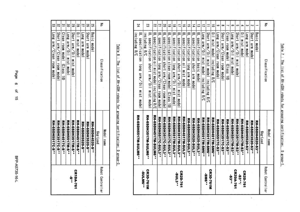
253
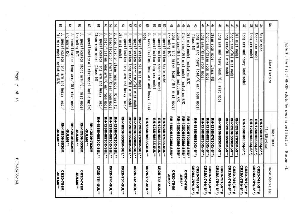
254
255
256
257
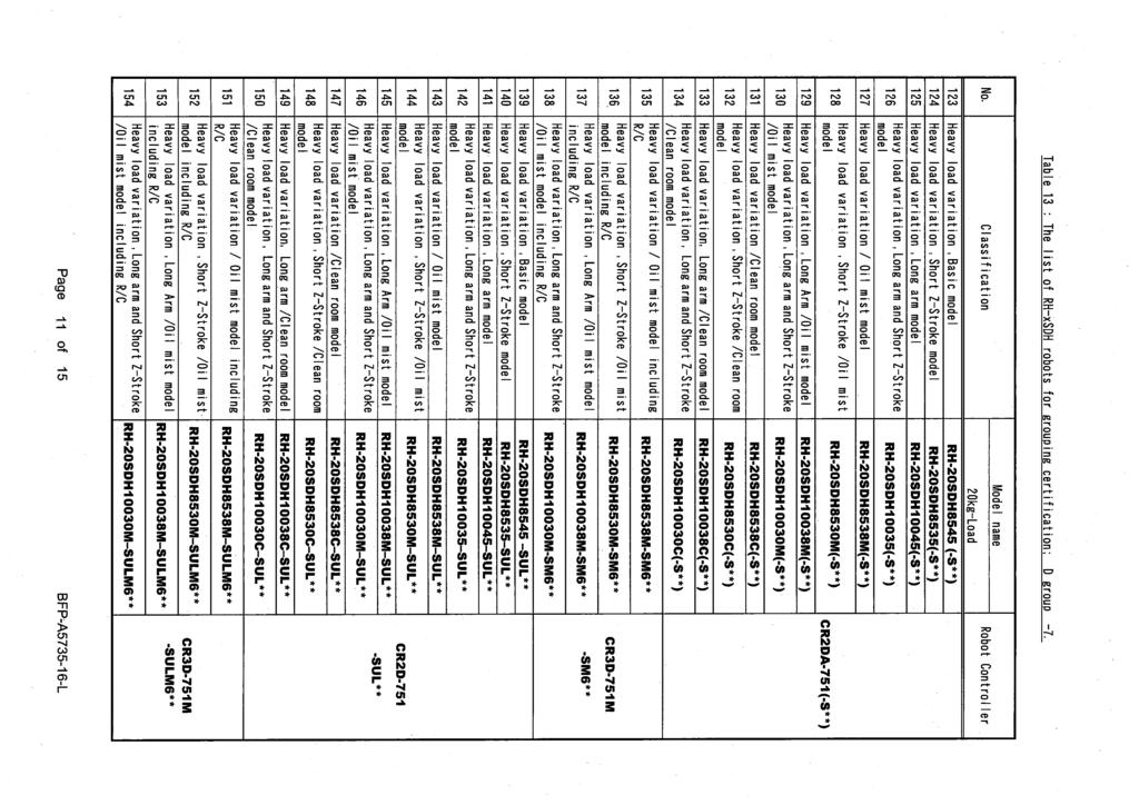
258
259
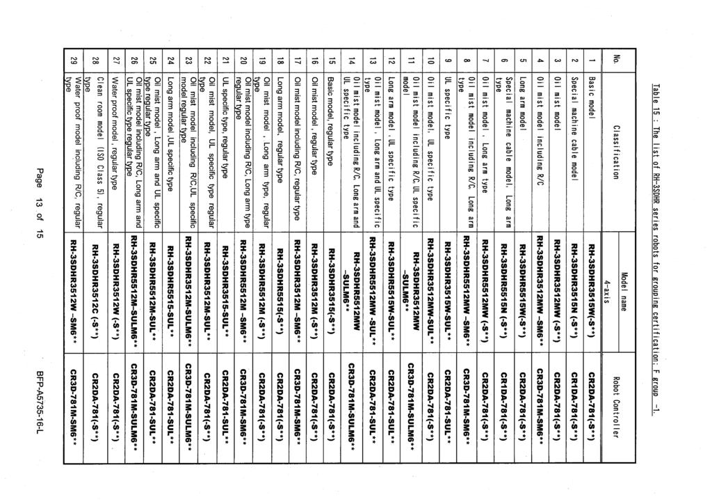
260
RH-6FH-D/12FH-D/20FH-D Series RH-3FHR-D Series Standard Specifications Manual
 Mitsubishi Industrial Robot CR750-D/CR751-D Controller RH-6FH-D/12FH-D/20FH-D Series RH-3FHR-D Series Standard Specifications Manual BFP-A8863-AJ Safety Precautions Always read the following precautions
RH-6FH-Q/12FH-Q/20FH-Q Series
 Mitsubishi Industrial Robot RH-6FH-Q/12FH-Q/20FH-Q Series Special Specifications Manual (CR750-Q Controller) BFP-A8882-K Safety Precautions Always read the following precautions and the separate "Safety
RH-FRH Series Standard Specifications Manual
 Mitsubishi Electric Industrial Robot CR800 Series Controller RH-FRH Series Standard Specifications Manual RH-3FRH series RH-6FRH series RH-12FRH series RH-20FRH series RH-3FRHR series BFP-A3468-D Safety
RV-4F-Q/7F-Q/13F-Q/20F-Q Series
 Mitsubishi Industrial Robot RV-4F-Q/7F-Q/13F-Q/20F-Q Series Standard Specifications Manual (CR750-Q Controller) BFP-A8933-G Safety Precautions Always read the following precautions and the separate "Safety
RV-4F-D/7F-D/13F-D/20F-D/35F-D/50F-D/ 70F-D Series Standard Specifications Manual
 Mitsubishi Industrial Robot CR750-D/CR751-D/CR760-D Controller RV-4F-D/7F-D/13F-D/20F-D/35F-D/50F-D/ 70F-D Series Standard Specifications Manual BFP-A8931-AB Safety Precautions Always read the following
Mitsubishi Industrial Robot. RH-3FH-D Series. Special Specifications Manual. (CR750-D/CR751-D Controller) BFP-A8878-J
 BFP-A8878-J") Mitsubishi Industrial Robot RH-3FH-D Series Special Specifications Manual (CR750-D/CR751-D Controller) BFP-A8878-J Safety Precautions Always read the following precautions and the separate "Safety Manual"
Mitsubishi Industrial Robot RH-3FH-D Series Special Specifications Manual (CR750-D/CR751-D Controller) BFP-A8878-J Safety Precautions Always read the following precautions and the separate "Safety Manual"
MITSUBISHI ELECTRIC CORPORATION
 MITSUBISHI Changes for the Better Mitsubishi Electric Corporation Industrial MELFA Technical News Robot BFPA60790215E* January 2018 Subject: Precautions of replacement from RH6SDH to RH6FRHD Applicable
RV-SD series. RV-6SD/6SDL Series MITSUBISHI INDUSTRIAL ROBOT RV-6SD RV-6SDL
 MITSUBISHI INDUSTRIAL ROBOT RV-6SD/6SDL Series RV-6SD RV-6SDL RV-SD series The Ultimate Series of Powerful Mitsubishi Robots A new high performance controller design offers faster speed and greater accuracy.
RV-6SD/6SDL Series MITSUBISHI INDUSTRIAL ROBOT RV-6SD RV-6SDL. RV-SD series
 MITSUBISHI INDUSTRIAL ROBOT /6SDL Series RV-SD series The Ultimate Series of Powerful Mitsubishi Robots A new high performance controller design offers faster speed and greater accuracy. Enhanced compatibility
RV-4F-Q/7F-Q/13F-Q/20F-Q/35F-Q/50F-Q/ 70F-Q Series Standard Specifications Manual
 Mitsubishi Industrial Robot CR750-Q/CR751-Q/CR760-Q Controller RV-4F-Q/7F-Q/13F-Q/20F-Q/35F-Q/50F-Q/ 70F-Q Series Standard Specifications Manual BFP-A8933-Y Safety Precautions Always read the following
RV-FR Series Standard Specifications Manual
 Mitsubishi Electric Industrial Robot CR800 Series Controller RV-FR Series Standard Specifications Manual RV-2FR series RV-4FR series RV-7FR series RV-13FR series RV-20FR series BFP-A3470-B Safety Precautions
RV-FR Series Standard Specifications Manual
 Mitsubishi Electric Industrial Robot CR800 Series Controller RV-FR Series Standard Specifications Manual RV-2FR series RV-4FR series RV-7FR series RV-13FR series RV-20FR series BFP-A3470-D Safety Precautions
CR2/CR2A/CR2B Controller INSTRUCTION MANUAL
 MITSUBISHI Mitsubishi Industrial Robot CR2/CR2A/CR2B Controller INSTRUCTION MANUAL Controller setup, basic operation, and maintenance BFP-A5991-J Safety Precautions Always read the following precautions
MELFA Technical News. Mitsubishi Electric Corporation Industrial Robot. Changes for the Better
 Changes for the Better Mitsubishi Electric Corporation Industrial Robot MELFA Technical News BFPA60790211E* January 2018 Subject: Precautions of replacement from RV3SD/3SDJ to RV4FRD/4FRLD Applicable to:
MELFA RV-1A/RV-2AJ INDUSTRIAL ROBOTS
 INDUSTRIL ROBOTS MELF RV-1/ Combining Compact Design & Operational Ease. Mitsubishi Electric s newest all-purpose industrial robots designed for the industrial world. Mitsubishi Electric Industrial Robots
Standard specifications RS007LFF60
 Standard specifications RS007LFF60 December 05, 2017 KAWASAKI HEAVY INDUSTRIES, LTD. ROBOT DIVISION Materials and specifications are subject to change without notice. Specification : (Arm): (Controller):
MITSUBISHI Mitsubishi Industrial Robot
 MITSUBISHI Mitsubishi Industrial Robot CRn-500 series INSTRUCTION MANUAL ADDITIONAL AXIS INTERFACE BFP-A8107-D Supplemental Instruction About the power supply synchronization with the robot controller.
RH-1FHR-Q-S60 Series Special Specifications Manual
 Mitsubishi Industrial Robot CR750-Q/CR751-Q Controller RH-1FHR-Q-S60 Series Special Specifications Manual BFP-A3333 Safety Precautions Always read the following precautions and the separate "Safety Manual"
MELFA Technical News BFP-A E-A
 MITSUBISHI Changes for the Better Title Mitsubishi Electric Applicable models Industrial Precautions for Replacing RH20SDH/20SQH with RH20FHD/Q RH20SDH,RH20SQH RH20FHD, RH20FHQ Robots MELFA Technical News
Mitsubishi Industrial Robot. RV-6S Series. Standard Specifications Manual. (CR3-535M/CR2B-574 Controller) BFP-A8322-E
 BFP-A8322-E") Mitsubishi Industrial Robot RV-6S Series Standard Specifications Manual (CR3-535M/CR2B-574 Controller) BFP-A8322-E Supplemental Instruction Thank you for purchasing the Mitsubishi Industrial Robot MELFA
Mitsubishi Industrial Robot RV-6S Series Standard Specifications Manual (CR3-535M/CR2B-574 Controller) BFP-A8322-E Supplemental Instruction Thank you for purchasing the Mitsubishi Industrial Robot MELFA
Standard specifications BA006LFE01C01
 Standard specifications BA006LF01C01 ###### 1st dition : August 30, 2016 KAWASAKI HAVY INDUSTRIS, LTD. ROBOT DIVISION Materials and specifications are subject to change without notice. Specification :
Mitsubishi Industrial Robot. RV-3S/3SJ Series. Standard Specifications Manual. (CR1B-571 Controller) BFP-A8387-D
 BFP-A8387-D") Mitsubishi Industrial Robot RV-3S/3SJ Series Standard Specifications Manual (CR1B-571 Controller) BFP-A8387-D Supplemental Instruction Thank you for purchasing the Mitsubishi Industrial Robot MELFA Series.
Mitsubishi Industrial Robot RV-3S/3SJ Series Standard Specifications Manual (CR1B-571 Controller) BFP-A8387-D Supplemental Instruction Thank you for purchasing the Mitsubishi Industrial Robot MELFA Series.
Standard specifications MC20-01-AX20 MC10L-01-AX20
 Standard specifications MC20-01-AX20 MC10L-01-AX20 8th edition 0912, SMCEN-017-008,001 Table of contents 1. Outline...1 1.1. MC robot... 1 1.2. AX20 controller...1 2. Characteristic...2 2.1. MC robot...
Mitsubishi Industrial Robot CR750/CR751/CR760 Series Controller INSTRUCTION MANUAL
 Mitsubishi Industrial Robot CR750/CR751/CR760 Series Controller INSTRUCTION MANUAL Troubleshooting This instruction manual apply to both the CR-750-Q/CR751-Q/CR760-Q controller corresponding to iq Platform,
RV-2F-Q Series Standard Specifications Manual
 Mitsubishi Industrial Robot CR750-Q/CR751-Q Controller RV-2F-Q Series Standard Specifications Manual BFP-A8902-AA Safety Precautions Always read the following precautions and the separate "Safety Manual"
Standard specifications ST AX ST70L-01-AX
 Standard specifications ST100-01-AX ST70L-01-AX 1st edition: Feb 2008 NACHI-FUJIKOSHI CORP. Robot Production Plant Table of contents 1. Outline...1 1.1. Robot...1 1.2. AX controller...1 2. Characteristic...2
Standard specifications MR20-02-AX20 MR20L-01-AX20
 Standard specifications MR20-02-AX20 MR20L-01-AX20 6th edition 0912, SMREN-017-006,001 Table of contents 1. Outline...1 1.1. MR robot... 1 1.2. AX20 controller...1 2. Characteristic...2 2.1. MR robot...
Robot Control. Robotics. Robot Control. Vladimír Smutný
 Robot Control Robotics Robot Control Vladimír Smutný Center for Machine Perception Czech Institute for Informatics, Robotics, and Cybernetics (CIIRC) Czech Technical University in Prague Kinematic Model
Robot Control. Robotics. Robot Control. Vladimír Smutný. Center for Machine Perception
 Robot Control Robotics Robot Control Vladimír Smutný Center for Machine Perception Czech Institute for Informatics, Robotics, and Cybernetics (CIIRC) Czech Technical University in Prague ROBOTICS: Vladimír
EUROPE R-SERIES. up to 80 kg payload
 EUROPE R-SERIES up to 80 kg payload »Simple and friendly«into THE FUTURE»40 years of experience and state-of-the-art robot technology«the R-SERIES 1. High speed 4. Protection Kawasaki Robotics invents
MELFA RV-6S/6SL Series RV-12S/12SL Series Palletizing precision is improved. Trajectory precision is improved.
 Mitsubishi Electric Industrial s -Highly Capable s MELF RV-/L Series and RV-/L Series [1] Optimal cceleration/deceleration Control / Optimal Override Function [2] Correction rograing this kind of application
Supporting Supplement Manual
 YAMAHA ROBOT CONTROLLER Supporting Supplement Manual ENGLISH E E72-Ver. 1.03 MEMO INTRODUCTION Thank you for purchasing the YAMAHA ERCX/SRCX/DRCX series robot controller. This supplement manual describes
The Flexible Heavy-Duty Robot
 The Flexible Heavy-Duty Robot up to kg payload Kawasaki Robotics (USA), Inc. THE FLEXIBLE HEAVY-DUTY ROBOT The high payload long reach Z-Series robots were developed using Kawasaki s advanced technology
H Series PLC. ! : Indicates Compulsion. EH-150 Analog input module EH-AXH8M Instruction manual. Safety precautions DANGER CAUTION COMPULSION
 H Series PLC EH-150 Analog input module EH-AXH8M Instruction manual Thank you for purchasing a Hitachi Programmable Logic Controller. To operate it safely, please read this instruction manual and all the
HITACHI. EH-150 series PLC EH-RTD8 Resistance Temperature Detective input module Instruction manual. Safety precautions
 HITACHI EH-150 series PLC Resistance Temperature Detective input module Instruction manual Thank you for purchasing a Hitachi Programmable Logic Controller. To operate it safely, please read this instruction
EQUIPMENT OPERATION MANUAL
 EQUIPMENT OPERATION MANUAL Loctite 200, 300, and 400 Series Benchtop Robots Book 1 of 4: A Company FOR SAFE USE Safety Notes Read the following Warnings and Cautions thoroughly for the safe use of the
MITSUBISHI. Mitsubishi Industrial Robot. Explanations of MOVEMASTER COMMANDS BFP-A8056-E
 MITSUBISHI Mitsubishi Industrial Robot CR1/CR2 Controller INSTRUCTION MANUAL Explanations of MOVEMASTER COMMANDS BFP-A8056-E Safety Precautions Always read the following precautions and the separate "Safety
High-Speed, High-Performance Industrial Robots
 High-Speed, High-erformance Industrial Robots up to 80 kg payload Kawasaki Robotics (USA), Inc. HIGH-SEED, HIGH-ERFORMANCE INDUSTRIAL ROBOTS The new R-Series Robots are setting the benchmark for all small
Motorized Linear Slides. EZS2 Series
 Motorized Linear Slides EZS Series Advancing Positioning Applications Oriental Motor's Motorized Linear Slides The EZS Series motorized linear slide is designed to achieve greater convenience and performance
RP-1AH/3AH/5AH Series
 MITSUBISHI Mitsubishi Industrial Robot RP-1AH/3AH/5AH Series Standard Specifications Manual (CR1-571 Controller) BFP-A8104-H Supplemental Instruction This document additionally explains the specification
MDM 011-Z1 Regen Resistor
 MDM 011-Z1 Regen Resistor Date of creation: 10.04.2017 Version date: 10.04.2017 Article number: 09-402-011-Z1-E Publisher: SIGMATEK GmbH & Co KG A-5112 Lamprechtshausen Tel.: 06274/4321 Fax: 06274/4321-18
INVERTER A800 PLC Function Quick Start Guide
 INVERTER A800 PLC Function Quick Start Guide FR Configurator2 Compatible For Beginners Sequence Control READ BEFORE USING Before using this product, read this Quick Start Guide and the related manuals
Mitsubishi Industrial Robot
 Mitsubishi Industrial Robot CR750/CRn-700 Series R56TB/R57TB Instruction Manual BFP-A8684-F Safety Precautions Always read the following precautions and the separate "Safety Manual" before starting use
Horizontal Articulaed Robot IXP Series PowerCon SCARA. Instruction Manual First Edition
 Horizontal Articulaed Robot IXP Series PowerCon SCARA Cleanroom Type, Arm Length 350/450/550/650 IXP-3C3515, IXP-4C3515 IXP-3C4515, IXP-4C4515 IXP-3C5520, IXP-4C5520 IXP-3C6520, IXP-4C6520 Dust Proof/Splash
PSU. User s manual. Rev. 0
 PSU User s manual Rev. 0 2010 1 This user manual is for the standard version of the converter. All information in this user manual, including methods, techniques and concepts described herein, are proprietary
Installation and Connection Manual
 F Series Installation and Connection Manual Kawasaki Heavy Industries, Ltd. 90202-1183DEB Preface Preface This manual describes the installation and connection of the controller. This manual covers the
Installation and Connection Manual
 E Series Installation and Connection Manual Kawasaki Heavy Industries, Ltd. 90202-1110DEN PREFACE This manual describes the installation and connection of the E series controllers. This manual covers the
EUROPE Y-SERIES. up to 3 kg payload
 EUROPE Y-SERIES up to 3 kg payload »Simple and friendly«into THE FUTURE»40 years of experience and state-of-the-art robot technology«the Y-SERIES 1. Speed 4. Flexibility Fast Pick & Place Operations are
EQUIPMENT OPERATION MANUAL
 EQUIPMENT OPERATION MANUAL Loctite S440 Series SCARA Robots Book 2 of 4: Quick Start A Company FOR SAFE USE Safety Notes Read the following Warnings and Cautions thoroughly for the safe use of the Scara
TTA Series. Tabletop Robot. ZR-Axis Type Series Added
 GB Tabletop Robot TTA Series ZR-Axis Series Added www.intelligentactuator.de mproved Tabletop Robot for Cell Production Applications. Featuring Significantly Higher Payload, Maximum Speed and Rigidity!
Zenith DS9000 Dispensing System
 Page Date: 04/2009 Zenith DS9000 Dispensing System Installation & Operation Manual Page 2 Table of Content Introduction... 3 Control Specification... 4 Wiring Diagram... 5 Wiring Instructions... 6 Field
Series IZH10. Handheld Electrostatic Meter. How to Order. Accessories and Option / Part Number for Individual Parts.
 Peak G 15min Handheld Electrostatic Meter Series IZH10 How to Order IZH10 Option Nil H None High-voltage measuring handle Accessories and Option / Part Number for Individual Parts The ground wire and soft
Removal and Installation8
 8 Screw Types 8-4 Top Cover Assembly 8-5 Left Hand Cover 8-6 Right Hand Cover 8-10 Front Panel Assembly 8-14 Left Rear Cover 8-15 Right Rear Cover 8-16 Extension Cover (60" Model only) 8-17 Media Lever
VECTOR INVERTER -INSTRUCTION MANUAL- HIGH RESOLUTION ANALOG INPUT / EXTRA CONTACT INPUT / THERMISTOR INTERFACE FR-V5AX
 VECTOR INVERTER -INSTRUCTION MANUAL- HIGH RESOLUTION ANALOG INPUT / EXTRA CONTACT INPUT / THERMISTOR INTERFACE FR-V5AX Thank you for choosing the Mitsubishi vector inverter option unit. This instruction
Installing Your 1394 Drive Interface Module
 Installation Instructions Installing Your Drive Interface Module (Catalog Number -DIM) Introduction This publication provides installation instructions for adding the Drive Interface Module to your system.
MITSUBISHI. Mitsubishi Industrial Robot. RV-2A/RV-3AJ Series. Standard Specifications Manual. (CR1-571 Controller) BFP-A8182-C
 BFP-A8182-C") MITSUBISHI Mitsubishi Industrial Robot RV-2A/RV-3AJ Series Standard Specifications Manual (CR1-571 Controller) BFP-A8182-C Safety Precautions Always read the following precautions and the separate "Safety
MITSUBISHI Mitsubishi Industrial Robot RV-2A/RV-3AJ Series Standard Specifications Manual (CR1-571 Controller) BFP-A8182-C Safety Precautions Always read the following precautions and the separate "Safety
MRZJW3- SETUP154E. General-Purpose AC Servo Servo Configuration Software MODEL INSTALLATION GUIDE
 General-Purpose AC Servo Servo Configuration Software MODEL MRZJW3- SETUP154E INSTALLATION GUIDE Thank you for choosing the Mitsubishi general-purpose AC servo Servo Configuration Software. To optimize
Remote I/O Unit with Connectors for Light Curtain CC-Link Safety System. panasonic.net/id/pidsx/global
 715 LIGHT CURTAINS / USE Remote I/O Unit with Connectors for Light Curtain CC-Link System General terms and conditions... F-7 Related Information... P.703~ SF4B... P.565~ General precautions... P.1501
Absolute Rotary Encoder E6C-N. Ordering Information. Ideal for Stepping Motor Tripping Detection and Position Control of Loaders or Unloaders
 Absolute Rotary Encoder Ideal for Stepping Motor Tripping Detection and Position Control of Loaders or Unloaders No need to reset origin point at power-up IP50 certification Ideal for packaging, plastics,
PanelView Plus/VersaView CE Terminals and Display Modules
 Installation Instructions PanelView Plus/VersaView CE Terminals and Display Modules (Catalog Numbers 2711P-xxxxxx, 6182H-xxxxxx) English Inside: Overview...2 For More Information...2 Modular Components...3
Mitsubishi Electric Automation Instruction Manual FR-A5AC-01
 Mitsubishi Electric Automation Instruction Manual FR-A5AC-01 AC Input Interface Option Unit NOTE: CAUTION: WARNING: NOTES, CAUTIONS AND WARNINGS Notes are used to provide additional detail about a procedure.
Mechanical, analog system comprising sensor and processor for accurately recording the position of gripper jaws.
 APS-M1 Accessories Sensor System Analog Position Sensor Analog Position Sensor System Mechanical, analog system comprising sensor and processor for accurately recording the position of gripper jaws. Function
Controller RP-1AH/3AH/5AH
 MITSUBISHI ELECTRIC MELFA Industrial Robots Specifications Manual Controller RP-1AH/3AH/5AH Art. no.: 133797 05 07 2002 BFP-A8104-D MITSUBISHI ELECTRIC INDUSTRIAL AUTOMATION Safety Precautions Always read
DX200 OPTIONS MECHATROLINK-II COMMUNICATION FUNCTION INSTRUCTIONS
 DX200 OPTIONS MECHATROLINK-II COMMUNICATION FUNCTION INSTRUCTIONS (FOR MP2110-ET3 MADE BY YASKAWA ELECTRIC CORPORATION ) Upon receipt of the product and prior to initial operation, read these instructions
F1000 User's Manual. (Version: V1.01)
") (Version: V1.01) Contents Chapter 1 Overview... 2 Chapter 2 Installation... 3 2.1 Installation guide... 3 2.1.1 Installation position... 3 2.1.2 NEMA4 standard installation... 3 2.1.3 Environment precautions...
(Version: V1.01) Contents Chapter 1 Overview... 2 Chapter 2 Installation... 3 2.1 Installation guide... 3 2.1.1 Installation position... 3 2.1.2 NEMA4 standard installation... 3 2.1.3 Environment precautions...
TXM1.8RB. TX-I/O Blinds module
 s 8 178 8178p01 TX-I/O Blinds module TXM1.8RB 8 non-floating relay outputs for... 4 blinds motors with 2 end switches, or 2 blinds motors with 3 end switches, or 2 blinds motors with 2 end switches + 1
IV-30 Operating Manual for Pulse Distributor Cassette with potential separation
 IV-30 Operating Manual for Pulse Distributor Cassette with potential separation Edition-/Rev.-Date: 09/08/2006 Document-/Rev.-No.: TR - EAK - BA - GB - 0093-02 Software version: - File name: TR-EAK-BA-GB-0093-02.DOC
P3-RS Remote Slave Module
 P3-RS Rack with CPU Module Racks with P3-RS Modules The P3-RS is a full-featured, highperformance, Remote Slave module. Features include a line x 0 charactor LCD display and five communications ports
KR QUANTEC K ultra. Robots. With F Variants Specification. KUKA Roboter GmbH. Issued: Version: Spez KR QUANTEC K ultra V10 KR QUANTEC
 Robots KUKA Roboter GmbH KR QUANTEC K ultra With F Variants Specification KR QUANTEC K ultra Issued: 02.09.2016 Version: Spez KR QUANTEC K ultra V10 Copyright 2016 KUKA Roboter GmbH Zugspitzstraße 140
JANOME DESKTOP ROBOT JR2000N Series. Operation Manual. <Setup> For Qualified Installer ONLY
 JANOME DESKTOP ROBOT JR2000N Series Operation Manual For Qualified Installer ONLY Thank you for purchasing the Janome Robot. *Read this manual thoroughly in order to properly use this robot. Be sure
INSTALLATION INSTRUCTIONS
 INSTALLATION INSTRUCTIONS Adaptor Model No. CZ-CFUNC1U For your safety Read the following instructions carefully, and carry out secure installation and electrical work. The precautions given in this manual
DC I/O Conversion Module FA-TB32XY
 DC I/O Conversion Module FA-TB32XY User's Manual Thank you for purchasing FA Goods product. Before using, please read this User s Manual and the relevant manuals carefully to ensure correct use. SAFETY
When any of the following symbols appear, read the associated information carefully. Symbol Meaning Description
 Uni-I/O Modules Installation Guide UID-0808THS Uni-I/O is a family of Input/Output modules that are compatible with the UniStream control platform. This guide provides basic installation information for
Description: IRB-540 Robot with 6-axis Flexi-Wrist Manipulator, S4P Controller, Conveyor Tracking, and Analog Paint Regulation (APR)
") Standard Module # Description: IRB-540 Robot with 6-axis Flexi-Wrist Manipulator, S4P Controller, Conveyor Tracking, and Analog Paint Regulation (APR) The IRB-540 Flexi-Wrist finishing robot is specifically
Standard Module # Description: IRB-540 Robot with 6-axis Flexi-Wrist Manipulator, S4P Controller, Conveyor Tracking, and Analog Paint Regulation (APR) The IRB-540 Flexi-Wrist finishing robot is specifically
panasonic.net/id/pidsx/global CCD The sensor can be used for various applications with its binary data output with four different sensing modes.
 1123 PHOTO PHOTO PARTICUR Type Edge Sensor SERIES Related Information General terms and conditions... F-3 About laser beam... P.1593~ guide... P.1021~ General precautions... P.1595 Conforming to FDA regulations
Robots. KUKA Roboter GmbH KR 360 FORTEC. With F and C Variants Specification. Issued: Version: Spez KR 360 FORTEC V2
 Robots KUKA Roboter GmbH KR 360 FORTEC With F and C Variants Specification Issued: 16.04.2014 Version: Spez KR 360 FORTEC V2 Copyright 2014 KUKA Laboratories GmbH Zugspitzstraße 140 D-86165 Augsburg Germany
Observe organization standards and regulations, etc., related to the safety of the device design. Do not remove devices before confirming safety.
 Safety Precautions Always read this section before use. When designing equipment using, the manufacturer is obligated to ensure that the safety of the mechanism and the system that runs by the electrical
LED PANEL. User Manual Please read the instructions carefully before use LED-7TC. Innovation, Quality, Performance 15-
 LED PANEL LED-7TC Innovation, Quality, Performance User Manual Please read the instructions carefully before use 15- 9. Fixture Cleaning TABLE OF CONTENTS 1. Safety Instructions 2. Technical Specifications
NIR Moisture Analyzer KB-30
 NIR Moisture Analyzer KB-30 Operation Manual Safety Precautions FPL950701 Improper use of the NIR moisture analyzer in violation of the following safety notes may result in death, injury or damage to property
PSU User s manual Rev. 0 January
 PSU User s manual Rev. 0 January 2011 1 This user manual is for the standard version of the converter. All information in this user manual, including methods, techniques and concepts described herein,
Installation Guide. QBox-V6. Standalone/Spare V6 SDI QBox. Standalone/Spare V6 SDI QBox. Part No. A
 Installation Guide Standalone/Spare V6 SDI QBox QBox-V6 Standalone/Spare V6 SDI QBox Part No. A9009-0004 EN www.autocue.com Copyright 2017 All rights reserved. Original Instructions: English All rights
Teach Pendant. Applications. Used on all Nachi robot products. Open Concept
 AW AW Nachi Industrial Robot Controller This high-performance, multi-tasking controller offers an open concept design, along with increased performance and improved menudriven programming. Reliability
Line reactors SINAMICS. SINAMICS G130 Line reactors. Safety information 1. General. Mechanical installation 3. Electrical installation
 Safety information 1 General 2 SINAMICS SINAMICS G130 Mechanical installation 3 Electrical installation 4 Technical specifications 5 Operating Instructions Control version V4.7 04/2014 A5E00331462A Legal
Product Information. ECN 1023 EQN 1035 Rotary Encoders with EnDat 2.2 for Safety-Related Applications
 Product Information ECN 1023 EQN 1035 Rotary Encoders with EnDat 2.2 for Safety-Related Applications January 2009 ECN 1023/EQN 1035 Series Rotary encoders for safety-related applications With integral
LED PANEL. User Manual Please read the instructions carefully before use LED-212RGB TABLE OF CONTENTS. 1. Safety Instructions
 TABLE OF CONTENTS LED PANEL 1. Safety Instructions 2. Technical Specifications 3. Installation 4. How to set the unit 5. How to control the fixture 6. DMX512 Configuration 7. DMX512 Connections 8. Troubleshooting
DSTHM-2 COMBINED T AND RH DUCT TRANSMITTER. Mounting and operating instructions
 Mounting and operating instructions Table of contents SAFETY AND PRECAUTIONS 3 PRODUCT DESCRIPTION 4 ARTICLE CODES 4 INTENDED AREA OF USE 4 TECHNICAL DATA 4 STANDARDS 4 OPERATIONAL DIAGRAMS 5 WIRING AND
G9SX-GS. Safety Guard Switching Unit. A Safety Measure for Hazardous Operations That Does Not Lower Productivity. Auto Switching Function
 Safety Guard Switching Unit CSM DS_E_6_1 A Safety Measure for Hazardous Operations That Does Not Lower Productivity Two functions support two types of application: Auto switching: For applications where
TECHNICAL MANUAL Simplified Operation Panel
 INDUSTRIAL SEWING MACHINE MODEL PLK-G10 TECHNICAL MANUAL Simplified Operation Panel A180E670P01 ... Contents... 1. For safe use 1 2. Precautions for use 3 3. Initial settings (Language / Model settings)
Operating instructions. Speed monitor D / / 2014
 Operating instructions Speed monitor D200 80005257 / 00 05 / 2014 Contents 1 Preliminary note...4 1.1 Symbols used...4 1.2 Warning signs used...4 2 Safety instructions...5 2.1 General...5 2.2 Target group...5
Package Contents. GP Options (Made by Digital)
") When connecting the power cord terminals to the GP, be sure the cord has first been unplugged from the power outlet to prevent the possibility of an electric shock. With the exception of changing the GP's
When connecting the power cord terminals to the GP, be sure the cord has first been unplugged from the power outlet to prevent the possibility of an electric shock. With the exception of changing the GP's
RTT2 ROOM TEMPERATURE SWITCH. Mounting and operating instructions
 Mounting and operating instructions Table of contents SAFETY AND PRECAUTIONS PRODUCT DESCRIPTION ARTICLE CODES INTENDED AREA OF USE TECHNICAL DATA STANDARDS OPERATIONAL DIAGRAMS WIRING AND CONNECTIONS
Operation Manual WARNING. Be sure to read this Operation Manual before use. Universal Space Amusement Equipment Ltd.
 WARNING Be sure to read this Operation Manual before use. Universal Space Amusement Equipment Ltd. CONTENTS 1. The company..2 2. Specifications.. 3 3. Package Contents..5 4. Installation, Fix and Transport..6
EC07 EC63. Compatible actuators: ERL2 ESD2. How to order EC 07 B. Series. B Installation. method
 Controller EC07 EC63 Compatible actuators: ERL ESD Features Compact, light weight and thin (Body width 35mm) Can be set without manual Perfect installation compatibility with actuator PC software available
QUICK START GUIDE. vau4/3. Frequency converter. operating instructions /12
 operating instructions QUICK START GUIDE Frequency converter vau4/3 28100241101 12/12 1 Safety information Warning of electrical shock! Danger to life! Electrical shock can cause serious injury or even
OPERATING INSTRUCTIONS 7 SERIES STATIC GENERATORS
 OPERATING INSTRUCTIONS 7 SERIES STATIC GENERATORS GB Contents Page 1 Introduction 4 2 Safety 5 3 Use 6 4 Checking on Delivered Equipment 6 5 General Specification and Dimensions 7 6 Positioning 10 7 Operating
Manual Version: V1.00. Video Decoder Quick Guide
 Manual Version: V1.00 Video Decoder Quick Guide Thank you for purchasing our product. If there are any questions, or requests, please do not hesitate to contact the dealer. Copyright Copyright 2016 Zhejiang
HST -TZ1 Guard-locking mechanism (Translation of Original Manual)
") Installation and Operating Manual for Components HST -TZ1 Guard-locking mechanism (Translation of Original Manual) HST-TZ1 Ident.-No.: 10234 HST-TZ1 Ident.-No.: 10236 HST-TZ1 Ident.-No.: 10235 HST-TZ1
Installation and Operating Manual for Components HST -TZ1 Guard-locking mechanism (Translation of Original Manual) HST-TZ1 Ident.-No.: 10234 HST-TZ1 Ident.-No.: 10236 HST-TZ1 Ident.-No.: 10235 HST-TZ1
VS-P Series. TDK-Lambda INSTRUCTION MANUAL
 VS5P /75P /1P/ 15P Instruction Manual BEFORE USING THE POWER SUPPLY UNIT Pay attention to all warnings and cautions before using the unit. Incorrect usage could lead to an electrical shock, damage to the
Installation Guide Controller Series E130/E230/E430
 Controller Series E0/0/0 Installation Guide Controller Series E0/E0/E0 Products E0-DP E0-DP E0-DP Content IMPORTANT NOTES FOR E0/E0/E0 SERIES CONTROLLERS... SYSTEM OVERVIEW... E0 SERIES FUNCTION AND WIRING...
Product Information ROC 425 ROQ 437. Absolute Rotary Encoders with EnDat 2.2 for Safety-Related Applications
 Product Information ROC 425 ROQ 437 Absolute Rotary Encoders with EnDat 2.2 for Safety-Related Applications 10/2016 ROC 425, ROQ 437 with synchro flange Rotary encoders for absolute position values with