Copyright 2003 All rights reserved All trademarks in this manual are the property of their respective trademark owners.
|
|
|
- Franklin Golden
- 5 years ago
- Views:
Transcription
1
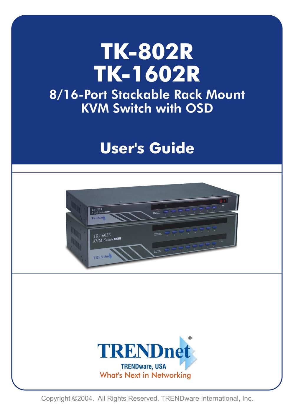
2 Copyright and trademarks Copyright 2003 All rights reserved All trademarks in this manual are the property of their respective trademark owners. Disclaimer This User Guide fully explains the installation and use of TK-802R/TK-1602R Rack Mount KVM Switch. Since every precaution has been taken to prepare and write this manual, we assumes no responsibility for errors or omissions contained therein, nor any liability for damages resulting from the use of the information in it. Specifications and functions may be changed without prior notice Icon convention used in this User Guide This brightened light bulb indicates some useful hints you should know before proceed with following instructions. This lightning bolt indicates warnings you should take special precautions against.
3 TABLE OF CONTENTS TABLE OF CONTENTS...3 LIST OF FIGURES...5 LIST OF TABLES FEATURES AND FUNCTIONS FEATURES...7 General features...7 Connector Interface...7 LED display for status monitoring...7 Control features...7 Security...7 Cascaded Application...7 Hardware/Software Support...8 Power interface...8 Cabling requirements PACKAGE CONTENTS EXTERNAL VIEWS Front View Front-panel Buttons Numerical LED Displays and Indicators Rear View Power Jack Console Port PC Port Daisy Chain Port KVM SWITCH TECHNOLOGY OVERVIEW INSTALLATION CHECKLIST BEFORE INSTALLATION MOUNTING THE KVM SWITCH CONNECT YOUR PCS AND PERIPHERALS TO SINGLE KVM SWITCH CONNECT YOUR PCS AND PERIPHERALS TO MULTIPLE DAISY-CHAINED KVM SWITCHES INITIALIZE YOUR KVM SWITCH Reset without disconnecting or powering down your computers OPERATION CONTROL INTERFACES Front-panel Buttons Keyboard Hotkeys On een Display OSD Navigation OSD Option Selection Edit the OSD Option Parameter OPERATE THE SWITCH...21 <Select PC>...21 <Next lower channel>...22 <Next Higher Channel>...22 Table of Contents
4 <Next Lower Bank> (when daisy-chained)...22 <Next Higher Bank> (when daisy-chained)...23 <Autoscan Beep Sound On/Off>...23 <Reflash EEPROM>...23 <Find PC by Name>...24 <Change PC Name>...25 <Reset KVM>...25 <Show OSD Menu>...25 <Autoscan>...25 <Autoscan Delay Time>...26 <OSD Remain Time>...26 <Password Configuration>...26 <Password Change>...27 APPENDIX A TECHNICAL SPECIFICATIONS...28 APPENDIX B SYSTEM & CABLE REQUIREMENTS...30 APPENDIX C TROUBLESHOOTING...31 Table of Contents
5 LIST OF FIGURES Figure 1-1a TK-802R...8 Figure 1-1b TK-1602R...8 Figure 1-2a TK-802R Front Panel...9 Figure 1-2b TK-1602R Front Panel...9 Figure 1-3a TK-802R Rear Panel...10 Figure 1-3b TK-1602R Rear Panel...10 Figure 2-1 The 3-1 combo KVM cable is highly recommended...12 Figure 2-2 Daisy-chaining multiple KVM switches in a cascaded application...14 Figure 3-1 OSD Main Menu...19 Figure 3-2 Find PC by name searching...24 Figure 3-3 Bank number, Port Number and PC Name as shown on the OSD...24 LIST OF TABLES Table 3-1 Summary for Hotkey Sequences...18 Table B-1 Necessary accessories for the KVM Switches...30 Table B-2 The Standard 3-in-1 Keyboard-Video-Mouse Combo Cable...30 List of Figures &Tables
6 1. FEATURES AND FUNCTIONS The TK-802R/TK-1602R KVM Switch is a 8-/16-port cascadable PS/2 type KVM Switch with OSD control. It enables the network administrator to access, control, boot and reboot multiple connected computers using only one keyboard, video and mouse. Remote computer/server management from one keyboard, mouse and video The TK-802R/TK-1602R KVM Switch is a quality product designed for secure remote computer/server management on a centralized single admin desk in corporate, factory as well as in campus computing environment. It features a console port to connect your shared keyboard, video and mouse, and 8/16 PC ports to connect to your computers/servers. You can simply place it on desktop or mount it on a standard 19 rack for more secured and centralized management. This KVM Switch features a metal enclosure for better shielding against electromagnetic interference commonly seen in lab or factory floor environment. Easy Operation by front-panel buttons, keyboard hotkeys and OSD Menu controls The KVM Switch can be easily operated using front-panel buttons, keyboard hotkeys, as well as OSD Menu control. These available control interfaces yield more convenient and more effective operation over your daily network managing routines and hence more productivity for network administrator. Flexible port capacity through multiple daisy-chained KVM switches In addition to the choice over the 8/16-port capacity of each individual unit, users can also take advantage of its cascadable function to daisy-chain up to 16 units of the KVM Switches together. For example, with 16 units of the TK-1602R KVM Switches cascaded together, the total port capacity could easily be scaled up to 256 computers. You can also vary port capacity by daisy-chaining multiple units in different combination according to your real needs. Saving Time, Space and Money with more productivity The KVM switches offer special advantages saving time, space and money plus a significant boost over productivity of the network administrative staff. With our KVM Switches, you eliminate the need for a separate set of peripherals for each of your computers. With the number of servers running higher than ever in the corporate milieu, this will amount to a huge saving on money. The KVM users will also appreciate the neat space on desktop or working bench that is free from multiple keyboards, videos and mice. On the other hand, the net admin can save lots of time not to shift around separate sets of keyboard and mouse, just to keep up with the network management routines. Hence, the KVM Switch could be a tremendous help in facilitating a better and more efficient work environment for network administration, and an indispensable productivity tool that will definitely favored by the tech-savvy people. Page 6 Chapter 1 Features and Functions
7 1.1. Features General features 8-/16-port cascadable PS/2 type electronic KVM switch with OSD Menu control Robust metal case design ensures best EMI shielding and super video quality Standard 19 rack mount size Cost-effective remote workstation/server management solution for corporate, factory and campus computing environment Very high video resolution up to with superb video transfer quality and low distortion Buzzer sound for switching port confirmation while autoscanning User-specified parameters are saved within EEPROM memory, hence no need for reconfiguration after switch system reboot. Connector Interface PS/2 Keyboard and mouse connector interface 15-pin HDB video connector interface LED display for status monitoring Dual 7-segment LED displays for switch bank number Front-panel port status LEDs for easy and instant port status monitoring Control features Control multiple PCs from a single keyboard, monitor and mouse Front-panel buttons for direct channel selection Reset and Autoscan activated by front-panel key press and keyboard hotkey Keyboard hotkeys for quick operation commands OSD Menu options for more convenient and intuitive menu-driven control Channel selection by front-panel buttons, keyboard hotkeys and OSD Menu control Search the presence of a connected PC by its name Security Password security prevents unauthorized intrusion. Provide 8-character password protection. Cascaded Application Auto-detect daisy-chain configuration without setting any dipswitch Cascadable up to 16 units in daisy-chained configuration Port capacity easily scalable up to a maximum of 256 PCs using flexible combination of different switch units Dual 7-segment LED displays to indicate the switch bank number. Page 7 Chapter 1 Features and Functions


8 Hardware/Software Support Support a wide range of hardware in addition to the standard keyboard, video and mouse Support Microsoft IntelliMouse, IntelliMouse Explorer, Logitech NetMouse and other common wheel mouse Support a wide range of software platforms: DOS, Windows 3.x, Windows 95/98/SE/2000/ME/XP, Windows NT, Netware, OS2, Unix, Linux and BSD Hot-plugging of PCs for maintenance without powering down the KVM Switch or PC. Power interface Powered by the external power adapter connected to the AC power outlet in addition to the PS/2 keyboard/mouse interface power Cabling requirements Compatible with standard individual keyboard, video, and mouse cable Highly recommended: the 3-in-1 combination KVM cable 1.2. Package Contents The TK-802R/TK-1602R KVM Switch Package should contain the following items: The TK-802R/TK-1602R KVM Switch Daisy Chain Cable (3-in-1 KVM combo cable) Power adapter cord (AC to DC) Rack Mount Kit This User Guide A Quick Installation Guide / Quick Reference Sheet Figure 1-1a TK-802R Figure 1-1b TK-1602R Page 8 Chapter 1 Features and Functions


9 1.3. External Views The following sections will give detailed descriptions of the front-panel and rear panel of the TK-802R/TK-1602R KVM Switch Front View Figure 1-2a TK-802R Front Panel Figure 1-2b TK-1602R Front Panel Front-panel Buttons Use these front-panel buttons to directly select channels as well as to perform specific function such as reset or autoscan Numerical LED Displays and Indicators The Numerical LED display(s) and LED indicators on the front-panel show forth the information of your current switch bank number and port status. The current active switch bank will be shown on the Dual Numerical LED Displays while the Port Status is each indicated by a set of two Port Status LED indicators - one red and the other green. The red LED is lit when the computer is connected to the KVM Switch and feeding power through the PS/2 keyboard and mouse interface. The green LED is lit when the computer is currently selected as the active channel to be controlled with the shared keyboard and mouse. Note that a red-lit LED means only that the specific port is connected and being powered through its PS/2 interface. It does not indicate whether that connected computer is in powered-on or powered-off sate. Note that a green-lit LED means only that the specific port is selected to be the active channel. It does not indicate whether that connected computer is in powered-on or powered-off sate. Page 9 Chapter 1 Features and Functions
, the green LED of the active channel will be flashing to indicate this locked state.")

10 Thus the red indicator shows forth the current connected state of the specific port. The green LED indicator indicates the currently active channel. When the switch is in a locked mode (also known as password protected mode ), the green LED of the active channel will be flashing to indicate this locked state. Also all front-panel button operations will be disabled while in locked state Rear View Figure 1-3a TK-802R Rear Panel Figure 1-3b TK-1602R Rear Panel Power Jack The power jack is a receptacle for the 9V 1A DC power adapter cord. Its center pin is of a positive polarity Console Port The console port is where you connect your keyboard, video and mouse. Page 10 Chapter 1 Features and Functions
11 PC Port The PC port is where you connect your keyboard, video and mouse cable (or a 3-in- 1 combination cable) Daisy Chain Port The daisy-chain port is where you can daisy-chain to another switch for cascaded application of multiple KVM Switch units KVM Switch Technology Overview The KVM Switch is a hardware-based device that allows you to control multiple computers/servers using only one Keyboard, Video and Mouse, hence the name of the KVM Switch. The distinction between a KVM switch solution and any other software/hardware measures for the same control purpose is that: the KVM Switch exerts its control and operation on the connected computers only by the shared keyboard, video and mouse. It is more efficient and more versatile as being capable of control from BIOS level up to the GUI applications. Not only can a KVM switch save you money by eliminating the needs for multiple sets of keyboard, video and mouse, but also save you space from desktop, factory floor or office, and finally it saves you precious time that used to be spent in moving around different desktops, server rooms or even buildings. And the result is huge savings on many aspects plus a productivity boost. Since KVM Switch is a hardware device, it offers a transparency of control that will not interfere with the way a computer can be operated by and interacts with its user. As compared to other hardware/software solution for remote control, it takes an intrusive agent that will interfere with certain aspect of the computer or, at best, functions as well but eat up a considerable system resources or even large share of computing power, not to mention the extra costs which can be really expensive sometimes as the Enterprise Management Software. Therefore, the KVM Switch solution is better in this transparent sense for server/computer remote control. On the other hand, a KVM Switch also offers a complete and more flexile control than other software/hardware solutions: a KVM Switch offers a total control from BIOS level such as CMOS setting up to GUI application as well as and other maintenance routines. So obvious is the advantage of using KVM switch in an environment that requires users to control more than one computer. We can see the KVM Switch being deployed in many diverse applications and locations, whether it is SOHO, corporate or factory environment. And the professionals who use and come to appreciate the convenience and elegance of the KVM Switch range from SOHO workers, graphic artists, and network administrators to lab workers, floor supervisors and lab testing personnel, etc. Page 11 Chapter 1 Features and Functions

12 2. INSTALLATION Before installing the KVM switch, you should run through the following peripheral checklist to ensure a proper setup of your KVM Switch Checklist before Installation Suitable cables to connect the KVM Switch to the keyboard, video and mouse ports of each of your PC. For each computer connected, you should have PS/2 mouse cable (all male) and PS/2 keyboard cable (all male) and a HDB-15 VGA cable (all male). A 3-in-1 combo cable is highly recommended for your convenience. For more information on the cable specifications, look up in the Appendix A. A monitor with a standard D-sub 15-pin VGA/SVGA connector (HDB-15) that will work when connected directly to each of your PCs. A standard PS/2 style keyboard. If you are using an AT keyboard with a 5 pin connector you should use a standard AT-to-PS/2 keyboard adapter to connect to the KVM Switch. A PS/2 style Microsoft or Logitech compatible mouse or a Microsoft IntelliMouse / IntelliMouse Explorer compatible mouse Figure 2-1 The 3-1 combo KVM cable is highly recommended Page 12 Chapter 2 Installation
13 2.2. Mounting the KVM Switch The KVM Switch can be mounted either on desktop or on a standard 19 rack. To adapt to different port capacity requirements, you are able to use the KVM Switch either in single unit configuration or in multiple cascaded application. If you intend to use multiple cascaded KVM Switches, please jump to the next section Connect Your PCs and Peripherals to Single KVM Switch Before connecting any PC or peripherals to your KVM Switch, make sure that the power adapter is disconnected from your KVM Switch and all PC or peripherals that are going to be attached to the KVM Switch should be turned off. If you did not turn off your PCs while connecting to the KVM Switch, the shared keyboard and mouse will not be recognized. Step 1. Make sure your KVM Switch, your PCs and peripherals are all powered off. If not, turn the power off for the KVM switch, PCs and peripherals. Step 2. Connect the shared keyboard, PS/2 mouse and monitor to the console connectors on the rear of the KVM Switch. Step 3. Connect the power adapter cord to the KVM Switch to power it on. Step 4. Connect each computer system (still in powered-off state) to the KVM Switch in turn either with the individual keyboard cable, mouse cable and video cable, or the 3-in-1 keyboard/video/mouse combination cable for your convenience, then power on each computer The KVM Switch has to be turned on and properly connected to your PCs prior to your booting up any PC. Please follow the correct boot-up sequence. The reason is that: while your PC is booting up, it has to communicate with your keyboard and mouse and consequently gets response from them. If your KVM Switch has not been running and connected to your PC, your PC might have difficulty recognizing your keyboard and mouse, even if you turn on the KVM switch later on. On the other hand, your KVM Switch also has to be present to keep track of all the modes and parameters requested by the OS running on each connected PC. If your computers are with serial mouse connections and AT style keyboard connections, you should use the AT-to-PS/2 adapters specified in appendix C, Cable Diagrams. Note that even if you have an existing 6-pin mini-din to 9-pin serial adapter that came with your serial mouse, it might not work with your KVM Switch, since it might have a different wiring configuration. The cable distance from your keyboard, video and mouse to your PC should be within 25 feet (or 7.6 m) as to ensure signal quality and proper transmission. If you want to extend the distance over, use of a Cat5 Extender is recommended. Now the KVM Switch is ready to operate as soon as you turn on any of the attached computer. Page 13 Chapter 2 Installation
14 TK-802R_TK-1602R Rack Mount KVM Switch User s Guide July, Connect Your PCs and Peripherals to Multiple Daisy-chained KVM Switches If you use only a single KVM Switch and hence have no need for cascaded application of multiple KVM Switch units, just skip this section. To add port capacity, multiple TK-802R/TK-1602R KVM Switches can be cascaded in a daisy-chain configuration to maximize the number of connected computers up to a total of 256 computers (with 16 units of TK-1602R KVM Switches). This cascaded application is obviously advantageous when groups of computers are dispersed and with some considerable distance from each other. Each cascaded KVM can be away from the next KVM Switch up to 30 meters (dependent on your cable type), thus expanding the applicable distance of only one single KVM switch yet with the convenience of centralized control by one master KVM unit. Control commands can then be extended to groups of computers on the master KVM Switch on remote end through this daisy-chain connection. The KVM Switch units that are to be daisy-chained do not have to be of the same port capacity. In fact, you can daisy-chain different units with different port capacity as to scale the total port capacity more flexibly. Figure 2-2 Daisy-chaining multiple KVM switches in a cascaded application Page 14 Chapter 2 Installation
15 Before connecting any PC or peripherals to your KVM Switch, make sure that the power adapter is disconnected from your KVM Switch and all PC or peripherals to be attached to the KVM Switch should be turned off, too. If your PCs are not turned off while connecting to the KVM Switch, the shared keyboard and mouse won t be recognized correctly. Your multiple daisy-chained KVM Switches have to be set up and running before you can connect any PC or peripheral to any KVM Switch. Daisy-chain Multiple KVM Switches Step 1. Make sure your KVM Switch, your PCs and peripherals are all in poweredoff state. If not, turn the power off for the KVM switch, PCs and peripherals. Step 2. Connect the shared keyboard, PS/2 mouse and monitor to the console connectors on the rear of the master (first) KVM Switch. Step 3. Connect the power adapter cord to power on the master KVM Switch. Step 4. Use a daisy-chain cable to connect the daisy-chain port (labeled daisychain in) of the master switch to the console port of the second switch. Then connect the power chord to power on the second KVM switch. Step 5. If there is yet another third KVM Switch to be daisy-chained, just repeat step 4 to connect the daisy-chain port of the second switch to the console port of the third KVM switch. Likewise, follow the same connection principle if there is still more KVM Switch(es) to join in the daisy-chain. Step 6. After you have set up and powered up the daisy-chain connection of multiple KVM switches, you have to perform a first-time initialization for all the switches either by (1) pressing and holding down Button 1 on the master switch for at least 2 seconds, or (2) using the hotkey sequence: olllock + olllock + End for daisy-chain initialization. DO NOT PRESS Button 1 on any slave switch since this will initialize only the switches downstream from the slave switch on which you perform a reset. You can daisy-chain a total of up to 16 units of KVM Switches, and command up to 256 computers (the number will vary depending on the switch combination). Connect your computers to multiple daisy-chained KVM Switches Now your multiple daisy-chained KVM Switches should all be powered on and properly initialized. Step 7. Connect each computer system (still in powered-off state) in turn either with the individual keyboard cable, mouse cable and video cable, or the 3-in-1 keyboard/video/mouse combination cable for your convenience. Then power on each computer. The KVM Switch has to be turned on and properly connected to your PC prior to your booting up any PC. Please follow the correct boot-up sequence. The reason is that: while your PC is booting up, it has to communicate with your keyboard and mouse and consequently gets response from them. If your KVM Switch has not been running and connected to your PC, your PC might have difficulty recognizing your keyboard and mouse, even if you turn on the KVM switch later on. On the other hand, your KVM Switch also has to be present to keep track of all the modes and parameters requested by the OS running on each connected PC. Page 15 Chapter 2 Installation
16 Now the KVM Switches are ready to operate as soon as you turn on any of the connected computer Initialize your KVM Switch Reset without disconnecting or powering down your computers The KVM Switch can be reset without disconnecting or powering down your computers either by (1) pressing down Button 1 on the front panel for 2 seconds, or by (2) the hotkey sequence + + End. Note that each keystroke should be followed by its next keystroke within a delay of no more than 2 seconds. Note that, after you have set up a daisy-chain of cascaded KVM Switches, and you want to initialize this daisy-chain of multiple cascaded KVM Switches for the first time, you should perform the reset on the first (master) switch (that is, the first bank) to initialize. Also remember to turn on all the other switches on the daisy-chain. The reason is that the first (master) switch will send message to the slave units. If the slave units are not there to receive/respond to this reset message, system errors will occur. However, if you want a reset later during your operation, it is allowable to be performed on switches other than the master one. If a reset is successfully performed, you should see the switch bank number which is default to 1) being displayed on the 7-segement LED displays. If you are using multiple KVM switches in a cascaded application, you should have different switch bank number being displayed on each bank. Page 16 Chapter 2 Installation
17 3. OPERATION This chapter provides general guidelines for the KVM Switch operations. Before you begin operation of the KVM switch, it is strongly recommended that you read this chapter in advance Control Interfaces There are three ways to operate your TK-802R/TK-1602R KVM Switch: Frontpanel buttons, keyboard hotkeys and OSD Menu options. The operation details of these three control methods are detailed as follows: Front-panel Buttons The front panel push buttons are used to directly select the active channel that can be controlled by the shared keyboard, mouse and monitor. Pressing the key during normal operation will cause the corresponding channel to be selected. The first button (from left) could also serve as a reset/initialization button when you press and hold it down for over 2 seconds. The last button, when pressed and held down for over 2 seconds, could also activate the autoscan function. For reset, you could also use the hotkey sequence: + + End. Only that the scrolllock key should be pressed twice within 2 seconds Keyboard Hotkeys Some network professionals prefer hotkey controls as the most convenient and quickest way to operate the KVM switch. Most of the hotkey control commands are preceded by two consecutive oll Lock keystrokes (done within 2 seconds), and then followed by specific command key or key sequence: Hotkey control command = + + Command key (sequence) Within 2 seconds In most cases, it will take at least three keystrokes to complete a command. In certain case, it will need 5 strokes (such as in selecting specific bank and port number for active channel) to complete one. Page 17 Chapter 3 Operation
18 All the available hotkey commands are summarized in the following table for your convenience. For hotkey command, you should use the number keys on the upper row of the keyboard instead of the number pad, which is invalid for hotkey commands. Select PC Command Hotkeys Reference + + (ab) + (yz) 1 (ab) = 2-digit bank number (yz)= 2-digit channel number See Page 21 Next lower channel + + (arrow up) See Page 22 Next higher channel + + (arrow down) See Page 22 Next lower bank + + PgUp See Page 22 Next higher bank + + PgDn See Page 23 Autoscan Beep Sound On/Off + + B See Page 23 Reflash EEPROM + + R See Page 23 Find PC by Name + + F See Page 24 Change PC Name -- See Page 25 Reset KVM + + End See Page 25 Show OSD Menu + + Space Bar See Page 25 Autoscan + + S See Page 25 Stop Autoscan (Any key on keyboard) See Page 25 Autoscan Delay Time -- See Page 26 Password Config -- See Page 26 Password Change -- See Page 27 Notes: 1 Note that a, b, y and z each denotes a number key. (ab) = 01 ~ 16 ; (yz) = 01 ~ 04 or 01 ~ 08 or 01 ~ 16. Table 3-1 Summary for Hotkey Sequences Page 18 Chapter 3 Operation
19 On een Display Note that while OSD is activated, all the front-panel buttons will be inactive. To activate the OSD Menu, use the hotkey sequence Show OSD Menu = (space bar) OSD (On een Display) is a menu that is superimposed on your screen. On the OSD Menu, you will have a listing of the available banks and channels for selection and the currently online status of each channel. You can use it to control the KVM switch with more convenient and intuitive menu-driven operation. The OSD menu also allows you to rename your computer (up to 9 characters), and to find the specific computer by its name. It also allows you to password-protect your KVM switch system. BANK : SYSTEM SYSTEM SYSTEM SYSTEM SYSTEM SYSTEM SYSTEM SYSTEM 08 OSD: 99 SEC. PWD CONFIG Pg Dn/Pg Up SCAN: 99 SEC. PWD CHANGE BANK SELECT PORT SELECT Ins EDIT Esc QUIT Enter SELECT Figure 3-1 OSD Main Menu Page 19 Chapter 3 Operation
20 As you can see on the OSD menu, the computer name that is followed by a little solar symbol,, indicates that it is currently connected to the KVM Switch and thus feeding power through its PS/2 interface to the KVM Switch. Others that are not seen with a little solar symbol after them are currently not connected. The computer name that is inversely illuminated by a magenta background color indicates that it is currently active, and you can perform operation on it by your keyboard and mouse. The OSD options that are followed by a rightward arrow,, indicate that you can expect at least another level of submenu beneath the first level OSD Navigation Use the left, right, up, down cursor keys to navigate. Use Enter/Insert key to select and edit. On the bottom part of the OSD menu, there are some OSD operation tips for your reference OSD Option Selection While you have navigated to an option, which you want to select, just hit the Enter key for selection and, if needed, the Insert key for editing Edit the OSD Option Parameter After you have selected (with the Enter key), just hit Insert key and begin edit the option parameters. Page 20 Chapter 3 Operation
21 3.2. Operate the Switch The following will describe each command operation of the KVM Switch and available ways to execute the commands, either by a front-panel button, a keyboard hotkey sequence or an OSD Menu option. <Select PC> Front-Panel Button Press the corresponding button on the specific switch, to which the channel you want to select is connected. Hotkey Select PC = (a) (b) (y) (z) bank number (01 ~ 16) port number (01 ~ 16) For example, when with multiple daisy-chained KVM Switches configuration, if you want to select bank 3 port 7, you should press the following keystrokes: Select PC = bank number (03) port number (07) However, when using single KVM Switch configuration, if you want to select port 7, you should first press its default bank number 01 and then the port number 07: Select PC = bank number (01) port number (07) Since the single KVM Switch bank number is default to 01 (i.e. itself a master KVM Switch on its own), therefore you should always specified its bank number by 01. Page 21 Chapter 3 Operation
22 OSD To activate the OSD Menu, hit + + Space Bar. While the OSD Menu is active, use the cursor keys to navigate to the channel you want and then hit Enter or Insert key to select. In a daisy-chained configuration, you may want to select specific channel on a specific bank (when you have daisy-chained multiple KVM switch units), just use the Page up/page Down key for bank selection and navigate the OSD Menu by cursors key to the channel you want to select and hit Enter to make it your active channel. <Next lower channel> Front Panel Button Press the corresponding button. Hotkeys Next lower channel = OSD Select the corresponding OSD Menu option. <Next Higher Channel> Front Panel Button Press the corresponding button. Hotkeys Next higher channel = OSD Select the corresponding OSD Menu option. <Next Lower Bank> (when daisy-chained) Front Panel Button Press the corresponding button. Hotkeys Previous bank = Page Up OSD While the OSD is activated on the console screen, press the Page Up key to rotate through the bank selections decrementally. Page 22 Chapter 3 Operation
23 <Next Higher Bank> (when daisy-chained) Front Panel Button Press the corresponding button. Hotkeys Next bank = OSD While the OSD is activated on the console screen, press the Page Down key to rotate through the bank selection incrementally. <Autoscan Beep Sound On/Off> Page Down While Autoscanning, a beep sound will serve to confirm channel switching. If you want to turn on/off this beeping, then try the following hotkey sequence. Note that while you are switching channel manually either by hotkey or front-panel push button, the beep sound is always on, and cannot be turned off. Hotkey Beep sound on/off = B <Reflash EEPROM> While you can freely change the computer names, autoscan time as well as password, there might be times when you want to restore the switch to its default factory settings. If this is the case, you can always press the hotkey sequence for an EEPROM Reflash. Note that Reflash EEPROM will not affect your password setting, thus won t compromise your KVM Switch access security. Hotkey Reflash EEPROM = R As soon as the hotkey sequence is executed, the following OSD screen dialog appears to prompt you for a confirmation. Press Enter to confirm the EEPROM Reflash directive. REFLASH EEPROM? ( YES ) ESC QUIT Enter SELECT Note that, except the hotkey sequence + + R, there is no option on the OSD Main Menu to evoke the OSD Reflash function. Page 23 Chapter 3 Operation
24 <Find PC by Name> Hotkey Find PC by name = F With the number of connected computers grow to a large pool, it might be very convenient for you to specify the computer name and let the KVM Switch find it for you in an instant. As soon as the hotkey sequence is executed, the following OSD screen dialog appears to prompt you for a confirmation. Press Enter and then begin to key in the computer name and then hit Enter again for a quick search. FIND 9 CHARACTERs ESC QUIT Enter SELECT Figure 3-2 Find PC by name searching After the specified PC name has been found, we can see the PC name is shown forth together with the bank number and port number it currently resides. 13 characters P C N A M E Bank NO. Port NO. System Name BANK PORT PC NAME FOR MORE ESC QUIT Enter SELECT Figure 3-3 Bank number, Port Number and PC Name as shown on the OSD After the search comes out, we can see the bank number (1 st and 2 nd digit), port number (3 rd and 4 th digit) and the PC name (last 9 digits) are displayed in an alphanumeric string such as in the above figure. Use the Up/Down cursor key to display other search results. Note that, except the hotkey sequence + + F, there is no option on the OSD Main Menu to evoke the Find PC by Name function. Page 24 Chapter 3 Operation
25 <Change PC Name> OSD Navigate to the PC Name you desire to change, and then press Enter or Insert key for editing a new PC name. When done, press Enter to validate the new name. <Reset KVM> Front Panel Button Press and hold down button 1 for at least 2 seconds. Hotkeys Reset KVM = End <Show OSD Menu> Hotkey Show OSD Menu = (space bar) <Autoscan> Front-panel button Press and hold down the last button for at least 2 seconds. The last button could be button 4/8/16 specifically for TK-802R/TK-1602R. Hotkey Autoscan = S The autoscan function automatically scans through each connected channel and stay for a specific time period that is programmable by user (5 ~ 99 seconds). The purpose of autoscan is to provide you with a quick browsing of the status of all connected channels without tedious manual switching one by one. You will appreciate this function especially when the there are many computers connected on your switch. TO STOP Autoscanning, just press any button on the front panel or hit any key on keyboard to terminate autoscanning immediately. Page 25 Chapter 3 Operation
26 <Autoscan Delay Time> OSD Use cursor keys to navigate to the SCAN option on the OSD Menu, and then hit Enter to select and edit the auto scan delay time. The Autoscan Delay Time is default to 10 seconds. SCAN: 99 SEC. The autoscan delay time could be specified within the range of 5 seconds to 99 seconds by an increment of 1 second. Users can adjust the scan delay time according to their needs. <OSD Remain Time> OSD Use cursor keys to navigate to the OSD option on the OSD Menu, and then hit Enter to select and edit the OSD Remain time. The OSD Remain Time is default to 10 seconds. OSD: 99 SEC. The OSD time can be specified within the range of 5 seconds to 99 seconds by an increment of 1 second. Users can adjust this parameter to suit their needs. <Password Configuration> OSD Navigate with cursor keys downward to the PWD CONFIG option and then hit Enter key or Insert key to select. Just follow the submenu to Enable or Disable the Password Protection. Every time you want to change the password configuration, you will be prompted for the password. You have to type in the correct password to validate the change. The password is up to 8 characters long and is default to Later you can change the default password with your own by the PWD CHANGE option. PWD CONFIG PASSWORD DISABLE? ESC PASSWORD QUIT Enter SELECT ENABLE? ESC QUIT Enter SELECT ENTER PASSWORD ESC QUIT Enter SELECT The Password Configuration (PWD CONFIG) function is default to No password protection. On the other hand, if the password protection is enabled, it means every time when the KVM Switch is reset, it will prompt the next user for password input. This feature will ensure further security over local console to ward off the possibility of any band-intention or accidental tempering of your server management by other unauthorized persons. If you have a great concern over local console security, you should have the password protection Page 26 Chapter 3 Operation
27 enabled by this OSD option. Then next time when you will leave your admin desk, you can then press reset hotkey sequence: + + End (or by pressing the last button for over 2 seconds). Then the KVM Switch will go reset and next user will be asked for correct password to gain access to KVM operation, thus your local console security cannot be compromised anymore even when you are not present. <Password Change> OSD Navigate with cursor keys downward to the PWD CHANGE option and then hit Enter key or Insert key to select. A Prompt will appear on screen to request for old password. Type in the old password and a new prompt will appear to request for your new password. Type in the new password and press Enter for confirmation. The password length is up to 8 characters long. PWD CHANGE ENTER PASSWORD ESC QUIT Enter SELECT ENTER NEW PASSWORD ESC QUIT Enter SELECT RETYPE NEW PASSWORD ESC QUIT Enter SELECT Page 27 Chapter 3 Operation
28 APPENDIX A TECHNICAL SPECIFICATIONS PC connections Console connection PC port connector (All female type) Daisy-chain port connectors (All female type) PC selection 7-segment LED Display LED indicators On een Display Control Scan delay time Keyboard emulation Mouse emulation Mouse Conversion (Only console port to PC port) 8 PCs max. (TK-802R) 16 PCs max. (TK-1602R) 1 console (TK-802R) 1 console (TK-1602R) PS/2 keyboard Mini Din 6 pin PS/2 Mouse Mini Din 6 pin VGA HDB 15 pin PS/2 keyboard Mini Din 6 pin PS/2 Mouse Mini Din 6 pin VGA HDB 15 pin On een Display Menu, Hotkeys, Push buttons 2 x Two LED indicators for each PC port 16 LEDs (TK-802R) 32 LEDs (TK-1602R) Yes 5 99 seconds programmable PS2 PS2 Console PS/2 to each PC port serial mouse VGA Resolution Bandwidth Daisy Chain MAX Level MAX PC Connection Housing Power Adapter 200 MHz 16 levels 128 (16 x TK-802R) 256 (16 x TK-1602R) Metal DC 9V 1A Operation Temperature 0 ~ 40 C Page 28 Appendix A Technical Specifications
29 Storage Temperature -20 ~ 60 C Humidity Size Weight Dimension (mm) Safety / EMI 0 ~ 90% RH, non-condensing 19 Rack Mount / 1 RU (TK-802R) 19 Rack Mount / 2 RU (TK-1602R) 2.2 kg (TK-802R) 3.5 kg (TK-1602R) (L W H) (TK-802R) (L W H) (TK-1602R) CE, FCC Page 29 Appendix A Technical Specifications
30 APPENDIX B SYSTEM & CABLE REQUIREMENTS Model No. UKV-048OSD UKV-088OSD UKV-0168OSD Console side One VGA Monitor One VGA Monitor One VGA Monitor One PS/2 Keyboard One PS/2 Keyboard One PS/2 Keyboard One PS/2 Mouse One PS/2 Mouse One PS/2 Mouse Computer 4 HDB 15 pin male-tomale 8 HDB 15 pin male-to- 16 HDB 15 pin male-to- VGA cable male VGA cable male VGA cable side 4 PS/2 male-to-male 8 PS/2 male-to-male 16 PS/2 male-to-male cable for keyboard cable for keyboard cable for keyboard 4 PS/2 male-to-male cable for mouse 8 PS/2 male-to-male cable for mouse 16 PS/2 male-to-male cable for mouse or or or 4 x 3-in-1 KVM combo cable 8 x 3-in-1 KVM combo cable 16 x 3-in-1 KVM combo cable Table B-1 Necessary accessories for the KVM Switches Model No.-length Interfaces Cable Diagrams / Connectors CAB M CAB M CAB2002-3M CAB2002-5M PS/2 KB PS/2 MS HDB-15 Table B-2 The Standard 3-in-1 Keyboard-Video-Mouse Combo Cable Page 30 Appendix B System & Cable Requirements
31 APPENDIX C TROUBLESHOOTING Keyboard and Mouse problems Problem: Keyboard/mouse won t move the cursor on the screen, or mouse movement becomes erratic or flips around. Solution: Check the following points to troubleshoot your keyboard/mouse problem: (1) Connect your keyboard and mouse to the KVM Switch only when the PCs are in powered-off state. Otherwise, you have to reboot your PCs. (2) Verify that your keyboard/mouse and the computer are all properly connected to the KVM Switch. If not, connect them properly and reboot the computer again. (3) Make sure you have installed the proper mouse/keyboard driver on the computers for the type of your mouse/keyboard. If not, install the driver and then reboot your computer. (4) After you have checked that all the above requirements for a proper keyboard/mouse connection are met, then reset your KVM Switch again by pressing the hotkey sequence: + + End (or push the last port button for over 2 seconds). Then reboot the computer and check if the keyboard/mouse activities could be recognized by your connected computer. (5) If the above procedures still fail to troubleshoot, try to plug off and then plug on the Keyboard/Mouse cable to the console port of your KVM switch, and try to reboot your computer again. (6) Also refrain from plugging the keyboard/mouse cable while the PC is still running. Once it comes unplugged, even if you plug back the connection again in short time, you might have to reboot your PC to resume the normal keyboard/mouse connectivity. (7) Also check the specifications of your KVM Switch to see whether it requires special KVM cables for connection with computers. If so, use the cable that is required by your KVM Switch. If you have checked all the above and still your mouse/keyboard does not work, please contact your local technical support. According to feedbacks from customers and also our own service experience, most mouse failures are caused by inadvertently switching to other PC port while a specific PC port still undergoing the booting process. The cause of the mouse failure over that specific PC port lies in that port switching to other PC port, while a PC port has not completed its booting process, sometimes will cause the mouse emulation for the latter to be interrupted and hence fails. Therefore, try to avoid switching port while a specific PC port has not completed its booting (specifically mouse emulation during booting process). Wait until it has completed booting to the OS environment, and then perform the port switching to other PC ports. Page 31 Appendix C Troubleshooting
32 Video Display Problems Problem: The screen won t show properly on my monitor or flat panel display. Solution: Check the following points to troubleshoot your screen display problem: (1) Verify that your video cables have connected properly between KVM Switch and the PC and also between the KVM Switch and the monitor. (2) Check that the video setting of the computer does not exceed the highest resolution support of the KVM Switch. If you choose a resolution that is beyond the video support of the KVM, the screen on your local console might show up as blank or striped screen due to out-of-range or out-of-sync. If that is the case, modify both the screen resolution and frequency as within the support range of your KVM Switch. Problem: My screen shows excessive ghosting, speckles or stripes. Solution: Check the following points to troubleshoot your screen display problem: (1) Ghosting and/or stripes on screen is probably due to excessive electromagnetic interferences from external environments that come to compromise video signal integrity. Check the entire path of your video cable layout and see whether there is any undue presence of a strong electromagnetic source such as large motor, power cable or other significant electromagnetic source. If there s any, remove it or try to route your video cables so as to avoid or minimize its interference. (2) Some older monitor might show inferior display screen when using a screen mode that is beyond its normal support range. If that is the problem, try to use another screen mode that is friendlier to your monitor Page 32 Appendix C Troubleshooting
33 Limited Warranty TRENDware warrants its products against defects in material and workmanship, under normal use and service, for the following lengths of time from the date of purchase. KVM Switch 2 Years Warranty If a product does not operate as warranted above during the applicable warranty period, TRENDware shall, at its option and expense, repair the defective product or part, deliver to customer an equivalent product or part to replace the defective item, or refund to customer the purchase price paid for the defective product. All products that are replaced will become the property of TRENDware. Replacement products may be new or reconditioned. TRENDware shall not be responsible for any software, firmware, information, or memory data of customer contained in, stored on, or integrated with any products returned to TRENDware pursuant to any warranty. There are no user serviceable parts inside the product. Do not remove or attempt to service the product by any unauthorized service center. This warranty is voided if (i) the product has been modified or repaired by any unauthorized service center, (ii) the product was subject to accident, abuse, or improper use (iii) the product was subject to conditions more severe than those specified in the manual. Warranty service may be obtained by contacting TRENDware office within the applicable warranty period for a Return Material Authorization (RMA) number, accompanied by a copy of the dated proof of the purchase. Products returned to TRENDware must be preauthorized by TRENDware with RMA number marked on the outside of the package, and sent prepaid, insured and packaged appropriately for safe shipment. WARRANTIES EXCLUSIVE: IF THE TRENDWARE PRODUCT DOES NOT OPERATE AS WARRANTED ABOVE, THE CUSTOMER S SOLE REMEDY SHALL BE, AT TRENDWARE S OPTION, REPAIR OR REPLACEMENT. THE FOREGOING WARRANTIES AND REMEDIES ARE EXCLUSIVE AND ARE IN LIEU OF ALL OTHER WARRANTIES, EXPRESSED OR IMPLIED, EITHER IN FACT OR BY OPERATION OF LAW, STATUTORY OR OTHERWISE, INCLUDING WARRANTIES OF MERCHANTABILITY AND FITNESS FOR A PARTICULAR PURPOSE. TRENDWARE NEITHER ASSUMES NOR AUTHORIZES ANY OTHER PERSON TO ASSUME FOR IT ANY OTHER LIABILITY IN CONNECTION WITH THE SALE, INSTALLATION MAINTENANCE OR USE OF TRENDWARE S PRODUCTS. TRENDWARE SHALL NOT BE LIABLE UNDER THIS WARRANTY IF ITS TESTING AND EXAMINATION DISCLOSE THAT THE ALLEGED DEFECT IN THE PRODUCT DOES NOT EXIST OR WAS CAUSED BY CUSTOMER S OR ANY THIRD PERSON S MISUSE, NEGLECT, IMPROPER INSTALLATION OR TESTING, UNAUTHORIZED ATTEMPTS TO REPAIR OR MODIFY, OR ANY OTHER CAUSE BEYOND THE RANGE OF THE INTENDED USE, OR BY ACCIDENT, FIRE, LIGHTNING, OR OTHER HAZARD. LIMITATION OF LIABILITY: TO THE FULL EXTENT ALLOWED BY LAW TRENDWARE ALSO EXCLUDES FOR ITSELF AND ITS SUPPLIERS ANY LIABILITY, WHETHER BASED IN CONTRACT OR TORT (INCLUDING NEGLIGENCE), FOR INCIDENTAL, CONSEQUENTIAL, INDIRECT, SPECIAL, OR PUNITIVE DAMAGES OF ANY KIND, OR Page 33 Appendix C Troubleshooting
34 FOR LOSS OF REVENUE OR PROFITS, LOSS OF BUSINESS, LOSS OF INFORMATION OR DATE, OR OTHER FINANCIAL LOSS ARISING OUT OF OR IN CONNECTION WITH THE SALE, INSTALLATION, MAINTENANCE, USE, PERFORMANCE, FAILURE, OR INTERRUPTION OF THE POSSIBILITY OF SUCH DAMAGES, AND LIMITS ITS LIABILITY TO REPAIR, REPLACEMENT, OR REFUND OF THE PURCHASE PRICE PAID, AT TRENDWARE S OPTION. THIS DISCLAIMER OF LIABILITY FOR DAMAGES WILL NOT BE AFFECTED IF ANY REMEDY PROVIDED HEREIN SHALL FAIL OF ITS ESSENTIAL PURPOSE. Governing Law: This Limited Warranty shall be governed by the laws of the state of California. Technical Support You can find the most recent driver/firmware/software and user documentations on the TRENDware website. TRENDware provides FREE technical support for all customers for the duration of the warranty period on this product. TRENDware Technical Support Tel: Fax: support@trendware.com Monday ~ Friday, 7:30AM ~ 6:00PM Pacific Standard Time (Except holidays) Page 34 Appendix C Troubleshooting

35 Page 35 Appendix C Troubleshooting
UKV-048OSD/088OSD/0168OSD 4-/8-/16-PORT RACKMOUNT KEYBOARD-VIDEO-MOUSE SWITCH
 UKV-048OSD/088OSD/0168OSD 4-/8-/16-PORT RACKMOUNT KEYBOARD-VIDEO-MOUSE SWITCH W/ OSD, FRONT-PANEL BUTTONS & KB HOTKEY CONTROL CASCADABLE PS/2 TYPE 19 RACK-MOUNT User Guide Rev. 1.8 Aug 26, 2003 Copyright
INTRODUCTION...1 FEATURES...1 PACKAGE CONTENTS... 1 TECHNICAL SPECIFICATIONS...2 SYSTEM REQUIREMENT..3 CABLE DIAGRAMS.3 PRODUCT DETAILS 4
 TABLE OF CONTENTS INTRODUCTION...1 FEATURES....1 PACKAGE CONTENTS... 1 TECHNICAL SPECIFICATIONS....2 SYSTEM REQUIREMENT..3 CABLE DIAGRAMS.3 PRODUCT DETAILS 4 HARDWARE INSTALLATION 5 USAGE 5 ON SCREEN DISPLAY
4 / 8 / 16 PORT PS2 KVM SWITCH USER S MANUAL
 STACKABLE 4 / 8 / 16 PORT PS2 KVM SWITCH USER S MANUAL PC / Mac / Sun Multi Platform Rev 1.1 TABLE OF CONTENTS INTRODUCTION...1 FEATURES....1 PACKAGE CONTENTS..... 2 TECHNICAL SPECIFICATIONS...3 SYSTEM
TABLE OF CONTENTS Chapter 1 Introduction... 3 Chapter 2 Installation... 7 Chapter 3 Operation... 15
 TABLE OF CONTENTS Chapter 1 Introduction... 3 1.1 Features... 3 1.2 Package Contents... 4 1.3 Technical Specifications... 5 Chapter 2 Installation... 7 2.1 System Requirements... 7 2.2 Cable Diagrams...
SMK520 / SMK580 / SMK590 RACK MOUNTABLE 1 / 8 / 16 PORT PS2 KVM SWITCH USER S MANUAL
 SMK520 / SMK580 / SMK590 RACK MOUNTABLE 1 / 8 / 16 PORT PS2 KVM SWITCH USER S MANUAL Rev 1.1 TABLE OF CONTENTS INTRODUCTION...1 FEATURES....1 PACKAGE CONTENTS..... 2 TECHNICAL SPECIFICATIONS...3 SYSTEM
SMK525 / SMK585 / SMK595
 SMK525 / SMK585 / SMK595 RACK MOUNTABLE 1 / 8 / 16 PORT PS2 KVM SWITCH USER S MANUAL Rev 1.2 TABLE OF CONTENTS INTRODUCTION...1 FEATURES....1 PACKAGE CONTENTS..... 2 TECHNICAL SPECIFICATIONS...3 SYSTEM
SYNERGY GLOBAL INC. Toll Free : Fax :
 SYNERGY GLOBAL INC Toll Free : 1-888-865-6888 Fax : 510-226-8968 Email : info@rackmountmart.com LCD1U15-03 series & LCD1U17-10 series User s manual 4-in-1 (KVM switch, Keyboard, LCD display, touch pad)
User s manual 19 1U RACKMOUNT CONTROL CENTER. Rack-KVM in-1 TABLE OF CONTENTS INTRODUCTION... (KVM switch, Keyboard, LCD display, touch pad)
") Rack-KVM9000 User s manual 4-in-1 (KVM switch, Keyboard, LCD display, touch pad) 19 1U RACKMOUNT CONTROL CENTER Rev 1.1 TABLE OF CONTENTS INTRODUCTION... FEATURES.... PACKAGE CONTENTS..... TECHNICAL SPECIFICATIONS...
Rack-KVM9000 User s manual 4-in-1 (KVM switch, Keyboard, LCD display, touch pad) 19 1U RACKMOUNT CONTROL CENTER Rev 1.1 TABLE OF CONTENTS INTRODUCTION... FEATURES.... PACKAGE CONTENTS..... TECHNICAL SPECIFICATIONS...
LevelOne. User Manual KVM-0831/KVM /16-Port Combo KVM Switch w/ Expansion Slot. Ver
 LevelOne KVM-0831/KVM-1631 8/16-Port Combo KVM Switch w/ Expansion Slot User Manual Ver. 1.0-0706 ii Safety FCC This equipment has been tested and found to comply with Part 15 of the FCC Rules. Operation
LevelOne. User Manual KVM-0811 / KVM /16-Port PS2 KVM Switch
 LevelOne KVM-0811 / KVM-1611 8/16-Port PS2 KVM Switch User Manual Table of Contents 1. INTRODUCTION...1 FEATURES...1 PACKAGE CONTENT...2 SYSTEM REQUIREMENTS...2 TECHNICAL SPECIFICATIONS...3 FRONT PANEL...4
Quick Installation Guide TK-401R TK-801R TK-1601R
 Quick Installation Guide TK-401R TK-801R TK-1601R Table of Contents English 1 1. Before You Start 1 2. How to Install 2 3. Operation 4 Technical Specifications 7 Troubleshooting 8 Version 08.14.2009 1.
Quick Installation Guide TK-802R
 Quick Installation Guide TK-802R Table of Contents English 1 1. Before You Start 1 2. How to Install 2 3. Operation 5 Troubleshooting 9 Version 08.31.2009 1. Before You Start ENGLISH Package Contents TK-802R
TWO-CONSOLE (One Local, One CAT5 Remote) 8 port / 16 port 19 RACK MOUNTABLE PS/2 KVM SWITCH USER S MANUAL
 8 port / 16 port 19 RACK MOUNTABLE PS/2 KVM SWITCH USER S MANUAL") TWO-CONSOLE (One Local, One CAT5 Remote) 8 port / 16 port 19 RACK MOUNTABLE PS/2 KVM SWITCH USER S MANUAL Rev 1.0 TABLE OF CONTENTS INTRODUCTION...1 FEATURES....2 PACKAGE CONTENTS..... 3 TECHNICAL SPECIFICATIONS...4
TWO-CONSOLE (One Local, One CAT5 Remote) 8 port / 16 port 19 RACK MOUNTABLE PS/2 KVM SWITCH USER S MANUAL Rev 1.0 TABLE OF CONTENTS INTRODUCTION...1 FEATURES....2 PACKAGE CONTENTS..... 3 TECHNICAL SPECIFICATIONS...4
USB Server User Manual
 1 Copyright Notice Copyright Incorporated 2009. All rights reserved. Disclaimer Incorporated shall not be liable for technical or editorial errors or omissions contained herein; nor for incidental or consequential
Your Rackmount Display Solution. 1U Keyboard / Monitor + 8 / 16 Ports. BHK Black Hawk Series USER S MANUAL. Ver.1
 Your Rackmount Display Solution 1U Keyboard / Monitor + 8 / 16 Ports BHK Black Hawk Series USER S MANUAL Ver.1 Content Specification....3 Rackmount Installation......4 Product Detail 5 On Screen Display.....6
SMK585 1U rackmount. With 8 Ports KVM Switch
 SMK585 1U rackmount Monitor Keyboard Drawer With 8 Ports KVM Switch TABLE OF CONTENTS Content FEATURES...1 BASIC SPECIFICATION...2 DISPLAY...2 PACKAGE CONTENTS...2 TECHNICAL SPECIFICATIONS...3 SYSTEM REQUIREMENT...3
FCC Warning. CE Mark Warning. VCCI Mark Warning
 FCC Warning This equipment has been tested and found to comply with the regulations for a Class B digital device, pursuant to Part 15 of the FCC Rules. These limits are designed to provide reasonable protection
Quick Installation Guide TK-407K
 Quick Installation Guide TK-407K PC 3 PC 1 PC 2 PC 4 LCD Monitor 4-Port USB KVM Switch (TK-407K) USB Keyboard USB Mouse Troubleshooting Q1: Where is the power supply? I did not find one in the box.
KVM I KVM I KVM-1160 USER'S MANUAL
 KVM-1 040 I KVM-1 080 I KVM-1160 USER'S MANUAL TABLE OF CONTENTS 1 FEATURES 1 PACKAGE CONTENTS 1 TECHNICAL SPECIFICATIONS 2 SYSTEM REQUIREMENT 3 CABLE DIAGRAMS 4 PRODUCT DETAILS 4 HARDWARE INSTALLATION
Quick Installation Guide TK-EX3 1.01
 Quick Installation Guide TK-EX3 1.01 Table of Contents English 1 1. Before You Start 1 2. How to Install 2 Technical Specifications 6 Troubleshooting 7 Version 04.07.2010 1. Before You Start ENGLISH FRANÇAIS
NETWORK CONNECTIVITY SYSTEMS
 NETWORK CONNECTIVITY SYSTEMS KVM Switches E2-Port USB KVM Switch 4-Port Slim Desktop Switch 8- and 16-Port Rackmount KVM Switches KVM Hydra Cables VGA Splitter E KVM 2-Port USB KVM Switch The 098-8026
User Manual. CV-401 / 801 / U Rackmount PS/2 KVM Switch
 User Manual CV-401 / 801 / 1601 1U Rackmount PS/2 KVM Switch 1. Table Of Content 1. Table of Content P.1 2. Introduction P.2 3. Features P.2 4. Package Content P.3 5. Optional Accessories P.4 6. Peripheral
Toll Free: Tel: Fax:
 Toll Free: 1-888-865-6888 Tel: 510-226-8368 Fax: 510-226-8968 Email: sales@rackmountmart.com LCD Drawer User Manual This manual, covering various aspects of the equipment such as installation, setup and
8/16-Port Enterprise KVM Switch
 User s Manual 8/16-Port Enterprise KVM Switch Model No.: SP218D/SP226D World Wide Web: www.micronet.com.tw ; www.micronet.info Certifications FCC This equipment has been tested and found to comply with
8-Port / 16-Port KVM SWITCH User s Manual
 8-Port / 16-Port KVM SWITCH User s Manual Version 1.0 1. Introduction The 8-Port/16-Port KVM Switch are high quality and durable systems that will allow you to control 8/16 host computers (or servers)
Quick Installation Guide TK-V201S TK-V401S 1.01
 Quick Installation Guide TK-V201S TK-V401S 1.01 Table of Contents English 1 1. Before You Start 1 2. How to Install 2 Technical Specifications 8 Troubleshooting 9 Version 05.12.2010 1. Before You Start
1. BRIEF INTRODUCTION...
 -1- Table of contents 1. BRIEF INTRODUCTION... 3 2. PACKAGE INSIDE... 3 3. FEATURES. 3 4. SPECIFICATIONS. 4 5. INSTALLATION. 5 6. USAGE ( Hotkey Commands and OSD Operations ).. 9-2 - BRIEF INTRODUCTION
PCMCIA Flash Card User Guide
 R R PCMCIA Flash Card User Guide For the CoreBuilder 3500 System Introduction The CoreBuilder 3500 PCMCIA Flash Card is a 20 MB flash card that you can use to save your system software. When you have saved
User s Manual 2005 All Right Reserved
 Wide Screen SMK 4 Series User s Manual 2005 All Right Reserved Table of Content SPECIFICATION....1 FEATURES... 2 TECHNICAL SPECIFICATIONS...3 SYSTEM REQUIREMENT..3 CABLE DIAGRAMS.4 HARDWARE INSTALLATION
Limited Warranty. All brand names and registered trademarks are the property of their respective owners.
 Limited Warranty IN NO EVENT SHALL THE DIRECT VENDOR'S LIABILITY FOR DIRECT OR INDIRECT, SPECIAL, INCIDENTAL OR CONSEQUENTIAL DAMAGES, LOSS OF PROFIT, LOSS OF BUSINESS, OR FINANCIAL LOSS WHICH MAY BE CAUSED
Quick Installation Guide TU2-700
 Quick Installation Guide TU2-700 Table of of Contents Contents English... 1. Before You Start... 2. Hardware Installation... 1 1 2 Troubleshooting... 3 Version 01.16.2006 1. Before You Start Package Content
1+1 Console 8/16/32 ports Modularize CAT-5 KVM Switch (Console Free)
") 1+1 Console 8/16/32 ports Modularize CAT-5 KVM Switch (Console Free) (w/ Optional Add-on IP Module / CAT-5 Module) User s Manual C o n t e n t s 1. INTRODUCTION... 2 1.1 MAIN FEATURES... 3 1.2 PACKAGE
1+1 Console 8/16/32 ports Modularize CAT-5 KVM Switch (Console Free) (w/ Optional Add-on IP Module / CAT-5 Module) User s Manual C o n t e n t s 1. INTRODUCTION... 2 1.1 MAIN FEATURES... 3 1.2 PACKAGE
Venus Series Stand Alone & Modular Combo-free KVM Switch User Manual
 Venus Series Stand Alone & Modular Combo-free KVM Switch User Manual Rev 2.0 Venus Series User Manual Table of Contents Table of Contents... I 1. Introduction... 1 1.1 Features... 1 1.2 Package Contents...
1. Introduction... 1 Features... 1 Package Contents... 1 System Requirements... 1 LED Status... 2
 - i - Table of Contents 1. Introduction... 1 Features... 1 Package Contents... 1 System Requirements... 1 LED Status... 2 2. Installation... 3 Windows 7/ Vista... 3 Windows XP... 5 Windows 2000... 7 Windows
Table Contents. Introduction Key Features...2. Getting Started Package Contents...3. Minimum System Requirements...3
 1 Table Contents Introduction... 2 Key Features...2 Getting Started... 3 Package Contents...3 Minimum System Requirements...3 Driver Installation...3 Applications Installed...7 BlueSoleil... 8 Main Windows...8
ComboCAT Port KVM Switch. User Guide. Rev 0.9
 ComboCAT 8-16- 32-Port KVM Switch User Guide Rev 0.9 Technology Corporation Rackit Technology Corporation 271 Madison Avenue, New York, NY 10016 Tel: (212) 679-0050 Fax: (212) 679-0040 1. 8 0 0. 6 3 6.
Prima T4 / T8 / T16. 4/8/16- port Cascadable Rackmount USB PS/2 KVM Switch w/osd.
 Prima T4 / T8 / T16 4/8/16- port Cascadable Rackmount USB PS/2 KVM Switch w/osd The Prima T4/T8/T16 Rackmount USB PS/2 KVM Switch is designed for computer/server management on a central console in corporate,
4 Port KVM Switch. If anything is damaged or missing, contact your dealer.
 4 Port KVM Switch User Manual CS-84A Read this guide thoroughly and follow the installation and operation procedures carefully in order to prevent any damage to the units and/or any devices that connect
TRENDnet User s Guide. Cover Page
 Cover Page Table of Contents Contents Product Overview... 2 Package Contents... 2 Features... 2 Product Hardware Features... 3 Application Diagram... 4 Installation - Hardware... 4 Adapter... 4 Fiber Cable...
Introduction. Table of Content. Overview. Automatic Mouse Conversion. Introduction
 ----------------- Introduction Introduction Table of Content Overview......1 Features....2 Installations Console Connection....3 Computers Connection... 4 Initial Power-up....6 Operations Front Panel operation.........7
Keyboard/Mouse/Monitor SharingSwitch. User's Manual SV231
 Keyboard/Mouse/Monitor SharingSwitch User's Manual SV231 Table of Contents Introduction Overview 1 Features 1 Installation Device Connection 2 Initial Power-Up 6 Operation Front Panel Push Buttons 6 Hot
KVM08KD. KVM Switch with Keyboard Mouse Build In
 KVM08KD KVM Switch with Keyboard Mouse Build In COPYRIGHT This document is a copyright of the original manufacturer, 2000. The original manufacturer reserves the right to make improvements to the product(s)
(DS / DS-14202)
") 8-Port / 16-Port USB and PS/2 Combo-KVM Switch User s Manual (DS-13202 / DS-14202) Index 1. INTRODUCTION... 4 2. SPECIFICATIONS... 5 3. SYSTEM REQUIREMENTS... 6 4. INSTALLATION... 6 4.1. FRONT VIEW...
8-Port / 16-Port USB and PS/2 Combo-KVM Switch User s Manual (DS-13202 / DS-14202) Index 1. INTRODUCTION... 4 2. SPECIFICATIONS... 5 3. SYSTEM REQUIREMENTS... 6 4. INSTALLATION... 6 4.1. FRONT VIEW...
KVM-U4 & KVM-U8. Users Guide. 8 Port VGA KVM Switch. 4 Port VGA KVM Switch CUSTOMER SUPPORT INFORMATION
 KVM-U4 & KVM-U8 4 Port VGA KVM Switch 8 Port VGA KVM Switch Users Guide CUSTOMER SUPPORT INFORMATION UMA 1180, Rev 1.1 Order toll-free in the U.S. 800-959-6439 FREE technical support, Call 714-641-6607
8 / 16 port combo KVM Switch 1+1 Console 8 / 16 port combo KVM Switch User Manual
 8 / 16 port combo KVM Switch 1+1 Console 8 / 16 port combo KVM Switch User Manual V2.0 2007.4.25 C o n t e n t s 1. Introduction... 16H4 1.1 Back Panel... 4 1.2 Main Features... 17H5 1.3 Package Contents...
The OmniCube User Manual
 The OmniCube User Manual P72462 F1D094 Introduction Thank you for purchasing the Belkin Components OmniCube KVM (Keyboard Video Mouse) switch. Controlling four PCs from one keyboard, mouse and monitor
CE-1000M CAT5 Module User Manual
 CE-1000M CAT5 Module User Manual Rev 1.0 CE-1000M User Manual I Table of Contents Table of Contents... I 1. Introduction... 1 1.1 Feature... 2 1.2 R-Box Package Contents... 3 1.3 Technical Specifications...
4PortKeyboard/Mouse/Monitor SharingSwitchUSB-PS/2. User'sManual SV431H
 4PortKeyboard/Mouse/Monitor SharingSwitchUSB-PS/2 User'sManual SV431H Table of Contents Introduction Overview 1 Features 1 Installation PC BIOS Notice 2 Adhesive Rubber Feet 3 Console Connection 3 Computer
8/16-port PS2 KVM Switch User Manual
 8/16-port PS2 KVM Switch User Manual Rev. 1.0 Table of content 1. Product Introduction 3 2. Product Feature... 4 3. Product Specification.5 4. Hardware Installation 7 5. Product Operation.10 6. Firmware
Quick Installation Guide TEW-AI07OB
 Quick Installation Guide TEW-AI07OB Table of Contents English... 1 1. Before You Start... 1 2. Hardware Installation... 2 Troubleshooting... 3 Version:09.17.2007 1. Before you start Package Contents TEW-AI07OB
Quick Installation Guide TPL-302E
 Quick Installation Guide TPL-302E Table Table of Contents of Contents English... 1. Before You Start... 2. How to Install... Troubleshooting... 1 1 2 5 Version 02.18.2009 1. Before You Start Package Contents
TRENDnet User s Guide. Cover Page
 Cover Page Table of Contents Contents Contents... i Product Overview... 1 Package Contents... 1 TEG-ECSX... 2 TEG-ECTX... 2 TEG-ECSFP... 2 Product Hardware Features... 3 System Requirements... 3 Installing
User Manual CL
 User Manual CL-1200 Warning! This is a class A product. In a domestic environment this product may cause radio interference in which case the user may be required to take adequate measures. This equipment
DPN-4 Duo. User Manual. 4-Port Dual-Head Displayport KVM switch with USB 2.0 and Audio Sharing
 DPN-4 Duo User Manual 4-Port Dual-Head Displayport KVM switch with USB 2.0 and Audio Sharing Access & Control up to 4 Computers from a single Workstation Made in U.S.A. www.smartavi.com 1 1-800-AVI-2131
Quick Installation Guide TV-H510 H/W: V1
 Quick Installation Guide TV-H510 H/W: V1 Table of Contents... 1 1. Before You Start... 2. Hardware Installation... 1 2 Troubleshooting... 9 Version 04.13.2009 1. Before you start Installation Requirements
1999 ATEN Technology, Inc. All Rights Reserved.
 1999 ATEN Technology, Inc. All Rights Reserved. Microsoft and Windows 98 are registered trademarks of Microsoft Corporation. IBM is a registered trademark of International Business Machines, Inc. Macintosh,
8-Port / 16-Port Rackmount user manual Models &
 8-Port / 16-Port Rackmount KVM Switch user manual Models 524629 & 524643 Shown: 16-Port, Model 524643 INT-524629/524643-UM-0309-01 524629_524643_01_man.indd 1 3/9/09 9:22:10 AM 524629_524643_01_man.indd
If anything is damaged or missing, contact your dealer.
 User Manual CS-64A Read this guide thoroughly and follow the installation and operation procedures carefully in order to prevent any damage to the unit and/or any devices that connect to it. This package
Guía de instalación rápida TU2-EX
 Guía de instalación rápida TU2-EX12 1.01 Table of Contents Español 1 1. Antes de iniciar 1 2. Instalación del Hardware 2 Technical Specifications 3 Troubleshooting 4 Version 02.14.2011 1. Antes de iniciar
Table of Contents. Cascade Configuration
 Table of Contents Introduction Overview 1 Features 1 Configurations 2 Installation Cables 5 Device Connection 6 Initial Power-up 7 Operation Pushuttons 9 LEDs 9 OSD (On-Screen Display) Operation 10 Hotkey
DataPort 250 USB 2.0 Enclosure User s Guide (800)
") DataPort 250 USB 2.0 Enclosure User s Guide WWW.CRU-DATAPORT.COM (800) 260-9800 TABLE OF CONTENTS PAGE Package Contents 1 Features and Requirements 2 Installation 4 Trouble Shooting 13 Technical Support
DataPort 250 USB 2.0 Enclosure User s Guide WWW.CRU-DATAPORT.COM (800) 260-9800 TABLE OF CONTENTS PAGE Package Contents 1 Features and Requirements 2 Installation 4 Trouble Shooting 13 Technical Support
Guide d'installation rapide TU2-EX
 Guide d'installation rapide TU2-EX12 1.01 Table of Contents Français 1 1. Avant de commencer 1 2. Installation du matériel 2 Technical Specifications 3 Troubleshooting 4 Version 02.14.2011 1. Avant de
CyberView User Manual
 CyberView User Manual RKP215-801 RKP217-801 RKP215-1601 RKP217-1601 2U Rackmount LCD monitor Keyboard drawer with KVM switch Version 2.0 20 March 2004 Table of Contents 1.0 General... 3 1.1 Unit Introduction...
8/16-Port Combo KVM Switch KVM /KVM
 8/16-Port Combo KVM Switch KVM-210-08/KVM-210-16 Outlines Introduction Product Features Product Benefits Applications Product Positioning Comparison Product Overview Appendix 2 / 31 Product Benefits Product
Integrated LCD KVM Switch. Installer/User Guide
 Integrated LCD KVM Switch Installer/User Guide Integrated LCD KVM Switch Installer/User Guide Avocent, the Avocent logo, The Power of Being There and SwitchView are registered trademarks of Avocent Corporation
USB Ranger 110/410 User Guide
 USB Ranger 110/410 User Guide Featuring ExtremeUSB Technology USB Ranger 110/410 Thank you for purchasing the USB Ranger. Please read this guide thoroughly before installation. This document applies to
TD 600 Thermo-Fastprinter
 Thermo-Fastprinter Content 1. Specification... 2 2. Operating elements... 2 3. Setup... 3 4. Operating... 4 5. Maintenace, Cleaning... 5 6. Declaration of conformity... 6 7. Warranty and Service... 7 05.24.05
UHDN 4P Duo. User Manual. 4-Port Dual Head Ultra 4K-60Hz HDMI KVM Switch with USB 2.0 and Audio Support. Manage 4 computers from a single workstation
 UHDN 4P Duo User Manual 4-Port Dual Head Ultra 4K-60Hz HDMI KVM Switch with USB 2.0 and Audio Support Manage 4 computers from a single workstation Made in U.S.A. www.smartavi.com 1 1-800-AVI-2131 TABLE
Quick Installation Guide TPA
 Quick Installation Guide TPA-311 1.01 Table of Contents English 1 1. Before You Start 1 2. How to Install 2 Technical Specifications 3 Troubleshooting 4 Version 09.17.2009 1. Before You Start ENGLISH Package
dedicated KVM switch and rackmount screen technology User Manual CV-801 PS/2 DB-15 KVM Designed and manufactured by Austin Hughes
 dedicated KVM switch and rackmount screen technology User Manual PS/2 DB-15 KVM Designed and manufactured by Austin Hughes 751 Legal Information First English printing, October 2002 Information in this
2/4 Port USB DisplayPort KVM Switch with Audio
 2/4 Port USB DisplayPort KVM Switch with Audio SV231DPUA / SV431DPUA *actual product may vary from photos DE: Bedienungsanleitung - de.startech.com FR: Guide de l'utilisateur - fr.startech.com ES: Guía
If anything is damaged or missing, contact your dealer.
 User Manual CS-102 CS-122 Read this guide thoroughly and follow the installation and operation procedures carefully in order to prevent any damage to the unit and/or any devices that connect to it. This
Table of Contents OVERVIEW 2 FEATURES 2 PACKAGE CONTENTS 3 SYSTEM REQUIREMENTS 3 INSTALLATION 4 OPERATION 6 RACK-MOUNT ACCESSORIES 7
 Limited Warranty IN NO EVENT SHALL THE DIRECT VENDOR'S LIABILITY FOR DIRECT OR INDIRECT, SPECIAL, INCIDENTIAL OR CONSEQUENTIAL DAMAGES, LOSS OF PROFIT, LOSS OF BUSINESS, OR FINANCIAL LOSS WHICH MAY BE
DPN 4 Duo. User Manual. 4-Port Dual-Head DisplayPort 1.2 KVM Switch with USB 2.0 and Audio Sharing
 DPN 4 Duo User Manual 4-Port Dual-Head DisplayPort 1.2 KVM Switch with USB 2.0 and Audio Sharing Access and Control Four Computers with 2 DisplayPort Monitors each Using One KVM Workstation with Two DisplayPort
ADVANCED 1/2/4-PORT DVI-I SECURE KVM SWITCH
 ADVANCED 1/2/4-PORT DVI-I SECURE KVM SWITCH USM-2S0-MM1 REV: 1.1 DATE: 08/11/2017 1 2 3 4 SS4P-SH-DVI-U SECURE KVM SWITCH 4 PORT DVI-I W/ AUDIO AND MODELS: SI1P-SH-DVI-U SS2P-SH-DVI-U SS2P-DH-DVI-U SS2P-SH-DVI-U
1999 ATEN Technology, Inc. All Rights Reserved.
 1999 ATEN Technology, Inc. All Rights Reserved. Microsoft and Windows 98 are registered trademarks of Microsoft Corporation. IBM is a registered trademark of International Business Machines, Inc. Macintosh,
Sylphit-Duo DSK-Series. KVM Drawer (with integrated KVM switch)
") Sylphit-Duo DSK-Series KVM Drawer (with integrated KVM switch) User Guide Version 1.0 Technology Corporation Rackit Technology Corporation 274 Madison Avenue, New York, NY 10016 Tel: (212) 679-0050 Fax:
Sylphit-Duo DSK-Series KVM Drawer (with integrated KVM switch) User Guide Version 1.0 Technology Corporation Rackit Technology Corporation 274 Madison Avenue, New York, NY 10016 Tel: (212) 679-0050 Fax:
CS-64U. User Manual
 User Manual CS-64U Read this guide thoroughly and follow the installation and operation procedures carefully in order to prevent any damage to the units and/or any devices that connect to them. This package
User Manual - KVM Rear Kit Version
 dedicated KVM switch and rackmount screen technology User Manual - KVM Rear Kit Version for LCD Console Drawer PS/2 DB-15 KVM - 801 back Designed and manufactured by Austin Hughes 751 Legal Information
DataPort 350 & 525 USB 2.0 and FireWire Enclosure User s Guide (800)
") DataPort 350 & 525 USB 2.0 and FireWire Enclosure User s Guide WWW.CRUINC.COM (800) 260-9800 TABLE OF CONTENTS PAGE Package Contents 1 Features and Requirements 2 Installation 6 Trouble Shooting 16 Technical
DataPort 350 & 525 USB 2.0 and FireWire Enclosure User s Guide WWW.CRUINC.COM (800) 260-9800 TABLE OF CONTENTS PAGE Package Contents 1 Features and Requirements 2 Installation 6 Trouble Shooting 16 Technical
DVI KVM Switch user manual Model
 DVI KVM Switch user manual Model 156066 INT-156066-UM-0808-01 introduction Thank you for purchasing the INTELLINET NETWORK SOLUTIONS DVI KVM Switch, Model 156066. This convenient device lets you control
USB 3.0 Spectra
 USB 3.0 Spectra 3001-15 1-Port USB 3.0 15m Active Extension Cable User Guide Thank you for purchasing the Icron USB 3.0 Spectra 3001-15. Please read this guide thoroughly. This document applies to Part
KEYPORT MILLENNIA USB Series
 KEYPORT MILLENNIA USB Series Models: USB-8, USB-16 User Manual Connect-Tek, Inc. 39-20 24th Street Long Island City N.Y. 11101 Phone: (718) 729-3700 Fax: (718) 729-3972 www.connect-tek.com Table of Contents
KEYPORT MILLENNIA USB Series
 KEYPORT MILLENNIA USB Series Models: USB-04, USB-8, USB-16 User Manual Connect-Tek, Inc. 39-20 24th Street Long Island City N.Y. 11101 Phone: (718) 729-3700 Fax: (718) 729-3972 www.connect-tek.com Table
ADVANCED 4/8-PORT SECURE KM SWITCH
 ADVANCED 4/8-PORT SECURE KM SWITCH USM-2S0-1M0 REV: 1.1 DATE: 09/11/2017 1 2 3 4 SS4P-KM-U SECURE KM SWITCH 4 PORT W/ AUDIO MODELS: SS4P-KM-U SS4P-KM-UCAC SS8P-KM-U SS8P-KM-UCAC 4-Port Secure KM Switch
Table of Contents. ServerLink Eco KVM Rack Drawer. Overview... 1 Features... 2 Configurations... 3 Front Panel Control... 5
 Table of Contents Introduction Overview... 1 Features... 2 Configurations... 3 Front Panel Control... 5 Installation Rack Cabinet... 6 Device Connection for LKS-1017E... 8 Device Connection for LKS-8017E
USB Ranger Fiber Optic USB 2.0 Extender. User Guide
 USB Ranger 2224 Fiber Optic USB 2.0 Extender User Guide Thank you for purchasing the USB Ranger 2224. Please read this guide thoroughly. This document applies to Part Numbers: 00-00260, 00-00261, 00-00262,
Quick Installation Guide TEG-S160TX TEG-S240TX
 Quick Installation Guide TEG-S160TX TEG-S240TX Table of of Contents Contents English... 1. Before You Start... 2. Hardware Installation... Technical Specifications... Troubleshooting... 1 1 2 4 6 Version
Quick Start Guide. NetDirector Console KVM Switch (8- or 16-Port) or Rackmount KVM Switch (8-Port)
 or Rackmount KVM Switch (8-Port)") Quick Start Guide NetDirector Console KVM Switch (8- or 16-Port) or Rackmount KVM Switch (8-Port) Models: B020-U08-19-K, B020-U08-19KTAA, B020-U16-19-K or B022-U08 Table of Contents 1. Package Contents
Quick Start Guide NetDirector Console KVM Switch (8- or 16-Port) or Rackmount KVM Switch (8-Port) Models: B020-U08-19-K, B020-U08-19KTAA, B020-U16-19-K or B022-U08 Table of Contents 1. Package Contents
If WPA-PSK is selected, please set the PSK key in the pass phrase field. The pass phrase should be 8 characters at least.
 If WPA-PSK is selected, please set the PSK key in the pass phrase field. The pass phrase should be 8 characters at least. 31 2.2.3 Advanced This screen enables user to configure advanced wireless functions.
D2H 4P Duo. User Manual. 8-Port DisplayPort in, 2-Port HDMI out, 4K Ultra-HD KVM Switch with USB and Audio
 D2H 4P Duo User Manual 8-Port DisplayPort in, 2-Port HDMI out, 4K Ultra-HD KVM Switch with USB and Audio Manage 4 computers with dual head, screen displays from a single workstation Made in U.S.A. www.smartavi.com
Advanced 2/4/8/16-Port DVI-I Secure KVM
 Document ID: USM-0S0-MM1 Revision: 2.10 Release Date: July 3rd, 2018 Advanced 2/4/8/16-Port DVI-I Secure KVM USER MANUAL SDVN-2S SDVN-2D SDVN-2S-P SDVN-2D-P SDVN-4S SDVN-4D SDVN-4S-P SDVN-4D-P SDVN-4Q-P
USB Ranger 422 User Guide
 USB Ranger 422 User Guide Featuring ExtremeUSB Technology USB Ranger 422 Thank you for purchasing the USB Ranger. Please read this guide thoroughly before installation. This document applies to Part Numbers:
8 ports/16 ports USB/PS/2 Combo-KVM Switch
 8 ports/16 ports USB/PS/2 Combo-KVM Switch Manual DS-23200-2 DS-23300-2 PRODUCT MODEL LIST Model DS-23200-2 DS-23300-2 Specification 8 input (USB & PS/2), 1 output (USB), Supporting cascade & hub. 16 input
VISTA DVI INSTALLATION AND OPERATIONS MANUAL Stancliff Road Phone: (281) DVI USB KVM Switch
 DVI USB KVM Switch") VISTA DVI DVI USB KVM Switch INSTALLATION AND OPERATIONS MANUAL 10707 Stancliff Road Phone: (281) 933-7673 Houston, Texas 77099 WWW.ROSE.COM LIMITED WARRANTY Rose Electronics warrants the Vista DVI KVM
VISTA DVI DVI USB KVM Switch INSTALLATION AND OPERATIONS MANUAL 10707 Stancliff Road Phone: (281) 933-7673 Houston, Texas 77099 WWW.ROSE.COM LIMITED WARRANTY Rose Electronics warrants the Vista DVI KVM
8 Port Rackmount USB VGA KVM Switch w/ Audio (Audio Cables Included) StarTech ID: SV831DUSBAU
 StarTech ID: SV831DUSBAU") 8 Port Rackmount USB VGA KVM Switch w/ Audio (Audio Cables Included) StarTech ID: SV831DUSBAU The SV831DUSBAU 8 Port Rack Mount USB VGA KVM Switch (with Audio Cables Included) allows you to control up
8 Port Rackmount USB VGA KVM Switch w/ Audio (Audio Cables Included) StarTech ID: SV831DUSBAU The SV831DUSBAU 8 Port Rack Mount USB VGA KVM Switch (with Audio Cables Included) allows you to control up
Advanced 2/4 Port DisplayPort to HDMI Secure KVM
 Document ID: USM-0S0-1M4 Revision: 1.11 Release Date: July 3rd, 2018 Advanced 2/4 Port DisplayPort to HDMI Secure KVM USER MANUAL SDHN-2S-P SDHN-2D-P SDHN-4S-P SDHN-4D-P SDHN-4Q-P 2 Port Secure Single-Head
SKM 04. User Manual. 4-Port Keyboard, Mouse and Audio Switch with USB 2.0 Sharing
 SKM 04 User Manual 4-Port Keyboard, Mouse and Audio Switch with USB 2.0 Sharing Manage keyboard & mouse operations on four computers over multiple displays Made in U.S.A. www.smartavi.com 1 1-800-AVI-2131
2 Port USB VGA Cable KVM Switch with Remote Switch USB Powered
 2 Port USB VGA Cable KVM Switch with Remote Switch USB Powered SV211USB *actual product may vary from photos DE: Bedienungsanleitung - de.startech.com FR: Guide de l'utilisateur - fr.startech.com ES: Guía
ABOUT THIS GUIDE... 4
 TABLE OF CONTENTS ABOUT THIS GUIDE... 4 INTRODUCTION... 6 PACKAGE CONTENTS... 7 SYSTEM REQUIREMENTS... 7 GENERAL FEATURES... 8 PRODUCT VIEW... 9 HARDWARE INSTALLATION... 11 NETWORKING APPLICATION... 11