KVM Extender C5 Pro. User Manual. English. LINDY Art No LINDY ELECTRONICS LIMITED & LINDY-ELEKTRONIK GMBH - FIRST EDITION (August 2003)
|
|
|
- Melissa Evangeline Andrews
- 5 years ago
- Views:
Transcription


1 KVM Extender C5 Pro User Manual English LINDY Art No LINDY ELECTRONICS LIMITED & LINDY-ELEKTRONIK GMBH - FIRST EDITION (August 2003)
2 About this manual LINDY KVM Extender C5 Pro - Installation and Use First edition (October 2003) (c) 2003 LINDY Computer Connection Technology. All rights reserved. Whilst every precaution has been taken in the preparation of this manual, LINDY Electronics Ltd assumes no responsibility for errors or omissions. Neither is any liability assumed for damages resulting from the use of the information contained herein. We reserve the right to change the specifications, functions and circuitry of the product without notice. Safety Information For use in dry, oil free indoor environments only. Warning - live parts contained within the power adapter. No user serviceable parts within power adapter - do not dismantle Plug the power adapter into a socket outlet close to the Extender C5 unit that it is powering. Replace the power adapter with a manufacturer approved type only. Do not use the power adapter if the power adapter case becomes damaged, cracked or broken or if you suspect that it is not operating properly. If you use a power extension cord with the Extender C5, make sure the total ampere rating of the devices plugged into the extension cord does not exceed the cord s ampere rating. Also, make sure that the total ampere rating of all the devices plugged into the wall outlet does not exceed the wall outlet s ampere rating. Warranty information LINDY warrants that this product shall be free from defects in workmanship and materials for a period of three years from the date of original purchase. If the product should fail to operate correctly in normal use during the warranty period, LINDY will replace or repair it free of charge. Any faulty items are to be returned to LINDY at the owner s expense. No liability can be accepted for damage due to misuse or circumstances outside LINDY s control. Also, LINDY will not be responsible for any loss, damage or injury arising directly or indirectly from the use of this product. LINDY s total liability under the terms of this warranty shall in all circumstances be limited to the replacement value of this product. This warranty goes on top of any applicable legal regulation and does not limit any customer rights compared to the legal regulations. Trademarks All trademarks mentioned in this manual are acknowledged to be the property of the respective trademark owners. Compaq is a registered trademark of Compaq Computer Corporation. Hewlett-Packard is a registered trademark of Hewlett-Packard. IBM, PC/AT, PS/2, RS/6000 and ThinkPad are registered trademarks of International Business Machines Corporation. Microsoft and Windows are registered trademarks, and IntelliMouse is a trademark of Microsoft Corporation. Logitech, MouseMan+ and Pilot Mouse+ are trademarks of Logitech Inc. Velcro is a trademark of Velcro USA Inc. LINDY KVM Extender C5 Pro Installation and Use page 2
3 Radio Frequency A Category 5 (or better) twisted pair cable must be used to connect the LINDY Extender C5 units in order to maintain compliance with radio frequency energy emission regulations and ensure a suitably high level of immunity to electromagnetic disturbances. All other interface cables used with this equipment must be shielded in order to maintain compliance with radio frequency energy emission regulations and ensure a suitably high level of immunity to electromagnetic disturbances. European EMC directive 89/336/EEC This equipment has been tested and found to comply with the limits for a class A computing device in accordance with the specifications in the European standard EN These limits are designed to provide reasonable protection against harmful interference. This equipment generates, uses and can radiate radio frequency energy and if not installed and used in accordance with the instructions may cause harmful interference to radio or television reception. However, there is no guarantee that harmful interference will not occur in a particular installation. If this equipment does cause interference to radio or television reception, which can be determined by turning the equipment on and off, the user is encouraged to correct the interference with one or more of the following measures: (a) Reorient or relocate the receiving antenna. (b) Increase the separation between the equipment and the receiver. (c) Connect the equipment to an outlet on a circuit different from that to which the receiver is connected. (d) Consult the supplier or an experienced radio / TV technician for help. FCC Compliance Statement (United States) This equipment generates, uses and can radiate radio frequency energy and if not installed and used properly, that is, in strict accordance with the manufacturer s instructions, may cause interference to radio communication. It has been tested and found to comply with the limits for a class A computing device in accordance with the specifications in Subpart J of part 15 of FCC rules, which are designed to provide reasonable protection against such interference when the equipment is operated in a commercial environment. Operation of this equipment in a residential area may cause interference, in which case the user at his own expense will be required to take whatever measures may be necessary to correct the interference. Changes or modifications not expressly approved by the manufacturer could void the user s authority to operate the equipment. Canadian Department of Communications RFI statement This equipment does not exceed the class A limits for radio noise emissions from digital apparatus set out in the radio interference regulations of the Canadian Department of Communications. Le présent appareil numérique n émet pas de bruits radioélectriques dépassant les limites applicables aux appareils numériques de la classe A prescrites dans le règlement sur le brouillage radioélectriques publié par le ministère des Communications du Canada. LINDY KVM Extender C5 Pro Installation and Use page 3
4 Contents 1. Introduction Supplied items Installation Extender C5 configuration switch settings Mounting the Extender C5 module Connections Connections at the LOCAL module KVM+A multi-cable connection Serial cable connection Twisted pair connection Connections at the REMOTE module Keyboard, Video and Mouse connections Twisted pair, Power and Serial connections Audio connections Operation Power and activity indicators Locking and unlocking the system LINDY KVM Extender C5 Pro Installation and Use page 4
5 5. Special Configuration Configuration What are hotkeys? Configuration mode Password setting Password override Hot plugging and Mouse restoration Video compensation Skew Compensator Producing a Skew compensator report Miscellaneous settings Flash upgrade procedure Downloading the upgrade files Creating a startup disk Reconfiguring the LOCAL connections Reconfiguring the REMOTE connections Returning all connections to their usual states Troubleshooting Extender C5 Accessories LINDY KVM Extender C5 Pro Installation and Use page 5

6 1. Introduction Thank you for purchasing the LINDY Extender C5 Pro set which allows you to place the controlling keyboard, video monitor, mouse, audio accessories (and also a serial device) up to 200 metres from a system. The LINDY Extender C5 Pro set consists of two modules: a local module that attaches to your computer system and a remote module to which the peripherals are connected. The long distance link between the two modules is made via Category 5, or higher, twisted pair cabling. Internal circuitry within the remote module ensures crisp video images by automatically compensating for the length of the twisted pair cable run. Throughout this document, the LINDY Extender C5 Pro is commonly abbreviated to Extender C5 LINDY KVM Extender C5 Pro Installation and Use page 6

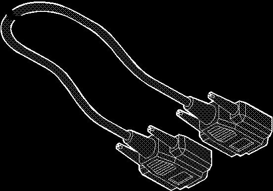
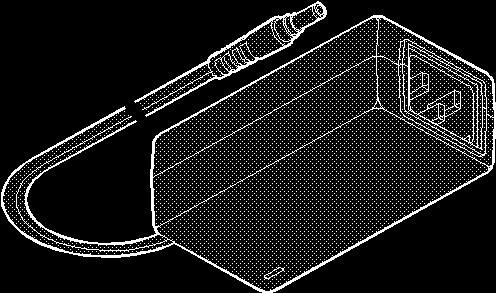
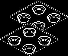
7 1.1 Supplied items LINDY KVM Extender C5 Pro Installation and Use page 7

8 LINDY KVM Extender C5 Pro Installation and Use page 8
9 2. Installation The installation of the Extender C5 set is straightforward and can best be achieved in most cases by following these stages for each module: Check or set the configuration switch settings Mount the module Connect the cables 2.1 Configuration switch settings The basic operations of the LOCAL and REMOTE modules are controlled by the banks of four switches located on the side of each module. The switches are monitored at all times and may be changed when power is on or off (the only exception to this rule is switch 1 of the LOCAL module which initiates slightly different functions depending on the power state when it is switched). LOCAL Switch 1 OFF: ON: ON: Normal operation (Before power is applied) Places the LOCAL module into flash upgrade mode so that the internal software can be changed. (See section 6. Flash upgrade procedure) (Whilst power is applied) Places the REMOTE module into password override mode. This allows any pre-configured passwords to be altered particularly useful when they have been lost or forgotten. (See section 5.5 Password override.) Note: When shipped, all switches are set in the OFF positions and this will produce normal operation with normal microphone input (at the REMOTE module.) LINDY KVM Extender C5 Pro Installation and Use page 9
10 LOCAL Switch 2 OFF: ON: Normal operation. Set transparent mode. Use this setting if the Extender C5 modules are to be used with KVM switches that are not manufactured by LINDY Electronics. Cascaded KVM switches often use special signals to set or identify conditions. In transparent mode, the Extender C5 modules will pass the signals without attempting to interpret them. LOCAL Switch 3 OFF: ON: Microphone input on REMOTE module. Use this setting if a standard mono-channel microphone is connected to the microphone input on the REMOTE unit. Stereo line-in input on REMOTE module. Use this setting if a stereo input is applied to the microphone input on the REMOTE unit. LOCAL Switch 4 OFF: ON: Normal operation. Suspend operation and reset the LOCAL module. Use this setting momentarily to produce the same effect as removing and restoring power if incorrect operation has occurred. Return the switch to the OFF position to allow normal operation to continue. LINDY KVM Extender C5 Pro Installation and Use page 10
 Note: When shipped, all switches are set in the OFF positions and this will produce normal operation.")
11 REMOTE Switch 1 OFF: ON: Normal operation. (Before power is applied) Places the REMOTE module into flash upgrade mode so that the internal software can be changed. (See section 6. Flash upgrade procedure) Note: When shipped, all switches are set in the OFF positions and this will produce normal operation. REMOTE Switches 2 and 3 Switches 2 and 3 determine which two keyboard keys (when pressed in unison) are to be designated as hotkeys. Hotkeys signal to the REMOTE module that the next key to be pressed is a special configuration command for the module and is not to be passed to the computer system. 2 OFF Hotkeys = CTRL and SHIFT 3 OFF 2 OFF Hotkeys = ALT and SHIFT 3 ON 2 ON Hotkeys = CTRL and ALT 3 OFF 2 ON Hotkeys disabled 3 ON REMOTE Switch 4 OFF: ON: Automatic video compensation mode. In this mode circuitry within the REMOTE module will adjust the video compensation settings automatically at power on to match the length of the cable run (providing the twisted pair to both modules is connected and both modules are switched on). Manual video compensation mode. Use this mode to bypass the automatic compensation circuitry if manual adjustment is required to improve the video quality. Automatic video compensation disabled. (Please see section 5.7 Video compensation. ) LINDY KVM Extender C5 Pro Installation and Use page 11
 Note: The module switches are not accessible once it is inserted into the rack, therefore, check")
12 2.2 Mounting a module desk or rack The Extender C5 modules can be situated on a desk (or floor) or alternatively, for larger installations, mounted within optional rack mount chassis units. Desk mount Rack mount Apply the supplied self-adhesive rubber feet to the underside of the module(s) Note: The module switches are not accessible once it is inserted into the rack, therefore, check all settings before insertion. 1 Place the rack securing plate (available as a separate kit) onto the front of the module and secure it with the two countersunk screws. 2 Orientate the module on its side so that its labelled face is the correct way up and the securing plate is facing away from the rack. 3 Slide the module into the required rack position. The rectangular cut-out in the front upper lip of the rack allows the two screws on the module s upper edge to slide through. 4 The rack mount chassis has a series of holes in its floor that are spaced to accommodate the two screws on the module s lower edge. Ensure that the screws correctly locate into the two holes of the chosen slot. The rack securing plate on the module should now be flush with the front of the rack mount chassis. 5 Use the third (pan-head) screw, in the top hole of the rack securing plate to fasten the module to the rack. LINDY KVM Extender C5 Pro Installation and Use page 12

13 3. Connections The naming of the LOCAL and REMOTE modules relate to their proximity to the computer system. Hence, the LOCAL module connects directly to the system, while the REMOTE is at the other end of the twisted pair cable and attaches to the keyboard, mouse, etc. Connections at the LOCAL module 3.1 KVM+A multi-cable connection Most of the connections between the computer system and the LOCAL module are made via the supplied multicable. This has a single connection to the module, is two metres in length and splits out to the keyboard, video, mouse, microphone and speaker ports of the system. 1. Attach the supplied KVM+A multi-cable to the 25-way socket at the end of the LOCAL module. 2. At the other end of the KVM+A cable, attach the keyboard, mouse and video, microphone, and speaker connectors to the appropriate sockets at the rear of the computer system. On most systems the appropriate ports should be labelled and colour coded in a similar way to the cable connectors: Monitor Keyboard Mouse Speaker Microphone Blue Purple Mid green Light green Pink (or maroon) LINDY KVM Extender C5 Pro Installation and Use page 13


14 3.2 Serial cable connection The Extender C5 set offers the option to attach an RS232 serial device (such as a touch screen input) via the remote link. The link supports software or hardware handshaking up to a maximum baud rate of 56 Kb/s. To make the serial connection between the LOCAL module and your computer system, use the supplied serial link cable. 1 Attach the male connector of the serial link cable to the 9 pin port on the LOCAL module. 2 Connect the other end of the serial link cable to the appropriate serial port of the computer system. 3.3 Twisted pair connection The link between the LOCAL and REMOTE modules is made via twisted pair cable, specified to Category 5 or higher. Ensure that the total twisted pair cable length (including patch boxes) does not exceed 200 metres. 1 Insert the connector from the twisted pair cable link into the socket. LINDY KVM Extender C5 Pro Installation and Use page 14


15 Connections at the REMOTE module 3.4 Keyboard, video and mouse connections The connections to the keyboard, video monitor and mouse are all made to the sockets at one end of the REMOTE module. 1 Attach the lead from the monitor to the blue D-type socket on the REMOTE module. 2 Connect the keyboard lead to the purple mini-din socket on the REMOTE module. 3 Insert the keyboard lead into the green mini-din socket on the REMOTE module. 3.5 Twisted pair, power and serial connections 1 Insert the connector from the twisted pair cable link into the socket. 2 Attach the output connector of the power supply to the socket at the front edge of the REMOTE module. 3 Insert the IEC connector of the supplied power lead into the corresponding socket of the power supply. Connect the other end of the power lead into a nearby mains socket. 4 If the serial connection to be used, attach the lead from your serial device to the 9 way male connector on the REMOTE module. LINDY KVM Extender C5 Pro Installation and Use page 15

16 3.6 Audio connections Audio connections are available at the two 3.5 jack sockets mounted on the side (same side as the switch bank) of the REMOTE module. Note: The microphone input has a dual function whereby it can either support a mono-channel microphone or alternatively receive stereo line input. Switch 3 on the LOCAL module controls the setting of this port: LOCAL switch 3 OFF - microphone, LOCAL switch 3 ON - stereo line in. 1 Connect the microphone (or stereo line input) plug into the REMOTE module microphone socket. (Note: Ensure that the setting of switch 3 on the LOCAL module matches the input to this socket: OFF - microphone; ON stereo line input) 2 Connect the speaker plug to the REMOTE module speaker socket. LINDY KVM Extender C5 Pro Installation and Use page 16

17 Note: When the REMOTE module is rack mounted, the audio connections must be made after the module has been fixed in place. Access is required to the rear and above the rack. Remember to remove the audio connections before attempting to slide out the REMOTE module. LINDY KVM Extender C5 Pro Installation and Use page 17

18 4. Operation 4.1 Power and activity indicators On the front panel of both modules are small recessed indicators which provide confirmation of power and activity, as follows: Constant red power applied, no communication activity. Flickering red - power applied, mouse or keyboard activity occurring. Slow flashing red module is in flash upgrade mode. Note: Both modules contain internal automatic cut-out fuses to protect against power surges. To reset, remove power (or, for the LOCAL module, the keyboard connection) from the module for one second and then reconnect. General Use In use, the Extender C5 modules should be transparent - the system and its peripherals should operate exactly as normal, the only difference being that they are now up to 200 metres apart. In some installations, you may see some shadows to the right of high contrast screen characters. This is caused by an incorrectly selected video compensation setting. In the majority of cases the automatic video compensation circuitry will correct such occurrences. However, it may be necessary to manually adjust the video compensation settings or in extreme cases to install an optional correction module. (See section 5.7 Video compensation. ) LINDY KVM Extender C5 Pro Installation and Use page 18
19 4.2 Locking and unlocking the system In situations where the computer system (and the LOCAL module) can be locked away the Extender C5 set offers a viable security system to deter unauthorised use. Once a password has been set, a simple key sequence allows the system to be quickly and securely detached from its peripherals. Only the correct password will reconnect the remote and local modules. To lock the system 1 First set a password. For further details, please refer to section 5.4 Password setting. 2 Simultaneously press the currently configured hotkeys (by default, b and j)along with L. The screen will go blank and the three keyboard indicators will begin alternately flashing between the Num Lock and Scroll Lock, and Caps Lock. This sequence indicates that a password is required. To unlock the system 1 Enter the correct password and press f. Note: Passwords are NOT case sensitive. Note: If an invalid password has been entered and the keyboard indicators are not flashing as described above press f to clear the incorrect attempt. 2 If the correct password is entered, the screen will be restored and normal operation can continue. To enable the video Simultaneously press the currently configured hotkeys (by default, b and jalong with 1. This command will be required to restore the video if b and jalong with L is used when no password has been set. To disable the video Simultaneously, press the currently configured hotkeys (by default, b and j) along with 0. LINDY KVM Extender C5 Pro Installation and Use page 19
20 5. Special configuration 5.1 Configuration You can alter the way that the Extender C5 modules operate to suit your requirements. This is done using the configuration mode and you can affect the following settings: Password setting allows you to lock the remote module to prevent unauthorized system access. Mouse restoration and settings allows you to restore mouse operation and also to change the mouse type. Video compensation allows you to manually adjust the video compensation settings. Miscellaneous functions 5.2 What are hotkeys? Hotkeys are two normal keyboard keys that, when pressed simultaneously with a third key, signal to the Extender C5 modules that you are sending a message specifically to them and not to the computer. The hotkeys are ordinarily b and j, while the third key determines what you want the modules to do. If the standard b and j hotkeys are also needed for computer tasks, you can change them for another combination using switches 2 and 3 on the REMOTE module: 2 OFF Hotkeys = b and j (default setting) 3 OFF 2 OFF Hotkeys = a and j 3 ON 2 ON Hotkeys = b and a 3 OFF 2 ON Hotkeys disabled 3 ON LINDY KVM Extender C5 Pro Installation and Use page 20
21 5.3 Entering, using and exiting configuration mode To enter and use configuration mode: 1 Simultaneously press the currently configured hotkeys (by default, b and j) along with f The three keyboard indicators ( Num Lock, Caps Lock and Scroll Lock ) will now begin to flash in sequence to show that you are in configuration mode. 2 Press the first letter of the required configuration option, for instance F All three keyboard indicators will illuminate continuously. Num Lock Caps Lock Scroll Lock 3 Press the number of the required configuration option, for instance 8 The Scroll Lock indicator will extinguish, leaving the Num Lock and Caps Lock indicators lit. Num Lock Caps Lock Scroll Lock 4 Press f to confirm your option The three keyboard indicators ( Num Lock, Caps Lock and Scroll Lock ) will now begin to flash in sequence again. To exit from the configuration mode: 1 Within configuration mode, the three keyboard indicators should be flashing in sequence to show that the module is ready to receive a new command. 2 Press f. The three indicators will return to their normal states. LINDY KVM Extender C5 Pro Installation and Use page 21
22 5.4 Password setting Password protection allows you restrict access to the system only to authorised personnel. A password first needs to be set and then, using the keyboard attached to the REMOTE module, a simple key sequence allows the system to be quickly and securely detached from its peripherals. To set a password 1 Simultaneously, press the hotkeys (by default, b and j) along with f to enter configuration mode. 2 Press P followed by f. 3 Now enter your new password, within the following constraints: Passwords are NOT case sensitive, Passwords may be any length from 1 character to a maximum of forty characters, The following keys may NOT be used: b, a, j or f. 4 When you have entered the password, press f to signal its completion. 5 Press f once more to exit configuration mode. For full details about how to lock and unlock the system using your password, please see section 4.2 Locking and unlocking the system. 5.5 Password override This mode allows you to override the password that has been set at the REMOTE module and place it into configuration mode so that a new one may be set. This feature is particularly useful when passwords have been lost or forgotten. To override the REMOTE password 1 Remove power from the REMOTE module. 2 With power to the system and LOCAL module still applied, change LOCAL switch 1 to the ON position. 3 Re-apply power to the REMOTE module. The REMOTE module will go directly into configuration mode so that the old password can be cleared and a new one set. To clear a password: (within configuration mode) Press P followed by f and followed by f again. You can now enter a new password using the procedure outlined in steps 2 to 5 of section 5.4 Password setting, or press f to exit configuration mode. 4 Return LOCAL switch 1 to it s OFF position. Note: If switch 1 remains ON, then the REMOTE module will enter configuration mode whenever it is repowered and will not operate normally. LINDY KVM Extender C5 Pro Installation and Use page 22
23 5.6 Hot plugging and mouse restoration It is strongly recommended that you switch off the computer system before attempting to connect it via the Extender C5 modules. However, if this is not possible then you need to hot plug the Extender C5 modules while power is still applied to the system. There is not normally a danger of damage to the system, however, when mouse communications are interrupted, often they fail to reinitialise when reconnected. Extender C5 modules provide a feature to reinstate mouse communications once the necessary connections have been made. There are two main types of data formats used by current PC mice; these are the older PS/2 format and the more recent IntelliMouse format introduced by Microsoft. These use slightly different data arrangements and it is important to know which type was being used before you hot-plugged the Extender C5 modules. The previous setting depends both on the type of mouse and the type of driver as various combinations of PS/2 and IntelliMouse are possible. Using the incorrect restore function may produce unpredictable results and require the system to be rebooted. Which restore setting do I use? The general rule is that unless both the mouse and the driver are both IntelliMouse compatible then you need to restore the mouse as PS/2. Recognising an IntelliMouse style mouse The IntelliMouse format was introduced to support, among other features, the scroll wheel function. If your mouse has a scroll wheel, then it is likely to support the IntelliMouse format. If you have a Microsoft mouse, then it will usually state that it is an IntelliMouse on its underside label. Recognising an IntelliMouse driver Before hot plugging your Extender C5 (or afterwards using only keyboard control), access the Windows Control Panel and select either the Mouse option (on Windows NT, 2000 and XP) or the System option (on Windows 95, 98, ME). Look for the name of the driver, which will usually include the words PS/2 or IntelliMouse. LINDY KVM Extender C5 Pro Installation and Use page 23
24 To restore mouse operation when hot plugging: 1 Carefully connect the Extender C5 modules to the system and its keyboard, mouse, monitor, audio and serial device. 2 Simultaneously, press the hotkeys (by default, b and j) along with f to enter configuration mode. 3 Enter the appropriate restore function code: PS/2 press M 6 f IntelliMouse press M 7 f 4 To exit configuration mode, press f. 5 Move the mouse a short distance and check for appropriate onscreen cursor movement. If the mouse cursor darts erratically around the screen, then cease moving the mouse. This is an indication that the chosen restore function is incorrect. Try again using the other restore function. Note: The restore functions predict the likely mouse resolution settings but may not restore the exact speed or sensitivity settings that were originally set. Microsoft and Logitech specific mouse settings In certain installations some Logitech mouse drivers may lose the action of the mouse buttons when used with the standard Microsoft compatible signalling protocol used between the modules. To solve this problem, select the Logitech compatible mouse signalling protocol. To change mouse signalling protocols 1 Simultaneously, press the hotkeys (by default, b and j) along with f to enter configuration mode. 2 Enter the appropriate protocol code: Microsoft compatible press M 3 f Logitech compatible press M 4 f 3 To exit configuration mode, press f LINDY KVM Extender C5 Pro Installation and Use page 24

25 5.7 Video compensation The Extender C5 incorporates video compensation circuitry to maximise the picture quality for any given length of twisted pair cable. The amount of video compensation required increases proportionally with the length of cable run that is being used. The Extender C5 can automatically correct the video compensation settings for any length of cable, however in certain circumstances you may wish to finely adjust and fix the compensation level to suit personal preferences - this can be done by switching to manual compensation mode. To display a suitable high contrast image The best way to clearly view the effects of compensation is to display a high contrast image, with vertical edges, on the screen. Open a word processor, type the capital letter H, or M and increase the point size to 72 or higher. For best results, the background should be white and the character should be black. A BLACK shadow on the right of the character indicates UNDER compensation. A WHITE shadow on the right of the character indicates OVER compensation. LINDY KVM Extender C5 Pro Installation and Use page 25
26 To manually adjust the video compensation 1 Change REMOTE switch 4 to the ON position. 2 Simultaneously, press the hotkeys (by default, b and j) along with f to enter configuration mode. The three keyboard indicators ( Num Lock, Caps Lock and Scroll Lock ) will now begin to flash in sequence. The speed of the sequence indicates the level of compensation currently applied: the slower the rate, the less compensation is being applied. 3 While watching the displayed high contrast screen image, now adjust the video compensation setting using the following keys: Optionally press F 2 f to make the circuitry calculate and apply an automatic compensation level you can use this as a starting point for your fine tuning. Press w to increase compensation by one fine step, Press { to increase compensation by one coarse step, Press g to select the neutral setting (no compensation), Press } to decrease compensation by one coarse step, Press y to decrease compensation by one fine step. Note: If the monitor goes blank and switches off (due to extreme over compensation) press the g key to restore it. 4 When no shadows are visible and the displayed images have crisp edges, press f to exit configuration mode. The new compensation setting will be stored, even when power is removed or if a complete reset is initiated. The setting should not require further changes, unless the cabling arrangement is altered. Note: If REMOTE switch 4 is returned to it s OFF position, the video compensation level will be recalculated and set at the next power on. LINDY KVM Extender C5 Pro Installation and Use page 26
 consists of four pairs of cables.")
27 If video compensation cannot solve the problem If automatic and manual compensation is unable to solve the problem, an additional module called a Skew Compensator may be required. Please see the next section for details. 5.8 The Skew Compensator The twisted pair cabling supported by the Extender C5 set (category 5, or higher) consists of four pairs of cables. Three of these pairs are used by the modules to convey red, green and blue video signals to the remote video monitor. Due to the slight difference in twist rate between these three pairs, the red, green and blue video signals may not arrive at the monitor together. This is visible as seperate colour shadows on high contrast screen images. This effect is particularly apparent when using higher screen resolutions and some types of category 5e cables. In this situation, Lindy recommend the use of an optional module called the Skew Compensator (Part No ). This manually adjustable, passive device can apply fine timing changes to the video signals ensuring they arrive together thus removing the colour separation. The REMOTE module includes a skew report function that indicates how to set the multiple switches on the Skew Compensator. This report function can also be a useful tool in determining if a skew compensator is required. LINDY KVM Extender C5 Pro Installation and Use page 27
. 2 Open an application that can display typed keys as screen characters - e.g. a word processor or Windows Notepad.")
28 5.9 To produce a skew compensator report 1 Ensure that the video image is correctly compensated using the procedure outlined in the previous section (the report will be more accurate if internal compensation is correctly applied). 2 Open an application that can display typed keys as screen characters - e.g. a word processor or Windows Notepad. The skew report will be written to the application by generating a series of faked key presses. 3 Simultaneously, press the hotkeys (by default, b and j) along with f to enter configuration mode. 4 Enter one of the following codes, depending on the type of keyboard being used: QWERTY keyboard (i.e. English, German), press F 3 AZERTY keyboard (French), press F 4 The screen will go blank for a few seconds whilst the measurements are made. When the picture is restored, a report, similar to that shown below will be generated. 5 Press f to exit configuration mode. Communicate the report findings to LINDY technical support for full advice on whether a Skew Compensator is required. LINDY KVM Extender C5 Pro Installation and Use page 28
29 5.10 Miscellaneous settings The following are configuration settings within the modules that are not covered in other sections of this guide. These can be achieved once within configuration mode by pressing the indicated keys: Report Extender C5 firmware version - F 1 f Before initiating this command, ensure that the system is running an application that can display typed keys as screen characters - e.g. a word processor or Windows Notepad. The current firmware version will be written to the application in the form of the letter V followed by three numbers - for example V118 means version Reset all configuration options to default states F 8 f Returns all user configurable options to the settings that are installed at manufacture. The password will be cleared; however, the current video compensation setting will not be reset. LINDY KVM Extender C5 Pro Installation and Use page 29
30 6. Flash upgrade procedure As part of the continual development and improvement process across the range of LINDY products, software upgrades are occasionally made available. The LOCAL and REMOTE modules both contain internal flash memory and LINDY s unique keyboard-link upgrade technique allows you to utilise software upgrades in a straightforward manner. Note: It is important to upgrade both the LOCAL and REMOTE modules together so that they are both running the same new version of software. Note: To upgrade the REMOTE module, a special keyboard connection cable is required. This cable must have 6pin mini-din male to 6pin mini-din male plugs with all lines connected - this is a common cable used with KVM switches. To perform a flash memory upgrade, you need to perform the following stages: Download upgrade files from the LINDY website Create a startup diskette and copy the files to it Reconfigure the LOCAL module connections and begin Reconfigure the REMOTE module connections and begin Return all connections to their usual states 6.1 Download the upgrade files To download the files 1 Access the LINDY Electronics Ltd. website ( enter the download section. Choose the upgrade option that best suits your requirements and download it to your system. 2 Decompress the downloaded file. Depending on the chosen option, there will be collection of suitable files. As a minimum, there should be the following files: AUTOEXEC.BAT directs the computer to run the upgrade programs. XKVMxxx.EXE this is the upgrade program that automatically determines which module is connected and sends the appropriate firmware file. XGLOCxxx.HEX this is the firmware file for the LOCAL module. XGREMxxx.HEX this is the firmware file for the REMOTE module. Where xxx is the upgrade version number. LINDY KVM Extender C5 Pro Installation and Use page 30
31 6.2 Create a startup disk For this stage you will need a blank 3½ floppy diskette that is either blank or has existing contents that are no longer required. Depending on your operating system, use one of the following to create a startup disk: To create a startup disk in Windows XP 1 Insert a disk into the floppy disk drive. 2 Select Start and then My Computer. 3 Right mouse click on the 3½ Floppy (A:) icon and select Format. 4 Check the Create an MS-DOS startup disk box and select Start. To create a startup disk in Windows 95/98/Me 1 Insert a formatted disk into the floppy disk drive. 2 Select Start, then Settings and then Control Panel. 3 Double click on the Add/Remove Programs icon. 4 Select the Startup Disk tab. 5 Click Create Disk and follow the instructions. To create a startup disk in Windows 95/98 (alternative method) 1 Insert a disk into the floppy disk drive. 2 Right mouse click on the 3½ Floppy (A:) icon and select Format. 3 Select the Full format option and ensure that the Copy system files box is checked. 4 Select Start to format the disk. To create a startup disk from MS-DOS or a DOS window within Windows 95/98 1 Insert a disk into the floppy disk drive and check that the drive is configured as drive A (it usually is). 2 At the DOS prompt (C:\>) type: FORMAT A: /S and follow the instructions given by DOS. Copy the downloaded files to the disk Once the diskette has been formatted, using Windows Explorer or the My Computer option, copy the downloaded and decompressed files from your computer to the floppy diskette. LINDY KVM Extender C5 Pro Installation and Use page 31

32 6.3 Reconfigure the LOCAL connections and begin 1 On the computer from which you will run the upgrade, ensure that its BIOS settings will allow it to boot from the floppy disk drive, rather than booting immediately from the hard drive. 2 Switch off the computer and disconnect the twisted pair cable from the LOCAL module. 3 On the KVM+A multi-cable, leave the keyboard connector attached to the keyboard port of the computer. Disconnect the KVM+A multi-cable video and mouse connectors from the ports on the computer. 4 So that you can check the upgrade progress, connect a monitor directly to the video port of the computer. 5 On the LOCAL module, change switch 1 to the ON position. Ensure that the upgrade disk is in the floppy disk drive of the computer. 6 Switch on the computer. The upgrade process will start automatically and confirmation will be given on screen. 7 Switch off the computer and disconnect the KVM+A multi-cable. Leave the monitor connected and the upgrade disk in the floppy disk drive. LINDY KVM Extender C5 Pro Installation and Use page 32
 not supplied. Attach one end of the cable to the keyboard port of the computer.")
33 6.4 Reconfigure the REMOTE connections and begin 1 Disconnect all cables from the REMOTE module and take it to the computer. 2 Use a KVM switch-type keyboard cable (6 pin mini-din male to 6 pin mini-din male plugs with all lines connected) not supplied. Attach one end of the cable to the keyboard port of the computer. Connect the other end of the cable to the keyboard port of the REMOTE module. This is the only connection required. 3 On the REMOTE module, change switch 1 to the ON position. 4 Attach the power supply unit to the POWER input of the REMOTE module and connect the mains lead to a nearby wall socket. 5 Switch on the computer. The upgrade process will start automatically and confirmation will be given on screen. 6 Switch off the computer and disconnect the REMOTE module. Return REMOTE switch 1 to the OFF position. 6.5 Return all connections to their usual states Once the upgrade process has been completed, perform the following to return the system to its previous state. 1 Ensure that switch 1 on both the LOCAL and REMOTE modules is set to the OFF positions. 2 Refer to section 3 Connections for detailed instructions on correctly connecting the LOCAL and REMOTE modules to the computer, its peripherals, the REMOTE power supply and the twisted-pair cable. 3 Remove the diskette from the system and reboot. The upgrade process is now complete. LINDY KVM Extender C5 Pro Installation and Use page 33
34 7. Troubleshooting If you experience problems when installing or using the Extender C5 modules please check through this section for a possible solution. Video image at the REMOTE module is distorted or shadows appear to the right of displayed objects. Video compensation is required to compensate for the length of the twisted pair cable being used. If video problems persist: Please refer to section 5.7 Video compensation. If the overall video image is fuzzy and/or has coloured shadows you may need to use the optional C5 Series Skew Compensator. This stand-alone passive module allows you to finely tune the red, green and blue video signal timings (each of which is fed along separate twisted pairs) to overcome most colour separation problems. Please refer to section 5.8 Skew Compensator. No video image is received at the REMOTE module Check that the power/activity indicators are lit on the LOCAL and REMOTE modules - if they are not, then there is a power problem. When keys are pressed or the mouse is moved, check that the indicators flicker if they do not then there could be a twisted pair link problem or a problem with one of the modules. Check that the Category 5 (or higher) cable is wired correctly as per the diagram in the section 5.8 Skew Compensator. If possible, try using an alternative twisted pair connection between the modules. If the REMOTE module is severely over compensated, the monitor may not be able to display a picture. Try manually reducing the video compensation. Please refer to section 5.7 Video compensation. Temporarily disconnect the video link to the LOCAL module, connect a monitor directly to the computer video port and check for a correct video image output. Power is applied via the power supply but REMOTE module operation has stopped. Each module has an internal automatic cut-out fuse to protect against power surges. To reset, remove power from the module for one second and then reconnect. The on-screen mouse pointer does not respond to mouse movements The mouse connection may have been interrupted. Either, reboot the system and re-power the REMOTE module power supply, or try using the mouse restoration command. Please refer to section 5.6 Hot plugging and mouse restoration. LINDY KVM Extender C5 Pro Installation and Use page 34
35 Sound from the microphone cannot be heard or is very quiet Check the setting of LOCAL switch 3 if a microphone is connected at the REMOTE module, the switch should be set to OFF. Sound input from the stereo line input is distorted and only one channel is working Check the setting of LOCAL switch 3 if a stereo line input is connected at the REMOTE module, the switch should be set to ON. LINDY KVM Extender C5 Pro Installation and Use page 35
36 8. Extender C5 Accessories The following related C5 Series items are available: LINDY C5 Skew Compensator (Part No ) Removes colour split in video signals caused by certain Cat 5e and 6 cables. Required only in certain installations with long cable lengths and high video resolutions. LINDY C5 Series Rack mount chassis (Part No ) This 19 chassis allows multiple C5 Series modules to be neatly arranged within a standard cabinet. Securing plates and screws are supplied separately. LINDY C5 Series Power distribution module (Part No ) Provides power for up to four C5 Series modules to reduce mains power socket requirements. LINDY C5 Series Rack mount securing plates For Extender C5 Local module (Part No ) For C5 Series Skew Compensator (Part No ) C5 Single Blanking Plate (Part No ) C5 Quad Blanking Plate (Part No ) LINDY KVM Extender C5 Pro Installation and Use page 36
AdderLink X-Series. Gold Extender
 AdderLink X-Series Gold Extender CONTENTS Contents Welcome Introduction... 2 Supplied items... 3 Installation and operation Installation... 4 Stage A - Configuration switch settings... 4 LOCAL module switches...
AdderLink X2 Multi Screen
 AdderLink X2 Multi Screen Remote Extenders LOCAL MULTISCREEN REMOTE MULTISCREEN VIDEO IN 4 VIDEO IN 3 VIDEO OUT 4 VIDEO OUT 4 www.adder.com VIDEO OUT 3 www.adder.com VIDEO IN 2 VIDEO OUT 3 VIDEO OUT 2
AdderLink X2 Dual Access
 AdderLink X2 Dual Access Remote Extenders LOCAL DUAL ACCESS TO REMOTE POWER LOCAL SILVER DUAL ACCESS TO REMOTE POWER www.adder.com www.adder.com VIDEO OUT VIDEO OUT CPU / KVM SWITCH CPU / KVM SWITCH CONTENTS
ServSwitch Wizard Extenders
 NETWORK SERVICES October 2005 ACU5112A ACU5110A ACU5010A-R2 ServSwitch Wizard Extenders CUSTOMER SUPPORT Order toll-free in the U.S.: Call 877-877-BBOX (outside U.S. call 724-746-5500) FREE technical support
ServSwitch Wizard Extenders
 NETWORK SERVICES July 2005 ACU5122A ACU5142A ServSwitch Wizard Extenders CUSTOMER SUPPORT INFORMA- Order toll-free in the U.S. 24 hours, 7 A.M. Monday to midnight Friday: 877-877-BBOX FREE technical support,
AdderLink X2 Dual Access
 AdderLink X2 Dual Access Remote Extenders LOCAL DUAL ACCESS TO REMOTE POWER LOCAL SILVER DUAL ACCESS TO REMOTE POWER www.adder.com www.adder.com VIDEO OUT VIDEO OUT CPU / KVM SWITCH CPU / KVM SWITCH CONTENTS
AdderLink X2 Multi Screen
 AdderLink X2 Multi Screen Remote Extenders LOCAL MULTISCREEN REMOTE MULTISCREEN VIDEO IN 4 VIDEO IN 3 VIDEO OUT 4 VIDEO OUT 4 www.adder.com VIDEO OUT 3 www.adder.com VIDEO IN 2 VIDEO OUT 3 VIDEO OUT 2
AdderLink X50 USB. User.Guide. contents ADDER LOCAL POWER OUT LINK TO REMOTE
 AdderLink X50 USB User.Guide OUT TO REMOTE LOCAL ADDER contents Contents Welcome Introduction...2 Supplied items...3 Optional items...4 Installation Connections...5 Mounting...5 Connections at the local
AdderLink X-USBPRO. Analog video and USB extenders
 AdderLink X-USBPRO Analog video and USB extenders Contents Welcome Introduction...2 Supplied items...3 Optional items...4 Installation Connections...5 Mounting...5 Connections at the local module...6 Local
16 Port SMART View PRO SV16PRO 12 Port SMART View PRO SV12PRO 8 Port SMART View PRO SV8PRO 4 Port SMART View PRO SV4PRO U S & O N T I
 SMARTViewPRO E U S & I N S T A L L A T I O N 16 Port SMART View PRO SV16PRO www.addertec.com SMARTViewPRO 12 Port SMART View PRO SV12PRO 8 Port SMART View PRO SV8PRO 4 Port SMART View PRO SV4PRO About
U S & O N T I L A T A L I N S. SMART View 2 SV4. SMARTView SV2.
 SMARTView E U S & I N S T A L L A T I O N www.addertec.com SMARTView SMART View 4 SMART View 2 SV4 SV2 About this manual SmartView - Installation and Use Sixth edition (April 1999) Part No. ADD0026/6 (c)
AdderLink X-USBPRO. Analog video and USB extenders
 AdderLink X-USBPRO Analog video and USB extenders Contents Welcome Introduction...2 Supplied items...3 Optional items...4 Installation Connections...5 Mounting...5 Connections at the local module...6 Local
AdderLink X-DVI. Digital video and USB extenders ADDER REMOTE LINK TO LOCAL UPG
 2 3 4 AdderLink X-DVI Digital video and USB extenders TO LOCAL REMOTE UPG ADDER 1 CTENTS Contents Welcome Important link cable advice...2 What s in the box...3 What you may additionally need...3 Installation
Connectivity Peripherals User s Guide. Point 510 Point 1600
 Connectivity Peripherals User s Guide Point 510 Point 1600 Connectivity Peripherals User s Guide Point 510 Point 1600 Fujitsu Personal Systems, Inc. has made every effort to ensure the accuracy and completeness
LINDY CPU SWITCH DUAL JUNIOR MANUAL
 LINDY CPU SWITCH DUAL JUNIOR MANUAL LINDY Part.No. 32351 LINDY CPU Switch Dual Junior 8 Port LINDY Part.No. 32352 LINDY CPU Switch Dual Junior 16 Port About this manual LINDY CPU Switch Dual Junior - Installation
Installation Guide. Wyse Rx0L Thin Client Flash and RAM Upgrade Option Kit. Issue: PN: L Rev. A
 Installation Guide Wyse Rx0L Thin Client Flash and RAM Upgrade Option Kit Issue: 052209 PN: 883884-11L Rev. A ii Copyright Notice 2009, Wyse Technology Inc. All rights reserved. This manual and the software
Adder CCS4-USB. Four-port keyboard and mouse switch
 Adder CCS4-USB Four-port keyboard and mouse switch CONTENTS Contents Welcome Introduction...2 What is True Emulation?...3 Adder CCS4 features - top and rear...4 What s in the box...5 What you may additionally
AdderLink X-DVIPRO-DL
 AdderLink X-DVIPRO-DL User Guide Experts in Connectivity Solutions KVM Extender Solutions Contents Introduction Welcome...2 Cable type and distance rules...2 Supplied items...3 Optional extras...4 Installation
Installer/User Guide
 Installer/User Guide Avocent Corporation 4991 Corporate Drive Huntsville, Alabama 35805-6201 USA 256-430-4000 (Fax) 256-430-4030 http://www.avocent.com FCC Notification Warning: Changes or modifications
SmartView Multiscreen Serial
 SmartView Multiscreen Serial Four-port KVM and serial switch SMARTVIEW MULTISCREEN CONTENTS Contents Welcome Introduction...2 Serial line switching...2 Standard items...3 Additional and optional items...4
Technology Corporation. ADDERLINK X SERIES X2-MultiScreen
 ADDERLINK X SERIES X2-MultiScreen Multiple video, multiple RS232, keyboard, mouse and audio extender, with local access, giving sharp, bright and ultra high-resolution video images at distances up to 300m
If anything is damaged or missing, contact your dealer.
 User Manual CS-64A Read this guide thoroughly and follow the installation and operation procedures carefully in order to prevent any damage to the unit and/or any devices that connect to it. This package
Allworx Tx 92/24 Telephone Expander Installation Guide
 Allworx Tx 92/24 Telephone Expander Installation Guide No part of this publication may be reproduced, stored in a retrieval system, or transmitted, in any form or by any means, electronic, mechanical,
DVI KVM Switch user manual Model
 DVI KVM Switch user manual Model 156066 INT-156066-UM-0808-01 introduction Thank you for purchasing the INTELLINET NETWORK SOLUTIONS DVI KVM Switch, Model 156066. This convenient device lets you control
USB USB Data Transfer
 DECEMBER 2000 IC149A-R2 USB USB Data Transfer USB to USB Data Transfer CUSTOMER SUPPORT INFORMATION Order toll-free in the U.S. 24 hours, 7 A.M. Monday to midnight Friday: 877-877-BBOX FREE technical support,
USB/VGA Cat 5 UTP Long Range Console Extender
 USB/VGA Cat 5 UTP Long Range Console Extender SV565UTPUL *actual product may vary from photos FCC Compliance Statement This equipment has been tested and found to comply with the limits for a Class B digital
Messager USB by Nel-Tech Labs, Inc. Installation & User Manual
 Messager USB by Nel-Tech Labs, Inc. Installation & User Manual Index: Introduction... 3 Messager USB Layout Summary... Installation... Message Programming & Operation... Troubleshooting... 4 5 6 6 Warranty
HomePlug Ethernet Bridge
 HomePlug Ethernet Bridge User Manual English LINDY No. 25120 www.lindy.com LINDY ELECTRONICS LIMITED & LINDY-ELEKTRONIK GMBH - SECOND EDITION (Feb 2004) Introduction Thank you for purchasing a LINDY HomePlug
Installation Guide AVA-2902E/I. PCI-to-Fast SCSI Host Adapters. PCI SCSI Host Adapter with Internal or External Connector
 Installation Guide AVA-2902E/I PCI-to-Fast SCSI Host Adapters PCI SCSI Host Adapter with Internal or External Connector R 1 Installing the Host Adapter and SCSI Device WARNING: Before you start, turn OFF
CHS 7Ci. Bluetooth Cordless Barcode Scanner. Quick Start Guide
 Quick Start Guide CHS 7Ci Bluetooth Cordless Barcode Scanner www.socketmobile.com PACKAGE CONTENTS Product Information Product label Blue/Green/Red LED Scanner head Trigger button CHS 7Ci Lanyard NiMH
AV4PRO-VGA AV4PRO-VGA-DUAL AV4PRO-VGA-TRIPLE {AV4PRO-VGA-QUAD. AdderView PRO. User Guide COMPUTER KVM SPK USB1 USB2 MODE.
 AdderView PRO User Guide AV4PRO-VGA AV4PRO-VGA-DUAL AV4PRO-VGA-TRIPLE {AV4PRO-VGA-QUAD COMPUTER KVM SPK USB1 USB2 MODE www.adder.com CONTENTS Contents Introduction What is True Emulation?...3 AdderView
4 Port KVM Switch. If anything is damaged or missing, contact your dealer.
 4 Port KVM Switch User Manual CS-84A Read this guide thoroughly and follow the installation and operation procedures carefully in order to prevent any damage to the units and/or any devices that connect
1.0 Description. 2.0 Unpacking. 3.0 Installation
 ES-H, ES-HA Series Precision Balance Thank you for purchasing the Model ES-H and ES-HA precision balance. Please read all operating instructions carefully before using and note the following items to ensure
User Guide CPSMP VAC Power Supply Module: PointSystem CPSMC Accessory CPSMC Accessory. Contents.
 User Guide CPSMP-205 110 240 VAC Power Supply Module: PointSystem CPSMC1800-200 Accessory CPSMC1900-100 Accessory Contents Contents...1 Description...1 Cautions and Warnings...2 Definitions...2 Power supply
KVM Console Extender over Cat5 UTP
 KVM Console Extender over Cat5 UTP SV565UTP *actual product may vary from photos DE: Bedienungsanleitung - de.startech.com FR: Guide de l'utilisateur - fr.startech.com ES: Guía del usuario - es.startech.com
Savi Talk WT100/T Professional wireless headset system. (WT1/T base + WH100/T headset) with optional HL10 lifter User Guide
 with optional HL10 lifter User Guide") Savi Talk WT100/T Professional wireless headset system (WT1/T base + WH100/T headset) with optional HL10 lifter User Guide Welcome Congratulations on purchasing your new Plantronics product. This guide
Savi Talk WT100/T Professional wireless headset system (WT1/T base + WH100/T headset) with optional HL10 lifter User Guide Welcome Congratulations on purchasing your new Plantronics product. This guide
Ultra Slim Multimedia Keyboard (KB3100MF)
") User Manual USB and other connectors Keyboard Additional package contents: Quick Installation Guide User Manual Warranty Contents Installing your new keyboard Customizing keyboard hot keys Changing key
User Manual USB and other connectors Keyboard Additional package contents: Quick Installation Guide User Manual Warranty Contents Installing your new keyboard Customizing keyboard hot keys Changing key
If anything is damaged or missing, contact your dealer.
 User Manual CS-102 CS-122 Read this guide thoroughly and follow the installation and operation procedures carefully in order to prevent any damage to the unit and/or any devices that connect to it. This
PC Media Converter, Switching (TP-TX/FX)
") April 2006 LH6620C LH6621C LH6622C LH6623C PC Media Converter, Switching (TP-TX/FX) Copyright 2006. Black Box Corporation. All rights reserved 1000 Park Drive * Lawrence, PA. 35055-1018 * 724-746-5500
April 2006 LH6620C LH6621C LH6622C LH6623C PC Media Converter, Switching (TP-TX/FX) Copyright 2006. Black Box Corporation. All rights reserved 1000 Park Drive * Lawrence, PA. 35055-1018 * 724-746-5500
ADL-100 Operator s Manual
 040604-510896-(01) ADL-100 Operator s Manual For Use With the Accent Disc Laminator 2004 All rights reserved. Notices: The information in this document is subject to change without notice. NO WARRANTY
SySTIUM TECHNOLOGIES. Assembly Guide. Model 133i
 Assembly Guide Model 133i Radio Frequency Interference Notice (USA) This equipment has been tested and found to comply with the limits for a Class B digital device, pursuant to Part 15 of the FCC Rules,
AV4PRO-DVI AV4PRO-DVI-DUAL AV4PRO-DVI-QUAD. AdderView PRO. User Guide COMPUTER KVM SPK USB1 USB2 MODE.
 AdderView PRO User Guide { AV4PRO-DVI AV4PRO-DVI-DUAL AV4PRO-DVI-QUAD COMPUTER KVM SPK USB1 USB2 MODE www.adder.com CONTENTS Contents Introduction What is True Emulation?...3 AdderView PRO features - front
Introduction. Table of Content. Overview. Automatic Mouse Conversion. Introduction
 ----------------- Introduction Introduction Table of Content Overview......1 Features....2 Installations Console Connection....3 Computers Connection... 4 Initial Power-up....6 Operations Front Panel operation.........7
Monarch 939i Intelligent Keyboard
 Monarch 939i Intelligent Keyboard TC0939iOI Rev. AF 12/07 2004 Paxar Americas, Inc. a subsidiary of Avery Dennison Corp. All rights reserved. Each product and program carries a respective written warranty,
CS-64U. User Manual
 User Manual CS-64U Read this guide thoroughly and follow the installation and operation procedures carefully in order to prevent any damage to the units and/or any devices that connect to them. This package
INSTALLATION INSTRUCTIONS
 INSTALLATION INSTRUCTIONS READ THIS MANUAL CAREFULLY! FAILURE TO INSTALL THIS EQUIPMENT PER THESE INSTRUCTIONS WILL VOID THE WARRANTY. AM16904-1 Rev. C pg. 1 of 12 SPECIAL NOTICES The following notices
PS/2 & USB KVM Console Extender
 PS/2 & USB KVM Console Extender UTP KVM Signal Extender for Distances up to 500 feet (150 m) SV565UTP Actual product may vary from photo FCC Compliance Statement This equipment has been tested and found
Operating Instructions
 028028 Operating Instructions Monarch 939i Intelligent Keyboard for use with 9416 XL, 9906, ADTP1, and ADTP2 TC0939IOI Rev. AN 5/17 2004 Avery Dennison Corp. All rights reserved. Each product and program
Long Range VGA USB KVM Console Extender over Cat5 UTP ft
 Long Range VGA USB KVM Console Extender over Cat5 UTP - 1000 ft SV565UTPUL *actual product may vary from photos DE: Bedienungsanleitung - de.startech.com FR: Guide de l'utilisateur - fr.startech.com ES:
Instruction Guide. 2 Channel Ultra ATA/100 PCI Card PCI2IDE100. The Professionals Source For Hard-to-Find Computer Parts. Revised: December 5, 2002
 IDE CARD 2 Channel Ultra ATA/100 PCI Card PCI2IDE100 Instruction Guide * Actual product may vary from photo Revised: December 5, 2002 The Professionals Source For Hard-to-Find Computer Parts 7 FCC COMPLIANCE
AX3000 Platine Terminal Ethernet TCP/IP
 AX3000 Platine Terminal Ethernet TCP/IP Model 80 Installation Guide January 2012 - Ref: I80E0922-2 Model AX3000/M80 Type EA The reproduction of this material, in part or whole, is strictly prohibited.
2.5 SATA Drive Mobile Rack for 3.5 Bay - Anti-Vibration
 2.5 SATA Drive Mobile Rack for 3.5 Bay - Anti-Vibration SATBP125VP *actual product may vary from photos FR: Guide de l utilisateur - fr.startech.com DE: Bedienungsanleitung - de.startech.com ES: Guía del
2001BRF & 2001URF. Wireless Keyboard & Mouse Kit. User s Guide
 2001BRF & 2001URF Wireless Keyboard & Mouse Kit User s Guide Version 1.2 封面內頁 The information in this document is subject to change without notice and does not represent a commitment on the part of the
AX3000 Platine Terminal Ethernet TCP/IP
 AX3000 Platine Terminal Ethernet TCP/IP Model 80WMS Installation Guide January 2012 - Ref: I80ME0922-2 Model AX3000/M80M Type EA The reproduction of this material, in part or whole, is strictly prohibited.
If anything is damaged or missing, contact your dealer.
 User Manual CS-64U Read this guide thoroughly and follow the installation and operation procedures carefully in order to prevent any damage to the units and/or any devices that connect to them. This package
Copyright Black Box Corporation. All rights reserved Park Drive Lawrence, PA Fax
 Copyright 2003. Black Box Corporation. All rights reserved. 1000 Park Drive Lawrence, PA 15055-1018 724-746-5500 Fax 724-746-0746 AUI to 10BASE-FL Transceiver MAY 2003 LE1603A CUSTOMER SUPPORT INFORMATION
Computertop TV-I. Computertop TV-I SEPTEMBER 1993 AC451A CUSTOMER SUPPORT INFORMATION
 SEPTEMBER 1993 AC451A Computertop TV-I Computertop TV-I CUSTOMER SUPPORT INFORMATION Order toll-free in the U.S. 24 hours, 7 A.M. Monday to midnight Friday: 877-877-BBOX FREE technical support, 24 hours
Radio Mini Wireless Wheel Mouse User s Guide MODEL: RFMSW-15
 Radio Mini Wireless Wheel Mouse User s Guide MODEL: RFMSW-15 Trademark Recognition Windows, Office 97 and MS-IntelliMouse are registered trademarks of Microsoft Corp. RFMSW-15 THIS DEVICE COMPLIES WITH
DRD-4 DRD-4 JULY 1992 FX140A CUSTOMER SUPPORT INFORMATION
 JULY 1992 FX140A CUSTOMER SUPPORT INFORMATION Order toll-free in the U.S. 24 hours, 7 A.M. Monday to midnight Friday: 877-877-BBOX FREE technical support, 24 hours a day, 7 days a week: Call 724-746-5500
CS-231. User Manual. Copyright ATEN International Co., Ltd. Manual Part No. PAPE G Printing Date: 11/2006
 User Manual CS-231 Read this guide thoroughly and follow the installation and operation procedures carefully in order to prevent any damage to the units and/or any devices that connect to them. This package
USB Port Hub HO
 USB 2.0 7-Port Hub INSTRUCTION MANUAL HO97916 www.jascoproducts.com Table of Contents I. INTRODUCTION 3 II. OVERVIEW 4 III. SAFETY INSTRUCTIONS 5 IV. POWER MODE SETTING 6 V. HUB STAND ASSEMBLY 7 VI. HARDWARE
USER S MANUAL MODEL VP6630
 USER S MANUAL MODEL VP6630 Regulatory Compliance This device complies with Part 15 of the FCC Rules. Operation is subject to the following two conditions: (1) This device may not cause harmful interference,
AdderView Secure. User Guide INSERT CARD CHIP DOWNWARDS
 AdderView Secure User Guide 1 2 3 4 INSERT CARD CHIP DOWNWARDS ERR PWR CONTENTS Contents Welcome Introduction...2 AdderView Secure - features...3 Standard items...4 Additional items...4 Installation Locations...5
Lotus DX. sit-stand workstation. assembly and operation instructions. MODEL # s: LOTUS-DX-BLK LOTUS-DX-WHT
 Lotus DX assembly and operation instructions sit-stand workstation MODEL # s: LOTUS-DX-BLK LOTUS-DX-WHT safety warnings 13.6 Kg 30 lbs. 2.2 Kg 5 lbs. safety instructions/warning Read and follow all instructions
AVA AT-to-SCSI Host Adapter. Installation Guide
 R AVA-1505 AT-to-SCSI Host Adapter Installation Guide 1 Getting Started This guide tells you how to install and configure the AVA -1505 AT -to-scsi host adapter. Installation instructions are given in
Notebook Expansion USB home dock with audio pass-through USER GUIDE
 Notebook Expansion USB home dock with audio pass-through USER GUIDE Table of Contents Introduction... 3 Package Contents... 5 System Requirements... 5 Connecting the Notebook Expansion USB home dock with
Messager USB w/ Night Answer
 Messager USB w/ Night Answer Digital Messaging System Installation & Users Guide Attention! Some USB drives have indicator LEDs - These LEDs may blink slow, fast, or may stay solid during playback. Any
Enclosure TS-530 User Manual
 Enclosure TS-530 User Manual 16525 East Laser Drive Fountain Hills, AZ 85268 TEL 480.837.5200 FAX 480.837.5300 info@embeddedx86.com http://www.embeddedx86.com/ Technologic Systems, Inc. COPYRIGHT 1998-200
INSTALLATION GUIDE ADAPTEC SCSI CARD 29320LP
 INSTALLATION GUIDE ADAPTEC SCSI CARD 29320LP INTRODUCTION The Adaptec SCSI Card 29320LP enables you to connect up to 15 SCSI devices such as very large arrays of high-performance hard disk drives, external
Installation & User s Guide
 Wireless 5 button Optical Mouse Item Number: 11010887 Installation & User s Guide All brand names and trademarks are the property of their respective owners. FCC and CE Radiation Norm FCC This equipment
USB KVM Switch USER MANUAL CS62US / CS64US
 USB KVM Switch USER MANUAL CS62US / CS64US EMC Information FEDERAL COMMUNICATIONS COMMISSION INTERFERENCE STATEMENT: This equipment has been tested and found to comply with the limits for a Class B digital
USER GUIDE. AXIS T8120 Midspan 15 W 1-port ENGLISH
 USER GUIDE AXIS T8120 Midspan 15 W 1-port ENGLISH Legal Considerations Video and audio surveillance can be prohibited by laws that vary from country to country. Check the laws in your local region before
Item No.: 4SK108. User Manual. Thank you for choosing The Original Dash Cam. This manual offers detailed information on how to operate TODC (The
 Item No.: 4SK108 User Manual Thank you for choosing The Original Dash Cam This manual offers detailed information on how to operate TODC (The Original Dash Cam) WEE including: how to operate the device,
4-Port USB KVM Switch - DisplayPort - 4K 60Hz
 4-Port USB KVM Switch - DisplayPort - 4K 60Hz SV431DPUA2 *actual product may vary from photos FR: Guide de l utilisateur - fr.startech.com DE: Bedienungsanleitung - de.startech.com ES: Guía del usuario
A-01. Instruction Manual. Bluetooth Active Noise Cancelling Headphone
 A-01 Instruction Manual Bluetooth Active Noise Cancelling Headphone The user manual explains the features and functions of your A-01 to help ensure an optimal user experience. Product Specifications: Bluetooth
User Manual CL
 User Manual CL-1200 Warning! This is a class A product. In a domestic environment this product may cause radio interference in which case the user may be required to take adequate measures. This equipment
Cat. No KT/B. Installation Data
 Cat. No. 1784-KT/B Installation Data The 1784-KT/B Communication Interface Module allows personal computers, workstations or terminals to communicate with Allen-Bradley processors and controllers, either
Owner s Manual. DisplayPort KVM Switch with Audio and SuperSpeed USB 3.0 Hub. Models: B004-DPUA2-K, B004-DPUA4-K
 Owner s Manual DisplayPort KVM Switch with Audio and SuperSpeed USB 3.0 Hub Models: B004-DPUA2-K, B004-DPUA4-K Table of Contents Package Contents 2 Optional Accessories 2 System Requirements 2 Features
Folding Rackmount Console
 RACKCONS2001 Instruction Manual Folding Rackmount Console 1U 20.1 Folding LCD Rackmount Console - USB and PS/2 FCC Compliance Statement This equipment has been tested and found to comply with the limits
INSTALLATION GUIDE ADAPTEC SCSI CARD ULTRA160 SCSI CONTROLLER
 R INSTALLATION GUIDE ADAPTEC SCSI CARD 29160 ULTRA160 SCSI CONTROLLER Adaptec SCSI Card 29160 INTRODUCTION The Adaptec SCSI Card 29160 Ultra160 SCSI controller enables you to connect up to 15 SCSI devices
The OmniCube User Manual
 The OmniCube User Manual P72462 F1D094 Introduction Thank you for purchasing the Belkin Components OmniCube KVM (Keyboard Video Mouse) switch. Controlling four PCs from one keyboard, mouse and monitor
RED-PSU. User Guide. Power Solutions. Experts in Connectivity Solutions
 RED-PSU User Guide Experts in Connectivity Solutions Power Solutions Contents Introduction Welcome...2 Protection and control...2 5VDC converter dongles...2 Supplied items...3 Optional extras...3 Installation
VGA USB KVM Console Extender over CAT5 UTP (500 ft)
") VGA USB KVM Console Extender over CAT5 UTP (500 ft) SV565UTPU SV565UTPUGB SV565UTPUEU DE: Bedienungsanleitung - de.startech.com FR: Guide de l'utilisateur - fr.startech.com ES: Guía del usuario - es.startech.com
VGA USB KVM Console Extender over CAT5 UTP (500 ft) SV565UTPU SV565UTPUGB SV565UTPUEU DE: Bedienungsanleitung - de.startech.com FR: Guide de l'utilisateur - fr.startech.com ES: Guía del usuario - es.startech.com
Limited Warranty. All brand names and registered trademarks are the property of their respective owners.
 Limited Warranty IN NO EVENT SHALL THE DIRECT VENDOR'S LIABILITY FOR DIRECT OR INDIRECT, SPECIAL, INCIDENTAL OR CONSEQUENTIAL DAMAGES, LOSS OF PROFIT, LOSS OF BUSINESS, OR FINANCIAL LOSS WHICH MAY BE CAUSED
2 Port VGA USB KVM Switch with DDM and Cables 4 Port VGA USB KVM Switch with DDM and Cables SV231USBDDM SV431USBDDM
 2 Port VGA USB KVM Switch with DDM and Cables 4 Port VGA USB KVM Switch with DDM and Cables SV231USBDDM SV431USBDDM *actual product may vary from photos DE: Bedienungsanleitung - de.startech.com FR: Guide
User s Guide CPSMC0200-2x0 Dual-Slot PointSystem Chassis
 User s Guide CPSMC0200-2x0 Dual-Slot PointSystem Chassis The Transition Networks CPSMC0200-2x0 series dual-slot PointSystem chassis is designed for installation of one or two selectable Transition Networks
DATALOCKER H100 ENCRYPTED HARD DRIVE. User Guide
 DATALOCKER H100 ENCRYPTED HARD DRIVE User Guide CONTENTS Introducing DataLocker H100 Minimum System Requirements Device accessories DataLocker Documentation Getting Started Plugging in the device Personalizing
Installing and Configuring Rialto Analytic Appliances
 Installing and Configuring Rialto Analytic Appliances Important Safety Information This manual provides installation and operation information and precautions for the use of this camera. Incorrect installation
2DScan TM Barcode Scanner
 2DScan TM Barcode Scanner Quick Start Manual Default Check Version FCC WARNING STATEMENT This equipment has been tested and found to comply with the limits for a Class B digital device, pursuant to Part
AHA PCI-to-Fast SCSI Host Adapter. Fast SCSI Connection for High-Performance SCSI Peripherals for Pentium PCs
 R AHA-2920 PCI-to-Fast SCSI Host Adapter Fast SCSI Connection for High-Performance SCSI Peripherals for Pentium PCs Introduction This installation guide provides the instructions needed to install and
N331 Wireless Mini Optical Mouse User s Guide
 N331 Wireless Mini Optical Mouse User s Guide Mouse 1. Left mouse button 2. Right mouse button 3. Scroll wheel 4. Charge port 5. Battery cover 6. Receiver storage compartment 7. Battery cover release button
1999 ATEN Technology, Inc. All Rights Reserved.
 1999 ATEN Technology, Inc. All Rights Reserved. Microsoft and Windows 98 are registered trademarks of Microsoft Corporation. IBM is a registered trademark of International Business Machines, Inc. Macintosh,
Folding Rackmount Console
 Folding Rackmount Console 15 Folding LCD Rackmount Console 17 Folding LCD Rackmount Console 19 Folding LCD Rackmount Console RACKCONS1501 RACKCONS1701 RACKCONS1901 Instruction Manual Actual product may
8-Port / 16-Port KVM SWITCH User s Manual
 8-Port / 16-Port KVM SWITCH User s Manual Version 1.0 1. Introduction The 8-Port/16-Port KVM Switch are high quality and durable systems that will allow you to control 8/16 host computers (or servers)
Imation Lock. Password Protection Software USER GUIDE. v1.1. (Mode 8)
") Imation Lock Password Protection Software USER GUIDE v1.1 (Mode 8) Table of Contents 1. Introduction to the Imation Lock Security Software....2 2. Before You Get Started...2 3. Features....2 4. Public
Imation Lock Password Protection Software USER GUIDE v1.1 (Mode 8) Table of Contents 1. Introduction to the Imation Lock Security Software....2 2. Before You Get Started...2 3. Features....2 4. Public
INSTALLATION AND OPERATIONS MANUAL
 Vista DVI Plus KVM Switch with USB / Audio INSTALLATION AND OPERATIONS MANUAL 10707 Stancliff Road Phone: (281) 933-7673 Houston, Texas 77099 WWW.ROSE.COM LIMITED WARRANTY Rose Electronics warrants the
BEETLE /Fusion Compact. Installation Guide
 BEETLE /Fusion Compact Installation Guide The reproduction, transmission or use of this document or its contents is not permitted without express authority. Offenders will be liable for damages. All rights,
Sonorous v2.0. Installation & User Manual
 Sonorous v2.0 Installation & User Manual Audio Messaging Solutions, LLC 720 Brooker Creek Blvd., Ste. 215 Oldsmar, FL 34677 800.584.HOLD (4653) Fax: 727.785.7659 http://onholdbusiness.com info@onholdbusiness.com
VC-B10U HD Camera (USB 3.0 Camera) Installation Manual - English
 Installation Manual - English") VC-B10U HD Camera (USB 3.0 Camera) Installation Manual - English [Important] To download the latest version of Quick Start Guide, multilingual user manual, software, or driver, etc., please visit Lumens
VC-B10U HD Camera (USB 3.0 Camera) Installation Manual - English [Important] To download the latest version of Quick Start Guide, multilingual user manual, software, or driver, etc., please visit Lumens
The Tornado TM User Guide
 The Tornado TM User Guide www.thetornado.com This is a software and hardware product. Return Policy Exchange only after pull-tab has been broken. Once the tab has been removed from the case, the product