6-Channel Monitor. Installation and Operation Manual
|
|
|
- Sydney Bryan
- 5 years ago
- Views:
Transcription

 Copyright 2015,")
1 3211 Fruitland Ave Los Angeles, CA Catalyst Monitor 6-Channel Monitor Version 2 Installation and Operation Manual Rev. H P/N145F PCO (c) Copyright 2015, Barksdale, Inc. All Rights Reserved Published: October 15, 2015
2 IMPORTANT - PLEASE READ BEFORE PROCEEDING! This manual applies to all Version2 Catalyst Monitors. The Dynalco Catalyst Monitor is designed for reliable and rugged operation on engines with NSCR and oxidation catalysts. This product has been designed and tested to meet the demands required in many industrial and hazardous locations meeting critical CSA standards. The performance is directly related to the quality of the installation and knowledge of the user in operating and maintaining the instrument. To ensure continued operation to the design specifications, personnel should read this manual thoroughly before proceeding with installation, operation and maintenance of this instrument. If this product is used in a manner not specified by Dynalco, the protection provided by it against hazards may be impaired. WARNING Failure to follow proper instructions may cause any one of the following situations to occur: Loss of life; personal injury; property damage; damage to this instrument; and warranty invalidation. For clarification of instructions in this manual or assistance with your application, contact Dynalco as below: Tech Support: DYN-TechnicalSupport@barksdale.com or Customer Care: BRK-DYN-CustomerCare@barksdale.com or Or by mail: Barksdale Inc. Barksdale and Dynalco Products 3211 Fruitland Ave Los Angeles, CA Additional manuals and CSA certificates are available at Follow all warnings, cautions, and instructions marked on and supplied with the product. Use only qualified personnel to install, operate, program and maintain the product. Educate your personnel in the proper installation, operation, and maintenance of the product. Install equipment as specified in the installation section of this manual. Follow appropriate local and national codes. Only connect the product to power sources and end devices specified in this manual. Any repair is only to be performed by Dynalco using factory documented components. Tampering or unauthorized substitution of parts and procedures can affect the performance and cause unsafe operation of your process. All equipment doors must be closed and protective covers must be in place unless qualified personnel are performing maintenance. Shutdown / alarms should be tested monthly for proper operation (see page 14) Please see page 22 for CSA specific installation instructions. 1
3 System Overview The Dynalco Catalyst Monitor is designed to address the EPA mandate regarding continuous monitoring of catalyst inlet temperature and differential pressure on both spark-ignited and diesel engines. It is capable of reading up to 6 input channels, calculating differential values, providing alarm / shutdown outputs as well as allowing all parameters to be logged to an internal flash memory. An RS-485 Modbus link for communications to a DCS or PLC is also provided. Additionally, the Catalyst Monitor is capable of calculating the engine catalyst inlet temperature based on a 4 hour rolling average per latest EPA requirements. Basic operation: The Catalyst Monitor will be in stopped or non-monitoring mode until a run indication is sensed. This is selectable as either a contact closure or magnetic pickup input. Once running mode is sensed, the Catalyst Monitor will read all inputs at a rate of 100 msec per channel. If any input crosses either an over or under threshold, the unit will invoke a flashing red LED on the front panel as well as an output trip (solid-state relay) that can be used for alarm or shutdown. Any trips will also cause the Catalyst Monitor to date / time stamp whenever a trip threshold is crossed. The monitor will log the last (10) alarm events for each channel input. These may be viewed on the front display. All data is also accessible via an RS485 serial Modbus link. Data logging functions can also be enabled where logged values are saved to an onboard flash memory. 4-Hour Rolling Average Logs: The EPA 4-hour rolling average is configured to log the instantaneous catalyst inlet temperature every 15 minutes. The instantaneous values are then used to calculate 1-hour averages which are used to calculate a 4-hour average. The 4-hour average is a rolling average allowing logged data from previous engine run times to be included with next run times. When the EPA Average is enabled, the Catalyst Monitor will log continuously as long as it has received an engine run signal. IMPORTANT: A run signal (either digital or RPM input) must be selected in order to properly log the 4-hour rolling average. (See page 10 for configuring run signal.) Additional Data Logging: The Catalyst Monitor also allows additional data logging of any monitored values where they will be saved to an internal flash memory. Up to 10 log events may be selected, including logging of the catalyst differential pressure at user programmable intervals. 2
4 Flash Memory: The onboard flash memory is sufficient to hold up to 500,000 data values with date / time stamp. When the Catalyst Monitor receives an engine run signal (either contact closure or mag pickup signal) the unit begins monitoring all enabled inputs. Following that, the monitor will begin logging data as configured. The logged data is temporarily saved to RAM memory which holds 56 logged values. The logged values remain in RAM until any of (3) events occur: 1) The RAM is full. 2) The monitor receives an engine stop signal. 3) The user initiates a Stop Logging command. Following any of the above events, the data in RAM is transferred to the non-volatile flash memory. These values can be downloaded at any time to a PC using Dynalco s download cable and Log Reader software. IMPORTANT - Input Power Requirements: It is important that the input supply power be a reliable source with battery backup if needed. If input power is interrupted or disconnected while the monitor is logging data, any data that has not yet been stored to flash memory may be lost. This manual contains information on page 14 that describes the steps required to safely disconnect power without risk of losing data. Additional Features 5 - Digit Hourmeter Function (non-resettable) Engine RPM Display Fully programmable from front keypad ¼ DIN package (3 ½ width X 3 ½ height) for panel mount Specifications Input Types J or K type thermocouple (ungrounded) accurate to +/- 0.2 % 4-20 ma 0 1 VDC 0-5 VDC 0 10 VDC Digital Input Closure to ground indicates run condition (or use pulsed input) Pulsed Input Magnetic pickup input for RPM display & to indicate run condition Relay Outputs 2 Digital Outputs 0.15 A / 48 VDC Input Power VDC Display Backlit Graphic Display Data Logging Internal Flash Memory to retain data logged values w/ date & time stamp Communications Modbus Connections Two-Part Terminal Blocks Operating Temperature Range - 40 to + 70 Deg C Certification CSA Class I, Division 2, Groups A, B, C, D 3
5 User Interface The Catalyst Monitor is configured via the keypad on the front panel which includes a graphical backlit LCD display capable of displaying alpha numeric values and custom engineering units of measure. The keypad implements a menu system, which is navigated using the up, down, left, right, enter and escape buttons. Installation: The Catalyst Monitor is a standard ¼ DIN package, designed to be panel mounted. The cutout dimensions are shown below. 4
6 The Catalyst Monitor has integral mounting clips for securing into the panel. The following drawings illustrate the mounting procedure. 5
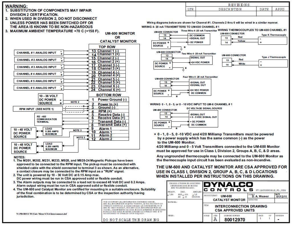
7 Terminal Connections All connections are made via the removable connectors on the back of the unit. PIN Description PIN Description 1 GND (Power Gnd) 13 Channel 1 (-) 2 VIN (10-36 VDC input) 14 Channel 1 (+) 3 GND (mag pickup input) 15 Channel 2 (-) 4 RPM + (mag pickup input) 16 Channel 2 (+) 5 Receive Data (-) 17 Channel 3 (-) 6 Receive Data (+) 18 Channel 3 (+) 7 Transmit Data (-) 19 Channel 4 (-) 8 Transmit Data (+) 20 Channel 4 (+) 9 Alarm 1 21 Channel 5 (-) 10 Alarm 1 22 Channel 5 (+) 11 Alarm 2 23 Channel 6 (-) 12 Alarm 2 24 Channel 6 (+) Also used for USB download cable assembly p/n 270A (see page 16) Terminal screws to be tightened to 4 inch-pounds torque. See page 21 for complete wiring information. 6
8 Outline Dimensions 7
9 Programming Overview All programming is accomplished through the front keypad. Below is a brief description of each key. Press to enter or exit the configuration screens Press to enter or accept values Select up Select down Go back one screen Select and advance to next screen Initial configuration consists of the following steps: 1) Setting current date / time 2) Enabling each input 3) Defining each input type 4) Defining min. & max. display values for any current or voltage inputs 5) Defining measurement display units (PSI, mv, F, C, H20, etc) 6) Setting over / under setpoint trips 7) Selecting either output 1 or output 2 (or both) for alarm trips 8) Setting either latching or non-latching for output trips 9) Defining data logging events 8
10 Programming Instructions Important: The Catalyst Monitor must first be programmed prior to operation. When initially powering up the unit, the display will first indicate the firmware version and then go to the operational mode. It may also display a screen warning that the time & date need to be entered. This will be explained below. To configure the Catalyst Monitor, first go to the main programming screen by pressing the Menu / Escape key: The following menu icons will appear from left to right: Run Signal - defines run status input type (if any) Channel - enables each channel type and alarm thresholds Calibration - defines zero & span values for DCV & ma inputs Alarm Settings - for setting high /low alarm thresholds Alarm Logs - allows the user to view alarm status Communication - Log Reader / Modbus setup Data Logging - allows configuration of up to (10) different logging events System - allows EPA enable & current date / time settings 9
11 A description of each menu item follows: Run Signal There are (3) run types available. The definitions are as follows: None: No run indication required. Monitoring is always active. RPM: Monitoring is active when signal received from magnetic pickup. Digital: Monitoring is active when contact closure (connection to ground) is sensed. To select run signal type, use the up / down arrows to select, then press the right arrow to accept and advance to the next screen. If None is selected, there is no other action required other than to select escape. After selecting escape, you will be asked to select yes to save. If RPM is selected, you will need to set the # gear teeth, RPM threshold and startup delay. The RPM threshold is the speed above which monitoring will be active. The startup delay can be configured to delay monitoring if desired, allowing time for all inputs to be at normal levels. If no delay is required, set to 0 seconds. The magnetic pickup input terminals are indicated on page 5. If Digital is selected, you will only need to set the startup delay (if applicable). In this mode, a run signal will be sensed with a contact closure (or short) between the magnetic pickup input terminals indicated on page 5. Pressing at any time during configuration will prompt you to save the changes. Select Yes to save any changes made. Selecting No will not save changes. Channel Select the channel number to configure by pressing the up / down arrows, then pressing the right arrow to navigate and select the following: Enable Channel Channel Type Description Engineering Units Yes / No 0-1 V, 0-5 V, 0-10 V, 4-20 ma, J Type, K Type name input with up to 20 characters up to 3 characters, for example: PSI, mv, F, C etc Note: For thermocouple inputs, you must enter either F or C Differential calculations between channels 1&2, 3&4, 5&6 are also enabled by selecting the Channel icon. Enable Differential 1 for channels 1&2, Differential 2 for channels 3&4 and Differential 3 for channels 5&6. 10
12 Calibration Select the channel number to configure by pressing the up / down arrows and pressing the right arrow to select and continue. The screens allow you to define the Cal Zero and Cal Span values for any channels that are configured for 0-1 V, 0-5 V, 0-10 V or 4-20 ma inputs. Example A pressure transmitter is connected to channel # 1. The transmitter has a 4-20 ma output representing a pressure input of PSI. The Cal Zero and Cal Span values would be defined as: Cal Zero = 0 Cal Span = 500 Note that the Engineering Units would be input as PSI in Channel configuration above. Alarm Settings Select the channel number to configure by pressing the up / down arrows, then pressing the right arrow to navigate and select the following: Enable alarms Yes / No Alarm Type Latching / Non-Latching Alarm Output None / Output 1 / Output 2 / Output 1 and 2 Alarm Low threshold for under-trip Alarm High threshold for over-trip Alarm Reset Points Set Defaults / Set Manually If Set Manually is selected, 2 more screens follow: Alarm Reset Low manually set reset hysteresis for low trip Alarm Reset High manually set reset hysteresis for high trip Alarm Logs Selecting the Alarm Logs icon will allow you to view any active alarms as well as the history log for each channel. Select any channel number by pressing the up / down arrows. Then press the right arrow to view any active or logged alarms. Once an active alarm is acknowledged, it will be placed into the history log. The history log will continuously store the last 10 alarms for each channel as well as the time & date of each alarm occurrence. 11
13 Communication This allows configuration for downloading data and Modbus communications. Data Logging The setup for EPA required logging of the catalyst inlet temperature based on a 4-hour rolling average is described in the section named System on page 14. Additional data logging may be configured when you select the Data Logging icon. The Catalyst Monitor can be configured to log any of the parameters being monitored, at user defined time intervals. The values are saved to an internal flash memory with sufficient memory to hold up to 500,000 data values with date / time stamps. These values can be downloaded at any time to a PC using Dynalco s Log Reader software. The logging of any parameter is configured as an event. The Catalyst Monitor will allow up to (10) individual events to be defined. It s also possible to configure an event that will log the catalyst differential pressure at defined intervals. Note that some users may decide to manually record differential pressure once per month since this value needs to be recorded with engine fully loaded per RICE NESHAP. Example: To configure data logging of catalyst differential pressure after engine warm up: (Note that this configuration will require an input signal from a magnetic pickup to sense engine running.) Using the arrows on the keypad, select the Data Logging icon. Next, select Setup Log Events and press the The next screen will display a list of (10) events that can be configured. If this is the first event to be programmed, select Event 1 and press the Next select Enable and press the The next screen allows you to define an On condition. The configuration for logging the differential pressure will require an On condition defined by an engine run signal. See above (page 9) for the procedure for configuring the run signal. In this case, select Yes and press the Select Edit Compare on the next screen and press the Select Compare 1 on the next screen and press the Select RPM on the next screen and press the Select Greater Than on the next screen and press the 12
14 Select A Value on the next screen and press the On the following screen, select an RPM value that will indicate engine running. This value should be lower than the normal engine running speed and higher than the RPM defined as the run signal in page 9. The next screen will ask if you want to Edit Another? Select yes and press the Select Compare 2 on the next screen and press the Select RPM on the next screen and press the Select Less Than on the next screen and press the Select A Value on the next screen and press the On the following screen, select an RPM value that will indicate the engine stopping. This value should be lower than the RPM selected above. The next screen will ask if you want to Edit Another? Select no and press the Press the arrow (3) more times until the screen appears as Enter ON Delay. Enter this number as the time delay (in seconds) following engine start when you would like to log the catalyst differential pressure. The maximum value configurable is 3600 seconds (60 minutes.) After entering the time delay, press The next screen allows you to define an Off condition. Select Yes and press the Select Compare 2 on the next screen and press the The next screen will ask if you want to Edit Another? Select no and press the The next screen appears as Enter OFF Delay. Enter this number as the time delay (in seconds) following engine stop when you would like to stop logging data. The maximum value configurable is 3600 seconds (60 minutes) but this would normally be set to 0 seconds. After entering the time delay, press The next screen named Input To Log allows the user to select which parameter to log. Using the up / down arrows, select the input that is defined as the catalyst differential pressure. Press The next screen named Log Frequency allows the configuration of how often (in minutes) the value is to be logged. Entering 0 minutes will allow only (1) data log event following the start delay. If you wanted to continuously log the differential pressure, you would select the frequency in minutes between data logs. Selecting escape will return to the Log Frequency screen. Press the arrow and then select Yes to save the changes. 13
15 Pressing the escape key two times will escape to the normal monitoring mode. System Display defaults allows the selection of either single channel (absolute) or differential value display. Note that regardless of this setting, pressing the right or left arrow during normal operation will display the alternate display type. Digital output allows the configuration of the solid state relay alarm outputs as either Normally Open or Normally Closed EPA enable is used to enable a 4-hour rolling average calculation (RICE NESHAP requirement) of the catalyst inlet temperature. Select whichever channel is configured to monitor the catalyst inlet temperature. Once this is enabled, the inlet temperature will be displayed as a 4-hour rolling average value. Specifically, the instantaneous values will be averaged into 1-hour averages which will then be used to calculate the 4-hour average. The 4-hour average will also be continuously logged at 15 minute intervals as long as the monitor is receiving an engine run signal. If the engine does not run for a full 4 hours, then the averaged data from the previous engine run will be used to calculate the next run time. An example of the logging process is on page 18. Set date and time is self-explanatory but is important for proper date / time stamps for both alarm logs and data logging. IMPORTANT NOTICE REGARDING CORRECT DATE / TIME SETTING: The correct date / time is imperative for proper data logging. Please note that the date and time may need to be re-programmed if the Catalyst Monitor loses input power for over 1 week. This will be indicated by a warning upon powering up the unit. Note that only the date / time may be affected by extended loss of power. Any data logged to the internal flash memory will be held indefinitely. 14
16 Alarm Outputs The Catalyst Monitor will alarm when channel values or differential values are above or below limits as specified. Alarms can be configured as either latching or non-latching. If an alarm condition is met, the red LED on the front panel will blink and the digital output(s) will trip. The alarm point name (ch1, ch2, df1, df2) that caused the alarm will be stored in memory with date/time stamp info. Non-latching alarms will reset the alarm if its value returns to normal. Latching alarms require manual resetting via the front keypad. WARNING: The alarm / shutdown output should be tested monthly for proper operation, especially if being used for over temperature shutdown or other critical function. Catalyst Inlet Temperature Monitoring (per RICE NESHAP requirements) The Catalyst Monitor will allow you to configure any one channel to monitor the catalyst inlet temperature based on a 4 hour rolling average per the RICE NESHAP mandate. To set this up, first go to the main menu, then select System. Select EPA enable and then select which channel is monitoring the catalyst inlet temperature. Please note that once this is configured, the channel representing the catalyst inlet temperature will always display the 4 hour average, not instantaneous exhaust temperature. IMPORTANT NOTICE REGARDING POWER INTERRUPTION: If input power to the Catalyst Monitor is disconnected during a data log operation, there is the possibility of losing data (see page 2). To prevent this, it is important to turn off the data logging prior to power disconnect. This is accomplished through the Data Logging icon on the main menu. When this is selected, the first screen will allow you to select Stop Logging. Pressing the arrow will provide instructions for a safe power down. The data logging will be enabled automatically when power is re-applied. 15
 on the back of the Catalyst Monitor.")
17 Downloading logged values to PC using LogReader software The hardware connection from the Catalyst Monitor to a PC is via a USB cable assembly, Dynalco p/n 270A The 6 ft cable length allows easy connection via a 4 pin Phoenix plug to the lower connector (terminals 5, 6, 7, 8) on the back of the Catalyst Monitor. When initially plugging the download cable into the PC s USB port, the new device should be recognized and the driver installed automatically. Please call (954) if the driver is not installed properly or assistance is required. The Dynalco host software LogReader is available as a free download from our website: There are (2) versions available: LogReader Ver. 1 LogReader ver. 2 Use for Version 1 Catalyst Monitors Use for Version 2 Catalyst Monitors Following installation, you may click on the icon to open the application. This software will allow date selectable log values to be downloaded to an excel spread sheet on the PC. 16
 that may have been configured. An example of this download is below.")
18 There are (3) reports generated by the LogReader software: The report named CatalystDataLog is a spreadsheet of logged values as configured in the Data Logging module (see page 12). This report does not contain 4-hour averaged values but only other events (up to 10 events) that may have been configured. An example of this download is below. Note that in this example, the columns format was selected which lines up the various log events (5 events in this case) in separate columns. 17
.")

19 The 2 nd report named CatalystDataLogEPAInstant contains the instantaneous catalyst inlet temperatures taken at 15 minute intervals. Note that the input channel configured to monitor the inlet temperature must also be configured as the EPA Enabled channel (see page 14). There are (4) different events that are assigned to the EPA enabled channel; events 21, 22, 23 & 24. The (4) temperature values in each event ID are then used to calculate one-hour averages. Note that in some cases, an engine may be stopped before a full hour of data is collected. In this case, if there are at least (2) logged values, a 1-hour average will be calculated, per the EPA ruling. Finally, the (4) consecutive one-hour averages are used to calculate the EPA 4-hour rolling average. All values (instantaneous and averaged) will be seen in the 3 rd report described next. The 3 rd report named CatalystDataLogEPAHourly contains the same instantaneous values logged above plus the hourly averages and finally the four hour averages. 18
20 Modbus Communication The unit also provides access to the internal registered values using the Modbus Protocol. The diagram below shows the recommended connections to the removable connectors on the back of the unit for either half-duplex or full-duplex (RS485). Wiring is as follows: PIN Description 5 TD(A) ** 6 TD(B) ** 7 Jumper to PIN 5 8 Jumper to PIN 6 ** A 120 ohm termination resistor may need to be installed across pins 5 & 6. 19
21 Modbus Address Registers: The Modbus address registers are defined in the tables below. Input Register Table (table 1) Modicon Address Modbus Offset Description Min Value Max Value Data type Status Register, 0=not running, bit signed integer 1=running Reserved bit signed integer Alarms Bit mask Bit 0 - Channel 1 Alarm h Bit 1 - Channel 2 Alarm h Bit 2 - Channel 3 Alarm h Bit 3 - Channel 4 Alarm h Bit 4 - Channel 5 Alarm h Bit 5 - Channel 6 Alarm h Bit 6 - Channel 1-2 Differential h Alarm Bit 7 - Channel 3-4 Differential h Alarm Bit 8 - Channel 5-6 Differential h Alarm Bit 9 - reserved h Bit 10 - reserved h Bit 11 - reserved h Bit 12 - reserved h Bit 13 reserved h Bit 14 reserved h Bit 15 reserved h Channel 1 Value bit signed integer Channel 2 Value bit signed integer Channel 3 Value bit signed integer Channel 4 Value bit signed integer Channel 5 Value bit signed integer Channel 6 Value bit signed integer Channel 1 and 2 Differential Value bit signed integer Channel 3 and 4 Differential Value bit signed integer Channel 5 and 6 Differential Value bit signed integer Channel 1 High Alarm Limit bit signed integer Channel 2 High Alarm Limit bit signed integer Channel 3 High Alarm Limit bit signed integer Channel 4 High Alarm Limit bit signed integer 20
22 Channel 5 High Alarm Limit bit signed integer Channel 6 High Alarm Limit bit signed integer Channel 1 and 2 Differential High bit signed integer Alarm Limit Channel 3 and 4 Differential High bit signed integer Alarm Limit Channel 5 and 6 Differential High bit signed integer Alarm Limit Channel 1 Low Alarm Limit bit signed integer Channel 2 Low Alarm Limit bit signed integer Channel 3 Low Alarm Limit bit signed integer Channel 4 Low Alarm Limit bit signed integer Channel 5 Low Alarm Limit bit signed integer Channel 6 Low Alarm Limit bit signed integer Channel 1 and 2 Differential Low bit signed integer Alarm Limit Channel 3 and 4 Differential Low bit signed integer Alarm Limit Channel 5 and 6 Differential Low bit signed integer Alarm Limit RPM bit unsigned integer Register Table Version bit unsigned integer Log Buffer Entry #1 Custom (See table 4) Log Buffer Entry #2 Custom (See table 4) Log Buffer Entry #3 Custom (See table 4) Log Buffer Entry #4 Custom (See table 4) Log Buffer Entry #5 Custom (See table 4) Log Buffer Entry #6 Custom (See table 4) Log Buffer Entry #7 Custom (See table 4) Log Buffer Entry #8 Custom (See table 4) Log Buffer Entry #9 Custom (See table 4) Log Buffer Entry #10 Custom (See table 4) Log Buffer Entry #11 Custom (See table 4) 21
23 Log Buffer Entry #12 Custom (See table 4) Log Buffer Entry #13 Custom (See table 4) Log Buffer Entry #14 Custom (See table 4) Log Buffer Entry #15 Custom (See table 4) Log Buffer Entry #16 Custom (See table 4) Log Buffer Entry #17 Custom (See table 4) Log Buffer Entry #18 Custom (See table 4) Log Buffer Entry #19 Custom (See table 4) Log Buffer Entry #20 Custom (See table 4) Log Buffer Entry #21 Custom (See table 4) Log Buffer Entry #22 Custom (See table 4) Log Buffer Entry #23 Custom (See table 4) Log Buffer Entry #24 Custom (See table 4) Log Buffer Entry #25 Custom (See table 4) Log Buffer Entry #26 Custom (See table 4) Log Buffer Entry #27 Custom (See table 4) Log Buffer Entry #28 Custom (See table 4) Log Buffer Entry #29 Custom (See table 4) Log Buffer Entry #30 Custom (See table 4) Channel 1 Float Value bit Float(IEEE 754) Channel 2 Float Value bit Float(IEEE 754) 22
24 Channel 3 Float Value bit Float(IEEE 754) Channel 4 Float Value bit Float(IEEE 754) Channel 5 Float Value bit Float(IEEE 754) Channel 6 Float Value bit Float(IEEE 754) Channel 1 and 2 Differential Value bit Float(IEEE 754) Channel 3 and 4 Differential Value bit Float(IEEE 754) Channel 5 and 6 Differential Value bit Float(IEEE 754) Channel 1 High Alarm Limit bit Float(IEEE 754) Channel 2 High Alarm Limit bit Float(IEEE 754) Channel 3 High Alarm Limit bit Float(IEEE 754) Channel 4 High Alarm Limit bit Float(IEEE 754) Channel 5 High Alarm Limit bit Float(IEEE 754) Channel 6 High Alarm Limit bit Float(IEEE 754) Channel 1 and 2 Differential High Alarm Limit Channel 3 and 4 Differential High Alarm Limit Channel 5 and 6 Differential High Alarm Limit bit Float(IEEE 754) bit Float(IEEE 754) bit Float(IEEE 754) Channel 1 High Low Limit bit Float(IEEE 754) Channel 2 High Low Limit bit Float(IEEE 754) Channel 3 High Low Limit bit Float(IEEE 754) Channel 4 High Low Limit bit Float(IEEE 754) Channel 5 High Low Limit bit Float(IEEE 754) 23
 Channel 1 and 2 Differential Low Alarm Limit Channel 3 and 4 Differential Low Alarm Limit Channel 5 and 6 Differential Low Alarm Limit -9999.0 99999.")
25 Channel 6 High Low Limit bit Float(IEEE 754) Channel 1 and 2 Differential Low Alarm Limit Channel 3 and 4 Differential Low Alarm Limit Channel 5 and 6 Differential Low Alarm Limit bit Float(IEEE 754) bit Float(IEEE 754) bit Float(IEEE 754) RPM bit unsigned integer Hourmeter bit unsigned integer 24
26 25
5450 NW 33rd Ave, Suite 104 Fort Lauderdale, FL Fruitland Ave Los Angeles, CA UM Channel Monitor.
 5450 NW 33rd Ave, Suite 104 Fort Lauderdale, FL 33309 3211 Fruitland Ave Los Angeles, CA 90058 UM-600 6-Channel Monitor Version 2 Installation and Operation Manual Rev. G P/N145F-12990 PCO 00007462 (c)
5450 NW 33rd Ave, Suite 104 Fort Lauderdale, FL Fruitland Ave Los Angeles, CA SST7000 SST7100. Speed Switch / Transmitter
 5450 NW 33rd Ave, Suite 104 Fort Lauderdale, FL 33309 3211 Fruitland Ave Los Angeles, CA 90058 SST7000 SST7100 Speed Switch / Transmitter Installation and Operation Manual Rev. C P/N145F-13112 PCO 00009270
3690 N.W. 53rd Street Fort Lauderdale, FL SC-2124 SC-2124M. 24 Channel Universal Scanner. Installation and Operation Manual P/N 145F-11902
 3690 N.W. 53rd Street Fort Lauderdale, FL 33309 SC-2124 SC-2124M 24 Channel Universal Scanner Installation and Operation Manual P/N 145F-11902 Rev. 3.30 (c) Copyright 2000, Dynalco Controls All Rights
INSTALLATION INSTRUCTIONS
 www.altroniccontrols.com INSTALLATION INSTRUCTIONS EXACTA 21 MONITORING AND CONTROL SYSTEM CAUTION: The EXACTA 21 CONTROL SYSTEM is CSA CERTIFIED FOR use in Class I, GROUPS C & D, Division 2 hazardous
Scanner 2000 microefm QuickStart. Installing the Scanner Remote Mount. Direct Mount NUFLO. Part No , Rev. A
 NUFLO Part No. 30165024, Rev. A Scanner 2000 microefm QuickStart Installing the Scanner 2000 H L H L Flow Direct Mount To install the Scanner 2000 microefm using a direct mount to an orifice or cone meter
Analyzer/Controller. ph/orp HART. Model 54e ph/orp ESSENTIAL INSTRUCTIONS WARNINGS RISK OF ELECTRICAL SHOCK
 Instruction Sheet PN 51A-54epH/rev J October 2010 ph/orp HART Model 54e ph/orp Analyzer/Controller For additional information, please visit our website at www.emersonprocess.com/raihome/liquid/. ESSENTIAL
Environmental Chamber Programmer/Controller
 Environmental Chamber Programmer/Controller Complete Single, Dual or Three Channel Control System. or - Patented FastTRAC Part Temperature Control. or FastTRAC Control Plus Second Channel for Vibration,
WARNING. TTDJ Series Fully-Configurable Fault Annunciator Installation and Operations Manual
 TTDJ Series Fully-Configurable Fault Annunciator Installation and Operations Manual TTDJ-99062N Revised 04-04 Section 50 (00-02-0412) Please read the following information before installing. This installation
MODCELL 2050R Single Loop Controllers
 Isolated universal process and remote set-point input Four internal set-points No jumpers required to define instrument parameters Ratio/bias on process and remote set-point Totalizer Ramp/soak profile
MODBUS RTU I/O Expansion Modules - Models C267, C277, and C287. Installation and Operations Manual Section 50
 MODBUS RTU I/O Expansion Modules - Models C267, C277, and C287 Installation and Operations Manual 00-02-0651 09-01-09 Section 50 In order to consistently bring you the highest quality, full featured products,
TTD Series Configurable Fault Annunciator. Installation and Operations Manual Section 50
 TTD Series Configurable Fault Annunciator Installation and Operations Manual 00-02-0697 2013-04-22 Section 50 In order to consistently bring you the highest quality, full featured products, we reserve
M2500 Engine Controller Configuration Manual
 M2500 Engine Controller Configuration Manual Revision: 08-04-2011 Page 1 Contents 1 Preface... 4 2 Configuration from front panel... 5 2.1 Engine Controller Configuration... 6 2.1.1 RPM settings... 6 2.1.2
Installation and Operating Instructions
 Installation and Operating Instructions Modbus Terminal Board Form MTB IOI 4-12 1.0 DESCRIPTION 1.1 The Modbus Terminal Board is an RS-485, MODBUS RTU slave board capable of reading 33 channels. The first
Analyzer/Sensor to measure UV Spectral Absorbance
 Quick Start-up Guide Integra OUM960/ OUSAF44 Analyzer/Sensor to measure UV Spectral Absorbance This guide is intended to provide quick guidance and help to perform a basic instrument start-up. For detailed
INSTALLATION INSTRUCTIONS
 www.altronicinc.com INSTALLATION INSTRUCTIONS DEVIATION FROM THESE INSTRUCTIONS MAY LEAD TO IMPROPER OPERATION OF THE MACHINE WHICH COULD WARNING: CAUSE PERSONAL INJURY TO OPERATORS OR OTHER NEARBY PERSONNEL.
ALTRONIC LOOP CONTROLLER INSTALLATION & OPERATING MANUAL MODEL DE-1500 FORM DE-1500 IOI 8-03
 ALTRONIC LOOP CONTROLLER INSTALLATION & OPERATING MANUAL MODEL DE-1500 FORM DE-1500 IOI 8-03 WARNING: DEVIATION FROM THESE OPERATING INSTRUCTIONS MAY LEAD TO IMPROPER ENGINE/MACHINE OPERATION WHICH COULD
PF2100 MODBUS LOGGER CARD SYSTEM SPECIFICATION. v1.0 DRAFT Revised Dec 4, 2014 Last Revised by Alex Messner
 PF2100 MODBUS LOGGER CARD SYSTEM SPECIFICATION Revised Last Revised by Alex Messner This page was intentionally left blank. Table of Contents 1 Overview... 2 2 User Interface... 3 2.1 LEDs... 3 2.2 Buttons...
CDD4 Duct Carbon Dioxide Transmitter
 Drill or punch a 1-1/8 or 1-1/4 hole in the duct at the preferred location and insert the probe into the hole to mark the enclosure mounting holes. Remove the unit and drill the four mounting holes. Clean
IPM650 Intelligent Panel-Mount Display
 Quick Start Guide IPM650 Intelligent Panel-Mount Display Sensor Solutions Source Load Torque Pressure Multi Component Calibration Instruments Software www.futek.com Getting Help TECHNICAL SUPPORT For more
Automationdirect.com. D i r e c t L o g i c M a g n e t i c P u l s e I n p u t C o p r o c e s s o r F 4-8 M P I
 Automationdirect.com D i r e c t L o g i c 0 5 M a g n e t i c P u l s e I n p u t C o p r o c e s s o r F - 8 M P I Manual Order Number: F-8MPI-M TRADEMARKS AutomationDirect.com is a Trademark of Automationdirect.com
DE SERIES. Enhanced DE-2500 System Now Available. Programmable Safety Shutdown, Monitoring and Control Products with Analog Input Capabilities
 Enhanced DE-2500 System Now Available DE SERIES Programmable Safety Shutdown, Monitoring and Control Products with Analog Input Capabilities A state-of-the-art family of products specifically designed
Rhino Buffer Module PSM24-BFM600S. Operating Instructions
 Rhino Buffer Module PSM24-BFM600S Operating Instructions RHINO BUFFER MODULE PSM24-BFM600S Description The PSM24-BFM600S Buffer Module will hold the output voltage of a 24 VDC power supply after brownouts
INSTALLATION INSTRUCTIONS MBPEFY Series Mixing Box for Mitsubishi PEFY Series Units. Before Starting Installation Warning. Installation Instructions
 Before Starting Installation Warning Shut power to unit prior to any work being done. Personal injury or death could result. Only qualified HVAC service personnel should install, troubleshoot, repair or
Plus-X 300. Installation and Operation Manual
 Plus-X 300 Installation and Operation Manual Table of Contents Introduction... 1 Compatibility... 1 Installation... 1 Configuration... 2 Operation... 5 Getting Help... 6 Warranty... 6 Appendix A: Specifications...
LAUREL. Laureate Dual-Channel Pulse Input Totalizer With Two Independently Scalable Input Channels & Presets ELECTRONICS, INC. Features.
 Description LAUREL ELECTRONICS, INC. Laureate Dual-Channel Pulse Input Totalizer With Two Independently Scalable Input Channels & Presets Features Frequencies up to 1 MHz Totals stored in non-volatile
TTD Series Configurable Fault Annunciator. Installation and Operations Manual Section 50
 TTD Series Configurable Fault Annunciator Installation and Operations Manual 00-02-0697 2016-08-08 Section 50 In order to consistently bring you the highest quality, full-featured products, we reserve
Table of Contents. General Information. Document Sure-Aire Flow Monitoring System. User and Service Manual WARNING CAUTION
 Document 476092 User and Service Manual Installation, Operation and Maintenance Manual Please read and save these instructions for future reference. Read carefully before attempting to assemble, install,
TC Type Range Conformity Error. J -210 C to +760 C (-347 F to F) ±0.09 C (±0.16 F) K -244 C to C (-408 F to F) ±0.1 C (±0.
 ±0.09 C (±0.16 F) K -244 C to C (-408 F to F) ±0.1 C (±0.") LAUREL ELECTRONICS, INC. Laureate Thermocouple Panel Meter / Controller Features Factory calibrated for thermocouple types J, K, T, E, N, R, S Entire range of each thermocouple in one scale Highly accurate
LAUREL ELECTRONICS, INC. Laureate Thermocouple Panel Meter / Controller Features Factory calibrated for thermocouple types J, K, T, E, N, R, S Entire range of each thermocouple in one scale Highly accurate
EMS467 Monitoring System. Installation and Operations Manual Section 40
 EMS467 Monitoring System Installation and Operations Manual 00-02-0672 01-26-10 Section 40 In order to consistently bring you the highest quality, full featured products, we reserve the right to change
M A C 3 Wind Speed Alarm & Controller
 M A C 3 Wind Speed Alarm & Controller Installation Instructions Thank you for purchasing the MAC3 wind speed alarm and controller. This manual is designed to lead you through a step-by-step process to
Operating Manual IN-LINE ENGINE CONTROL SYSTEM. Form GPN1000 OM 11-12
 Operating Manual IN-LINE ENGINE CONTROL SYSTEM Form GPN1000 OM 11-12 1.0 OVERVIEW 1.1 This manual applies to GPN1000 and GPN1000-12 panels used with Series 25-A, 50-A, 65-A, and 65-B (formerly Series A-A,
MPI-DN, MPI-D MULTICHANNEL ELECTRONIC RECORDER for HART or RS-485/ MODBUS RTU SENSORS
 MPI-DN, MPI-D MULTICHANNEL ELECTRONIC RECORDER for HART or RS-485/ MODBUS RTU SENSORS 18 channels for HART / Modbus RTU sensors 2 digital channels 16 math channels 4 relay outputs for alarm or control
Installation and Operating Manual FM50 IOM 2-18 DRAFT
 Installation and Operating Manual Table of Contents 1. Safety Precautions... 3 2. Details 2.1 Part Numbers... 4 2.2 Configurations... 5 2.3 Specifications... 13 2.4 Cables and Wiring... 14 2.5 Interface,
Click Save to return to the main Setup screen.
 ON-SITE Setup Guide Thank you for purchasing the ON-SITE. This guide will assist you in the setup of the system. You can call for FREE technical support to get help anytime at 757-258-0910. Please note,
CDD Carbon Dioxide Transmitter
 Introduction The OSA CO2 transmitter uses Infrared Technology to monitor CO2 levels within a range of 0 2000 ppm and outputs a linear 4-20 ma or 0-5/0-10 Vdc signal. The enclosure is designed to operate
R7X CONFIGURATOR. (model: R7CON) Users Manual , Minamitsumori, Nishinari-ku, Osaka JAPAN Tel: Fax:
 Users Manual , Minamitsumori, Nishinari-ku, Osaka JAPAN Tel: Fax:") R7X CONFIGURATOR (model: R7CON) Users Manual 5-2-55, Minamitsumori, Nishinari-ku, Osaka 557-0063 JAPAN Tel: +81-6-6659-8201 Fax: +81-6-6659-8510 http://www.m-system.co.jp/ E-mail: info@m-system.co.jp R7CON
R7X CONFIGURATOR (model: R7CON) Users Manual 5-2-55, Minamitsumori, Nishinari-ku, Osaka 557-0063 JAPAN Tel: +81-6-6659-8201 Fax: +81-6-6659-8510 http://www.m-system.co.jp/ E-mail: info@m-system.co.jp R7CON
SI3300. user and installation manual. 4-20mA/DC-Digital Display
 SI3300 4-20mA/DC-Digital Display The SI3300 is a member of the SI3000 Readout Family. All members of the family are marked SI3000 on the front panel. This manual is specifically for the SI3300 Model with
MAC3 Wind Speed Alarm & Controller. Installation Instructions
 MAC3 Wind Speed Alarm & Controller Installation Instructions Table of Contents Overview... 3 Installation... 3 Optional Equipment... 10 Dual Sensor Operation... 10 Other Optional Equipment... 10 Operation
CRAGG RAILCHARGER Instruction Manual for 10DTC-12V 20DTC-12V 30DTC-24V 40DTC-12V 60DTC-12V
 CRAGG RAILCHARGER for 10DTC-12V 20DTC-12V 30DTC-24V 40DTC-12V 60DTC-12V Contents 1 Warnings, Cautions, and Notes... 1 2 Description... 2 3 Features... 2 3.1 STANDARD FEATURES... 2 3.2 CHARGER REGULATION...
OZONE SWITCH Model OS-6. OS-6 Features
 USER MANUAL OZONE SWITCH Model OS-6 OS-6 Features The OS-6 is an industrial grade ozone controller and monitor. The OS-6 design is optimized for accuracy and ease of installation, setup and operation.
MTII4200 Level Transmitter Installation, Operation & Maintenance Instructions
 Specialists in Liquid Level Indication MTII4200 Level Transmitter Installation, Operation & Maintenance Instructions Section: M500 Bulletin: M500.31 Date: 05-17-16 Supersedes: 09-30-11 1. INTRODUCTION
LAUREL. Laureate RTD Temperature Panel Meter / Controller ELECTRONICS, INC. Features. Description. Specifications
 LAUREL ELECTRONICS, INC. Laureate RTD Temperature Panel Meter / Controller Features Factory calibrated for 100Ω platinum, 10Ω copper & 120Ω nickel RTDs 2, 3 or 4-wire connection with lead resistance compensation
REDUNDANCY MODULE TSP-REM360 AND TSP-REM600
 REDUNDANCY MODULE TSP-REM360 AND TSP-REM600 Operating Instructions Seite 1 Dimensions drawings: TSP-REM360 Weight: 0.882lb Gewicht: 0.40kg Seite 2 Dimensions drawings: TSP-REM600 Bottom view Top view Side
SP6R Level Controller Operation Manual
 SP6R Level Controller Operation Manual www.sjerhombus.com SP6R LEVEL CONTROLLER INTRODUCTION SJE-Rhombus, an industry leader in water and wastewater pump controls, introduces the SP6R Level Controller.
PROFIRE 3100 User Interface Assembly
 PF3100 User Interface Assembly Product Manual April 2018 Rev. 2.1 3100 User Interface Assembly The User Interface (UI) Assembly is designed to provide easy interface between operators and the BMS controller.
Flomatic Smart Card TM Model FDHC-100 (Digital High-Resolution Controller) Configuration and Operation Manual
 Configuration and Operation Manual") The Flomatic FDHC-100 is a high performance Digital positioner intended to control AC actuators, providing 450 points of resolution with quarter turn actuators ranging from 2 sec to 120 sec and rated for
The Flomatic FDHC-100 is a high performance Digital positioner intended to control AC actuators, providing 450 points of resolution with quarter turn actuators ranging from 2 sec to 120 sec and rated for
+GF+ SIGNET ph/orp Transmitter Instructions
 GF SIGNET 8750 ph/orp Transmitter Instructions ENGLISH 8750.090 A9/99 English CAUTION! Remove power to unit before wiring input and output connections. Follow instructions carefully to avoid personal injury.
ProScale LCD Readout Quick Start Guide
 ProScale LCD Readout Quick Start Guide This Guide includes basic operation instructions for 950, General Purpose, Basic & In-Panel LCD Readouts For the Complete OPERATION Manual go to www.proscale.com/manuals.htm
JT400 Multivariable Transmitter
 Product Specification Sheet JT400 Multivariable Transmitter Wireless Ultra Low Power Platform with Integrated, Chart Replacement Data Logging and I/O The industry s first, ultra-low power, multivariable
MODEL DE-2000 FORM DE OI 9-01
 ALTRONIC ANNUNCIATOR SYSTEM OPERATING INSTRUCTIONS MODEL DE-2000 FORM DE OI 9-01 WARNING: DEVIATION FROM THESE OPERATING INSTRUCTIONS MAY LEAD TO IMPROPER ENGINE OPERATION WHICH COULD CAUSE PERSONAL INJURY
Flex Series User Guide
 User Programmable Current 4..20mA Digital RS485 Dual & Single Axis Up to 360º 2016 Flex Series User Guide Sensor Installation, Wiring, Flexware App Instructions Page 1 of 33 Page 2 of 33 Table of Contents
LAUREL. Laureate Pulse or Analog Input Batch Controller Automatic batch control for repetitive liquid fill operations ELECTRONICS, INC.
 Description LAUREL ELECTRONICS, INC. Laureate Pulse or Analog Input Batch Controller Automatic batch control for repetitive liquid fill operations Features Available for turbine flow meter pulse signals
Model No Universal Input Indicator Start-up Guide
 Model No. 1480 Universal Input Indicator Start-up Guide Contents 1. Setting up a unit straight out of the box... 3 1.1. Entry into Configuration mode... 3 1.2. Scrolling through Parameters and s... 3 1.3.
2 Table of Contents 1. TABLE OF CONTENTS. 1. Table of Contents Introduction Wiring Diagram Terminals Review...
 TPR-6 Temperature Protection Relay Instruction Manual Ver. June 1 st 2010 2 Table of Contents 1. TABLE OF CONTENTS 1. Table of Contents... 2 2. Introduction... 3 3. Wiring Diagram... 5 4. Terminals Review...
MODEL: R1M-P4. PC Recorders R1M Series. SPECIFICATIONS OF OPTION: Q COATING (For the detail, refer to M-System's web site.)
") PC Recorders Series PC RECORDER (4 totalized counter inputs, 8 contact inputs and outputs) Functions & Features Industrial recorder on PC Totalized counter inputs Counts stored in E 2 PROM Easy system
PC Recorders Series PC RECORDER (4 totalized counter inputs, 8 contact inputs and outputs) Functions & Features Industrial recorder on PC Totalized counter inputs Counts stored in E 2 PROM Easy system
IPM500 Series QuickStart Manual
 IPM500 Series QuickStart Manual The Force of Innovation 10 Thomas Irvine, CA 92618 USA (949) 465-0900 FAX: (949) 465-0905 E-Mail: HTUfutek@futek.comUTH www.futek.com Manufacturer of Load Cells, Pressure
LAUREL. Laureate Digital Panel Meter for Process and Ratiometric Signals ELECTRONICS, INC. Features. Description
 LAUREL ELECTRONICS, INC. Laureate Digital Panel Meter for Process and Ratiometric Signals Features Reads process signals from ±200 mv to ±600V or ±2 ma to ±5A full scale Ratiometric mode for bridges and
ABB Drives. User s Manual. Modbus Adapter Module RMBA-01
 ABB Drives User s Manual Modbus Adapter Module RMBA-01 Modbus Adapter Module RMBA-01 User s Manual 3AFE 64498851 REV A EN EFFECTIVE: 1.3.2002 2002 ABB Oy. All Rights Reserved. Safety instructions Overview
TOXALERT MODEL AIR 2000
 TOXALERT MODEL AIR 2000 NOTE: Toxalert s Model GVU-CO 2 Sensor is the same as the Air2000R. Microprocessor-based, Infrared Environmental CO 2 Sensor OPERATOR S MANUAL TOXALERT TM INTERNATIONAL INC. P.O.
INDEX. Analog Board Boot and Voltage Test 2 Testing Input Channels 3 Testing Output Channels 4
 INDEX Analog Board Boot and Voltage Test 2 Testing Input Channels 3 Testing Output Channels 4 Digital Board Boot and Voltage Test 5 Testing Input Channels 6 Testing Output Channels 7 Display Testing 8
Quick Start Guide MC-III TM Flow Analyzer
 Quick Start Guide MC-III TM Flow Analyzer A Quick Reference on Mounting, Wiring, & Configuring the MC-III EXP or WP Flow Analyzer For complete instructions, see MC-III EXP User Manual, Part No. 9A-50165003
2-Axis Counter BDD 622
 2-Axis Counter BDD 622 Technical Description, User's Guide english No. 622-221 D/E. Edition 0701; Subject to modification. www.balluff.com Balluff GmbH Schurwaldstrasse 9 73765 Neuhausen a.d.f. Germany
1.6. Counters, Panel Meters, Tachometers and Timers. Contents Description Fusion Integrated Machine Control Standards and Certifications...
 .6 Contents Standards and Certifications............... Product Selection....................... Technical Data and Specifications........... Dimensions............................ Learn Online Page V3-T-04
WARNING: Do not use the thermometer/data logger before you read the users manual and the following instructions.
 55 This unit passes the following tests EN 61326-1:2006 (CISPR11,IEC/EN 61000-3-2:2006, IEC/EN 61000-3-3: 1995+A1 :2001+A2:2005 IEC/EN 61000-4-2/-3/-5/-6/-11) WARNING: Do not use the thermometer/data logger
Docking Station DS-U4WEB with web server version 1 Instruction Manual
 Page 1 of 15 Docking Station DS-U4WEB with web server version 1 Page 2 of 15 Table of contents 1 Overview... 3 2 Description... 3 2.1 Connector identification... 3 2.2 Probe inputs... 4 2.3 Logical inputs
CDD4 Series Room CO2 Transmitter Installation Instructions
 CDD4 Series Room CO2 Transmitter Installation Instructions Introduction The CO2 transmitter uses Infrared Technology to monitor CO2 levels and outputs a linear 4-20 ma or 0-5/0-10 Vdc signal. Options include
MODEL KP-100 ACCESS CONTROL DIGITAL KEYPAD OPERATING INSTRUCTIONS
 MODEL KP-100 ACCESS CONTROL DIGITAL KEYPAD OPERATING INSTRUCTIONS Model KP-100 is a self-contained digital keypad. This keypad is suitable for residential, industrial, and commercial installations. It
Model 620A Maintenance and Calibration
 Model 0A Maintenance and Calibration CAUTION! See Ch Pg, A & B below prior to connecting inputs to TB of the A PCB. Determine Rev. of the A board on the Model 0/0A for correct input connections. Failure
MobilControl MC 4000 OWNER S MANUAL
 MobilControl MC 4000 Hand Held Service instrument with data logger for pressure, min / max & differential pressure, temperature, flow / rpm and hydraulic horsepower OWNER S MANUAL 20 7 TERMINALS 7.1 Plugs
ALTRONIC DIGITAL TEMPERATURE SCANNER INSTALLATION INSTRUCTIONS DSM-43820DUS FORM DSM43820 II 7-02
 ALTRONIC DIGITAL TEMPERATURE SCANNER INSTALLATION INSTRUCTIONS DSM-43820DUS FORM DSM43820 II 7-02 CAUTION: The DSM-43820DUS temperature scanner is suitable for use in Class I, Groups C & D, Division 1
TELEDYNE HASTINGS INSTRUMENTS
 TELEDYNE HASTINGS INSTRUMENTS INSTRUCTION MANUAL MASS FLOWMETER CONTROLLER READOUT POWERPOD-100 Manual Print History The print history shown below lists the printing dates of all revisions and addenda
UDC 1000 and UDC 1500 MICRO-PRO SERIES UNIVERSAL DIGITAL CONTROLLERS
 UDC 1000 and UDC 1500 MICRO-PRO SERIES UNIVERSAL DIGITAL CONTROLLERS EN0I-6041 12/99 PRODUCT SPECIFICATION SHEET OVERVIEW The UDC 1000 and UDC 1500 are microprocessor-based 1/16 DIN and 1/8 DIN controllers
INSTRUCTION MANUAL STATION CONTROLLER SC1000 MOTOR PROTECTION ELECTRONICS, INC.
 INSTRUCTION MANUAL STATION CONTROLLER SC1000 MOTOR PROTECTION ELECTRONICS, INC. 2464 Vulcan Road, Apopka, Florida 32703 Phone: (407) 299-3825 Fax: (407) 294-9435 Revision Date: 9-11-08 Applications: Simplex,
ARA FTS Flow Calibrator. Operation Manual August 1, 2016
 ARA FTS Flow Calibrator Operation Manual August 1, 2016 TABLE OF CONTENTS SECTION PAGE 1. INTRODUCTION 1 2. GETTING STARTED 1 2.1. Navigation 1 2.2. Charge Battery 1 2.3. Set Date and Time 2 2.4. Plug-In
INSTRUCTION MANUAL MODEL 8081 DIGITAL RECORDER
 INSTRUCTION MANUAL MODEL 8081 DIGITAL RECORDER Revision B February 2013 P/N 8081-0005 S/N 2001 N. Indianwood Ave., Broken Arrow, Oklahoma 74012 Tel: 918-250-7200 Telefax: 918-459-0165 E-mail: Chandler.sales@ametek.com
CENTURION Configurable Controller. Installation and Operations Manual Section 50
 CENTURION Configurable Controller Installation and Operations Manual 00-02-0590 10-10-06 Section 50 In order to consistently bring you the highest quality, full featured products, we reserve the right
Trident and Trident X2 Digital Process and Temperature Panel Meter
 Sign In New User ISO 9001:2008 Certified Quality System Home Products Online Tools Videos Downloads About Us Store Contact Policies Trident and Trident X2 Digital Process and Temperature Panel Meter Products
Connecting a Cisco Input Module
 CHAPTER 4 Overview The optional Cisco Input Module (Figure 4-1) is attached to a Cisco Physical Access Gateway or Cisco Reader Module to provide additional connections for up to ten input devices. Each
AMCI NX3A1E Specifications Rev 0.0 Resolver PLS Ethernet Module
 Module Overview The AMCI NX3A1E module is a single resolver input programmable limit switch module that is programmed by and communicates on Ethernet. The functionality of the NX3A1E is similar to the
Connecting a Cisco Output Module
 CHAPTER 5 Overview The optional Cisco Output Module (Figure 5-1) is attached to a Cisco Physical Access Gateway or Cisco Reader Module to provide additional connections for up to 8 outputs, each of which
XL7 OCS Datasheet for HE-XW1E0, HE-XW1E2, HE-XW1E3, HE-XW1E4, HE-XW1E5 HEXT391C100, HEXT391C112, HEXT391C113, HEXT391C114, HEXT391C115
 XL7 OCS Datasheet for HE-XW1E0, HE-XW1E2, HE-XW1E3, HE-XW1E4, HE-XW1E5 HEXT391C100, HEXT391C112, HEXT391C113, HEXT391C114, HEXT391C115 Specifications/Installation 1. Specifications General Specifications
PF 3100 BMS CARD PRO.FIRE
 PF 3100 BMS www.profireenergy.com 1.855.PRO.FIRE 1 TABLE OF CONTENTS PF3100 BMS INFORMATION GUIDE INTRODUCTION... 2 1.1 Functional Description.... 2 1.2 System Requirements.... 2 HARDWARE.... 3 2.1 Card
From lab to production, providing a window into the process. Dynisco's ATC990 and UPR900 Applications and Setup
 From lab to production, providing a window into the process Dynisco's ATC990 and UPR900 Applications and Setup Introduction UPR900 Indicator Is ¼ Din (96x96mm) size, 117mm depth behind the panel. It has
SINGLE-CHANNEL PROCESS CONTROLLERS & TEMP. DISPLAYS D3820/D3830 Series
 The Digitec Series D3800 Panel Meters offer many features and performance capabilities to suit a wide range of industrial applications. The D3820 and D3830 are available in the ranges of 4-20mA, 0-10 VDC,
AEROTRAK PORTABLE AIRBORNE PARTICLE COUNTER MODEL 9310/9350/9510/9550/9500 QUICK START GUIDE
 AEROTRAK PORTABLE AIRBORNE PARTICLE COUNTER MODEL 9310/9350/9510/9550/9500 QUICK START GUIDE Thank you for purchasing a TSI AeroTrak Portable Airborne Particle Counter (particle counter). This guide will
Eco Sensors OZONE CONTROLLER Model OS-6 Instructions for Use. General and New Features
 Eco Sensors OZONE CONTROLLER Model OS-6 Instructions for Use General and New Features The OS-6 is an industrial grade Ozone controller and monitor. The OS-6 design has been optimized for accuracy, ease
WARNING!!!!!!!!! IMPORTANT INFORMATION: READ BEFORE INSTALLATION!
 V_Net Relay Module Installation Instructions: Part Number: 230-VM-RELAY WARNING!!!!!!!!! IMPORTANT INFORMATION: READ BEFORE INSTALLATION! The relay outputs of the 230-VM-RELAY module may turn on when not
QUICK START. Installation & Programming Guide
 QUICK START Installation & Programming Guide PRECAUTIONS READ AND FOLLOW ALL SAFETY INSTRUCTIONS. CAUTION - RISK OF ELECTRICAL SHOCK. To prevent electrical shock, turn off power at the circuit breaker
+GF+ SIGNET Conductivity/Resistivity Transmitter Instructions
 GF SIGNET 8850 Conductivity/Resistivity Transmitter Instructions ENGLISH 8850.090 A9/99 English CAUTION! Remove power to unit before wiring input and output connections. Follow instructions carefully to
NT PRESSURE TRANSDUCER MODELS 4100, 4210, 4130, 4230
 P/N 0-027289 (Rev. A 04/4) NT PRESSURE TRANSDUCER MODELS 400, 420, 430, 4230 User Guide Table of Contents Safety Alert Symbol... 2 Introduction... 3 Installation... 3 Mechanical Installation... 3 Electrical
Portable Multi-Function Calibrator Model CEP6000
 Calibration Technology Portable Multi-Function Calibrator Model CEP6000 WIKA Data Sheet CT 83.01 Applications Calibration service companies/service industry Instrument and control workshops Industry (Laboratories,
Scanner 2000 Steam Mass Flow Transmitter
 3352051/2 IM-P335-24 MI Issue 2 Scanner 2000 Steam Mass Flow Transmitter Installation and Maintenance Instructions 1. Safety information 2. Mechanical installation 3. Configuring software 4. Wiring procedures
LAUREL. Laureate Rate Meter & Totalizer with Functions A+B, A-B, AxB, A/B, A/B-1 ELECTRONICS, INC. Features. Description
 Description LAUREL ELECTRONICS, INC. Features Laureate Rate Meter & Totalizer with Functions A+B, A-B, AxB, A/B, A/B-1 Arithmetic functions A+B, A-B, AxB, A/B, A/B-1 applied to rate or total for channels
ICN Mini Link/External. User s Guide. 1733N Model A Mini Link/EXT (Version 1) 1732N Model A ICN Interface Board (Version 1)
 1732N Model A ICN Interface Board (Version 1)") ICN Mini Link/External User s Guide 1733N Model A Mini Link/EXT (Version 1) 1732N Model A ICN Interface Board (Version 1) MicroMod Automation, Inc. The Company MicroMod Automation is dedicated to improving
ICN Mini Link/External User s Guide 1733N Model A Mini Link/EXT (Version 1) 1732N Model A ICN Interface Board (Version 1) MicroMod Automation, Inc. The Company MicroMod Automation is dedicated to improving
ACT-1B Series Panel Tachometer
 MONARCH INSTRUMENT Instruction Manual ACT-1B Series Panel Tachometer Printed in the U.S.A. Copyright 2009 Monarch Instrument, all rights reserved 1071-4843-111R 0909 15 Columbia Drive Amherst, NH 03031
D115 The Fast Optimal Servo Amplifier For Brush, Brushless, Voice Coil Servo Motors
 D115 The Fast Optimal Servo Amplifier For Brush, Brushless, Voice Coil Servo Motors Ron Boe 5/15/2014 This user guide details the servo drives capabilities and physical interfaces. Users will be able to
Installation & Operation
 LED Readout Installation & Operation WARRANTY Accurate Technology, Inc. warrants the ProScale Systems against defective parts and workmanship for 1 year commencing from the date of original purchase. Upon
Contents 1 Warnings, Cautions, and Notes Description Features... 1
 EnCell Contents 1 Warnings, Cautions, and Notes... 1 2 Description... 1 3 Features... 1 3.1 STANDARD FEATURES... 1 3.2 FRONT PANEL FEATURES... 2 3.2.1 Display... 2 3.2.2 OK LED... 2 3.2.3 FAULT LED...
Installation Instructions
 Installation Instructions DSM-4688DUS, DSM-4689DUS Digital Signal Monitors Form DSM4600 II 11-12 1.0 DESCRIPTION 1.1 The Altronic DSM-4600 series of digital monitors are electronic instruments designed
ALTERNATING RELAYS & CONTROLLERS ARM Series
 ALTERNATING RELAYS & CONTROLLERS ARM Series Process Control Equipment for Hazardous Locations 7M26 UL913 INCLUDES INTRINSICALLY SAFE INPUTS Integrated Duplex Controller SOSO Operation (Sequence-on, Simultaneous-off)