BLD04A Brushless DC Motor Driver
|
|
|
- Shon Lawson
- 5 years ago
- Views:
Transcription


1 BLD04A Brushless DC Motor Driver User s Manual V1.1 MAY 2011 Information contained in this publication regarding device applications and the like is intended through suggestion only and may be superseded by updates. It is your responsibility to ensure that your application meets with your specifications. No representation or warranty is given and no liability is assumed by Cytron Technologies Incorporated with respect to the accuracy or use of such information or infringement of patents or other intellectual property rights arising from such use or otherwise. Use of Cytron Technologies s products as critical components in life support systems is not authorized except with express written approval by Cytron Technologies. No licenses are conveyed, implicitly or otherwise, under any intellectual property rights.
2 Index 1. Introduction 3 2. Packing List 4 3. Product Specification and Limitations 5 4. Board Layout 6 5. Installation and Getting Started Setting Speed Control Mode (Open/Closed loop) UART Communication Protocol Using BLD04A with AR40B/IFC-BL Using BLD04A with microcontroller (Parallel Mode) Using BLD04A with microcontroller (UART Mode) Using BLD04A with PC (UART Mode) Warranty 30 Created by Cytron Technologies Sdn. Bhd. All Rights Reserved
3 1. INTRODUCTION BLD04A is designed to drive the Linix 10W and 30W brushless dc (BLDC) motor. It offers several enhancements over the original Linix BLDC motor driver such as closed loop speed control, UART interface and better protection for both the motor as well as the driver. Besides that, the interface of BLD04A is compatible with the original Linix BLDC motor driver and this makes the upgrading for existing users an effortless process. This BLDC motor driver is designed with the capabilities and features as below: Powered by high performance dspic Digital Signal Controller. Operating at DC +24V ±15%. Support up to 4A per phase. 4-Quadrant control. 5V logic level input for Start/Stop, Run/Brake, Direction and Alarm Reset. Support analog voltage (0 5V) or PWM signal for speed control. Support UART interface. Selectable open loop or closed loop speed control. The default mode is Open Loop mode. Current limiter. 12 pulses per revolution encoder output. Alarm indicator for overvoltage, undervoltage, out-of-phase and overload alarm. Comes with casing for better durability and easier mounting. Support the following Linix BLDC motor: 10 Watt: 45ZWN10-5G 45ZWN10-15G 45ZWN10-30G 30 Watt: 45ZWN30-10G 45ZWN30-20G Created by Cytron Technologies Sdn. Bhd. All Rights Reserved 3

 8.")
4 2. PACKING LIST Please check the parts and components according to the packing list. If there are any parts missing, please contact us at immediately x BLD04A Brushless DC Motor Driver 2. 1 x Rainbow Cable x 2510 Iron Pin 4. 1 x Female Connector 5. 1 x Female Connector 6. 1 x Pluggable Terminal Block 7. 1 x Mini Jumper (On the board) 8. User s manual, sample source codes and GUI can be downloaded from Created by Cytron Technologies Sdn. Bhd. All Rights Reserved 4
5 3. PRODUCT SPECIFICATION AND LIMITATIONS No Parameters Max Typical Min Unit 1. Input voltage V 2. Output Current (Per Phase) A Open Loop* rpm 3. Speed Closed Loop rpm * The open loop speed may vary from motor to motor. Created by Cytron Technologies Sdn. Bhd. All Rights Reserved 5


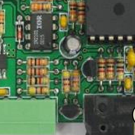


6 4. BOARD LAYOUT Components on BLD04A BLD04A pins orientation Components on BLD04A and their functions: 1. Fuse (5A) To protect the BLD04A. Created by Cytron Technologies Sdn. Bhd. All Rights Reserved 6
7 2. Pluggable Terminal Block Connect to motor and power source. Pin No. Pin Name Wire Color Description 1 +24V Red Positive supply. 2 Ground Black Negative supply. ROBOT. HEAD to TOE 3 Motor Coil A White Connect to motor coil A. 4 Motor Coil B Blue Connect to motor coil B. 5 Motor Coil C Green Connect to motor coil C. 6 +5V Red Positive supply to the hall sensor. 7 Ground Black Negative supply to the hall sensor. 8 Hall Sensor A White Connect to hall sensor A. 9 Hall Sensor B Blue Connect to hall sensor B. 10 Hall Sensor C Green Connect to hall sensor C. 3. FRC Header Parallel IO interface Pin No. Pin Name Description 1 Start/Stop* Internally pulled high, active low. 2 Run/Brake* Internally pulled high, active low. 3 Direction* Internally pulled high, active low. 4 Alarm Reset* Internally pulled high, active low. 5 VRH Connect to the higher terminal of external potentiometer for speed control. 6 Speed Input PWM or analog voltage (0 5V) input for speed control. 7 VRL Connect to the lower terminal of external potentiometer for speed control. 8 Ground Logic ground. 9 Encoder Output** Open Collector output, 12 pulses per revolution. 10 Alarm Output** Open Collector output, active low. Created by Cytron Technologies Sdn. Bhd. All Rights Reserved 7
8 * These pins are TTL / CMOS compatible and are internally pulled high. They can be controlled by a microcontroller output or a switch. ** These pins are open collector outputs. When they are connected to the input of the microcontroller, an external pull up resistor (1K 10K Ohm). Pin 1 (Start/Stop) and pin 2 (Run/Brake) These 2 pins are used together to control the movement of the brushless motor. The effects of each pin are as follow: Pin 1 (Start/Stop) Pin 2 (Run/Brake) Description X (Don t Care) High Motor stops instantaneously (brake) High Low Motor stops naturally (free running stop) Low Low Motor rotates Pin 3 (Direction) This pin controls the direction of the motor. The actual direction of the motor depends on the gear ratio of the gearbox. Linix BLDC Motor 45ZWN10-5G 45ZWN10-15G 45ZWN30-20G 45ZWN10-30G 45ZWN30-10G Pin 3 (Direction) High (1) Low (0) High (1) Low (0) Direction of the output shaft after gearbox (As viewed into the output shaft) Counter-Clockwise Clockwise Clockwise Counter-Clockwise Pin 4 (Alarm Reset) When the error alarm is triggered, setting this pin to low level will reset the alarm. Please return the Start/Stop or Run/Brake input to high level before resetting the alarm. The alarm will not be reset if both inputs are at low level. Pin 5 (VRH) When speed control by potentiometer is desired, this pin is connected to the higher pin of the potentiometer. Please refer to figure below for the connection. Created by Cytron Technologies Sdn. Bhd. All Rights Reserved 8
 When speed control by potentiometer is desired, this pin is connected to the lower pin of the potentiometer. Please refer to figure below for the connection.")
 This pin will be triggered (pulled to low) when there is an error occurred. 4.")
9 Pin 6 (Speed Input) The speed of the motor can be controlled by the analog voltage (0 5V DC) or PWM signals on this pin. Please refer to figure below for the connection. Pin 7 (VRH) When speed control by potentiometer is desired, this pin is connected to the lower pin of the potentiometer. Please refer to figure below for the connection. Pin 8 (Ground) Connect this pin to the ground of the host. Pin 9 (Encoder Output) The BLD04A will output 12 pulses per motor rotation (before gearbox) on this pin. This can be used to determine the speed and number of rotations for the motor. Pin 10 (Alarm Output) This pin will be triggered (pulled to low) when there is an error occurred UART interface. Pin No. Pin Name Description 1 UART Rx 5V UART receive pin. 2 UART Tx 5V UART transmit pin. 3 Ground Logic ground. 4 Not Connected Leave this pin disconnected. 5. Test Button When this button is pressed, the motor will rotate at speed This is to fast check the condition of the BLD04A. (This does not work in serial control mode). Created by Cytron Technologies Sdn. Bhd. All Rights Reserved 9
10 6. Closed Loop Selection Jumper Short this jumper for closed loop speed control, open it for open loop speed control (This need to be configured before power on the board). 7. Red LED Error Alarm LED. The number of flashes indicates the type of alarm. Number of Flashes Alarm Description Off No Alarm No error has been detected. 2 Overvoltage Input voltage is > 28V 3 Undervoltage Input voltage is < 20V 4 Out-Of-Phase 5 Overload The motor hall sensors state are invalid (Bad motor or loose connection). The motor has been overloaded for more than 5 seconds. 8. Yellow LED Speed Control Mode Indicator. Light on when closed loop speed control is selected. 9. Green LED Power LED. Light on when the board is powered up. Created by Cytron Technologies Sdn. Bhd. All Rights Reserved 10
11 5. INSTALLATION AND GETTING STARTED 5.1 Setting Speed Control Mode (Open/Closed Loop) The mode of operation can be configured by JP2. The BLD04A PCB board needs to be disassembled from the casing in order to access this jumper. The speed control mode must be configured before power up the BLD04A. Once the board is powered up, any changes to the jumper status will be ignored. The default mode when shipped is Open Loop mode. Short this jumper for closed loop speed control and leave it open for open loop speed control. The different between closed loop and open loop speed control are as follow: Open Loop The speed of the motor is controlled by the PWM signal which duty cycle is directly proportional to the speed input. The actual speed of the motor may be different depending on the load of the motor. This mode of operation will provide wider speed range for the motor (250rpm 3500rpm). Closed Loop The speed of the motor is controlled by a PI controller which will monitor the actual speed of the motor and alter the duty cycle of the PWM signal so that the actual speed will follow the speed input as close as possible. In this mode, the actual speed of the motor will be consistent disregarding the load of the motor. This is especially useful when the motor is used to drive the robot over the ramp. However, this operation mode has a limited speed range (400rpm 3000rpm) compared to the open loop speed control. Other than that, the motor may jerk when operates without any load. The problem will go away when the motor is under load. Created by Cytron Technologies Sdn. Bhd. All Rights Reserved 11


12 Below are the steps to disassemble the casing of the BLD04A and configure JP2 from Open Loop mode to Closed Loop mode. 1. Figure below shows the BLD04A with casing. We need to remove the casing to configure JP2. 2. Remove the screws and the face plate of the casing. Created by Cytron Technologies Sdn. Bhd. All Rights Reserved 12


13 ROBOT. HEAD to TOE 3. Figure below shows the BLD40A after screws and face plate are removed. 4. Remove the BLD04A board from its casing. Created by Cytron Technologies Sdn. Bhd. All Rights Reserved 13

14 5. Configure JP2 from Open Loop to Closed Loop. Before - Open Loop mode After Closed Loop Mode 6. Put back the BLD04A board into the casing and assemble back the face plate. Created by Cytron Technologies Sdn. Bhd. All Rights Reserved 14
15 5.2 UART Communication Protocol The BLD04A supports 2 types of interface Parallel IO and UART. By default, the BLD04A operates in parallel control mode where the motor is controlled by the input from the parallel IO interface. Once the BLD04A receives any valid command from the host, it will operate in the UART control mode since then and any changes on the parallel IO interface are neglected. To return back to the parallel control mode, the host need to send a Set Parallel Control command to the BLD04A. Another alternative will be power off and power on again the BLD04A. In this section, the protocol for UART control mode is explained. The default baud rate is 9600bps. Created by Cytron Technologies Sdn. Bhd. All Rights Reserved 15

16 Created by Cytron Technologies Sdn. Bhd. All Rights Reserved 16
17 Testing UART Communication ROBOT. HEAD to TOE To test the UART communication, the host need to send 3 bytes of data one by one to the BLD04A. First 2 bytes are headers and third byte is command to test the UART communication. i. 1 st byte: Send header 1 0x00 ii. iii. 2 nd byte: Send header 2 0x00 3 rd byte: Send command 0xAA After sending 3 bytes of data, host will receive 3 bytes of data from the BLD04A. i. 1 st byte: Receive header 1 0x00 ii. 2 nd byte: Receive header 2 0x00 iii. 3 rd byte: Receive data 0xAA Set UART Baudrate UART Baudrate can be set by sending 5 bytes of data from host to BLD04A. The value of baudrate must only be 0 5. i. 1 st byte: Send header 1 0x00 ii. 2 nd byte: Send header 2 0x00 iii. 3 rd byte: Send command 0x22 iv. 4 th byte: Send data 0x00 v. 5 th byte: Send value of baudrate (0 5) Stop/Brake/Run/Set Direction/Reset Alarm/Set Parallel Control 3 bytes of data need to be sent for stop, brake, run, set direction, reset alarm and set parallel control. The first 2 bytes are headers and the third byte is the command to stop, brake, run, set direction, reset alarm and set parallel control. i. 1 st byte: Send header 1 0x00 ii. 2 nd byte: Send header 2 0x00 iii. 3 rd byte: Send command to stop, brake, run, set direction, reset alarm and set parallel control Created by Cytron Technologies Sdn. Bhd. All Rights Reserved 17
18 Set Speed ROBOT. HEAD to TOE 5 bytes of data is needed to control the speed of the motor. The value of the speed must only be i. 1 st byte: Send header 1 0x00 ii. 2 nd byte: Send header 2 0x00 iii. 3 rd byte: Send command to set the motor speed 0xF6 iv. 4 th byte: Send MSB value of speed v. 5 th byte: Send LSB value of speed Read Speed Host need to send 3 bytes of data to read the motor speed. The value returned to the host is the speed of the motor in rpm. i. 1 st byte: Send header 1 0x00 ii. 2 nd byte: Send header 2 0x00 iii. 3 rd byte: Send command 0xF8 After sending 3 bytes of data, host will receive 4 bytes of data from the BLD04A. i. 1 st byte: Receive header 1 0x00 ii. 2 nd byte: Receive header 2 0x00 iii. 3 rd byte: Receive MSB value of speed iv. 4 th byte: Receive LSB value of speed Read Alarm State 3 bytes of data will be sent to read the alarm state. i. 1 st byte: Send header 1 0x00 ii. 2 nd byte: Send header 2 0x00 iii. 3 rd byte: Send command 0xF9 Then host will receive 4 bytes of data from BLD04A. i. 1 st byte: Receive header 1 0x00 ii. 2 nd byte: Receive header 2 0x00 iii. 3 rd byte: Receive data 0x00 iv. 4 th byte: Receive alarm value. Created by Cytron Technologies Sdn. Bhd. All Rights Reserved 18


19 5.3 Using BLD04A with AR40B / IFC-BL02 Guide for making 10 ways cable This cable is used to interface Brushless Motor Driver with Parallel IO interface. 10 ways of rainbow cable will be used on a female connector. 2 pins from connector are unused which are pin1 and pin5. Created by Cytron Technologies Sdn. Bhd. All Rights Reserved 19


20 Please refer to IFC-BL02 User s Manual for IFC-BL02 hardware installation. Connect the driver with the brushless motor to IFC-BL02 as shown in below figure. 1. Connect Pluggable Terminal Block from brushless motor to BLD04A. 2. Connect power supply (thick red and black wire) to IFC-BL02 card. 3. Connect Parallel I/O cable from BLD04A to IFC-BL02. Created by Cytron Technologies Sdn. Bhd. All Rights Reserved 20


21 Pin Connection 2 VCC 1 GND Pin Connection 12 Alarm Output 11 Encoder Output 10 Ground 9 VRL 8 Speed Input 7 VRH 6 Alarm Reset 5 NC 4 Direction 3 Run/Brake 2 Start/Stop 1 NC Created by Cytron Technologies Sdn. Bhd. All Rights Reserved 21


22 5.4 Using BLD04A with Microcontroller (Parallel Mode) Sample source code is provided to show how to interface BLD04A with SK40B/SK40C in Parallel Control Mode. The sample source code does not demonstrate all the features of BLD04A. The connection between the Parallel IO Interface of the BLD04A and the SK40B/SK40C is as below: For this sample source code, every time the SW1 is pressed and released, the motor will go through the following cycle: Free-Running Stop Rotate at half speed with direction 1 Brake Rotate at full speed with direction 0 Repeat again Created by Cytron Technologies Sdn. Bhd. All Rights Reserved 22


23 Connect the BLD04A to microcontroller as shown in figure below. This example uses SK40C as the host. 1. Connect Pluggable Terminal Block from brushless motor to BLD04A. 2. Connect power supply (thick red and black wire) to 24V power source. 3. Connect Parallel I/O cable from BLD04A to SK40C. Created by Cytron Technologies Sdn. Bhd. All Rights Reserved 23


24 5.5 Using BLD04A with Microcontroller (UART Mode) Sample source code in UART mode is also provided to show how to use the BLD04A with SK40C/SK40B in UART Control Mode. Sample source code can be downloaded from the website. However, the sample source code does not demonstrate all the features of BLD04A. For this sample source code, every time the SW1 is pressed and released, the motor will go through the following cycle: Free-Running Stop Rotate at half speed with direction 1 Brake Rotate at full speed with direction 0 Repeat again Created by Cytron Technologies Sdn. Bhd. All Rights Reserved 24


25 ROBOT. HEAD to TOE Connect the BLD04A to microcontroller as shown in figure below. This example uses SK40C as the host. 1. Connect Pluggable Terminal Block from brushless motor to BLD04A. 2. Connect power cable (thick red and black wire) to 24V power source. 3. Connect UART cable from BLD04A to SK40C. Rx and Tx pin is cross connected Created by Cytron Technologies Sdn. Bhd. All Rights Reserved 25

26 5.6 Using BLD04A with PC (UART Mode) Besides controlling the BLD04A with a microcontroller, we also provide GUI to control the motor from a PC. UC00A is needed for UART communication between BLD04A and PC. Please refer to UC00A User s Manual for more details about the product. 1. Connect Pluggable Terminal Block from brushless motor to BLD04A. 2. Connect power source wire (thick red and black wire) to 24V power source. 3. Connect UC00A to PC USB port and another end of UC00A to UART port of BLD04A. Created by Cytron Technologies Sdn. Bhd. All Rights Reserved 26


27 4. Open BLD04A GUI folder and click on Setup. BLD04A GUI can be downloaded from the website. User may already have the.net framework installed on PC, especially if users have already installed other applications which were built with one of the Visual Studio 2005.NET languages. If you do not yet have it, the.net framework can be freely downloaded from Microsoft's website. Users of Windows Vista do not need to install the.net framework, as it comes pre-installed as part of the OS. 5. Click Install to install the BLD04A GUI. Created by Cytron Technologies Sdn. Bhd. All Rights Reserved 27


28 6. Run the GUI. Warning massage may appear if you do not have any COM port on your PC. Plug in the UC00A and click OK. 7. Figure below show the BLD04A GUI. Select the COM Port which is connected to the BLD04A and the correct baud rate. The default baud rate is 9600bps. 8. Click Connect and buttons for motor control will be enabled. The movement of the motor can be controlled by clicking the corresponding button and the speed may be changed by using the Set Speed slide bar. Besides that, the motor speed can be obtained by clicking the Start button under the Read Speed panel. The speed of the motor will be ploted on the graph as shown below. Created by Cytron Technologies Sdn. Bhd. All Rights Reserved 28

29 Created by Cytron Technologies Sdn. Bhd. All Rights Reserved 29
30 6. WARRANTY Product warranty is valid for 6 months. Warranty only applies to manufacturing defect. Damage caused by miss-use is not covered under warranty. Warranty does not cover freight cost for both ways. Prepared by Cytron Technologies Sdn. Bhd. 19, Jalan Kebudayaan 1A, Taman Universiti, Skudai, Johor, Malaysia. Tel: Fax: URL: support@cytron.com.my sales@cytron.com.my Created by Cytron Technologies Sdn. Bhd. All Rights Reserved 30
Cytron USB to UART Converter UC00A
 Cytron USB to UART Converter UC00A User s Manual V1.1 August 2009 Information contained in this publication regarding device applications and the like is intended through suggestion only and may be superseded
IFC-EB02 Interface Free Controller Extension Board
 IFC-EB02 Interface Free Controller Extension Board User s Manual V1.1 Apr 2008 Information contained in this publication regarding device applications and the like is intended through suggestion only and
RE08A Rotary Encoder Kit
 RE08A Rotary Encoder Kit User s Manual V1.5 November 2011 Information contained in this publication regarding device applications and the like is intended through suggestion only and may be superseded
IFC-MD15A Interface Free Controller Brush Motor Card
 IFC-MD15A Interface Free Controller Brush Motor Card User s Manual V1.0 Oct 2008 Information contained in this publication regarding device applications and the like is intended through suggestion only
IFC-OC04 Interface Free Controller Output Card
 IFC-OC04 Interface Free Controller Output Card User s Manual V1.1 Apr 2008 Information contained in this publication regarding device applications and the like is intended through suggestion only and may
PS2 Controller Starter Kit SKPS
 PS2 Controller Starter Kit SKPS User s Manual V1.0 Oct 2008 Information contained in this publication regarding device applications and the like is intended through suggestion only and may be superseded
SK18A. 18 Pins PIC START-UP KIT. User s Manual V1.1. Dec 2007
 SK18A 18 Pins PIC START-UP KIT User s Manual V1.1 Dec 2007 Information contained in this publication regarding device applications and the like is intended through suggestion only and may be superseded
RFID: Read and Display V2010. Version 1.1. Sept Cytron Technologies Sdn. Bhd.
 PR8-B RFID: Read and Display V2010 Version 1.1 Sept 2010 Cytron Technologies Sdn. Bhd. Information contained in this publication regarding device applications and the like is intended through suggestion
SHIELD-MD10 Cytron 10A Motor Driver Shield
 SHIELD-MD10 Cytron 10A Motor Driver Shield User's Manual V1.0 October 2012 Created by Cytron Technologies Sdn. Bhd. All Right Reserved 1 Index 1. Introduction 3 2. Packing List 4 3. Product Specification
SK40C ENHANCED 40 PINS PIC START-UP KIT. User s Manual V1.3. March 2012
 SK40C ENHANCED 40 PINS PIC START-UP KIT User s Manual V1.3 March 2012 Information contained in this publication regarding device applications and the like is intended through suggestion only and may be
CYTRON USB PIC Programmer v2009 UP00B
 CYTRON USB PIC Programmer v2009 UP00B User s Manual V1.0 Nov 2008 Information contained in this publication regarding device applications and the like is intended through suggestion only and may be superseded
Cytron 3A Motor Driver Shield SHIELD-3AMOTOR. User s Manual Rev 1.0 April 2017
 Cytron 3A Motor Driver Shield SHIELD-3AMOTOR User s Manual Rev 1.0 April 2017 Information contained in this publication regarding device applications and the like is intended through suggestion only and
Display Real Time Clock (RTC) On LCD. Version 1.2. Aug Cytron Technologies Sdn. Bhd.
 On LCD. Version 1.2. Aug Cytron Technologies Sdn. Bhd.") Display Real Time Clock (RTC) On LCD PR12 Version 1.2 Aug 2008 Cytron Technologies Sdn. Bhd. Information contained in this publication regarding device applications and the like is intended through suggestion
Display Real Time Clock (RTC) On LCD PR12 Version 1.2 Aug 2008 Cytron Technologies Sdn. Bhd. Information contained in this publication regarding device applications and the like is intended through suggestion
SD02B 2A Stepper Motor Driver
 SD02B 2A Stepper Motor Driver User s Manual V1.2 July 2013 Information contained in this publication regarding device applications and the like is intended through suggestion only and may be superseded
SD02C 2A Stepper Motor Driver. User s Manual V1.0
 SD02C 2A Stepper Motor Driver User s Manual V1.0 APRIL 2016 Index ROBOT. HEAD to TOE 1. Introduction and Overview 3 1.0 Introduction of SD02C 3 1.1 System Overview 4 1.2 General Description 5 2. Packing
IFC-MB00 Interface Free Controller Main Board
 IFC-MB00 Interface Free Controller Main Board User s Manual V1.1 Apr 2008 Information contained in this publication regarding device applications and the like is intended through suggestion only and may
TC35 GSM Development Board
 TC35 GSM Development Board User s Manual V1.1 Mar 2014 Created by Cytron Technologies Sdn. Bhd. All Rights Reserved 1 Created by Cytron Technologies Sdn. Bhd. All Rights Reserved 2 Index 1. Introduction
Shield - GPS53. User's Manual. Dec 2014 V1.0. ROBOT. HEAD to TOE Product User s Manual Shield-GPS53
 Shield - GPS53 User's Manual V1.0 Dec 2014 Created by Cytron Technologies Sdn. Bhd. All Rights Reserved 1 Index 1. Introduction and Overview 3 2. Packing List 4 3. Dimension 5 4. Product Layout 6 5. Product
ESPWiFi Shield SHIELD ESP WIFI Rev2.0
 ESPWiFi Shield SHIELD ESP WIFI Rev2.0 User's Manual V2.0 April 2016 Created by Cytron Technologies Sdn. Bhd. All Right Reserved 1 Index 1. Introduction 3 2. Packing List 4 3. Board or Product Layout 5
Tic-Tac-Toe with mtouch. Version 1.0. June Cytron Technologies Sdn. Bhd.
 Tic-Tac-Toe with mtouch PR28 Version 1.0 June 2010 Cytron Technologies Sdn. Bhd. Information contained in this publication regarding device applications and the like is intended through suggestion only
915MHz 8-channel LoRa Gateway Hat for Raspberry Pi HAT-LRGW-915
 ROBOT. HEAD to TOE 915MHz 8-channel LoRa Gateway Hat for Raspberry Pi HAT-LRGW-915 User's Manual V1.0 Aug 2017 Created by Cytron Technologies Sdn. Bhd. All Right Reserved 1 Index 1. Introduction 3 2. Packing
RoboClaw 2x30A Dual Channel Motor Controller
 RoboClaw 2x30A, 34VDC Dual Channel Brushed DC Motor Controller Version 2.2 (c) 2016 Ion Motion Control. All Rights Reserved. Feature Overview: 60 Amps Peak Per Channel Channel Bridging Supported Dual Quadrature
EasyMP3 Shield SHIELD-EZMP3
 EasyMP3 Shield SHIELD-EZMP3 User's Manual V1.0 Apr 2016 Created by Cytron Technologies Sdn. Bhd. All Right Reserved 1 Index 1. Introduction 3 2. Packing List 4 3. Board or Product Layout 5 4. Dimension
DC BRUSHLESS MOTOR CONTROLLER BLSD-20/BLSD-50
 1. Product designation DC BRUSHLESS MOTOR CONTROLLER BLSD-20/BLSD-50 with RS-485 interface Manual BLSD.20.50.001 Brushless controllers BLSD-20 and BLSD-50 are electronic devices to operate and control
RoboClaw 120A/160A/200A Dual Channel Motor Controller
 RoboClaw 2x160A, 34VDC Dual Channel RoboClaw 2x120AHV, 60VDC Dual Channel RoboClaw 2x160AHV, 60VDC Dual Channel RoboClaw 2x200AHV, 60VDC Dual Channel Brushed DC Motor Controllers Version 2.1 (c) 2016 Ion
Maker Uno MAKER-UNO. User s Manual. Rev 1.0 Dec 2017
 Maker Uno MAKER-UNO User s Manual Rev 1.0 Dec 2017 Informa on contained in this publica on regarding device applica ons and the like is intended through sugges on only and may be superseded by updates.
DEV-1 HamStack Development Board
 Sierra Radio Systems DEV-1 HamStack Development Board Reference Manual Version 1.0 Contents Introduction Hardware Compiler overview Program structure Code examples Sample projects For more information,
Absolute Encoder Multiturn
 Absolute Encoder Multiturn Features Resolution: Singleturn: up to 16,384 (14 Bit) steps per revolution Multiturn: up to 16,777,216 (24 Bit) revolutions Interface: SSI (synchron serial interface) or BiSS
EZ-24 EZ-24-HTB EZ-24-HTBS. Version May Publication PR-1100
 FAMILY EZ-24 EZ-24-HTB EZ-24-HTBS Version 11.7 May 2017 Publication PR-1100 Module firmware and functionality is protected by U.S. and international patents. For complete patent information visit www.pulseroller.com/patents
- Electronic Limit Switches - Very Accurate - Easy to use - Robust - Dependable - High Resolution - Non Contact Measurement - Wide Temp.
 1-30-2018 EPS 02 Operating Instructions RACO Electronic Position Sensor - Electronic Limit Switches - Very Accurate - Easy to use - Robust - Dependable - High Resolution - Non Contact Measurement - Wide
Product Specification for SAB-S-MODBUS
 SAB-S-MODBUS May 9, 2011 Product Specification for SAB-S-MODBUS The SAB-S-MODBUS is a two-channel module that measures single or multiple magnet transducer position and returns this information to a host
SMART MOTOR DEVICES BxSD program Manual
 SMART MOTOR DEVICES http://www.stepmotor.biz BxSD program Manual 2015 1.PROGRAM ASSIGNMENT... 3 2. USER INTERFACE... 3 3. PORT SELECTION AND SETUP... 4 4. NEW ADDRESS OF THE CONTROLLER SETTING... 5 5.
Cytron RFM LoRa Shield SHIELD-LORA-RFM
 Cytron RFM LoRa Shield SHIELD-LORA-RFM User's Manual V1.0 March 2017 Created by Cytron Technologies Sdn. Bhd. All Right Reserved 1 Index 1. Introduction 3 2. Packing List 4 3. Board or Product Layout 5
Digital Servo Drive. For Brushless Motor or Brushed Motor MDSC4805 / MDSC4810 / MDSC4830 / MDSC4850. Datasheet V1.1. Jun 2, 2017
 Digital Servo Drive For Brushless Motor or Brushed Motor MDSC4805 / MDSC4810 / MDSC4830 / MDSC4850 Datasheet V1.1 Jun 2, 2017 Copyright @ Mach Motion Products, INC. 2017 All rights reserved. No part of
MC Connector Wiring Diagrams
 Page of MC Connector Wiring Diagrams Version: 0-0-0 This manual supports: MCHP-L MCHP-R Index MCHP connectors... Fuses... I/O connector... Encoder connector... Support... MCHP connectors Page of Fuses
AirCare General Purpose ModBus Interface ACM1001. OptiDrive Modbus Module Product Specification. For assistance call
 OptiDrive Modbus Module Product Specification AirCare General Purpose ModBus Interface ACM1001 Features Modbus RTU network interface Works with any Invertek OptiDrive Closed loop control optio - External
GSV-3USBx2 3,5mV/V 4,2V
 x2 3,5mV/V 4,2V Highlights Powered via USB port Sampling rate 10 khz Data rate 1...1000 Hz straingage quarter, half, full bridges Built-in bridge supplement 350 Ohm Optionally also for displacement transducers
F2MC MB90385 series Evaluation Board Documentation. Revision Date Comment V New document
 F2MC MB90385 series Evaluation Board Documentation Revision Date Comment V1.0 08.25.02 New document 1 Warranty and Disclaimer To the maximum extent permitted by applicable law, Fujitsu Microelectronics
Screw. Nut Guide. Features
 Actuator Controls Rotary Limit Switches SKA Series Rotary Limit Switch Screw Traveling Nuts Input Shaft Nut Guide Gear Precision Available in two control voltage ratings: 250 or 480, and in three gear
BLWS23MDCUSB Series. Programmable Brushless DC Motor Controller. User s Guide
 BLWS23MDCUSB Series Programmable Brushless DC Motor Controller User s Guide A N A H E I M A U T O M A T I O N 4985 E. Landon Drive Anaheim, CA 92807 e-mail: info@anaheimautomation.com (714) 992-6990 fax:
4.8 Expansion Module MAC00-FS1/FS4
 .8 Expansion Module MAC00-FS/FS MAC00-FS With M connectors MAC00-FS With D sub connectors TT08GB.8. High speed serial RS8 module MAC00-FS and FS Introduction The MAC00-FS and FS are used for high speed
Quick Start Guide KEA128BLDCRD. 3-phase Sensorless BLDC Motor Control Reference Design using Kinetis KEA128
 Quick Start Guide KEA128BLDCRD 3-phase Sensorless BLDC Motor Control Reference Design using Kinetis KEA128 Quick Start Guide Get to Know: 3-phase Sensorless BLDC Motor Control Reference Design using Kinetis
TLE9869 Eval.Kit V1.0 Users Manual
 TLE9869 Eval.Kit V1.0 Users Manual Contents Abbreviations... 2 1 Concept... 3 2 Interconnects... 4 3 Test Points... 5 4 Jumper Settings... 6 5 Communication Interfaces... 7 5.1 LIN (via Banana jack and
ARDUINO MEGA 2560 REV3 Code: A000067
 ARDUINO MEGA 2560 REV3 Code: A000067 The MEGA 2560 is designed for more complex projects. With 54 digital I/O pins, 16 analog inputs and a larger space for your sketch it is the recommended board for 3D
motioncookie SYSTEM IN A PACKAGE
 motioncookie SYSTEM IN A PACKAGE motioncookie TMCC160-EVAL MANUAL TMCC160 TMCL Hardware Version 1.1 Document Revision 1.0 2015-AUG-16 The TMCC160-EVAL is designed for evaluating all features of the TMCC160-LC
8051 Intermidiate Development Board. Product Manual. Contents. 1) Overview 2) Features 3) Using the board 4) Troubleshooting and getting help
 Overview 2) Features 3) Using the board 4) Troubleshooting and getting help") 8051 Intermidiate Development Board Product Manual Contents 1) Overview 2) Features 3) Using the board 4) Troubleshooting and getting help 1. Overview 2. Features The board is built on a high quality FR-4(1.6
8051 Intermidiate Development Board Product Manual Contents 1) Overview 2) Features 3) Using the board 4) Troubleshooting and getting help 1. Overview 2. Features The board is built on a high quality FR-4(1.6
Version 1.7. Module Firmware Version 4
 Version 1.7 Module Firmware Version 4 January 2018 Publication EZQ-1000 Module firmware and functionality is protected by U.S. and international patents. For complete patent information visit www.pulseroller.com/patents
HUB-ee BMD-S Arduino Proto Shield V1.1
 HUB-ee BMD-S Arduino Proto Shield V1.1 User guide and assembly instructions Document Version 0.5 Introduction & Board Guide 2 Schematic 3 Quick User Guide 4 Assembly Guide 6 Kit Contents 7 1) Diodes and
Technical Manual. Stepper controller SMCI12. NANOTEC ELECTRONIC GmbH & Co. KG Gewerbestraße 11 D Landsham near Munich, Germany
 Technical Manual Stepper controller NANOTEC ELECTRONIC GmbH & Co. KG Gewerbestraße 11 D-85652 Landsham near Munich, Germany Tel. +49 (0)89-900 686-0 Fax +49 (0)89-900 686-50 info@nanotec.de Editorial Editorial
ARDUINO M0 PRO Code: A000111
 ARDUINO M0 PRO Code: A000111 The Arduino M0 Pro is an Arduino M0 with a step by step debugger With the new Arduino M0 Pro board, the more creative individual will have the potential to create one s most
Hybrid AC Driver [GCNC-1110]
![Hybrid AC Driver [GCNC-1110]](/thumbs/86/94474371.jpg "Hybrid AC Driver [GCNC-1110]") Page 1 Installation Manual and Datasheet Page 2 Key Features Smooth and quiet operation at all speeds and extremely low motor heating Industrial grade performance for an alternating current servo motor
Page 1 Installation Manual and Datasheet Page 2 Key Features Smooth and quiet operation at all speeds and extremely low motor heating Industrial grade performance for an alternating current servo motor
DIO16 8 Channel digital input and 8 Channel digital output board. V1.0 August CANBUS-DIO16 Rev B v1.0
 DIO16 8 Channel digital input and 8 Channel digital output board V1.0 August 2017 Product name Model number Manufacturer DIO16 8 Channel digital input and 8 Channel digital output board CANBUS-DIO16 SK
CU2/CUF Connector Wiring Diagrams
 Page of CU/CUF CONNECTOR WIRING DIAGRAMS CU/CUF Connector Wiring Diagrams Version: 0-0-0 This manual supports: CUFHP - CUHP - CUXJ - CUXJ00 Index CU/CUF connectors... Fuses... I/O connector... Encoder
TMCM-142-IF. Hardware Manual
 TMCM-142-IF Hardware Manual Version: 1.01 2009-JUL-31 Trinamic Motion Control GmbH & Co KG Sternstraße 67 D - 20 357 Hamburg, Germany http://www.trinamic.com TMCM-142-IF Manual (V1.01/2009-JUL-31) 2 Table
Quick Start Guide: RL78G14 Motor Control Starter Kit
 Document Contents 1.0 Introduction 1 2.0 Board Layout 1 3.0 Stand Alone Demonstration Mode 2 4.0 Installation 3 5.0 Using the GUI 4 6.0 RL78/G14 Programming 6 7.0 RL78/G14 Debugging 7 8.0 Next Steps 8
Data Sheet MEM 22. Absolute Encoder Multiturn
 Absolute Encoder Multiturn Features Resolution: Singleturn: up to 16,384 (14 Bit) steps per revolution Multiturn: up to 16,777,216 (24 Bit) revolutions Interface: SSI (synchron serial interface) or BiSS
DT-ROBOT Line Follower
 DT-ROBOT Line Follower Trademarks & Copyright AT, IBM, and PC are trademarks of International Business Machines Corp. Pentium is a registered trademark of Intel Corporation. Windows is a registered trademark
Arduino Uno. Arduino Uno R3 Front. Arduino Uno R2 Front
 Arduino Uno Arduino Uno R3 Front Arduino Uno R2 Front Arduino Uno SMD Arduino Uno R3 Back Arduino Uno Front Arduino Uno Back Overview The Arduino Uno is a microcontroller board based on the ATmega328 (datasheet).
Motorized Capacitor. Electrical Installation of ID-400. Service Bulletin 63
 Plasma Control Technologies Service Bulletin 63 Motorized Capacitor Electrical Installation of ID-400 Document Information Authors... O. Lehmann / A. Renggli / T. Fenske... W. Bigler / M. Armbruster Document...
APPLICATION NOTE /20/02 Getting started using IPM240-5E with a brushless motor
 Problem: For new users of an intelligent drive, starting to implement a motion control application can be a quite complex task. You need to know how to hook-up the components of the motion system, to configure
BASICMICRO. MCP26x Dual Channel Motor Controller. MCP26x Dual Channel Programmable Brushed DC Motor Controller
 BASICMICRO MCP26x Dual Channel Programmable Brushed DC Motor Controller (c) 2016 Basicmicro. All Rights Reserved. Feature Overview: 60 Amps per channel continuous for two brushed DC motors 120 Amps in
Power Supply, Arduino MEGA 2560, and Stepper Motors Connections
 Power Supply, Arduino MEGA 2560, and Stepper Motors Connections By: Maram Sulimani Abstract: Arduino MEGA 2560 is required for this project to control the movement of the 3D printer axis and its extruder.
Data Sheet MEM 16. Absolute Encoder Multiturn
 Absolute Encoder Multiturn Features Resolution: Singleturn: up to 8,192 (13 Bit) steps per revolution Multiturn: up to 4,294,967,296 (32 Bit) revolutions Interface: SSI (synchron serial interface) or BiSS
DEVKIT-MOTORGD QUICK START GUIDE (QSG) Ultra-Reliable MCUs for Industrial and Automotive Applications. EXTERNAL USE
 Ultra-Reliable MCUs for Industrial and Automotive Applications. EXTERNAL USE") DEVKIT-MOTORGD QUICK START GUIDE (QSG) Ultra-Reliable MCUs for Industrial and Automotive Applications www.nxp.com/devkit-motorgd Contents Step-by-Step Installation Instructions How to Spin the Motor Hardware:
DEVKIT-MOTORGD QUICK START GUIDE (QSG) Ultra-Reliable MCUs for Industrial and Automotive Applications www.nxp.com/devkit-motorgd Contents Step-by-Step Installation Instructions How to Spin the Motor Hardware:
LV8414CSGEVK V1.0 Evaluation Kit User Guide
 LV8414CSGEVK V1.0 Evaluation Kit User Guide 03/25/2016 1 www.onsemi.com NOTICE TO CUSTOMERS The LV8414CS Evaluation Kit is intended to be used for ENGINEERING DEVELOPMENT, DEMONSTRATION OR EVALUATION PURPOSES
AD VL M1S + AD VM M1S AD VL M2S + AD VM M2S AD VL M3S + AD VM M3S AD VM M3SP
 Stepper Motor DRIVER Constant Voltage Mode USER MANUAL AD VL M1S + AD VM M1S AD VL M2S + AD VM M2S AD VL M3S + AD VM M3S AD VM M3SP Page 2 of 23 Release tracking File Description Date V4900UM230904_VD-R0
8 Port USB to RS- 232/422/485 Octal Adapter. Product Manual. Coolgear, Inc. Version 1.1 April 2018 Model Number: USB-8COMi-RM.
 8 Port USB to RS- 232/422/485 Octal Adapter Product Manual Coolgear, Inc. Version 1.1 April 2018 Model Number: USB-8COMi-RM 2 USB-8COMi-RM Product Manual Revision History Revision Date Author Comments
Section 4 - Automation Assembly
 Table of Contents 1. Process Control Unit (PCU) 1.1 Introduction 1.2 PCU Power Cable 1.3 Display and input controls 1.4 Analog Inputs 1.5 FET Outputs 1.6 Thermocouple Connectors 1.7 Table of Thermocouples
MCP230 Dual Channel Motor Controller
 MCP230A Dual Channel Programmable Brushed DC Motor Controller (c) 2015 Ion Motion Control. All Rights Reserved. Feature Overview: 30 Amps per channel continuous for two brushed DC motors 60 Amps in bridged
LOW VOLTAGE BLDC MOTOR CONTROLLER
 DESCRIPTION The D113-024D10/036D10/050D05 are members of a DSP based low voltage brushless DC motor controller family. The controllers are for controlling the brushless DC motor with or without Hall position
Additional board ZIB2-PDx-N for Plug & Drive motors PDx-N
 Additional board ZIB2-PDx-N for Plug & Drive motors PDx-N Technical data Operating voltage: Interface: 24 48 V DC or Application information PDx-N motor side connection X2 motor power Pin no. Name PD2-N-2
DG0598 Demo Guide SmartFusion2 Dual-Axis Motor Control Starter Kit
 DG0598 Demo Guide SmartFusion2 Dual-Axis Motor Control Starter Kit Microsemi Corporate Headquarters One Enterprise, Aliso Viejo, CA 92656 USA Within the USA: +1 (800) 713-4113 Outside the USA: +1 (949)
Product Manual. 2 Port USB to RS-422 /485 Optical Isolated Adapter. Coolgear, Inc. Version 1.1 March 2018 Model Number: USB-2COMi-Si-M
 2 Port USB to RS-422 /485 Optical Isolated Adapter Product Manual Coolgear, Inc. Version 1.1 March 2018 Model Number: USB-2COMi-Si-M 2 USB-2COMi-Si-M Product Manual Revision History Revision Date Author
USB485. USB to RS485 Converter Card. User Manual for connecting with Windows Vista Version 1.01
 USB485 USB to RS485 Converter Card User Manual for connecting with Windows Vista Version 1.01 RMS Technologies 2533 N. Carson St. #4698, Carson City, NV 89706-0147 1-877- 301-3609 www.rmsmotion.com sales@rmsmotion.com
VEX ARM Cortex -based Microcontroller and VEXnet Joystick User Guide
 1. VEX ARM Cortex -based Microcontroller and VEXnet Joystick Pairing Procedure: a. The Joystick must first be paired to the VEX ARM Cortex -based Microcontroller before they will work using VEXnet Keys.
Date 18/05/17. Operation and maintenance instructions for driver configurator QSet
 Operation and maintenance instructions 28 1. General recommendations The recommendations regarding safe use in this document should be observed at all times. Some hazards can only be associated with the
Technical Manual. Stepper controller SMCI12. NANOTEC ELECTRONIC GmbH & Co. KG Kapellenstraße 6 D Feldkirchen b.
 Stepper controller NANOTEC ELECTRONIC GmbH & Co. KG Kapellenstraße 6 D-85622 Feldkirchen b. Munich, Germany Tel. +49 (0)89-900 686-0 Fax +49 (0)89-900 686-50 info@nanotec.com Editorial Editorial 2013 Nanotec
PAS 9715/AO ENGINEERING SPECIFICATION
 Document PAS7 DOC Revision B (7//) PAS 975/AO ENGINEERING SPECIFICATION 32 CHANNEL, 2 BIT VME ANALOG OUTPUT CARD PCB REVISION B (4/2/999) Additional copies of this manual or other Precision Analog Systems
CHAPTER 3B: ELECTRONIC POWER STEERING
 Electronic Power Steering CHAPTER 3B: ELECTRONIC POWER STEERING NOTE: The basic steering system, such as the tie rod ends, drag links axles, etc., is covered in Chapter 3A: Steering. In 2012, Cub Cadet
WiFi to RS-232 adapter user manual
 WiFi to RS-232 adapter user manual WiFi to RS-232 adapter Package Contents: WiFi RS-232 adapter x 1 A4 User manual x 1 Mini USB Cable x 1 White Box Dimension: 11 x 6 x 5 (cm) Total Package Weight: 126
WIRING FOR MXL PRO- 05
 CONSTRUCTIVE DOCUMENTATION 0/0/005 WIRING Notes: general-purpose wiring for MXL PRO 05 CAR/BIKE installation Version.00 WIRING FOR MXL PRO- 05 MXL PRO 05 wiring (CAR/BIKES) Logger pinout: 7 pins Deutsch
Silverpak 17C/CE INTEGRATED STEP MOTOR, DRIVER AND CONTROLLER
 Silverpak 17C/CE INTEGRATED STEP MOTOR, DRIVER AND CONTROLLER With Encoder Option USER MANUAL Version 1.10 Thank you for purchasing the Silverpak 17C or 17CE integrated motor and controller with microstepping
Stepper motor driver HEM-545 last change:
 Documentation for Stepper motor driver HEM-545 last change: 16.03.2011 Functional description HEM-545 is a one channel motor driver for 2-phase stepping motors with pulse and direction interface. Motor
SmartFan Vortex. I2C Speed Control for 12 VDC Fans CONTROL RESOURCES INCORPORATED. The driving force of motor control & electronics cooling.
 The driving force of motor control & electronics cooling. SmartFan Vortex I2C Speed Control for 12 VDC Fans DC Controls P/N VOR5I400F SmartFan Vortex is an I2C fan speed control and alarm designed for
CORTEX Microcontroller and Joystick User Guide
 This is a User Guide for using the VEX CORTEX Microcontroller and VEX Joystick. Refer to the VEX Wiki (http://www.vexforum.com/wiki/index.php/vex_cortex_microcontroller) for updates to this document. 1.
EXL x240 Graphic LCD Smart Module 3,8 SHORT FORM TECHNICAL SPECIFICATIONS. Via di Corticella, Bologna, Italy
 320x240 Graphic LCD Smart Module 3,8 SHORT FORM TECHNICAL SPECIFICATIONS www.exelmicroel.it Via di Corticella, 201 40128 - Bologna, Italy Tel: +39 051 6380211 Fax: +39 051 6380226 exelbo@exelmicroel.it
USB-COMi-TB USB to Industrial Single RS-422 / 485 Adapter Manual. Specifications and Features
 USB-COMi-TB USB to Industrial Single RS-422 / 485 Adapter Manual The USB-COMi-TB USB-to-Industrial Single RS-422/485 Adapter is designed to make industrial communication port expansion quick and simple.
A Issue A Original. Instruction Manual. nxds Serial Comms Interface
 Instruction Manual A735-01-860 Issue A Original nxds Serial Comms Interface Description nxds6i nxds10i nxds15i nxds20i Item Number A735-01-983 A736-01-983 A737-01-983 A738-01-983 nxds6ic nxds10ic nxds15ic
Blue Point Engineering
 Overview DMX Duo driver board allows 2 Unipolar motors and 1 open collector output driver to be controlled from a DMX512 network. he board provides 2 independent motor drives, 1 external load driver and
BB-303 Manual Baseboard for TMCM-303
 BB-303 Manual Baseboard for TMCM-303 Trinamic Motion Control GmbH & Co. KG Sternstraße 67 D 20357 Hamburg, Germany http://www.trinamic.com BB-303 Manual (V1.04 / Jul 9th, 2007) 2 Contents 1 Features...
AS5161-EK-AB / AS5162-EK-AB 12 BIT Magnetic Angle Position Sensor
 User Manual AS5161 / AS5162 Adapterboard AS5161-EK-AB / AS5162-EK-AB 12 BIT Magnetic Angle Position Sensor www.ams.com Revision 1.0 / 2012/10/31 Table of Contents 1. General Description... 2 2. Package
DIGITAL COMPASS SOLUTION
 Features 5 Heading Accuracy, 0.5 Resolution 2-axis Capability Small Size (19mm x 19mm x 4.5mm), Light Weight Advanced Hard Iron Calibration Routine for Stray Fields and Ferrous Objects 0 to 70 C Operating
reprogrammable in BASIC
 Data Sheet Tinaxis+ Tinaxis+ DC400 INTELLIGENT DC motor control electronic Programmed and reprogrammable reprogrammable in BASIC 3 2 Jumpers RS485 - (B) RS485 + (A) GND RS485 (COM2) I/O Incremental Encoder
ARDUINO MEGA ADK REV3 Code: A000069
 ARDUINO MEGA ADK REV3 Code: A000069 OVERVIEW The Arduino MEGA ADK is a microcontroller board based on the ATmega2560. It has a USB host interface to connect with Android based phones, based on the MAX3421e
4.7 Expansion Module MAC00-FS1/FS4
 MAC00-FS4 With M12 connectors MAC00-FS1 With D sub connectors TT1068GB 4.7.1 High speed serial RS485 module MAC00-FS1 and FS4 Introduction The MAC00-FS1 and FS4 are used for high speed RS485 communication
SERIE 59. Rear clamp. Frontal clamp HIGH RESOLUTION HOLLOW SHAFT INCREMENTAL ENCODER FOR INDUSTRIAL APPLICATIONS
 HIGH RESOLUTION HOLLOW SHAFT INCREMENTAL ENCODER FOR INDUSTRIAL APPLICATIONS Resolution up to 50.000 pulses per turn External diameter 58 mm Hollow shaft from Ø 10 to 14 mm Protection class IP67 according
CDN503 HIGH DENSITY I/O ADAPTER USER GUIDE
 CDN503 HIGH DENSITY I/O ADAPTER USER GUIDE 13050301 (c) Copyright DIP Inc., 1996 DIP Inc. P.O. Box 9550 MORENO VALLEY, CA 92303 714-924-1730 CONTENTS DN503 PRODUCT OVERVIEW 1 DN503 INSTALLATION 1 POWER
Quick Start Guide for EV-MCS-LVDRV-Z Motor Drive Evaluation Platform Rev. 0.1
 Quick Start Guide for EV-MCS-LVDRV-Z Motor Drive Evaluation Platform Rev. 0.1 Created: Author: Last Modified: Modified by: 12/17/2014 12:17 PM Dara O Sullivan 1/6/2015 12:06 PM Dara O Sullivan ANALOG DEVICES
XE166 Family AP Application Note. Microcontrollers. X E D r i v e C a r d H a r d w a r e D e s c r i p t i o n Board REV.
 XE166 Family AP16160 X E 1 6 4 D r i v e C a r d H a r d w a r e D e s c r i p t i o n Application Note V1.0, 2009-03 Microcontrollers Edition 2009-03 Published by Infineon Technologies AG 81726 Munich,
USB-16COMi-M 16-Port RS-422/485 USB Serial Adapter User Manual. Features and Specifications. Power Supply
 USB-16COMi-M 16-Port RS-422/485 USB Serial Adapter User Manual The USB to industrial 16-Port RS-422/485 Adapter is designed to make serial port expansion quick and simple. Connecting to a USB port on your