Models 2601B, 2602B, and 2604B System SourceMeter Instruments Quick Start Guide
|
|
|
- Sharon Green
- 5 years ago
- Views:
Transcription


1 Models 2601B, 2602B, and 2604B System SourceMeter Instruments Quick Start Guide
2 Safety precautions Observe the following safety precautions before using this product and any associated instrumentation. Although some instruments and accessories would normally be used with nonhazardous voltages, there are situations where hazardous conditions may be present. This product is intended for use by qualified personnel who recognize shock hazards and are familiar with the safety precautions required to avoid possible injury. Read and follow all installation, operation, and maintenance information carefully before using the product. Refer to the user documentation for complete product specifications. If the product is used in a manner not specified, the protection provided by the product warranty may be impaired. The types of product users are: Responsible body is the individual or group responsible for use and maintenance of equipment, for ensuring that the equipment is operated within its specifications and operating limits, and for ensuring that operators are adequately trained. Operators use the product for its intended function. They must be trained in electrical safety procedures and proper use of the instrument. They must be protected from electric shock and contact with hazardous live circuits. Maintenance personnel perform routine procedures on the product to keep it operating properly, for example, setting the line voltage or replacing consumable materials. Maintenance procedures are described in the user documentation. The procedures explicitly state if the operator may perform them. Otherwise, they should be performed only by service personnel. Service personnel are trained to work on live circuits, perform safe installations, and repair products. Only properly trained service personnel may perform installation and service procedures. Keithley Instruments products are designed for use with electrical signals that are rated Measurement Category I and Measurement Category II, as described in the International Electrotechnical Commission (IEC) Standard IEC Most measurement, control, and data I/O signals are Measurement Category I and must not be directly connected to mains voltage or to voltage sources with high transient overvoltages. Measurement Category II connections require protection for high transient overvoltages often associated with local AC mains connections. Assume all measurement, control, and data I/O connections are for connection to Category I sources unless otherwise marked or described in the user documentation. Main supply voltage fluctuations not to exceed ±10 % of the nominal voltage. Exercise extreme caution when a shock hazard is present. Lethal voltage may be present on cable connector jacks or test fixtures. The American National Standards Institute (ANSI) states that a shock hazard exists when voltage levels greater than 30 V RMS, 42.4 V peak, or 60 V DC are present. A good safety practice is to expect that hazardous voltage is present in any unknown circuit before measuring. Operators of this product must be protected from electric shock at all times. The responsible body must ensure that operators are prevented access and/or insulated from every connection point. In some cases, connections must be exposed to potential human contact. Product operators in these circumstances must be trained to protect themselves from the risk of electric shock. If the circuit is capable of operating at or above 1000 V, no conductive part of the circuit may be exposed.
3 Do not connect switching cards directly to unlimited power circuits. They are intended to be used with impedance-limited sources. NEVER connect switching cards directly to AC mains. When connecting sources to switching cards, install protective devices to limit fault current and voltage to the card. Before operating an instrument, ensure that the line cord is connected to a properly-grounded power receptacle. Inspect the connecting cables, test leads, and jumpers for possible wear, cracks, or breaks before each use. When installing equipment where access to the main power cord is restricted, such as rack mounting, a separate main input power disconnect device must be provided in close proximity to the equipment and within easy reach of the operator. For maximum safety, do not touch the product, test cables, or any other instruments while power is applied to the circuit under test. ALWAYS remove power from the entire test system and discharge any capacitors before: connecting or disconnecting cables or jumpers, installing or removing switching cards, or making internal changes, such as installing or removing jumpers. Do not touch any object that could provide a current path to the common side of the circuit under test or power line (earth) ground. Always make measurements with dry hands while standing on a dry, insulated surface capable of withstanding the voltage being measured. The instrument and accessories must be used in accordance with its specifications and operating instructions, or the safety of the equipment may be impaired. Do not exceed the maximum signal levels of the instruments and accessories, as defined in the specifications and operating information, and as shown on the instrument or test fixture panels, or switching card. When fuses are used in a product, replace with the same type and rating for continued protection against fire hazard. Chassis connections must only be used as shield connections for measuring circuits, NOT as protective earth (safety ground) connections. If you are using a test fixture, keep the lid closed while power is applied to the device under test. Safe operation requires the use of a lid interlock. If a screw is present, connect it to protective earth (safety ground) using the wire recommended in the user documentation. This symbol on an instrument means caution, risk of danger. The user should refer to the operating instructions located in the user documentation in all cases where the symbol is marked on the instrument. This symbol on an instrument means caution, risk of electric shock. Use standard safety precautions to avoid personal contact with these voltages. This symbol on an instrument shows that the surface may be hot. Avoid personal contact to prevent burns. This symbol indicates a connection terminal to the equipment frame. If the mercury symbol is on a product, it indicates that mercury is present in the display lamp. Please note that the lamp must be properly disposed of according to federal, state, and local laws. WARNING This heading in the user documentation explains dangers that might result in personal injury or death. Always read the associated information very carefully before performing the indicated procedure. CAUTION This heading in the user documentation explains hazards that could damage the instrument. Such damage may invalidate the warranty. Instrumentation and accessories shall not be connected to humans. Before performing any maintenance, disconnect the line cord and all test cables.
4 To maintain protection from electric shock and fire, replacement components in mains circuits - including the power transformer, test leads, and input jacks - must be purchased from Keithley Instruments. Standard fuses with applicable national safety approvals may be used if the rating and type are the same. Other components that are not safety-related may be purchased from other suppliers as long as they are equivalent to the original component (note that selected parts should be purchased only through Keithley Instruments to maintain accuracy and functionality of the product). If you are unsure about the applicability of a replacement component, call a Keithley Instruments office for information. To clean an instrument, remove power from the instrument. Use a damp cloth or mild, water-based cleaner. Clean the exterior of the instrument only. Do not apply cleaner directly to the instrument or allow liquids to enter or spill on the instrument. Products that consist of a circuit board with no case or chassis (e.g., a data acquisition board for installation into a computer) should never require cleaning if handled according to instructions. If the board becomes contaminated and operation is affected, the board should be returned to the factory for proper cleaning and servicing. Power and environmental specifications For indoor use only. Supply voltage 100 V to 240 V AC, 50 Hz to 60 Hz (auto sensing), range 240 VA maximum Altitude Maximum 2000 m above sea level Operating 0 C to 50 C, 70% relative humidity up to 35 C. Derate 3% relative humidity / C, 35 C to 50 C Storage 25 C to 65 C Pollution degree 1 or 2 DC source output 40.4 W maximum ± 40 V DC maximum ± 1.01 A at ± 40 V DC ± 3.03 A at ± 6 V DC Pulse region 4 * Region maximums Max pulse width Max duty cycle 10 A at 20 V 1.8 ms 1 % Measurement input Measurement category I Voltage: 40 V DC maximum HI to LO, 250 V DC LO to ground Current: 3.03 A at 6 V; 1.01 A at 40 V Impedance: Variable * See full specifications for other pulse regions. Carefully consider and configure the appropriate output-off state, and source and compliance levels before connecting the instrument to a device that can deliver energy. Failure to consider the output-off state, and source and compliance levels may result in damage to the instrument or to the device under test.
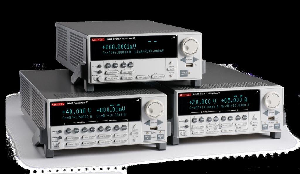
5 Introduction to the Series 2600B System SourceMeter Instrument The Keithley Instruments Series 2600B System SourceMeter Instruments are medium-power source-measure units (SMUs) that simplify test processes by combining source and measure capabilities in a single instrument. A Series 2600B SourceMeter Instrument is a scalable, high-throughput, cost-effective solution for precision DC, pulse, and low-frequency AC source-measure testing. The Series 2600B documentation includes: Quick Start Guide: Shows you how to unpack and set up the instrument to determine that the instrument is functional. Reference Manual: Provides comprehensive information about the instrument s features, operation, optimization, maintenance, troubleshooting, and programming commands. The documentation is in PDF format on the CD-ROM that is included with the instrument. If you do not have Adobe Reader to view the files, you can download a free copy of it at CD-ROM contents The CD-ROMs that are included with your instrument contain: The Test Script Builder (TSB) Software and Series 2600B TSB add-in, which is a software tool you can use to create, modify, debug, and store Test Script Processor (TSP ) test scripts Product documentation in PDF format, including the Quick Start Guide, Reference Manual, product specifications, and rack-mount kit instructions IVI instrument driver and related release notes National Instruments LabVIEW driver and related release notes Java SE Runtime Environment Keithley I/O layer and release notes For the latest drivers and additional support information, see

6 Unpack and inspect the instrument To unpack and inspect the instrument: 1. Inspect the box for damage. 2. Open the top of the box.

7 3. Remove the bag that contains the documentation, accessories, and CD-ROMs. 4. Carefully lift the instrument out of the box. 5. Remove the packaging insert. 6. Inspect the instrument for any obvious signs of physical damage. Report any damage to the shipping agent immediately.

8 In addition to the Series 2600B System SourceMeter Instrument, you should have received: 1 Series 2600B Product Information and Test Script Builder CD-ROMs 2 UL safety supplement 3 Keithley USB flash drive containing the Model 2400 software emulation personality script 4 Interlock DB-25 male connector kit hardware 5 One RJ-45 LAN crossover cable for the Model 2604B. Two RJ-45 LAN crossover cables for the Models 2601B and 2602B 6 Power line cord 7 One 8-pin screw terminal connector for the Model 2601B. Two 8-Pin screw terminal connectors for the Models 2602B and 2604B 8 Safety Standards Conformance Information 9 Models 2601B, 2602B, and 2604B System SourceMeter Instruments Quick Start Guide Refer to the packing list for additional items that might have shipped with your instrument.
9 Connect the instrument Important test system safety information This product is sold as a stand-alone instrument that may become part of a system that could contain hazardous voltages and energy sources. It is the responsibility of the test system designer, integrator, installer, maintenance personnel, and service personnel to make sure the system is safe during use and is operating properly. You must also realize that in many test systems a single fault, such as a software error, may output hazardous signal levels even when the system indicates that there is no hazard present. It is important that you consider the following factors in your system design and use: The international safety standard UL defines voltages as hazardous if they exceed 30 V RMS and 42.4 V peak, or 60 V DC for equipment rated for dry locations. Keithley Instruments, Inc. products are only rated for dry locations. Read and comply with the specifications of all instruments in the system. The overall allowed signal levels may be constrained by the lowest rated instrument in the system. For example, if you are using a 500 V DC power supply with a 300 V DC rated switch, the maximum allowed voltage in the system is 300 V DC. Make sure any test fixture connected to the system protects the operator from contact with hazardous voltages, hot surfaces, and sharp objects. Use shields, barriers, insulation, safety interlocks, and so on to accomplish this. Cover the device under test (DUT) to protect the operator from flying debris in the event of a system or DUT failure. Double-insulate all electrical connections that an operator can touch. Double insulation ensures that the operator is still protected even if one insulation layer fails. Refer to IEC for specific requirements. Make sure all connections are behind a locked cabinet door or other barrier. This protects the system operator from accidentally removing a connection by hand and exposing hazardous voltages.
10 Use high-reliability fail-safe interlock switches to disconnect power sources when a test fixture cover is opened. Where possible, use automatic handlers so operators are not required to access the DUT or other potentially hazardous areas. Provide training to all users of the system so they understand all potential hazards and know how to protect themselves from injury. In many systems, during power up, the outputs may be in an unknown state until they are properly initialized. Make sure the design can tolerate this situation without causing operator injury or hardware damage. To keep users safe, always read and follow all safety warnings provided with each of the instruments in your system. Install the instrument The Series 2600B can be used on a bench or in a rack. Please see the instructions that came with your rack-mount kit if you are installing the Series 2600B in a rack. Note that the air intakes for the fan are located on the top cover and side panels of the Series 2600B. The space around these areas should be free from obstruction to ensure proper fan operation. Connect line power The Series 2600B operates from a line voltage of 100 V to 240 V at a frequency of 50 Hz or 60 Hz. Line voltage is automatically sensed (there are no switches to set). Make sure the operating voltage in your area is compatible. The power cord supplied with the Series 2600B contains a separate ground wire for use with grounded outlets. When proper connections are made, the instrument chassis is connected to power line ground through the ground wire in the power cord. Failure to use a grounded outlet may result in personal injury or death due to electric shock.

 position. 2.")
11 3. Connect the plug of the power cord to a grounded AC outlet. Operating the instrument on an incorrect line voltage may cause damage to the instrument, possibly voiding the warranty. To connect line power: 1. Make sure the front panel power switch is in the off (0) position. Turn on the instrument Turn on the instrument by pressing the front panel POWER switch to the on ( ) position. 2. Connect the socket of the supplied power cord to the power connection on the rear panel.

12 Power-up sequence When the instrument is turned on, you should see: A series of dots. All segments of the display light. A brief display showing the instrument model. For example, if the instrument is a Model 2602B, the display will show KEITHLEY Model 2602B. Line frequency detection and other startup checks. The entire power-up process takes approximately 30 seconds to complete. When initialization is complete, if the instrument is a Model 2602B or a Model 2604B, you will see the default display screen, shown below. If the instrument is a Model 2601B, you will see the default display screen, shown below.
 for this test.")
13 Test the instrument The following test verifies basic operation of the Model 2601B, Model 2602B, and Model 2604B. In this test, you will use the front-panel controls shown below to source voltage and measure the voltage output. You do not need to connect a device under test (DUT) for this test. Step 1: Set source function, range, and level If the instrument has two channels (Models 2602B or 2604B) and is in dual-channel display mode, press the DISPLAY button once to show only the settings for SMU channel A. 1. Press the SRC key. You will see a blinking character in the SrcA value field. Confirm that mv is displayed; if not, press the SRC key again. 2. While that character is still blinking, press the up or down RANGE keys until 40 V is displayed.

14 The main display screen reappears: 3. Press the CURSOR keys to move the cursor to the 10s digit. 4. Press the navigation wheel to enter EDIT mode. The EDIT indicator appears in the upper left corner of the display. 5. Turn the navigation wheel to set the source value to V, and then press the navigation wheel to enter the selection and exit EDIT mode. Step 2: Set the source limit 1. Press the LIMIT key. You will see a blinking character in the LimA value field. 2. While that character is still blinking, press the down RANGE keys as needed to select the 10 ma limit range. Verify that the source limit value in the LimA field is ma.


 or (Model 2601B).")
15 Step 3: Set measurement function and range 1. Press the MEAS key as many times as needed to select the V (voltage) measurement function. In the following figure, the measurement function has been set to V. 2. Press the AUTO key as many times as needed to select the AUTO range function. When AUTO is selected, the Series 2600B automatically selects the best range for the measured value. You will briefly see the display shown below, and then the main display screen reappears. Step 4: Turn the output on Turn the output on by pressing the OUTPUT ON/OFF control (for Model 2602B and 2604B) or (Model 2601B). The ON/OFF indicator LED lights and measurements begin. Step 5: Observe measurements Observe the measured voltage on the main area of front panel display. The readings should be very close to the 20 V source value.
16 Step 6: Turn the output off When you finish making measurements, turn the output off by pressing the OUTPUT ON/OFF or control. The output indicator LED turns off. These steps confirm basic functionality of your Model 2601B, Model 2602B, or Model 2604B instrument. Turn the instrument power OFF now. For a basic understanding of the of the Series 2600B functionality, we strongly recommend that first-time users become familiar with the Series 2600B Reference Manual.
17 FAQs What should I do if I see an error message when I turn the instrument on? If an error message is displayed, press the EXIT (LOCAL) key. The Series 2600B will return to the default display screen. For detailed information about error messages, see Errors and status messages in the Series 2600B Reference Manual. How do I use the included USB flash drive? The USB flash drive included with the Series 2600B can be used to load test scripts onto the instrument from the front panel. The included USB flash drive contains a copy of the Model 2400 personality script, which allows the Series 2600B instrument to accept Model 2400 SCPI commands. For more information about loading and running the 2400 personality script, see Model 2400 emulation in the Series 2600B Reference Manual. What do I do if I lost or formatted the included USB flash drive? How can I get another copy of the Model 2400 personality script? If you lose or format the USB drive or delete the 2400 personality script, you can download the latest version of it from the Keithley Instruments website at Next steps Series 2600B Reference Manual Refer to the Series 2600B Reference Manual for detailed information about all features of the instrument. This manual is on the Product Information CD-ROM that came with your instrument. Keithley Instruments website See for support and additional information about the instrument.
18
Model 8020-KHV. Kelvin Keithley Triaxial Connector Card. Description / October 2014 *P * 1
 Keithley Instruments 28775 Aurora Road Cleveland, Ohio 44139 1-800-935-5595 http://www.keithley.com Model 8020-KHV Kelvin Keithley Triaxial Connector Card Description The Model 8020-KHV Keithley HV Connector
Model 2460-KIT. Screw Terminal Connector Kit. Description / September 2014 *P * 1
 Keithley Instruments 28775 Aurora Road Cleveland, Ohio 44139 1-800-935-5595 http://www.keithley.com Model 2460-KIT Screw Terminal Connector Kit Description The Model 2460-KIT Screw Terminal Connector Kit
Model 2657A-LIM-3 LO Interconnect Module
 Keithley Instruments, Inc. 28775 Aurora Road Cleveland, Ohio 44139 1-888-KEITHLEY http://www.keithley.com Model 2657A-LIM-3 LO Interconnect Module User's Guide Description The Model 2657A-LIM-3 LO Interconnect
Model 8020-STC. Kelvin Standard Triaxial Connector Card. Description / October 2014 *P * 1
 Keithley Instruments 28775 Aurora Road Cleveland, Ohio 44139 1-800-935-5595 http://www.keithley.com Model 8020-STC Kelvin Standard Triaxial Connector Card Description The Model 8020-STC Kelvin Standard
Model 8010 High Power Device Test Fixture Interconnection Reference Guide
 Model 8010 High Power Device Test Fixture Interconnection Reference Guide Safety precautions Observe the following safety precautions before using this product and any associated instrumentation. Although
Model 2600B-PM V Protection Module with 1 A Clamp. Description / April 2015 *PPA * 1
 Keithley Instruments 28775 Aurora Road Cleveland, Ohio 44139 1-800-935-5595 http://www.keithley.com Model 2600B-PM-1 200 V Protection Module with 1 A Clamp Description The Model 2600B-PM-1 200 V Protection
This 4200-RM Rack Mount Kit is for installation in 4200-CAB series cabinets only.
 Keithley Instruments, Inc. 28775 Aurora Road Cleveland, Ohio 44139 (440) 248-0400 Fax: (440) 248-6168 www.keithley.com Model 4200-RM Rack Mount Kit Packing List Introduction NOTE This 4200-RM Rack Mount
Series 370 S SoftwSystem are Qui Switch/Mult ck Start G imeter uide Quick Start Guide
 Series ACS 3700A Software System Quick Switch/Multimeter Start Guide Quick Start Guide Safety precautions Observe the following safety precautions before using this product and any associated instrumentation.
Models 2634B, 2635B, and 2636B System SourceMeter Instruments Quick Start Guide
 Models 2634B, 2635B, and 2636B System SourceMeter Instruments Quick Start Guide Safety Introduction Safety precautions The following safety precautions should be observed before using this product and
CVU-3K-KIT. 3 kv Bias Tee Kit. Description. Parts list / October 2014 *P * 1
 Keithley Instruments 28775 Aurora Road Cleveland, Ohio 44139 1-800-935-5595 http://www.keithley.com CVU-3K-KIT 3 kv Bias Tee Kit Description The CVU-3K-KIT Bias Tee Kit consists of three bias tees for
CVU-200-KIT. 200 V Bias Tee Kit. Description. Parts list / October 2014 *P A* 1
 Keithley Instruments 28775 Aurora Road Cleveland, Ohio 44139 1-800-935-5595 http://www.keithley.com CVU-200-KIT 200 V Bias Tee Kit Description The CVU-200-KIT Bias Tee Kit consists of three 2600-RBT-200
Model 7705 Control Module
 www.keithley.com Model 7705 Control Module User s Guide PA-696 Rev. D / October 2006 A G R E A T E R M E A S U R E O F C O N F I D E N C E Safety Precautions The following safety precautions should be
Models 2601B, 2602B, and 2604B System SourceMeter Instruments Quick Start Guide
 Models 2601B, 2602B, and 2604B System SourceMeter Instruments Quick Start Guide Safety precautions The following safety precautions should be observed before using this product and any associated instrumentation.
HV-CS kv Edge Mount Triaxial Jack
 Keithley Instruments 28775 Aurora Road Cleveland, Ohio 44139 1-800-935-5595 http://www.tek.com/keithley HV-CS-1589 3 kv Edge Mount Triaxial Jack Installation Information Description The Keithley Instruments
Startup Software Quick Start Guide
 Startup Software Quick Start Guide Safety precautions Observe the following safety precautions before using this product and any associated instrumentation. Although some instruments and accessories would
Model 2380 Rack-Mount Kit
 Keithley Instruments 28775 Aurora Road Cleveland, Ohio 44139 1-800-935-5595 http://www.tek.com/keithley Model 2380 Rack-Mount Kit Installation Instructions Introduction The Model 2380 Fixed Rack-Mount
2260B-RMK-Series Rack Mount Kit
 Keithley Instruments, Inc. 28775 Aurora Road Cleveland, Ohio 44139 1-888-KEITHLEY http://www.keithley.com Assembly and Mounting Instructions Introduction The 2260B-RMK-Series Rack Mount Kit is suited for
Model 2380 Rack-Mount Kit
 Keithley Instruments 28775 Aurora Road Cleveland, Ohio 44139 1-800-935-5595 http://www.tek.com/keithley Model 2380 Rack-Mount Kit Installation Instructions Introduction The Model 2380 Fixed Rack-Mount
Model 4200-CVU-PWR. Parts Package. Introduction. PA-977 Rev. C / September 2016 *PPA-977C* 1
 Keithley Instruments 28775 Aurora Road Cleveland, Ohio 44139 1-800-935-5595 http://www.tek.com/keithley Model 4200-CVU-PWR Parts Package Introduction The Model 4200-CVU-PWR C-V Power Package for both the
Safety Precautions A good safety practice is to expect that hazardous voltage is present in any unknown circuit before measuring.
 Safety Precautions The following safety precautions should be observed before using this product and any associated instrumentation. Although some instruments and accessories would normally be used with
Model GHz 50 Ohm RF Module
 Keithley Instruments 28775 Aurora Road Cleveland, Ohio 44139 1-800-935-5595 tek.com/keithley Model 7711 2 GHz 50 Ohm RF Module Instructions for use with DAQ6510 Introduction The 7711 plug-in module provides
Models 707B and 708B Switching Matrix
 E C N E D I F N O C F O E R U S A E M R E T A E R G A Models 707B and 708B Switching Matrix User s Manual 707B-900-01 Rev. A / August 2010 Test Equipment Depot - 800.517.8431-99 Washington Street Melrose,
Series 2600A System SourceMeter
 www.keithley.com Series 2600A System SourceMeter Quick Start Guide 2600AS-903-01 Rev. A / September 2008 A G R E A T E R M E A S U R E O F C O N F I D E N C E WARRANTY Keithley Instruments, Inc. warrants
Model 7701 Multiplexer Module
 Keithley Instruments 28775 Aurora Road Cleveland, Ohio 44139 1-800-935-5595 tek.com/keithley Model 7701 Multiplexer Module Instructions for use with DAQ6510 Introduction The 7701 32-Channel High-Speed
2281S Precision DC Supply and Battery Simulator Quick Start Guide
 2281S Precision DC Supply and Battery Simulator Quick Start Guide Safety precautions Observe the following safety precautions before using this product and any associated instrumentation. Although some
Keithley Instruments Customer Documentation Series 2600A UL Safety Supplement
 Keithley Instruments, Inc. 28775 Aurora Road Cleveland, Ohio 44139 1-888-KEITHLEY www.keithley.com Keithley Instruments Customer Documentation Series 2600A UL Safety Supplement 1. Introduction The Keithley
Model Channel High Voltage Multiplexer Card
 User s Manual 3762-900-01 Rev. A / July 2017 www.tek.com/keithley Model 3762 10-Channel High Voltage Multiplexer Card *P3762-900-01A* 3762-900-01A Model 3762 10-Channel High Voltage Multiplexer Card User's
Model 2440 Service Manual Rev. B / December 2004
 www.keithley.com Model 2440 Service Manual 2440-902-01 Rev. B / December 2004 A G R E A T E R M E A S U R E O F C O N F I D E N C E WARRANTY Keithley Instruments, Inc. warrants this product to be free
Model DAQ6510 Quick Start Guide
 Model DAQ6510 Quick Start Guide Safety precautions The following safety precautions should be observed before using this product and any associated instrumentation. Although some instruments and accessories
Model 7700 Multiplexer Module
 Keithley Instruments 28775 Aurora Road Cleveland, Ohio 44139 1-800-935-5595 tek.com/keithley Model 7700 Multiplexer Module Instructions for use with DAQ6510 Introduction The 7700 20-Channel Differential
S530 Parametric Test System
 www.tek.com/keithley S530 Parametric Test System Diagnostic and Verification Manual S530-906-01 Rev. F / September 2017 *PS530-906-01G* S530-906-01G A Tektronix Company S530 Diagnostic and Verification
Model 2450 Interactive SourceMeter Instrument
 Model 2450 Interactive SourceMeter Instrument Calibration Manual 2450-905-01 Rev. A / June 2014 www.keithley.com *P245090501A* 2450-905-01 A Greater Measure Of Confidence A Tektr onix Company Model 2450
Model kw Pulse Mode Interactive
 Model 2461 1 kw Pulse Mode Interactive SourceMeter Instrument User s Manual 2461-900-01 Rev. A / November 2015 Test Equipment Depot - 800.517.8431-99 Washington Street Melrose, MA 02176 - TestEquipmentDepot.com
Series 3700 System Switch/Multimeter
 www.keithley.com Series 3700 System Switch/Multimeter Quick Start Guide 3700S-903-01 Rev. C / November 2008 A G R E A T E R M E A S U R E O F C O N F I D E N C E WARRANTY Keithley Instruments, Inc. warrants
Model DAQ6510 Data Acquisition and Multimeter System
 User s Manual DAQ6510-900-01 Rev. A / April 2018 tek.com/keithley Model DAQ6510 Data Acquisition and Multimeter System *PDAQ6510-900-01A* DAQ6510-900-01A DAQ6510 Data Acquisition / Multimeter System User's
Model 2701 Ethernet-Based DMM / Data Acquisition System
 www.keithley.com Model 2701 Ethernet-Based DMM / Data Acquisition System Instrument Networking Instruction Manual 2701-904-01 Rev. C / October 2008 A G R E A T E R M E A S U R E O F C O N F I D E N C E
KPXI 3U Instrument Chassis
 www.keithley.com KPXI 3U Instrument Chassis User s Manual KPXI-SYS-900-01 Rev. A / January 2007 A G R E A T E R M E A S U R E O F C O N F I D E N C E WARRANTY Keithley Instruments, Inc. warrants this product
Model 8101-PIV Test Fixture User s Guide. Overview. SMU Device holder (near latch) Two Leaded Part Plungers. PIV Device holder (near hinge)
 Two Leaded Part Plungers. PIV Device holder (near hinge)") Keithley Instruments, Inc. 28775 Aurora Road Cleveland, Ohio 44139 1-888-KEITHLEY www.keithley.com Model 8101-PIV Test Fixture User s uide Overview WARNIN The procedures contained in this User s uide are
Keithley Instruments, Inc. 28775 Aurora Road Cleveland, Ohio 44139 1-888-KEITHLEY www.keithley.com Model 8101-PIV Test Fixture User s uide Overview WARNIN The procedures contained in this User s uide are
Model 2700 Multimeter/Data Acquisition System Service Manual
 Model 2700 Multimeter/Data Acquisition System Service Manual 2015, Keithley Instruments All rights reserved. Cleveland, Ohio, U.S.A. Third Printing, August 2015 Document Number: 2700-902-01 Rev. C Manual
User Manual. 400Amp AC Clamp Meter + NCV. Model MA430. Additional User Manual Translations available at
 User Manual 400Amp AC Clamp Meter + NCV Model MA430 Additional User Manual Translations available at www.extech.com Introduction Congratulations on your purchase of this Extech MA430 Clamp Meter. This
Model /2-Digit Resolution Digital Multimeter
 www.keithley.com Model 2100 6 1/2-Digit Resolution Digital Multimeter User s Manual 2100-900-01 Rev. D / September 2011 A G R E A T E R M E A S U R E O F C O N F I D E N C E Model 2100 6 ½-Digit Resolution
ETHOS Auto Ranging Digital Multimeter
 ETHOS 5020 Auto Ranging Digital Multimeter 1 1. SAFETY INFORMATION SAFETY SYMBOLS Warning! Dangerous Voltage (Risk of electric shock). Caution! Refer to the user s manual before using this Meter. Double
Model P4017 Single Channel USB Oscilloscope. Quick Start Guide
 Model P4017 Single Channel USB Oscilloscope Quick Start Guide General Warranty BNC warrants that the product will be free from defects in materials and workmanship for 3 years from the date of purchase
DM-918 OPERATIONS MANUAL AUTORANGING MULTIMETER
 DM-918 OPERATIONS MANUAL AUTORANGING MULTIMETER SAFETY INFORMATION The following safety information must be observed to ensure maximum personal safety during the operation of this meter: This meter is
374 FC/375 FC/376 FC. Clamp Meter. Safety Information
 374 FC/375 FC/376 FC Clamp Meter Safety Information 3-Year Limited Warranty. Go to www.fluke.com to register your Product, read the Users Manual, and find more information. A Warning identifies conditions
Model 2000-SCAN Scanner Card
 www.keithley.com Model 2000-SCAN Scanner Card Instruction Manual 2000-SCAN-901-01 Rev. F / February 2014 *P2000SCAN90101F* 2000-SCAN-901-01F A Greater Measure of Confidence Model 2000-SCAN Scanner Card
User Guide True RMS Multimeter Extech EX205T
 User Guide Extech EX205T True RMS Digital Multimeter Extech EX210T True RMS Digital Multimeter IR True RMS Multimeter Extech EX205T Introduction Thank you for selecting the Extech EX205T True RMS Auto-ranging
9040/9040UK. Users Manual. Phase Rotation Indicator
 9040/9040UK Phase Rotation Indicator Users Manual PN 2438546 April 2005 2005 Fluke Corporation. All rights reserved. Printed in China All product names are trademarks of their respective companies. LIMITED
BS 287 DUAL CHANNEL POWER SUPPLY. User Manual. January 2017 V1.0
 BS 287 DUAL CHANNEL POWER SUPPLY User Manual January 2017 V1.0 Table of contents 1.0 SAFETY INSTRUCTIONS... 3 2.0 GENERAL DESCRIPTION PS 289... 4 3.0 MECHANICAL INSTALLATION... 5 4.0 MAINS POWER & SAFETY
1-36V, 0-3A DC Power Supply
 1550 1-36V, 0-3A DC Power Supply User Manual Safety Summary The following safety precautions apply to both operating and maintenance personnel and must be followed during all phases of operation, service,
PCT2000. User Manual. Precision current transducer 2000 A
 PCT2000 User Manual PCT2000 Precision current transducer 2000 A User Manual Status: November 6, 2018 Copyright 2018 ZES ZIMMER Electronic Systems GmbH Pfeiffstraße 12 61440 Oberursel (Taunus), Germany
Installing and Configuring Rialto Analytic Appliances
 Installing and Configuring Rialto Analytic Appliances Important Safety Information This manual provides installation and operation information and precautions for the use of this camera. Incorrect installation
OPERATING INSTRUCTION
 OPERATING INSTRUCTION AUTORANGING MULTIMETER MAX Ω F C 10A MAX every 15 min. COM V SAFETY INFORMATION The following safety information must be observed to insure maximum personal safety during the operation
Emerson Network Power provides customers with technical support. Users may contact the nearest Emerson local sales office or service center.
 Liebert PSA iton User Manual Version: V2.8 Revision date: November 14, 2005 Emerson Network Power provides customers with technical support. Users may contact the nearest Emerson local sales office or
99 Washington Street Melrose, MA Phone Toll Free Visit us at
 99 Washington Street Melrose, MA 02176 Phone 781-665-1400 Toll Free 1-800-517-8431 Visit us at www.testequipmentdepot.com Table of Contents 1. General Safety Requirements... 1 2. Safety Terms and Symbols...
Part No. Z , IA Nov OPERATION MANUAL. High Voltage Digitalmeter A
 Part No. Z1-109-920, IA001723 Nov. 2005 OPERATION MANUAL High Voltage Digitalmeter 149-30A Use of Operation Manual Please read through and understand this Operation Manual before operating the product.
Digital ac/dc (24V) Input Module
 Input Module") Installation Instructions Digital ac/dc (24V) Input Module Catalog Number 1771-IND, Series C Topic Page Important User Information 2 Before You Begin 3 Power Requirements 3 Prevent Electrostatic Discharge
Installation Instructions Digital ac/dc (24V) Input Module Catalog Number 1771-IND, Series C Topic Page Important User Information 2 Before You Begin 3 Power Requirements 3 Prevent Electrostatic Discharge
Allworx 24x Service and Troubleshooting Guide
 Allworx 24x Service and Troubleshooting Guide -PAGE INTENTIALLY LEFT BLANK- Table of Contents 1 Safety Instructions...1 1.1 Electrical...1 1.2 Electrostatic Discharge...1 2 Chassis Views...2 3 Exterior
Model 2001 Multimeter
 www.keithley.com Model 2001 Multimeter Calibration Manual 2001-905-01 Rev. G / May 2004 A G R E A T E R M E A S U R E O F C O N F I D E N C E Model 2001 Multimeter Calibration Manual 1992, Keithley Instruments,
TH2683 Insulation Resistance Meter. User s Mannual
 TH2683 Insulation Resistance Meter User s Mannual 1 CONTENTS Chapter 1 Genernal Information... 3 1.1 Feature Overview... 3 1.2 Operating Environment... 3 1.3 Dimensions and Weight... 3 1.4 Unpacking Inspection...
Autoranging True RMS Multimeter User Manual
 Autoranging True RMS Multimeter User Manual Please read this manual before switching the unit on. Important safety information inside. Contents Page 1. Safety Information... 4 2. Safety Symbols... 5 3.
OPERATING MANUAL FOR THE 30KV A.C. TEST SET P123. Bicotest High Voltage Products Ltd
 OPERATING MANUAL FOR THE 30KV A.C. TEST SET P123 Product: High Voltage AC Test Set Type: P123 Bicotest High Voltage Products Ltd Hellesdon Park Road, Drayton High Road, Norwich NR6 5DR United Kingdom Phone
ATK-2040 AC/DC TRMS Watt Clamp Meter Users Manual
 ATK-2040 AC/DC TRMS Watt Clamp Meter Users Manual EN 61010-2-032 CAT II 600V, CAT III 300V Pollution Degree 2 SYMBOLS showed on the clamp meter or in this manual: Caution, risk of danger. Refer to accompanying
EPS Power Supply
 EPS - 600 Power Supply Installation and Operation Manual Version 1.0 *This instrument is intended for laboratory use only Index A. Important Notice ----------------------------------------------------------------
General Warranty. For more details, please refer to the user manual on the supplied CD, it can also be downloaded at
 General Warranty Lilliput warrants that the product will be free from defects in materials and workmanship for a period of 3 years (1 year for accessories) from the date of purchase of the product by the
Part No. Z , IA Jul OPERATION MANUAL. High Voltage Digitalmeter A
 Part No. Z1-109-820, IA001705 Jul. 2016 OPERATION MANUAL High Voltage Digitalmeter 149-10A Use of Operation Manual Please read through and understand this Operation Manual before operating the product.
Series 2200 Programmable DC Power Supplies
 www.keithley.com Series 2200 Programmable DC Power Supplies Reference Manual 2200S-901-01 Rev. A / November 2011 A G R E A T E R M E A S U R E O F C O N F I D E N C E Series 2200 Programmable DC Power
DS1000B Series Digital Oscilloscope
 Quick Guide RIGOL Publication number QGA04114-1110 Feb. 2014 DS1000B Series Digital Oscilloscope DS1074B, DS1104B, DS1204B All Rights Reserved Copyright All Rights Reserved. RIGOL products are protected
Owner's Manual. True RMS Multimeter. Model No Safety Operation Maintenance Español
 Owner's Manual True RMS Multimeter Model No. 82023 CAUTION: Read, understand and follow Safety Rules and Operating Instructions in this manual before using this product. Safety Operation Maintenance Español
Part No. Z , IA Mar OPERATION MANUAL. High Voltage Digitalmeter A
 Part No. Z1-109-820, IA001704 Mar. 2011 OPERATION MANUAL High Voltage Digitalmeter 149-10A Use of Operation Manual Please read through and understand this Operation Manual before operating the product.
AutoRanging Digital MultiMeter
 Owner's Manual AutoRanging Digital MultiMeter Model No. 82175 CAUTION: Read, understand and follow Safety Rules and Operating Instructions in this manual before using this product. Safety Operation Maintenance
POCKET MULTIMETER Model No: MM18
 INSTRUCTIONS FOR: POCKET MULTIMETER Model No: MM18 Thank you for purchasing a Sealey product. Manufactured to a high standard this product will, if used according to these instructions and properly maintained,
Mini Digital Multimeter
 User Manual Mini Digital Multimeter Model MN15A Additional User Manual Translations available at www.extech.com Introduction Congratulations on your purchase of the Extech MN15A MultiMeter. The MN15A offers
Obtaining Documentation and Submitting a Service Request, page xvii Safety Warnings, page xvii Safety Guidelines, page xx
 Preface Obtaining Documentation and Submitting a Service Request, page xvii Safety s, page xvii Safety Guidelines, page xx Obtaining Documentation and Submitting a Service Request For information on obtaining
Operation Manual. Concorde 600 Power Supply. *This instrument is intended for laboratory use only.
 Concorde 600 Power Supply Operation Manual Cat.no. R10-1001011 *This instrument is intended for laboratory use only http://www.recenttec.com E-mail : support@recenttec.com Version 1.1 Packing List x 1
2016 SIGLENT TECHNOLOGIES CO.,LTD
 Quick Strat SDM3045X Digital Multimeter QS06034-E01A 2016 SIGLENT TECHNOLOGIES CO.,LTD Copyright Information SIGLENT TECHNOLOGIES CO., LTD. All rights reserved. The information provided in this manual
BS 181 SINGLE CHANNEL POWER SUPPLY USER MANUAL
 BS 181 SINGLE CHANNEL POWER SUPPLY USER MANUAL Issue 2011 ASL Intercom BV DESIGNED & MANUFACTURED BY: ASL Intercom B.V. Zonnebaan 42 3542 EG Utrecht The Netherlands Tel: +31 (0)30 2411901 Fax: +31 (0)30
Series 2200 Multichannel Programmable DC Power Supplies User Manual
 www.keithley.com Series 2200 Multichannel Programmable DC Power Supplies User Manual 2220S-900-01 Rev. B / October 2012 A G R E A T E R M E A S U R E O F C O N F I D E N C E Series 2200 Multichannel Programmable
TOT Series Manual. North American and International Models - without optional faceplate. Receptacle Panel of International Models, CE model shown
 TOT Series Manual North American and International Models - without optional faceplate Receptacle Panel of International Models, CE model shown North American Models Table of Content 1. Important Safety
MODEL 805 USER MANUAL
 MODEL 805 USER MANUAL All Rights Reserved Page 1 of 12 UNPACKING & INSPECTION Save all packing materials they are required for returns and warranty service. Inspect the 805 and packing materials for any
LVN5200A-R2, rev. 1, Hardware Installation Guide
 LVN5200A-R2 LVN5250A-R2 LVN5200A-R2, rev. 1, Hardware Installation Guide Customer Support Information Order toll-free in the U.S.: Call 877-877-BBOX (outside U.S. call 724-746-5500) FREE technical support
Preparing to Install the VG248
 CHAPTER 2 To ensure normal system operation, plan your site configuration and prepare your site before installation. Before installing the VG248, review these sections: Preparing the Installation Site,
OWNER S MANUAL CD-2 V 1.3
 OWNER S MANUAL CD-2 V 1.3 2 TABLE OF CONTENTS WARNINGS... 3 ACCESSORIES... 4 REMOTE CONTROL... 5 FRONT PANEL... 6 REAR PANEL... 7 MENU SYSTEM... 8 NOTES OF IMPORTANCE... 10 CONNECTORS... 11 TECHNICAL SPECIFICATIONS...
NI PXIe-1062Q Power Supply Shuttle
 USER GUIDE NI PXIe-1062Q Power Supply Shuttle The NI PXIe-1062Q power supply shuttle is a replacement part for the NI PXIe-1062Q chassis. Caution This power supply is not compatible with any other National
Series Watt DC Power Supplies
 Keithley Instruments 28775 Aurora Road Cleveland, Ohio 44139 1-800-935-5595 http://www.keithley.com Series 2268 850-Watt DC Power Supplies Specifications SPECIFICATION CONDITIONS This document contains
DM3058/DM3058E Digital Multimeter
 Quick Guide RIGOL Publication number QGA03109-1110 Feb. 2014 DM3058/DM3058E Digital Multimeter 2008 RIGOL Technologies, Inc. All Rights Reserved Copyright 2008 RIGOL Technologies, Inc. All Rights Reserved.
PCT200. User Manual. Precision current transducer 200 A
 PCT200 User Manual PCT200 Precision current transducer 200 A User Manual Status: November 6, 2018 Copyright 2018 ZES ZIMMER Electronic Systems GmbH Pfeiffstraße 12 61440 Oberursel (Taunus), Germany phone
Model INSTRUCTION MANUAL DIGITAL MULTIMETER
 Model 57040 INSTRUCTION MANUAL DIGITAL MULTIMETER SAFETY INFORMATION This multimeter has been designed according to IEC 1010 concerning electronic measuring instruments with an overvoltage category (CAT
General Warranty. For more details, please refer to the user manual on the supplied CD, it can also be downloaded at
 General Warranty OWON warrants that the product will be free from defects in materials and workmanship for a period of 3 years (1 year for accessories) from the date of purchase of the product by the original
4170 POS System Installation Guide
 4170 POS System 4170 Installation Guide Thank you for selecting UTC RETAIL s innovative Model 4170 Point of Sale solution! This Installation Guide will help you efficiently install the 4170 POS. The document
User's Guide. 800 Amp Clamp Meters. EX710 AC Clamp meter EX720 True RMS AC Clamp meter EX730 AC/DC True RMS Clamp meter
 User's Guide 800 Amp Clamp Meters EX710 AC Clamp meter EX720 True RMS AC Clamp meter EX730 AC/DC True RMS Clamp meter Introduction Congratulations on your purchase of the EX710, EX720, or EX730 Clamp DMM.
TOT Series Manual. North American CE and UK Models. CE Models. UK Models. North American Models
 TOT Series Manual North American CE and UK Models CE Models UK Models North American Models Table of Content 1. Important Safety Instructions 2. Description Shipping Carton & Packing Material Placement
USER MANUAL. Mini Multimeter with Non-Contact Voltage Detector (NCV) Model EX310
 Model EX310") USER MANUAL Mini Multimeter with Non-Contact Voltage Detector (NCV) Model EX310 Introduction Congratulations on your purchase of the Extech EX310 MultiMeter. The EX310 offers AC/DC Voltage, AC/DC Current,
USER MANUAL Mini Multimeter with Non-Contact Voltage Detector (NCV) Model EX310 Introduction Congratulations on your purchase of the Extech EX310 MultiMeter. The EX310 offers AC/DC Voltage, AC/DC Current,
Operating instructions. Switching amplifier DN0210 DN / / 2015
 Operating instructions Switching amplifier DN0210 DN0220 UK 80011079 / 00 01 / 2015 Contents 1 Preliminary note...4 1.1 Symbols used...4 1.2 Warning signs used...4 2 Safety instructions...5 2.1 General...5
Model 2010 Multimeter Service Manual Rev. D / October 2003
 www.keithley.com Model 2010 Multimeter Service Manual 2010-902-01 Rev. D / October 2003 A G R E A T E R M E A S U R E O F C O N F I D E N C E WARRANTY Keithley Instruments, Inc. warrants this product to
S-14 S-14. Compact Digital Multimeter. Compact Digital Multimeter
 S-14 Compact Digital Multimeter S-14 Compact Digital Multimeter SAFETY INFORMATION The following safety information must be observed to insure maximum personal safety during the operation at this meter
Model A Mini AC/DC Clamp Meter. User's Guide
 Model 380950 80A Mini AC/DC Clamp Meter User's Guide Introduction Congratulations on your purchase of the Extech 80A Mini AC/DC Clamp Meter. The Model 380950 measures AC/DC Current, AC/DC Voltage, Resistance,
ITA-1711 Series Fanless Compact Embedded IPC with Intel Celeron Dual Core CPU Startup Manual
 ITA-1711 Series Fanless Compact Embedded IPC with Intel Celeron Dual Core CPU Startup Manual Packing List Specifications Before you begin installing your IPC, please make sure that the following items
Mini Digital Multimeter
 User's Guide Mini Digital Multimeter Model MN15 99 Washington Street Melrose, MA 02176 Phone 781-665-1400 Toll Free 1-800-517-8431 Visit us at www.testequipmentdepot.com Back to the Extech MN15/MN16 Series
SATA II HDD Canister KISS DA 435 Quick Reference Guide
 SATA II HDD Canister KISS DA 435 Quick Reference Guide If it s embedded, it s Kontron 1. Table of Contents SATA II HDD Canister KISS DA 435 1. Table of Contents 1. Table of Contents... 1 2. Important Information...