RS485 MODBUS Module 6RO
|
|
|
- William Hoover
- 5 years ago
- Views:
Transcription

1 Version /02/2013 Manufactured for


2 Thank you for choosing our product. This manual will help you with proper support and proper operation of the device. The information contained in this manual have been prepared with utmost care by our professionals and serve as a description of the product without incurring any liability for the purposes of commercial law. This information does not release you from the obligation of own judgment and verification. We reserve the right to change product specifications without notice. Please read the instructions carefully and follow the recommendations contained therein. WARNING! Failure to follow instructions can result in equipment damage or impede the use of the hardware or software. Version /02/ / 15
3 1. Safety rules Before first use, refer to this manual RS485 MODBUS Module 6RO Before first use, make sure that all cables are connected properly Please ensure proper working conditions, according to the device specifications (eg: supply voltage, temperature, maximum power consumption) Before making any modifications to wiring connections, turn off the power supply 2. Module Features 2.1. Purpose and description of the module The 6RO Module is an innovative device that provides a simple and cost-effective extension of the number of lines of output with high current-carrying capacity. The module has 6 relay outputs. Each relay has three terminals: common (COM), normally open (NO) or normally closed (NC), so that the unit is very flexible. This module is connected to the RS485 bus with twisted-pair wire. Communication is via MODBUS RTU or MODBUS ASCII. The use of 32-bit ARM core processor provides fast processing and quick communication. The baud rate is configurable from 2400 to The module is designed for mounting on a DIN rail in accordance with DIN EN The module is equipped with a set of LEDs used to indicate the status of inputs and outputs useful for diagnostic purposes and helping to find errors. Module configuration is done via USB by using a dedicated computer program. You can also change the parameters using the MODBUS protocol. Version /02/ / 15
4 2.2. Technical Specifications Power Supply Outputs Temperature Connectors Size Voltage V DC ± 20% Maximum Current No of outputs 6 The maximum current and voltage (resistive load) Work Storage Power Supply Communication Outputs Quick connector Configuration Height Length Width V / V 5A 250V AC 10A 24V DC -10 C C -40 C C 2 pins 3 pins 2 x 10 pins IDC10 Mini USB 120 mm 101 mm 22,5 mm Interface RS485 Up to 128 devices Version /02/ / 15

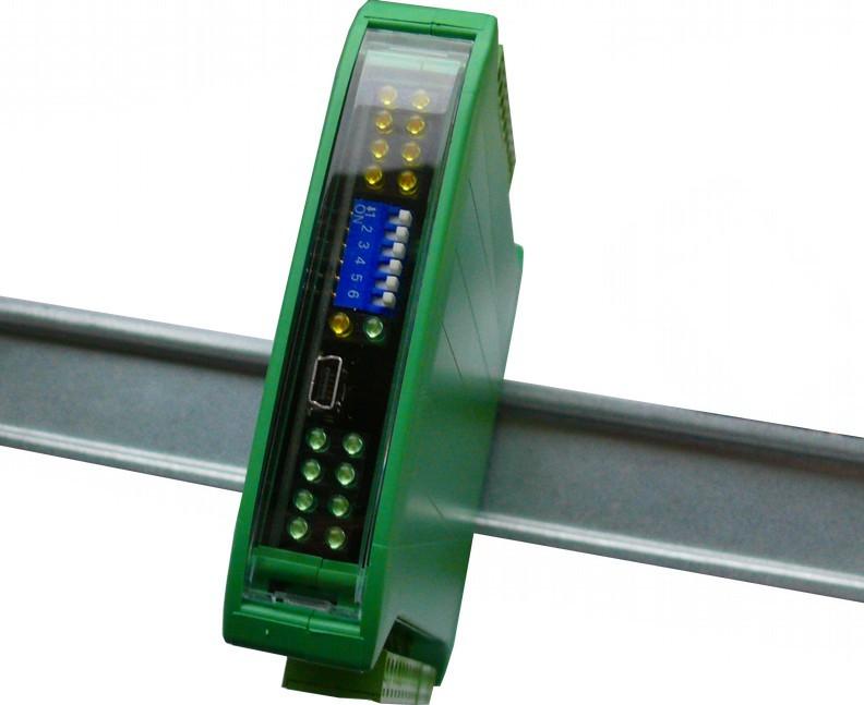
5 2.3. Dimensions of the product RS485 MODBUS Module 6RO Look and dimensions of the module are shown below. The module is mounted directly to the rail in the DIN industry standard. Power connectors, communication and IOs are at the bottom and top of the module. USB connector configuration and indicators located on the front of the module. Version /02/ / 15
6 3. Communication configuration 3.1. Grounding and shielding RS485 MODBUS Module 6RO In most cases, IO modules will be installed in an enclosure along with other devices which generate electromagnetic radiation. Examples of these devices are relays and contactors, transformers, motor controllers etc. This electromagnetic radiation can induce electrical noise into both power and signal lines, as well as direct radiation into the module causing negative effects on the system. Appropriate grounding, shielding and other protective steps should be taken at the installation stage to prevent these effects. These protective steps include control cabinet grounding, module grounding, cable shield grounding, protective elements for electromagnetic switching devices, correct wiring as well as consideration of cable types and their cross sections Network Termination Transmission line effects often present a problem on data communication networks. These problems include reflections and signal attenuation. To eliminate the presence of reflections from the end of the cable, the cable must be terminated at both ends with a resistor across the line equal to its characteristic impedance. Both ends must be terminated since the direction of propagation is bidirectional. In the case of an RS485 twisted pair cable this termination is typically 120 Ω Setting Module Address in RS485 Modbus Network The following table shows how to set switch to determine the address of the module. The module address is set with the switches in the range of 0 to 31. Addresses From 32 to 255 can by set via RS485 or USB. Addr SW5 SW4 SW3 SW2 SW1 0 OFF OFF OFF OFF OFF 1 OFF OFF OFF OFF ON 2 OFF OFF OFF ON OFF 3 OFF OFF OFF ON ON 4 OFF OFF ON OFF OFF 5 OFF OFF ON OFF ON 6 OFF OFF ON ON OFF 7 OFF OFF ON ON ON 8 OFF ON OFF OFF OFF 9 OFF ON OFF OFF ON 10 OFF ON OFF ON OFF Addr SW5 SW4 SW3 SW2 SW1 11 OFF ON OFF ON ON 12 OFF ON ON OFF OFF 13 OFF ON ON OFF ON 14 OFF ON ON ON OFF 15 OFF ON ON ON ON 16 ON OFF OFF OFF OFF 17 ON OFF OFF OFF ON 18 ON OFF OFF ON OFF 19 ON OFF OFF ON ON 20 ON OFF ON OFF OFF 21 ON OFF ON OFF ON Addr SW5 SW4 SW3 SW2 SW1 22 ON OFF ON ON OFF 23 ON OFF ON ON ON 24 ON ON OFF OFF OFF 25 ON ON OFF OFF ON 26 ON ON OFF ON OFF 27 ON ON OFF ON ON 28 ON ON ON OFF OFF 29 ON ON ON OFF ON 30 ON ON ON ON OFF 31 ON ON ON ON ON Version /02/ / 15
7 3.4. Types of Modbus Registers There are 4 types of variables available in the module RS485 MODBUS Module 6RO Type Beginning address Variable Digital Outputs Digital Inputs Input Registers Output Registers Access Bit Read & Write Bit Read Registered Read Registered Read & Write Modbus Command 1, 5, , 6, Communication settings The data stored in the modules memory are in 16-bit registers. Access to registers is via MODBUS RTU or MODBUS ASCII Default settings You can restore the default configuration by the switch SW6 ( see Restore the default configuration) Baud rate Parity Data bits 8 Stop bits 1 Reply Delay [ms] 0 Modbus Mode No RTU Restore the default configuration To restore the default configuration: turn off the power turn on the switch SW6 turn on the power when power and communication LED flash turn off the switch SW6 Caution! After restoring the default configuration all values stored in the registers will be cleared as well. Version /02/ / 15
8 Configuration registers Modbus Dec Hex Address Name x02 Baud rate x04 Parity x03 Stop Bits LSB x03 Data Bits MSB Values other value * 10 0 none 1 odd 2 even 3 always 1 4 always 0 1 one stop bit 2 two stop bits 7 7 data bits 8 8 data bits x05 Response delay Time in ms x06 Modbus Mode 0 RTU 1 ASCII Version /02/ / 15


9 4. Indicators 6 outputs state Power Supply Communication Indicator Description Power supply LED indicates that the module is correctly powered. Communication The LED lights up when the unit received the correct packet and sends the answer. Outputs state LED indicates that the output is on. Version /02/ / 15


10 5. Module Connection Version /02/ / 15

. Version 2.")
11 6. Switches Switch Function Description 1 Module address +1 2 Module address +2 3 Module address +4 4 Module address +8 5 Module address Restoring default settings Setting module address from 0 to 31 Restoring default settings (see Default settings and Restore the default configuration). Version /02/ / 15
12 7. Modules Registers 7.1. Registered access Modbus Dec Hex Register Name Access Description x00 Version/Type Read Version and Type of the device x01 Switches Read Switches state x02 Baud rate Read & Write RS485 baud rate x03 Stop Bits & Data Bits Read & Write No of Stop bits & Data Bits (see 3.5.3) x04 Parity Read & Write Parity bit x05 Response Delay Read & Write Response delay in ms x06 Modbus Mode Read & Write Modbus Mode (ASCII or RTU) x08 Watchdog Read & Write Watchdog x0C Default outputs state Read & Write Default outputs state x20 Received packets MSB Read & Write x21 Received packets LSB Read & Write No of received packets x22 Incorrect packets MSB Read & Write x23 Incorrect packets LSB Read & Write No of received packets with error x24 Sent packets MSB Read & Write x25 Sent packets LSB Read & Write No of sent packets x33 Outputs Read & Write Outputs state Version /02/ / 15
13 7.2. Bit access Modbus Address Dec Address Hex Address Register name Access Description x0C0 Default output 1 state Read & Write Default output 1 state x0C1 Default output 2 state Read & Write Default output 2 state x0C2 Default output 3 state Read & Write Default output 3 state x0C3 Default output 4 state Read & Write Default output 4 state x0C4 Default output 5 state Read & Write Default output 5 state x0C5 Default output 6 state Read & Write Default output 6 state x330 Output 1 Read & Write Output 1 state x331 Output 2 Read & Write Output 2 state x332 Output 3 Read & Write Output 3 state x333 Output 4 Read & Write Output 4 state x334 Output 5 Read & Write Output 5 state x335 Output 6 Read & Write Output 6 state Version /02/ / 15


14 8. Configuration software RS485 MODBUS Module 6RO Modbus Configurator is software that is designed to set the module registers responsible for communication over Modbus network as well as to read and write the current value of other registers of the module. This program can be a convenient way to test the system as well as to observe real-time changes in the registers. Communication with the module is done via the USB cable. The module does not require any drivers. Configurator is a universal program, whereby it is possible to configure all available modules. Version /02/ / 15
15 Table of content 1. Safety rules Module Features Purpose and description of the module Technical Specifications Dimensions of the product Communication configuration Grounding and shielding Network Termination Setting Module Address in RS485 Modbus Network Types of Modbus Registers Communication settings Default settings Restore the default configuration Configuration registers Indicators Module Connection Switches Modules Registers Registered access Bit access Configuration software...14 Version /02/ / 15


16 Manufactured for: Aspar s.c. ul. Kapitańska Gdynia Poland ampero@ampero.eu tel ;
SDM-6RO. Expansion Module 6 relay outputs. Manufactured for
 Version 1.0 5.02.2014 Manufactured for Thank you for choosing our product. This manual will help you with proper support and proper operation of the device. The information contained in this manual have
RS485 MODBUS Module 8AO
 Version 1.3 12/02/2013 Manufactured for Thank you for choosing our product. This manual will help you with proper support and proper operation of the device. The information contained in this manual have
SDM-8AO. Expansion Module 8 analog outputs. Manufactured for
 Version 1.0 16.05.2014 Manufactured for Thank you for choosing our product. This manual will help you with proper support and proper operation of the device. The information contained in this manual have
RS485 MODBUS Module 8I8O
 Expansion Module 8 digital inputs, 8 digital outputs Version 2.2 12/01/2014 Manufactured for Thank you for choosing our product. This manual will help you with proper support and proper operation of the
RS485 MODBUS Module 16I-M
 Version 2.0 12/02/2013 Manufactured for Thank you for choosing our product. This manual will help you with proper support and proper operation of the device. The information contained in this manual have
RS485 MODBUS Module 8I8RO
 Expansion Module 8 digital inputs, 8 relay outputs Version 1.0 3.12.2014 Manufactured for Thank you for choosing our product. This manual will help you with proper support and proper operation of the device.
SDM-8I8O. Expansion Module 8 digital inputs, 8 digital outputs. Manufactured for
 Version 1.2 20.01.2014 Manufactured for Thank you for choosing our product. This manual will help you with proper support and proper operation of the device. The information contained in this manual have
RS 485 Mini Modbus 1AO
 RS 485 Mini Modbus 1AO Version 1.0 14/08/2014 Manufactured for Thank you for choosing our product. This manual will help you with proper support and proper operation of the device. The information contained
RS485 IO Slim Module MOD-ETH
 Expansion Module gateway Modbus TCP Version 1.0 01.12.2015 Manufactured for Thank you for choosing our product. This manual will help you with proper support and proper operation of the device. The information
isma-b-mg-ip User Manual Global Control 5 Sp. z o.o. Poland, Warsaw
 isma-b-mg-ip User Manual Global Control 5 Sp. z o.o. Poland, Warsaw www.gc5.pl Table of content 1 Introduction... 4 1.1 Revision history... 5 1.2 Safety rules... 5 1.3 Technical specifications... 6 1.4
isma-b-fcu FCU Hardware User Manual Global Control 5 Sp. z o.o. Warsaw, Poland
 isma-b-fcu User Manual FCU Hardware Global Control 5 Sp. z o.o. Warsaw, Poland www.gc5.pl Table of contents 1 Introduction 3 1.1 Document change log 3 1.2 Safety rules 3 1.3 Technical specifications 4
NetBiter I/O Extender User Manual
 User Manual Part no. 0920-9999-009 IntelliCom Innovation AB Pilefeltsgatan 73 SE-302 50 Halmstad SWEDEN Phone +46 35 17 29 90 Fax +46 35 17 29 09 email info@intellicom.se www www.intellicom.se Revision
Soft Starter Remote Operator. Section 1.0 Introduction 1.1 Important user information General Manual description...2.
 Section 1.0 Introduction 1.1 Important user information... 2 1.2 General... 2 1.3 Manual description...2 Contents Section 2.0 Specification 2.1 General technical data...3 2.2 Dimensions...3 Section 3.0
ASTAT XB/XBm Remote Operator
 ASTAT XB/XBm Remote Operator User Manual 1 Introduction 1.1 Important User Information Observe all necessary safety precautions when controlling the soft starter remotely. Alert personnel that machinery
Intech Micro 2300-RO4 analogue input station MODBUS RTU slave application supplementary manual.
 Intech Micro 2300-RO4 analogue input station MODBUS RTU slave application supplementary manual. MODBUS supplementary manual to the 2300-RO4 Installation Guide. The 2300 series stations are designed to
Real Time Clock with Temperature Sensor and RS485/Modbus Comunications
 Real Time Clock with Temperature Sensor and RS485/Modbus Comunications April 29, 2014 Power 8 20 VDC @ less than 100 MA. Battery connect jumper RS485 Bus Load Jumpers Model: RTC-TI2C Page 1 of 6 Features:
MU110-6U. Analog output module 6 channel. User guide
 MU110-6U Analog output module 6 channel User guide MU110-6U_2016.12_0221_EN All rights reserved Subject to technical changes and misprints akytec GmbH Vahrenwalder Str. 269 A 30179 Hannover Тел.: +49 (0)
Intech Micro 2300-RTD6 analogue input station MODBUS RTU slave application supplementary manual.
 Intech Micro 2300-RTD6 analogue input station MODBUS RTU slave application supplementary manual. MODBUS supplementary manual to the 2300-RTD6 Installation Guide. The 2300 series stations are designed to
Message Runner KP3H. Text Display. Small messages on your machine. Compact DIN 36 x 72 profile. Green and orange character display.
 Message Runner KP3H Text Small messages on your machine This small and compact display is extremely well-suited for indicating a variety of short messages. Compact DIN 36 x 7 profile The compact DIN 36
KTA-250 Anemometer Alarm Card
 Connects to Davis Instruments DS7911 Anemometer Monitor both the wind speed and direction Interface to PLCs using the Modbus protocol Communicate via RS232 or 2-wire RS485 Interface to PLCs/Instruments
Intech Micro 2300-A8VI analogue input station MODBUS RTU slave application supplementary manual.
 Intech Micro 2300-A8VI analogue input station MODBUS RTU slave application supplementary manual. MODBUS supplementary manual to the 2300-A8VI Installation Guide. The 2300 series stations are designed to
Copyright: December 2017 Nidec Issue: E
 General Information The manufacturer accepts no liability for any consequences resulting from inappropriate, negligent or incorrect installation or adjustment of the optional parameters of the equipment
Serial Communication Converters & Adapters Instruction Manual
 Serial Communication Converters & Adapters Instruction Manual RS-232 to RS-422/485 Converter Isolated RS-232 to RS-422/485 Converter USB to RS-232 Converter USB to RS-422/485 Converter Isolated USB to
MODBUS RTU MODULE INSTRUCTIONS. for use with WSIQ2/WSE
 INSTRUCTIONS MODBUS RTU MODULE for use with WSIQ2/WSE WorldWide Electric Corporation Phone: 1-8-88-2131 Fax: 1-8-711-1616 www.worldwideelectric.net Product Compatibility This communications module is suitable
DIN-RAIL EXPANDER int-iors_en 10/14
 INT-IORS INT-ORS DIN-RAIL EXPANDER int-iors_en 10/14 The INT-IORS expander enables the system to be expanded by 8 programmable wired zones and 8 programmable wired outputs. The INT-ORS expander enables
MODEL: R2K-1 SEN TRONIC AG. R2K Series
 1 MODEL: R2K-1 R2K Series /RS-485 CONVERTER Functions & Features Bidirectional converter between and RS-485 used when connecting Modbus RS-485 devices to a PC CE marking Standard: Conforms to, EIA Transmission
DL-10. User Manual. RS-485 Remote Temperature and Humidity. English Ver. 1.0, Jul. 2017
 DL-10 User Manual RS-485 Remote Temperature and Humidity English Ver. 1.0, Jul. 2017 WARRANTY All products manufactured by ICP DAS are warranted against defective materials for a period of one year from
It is the installer's responsibility to follow all instructions in this manual and to follow correct electrical practice.
 MCD Modbus Module Instructions Important User Information INSTALLATION INSTRUCTIONS: MCD MODBUS MODULE Order Code: 175G9000 1. Important User Information Observe all necessary safety precautions when controlling
INSTRUCTION SHEET. Eaton Logic Controller DeviceNet Distributed I/O Adapter Module. [Applicable Distributed I/O Adapter Module] ELC-CADNET
![INSTRUCTION SHEET. Eaton Logic Controller DeviceNet Distributed I/O Adapter Module. [Applicable Distributed I/O Adapter Module] ELC-CADNET](/thumbs/88/117222526.jpg "INSTRUCTION SHEET. Eaton Logic Controller DeviceNet Distributed I/O Adapter Module. [Applicable Distributed I/O Adapter Module] ELC-CADNET") 2010-12-10 5011697801-ECD1 Eaton Logic Controller DeviceNet Distributed I/O Adapter INSTRUCTION SHEET [Applicable Distributed I/O Adapter ] IL05004007E 002-1214120-02 Thank you for choosing the Eaton Logic
2010-12-10 5011697801-ECD1 Eaton Logic Controller DeviceNet Distributed I/O Adapter INSTRUCTION SHEET [Applicable Distributed I/O Adapter ] IL05004007E 002-1214120-02 Thank you for choosing the Eaton Logic
INSTALLATION MANUAL. LC 200 Electronic Overload Guard. Software versione PW0501 R 0.3
 INSTALLATION MANUAL LC 200 Electronic Overload Guard Software versione PW0501 R 0.3 CONTENTS MAIN FEATURES LC 200 TECHNICAL FEATURES Page 2 SYMBOLS Page 3 WARNINGS Page 3 IDENTIFICATION DATA PLATE Page
SIC184 Manual Stepper motor servo controller
 SIC184 Manual Stepper motor servo controller P.P.H. WObit E.K.J. Ober s.c. 62-045 Pniewy, Dęborzyce 16 tel.+48 61 22 27 410, fax.+48 61 22 27 439 e-mail: wobit@wobit.com.pl www.wobit.com.pl Contains 1.Safety
CEM M-RS485 INSTRUCTION MANUAL (M014B A)
") Communications interface CEM M-RS485 INSTRUCTION MANUAL (M014B01-03-14A) 2 SAFETY PRECAUTIONS Follow the warnings described in this manual with the symbols shown below. DANGER Warns of a risk, which could
Communications interface CEM M-RS485 INSTRUCTION MANUAL (M014B01-03-14A) 2 SAFETY PRECAUTIONS Follow the warnings described in this manual with the symbols shown below. DANGER Warns of a risk, which could
SmartMod DC Digital Input Module HE359DIM610 12/24VDC Negative Logic
 MAN0842-02 DIM610 PAGE 1 of 6 SmartMod DC Digital Input Module HE359DIM610 12/24VDC Negative Logic 1 SPECIFICATIONS Number of Channels Input Ranges DIM610 12 PLC Update Rate 12/24 VDC Terminal Type DIM610
Serial Data DIN Fiber Link System
 USER GUIDE RLH Industries, Inc. The leader in rugged fiber optic technology. U-120 2017A-0420 DIN Fiber Link System COMPACT, RUGGED & TEMPERATURE HARDENED Introduction The DIN Fiber Link system transports
OTB1S0DM9LP I/O distributed module OTB - Modbus non isolated serial link m
 Characteristics I/O distributed module OTB - Modbus non isolated serial link - 0..10 m Complementary Topology Bus length Main Number of devices per segment 0...32 Data format Parity Discrete input voltage
ProfiPro Distributed PROFIBUS I/O Modules User Manual
 ProfiPro Distributed PROFIBUS I/O Modules User Manual 15/03/2012 V1.0 22/195 Prospect Highway Seven Hills 2147 NSW Australia Tel: +61 (02) 96248376 Fax: +61 (02) 96208709 Email: proconel@proconel.com Web:
MDA-8000 DIO User Manual
 MDA-8000 DIO User Manual Warranty All products manufactured by Maxthermo-Gitta are under warranty regarding defective materials for a period of one year from the date of delivery to the original purchaser.
MODEL: R1M-D1. PC Recorders R1M Series. SPECIFICATIONS OF OPTION: Q COATING (For the detail, refer to M-System's web site.)
") PC Recorders R1M Series PC RECORDER (contact output, 32 points) Functions & Features Industrial recorder on PC 32-point open collector outputs Easy system expansion via Modbus RTU Recorded data exportable
PC Recorders R1M Series PC RECORDER (contact output, 32 points) Functions & Features Industrial recorder on PC 32-point open collector outputs Easy system expansion via Modbus RTU Recorded data exportable
NGC-40-BRIDGE. Control and Monitoring Modules for use with the nvent Raychem NGC-40 System Installation Instructions
 NGC-40-BRIDGE Control and Moniting s f use with the nvent Raychem NGC-40 System Installation Instructions B C D A DESCRIPTION The nvent RAYCHEM NGC-40-BRIDGE module provides the interface between a panel's
PGR-3200 MANUAL INSULATION MONITOR
 Tel: +1-800-832-3873 E-mail: techline@littelfuse.com www.littelfuse.com PGR-3200 MANUAL INSULATION MONITOR REVISION 3-E-040918 Copyright 2018 by Littelfuse, Inc. All rights reserved. Document Number: PM-1025-EN
Temp-485-Pt100. A temperature sensor (Pt100 or Pt1000) communicating over the RS-485 bus with a simple communication protocol
 communicating over the RS-485 bus with a simple communication protocol") Temp-485-Pt100 A temperature sensor (Pt100 or Pt1000) communicating over the RS-485 bus with a simple communication protocol Temp-485-Pt100 Box version [600 113] Temp-485-Pt100 Cable version [600 114]
Temp-485-Pt100 A temperature sensor (Pt100 or Pt1000) communicating over the RS-485 bus with a simple communication protocol Temp-485-Pt100 Box version [600 113] Temp-485-Pt100 Cable version [600 114]
Small distributed I/O module
 MLIO Summary Application Function Small distributed I/O module Small I/O module MLIO is a microprocessor-controlled, communiccative module for installation outside the control panel. It is used for topologies
MX-1 GSM/GPRS M-BUS DATA LOGGER USER MANUAL
 MX-1 GSM/GPRS M-BUS DATA LOGGER USER MANUAL JSC VILTRUS K. Donelaičio str. 62, Kaunas, Lithuania Phone: +370 640 65040 E-mail:sales@viltrus.com Web: www.viltrus.com CONTENTS 1 Abbreviations and explanations...
MODEL CIO-EN MODBUS/TCP, MODBUS/RTU I/O MODULE
 INSTALLATION INSTRUCTIONS Revision B1 Rapid City, SD, USA, 05/2009 MODEL CIO-EN MODBUS/TCP, MODBUS/RTU I/O MODULE BE SURE POWER IS DISCONNECTED PRIOR TO INSTALLATION! FOLLOW NATIONAL, STATE AND LOCAL CODES.
ELSETA IOMOD 8DI8DO. User manual. Elseta 3/2017 V1.0
 ELSETA User manual Elseta 3/2017 V1.0 COPYRIGHTS AND TRADEMARKS Elseta is UAB Aedilis trademark that identifies UAB Aedilis manufactured products. All of the products copyright belongs to "Aedilis. These
R1M-GH THERMOCOUPLE & DC INPUT MODULE MODEL. Remote I/O R1M Series. (16 points)
") Remote I/O R1M Series THERMOCOUPLE & DC INPUT MODULE (16 points) MODEL MODEL & SUFFIX CODE SELECTION R1MGH2T MODEL Modbus protocol I/O TYPE GH2 : Thermocouple or DC input, 16 points FIELD TERMINAL TYPE
Remote I/O R1M Series THERMOCOUPLE & DC INPUT MODULE (16 points) MODEL MODEL & SUFFIX CODE SELECTION R1MGH2T MODEL Modbus protocol I/O TYPE GH2 : Thermocouple or DC input, 16 points FIELD TERMINAL TYPE
USER MANUAL 2012 V1.1
 SMART MINI POWER SDM630 USER MANUAL 2012 V1.1-1 - Installation and Operation Instructions Important Safety Information is contained in the Maintenance section. Familiarise yourself with this information
Warranty. Warning. Copyright. Contact Us
 M-6026U-32 16-channel Universal Input and 16-channel Universal Output Version: 1.0.0 Date: Dec. 2017 Edited by Horse Chien M-6026U-32 User Manual Version 1.0.0 Dec. 2017-1 - Warranty All products manufactured
Quick Start Installation Guide
 apc/l Quick Start Installation Guide Version A2 Document Part Number UM-201 May 2010 OVERVIEW The apc/l is an intelligent access control and alarm monitoring control panel which serves as a basic building
Expansion Module HZS 541-1S
 Expansion Module HZS 541-1S 12.10.2015 Page 1 System Description The external HZS 541-1S expansion module provides users of biomass heating systems with additional 230 V AC relay outputs, analog inputs
PL400 PROGRAMMABLE LOGIC CONTROLLER WITH INDUCTIVE LOOP DETECTOR
 PL400 PROGRAMMABLE LOGIC CONTROLLER WITH INDUCTIVE LOOP DETECTOR USER MANUAL 29/06/2004 V01 P.O.Box 24 STANFIELD 3613 SOUTH AFRICA Tel: +27 (031) 7028033 Fax: +27 (031) 7028041 Email: proconel@proconel.com
MODEL: GR8-EM. Communication Adaptor GR8 Series
 Communication Adaptor GR8 Series Ethernet/RS-485 Adaptor (Modbus use) Functions & Features Bidirectional protocol converter for Modbus/TCP (Ethernet) and Modbus RTU (RS-485) Fast response time thanks to
SSI-1016H Specifications and Operation Manual
 SSI-1016H Specifications and Operation Manual Warning: Product specifications and dimensions are subject to change without prior notice. MTS Sensors Technology Corporation 194-0211 737 Aihara-machi, Machida
OTB1S0DM9LP I/O distributed module OTB - Modbus non isolated serial link m
 Characteristics I/O distributed module OTB - Modbus non isolated serial link - 0..10 m Product availability : Stock - Normally stocked in distribution facility Price* : 494.00 USD Main Range of product
MOD-MUX MODBUS TCP I/O PRODUCTS
 MOD-MUX MODBUS TCP I/O PRODUCTS Catalog and Design Guide P.O.Box 24 Stanfield 3613 SOUTH AFRICA Tel: +27 (031) 7028033 Fax: +27 (031) 7028041 Email: proconel@proconel.com Web: www.proconel.com 22/09/2009
Product Specification for SAB-S-MODBUS
 SAB-S-MODBUS May 9, 2011 Product Specification for SAB-S-MODBUS The SAB-S-MODBUS is a two-channel module that measures single or multiple magnet transducer position and returns this information to a host
MODEL: R1M-P4. PC Recorders R1M Series. SPECIFICATIONS OF OPTION: Q COATING (For the detail, refer to M-System's web site.)
") PC Recorders Series PC RECORDER (4 totalized counter inputs, 8 contact inputs and outputs) Functions & Features Industrial recorder on PC Totalized counter inputs Counts stored in E 2 PROM Easy system
PC Recorders Series PC RECORDER (4 totalized counter inputs, 8 contact inputs and outputs) Functions & Features Industrial recorder on PC Totalized counter inputs Counts stored in E 2 PROM Easy system
NGC-40-BRIDGE CONTROL AND MONITORING MODULES FOR USE WITH THE RAYCHEM NGC-40 SYSTEM INSTALLATION INSTRUCTIONS
 NGC-40-BRIDGE CONTROL AND MONITORG MODULES FOR USE WITH THE RAYCHEM NGC-40 SYSTEM STALLATION STRUCTIONS B C D APPROVALS A Shown not to scale Hazardous Locations Class I, Div. 2, Groups A,B,C,D T4 Class
AD-8923-BCD. Remote Controller (BCD) INSTRUCTION MANUAL 1WMPD
 INSTRUCTION MANUAL 1WMPD") AD-8923-BCD Remote Controller (BCD) INSTRUCTION MANUAL 1WMPD4002137 2010 A&D Company, Limited. All rights reserved. No part of this publication may be reproduced, transmitted, transcribed, or translated
AD-8923-BCD Remote Controller (BCD) INSTRUCTION MANUAL 1WMPD4002137 2010 A&D Company, Limited. All rights reserved. No part of this publication may be reproduced, transmitted, transcribed, or translated
APU 200 Automatic DATA SHEET Gen-set Controller DATA SHEET
 APU 200 Automatic DATA SHEET Gen-set Controller DATA SHEET Measurement input, auto range Up to 1000 V AC L-L Up to 12.5 A (sinusoidal) 16 400 Hz Output Up to four analogue outputs Relay output RS 485 Modbus
TM241C40U controller M IO transistor NPN
 Characteristics controller M241 40 IO transistor NPN Main Range of product Product or component type [Us] rated supply voltage 15/12/2018 Modicon M241 Logic controller 24 V DC Discrete input number 24
TM241C40R controller M IO relay
 Characteristics controller M241 40 IO relay Main Range of product Product or component type [Us] rated supply voltage Mar 09, 2017 Modicon M241 Logic controller 100...240 V AC Discrete input number 24
3 CH Analog Output module / CANopen
 3 CH Analog Output module / CANopen Power Supply 1..4 Vdc, 19..28 Vac Isolation 1,5 kvac (5 way) Accuracy,5% A/D resolution 14 bit Channels 3 Voltage range 1 V Current range..2, 4..2 ma RPDO < 2 ms (-1%
DI-917MB/DI-918MB. Heavy-duty 1A solid-state relays provide dependable on/off control of industrial devices. Analog Output Module. Four Analog Outputs
 Multi-Channel Analog Output Modules DC Current or DC Voltage Outputs Discrete Outputs DI-917MB/DI-918MB Models DI-917MB: 4 current output channels DI-918MB: 4 voltage output channels Analog Output DI-917MB:
TM221M16R controller M IO relay
 Product data sheet Characteristics TM221M16R controller M221 16 IO relay Complementary Main Discrete I/O number 16 Number of I/O expansion module Supply voltage limits Inrush current Power consumption
Vorne Industries. Model 77/232 Serial Input Numeric 3" Display User's Manual
 Vorne Industries Model 77/232 Serial Input Numeric 3" Display User's Manual 1445 Industrial Drive Itasca, IL 60143-1849 (630) 875-3600 Telefax (630) 875-3609 Page 2 Model 77/232 Serial Input Numeric 3"
TM241C24T controller M IO transistor PNP
 Characteristics controller M241 24 IO transistor PNP Main Range of product Product or component type [Us] rated supply voltage Feb 13, 2018 Modicon M241 Logic controller 24 V DC Discrete input number 14
Measuring transducers MI4x0 series Programmable transducers for RTD sensors MI450
 Measuring transducers MI4x0 series Programmable transducers for RTD sensors MI450 o Measuring of resistance of RTD sensors (Pt100, Pt1000, Ni100, Cu10,...) o Accuracy class up to: 0.5 o Programmable input
SATEL I-LINK 100 MB I/O-converter User Guide, Version 1.1
 TABLE OF CONTENTS TABLE OF CONTENTS... 1 IMPORTANT NOTICE... 2 PRODUCT CONFORMITY... 3 WARRANTY AND SAFETY INSTRUCTIONS... 4 1 GENERAL... 5 1.1 SATEL I-LINK 100 MODBUS I/O- CONVERTER... 5 2 SPECIFICATIONS...
CMU 100 RS485 to 7x, 6x, 5x, 4x Multimode Fiber Optic Star Coupler User Manual
 CMU 100 RS485 to 7x, 6x, 5x, 4x Multimode Fiber Optic Star Coupler User Manual CMU 100 / 2.5.6.6.6.6.6.6.6 12, CMU 100 / 8.5.6.6.6.6.6.6.6 12, CMU 100 / 2.5.6.6.6.6.6.6 12, CMU 100 / 8.5.6.6.6.6.6.6 12,
1. Introduction. 2. Installation MODBUS INTERFACE
 5551.C 8473.C MODBUS INTERFACE PIM-MB-1 Modbus Interface 1. Introduction AuCom soft starters can be controlled and monitored across an RS485 serial communication network using the Modbus RTU and AP ASCII
Strain Gauge Converter
 EN Z-SG General Description Module Z-SG is a strain gauge signal converter. Measurements taken using the 6-wires or 4-wires technique are available through Modbus-RTU serial protocol or the analog output.
MXIO. Compact I/O module. Summary. Application Compact I/O module for data acquisition and HVAC control systems. Function
 MXIO Compact I/O module Summary The MXIO multiple I/O compact module is a microprocessor-controlled, communicative module with the I/O mix optimized for larger HVAC control applications. The module uses
Manual and Protocol Description
 Communication Module MSR240 1 Manual and Protocol Description Overview The MSR240 Communication Module serves as an interface between a MSR210 or MSR211 Basic Module and a standard serial data communication
ARB-0612 Converter USB RS 232/422/485/485-4W/TTL Manual
 Converter USB RS 232/422/485/485-4W/TTL Manual _v1_01 Update date: 10/2018r. 10/2018 _v1_01 1 Table of Contents Symbols & Marks...3 General installation and safety rules...3 1.Destination of device...4
Kramer Electronics, Ltd. USER MANUAL. Model: TP Channel UXGA/Audio/RS-232 to CAT 5 Transmitter
 Kramer Electronics, Ltd. USER MANUAL Model: TP-185 8 Channel UXGA/Audio/RS-232 to CAT 5 Transmitter Contents Contents 1 Introduction 1 2 Getting Started 1 2.1 Quick Start 2 3 Overview 3 3.1 Shielded Twisted
Motor Control and Protection Unit M10x AO Module User Guide
 Motor Control and Protection Unit M10x AO Module User Guide The information in this document is subject to change without notice and should not be construed as a commitment by ABB. ABB assumes no responsibility
MODEL: R1M-A1. PC Recorders R1M Series. SPECIFICATIONS OF OPTION: Q COATING (For the detail, refer to M-System's web site.)
") PC Recorders R1M Series PC RECORDER (contact input, 32 points) Functions & Features Industrial recorder on PC 32-point dry contact inputs Easy system expansion via Modbus RTU Recorded data exportable to
PC Recorders R1M Series PC RECORDER (contact input, 32 points) Functions & Features Industrial recorder on PC 32-point dry contact inputs Easy system expansion via Modbus RTU Recorded data exportable to
Interface RS485-TTL CODE: INTR. v.1.0 EN* Edition: 3 from
 Interface RS485-TTL v.1.0 CODE: EN* Edition: 3 from 05.12.2013 Supersedes the: 2 from 19.12.2012 TABLE OF CONTENTS 1. General description.... 3 2. Components arrangements.... 3 3. Connection to the RS485
SerialGhost Module. User s Guide. SerialGhost Module. Check for the latest version of this document. Copyright 2018 Keydemon
 User s Guide SerialGhost Module Check http://www.keydemon.com/ for the latest version of this document. 1 Table of contents Table of contents... 2 Introduction... 3 About the product... 3 Features... 3
RS-485 MicroLinK HM Setup Software Installation Operation & Specifications Manual
 RS-485 MicroLinK HM RS-485 HART Protocol Modem HART Device to Modbus Accumulator DIN Rail Mount 101-0035 Setup Software Installation Operation & Specifications Manual The RS-485 MicroLink-HM 101-0035 is
DATA SHEET LAN Server For Energy and Power meters AEM and APM with Modbus interface
 DATA SHEET For Energy and Power meters AEM and APM with Modbus interface Data logging Web Server interface Gateway - Modbus TCP/IP FTP DynDNS Up to 32 Energy and Power meters DEIF A/S Page 1 of 9 Document
Universal Serial/PROFIBUS DP Gateway GT200-DP-RS User Manual V6.1 SST Automation
 GT200-DP-RS V6.1 SST Automation E-mail: SUPPORT@SSTCOMM.COM WWW.SSTCOMM.COM Catalog 1 About the Gateway...4 1.1 Product Function...4 1.2 Product Features... 4 1.3 Technical Specifications... 4 1.4 Related
A36D/TPSD DNP 3.0 & Modbus SCADA INTERFACE
 SCADA INTERFACE INSTRUCTIONS - OPTION 21P / 21Q - FOR A36D/TPSD SYSTEMS A36D/TPSD DNP 3.0 & Modbus SCADA INTERFACE OPTION 21P / 21Q INSTRUCTIONS This manual is only valid for A36D/TPSD Chargers equipped
High Voltage DC Meter
 High Voltage DC Meter Javelin D PD644 0-300 VDC input NEMA 4X, IP65 front Scale in engineering units Sunlight readable LED display 4-20 ma analog output Two form C 3 A relays option RS-485 serial communications
SIMOCODE 3UF Motor Management and Control Devices
 Technical specifications General data applicable to the basic units, current measuring modules, current/voltage measuring modules, expansion modules, decoupling module and operator panel Permissible ambient
VMU-MC and VMU-OC. Pulse concentrator. Benefits. Description
 Pulse concentrator VMU-MC is a pulse concentrator that makes totalizers available to master systems (i.e.: VMU-C EM) via Modbus RTU protocol. Furthermore, it controls up to three accessory modules via
ABB Drives. User s Manual Modbus Adapter Module FMBA-01
 ABB Drives User s Manual Modbus Adapter Module FMBA-01 Modbus Adapter Module FMBA-01 User s Manual 3AFE68586704 REV A EN EFFECTIVE: 27.06.2005 2005 ABB Oy. All Rights Reserved. 5 Safety instructions
Measurement Systems Datascan Installation and User Guide
 Measurement Systems Datascan Installation and User Guide Supplied By Contents Contents 1. INTRODUCTION... 1 1.1 GENERAL... 1 1.2 DATASCAN MODULE RANGE... 1 1.2.1 Measurement Processors... 1 1.2.2 Analog
HMISBC Rear Module controller panel - Dig 8 inputs/8 outputs +Ana 4 In/2 Out
 Characteristics Rear Module controller panel - Dig 8 inputs/8 outputs +Ana 4 In/2 Out Main Range of product Product or component type Complementary Supply [Us] rated supply voltage Immunity to microbreaks
EPGG001. Fieldbus Gateway RS-232 to PROFINET. Industrial Communication. Technical Data. Part Number
 Fieldbus Gateway RS-232 to PROFINET EPGG001 Part Number Easy handling Gateway from RS-232/422/485 interfaces to PROFINET With two Industrial Ethernet ports Technical Data Electrical Data Supply Voltage
TM221CE24R controller M IO relay Ethernet
 Product data sheet Characteristics TM221CE24R controller M221 24 IO relay Ethernet Complementary Main Discrete I/O number 24 Number of I/O expansion module Supply voltage limits Network frequency Inrush
XT-9100 Technical Bulletin
 System 9100 Technical Manual 636.4 Technical Bulletins Section Technical Bulletin Issue Date 0896 XT-9100 Technical Bulletin XT-9100 Extension Module/XP-910x Expansion Modules Page 3 Introduction 3 SX
TM3AI4 module TM3-4 analog inputs
 Characteristics module TM3-4 analog inputs Main Range of product Product or component type Range compatibility Analogue input number 4 Analogue input type Complementary Analogue input resolution Permissible
PSI-MODEM-SHDSL/SERIAL Copper Extender
 PSI-MODEM-SHDSL/SERIAL Copper Extender perle.com /products/serial-extenders/psi-modem-shdsl-serial-extender.shtml RS232/422/485 over copper wire Transmit serial data up to 20km [12.4 mi] Two SHDSL ports
Carbon Monoxide Sensor - ModBus
 Introduction The CO Sensor uses an electrochemical sensor to monitor CO level in a range of 0 to 500 ppm and communicates via an RS-485 network configured for ModBus protocol. Before Installation Read
VPGate Manual PROFIBUS to serial
 VPGate Manual PROFIBUS to serial Important information Purpose of the Manual This user manual provides information how to work with the VPGate PROFIBUS to serial. Document Updates You can obtain constantly
HMISCU6A5 3 5 color touch controller panel - Dig 16 inputs/10 outputs
 Characteristics 3 5 color touch controller panel - Dig 16 inputs/10 outputs Main Range of product Product or component type Display size Display type Pixel resolution Touch panel Offer Sustainability Sustainable
DEEP SEA ELECTRONICS PLC
 DEEP SEA ELECTRONICS PLC DSE857 Configuration Suite PC Software and Operator Manual Document Number: 057-219 Author: Tony Manton DSE857 Configuration Suite PC Software and Operator Manual ISSUE 1 DSE857
1/32-DIN TEMPERATURE CONTROLLER INSTALLATION, WIRING AND OPERATION MANUAL FORM 3882
 1/32-DIN TEMPERATURE CONTROLLER INSTALLATION, WIRING AND OPERATION MANUAL FORM 3882 This manual is intended for use in support of installation, commissioning and configuration of the 1/32-DIN Temperature