Breakoutboard Rev.2 for Estlcam
|
|
|
- Candace Fowler
- 5 years ago
- Views:
Transcription

1 Breakoutboard Rev.2 for Estlcam 1 Stefan Gemeinert,Frühlingstrasse Erdweg
2 Operation Manual All rights to these operating instructions remain with cnc-technics. Texts, information and illustrations of these operating instructions may not be reproduced, distributed or used for purposes of competition without authorization or communicated to others. 2 Stefan Gemeinert,Frühlingstrasse Erdweg

3 Introduction This manual contains instructions for mounting, using the breakout board. It is imperative to connect 230V connections by a knowledgeable electrician These operating instructions have been prepared with care. If you still find errors, we would be grateful for an indication. 3 Stefan Gemeinert,Frühlingstrasse Erdweg
 is used.")


4 Description of the breakout board The breakout board works of up to 3 stepper motor or servo Driver on Estlcam. It can be used both an Arduino UNO or a NANO. For this the control software Estlcam (not included) is used. The board has various inputs and outputs that can be individually adjusted. There are additional functions such as controlling a frequency converter via an analog signal of 0-10V or 0-5V, reference switch, 2 relay outputs, spindle relay output (can also be used differently). Input signals are protected by optocouplers. All input signals are rated from 5V to 30V, ensuring robustness and compatibility even with industrial sensors (PNP SENSORS). 4 Stefan Gemeinert,Frühlingstrasse Erdweg
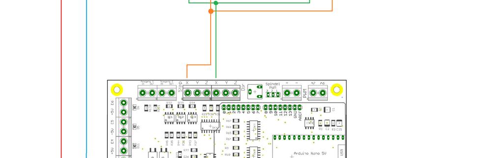
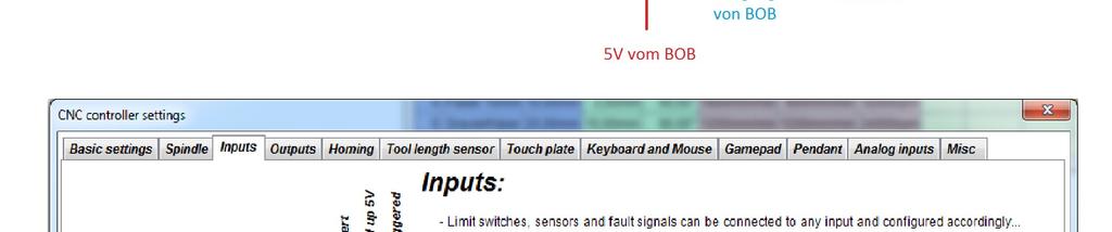
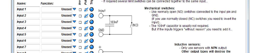
5 Inputs Each input port is provided with its pin number When the limit switch is pressed, it internally switches to ground and Estlcam detects a response at the input. PNP sensors switch with the switching voltage so they are also connected. 5 Stefan Gemeinert,Frühlingstrasse Erdweg

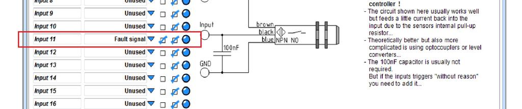
6 Connection a NPN-Sensors 6 Stefan Gemeinert,Frühlingstrasse Erdweg

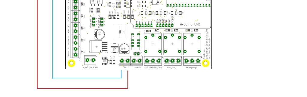
7 Outputs Spindle output can be used to switch on the spindle On the Board are 2 Relays up to 230V/10A (2,2KW bei 230V) Attention: do not connect switching power supplies because they have a very high inrush current, the relay contacts may be defective 7 Stefan Gemeinert,Frühlingstrasse Erdweg

8 Output 1 and 2 Jumper of Position 1-2 is direct Output Jumper of Position 2-3 is switched the Relays Output 1 and 2 8 Stefan Gemeinert,Frühlingstrasse Erdweg


9 Connection Driver The outputs for the Driver can be loaded with max. 50mA It is also possible to connect 2 driver output stages in parallel to one output for 2 step or servomotors, if the 50mA is not exceeded. ENA +, ENA- you must not connected. IMPORTANT: GND must always be connected everywhere, from the NT to the board and to the driver 9 Stefan Gemeinert,Frühlingstrasse Erdweg

10 1 0 Stefan Gemeinert,Frühlingstrasse Erdweg

11 Spindle PWM Output A frequency converter can be connected for the analogue signal. With jumper spindle PWM comes with bridge 1-2 = 5V or bridge 2-3 = 10V as output signal. The potentiometer R13 is set so that at 5V PWM output from the PC a 10V analog signal comes. You can adjust the 10V if you have to close jumper JP1 so that a 5V signal is generated and measured with the multimeter at the output 10V and if necessary read just the potentiometer. After that, remove jumper JP1 again. 1 1 Stefan Gemeinert,Frühlingstrasse Erdweg

12 ext. Emergency stop switch the external emergency stop is connected as an opener and switches off all signals on the breakout board after pressing. You must the Failure input in Estlcam activated. If jumper JP2 is closed, the emergency stop is ignored. Which is set in basic attitude so. 1 2 Stefan Gemeinert,Frühlingstrasse Erdweg

13 Arduino NANO If an Arduino Nano is used, you must solder the two female connectors with a commercially available soldering iron. If desired, I can solder that to you before shipping. Just let me know! 1 3 Stefan Gemeinert,Frühlingstrasse Erdweg
14 Output A6 and A7 1 4 Stefan Gemeinert,Frühlingstrasse Erdweg


15 Failure Settings for JMC Motors 1 5 Stefan Gemeinert,Frühlingstrasse Erdweg Tel:

16 1 6 Stefan Gemeinert,Frühlingstrasse Erdweg
Breakoutboard for ESS Smoothstepper
 Breakoutboard for ESS Smoothstepper Operation Manual All rights to these operating instructions remain with cnc-technics. Texts, information and illustrations of these operating instructions may not be
Breakoutboard für UC400ETH
 Breakoutboard für UC400ETH Operation Manual All rights to these operating instructions remain with cnc-technics. Texts, information and illustrations of these operating instructions may not be reproduced,
GUIDE TO SP STARTER SHIELD (V3.0)
") OVERVIEW: The SP Starter shield provides a complete learning platform for beginners and newbies. The board is equipped with loads of sensors and components like relays, user button, LED, IR Remote and
OVERVIEW: The SP Starter shield provides a complete learning platform for beginners and newbies. The board is equipped with loads of sensors and components like relays, user button, LED, IR Remote and
USER S MANUAL VER.2. C76- MULTIFUNCTION CNC BOARD Rev. 1.4
 USER S MANUAL VER.2 C76- MULTIFUNCTION CNC BOARD Rev. 1.4 MARCH 2018 User s Manual Page i USER'S MANUAL TABLE OF CONTENTS Contents Page # 1.0 FEATURES... 1 2.0 I/O SPECIFICATIONS... 2 3.0 BOARD DESCRIPTION...
USER S MANUAL. C32- DUAL PORT MULTIFUNCTION CNC BOARD Rev. 4
 USER S MANUAL C32- DUAL PORT MULTIFUNCTION CNC BOARD Rev. 4 August, 2012 USER'S MANUAL TABLE OF CONTENTS Page # 1.0 FEATURES... 1-1 2.0 SPECIFICATIONS... 2-3 3.0 BOARD DESCRIPTION... 3-4 4.0 FUNCTIONAL
Manual 5 Axis CNC Interface Breakout Board Model#-DB25-1R5AM
 Manual 5 Axis CNC Interface Breakout Board Read this manual carefully before making connections to the board. Store this manual away for further reference. Safety Notes: The electronics of the control
Hardware Manual CNC760
 Hardware Manual CNC760 Revision 3 6 December, 2017 Released Copyright 2017 by Eding CNC History: Revision Date Author 1 22-5-2017 AB 2 23-6-2017 AB 3 6-12-2017 AB Revision overview: Revision Remarks 1
PP-BOB2-V1.0 PARALLEL PORT BREAKOUT BOARD
 PP-BOB2-v1 PARALLEL PORT BREAKOUT BOARD Document: Operation Manual Document #: T17 Document Rev: 2.0 Product: PP-BOB2-v1.0 Product Rev: 1.0 Created: March, 2013 Updated: Dec, 2014 THIS MANUAL CONTAINS
PP-BOB2-V2.0 PARALLEL PORT BREAKOUT BOARD
 PP-BOB2-V2 PARALLEL PORT BREAKOUT BOARD Document: Operation Manual Document #: T18 Document Rev: 1.0 Product: PP-BOB2-V2.0 Product Rev: 1.0 Created: October, 2015 THIS MANUAL CONTAINS INFORMATION FOR INSTALLING
PLCM-B1 Breakout board for PLCM-E3/E3p controller
 www.purelogic.ru User manual CONTENTS: 1. General information... 2 2. Delivery set... 2 3. Technical specifications... 3 4. Key features... 4 5. Sockets purpose and indication... 6 6. Connection... 11
USER S MANUAL. C11S- MULTIFUNTCION CNC BOARD Rev. 1.2
 USER S MANUAL C11S- MULTIFUNTCION CNC BOARD Rev. 1.2 SEPTEMBER 2014 User s Manual Page i TABLE OF CONTENTS Page # 1. Overview... 1 2. Features... 1 3. Specifications... 3 4. BOARD DESCRIPTION... 4 5. Special
Operating instructions CNC Motion Controller: AC-CNC2017-2S (REV03)
") Operating instructions CNC Motion Controller: AC-CNC2017-2S (REV03) www.arduinoclub.de Dear customer, thank you for choosing our product. All our products are checked and subject to the controls of our
Operating instructions CNC Motion Controller: AC-CNC2017-2S (REV03) www.arduinoclub.de Dear customer, thank you for choosing our product. All our products are checked and subject to the controls of our
Manual. Model#-DB25M-3R6A. 6 Axis CNC Interface Breakout Board. Lastest update : Feb Store this manual away for further reference.
 Manual 6 Axis CNC Interface Breakout Board Model#-DB25M-3R6A Lastest update : Feb 2016 Read this manual carefully before making connections to the board. Store this manual away for further reference. Safety
ACORN User Guide For Revision (Aka Acorn_rev3) Updated 1/23/17
 Updated 1/23/17") ACORN User Guide For Revision 171025 (Aka Acorn_rev3) Updated 1/23/17 Overview ACORN is technically a breakout board for the BeagleBone Green or BeagleBone Black embedded computer. The remainder of this
ACORN User Guide For Revision 171025 (Aka Acorn_rev3) Updated 1/23/17 Overview ACORN is technically a breakout board for the BeagleBone Green or BeagleBone Black embedded computer. The remainder of this
USER S MANUAL VER.1. C11G- MULTIFUNTCION CNC BOARD Rev. 9
 USER S MANUAL VER.1 C11G- MULTIFUNTCION CNC BOARD Rev. 9 MARCH, 2017 User s Manual Page i USER'S MANUAL TABLE OF CONTENTS Contents Page # 1.0 OVERVIEW... 1 2.0 FEATURES... 1 3.0 SPECIFICATIONS... 2 4.0
USER S MANUAL. C35S- QUICK SETUP BREAKOUT BOARD Rev. 1.3
 USER S MANUAL C35S- QUICK SETUP BREAKOUT BOARD Rev. 1.3 FEBRUARY, 2015 USER'S MANUAL TABLE OF CONTENTS Page # Contents 1.0 OVERVIEW... 1 2.0 FEATURES... 1 3.0 SPECIFICATIONS.... 2 4.0 BOARD DESCRIPTION...
USER S MANUAL. M16 POKEYS MOTION MOTHERBOARD Rev. 1.1 JUNE 2016.
 USER S MANUAL M16 POKEYS MOTION MOTHERBOARD Rev. 1.1 JUNE 2016. USER'S MANUAL TABLE OF CONTENTS Page # Contents 1.0 OVERVIEW... 1 2.0 FEATURES... 1 3.0 BOARD DESCRIPTION... 2 4.0 SPECIFICATIONS... 2 4.1
C23- DUAL PORT MULTIFUNCTION CNC BOARD Rev. 3.1
 C23- DUAL PORT MULTIFUNCTION CNC BOARD Rev. 3.1 User manual Rev. 2 1. Overview This card has been designed to provide a flexible interface and functions to computer CNC projects, by using the parallel
Centroid ACORN CNC controller Specification and Use Guide Updated 8/3/17. Overview
 Centroid ACORN CNC controller Specification and Use Guide Updated 8//7 Overview ACORN is technically a CNC control breakout board for the BeagleBone Green or BeagleBone Black embedded computer the Beagle
USER S MANUAL. C11- MULTIFUNTCION CNC BOARD Rev. 9.9
 USER S MANUAL C11- MULTIFUNTCION CNC BOARD Rev. 9.9 FEBRUARY, 2015 User s Manual Page i TABLE OF CONTENTS Page # 1. Overview... 1 2. Features... 1 3. Specifications... 3 4. BOARD DESCRIPTION... 4 5. Special
HDBB Breakout board user s manual
 HDBB Breakout board user s manual The HDBB breakout board was designed to use with our Whale2(-T)*, Whale3, Mammut* and Dugong servo drives or with any other third party stepper or servo drives which using
Comprehensive support USB hot-swappable, USB connection at any time to monitor the state, Mach3 work
 USB motion control card installation manual The card features: Supports all versions of Mach3, including the latest version of Mach3 R3.042.040. Supports all versions of Windows, including the latest version
IO3-R2 BREAKOUT BOARD
 IO3-R2 BREAKOUT BOARD DESCRIPTION Breakout board IO3-R2 (Revision R2) has digital buffer for STEP/DIR/ENA command signals and as such it is particularly suitable for the connection up to 4 microstep drives
C10- PARALLEL PORT INTERFACE CARD Rev. 8
 C10- PARALLEL PORT INTERFACE CARD Rev. 8 User manual Rev. 1 1. Overview This card provides an easy way of interfacing your inputs and outputs from you parallel port. It provides terminals for the connections
Apollo I Breakout Board User s Manual
 MACHMOTION Apollo I Breakout Board User s Manual 1/14/2012 Everything you need to know to set up and use your Apollo I Breakout Board. MachMotion Version 1.0.1 2 P a g e M a c h M o t i o n Copyright 2012,
GRBL SHIELD FOR ARDUINO UNO USER MANUAL
 GRBL SHIELD FOR ARDUINO UNO USER MANUAL YRCNC 2017 Introduction Thanks for supporting us! Hope you will have many hours of fun using this shield and that plenty hours of issueless cutting! The main features
Pridgen Vermeer Robotics ATmega128 Revision 0
 Features: 6x 8-bit I/O Ports 4x A/D Inputs 6x PWM Headers 2x RS 232 Terminals Power Bus LCD Header (4-bit mode) Smart Power Connecter Power Switch Header Power LED Debug LED Note: Some pins have multiple
USER S MANUAL. C33 - MULTIFUNCTION ROUTER BOARD BOARD Rev. 4
 USER S MANUAL C33 - MULTIFUNCTION ROUTER BOARD BOARD Rev. 4 June 2013 USER'S MANUAL TABLE OF CONTENTS Page # Contents 1.0 OVERVIEW... 3 2.0 FEATURES... 3 3.0 SPECIFICATIONS... 4 4.0 FUNCTIONAL BLOCK DIAGRAMS...
uservo box instruction manual
 Safety notes uservo box instruction manual Every machine controlled by computer (PC) can be really dangerous for human life and health. Comply with bolow rules and use Your common sense while working with
C11G- MULTIFUNTCION CNC BOARD Rev. 8.2
 C11G- MULTIFUNTCION CNC BOARD Rev. 8.2 User manual Rev. 2 1. Overview This card has been designed to provide a flexible interface and functions to your computer projects, by using the parallel port control
C33- MULTIFUNCTION ROUTER BOARD Rev. 2
 C33- MULTIFUNCTION ROUTER BOARD Rev. 2 User manual Rev. 1 1. Overview This card provides an easy way of interfacing your router based spindle with your steeper motor driver board. This board includes a
SHIELD-MD10 Cytron 10A Motor Driver Shield
 SHIELD-MD10 Cytron 10A Motor Driver Shield User's Manual V1.0 October 2012 Created by Cytron Technologies Sdn. Bhd. All Right Reserved 1 Index 1. Introduction 3 2. Packing List 4 3. Product Specification
PLCIO2 Programmable Logic Controller Updated 3/26/10
 Overview: PLCIO2 Programmable Logic Controller Updated 3/26/10 PLCIO2 is a programmable logic controller which provides: 35 Inputs (bipolar, with a choice of 5 or 24) 39 Outputs (20SPST, 2 SPDT, 17 open
Explorer V1.20. Features
 V1.20 Multi-function USB I/O Expander and Controller Features Dual h-bridge 1.3A motor drive with PWM speed control 4.6V to 10.8V input range USB communication 4x digital inputs 2x analogue inputs 7x 100mA
C10S- PARALLEL PORT INTERFACE CARD Rev. 1.4
 USER S MANUAL VER.1 C10S- PARALLEL PORT INTERFACE CARD Rev. 1.4 SEPTEMBER, 2016 User s Manual Ver.1 Page i USER'S MANUAL TABLE OF CONTENTS Page # 1. OVERVIEW... 1 2. FEATURES... 1 3. SPECIFICATIONS...
USER S MANUAL VER.1. C10D- PARALLEL PORT INTERFACE CARD BOARD Rev. 1
 USER S MANUAL VER.1 C10D- PARALLEL PORT INTERFACE CARD BOARD Rev. 1 MARCH 2018 User s Manual Page i USER'S MANUAL TABLE OF CONTENTS Contents Page # 1.0 OVERVIEW... iii 2.0 FEATURES... iii 3.0 SPECIFICATIONS...
DEV16T. LCD Daughter board
 LCD Daughter board Table of Contents 1 Introduction...2 2 Features...3 3 Expansion Connectors...4 3.1 Daughter Board Connectors...4 4 LCD Display...5 5 Input Buttons S1 to S4...5 6 Buzzer...5 7 Connector
EN006 - DigiSpeed Selection Chart
 - Selection Chart The range is designed to allow you to control the speed of your spindle motor from your CNC software. They do this by accepting a control signal from the CNC software and converting to
UNIPORT V2. Uniport V2
 UNIPORT V2 Uniport V2 USB powered Parallel port interconnection board with optical isolated inputs, buffered outputs, charge pump interlock and power relays Specification Full optical isolation of all
C35- QUICK SETUP BREAKOUT BOARD Rev. 1.1
 C35- QUICK SETUP BREAKOUT BOARD Rev. 1.1 User manual Rev. 1 1. Overview This card provides an easy way of interfacing your inputs and outputs from the parallel port. It provides terminals and RJ45 for
DigiSpeed-SD DC-06. Isolated Control Voltage Generator User s Guide. DigiSpeed-SD PCB Ver:3.0 Mach3 Ver: 2.+ DigiSpeed-SD - Users Guide Page 1
 DigiSpeed-SD - Users Guide Page 1 Updated: 4 th May 2011 DigiSpeed-SD DC-06 Isolated Control Voltage Generator User s Guide DigiSpeed-SD PCB Ver:3.0 Mach3 Ver: 2.+ DigiSpeed-SD - Users Guide Page 2 Homann
HUB-ee BMD-S Arduino Proto Shield V1.1
 HUB-ee BMD-S Arduino Proto Shield V1.1 User guide and assembly instructions Document Version 0.5 Introduction & Board Guide 2 Schematic 3 Quick User Guide 4 Assembly Guide 6 Kit Contents 7 1) Diodes and
TurboTaig Instruction Manual
 TurboTaig Instruction Manual Version: 2.2 Peter Homann 20 View St Highett 3190 homann@smartchat.net.au http://people.smartchat.net.au/~homann 1 Table of Contents Table of Contents... 2 Introduction...
USER S MANUAL C10- PARALLEL PORT INTERFACE CARD
 USER S MANUAL C10- PARALLEL PORT INTERFACE CARD Rev. 10 June, 2012 USER'S MANUAL TABLE OF CONTENTS Page # 1. OVERVIEW... 1 2. FEATURES... 1 3. SPECIFICATIONS... 2 4. BOARD DESCRIPTION... 3 Using configuration
UIM2901-5A. Page 2. UI Robot Technology Co. LTD M EN. Please pay attention to the following before using the UIROBOT products:
 User Manual MACH3 Breakout Board Please pay attention to the following before using the UIROBOT products: UIROBOT products meet the specification contained in their particular Data Sheet. UIROBOT will
UNIPORT V3. C R H Electronics Design
 UNIPORT V3 V C R H Electronics Design Uniport V3 USB powered Parallel port interconnection board with optical isolated inputs, buffered outputs, charge pump interlock and power relays By C R Harding Specification
Digital DRIVE for Brushless motor MD Serial
 Digital DRIVE for Brushless motor MD Serial Installation guide Read manual before installing and respect all indications with this icon: MD-GI/EN Table of Contents 1- Introduction... 3 1-1- Warning...
MP6500 Stepper Motor Driver, Digital Current Control
 This breakout board for the MPS MP6500 micro stepping bipolar stepper motor driver is Pololu s latest stepper motor driver. The module has a pinout and interface that are very similar to that of our popular
Motorino. Ausgabe Copyright by Joy-IT 1
 3 3 Motorino Ausgabe 01.02.2017 Copyright by Joy-IT 1 3 Motorino Index 1. Introduction 2. Technical specification & security information 3. Setting up the Arduino 4. Installation 5. Setting up the I2C-Address
Thursday, September 15, electronic components
 electronic components a desktop computer relatively complex inside: screen (CRT) disk drive backup battery power supply connectors for: keyboard printer n more! Thursday, September 15, 2011 integrated
USER S MANUAL. CNC Servo Stepper Motor Control Box CH4EV12-1 Rev. 1
 USER S MANUAL CNC Servo Stepper Motor Control Box CH4EV12-1 Rev. 1 January, 2013 i USER'S MANUAL TABLE OF CONTENTS Page # Contents 1.0 FEATURES... 1 2.0 SPECIFICATIONS... 2 3.0 SYSTEM REQUIREMENTS... 2
User Manual of 5Axis Breakout Board
 WWW.VALLDER.COM User Manual of 5Axis Breakout Board Safety Statement Vallder Ltd is not liable or responsible for any accidents, injuries, equipment damage, property damage, loss of money or loss of time
UB1. Owner s manual. Doc E1.5Rev0 (8/23/2017) for PCB ver Page 1
 for PCB ver Page 1") UB1 Owner s manual Doc E1.5Rev0 (8/23/2017) for PCB ver 1.5 www.cncroom.com Page 1 Introduction It is perhaps well understood that in an industrial environment, personal computers, motion control boards
UB1 Owner s manual Doc E1.5Rev0 (8/23/2017) for PCB ver 1.5 www.cncroom.com Page 1 Introduction It is perhaps well understood that in an industrial environment, personal computers, motion control boards
Rover 5. Explorer kit
 Rover 5 Explorer kit The explorer kit provides the perfect interface between your Rover 5 chassis and your micro-controller with all the hardware you need so you can start programming right away. PCB Features:
UCBB dual port breakout board user's manual
 UCBB dual port breakout board user's manual 1/14 Contents 1 Features 2 Dimensions 3 Connectors 3.1 Screw terminals 3.2 IDC ports 3.3 Powering 3.4 Outputs 3.5 Inputs 4 LED indicators 5 Example connections
Replicape Rev B 3D printer controller board
 Replicape Rev B 3D printer controller board SKU 102991007 Description Replicape is a high end 3D printer electronics package in the form of a Cape that can be placed on a BeagleBone Black. This page is
PMDX-108-Output. 8-Channel Isolated Output Board for PC parallel port pins 2-9. User s Manual
 PMDX-108-Output 8-Channel Isolated Output Board for PC parallel port pins 2-9 User s Manual Date: 25 February 2010 PMDX Web: http://www.pmdx.com 9704-D Gunston Cove Rd Phone: +1 (703) 372-2975 Lorton,
Sanguino TSB. Introduction: Features:
 Sanguino TSB Introduction: Atmega644 is being used as CNC machine driver for a while. In 2012, Kristian Sloth Lauszus from Denmark developed a hardware add-on of Atmega644 for the popular Arduino IDE and
3-Axis Stepper Drive Datasheet MX3660
 3-Axis Stepper Drive Datasheet MX3660 3-Axis Stepper Drive + Breakout Board, 20-60VDC, 6A Peak Version 0.0.2 http://www.leadshine.com Features Three individual stepper drive boards Suitable for NEMA17
USER S MANUAL. CNC Stepper Motor Control Box CS3EA4-1 Rev. 1
 USER S MANUAL CNC Stepper Motor Control Box CS3EA4-1 Rev. 1 April, 2012 USER'S MANUAL TABLE OF CONTENTS Page # Contents 1.0 FEATURES... 2 2.0 SPECIFICATIONS... 3 3.0 SYSTEM REQUIREMENTS... 3 4.0 WARNING...
Logosol Supervisor I/O Controller CNC-SK-2310g2
 Features LS- compatible Safety Bus interface Safety Interlock functions 00% relay contact based Dual mechanical Relay based Power Supply control interface with safety line Spindle control interface with
RoboClaw 120A/160A/200A Dual Channel Motor Controller
 RoboClaw 2x160A, 34VDC Dual Channel RoboClaw 2x120AHV, 60VDC Dual Channel RoboClaw 2x160AHV, 60VDC Dual Channel RoboClaw 2x200AHV, 60VDC Dual Channel Brushed DC Motor Controllers Version 2.1 (c) 2016 Ion
CPU5A Economy Series USBCNC software included. Features
 CPU5A Economy Series 125 KHz step frequency, 4 axes. Card size 100x100mm. USB 2.0 connection. 100 Mbit Ethernet connection (*). 5 Status LED's. Full 4 axes interpolation (*). 7 Standard CNC outputs. 0-10V
A4988 Stepper Motor Driver Carrier with Voltage Regulators
 1 of 6 12/2/2011 6:37 PM A4988 Stepper Motor Driver Carrier with Voltage Regulators Pololu item #: 1183 26 in stock Price break Unit price (US$) 1 19.95 10 17.95 100 13.97 Quantity: backorders allowed
C50- PARALLEL PORT INTERFACE CARD Rev. 1
 C50- PARALLEL PORT INTERFACE CARD Rev. 1 User manual 1. Overview This card provides an easy way of interfacing your inputs and outputs from you parallel port. It provides terminals for the connections
ACE-SDC-V3 Stepper Driver +Controller with USB 2.0 Communication
 ACE-SDC-V3 Stepper Driver +Controller with USB 2.0 Communication ACE-SDC-V3 Manual page 1 rev 1.00 COPYRIGHT 2008 ARCUS, ALL RIGHTS RESERVED First edition, April 2008 ARCUS TECHNOLOGY copyrights this document.
The Sentinel - Talon-SRX Breakout Board, rev A User s Guide
 The Sentinel - Talon-SRX Breakout Board, rev A User s Guide December 13, 2016 - document rev A Thank you for purchasing the the Sentinel Talon-SRX Breakout Board. Within this guide, you will find information
AXBB-E ethernet motion controller and breakout board user's guide
 AXBB-E ethernet motion controller and breakout board user's guide Version of this document: 1.0002 1/29 Contents 1.Description of the AXBB-E device. 2.Safety notes. 3.Physical installation of the device.
Physical Computing Self-Quiz
 Physical Computing Self-Quiz The following are questions you should be able to answer by the middle of the semeter in Introduction to Physical Computing. Give yourself 6.5 points for questions where you
InStep Plus Hardware Manual (Instep with Expansion Board) For Main board Rev 1 and Expansion board Rev 0
 For Main board Rev 1 and Expansion board Rev 0") Design, Application and Service of Electronics in Industry InStep Plus Hardware Manual (Instep with Expansion Board) For Main board Rev 1 and Expansion board Rev 0 (To be used in conjunction with the appropriate
Design, Application and Service of Electronics in Industry InStep Plus Hardware Manual (Instep with Expansion Board) For Main board Rev 1 and Expansion board Rev 0 (To be used in conjunction with the appropriate
USER S MANUAL. C68 KFLOP MOTHERBOARD Rev. 3 JANUARY 2015.
 USER S MANUAL C68 KFLOP MOTHERBOARD Rev. 3 JANUARY 2015. USER'S MANUAL TABLE OF CONTENTS Page # Contents 1.0 OVERVIEW... 1 2.0 FEATURES... 1 3.0 BOARD DESCRIPTION... 2 4.0 SELECT JUMPER DEPENDING OF THE
Objectives: Learn how to input and output analogue values Be able to see what the Arduino is thinking by sending numbers to the screen
 Objectives: Learn how to input and output analogue values Be able to see what the Arduino is thinking by sending numbers to the screen By the end of this session: You will know how to write a program to
3 axes stepper motor driver board. Slider SFX. Upgrading milling and turning machines to CNC machines by use of stepper motors. User guide SFX Page 1
 3 axes stepper motor driver board Slider SFX Upgrading milling and turning machines to CNC machines by use of stepper motors User guide SFX Page 1 Copyright Thorsten Ostermann, 2008 The present stepper
4.8 Expansion Module MAC00-FS1/FS4
 .8 Expansion Module MAC00-FS/FS MAC00-FS With M connectors MAC00-FS With D sub connectors TT08GB.8. High speed serial RS8 module MAC00-FS and FS Introduction The MAC00-FS and FS are used for high speed
G540 User Manual. Date Modified: March 5, 2012 Page 1 of 10
 G540 User Manual Date Modified: March 5, 2012 Page 1 of 10 DIMENSIONS PHYSICAL AND ELECTRICAL RATINGS Minimum Maximum Units Supply Voltage 18 50 VDC Motor Current 0 3.5 A Power Dissipation 1 13 W Short
RoboClaw 2x30A Dual Channel Motor Controller
 RoboClaw 2x30A, 34VDC Dual Channel Brushed DC Motor Controller Version 2.2 (c) 2016 Ion Motion Control. All Rights Reserved. Feature Overview: 60 Amps Peak Per Channel Channel Bridging Supported Dual Quadrature
TECO L510 Inverter. Quick Start Guide. Step 1. Supply & Motor connection
 Quick Start Guide TECO L510 Inverter This guide is to assist you in installing and running the inverter and verify that it is functioning correctly for it s main and basic features. For detailed information
Series P49 - Housing M18 M30 Q50. PIL Sensoren GmbH March 2013 V1.0
 - Housing M18 M30 Q50 4 Cost effectiv series for basic applications with high quantities cylindrical housing M18 M30 / cubical housing 80x80 mm for various installation and application requirements large
EDUCATION EXPERIENCES WITH A USB INTERFACE
 Practice and Theory in Systems of Education, Volume 4 Number 1 2009 EDUCATION EXPERIENCES WITH A USB INTERFACE József NEMES (University of West-Hungary, Szombathely, Hungary) njozsef@ttmk.nyme.hu On the
USER S MANUAL VER.1. C10- PARALLEL PORT INTERFACE CARD BOARD Rev. 11
 USER S MANUAL VER.1 C10- PARALLEL PORT INTERFACE CARD BOARD Rev. 11 FEBRUARY, 2017 User s Manual Page i USER'S MANUAL TABLE OF CONTENTS Contents Page # 1.0 OVERVIEW... iii 2.0 FEATURES... iii 3.0 SPECIFICATIONS...
Version 1.7. Module Firmware Version 4
 Version 1.7 Module Firmware Version 4 January 2018 Publication EZQ-1000 Module firmware and functionality is protected by U.S. and international patents. For complete patent information visit www.pulseroller.com/patents
3. The circuit is composed of 1 set of Relay circuit.
 Part Number : Product Name : FK-FA1420 ONE CHANNEL 12V RELAY MODULE This is the experimental module for a relay controller as the fundamental controlling programming. It is adaptable or is able to upgrade
MAKEVMA409 L298N DUAL BRIDGE DC STEPPER CONTROLLER BOARD USER MANUAL
 L298N DUAL BRIDGE DC STEPPER CONTROLLER BOARD USER MANUAL USER MANUAL 1. Introduction To all residents of the European Union Important environmental information about this product This symbol on the device
BLD04A Brushless DC Motor Driver
 BLD04A Brushless DC Motor Driver User s Manual V1.1 MAY 2011 Information contained in this publication regarding device applications and the like is intended through suggestion only and may be superseded
CNC4PC. MULTIFUNCTION CNC BOARD Rev2
 CNC4PC Manual MULTIFUNCTION CNC BOARD Rev2 Overview This card has been designed to provide a flexible interface and functions to your computer projects, by using the parallel port control software. This
G540 MANUAL MULTIAXIS STEP MOTOR DRIVE
 G540 MANUAL MULTIAXIS STEP MOTOR DRIVE PRODUCT DIMENSIONS PHYSICAL AND ELECTRICAL RATINGS Minimum Maximum Units Supply Voltage 18 50 VDC Motor Current 0 3.5 A Power Dissipation 1 13 W Short Circuit Trip
Apollo III INSTALLATION MANUAL
 Apollo III INSTALLATION MANUAL 2 P a g e 5/1/14 N0112 This manual covers the setup and configuration of the Apollo III motion controller connected to the control using Mach3. Formatting Overview: Menus,
Connection instructions for HF-Spindle Mechatron HFSAC (0,8KW)
") Connection instructions for HF-Spindle For the High-Z series with Zero3 controller Software: WinPC-NC Pro with 2 LPT-interfaces or WinPC-NC USB www.cnc-step.de Status: 08.12.2015 Summary This document
Connection instructions for HF-Spindle For the High-Z series with Zero3 controller Software: WinPC-NC Pro with 2 LPT-interfaces or WinPC-NC USB www.cnc-step.de Status: 08.12.2015 Summary This document
Controlling a fischertechnik Conveyor Belt with Arduino board
 EXPERIMENT TITLE: Controlling a fischertechnik Conveyor Belt with Arduino board PRODUCTS USED: CHALLENGE: AUTHOR: CREDITS: Interface and control a conveyor belt model (24 Volts, fischertechnik) with an
MODEL DRIVER Ic Ip VDC
 Provides Mounting & Connections for Stepnet Module CANopen Stepping Driver FEATURES Develop & Debug Stepnet projects then transfer design to OEM pc board. MODEL DRIVER Ic Ip VDC -075-01 STM-075-07 5 7
C45 - LIMIT AND HOME UNIVERSAL BOARD Rev. 1
 C45 - LIMIT AND HOME UNIVERSAL BOARD Rev. 1 User manual Rev. 1 1. Overview This card provides an easy means of connecting optical, mechanical and proximity sensor to operate as homing and limit switches
Digital Servo Drive. For Brushless Motor or Brushed Motor MDSC4805 / MDSC4810 / MDSC4830 / MDSC4850. Datasheet V1.1. Jun 2, 2017
 Digital Servo Drive For Brushless Motor or Brushed Motor MDSC4805 / MDSC4810 / MDSC4830 / MDSC4850 Datasheet V1.1 Jun 2, 2017 Copyright @ Mach Motion Products, INC. 2017 All rights reserved. No part of
DigiSpeed-XL DC-02. Isolated Control Voltage Generator User s Guide. DigiSpeed-XL PCB Ver:6.0 Firmware Ver: 6.x Mach3 Ver: 1.84
 DigiSpeed-XL - Users Guide Page 1 Updated: 14. September 2007 DigiSpeed-XL DC-02 Isolated Control Voltage Generator User s Guide DigiSpeed-XL PCB Ver:6.0 Firmware Ver: 6.x Mach3 Ver: 1.84 DigiSpeed-XL
Robotic Kits. AVR SWARM Robot Kits
 Robotic Kits The Nexus Swarm Robot Kit is the official robot for the Nexus competitions. It is a complete, high-performance mobile platform featuring two gearmotors, five reflectance sensors, two IR Cube
ULN2065B SWITCH BOARD
 1 ULN2065B SWITCH BOARD FEATURES 2 x ULN2065B(80V 1.5A Quad Darlington switches) Indication LEDs for the output status and input channels Screw Terminal Blocks for Relay outputs and opto input channels
SPIRIT. Phase 5 Analog Board Computer and Electronics Engineering
 SPIRIT Phase 5 Analog Board Computer and Electronics Engineering In this exercise you will assemble the analog controller board and interface it to your TekBot. Print out the schematic, silkscreen and
TB6600 Stepper Motor Driver
 TB6600 Stepper Motor Driver V1.0 07 2018 Open Source Mechatronics LTD 2018 Safety Statement The author of this document is not liable or responsible for any accidents, injuries, equipment damage, property
Unipower HPL600. Unipower HPL600
 Unipower HPL600 Tool Monitor System TMS...2 1. Introduction...2 2. Installation...2 2.1 Typical installation... 2 2.2 Supply voltage... 2 2.3 Analogue input... 2 2.4 Digital inputs K1,K2.... 2 2.5 Connecting
USER S MANUAL VER.3. C25- SMOOTH STEPPER LPT BOARD Rev. 5
 USER S MANUAL VER.3 C25- SMOOTH STEPPER LPT BOARD Rev. 5 MAY, 2017 User s Manual Page i USER'S MANUAL TABLE OF CONTENTS Contents Page # 1.0 FEATURES... 1 2.0 SPECIFICATIONS... 1 3.0 FUNCTIONAL BLOCK DIAGRAMS...
P/N: P E201. imotioncube BX-CAN DATASHEET. Page: 1 of 5. Motor sensor configurations. Sensor. All dimensions are in mm.
 imotioncube BX-C DATASHEET Sensor Incr. Encoder Motor sensor configurations Motor PMSM BLDC DC ST BRUSH (2-ph) ST (3-ph) Incr. Encoder + Hall Analog Sin/Cos encoder SSI BiSS-C* Linear Halls Tacho Open-loop