DLCP. Digital Loudspeaker Cross-over Platform Datasheet
|
|
|
- Benedict Ross
- 5 years ago
- Views:
Transcription

1 Kattegat JP Groningen, The Netherlands sales@hypex.nl Digital Loudspeaker Cross-over Platform Datasheet Highlights Fully user customized filtering Great audio performance Field updatable firmware Current-mode serial I/F USB audio Compact: 110mm x110mm x30mm Low weight: 140gr. Description The is a complete hardware/firmware platform for digitally filtered (6 channels) and corrected active multiway loudspeakers. Digital response correction allows significant extra degrees of freedom in the acoustic design of a loudspeaker. Driver parameters can be selected for best efficiency and distortion instead of electrical damping, and the cabinet can now be fully optimized for radiation pattern. For further information, please read the manual (in progress). Features Compact design Personal Computer controlled Input sample rates up to 192kHz Analogue and digital inputs Digital balanced audio loop-through Low-jitter discrete clock oscillator Balanced audio in and out Six channel active filtering Fully user-configurable filters Firmware updateable by USB Separate Clock and Data Paths Six user configurable analogue balanced outputs High-Level outputs permit direct interface with NC400 / buffered UcD ST and HG power amplifiers Analogue input gain trim 9 local regulators IIR filtering 96kHz processor sampling rate Stand-by mode On board Molex Microfit output connectors Connector for external LED. Optional control board with IR receiver for IR remote control, LCD display and buttons Link communication (only with two or more modules and in combination with a controller) Applications High-end consumer audio Digital pre amplifier Active speakers up to six-way Three-way stereo active system PA systems Studio monitors
2 Contents 1 Block diagram Performance data Recommended Operating Conditions Connections Pin characteristics Typical Performance Graphs Dimensions Revision History R1 2

3 1 Block diagram R1 3
4 2 Performance data MBW=20kHz (20Hz-20Khz), unweighted, all filters set to unity, gain adjust 0dB unless otherwise noted Item Symbol Min Typ Max Unit Notes Input level 1) Gain adjust 0dB VIN Gain adjust +6dB dbu 12 Gain adjust +12dB 9 Gain adjust +15dB Output level V OUT 2.59 V 0 dbfs Signal/Noise ratio SNR 113 db Digital in 110 db Analogue in Total harmonic distortion + noise -102 db Digital in, -1dBFS THD+N -102 db Analogue in, -1dBFS Output noise digital U N 5,8 Output noise analogue 7,4 uv 20Hz-20kHz DM Input Impedance Z IN, DM 44 kω Differential mode CM Input Impedance Z IN, CM 2.2 MΩ Common mode Output Impedance Z OUT 100 Ω Frequency Response 0 35 khz +/- 0.1dB (relative to 1kHz) db DC-0.45fs or 42kHz (whichever is lowest) DSP sampling rate Fs khz ADC sampling rate Fs khz Supported digital sampling rates Fs 32, 44.1, 48, 88.2, 96, 192 khz All input rates converted to 93.75kHz Delay per channel ms Set in software CM Rejection Ratio CMRR 70 db All frequencies (gain adjust +15) Channel separation >108 db Left/Right and interchannel seperation Analogue latency 750 us Digital latency 1.85 ms 96kHz input sample rate Standby Current I STBY 30 ma Note 1:See J5/J8 in Connections. 3 Recommended Operating Conditions Item Symbol Min Typ Max Unit Notes Supply voltage ) ) Vdc Positive and negative supply voltage Note 1:Unit shuts down when the positive rail drops below 15V. Note 2: Especially on high supply voltages; make sure there s enough airflow to cool the regulators. R1 4
5 4 Connections R1 5
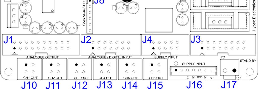
6 Overview of the connectors on the Name Function J1 Analogue audio output header (contains all audio outputs from J10-J15) J2 Analogue/Digital audio in and digital output header J3 I/O connector (USB, Relay, Control) J4 Power supply connector (Do not use when a Hypex SMPS module is connected with J16) J5 Gain adjust header analogue left input J8 Gain adjust header analogue right input J17 Standby supply connector J10 Analogue audio output ch1 J11 Analogue audio output ch2 J12 Analogue audio output ch3 J13 Analogue audio output ch4 J14 Analogue audio output ch5 J15 Analogue audio output ch6 J16 Power Supply connector Hypex SMPS (Do not use when J4 is connected to another supply) J7 LED connector J6 Microcontroller & DSP programmer connector, not used by user JP5 Jumpers for programming or normal operation, not used by user 4.1 J1: Analogue audio out Connector type: 2.54mm pitch dual row 10 pin box header Pin Type Function 1 Output Ch1 positive out 2 Output Ch1 negative out 3 Output Ch2 positive out 4 Output Ch2 negative out 5 - GND 6 - GND 7 Output Ch3 positive out 8 Output Ch3 negative out 9 Output Ch4 positive out 10 Output Ch4 negative out 11 - GND 12 - GND 13 Output Ch5 positive out 14 Output Ch5 negative out 15 Output Ch6 positive out 16 Output Ch6 positive out 17 Output Amp_enable 18 - GND 19 N.C. 20 N.C. R1 6

7 4.2 J2: Analogue/digital audio I/O Connector type: 2.54mm pitch dual row 7 pin box header Pin Type Function 1 Input Analogue left positive in 2 Input Analogue left negative in 3 Input Analogue right positive in 4 Input Analogue right negative in 5 - GND 6 - GND 7 Input S/PDIF in 8 Output S/PDIF out 9 Input AES positive in 10 Input AES negative in 11 Output AES positive out 12 Output AES negative out 13 Input Optical in 14 - GND Please place this filter on your analogue inputs if you don t use the optional input board; 4.3 J3: I/O USB,midi,relay Connector type: 2.54mm pitch dual row 8 pin box header Pin Type Function 1 Input Midi in positive 2 Input Midi in negative 3 Output Midi positive out 4 Output Midi negative out 5 In/output USB data positive 6 In/output USB data negative 7 Input USB VCC 8 - GND 9 Output Relay supply voltage 10 Output Relay 1 control 11 Output Relay 2 control 12 Output Relay 3 control 13 - GND 14 Output Controller board supply voltage (+5V) 15 For future use 16 N.C. R1 7
8 4.4 J7: External LED Connector type: 2.54mm pitch 2 pin header Pin Type Function 1 Output Led output (anode) 2 - GND (cathode) 4.5 J10-J15: Analogue audio out (ch1-ch6) Connector type: 2x2 pin Molex Microfit header type (see mates with cable part. Pin Type Function 1 Output Ch positive out 2 Output Ch negative out 3 Output Amplifier enable 4 - GND The audio output is differential. This means that ground is not part of the audio signal. When connecting an unbalanced amplifier, treat pins 1 and 2 as a floating output with pin 2 being the audio ground of the amplifier. Pin 4 may be used to attach the shield of a shielded twisted pair cable, but the audio ground connection of an unbalanced amplifier should never connect here. 4.6 J16: Hypex SMPS power supply Connector type JST ( JST-B7B-EHA, mates with JST-EHR-7 cable part. This connector should not be used when J4 is connected to another power supply. Pin Type Function 1 Output Supply standby (Electrically connected to pin 1 of J4) 2 Output Amplifier standby (Electrically connected to pin 2 of J4) 3 Input Positive input voltage (Electrically connected to pin 3 and 4 of J4) 4 N.C. 5 - GND 6 N.C. 7 Input Negative input voltage (Electrically connected to pin 7 and 8 of J4) 4.7 J4: Power Supply Connector type: 2.54mm pitch dual row 5 pin box header This connector should not be used when J16 is connected to a Hypex SMPS power supply. Pin Type Function 1 Output Supply standby (Electrically connected to pin 1 of J16) 2 Input Amplifier standby (Electrically connected to pin 2 of J16) 3 Input Positive input voltage (Electrically connected to pin 3 of J16) 4 Input Positive input voltage (Electrically connected to pin 3 of J16) 5 - GND 6 Input Standby voltage (Electrically connected to pin 1 of J17) 7 Input Negative input voltage (Electrically connected to pin 7 of J16) 8 Input Negative input voltage (Electrically connected to pin 7 of J16) 9 Input Amplifier positive supply voltage measurement 10 Input Amplifier negative supply voltage measurement 4.8 J17: Standby Connector type JST ( JST- B2P-VH, mates with JST-VHR-2N cable part. Pin Type Function 1 Input Standby voltage (Electrically connected to pin 6 of J4) 2 - GND R1 8
9 5 Pin characteristics 5.1 Amp_enable output This pin is controlled by the microcontroller (open collector). This pin is left floating, when the amplifier should be in standby modus/should be muted, in normal operation it s connected to ground. 5.2 Relay 1,2,3 control output These pins control the relays on the optional Inputboard. These are open collector outputs. Analogue Input select Relay control outputs High/Low Analogue 1 1 High (Open collector) 2 High (Open collector) 3 High (Open collector) Analogue 2 1 Low (Pulled to ground) 2 High (Open collector) 3 High (Open collector) Analogue 3 1 High (Open collector) 2 High (Open collector) 3 Low (Pulled to ground) Analogue 4 1 High (Open collector) 2 Low (Pulled to ground) 3 Low (Pulled to ground) 5.3 Amplifier standby This open collector output pin is controlled by the microcontroller, and is by default pulled up to the standby supply voltage. It s pulled to ground when the amplifiers should be enabled. For more information see datasheet of the Hypex SMPS XXX. 5.4 Supply standby output This pin is controlled by the microcontroller, and is high when the is in standby modus. When connected to a Hypex SMPS XXX, see datasheet of the connected SMPS for more information. In order to use this function a standby supply voltage must be present. 5.5 Amplifier positive supply voltage measurement input This pin can be used to measure the positive amplifier supply voltage, for a limiter, but is not yet implemented in software. Item Type Min Typ Max Unit Notes Positive Voltage on J4:9 Input TBD TBD TBD Vdc 5.6 Amplifier negative supply voltage measurement input This pin can be used to measure the negative amplifier supply voltage, for a limiter, but is not yet implemented in software. Item Type Min Typ Max Unit Notes Negative Voltage on J4:10 Input TBD TBD TBD Vdc 5.7 Relay supply voltage output Supply voltage for relays on optional Input PCB. Item Type Min Typ Max Unit Notes Voltage on J3:9 Output 5 Vdc Max. current= 110 ma. R1 9
10 5.8 External LED output A LED connected to J7 will light up when the is turned on, and flashes a few times when the supply voltage drops below 15Vdc. 5.9 Controller board supply voltage output This supply pin is used for the control board. Item Type Min Typ Max Unit Notes Voltage on J3:14 Output 5 Vdc 5.10 Positive input voltage Item Type Min Typ Max Unit Notes DC voltage on J4:3 and 4 Input Vdc /J16:3 Current 1) Input ma Current 1) Input ma With optional Inputboard and Control. Note 1: Maximum current value is drawn at min. input supply voltage, min. current value is drawn at max. input supply voltage (because of the DC-DC converters) Negative input voltage Item Type Min Typ Max Unit Notes DC voltage on J4:7 and 8 Input Vdc /J16:7 Current Input ma 5.12 Standby Input When you want to use the standby modus of the, you have to apply an external DC voltage (standby supply) on J17 / J4:6. Item Type Min Typ Max Unit Notes DC voltage on J17:1/J4:6 input Vdc Current Input ma 5.13 Chassis grounding All four mounting holes are connected to ground with a 100nF capacitor. Connect them all to chassis with a metal spacer for optimum EMI performance. R1 10
11 6 Typical Performance Graphs 6.1 Frequency response (Analogue) k 2k 5k 10k 20k 50k Hz 6.2 THD+N vs. input voltage (Analogue, 1Khz) d B r A dbr R1 11
12 6.3 THD+N vs. Frequency (Analogue in, -1 dbfs) d B r A k 2k 5k 10k 20k Hz 6.4 FFT (Analogue in, -20dBFS, 5kHz ) d B r A k 2k 3k 4k 5k 6k 7k 8k 9k 10k 11k 12k 13k 14k 15k 16k 17k 18k 19k 20k 21k 22k 23k 24k 25k Hz R1 12
13 7 Dimensions Top view Side view R1 13
14 DISCLAIMER: This product is designed for use in sound reproduction equipment in conjunction with Hypex amplifier modules. No representations are made as to fitness for use in other applications. Except where noted otherwise any specifications given pertain to this subassembly only. Responsibility for verifying the performance, safety, reliability and compliance with legal standards of end products using this subassembly falls to the manufacturer of said end product. LIFE SUPPORT POLICY: Use of Hypex products in life support equipment or equipment whose failure can reasonably be expected to result in injury or death is not permitted except by explicit written consent from Hypex Electronics BV. Warranty The work carries warranty out for all provable material and production defects for the duration of 24 months starting from sales. All damage, which is caused by wrong or inappropriate operation, is excluded from the warranty. 8 Revision History The following table shows the revision history for this document. Document Revision PCB Version Description Date R1 V1 Initial Draft R2 V3 Updated because of new hardware version R1 14
DCN23 Digital Crossover with 2 inputs and 3 outputs
 DCN23 Digital Crossover with 2 inputs and 3 outputs Features High performance Burr-Brown converters 24bit resolution 96kHz sampling frequency XOverWizard software Optical isolated USB interface 48 biquads
MINI DSP EVM KIT Application Manual
 MINI DSP EVM KIT Application Manual Table of contents 1. System overview... 3 2. Features... 3 3. MINI DSP module connections and controls... 4 3.1. External device connections... 5 3.1.1. For GPIO output
2 Channel in 4 Channel out ADAU1701 Sigma DSP Pre-Amplifier with Bluetooth Plug-in Module
 2 Channel in 4 Channel out ADAU1701 Sigma DSP Pre-Amplifier with Bluetooth Plug-in Module Disclaimer All products, product specifications and data are subject to change without notice to improve reliability,
User Manual AS Hypex Electronics BV Kattegat JP Groningen, The Netherlands
 User Manual Hypex Electronics BV Kattegat 8 9723 JP Groningen, The Netherlands +31 50 526 4993 info@hypex.nl Hypex AS - Series Table of contents Product description...3 Prototype remarks...3 Key features...3
SoundwebTM. Installation Guide
 111 SoundwebTM Soundweb TM 9010 Installation Guide Soundweb TM Regulatory Information v1.0 PW/JMK 21st March 1999 An example of this equipment has been tested and found to comply with the following European
Stereo encoder Pro 2. Features
 Stereo encoder Pro 2 Dimension (L x W x H): 147mm x 72mm x 20mm Stereo encoder Pro2 is a stereo encoder board with professional class sound quality and features. Its design combines analogue and digital
AMU1-CHD+MK2 AUDIO MONITORING UNIT
 AMU1-CHD+MK2 AUDIO MONITORING UNIT Handbook TSL Products Units 1-2, First Avenue, Globe Park, Marlow, Bucks, SL7 1YA Telephone +44 (0)1628 564610 This Page is Blank SAFETY Installation. Unless otherwise
HARDWARE MANUAL TMCM-6110 V TRINAMIC Motion Control GmbH & Co. KG Hamburg, Germany. MODULES FOR STEPPER MOTORS
 MODULES FOR STEPPER MOTORS MODULES V.0 HARDWARE MANUAL + + TMCM-60 6-axes stepper controller / driver up to.a RMS / 24V DC USB, CAN, RS48 + + TRINAMIC Motion Control GmbH & Co. KG Hamburg, Germany www.trinamic.com
HARDWARE MANUAL TMCM-1613 TMCM-1613-REC. Hardware Version V TRINAMIC Motion Control GmbH & Co. KG Hamburg, Germany.
 MODULES FOR BLDC MOTORS MODULES Hardware Version V 1.10 HARDWARE MANUAL + + TMCM-1613 + + Single Axis BLDC Controller / Driver Block-commutation Hall-sensor based Analog+digital inputs / outputs Up-to
HARDWARE MANUAL TMCM-1613 TMCM-1613-REC. Hardware Version V TRINAMIC Motion Control GmbH & Co. KG Hamburg, Germany.
 MODULES FOR STEPPER MOTORS MODULES Hardware Version V 1.10 HARDWARE MANUAL + + TMCM-1613 + + Single Axis BLDC Controller / Driver Block-commutation Hall-sensor based Analog+digital inputs / outputs Up-to
HPA4202 1/5. 2-Channel High Power Multi-Impedance Amplifier. General Description. Features. Applications. AtlasIED.com. HPA4202 Front.
 1/5 HPA4202 2-Channel High Power Multi-Impedance Amplifier Features 70.7V/100V and 2Ω, 4Ω, and 8Ω Output 100V 70.7V 8Ω 2 x 1200W 4Ω 2Ω 2 x 2500W 8Ω BRIDGED 1 x 3800W 4Ω BRIDGED 1 x 4800W Balanced Inputs
Marshall Electronics. AR-AM4-BG Analog Audio Monitor. Operating Instructions
 Marshall Electronics AR-AM4-BG Analog Audio Monitor Operating Instructions 1 2 This page left intentionally blank Contents Product Overview...5 Features...5 Installation and Initial Setup...5 Unpacking...
CDB4350 Evaluation Board for CS4350
 Evaluation Board for CS4350 Features Description No High Frequency Master Clock Required Stand-Alone or PC GUI Board Control CS8416 Receives S/PDIF-Compatible Digital Audio Headers for External PCM Audio
Berkeley Audio Design Alpha DAC Reference Series 2 User Guide for Software Rev 2.00
 Berkeley Audio Design Alpha DAC Reference Series 2 User Guide for Software Rev 2.00 The Berkeley Audio Design Alpha DAC Reference Series has unprecedented time domain resolution. That resolution allowed
LGR-5325 Specifications
 s Revision 1.0, April, 2010 Copyright 2010, Measurement Computing Corporation s All specifications are subject to change without notice. Typical for 25 C unless otherwise specified. s in italic text are
Legato for Buffalo DAC
 Legato for Buffalo DAC User Manual For Board Revision 1.0.2 Twisted Pear Audio Overview The Legato is a discrete balanced I/V converter with an optional built in balanced to single ended signal converter.
HARDWARE MANUAL TMCM-6110 V TRINAMIC Motion Control GmbH & Co. KG Hamburg, Germany. MODULES FOR STEPPER MOTORS
 MODULES FOR STEPPER MOTORS MODULES V.0 HARDWARE MANUAL + + TMCM-60 6-axes stepper controller / driver up to.a RMS / 24V DC USB, CAN, RS48 + + TRINAMIC Motion Control GmbH & Co. KG Hamburg, Germany www.trinamic.com
User's Guide. Analog Expansion Board for DIGI96/8 Series and Hammerfall Serie 4/8 Channels, 24 Bit
 User's Guide Analog Expansion Board for DIGI96/8 Series and Hammerfall Serie 4/8 Channels, 24 Bit Contents 1 Introduction...3 2 Package Contents...3 3 Hardware Requirements...3 4 Technical Specifications...3
Digital-to- Analog Converter
 Since 1984 2120 Digital-to- Analog Converter An introduction to the technology within the Boulder 2120 Digital-to-Analog Converter. Welcome We are living in a world of continual change. Consumer technology
XU2S USB DIGITAL AUDIO INTERFACE OEM/EVALUATION BOARD DATASHEET
 XU2S USB DIGITAL AUDIO INTERFACE OEM/EVALUATION BOARD DATASHEET All rights reserved. No part of this work covered by the engineered SA copyright may be reproduced or copied in any form or by any means
GAMBIT DAC2 FIREWIRE DAC OPERATING MANUAL
 GAMBIT DAC2 FIREWIRE DAC OPERATING MANUAL Daniel Weiss Engineering Ltd., Florastr. 42, CH-8610 Uster Page 1 of 7 Congratulations on purchasing the Weiss Gambit Series DAC2 D/A Converter! The DAC2 is a
CDB5346. Evaluation Board for CS5346. Features. Description CS5346. Single-ended Analog Inputs. Single-ended Analog Outputs
 Evaluation Board for CS5346 Features Description Single-ended Analog Inputs Single-ended Analog Outputs CS8406 S/PDIF Digital Audio Transmitter Header for Optional External Software Configuration of CS5346
Overview. Features. Technical Data Sheet 1 / 6. Mixing Console AG06
 Overview AG6 is a multi-purpose mixer with USB audio interface, especially optimized for webcasting. Rear Panel Features Input channels: 6 Line Inputs (2 mono, 2 stereo), 2 Mic Inputs with 48V phantom
Evaluation Board for CS3308. Description CS Channel. Digitally Controlled Analog Volume Control. PC or External Serial Control Input
 Evaluation Board for CS3308 Features Description Single-ended Analog Inputs Single-ended Analog Outputs Supports AC and DC-Coupled Analog I/O Flexible Serial Control I/O Headers Serial Control Input Header
GRAVITECH GROUP
 GRAVITECH.US uresearch GRAVITECH GROUP Description The I2C-OSC board is an 8-pin CMOS 1KHz 68MHz Programmable Oscillator device using I 2 C bus. There are no external components required. Only two signal
Assembly Instructions for the KA Electronics Elliptic Equalizer
 Assembly Instructions for the KA Electronics Elliptic Equalizer Install IC sockets Elliptic Equalizer PC Board Stuffing Guide Place the PC Board on the work bench silkscreen side face up. Place twelve
EFE300 / EFE400 EFE300M / EFE400M
 EFE300 / EFE400 EFE300M / EFE400M AC/DC Power Supply Series APPLICATION NOTE 68892 EFE300_400 App note 3.doc Document Number 68892 Page 1 of 11 1. INPUT... 3 AC INPUT LINE REQUIREMENTS... 3 2. DC OUTPUT...
OPERATING INSTRUCTIONS PA AMPLIFIER P-1812
 OPERATING INSTRUCTIONS PA AMPLIFIER P-1812 Please follow the instructions in this manual to obtain the optimum results from this unit. We also recommend that you keep this manual handy for future reference.
1 master and 8 independent stereo subgroup Flexible architecture including a modular control surface, outputs
 Digital Audio Console OXF-R3 High-end digital recording and mix-down console 24 cue/auxiliary send buses, which can be linked for Provides exemplary sound quality and greater functionality stereo than
WELCOME. Thank you for choosing COS H1. We at COS Engineering are thrilled to share with you the joy of soaking in music through this unit.
 WELCOME Thank you for choosing COS H1. We at COS Engineering are thrilled to share with you the joy of soaking in music through this unit. Please have a few minutes for this manual before powering H1 on.
Benchmark DAC2 DX Instruction Manual
 Benchmark DAC2 DX Instruction Manual Reference Stereo D/A Converter Native PCM and DSD Conversion Headphone Amplifier Dual Output Buses Asynchronous USB DAC2 DX Instruction Manual Rev A Page 1 Safety Information
Marshall Electronics. Operating Instructions. Warranty. AR-AM1 Analog Audio Monitor
 Warranty Marshall Electronics warranties to the first consumer that this AR-AM1 Audio Monitor will, under normal use, be free from defects in workmanship and materials, when received in its original container,
Marshall Electronics. AR-AM1 Analog Audio Monitor. Operating Instructions
 Marshall Electronics AR-AM1 Analog Audio Monitor 1 Operating Instructions 2 This page left intentionally blank Contents Product Overview...5 Features...5 Installation and Initial Setup...5 Unpacking...
Summary. Introduction
 A 2 B - I 2 S MODULE - MODULE EVM SYSTEM A 2 B - I 2 S MODULE Summary SUPPORTS ANALOG DEVICES Off the shelf module for A 2 B interfacing to I 2 S and I 2 C devices Based on Analog Devices newest AD2428W
Overview. Features. Technical Data Sheet 1 / 6. Mixing Console AG03
 Overview AG03 is a multi-purpose mixer with USB audio interface, especially optimized for webcasting. Rear Panel Features Input channels: 3 Line Inputs (1 mono, 1 stereo), 1 Mic Inputs with 48V phantom
Marshall Electronics. Operating Instructions. Warranty. AR-AM4 Analog Audio Monitor
 Warranty Marshall Electronics warranties to the first consumer that this AR-AM4 Audio Monitor will, under normal use, be free from defects in workmanship and materials, when received in its original container,
CDI DriveCore Series. Features \\\\\\\\\\\\\\\\\\\\\\\\\\\\\\\\\\\\\\\\\\\\\\\\\\\\\\\\\\\\\\\\\\\\\\\\\\\\\\\\\\\\\\\\\\
 CDI DriveCore Series Features \\\\\\\\\\\\\\\\\\\\\\\\\\\\\\\\\\\\\\\\\\\\\\\\\\\\\\\\\\\\\\\\\\\\\\\\\\\\\\\\\\\\\\\\\\ DriveCore Technology Crown s proprietary DriveCore technology eliminates hundreds
EVAL-INAMP-62RZ/82RZ/82RMZ
 Evaluation Boards for the AD620 Series and and the AD8220 Series Instrumentation Amplifiers EVAL-INAMP-62RZ/82RZ/82RMZ FEATURES 3 generic, easy-to-use PC boards Support several related in-amp products
DCT-24 USB Audio Center
 DCT-24 USB Audio Center Operation Manual DISCLAIMERS The information in this manual has been carefully checked and is believed to be accurate. Cypress Technology assumes no responsibility for any infringements
Rotary Encoder Board and Volume Control Board User s Guide
 Rotary Encoder Board and Volume Control Board User s Guide 2004-2010 Sure Electronics Inc. AA-AA11117_Ver1.0 Table of Contents Chapter 1. Overview...1 1.1 Overview... 1 1.2 Features... 2 1.3 Applications...
PS 630 SIX CHANNEL REMOTE SPEAKER STATION. User Manual. January 2017 V1.0
 PS 630 SIX CHANNEL REMOTE SPEAKER STATION User Manual January 2017 V1.0 Table of contents 1.0 GENERAL DESCRIPTION... 3 2.0 INSTALLATION... 4 3.0 FRONTPANEL CONTROLS & CONNECTORS... 4 4.0 REAR PANEL CONNECTORS...
CERBERUS. Cerberus multi I/O. Datasheet. Shaping the future of sound reinforcement. Cerberus. Applies to Part Number:
 CH17 CH18 CERBERUS Datasheet Applies to Part Number: 391010 Cerberus multi I/O Cerberus Multi I/O Surveillance Station RS-485 Input 1 DG Y Z B A DG Y Z B A RS-485 link Input 2 Analog Inputs(0-10V) +5V
Assembly Instructions for the KA Electronics IGFO Input Gain Filter Output Board
 Assembly Instructions for the KA Electronics IGFO Input Gain Filter Output Board IGFO PC Board Stuffing Guide Install IC sockets Place the PC Board on the work bench silkscreen side face up. Place ten
HARDWARE MANUAL TMCM Hardware Version V1.2. TRINAMIC Motion Control GmbH & Co. KG Hamburg, Germany. MODULE FOR STEPPER MOTORS
 MODULE FOR STEPPER MOTORS MODULE Hardware Version V1.2 HARDWARE MANUAL + + TMCM-1310 1-Axis Stepper Closed Loop Controller / Driver 3 A RMS / 48 V ABN and SSI Encoder Input 18 GPIOs USB, EtherCAT + + TRINAMIC
User Guide for Software Rev 3.00
 Berkeley Audio Design Alpha DAC Reference Series 2 MQA User Guide for Software Rev 3.00 The Berkeley Audio Design Alpha DAC Reference Series MQA s unmatched time domain resolution, low noise digital processing
Coolback II way Active Mono Amplifier
 Coolback II 600 3-way Active Mono Amplifier Features 3-way Mono Digital Crossover 3 High performance Class AB amplifiers Sophisticated Power Supply Automatically On/Off via signal sensing Very Quick Soft
LGR-5327 Specifications
 s Revision 1.0, April, 2010 Copyright 2010, Measurement Computing Corporation All specifications are subject to change without notice. Typical for 25 C unless otherwise specified. s in italic text are
MASELEC MTC-6 master transfer and monitor system
 MASELEC MTC-6 master transfer and monitor system http://www.maselec.com/ Mases Electronics Ltd. Bishopswood, Cannon Hill Close, Bray, Berks SL6 2DH, England. Tel/Fax: +44 (0) 1628-770 104. E-mail: leif@maselec.com
DIGITAL AUDIO DELAY MODULE (DADM) INSTRUCTIONS
 INSTRUCTIONS") DIGITAL AUDIO DELAY MODULE (DADM) INSTRUCTIONS Thank you for purchasing the ICS Digital Audio Delay Module! PRODUCT DESCRIPTION The Digital Audio Delay Module (DADM) is an enhanced replacement for the
DIGITAL AUDIO DELAY MODULE (DADM) INSTRUCTIONS Thank you for purchasing the ICS Digital Audio Delay Module! PRODUCT DESCRIPTION The Digital Audio Delay Module (DADM) is an enhanced replacement for the
LCI AUXILIARY I/O TERMINAL BOARD DS200DDTBG_A
 GEI-100219 LCI AUXILIARY I/O TERMINAL BOARD DS200DDTBG_A These instructions do not purport to cover all details or variations in equipment, nor to provide every possible contingency to be met during installation,
TSD-DA28 2x8 Balanced Line Distribution Amplifier
 2x8 Balanced Line Distribution Amplifier 1 Description The Atlas Sound 2x8 distribution amplifier is designed to provide clean, isolated signal distribution locally or to remote locations. The unit allows
EFE300 / EFE400 EFE300M / EFE400M
 EFE300 / EFE400 EFE300M / EFE400M AC/DC Power Supply Series APPLICATION NOTE 68892 EFE300_400 App note 8.doc Document Number 68892 Page 1 of 13 1. INPUT... 3 AC INPUT LINE REQUIREMENTS... 3 2. DC OUTPUT...
Explorer V1.20. Features
 V1.20 Multi-function USB I/O Expander and Controller Features Dual h-bridge 1.3A motor drive with PWM speed control 4.6V to 10.8V input range USB communication 4x digital inputs 2x analogue inputs 7x 100mA
PLATINUM BY MSB TECHNOLOGY
 Features Designed specifically for high resolution digital audio True voltage output, no I/V converter required Low unbuffered output impedance 500 Ohms Built in high speed buffer (B only) Ultra high dynamic
Datasheet USB Audio DAC V1.0. MIRAND Audio USB DAC V1.0 User Manual.
 MIRAND Audio USB DAC V1.0 User Manual. Content General description... 2 Key specifications... 2 Connection diagram and mounting holes position.... 3 POWER input J7... 4 Output board connector J10... 4
PCI-16HSDI: 16-Bit, Six-Channel Sigma-Delta Analog Input PMC Board. With 1.1 MSPS Sample Rate per Channel, and Two Independent Clocks
 PMC-16HSDI 16-Bit, Six-Channel Sigma-Delta Analog Input PMC Board With 1.1 MSPS Sample Rate per Channel, and Two Independent Clocks Available also in PCI, cpci and PC104-Plus form factors as: PCI-16HSDI:
Evaluation Board for CS4351
 Features Demonstrates recommended layout and grounding arrangements. CS8416 receives S/PDIF, & EIAJ-340- compatible digital audio. Evaluation Board for CS4351 Headers for External PCM Audio and Control
CPCI-16HSDI. 16-Bit, Six-Channel Sigma-Delta Analog Input Board. With 1.1 MSPS Sample Rate per Channel, and Two Independent Clocks.
 02/01/01 CPCI-16HSDI 16-Bit, Six-Channel Sigma-Delta Analog Input Board With 1.1 MSPS Sample Rate per Channel, and Two Independent Clocks Features Include: Sigma-Delta Conversion; No External Antialiasing
VLSI AppNote: VSx053 Simple DSP Board
 : VSx053 Simple DSP Board Description This document describes the VS1053 / VS8053 Simple DPS Board and the VSx053 Simple DSP Host Board. Schematics, layouts and pinouts of both cards are included. The
AUD-220 Installation Guide
 AUD-220 Installation Guide STEREO MONO BRIDGE IR RS232 TX RX MIC 48V LINE L R MIC 1 2 INPUTS 24V DC 1 x 40W @ 8Ω 2 x 20W @ 4Ω LOOP OUTPUTS The Intelix AUD-220 is a 2x20 watt Class D amplifier with 8Ω speaker
Benchmark DAC3 DX Instruction Manual
 Benchmark DAC3 DX Instruction Manual Reference Stereo D/A Converter Native PCM and DSD D/A Conversion Headphone Amplifier Asynchronous USB Dual Output Buses ESS9028PRO Conversion System (Version 1.0 Firmware)
AN2240 Application note
 AN0 Application note Using the evaluation board for the TS7 low noise microphone preamplifier with V bias Introduction This application note describes the DEMO TS7 evaluation board, specifically designed
PCIe-20AO8C500K. 20-Bit 8-Output 500KSPS Precision Wideband. PCI Express Short-Card Analog Output Module
 PCIe-20AO8C500K 20-Bit 8-Output 500KSPS Precision Wideband PCI Express Short-Card Analog Output Module Features Include: Eight Single-ended or 3-Wire Differential 20-Bit analog output channels. Simultaneous
DIGITAL HERE WE ARE AGAIN
 DIGITAL HERE WE ARE AGAIN Unico CD Uno After introducing the Unico CDDue last year, Unison Research is now confirming its presence in the world of digital audio with the new CDUno. The Unico CDUno is a
A WATT FULLY DIFFERENTIAL AUDIO POWER AMP W/INTERNAL FEEDBACK RESISTORS DETECTOR. Application. Ordering Information
 Description The is a fully differential audio power amplifier designed for portable communication device applications. It is capable of delivering 1.25 watt of continuous average power to an 8Ω BTL load
BS 287 DUAL CHANNEL POWER SUPPLY. User Manual. January 2017 V1.0
 BS 287 DUAL CHANNEL POWER SUPPLY User Manual January 2017 V1.0 Table of contents 1.0 SAFETY INSTRUCTIONS... 3 2.0 GENERAL DESCRIPTION PS 289... 4 3.0 MECHANICAL INSTALLATION... 5 4.0 MAINS POWER & SAFETY
Blue Point Engineering
 Blue Point Engineering Board - Pro Module (E) Instruction Pointing the Way to Solutions! Controller I Version 2.1 The Board Pro E Module provides the following features: Up to 4 minutes recording time
Primare A20 Integrated Amplifier User Guide
 > Primare A20 Integrated Amplifier User Guide i > Preface COPYRIGHT AND ACKNOWLEDGMENTS Copyright 2000 Primare Systems AB. All rights reserved. Primare Systems AB Idavägen 17D SE-352 46 Växjö Sweden The
miniamp USER MANUAL V1.2 Revision Description Date V1.0 User manual Initial version
 miniamp USER MANUAL V1.2 Revision Description Date V1.0 User manual Initial version 25-02-2010 V1.1 Updated wiring section Updated jumper configuration 05-05-2010 V1.2 Updated wiring and instructions for
Installation Guide. Stereo / Mono Audio Power Amplifier - 60 Watts AT-GAIN-60. Package Contents
 Stereo / Mono Audio Power Amplifier - 60 Watts Installation Guide The Atlona Gain 60 () is a compact power amplifier designed for low or high impedance applications. A mode selector switch allows the Gain
User's Guide. Analog Expansion Board for DIGI96/8 Series, Hammerfall Series and HDSP /8 Channels, 24 Bit
 User's Guide Analog Expansion Board for DIGI96/8 Series, Hammerfall Series and HDSP 9652 4/8 Channels, 24 Bit Contents 1 Introduction... 3 2 Package Contents... 3 3 Hardware Requirements... 3 4 Technical
Evaluation Board for CS4344
 Features Demonstrates recommended layout and grounding arrangements CS8416 receives S/PDIF, & EIAJ-340 compatible digital audio Header for external PCM audio Requires only a digital signal source and power
IMPORTANT SAFETY INSTRUCTIONS
 IMPORTANT SAFETY INSTRUCTIONS When using this electronic device, basic precautions should always be taken, including the following: 1. Read all instructions before using the product. 2. Do not use this
*TD * Loudspeaker Signal Processing Products User Manual SC28. Two-Input, Eight-Output System Controller for QSC Loudspeakers
 SC281675 MacArthur Blvd., Costa Mesa, CA, 92626 USA Main Number (714) 754-6175 or toll free (USA only) (800) 854-4079 Customer Service(714) 957-7150 or toll free (USA only) (800) 772-2834 Loudspeaker Signal
CDB4244. Evaluation Board. Description. Features CS4244. Multiple Analog Input Filter Options Active Single Ended to Differential Passive Differential
 CS4244 Evaluation Board Features Description Multiple Analog Input Filter Options Active Single Ended to Differential Passive Differential Multiple Analog Output Filter Options Passive Single Ended & Differential
OXYGEN 5 DIGITAL BROADCAST DIGITAL MIXER FULLY BROADCAST DIGITAL MIXING CONSOLE
 OXYGEN 5 DIGITAL BROADCAST DIGITAL MIXER FULLY BROADCAST DIGITAL MIXING CONSOLE Customizable modular structure 12/8 Fader control surface Internal digital bus routing system Less then 0,5 milliseconds
BASIC PA AMPLIFIER A-1031 A-1061 A-1121 OPERATING INSTRUCTIONS TABLE OF CONTENTS
 OPERATING INSTRUCTIONS BASIC PA AMPLIFIER A-1031 A-1061 A-1121 Please follow the instructions in this manual to obtain the optimum results from this unit. We also recommend that you keep this manual handy
IST ULTRASTAB Power Supply for IT/ITN ULTRASTAB transducers
 Power Supply for IT/ITN ULTRASTAB transducers High performance 6-channel power supply for multi-channel laboratory measurement applications. Features Current output or ±10 V voltage output Six individual
AUD-340 Installation Guide
 F0123456789ABC DE AUD-340 Installation Guide INPUTS CONTROL OUTPUT 24V DC 48V LINE 2 AUDIO IR RS232 COM 70V 100V 1 3 DIGITAL L R AUDIO 2.5A MAX TX RX 1 2 3 INPUT SELECT LINE BASS TREBLE MUTE 1 Safety Precautions
V2902. Stereo Audio Codec with USB Interface, Single-Ended Analog Input/Output and S/PDIF. 1. General Description
 Stereo Audio Codec with USB Interface, Single-Ended Analog Input/Output and S/PDIF V2902 1. General Description The V2902 is a single-chip USB stereo audio codec with USB-compliant full-speed protocol
DigiAudio. User Manual. Digital Audio Development and I/O Board. coreworks, lda. CWdab01 - DigiAudio DIGITAL AUDIO DEVELOPMENT I/O BOARD
 DigiAudio Digital Audio Development and I/O Board User Manual 1 TABLE OF CONTENTS FEATURES...3...4 POWER SUPPLY...5 JUMPER SETTINGS...5 MPEG AUDIO CLOCK SYNTHESIZER (CKS)...5 PLL CIRCUITS (PLL1 and PLL2)...6
User Guide for MA Evaluation Boards MA12040/MA12040P/MA12070/MA12070P
 User Guide for MA Evaluation Boards MA12040/MA12040P/MA12070/MA12070P About this document Scope and purpose The Evaluation Board is an evaluation and demonstration board for MA12040, MA12040P, MA12070,
WLS-TC Specifications
 Specifications Document Revision 1.0, February, 2010 Copyright 2010, Measurement Computing Corporation Typical for 25 C unless otherwise specified. Specifications in italic text are guaranteed by design.
DALLIS Product Information
 Product Information To obtain the latest documentation and software downloads, please visit: www.lawo.com/downloads Copyright All rights reserved. Permission to reprint or electronically reproduce any
AN3001 Application note
 Application note Demonstration board user guidelines for the TS4657 single supply stereo digital audio line driver Introduction This application note focuses on the TS4657 demonstration board, designed
HDACC High Def Audio Control Center
 HDACC High Def Audio Control Center Operation Manual Contact: Bob Rapoport, bob@essenceelectrostatic.com, 727-580-4393 St. Petersburg, FL USA SAFETY PRECAUTIONS Please read all instructions before attempting
ACORN User Guide For Revision (Aka Acorn_rev3) Updated 1/23/17
 Updated 1/23/17") ACORN User Guide For Revision 171025 (Aka Acorn_rev3) Updated 1/23/17 Overview ACORN is technically a breakout board for the BeagleBone Green or BeagleBone Black embedded computer. The remainder of this
ACORN User Guide For Revision 171025 (Aka Acorn_rev3) Updated 1/23/17 Overview ACORN is technically a breakout board for the BeagleBone Green or BeagleBone Black embedded computer. The remainder of this
Overview. Features. Technical Data Sheet 1 / 6. Mixing Console MG10. MG10 is a versatile mixer suitable for a wide range of users and applications.
 Overview MG10 is a versatile mixer suitable for a wide range of users and applications. Rear Panel Features Input channels: 10 Line Inputs (4 mono, 3 stereo), 4 Mic Inputs with 48V phantom power and HPH
Hybrid AC Driver [GCNC-1110]
![Hybrid AC Driver [GCNC-1110]](/thumbs/86/94474371.jpg "Hybrid AC Driver [GCNC-1110]") Page 1 Installation Manual and Datasheet Page 2 Key Features Smooth and quiet operation at all speeds and extremely low motor heating Industrial grade performance for an alternating current servo motor
Page 1 Installation Manual and Datasheet Page 2 Key Features Smooth and quiet operation at all speeds and extremely low motor heating Industrial grade performance for an alternating current servo motor
AN2474 Application note
 AN474 Application note TS4995.W fully differential audio power amplifier with selectable standby and 6db fixed gain - Evaluation board user guidelines Introduction This application note describes the DEMO
UHD Audio Center. Operation Manual
 HDACC DCT-37 II-4K UHD Audio Center Operation Manual DISCLAIMERS The information in this manual has been carefully checked and is believed to be accurate. Essence For Hi Res Audio assumes no responsibility
GRAVITECH GROUP
 GRAVITECH.US uresearch GRAVITECH GROUP Description The I2C-ADC board is a 14-pin CMOS device that provides 8-CH, 12-bit of Analog to Digital Converter (ADC) using I 2 C bus. There are no external components
A Micropower, 2-channel, ksps, Serial-Output 12-bit SAR ADC
 A Micropower, 2-channel, 187.5-ksps, Serial-Output 12-bit SAR ADC FEATURES Quick and easy Interface to computer for evaluation via Touchstone Viperboard and USB cable Input BNC connection On-board +3.3V
A0750 AC-DC POWER MODULE
 FEATURES High power density, 7.7W / in³ Net Weight:< 2.2 KG Low profile : 40.8mm (fit 1U 19 shelf R2250 series) Efficiency: 77% ~ 86 % typical Power factor correction (meet IEC1000-3-2 requirements) Overvoltage
BB-303 Manual Baseboard for TMCM-303
 BB-303 Manual Baseboard for TMCM-303 Trinamic Motion Control GmbH & Co. KG Sternstraße 67 D 20357 Hamburg, Germany http://www.trinamic.com BB-303 Manual (V1.04 / Jul 9th, 2007) 2 Contents 1 Features...
BG1B Universal Gate Drive Prototype Board
 BG1B Universal Gate Drive Prototype Board Description: The BG1B is a single channel gate drive circuit board for high power IGBT modules. The BG1B utilizes Powerex hybrid gate drivers and DC-to-DC converters
DSP Filter System. Author: Nels Pearson Org Date: July 5, 2007 Rev Date: July 6, Doc Number: AIGO-009
 DSP Filter System Author: Nels Pearson Org Date: July 5, 2007 Rev Date: July 6, 2007 Doc Number: AIGO-009 2-13 Table of Contents Introduction...3 Overview...3 A2D Input Filter Board...4 Overview...4 Input
Specifications
 Specifications 18200-40 Cole-Parmer Instrument Company 625 East Bunker Court Vernon Hills, Illinois 60061-1844 (847) 549-7600 (847) 247-2929 (Fax) 800-323-4340 www.coleparmer.com e-mail: techinfo@coleparmer.com
Brushless DC Motor Controller Product Specification Assembly 025F0219
 Product Specification Assembly Revision History ECN # Date Rev Description By EC46310 6/14/12 A Initial Release Z. Sheu EC63683 01/27/15 B Correct interface connector part number D. Stahl EC81620 11/15/17
Brushless DC Motor Controller Product Specification Assembly 025F0200
 Product Specification Assembly 025F0200 Revision History ECN # Date Rev Description By EC40382 071811 A Initial Release D. Stahl EC81620 11/15/17 B Added Agency Approval S. Lavey Page 1 of 11 Table Of